addendum no. 1 - sccoe homepage · addendum no. 1 oster elementary ... under “specification”,...
TRANSCRIPT
BID#6-15-16 (ADDENDUM #1)
February 10, 2016
PAGE 1 OF 5
ADDENDUM NO. 1
Oster Elementary School
Modular Buildings Replacement Project
BID#6-15-16
Date: February 10, 2016
The Following Changes, deletions, additions, and/or alterations in, on and to the drawings and
specifications shall apply to proposals made for and to the execution of the various parts of the work
affected thereby.
Careful Note Of This Addendum shall be taken by all parties of interest so that the proper allowance may
be made in all computations, estimates and contracts, and all trades affected shall be fully advised in the
performance of the work which will be required of them.
In Case Of Conflict Between Drawings, specifications, and this Addendum, this Addendum shall govern.
This Addendum supersedes all previous drawings, specifications, and instructions pertaining to the items.
Addendum Acknowledgement: This Addendum forms a part of the Contract Documents and modifies the
original bidding documents signed January 26th, 2016, by Division of State Architect, as noted below.
Contractor must acknowledge receipt of this Addendum in the space provided on the Bid Form. Failure
to do so may subject the Contractor to disqualification.
Bid Document & Addendum: Updated Bid Documents and Addendum are posted on SCCCOE
Purchasing website.
The following changes/additions/clarifications are made to the bid documents:
Item 1.1 CLARIFY – Clarification of Contractor’s License Class. The Contractor License should
be B-General Building Contractor.
Item 1.2 CORRECTION – A typo was corrected on the “Bid Form” page 10 of the Bid
Document under “Base Bid” from “Paving” to Oster Modular
Building Replacement Project.
Item 1.3 ADD – Affirmative Action Employment Program information on contractor
compliance was added to the attachment on the last page of Bid
Documents.
BID#6-15-16 (ADDENDUM #1)
February 10, 2016
PAGE 2 OF 5
Item 1.4 ADD – Engineers estimate is $2,000,000.00, and Bid Document was updated
under “Specification”, page 8 with the same information.
Item 1.5 ADD – The following language was added to the “Bid Form” page 11:
NO BID IS VALID UNLESS SUBMITTED ON THIS FORM AND
SIGNED BY AUTHORIZED AGENT FOR YOUR COMPANY. THE
BIDDER ACKNOWLEDGES ADDENDUM (S) TO THIS BID#6-15-16.
Item 1.6 ADDENDUM #1 Continues:
Prepared by Architect
Artik Art and Architecture
394-A Umbarger Road
San Jose, Ca 95127
(408) 224-9890
This Addendum forms a part of the Contract Documents and modifies the original bidding documents
signed January 26th, 2016, by Division of State Architect, as noted below. Contractor must acknowledge
receipt of this Addendum in the space provided on the Bid Form. Failure to do so may subject the
Contractor to disqualification.
CHANGES TO THE SPECIFICATIONS
Item 1 Division 1 Specifications
A. Added Division 1 in its entirety.
Item 2 Specification Section 32 31 13 Chain Link Fence and Gates
A. Replaced specification section in its entirety.
Item 3 Specification Section 32 31 19 Ornamental Fence and Gates
A. Revised sub-sections 2.6.A.3 and 2.6.A.4.
CHANGES TO THE DRAWINGS
Civil:
Item 1 C1 Site Demolition Plan
A. Remove additional sanitary sewer pipe and cap remaining pipe to be abandoned.
Refer to attached drawing AD01-C1.
B. Remove additional concrete pad (old electrical equipment pad). Refer to attached
drawing AD01-C2.
C. Adjust existing utility vaults to remain to be at finish grade. Refer to attached
drawing AD01-C2
Item 2 C2 Site Grading and Paving Plan
A. Increase height of retaining walls to accommodate raised planter behind seat wall in
front of Building 6. Refer to attached drawing AD01-C3.
B. Add catch basins and storm drain piping to play structure subgrade and adjacent
field. Refer to attached drawing AD01-C4.

BID#6-15-16 (ADDENDUM #1)
February 10, 2016
PAGE 3 OF 5
C. Revised drainage swales in field to make emergency exit gates ADA accessible and
removed filtration/siltation sump at end of swale at back of street sidewalk. Refer to
attached drawings AD01-C3, AD01-C4, and AD01-C5.
D. Crawl space has been increased and an area drain has been added under plumbing
fixtures of preschool building (Building 8). Refer to attached drawings AD01-C3,
AD01-C4, and AD01-C5.
E. Revised grades around play structure. Refer to attached drawing AD01-C4.
F. Removed planter in front of Building 12. Refer to attached drawing AD01-C5.
Item 3 C3 Site Plumbing Plan
A. Added storm drain piping. Refer to attached drawings AD01-C6, AD01-C7, AD01-
C8, and AD01-C9.
B. Added catch basin details. Refer to attached drawing AD01-C10.
C. Revised domestic water and sanitary sewer points of connection locations from front
of building to back of building at buildings 6, 7, and 8. Refer to attached drawings
AD01-C7 and AD01-C8.
D. Added domestic water and sanitary sewer service for buildings 12 and 13. Refer to
attached drawings AD01-C8 and AD01-C9.
Item 4 C4 Erosion Control Plan
A. Added construction fencing. Refer to attached drawings AD01-C11, AD01-C12,
AD01-C13, and AD01-C15.
B. Moved concrete washout area. Refer to attached drawing AD01-C13.
C. Moved construction entrance to Gates Drive. Refer to attached drawing AD01-C14.
Architectural:
Item 1 A0.02 Temporary Controls Site Plan
A. Added sheet A0.02 in its entirety. Refer to attached drawing AD01-A16.
Item 2 A1.03 Enlarged Demolition Site Plan
B. Detail 1: Revised keynote 10 leader to point to tree trunks. Refer to attached
drawings AD01-A1, AD01-A4, and AD01-A5.
C. Detail 1: Revised extent of concrete demolition at Building 5. Refer to attached
drawing AD01-A1.
D. Detail 1: Added portion of (E) chainlink fencing to be demolished. Refer to attached
drawing AD01-A2.
E. Detail 1: Revised portion of chainlink fencing to remain, and revised Keynote 1 to be
Keynote 12. Refer to attached drawing AD01-A3.
F. Keynotes: Added Keynote 12. Refer to attached drawing AD01-A6.
Item 3 A1.04 Enlarged Site Plan
A. Detail 1: Removed small planter area at Building 5 in lieu of 18” concrete mowband.
Refer to attached drawing AD01-A7.
B. Detail 1: Revised planter curb and seat wall layout(s). Refer to attached drawings
AD01-A7, AD01-A10, and AD01-A11.
C. Detail 1: Added Keynotes 15 and 16, and revised some instances of Keynote 6 to be
Keynote 14. Refer to attached drawings AD01-A7, AD01-A10, and AD01-A11.
D. Detail 1: Added section cuts referencing 20/A12.10 and 2/A12.11, added Keynote 18,
revised fence dimension. Refer to attached drawing AD01-A8.
E. Detail 1: Removed portion of (E) fence that will be demolished. Refer to attached
drawings AD01-A8 and AD01-A9.
BID#6-15-16 (ADDENDUM #1)
February 10, 2016
PAGE 4 OF 5
F. Detail 1: Revised chainlink fencing at buildings 9 and 10 to remain, and added
portions of chainlink fencing between (E) chainlink fencing and chainlink fencing
behind Buildings 6, 7, and 8. Refer to attached drawing AD01-A9.
G. Detail 1: Added ‘puddle jumper’ temporary access and Keynote 17. Refer to
drawing AD01-A9.
H. Detail 1: Removed planter and curb adjacent to Building 12. Refer to attached
drawings AD01-A10.
I. Legend: Added curb/seat wall/mow band to legend. Refer to attached drawing
AD01-A12.
J. Keynotes: Revised Keynote 5 to include ‘(by others)’. Refer to attached drawing
AD01-A13.
K. Keynotes: Revised Keynote 6 to read ‘6” wide raised concrete curb, refer to detail
1/C2.’ Refer to attached drawing AD01-A13.
L. Keynotes: Added Keynotes 13, 14, 15, 16, 17, and 18. Refer to attached drawing
AD01-A13.
Item 4 A12.10 Site Details
A. Detail 21: Removed note about 12” x 1/8” steel plate at inside face of gate, and
revised kickplate notes to be 10” x 1/8”. Refer to attached drawing AD01-A14.
Item 5 A12.11 Site Details
A. Added sheet A12.11 in its entirety. Refer to attached drawing AD01-A15.
Electrical:
Item 1 E0.1 Symbols, Abbreviations and Notes
A. Added partial single line diagram. Refer to attached drawing AD01-E1.
Item 2 E1.1 Electrical Site Plan
A. Revised power, low voltage conduit routing, connections and sheet notes. Refer to
attached drawings AD01-E2.
Item 3 E2.1 Electrical Plans
A. Added tele/data, security and camera outlets. Refer to attached drawing AD01-E3.
Item 4 E3.1 Details
A. Revised Data/Tele, PA Wiring diagrams and added Security Wiring Diagram. Refer
to attached drawing AD01-E4.
Item 5 E4.1 Fire Alarm Details and Calculations.
A. Revised riser diagram and FACP calculation. Refer to attached drawings AD01-E5.
Landscape:
Item 1 L1.0 Materials Legend & Plan
A. Materials Legend: Added detail 1/L3.00 reference to Edge of Paving. Refer to
attached drawing AD01-L1
B. Materials Plan: Added curb/wall planting area near crosswalk. Refer to attached
drawing AD01-L2
C. Materials Plan: Removed planting along fencing north of building 12. Refer to
attached drawing AD01-L3

BID#6-15-16 (ADDENDUM #1)
February 10, 2016
PAGE 5 OF 5
D. Materials Plan: Revise curb at planting area by building 11. Refer to attached
drawing AD01-L3
Item 2 L4.0 Irrigation Plan
A. Irrigation Plan: Added irrigation at curb/wall planting area near crosswalk. Refer to
attached drawing AD01-L4
B. Irrigation Plan: Added irrigation at triangular curb adjacent to drinking fountain.
Refer to attached drawing AD01-L4
C. Irrigation Plan: Removed planting along fencing north of building 12. Refer to
attached drawing AD01-L5
D. Irrigation Plan: Revise curb at planting area by building 11. Refer to attached
drawing AD01-L5
Item 3 L5.0 Soil Preparation Legend & Plan
A. Soil Preparation Plan: Added soil at curb/wall planting area near crosswalk. Refer to
attached drawing AD01-L6
B. Soil Preparation Plan: Added soil at triangular curb adjacent to drinking fountain.
Refer to attached drawing AD01-L6
C. Soil Preparation Plan: Removed soil along fencing north of building 12. Refer to
attached drawing AD01-L7
D. Soil Preparation Plan: Revise soil around curb at planting area by building 11. Refer
to attached drawing AD01-L7
Item 4 L6.0 Planting Legend & Plan
A. Planting Plan: Added plants at curb/wall area near crosswalk. Refer to attached
drawing AD01-L8
B. Planting Plan: Added plants at triangular curb adjacent to drinking fountain. Refer to
attached drawing AD01-L8
C. Planting Plan: Removed plants along fencing north of building 12. Refer to attached
drawing AD01-L9
D. Planting Plan: Adjust plants at revise curb at planting area by building 11. Refer to
attached drawing AD01-L9
Attachments:
Specifications:
Division 1 (110 pages)
Section 32 31 13 Chain Link Fences and Gates (8 pages)
Section 32 31 19 Ornamental Fences and Gates (8 pages)
Drawings:
AD01-A1 through AD01-A16 (16 pages)
AD01-C1 through AD01-C15 (15 pages)
AD01-E1 through AD01-E5 (5 pages)
AD01-L1 through AD01-L9 (9 pages)
END OF ADDENDUM #1
DOCUMENT 01 11 00
SUMMARY OF WORK
PART 1 - GENERAL 1.01 RELATED DOCUMENTS AND PROVISIONS: All Contract Documents should be reviewed for applicable provisions related to the provisions in this document, including without limitation:
A. General Conditions, including, without limitation, Site Access Conditions and Requirements;
B. Special Conditions.
1.02 SUMMARY OF WORK COVERED BY CONTRACT DOCUMENTS
A. The Work of this Contract may consist of the following: Demolition of three (3) modular buildings and one (1) shade structure; building hook up of five (5) modular buildings provided by modular manufacturer; site utilities including domestic water, sanitary sewer, electrical power, fire alarm, data/communications, security, and clock/bell/paging. Site work includes concrete paving, fencing, landscaping and irrigation, and coordination of shade structure installation by others. Also included is the installation of fire alarm, data/communications, security and clock/bell/paging systems within the modular buildings.
1.03 CONTRACTS
A. Perform the Work under a single, fixed-price Contract. 1.04 WORK BY OTHERS
A. Work on the Project that will be performed and completed prior to the start of the Work of this Contract:
(1) None
B. Work on the Project that will be performed by others concurrent with the Work of this Contract:
(1) Modular buildings installed by the modular manufacturer (2) Shade structure installation.
C. Work that is part of this Contract to be provided in coordination with the Work
of Others: (1) Connection of electrical power to main panel on each modular building. (2) Connection of domestic water and sanitary sewer site utilities to stub
outs on modular buildings. SUMMARY OF WORK DOCUMENT 01 11 00-1

1.05 CODES, REGULATIONS, AND STANDARDS
A. The codes, regulations, and standards adopted by the state and federal
agencies having jurisdiction shall govern minimum requirements for this project. Where codes, regulations, and standards conflict with the Contract Documents, these conflicts shall be brought to the immediate attention of the District and the Architect.
B. Codes, regulations, and standards shall be as published effective as of date of
bid opening, unless otherwise specified or indicated. 1.06 PROJECT RECORD DOCUMENTS:
A. Contractor shall maintain on Site one set of the following record documents; Contractor shall record actual revisions to the Work:
(1) Contract Drawings. (2) Specifications.
(3) Addenda.
(4) Change Orders and other modifications to the Contract.
(5) Reviewed shop drawings, product data, and samples.
(6) Field test records.
(7) Inspection certificates.
(8) Manufacturer's certificates.
B. Contractor shall store Record Documents separate from documents used for
construction. Provide files, racks, and secure storage for Record Documents and samples.
C. Contractor shall record information concurrent with construction progress.
D. Specifications: Contractor shall legibly mark and record at each product
section of the Specifications the description of the actual product(s) installed, including the following:
(1) Manufacturer's name and product model and number. (2) Product substitutions or alternates utilized.
(3) Changes made by Addenda and Change Orders and written directives.
E. Record Documents and Shop Drawing: Legibly mark each item to record
actual construction including:
SUMMARY OF WORK DOCUMENT 01 11 00-2
(1) Measured depths of foundations in relation to finish floor datum.
(2) Measured horizontal and vertical locations of underground utilities and appurtenances, referenced to permanent surface improvements.
(3) Measured locations of internal utilities and appurtenances concealed in
construction, referenced to visible and accessible features of the work.
(4) Field changes of dimension and detail.
(5) Details not on original Contract Drawings.
(6) Changes made by Modifications.
(7) References to related shop drawings and Modifications. F. Submit documents to Architect/Engineer from Contractor and each relevant
subcontractor prior to claim for final Application for Payment. Include documents required by Section 01 77 00 Contract Closeout, Section 01 78 39 Record Documents, Section 01 78 23 Operation and Maintenance Manuals, and Section 01 78 36 Warranties and Bonds. Documents are to be supplied in the format and quantities required.
1.07 EXAMINATION OF EXISTING CONDITIONS
A. Contractor shall be held to have examined the Project Site and acquainted itself with the conditions of the Site or of the streets or roads approaching the Site.
B. Prior to commencement of Work, Contractor shall survey the Site and existing
buildings and improvements to observe existing damage and defects such as cracks, sags, broken, missing or damaged glazing, other building elements and Site improvements, and other damage.
C. Should Contractor observe cracks, sags, and other damage to and defects of
the Site and adjacent buildings, paving, and other items not indicated in the Contract Documents, Contractor shall immediately report same to the District and the Architect.
1.08 CONTRACTOR'S USE OF PREMISES
A. If unoccupied and only with District’s prior written approval, Contractor may use the building(s) at the Project Site without limitation for its operations, storage, and office facilities for the performance of the Work. If the District chooses to beneficially occupy any building(s), Contractor must obtain the District's written approval for Contractor's use of spaces and types of operations to be performed within the building(s) while so occupied. Contractor's access to the building(s) shall be limited to the areas indicated.
B. If the space at the Project Site is not sufficient for Contractor's operations,
storage, office facilities and/or parking, Contractor shall arrange and pay for any additional facilities needed by Contractor.
SUMMARY OF WORK DOCUMENT 01 11 00-3

C. Contractor shall not interfere with use of or access to occupied portions of the
building(s) or adjacent property.
D. Contractor shall maintain corridors, stairs, halls, and other exit-ways of building clear and free of debris and obstructions at all times.
E. No one other than those directly involved in the demolition and construction,
or specifically designated by the District or the Architect shall be permitted in the areas of work during demolition and construction activities.
F. The Contractor shall install the construction security fence and maintain that
it will be locked when not in use. Keys to this fencing will be provided to the District.
1.09 PROTECTION OF EXISTING STRUCTURES AND UTILITIES
A. The Drawings show above-grade and below-grade structures, utility lines, and other installations that are known or believed to exist in the area of the Work. Contractor shall locate these existing installations before proceeding with excavation and other operations that could damage same; maintain them in service, where appropriate; and repair damage to them caused by the performance of the Work. Should damage occur to these existing installations, the costs of repair shall be at the Contractor's expense and made to the District's satisfaction.
B. Contractor shall be alert to the possibility of the existence of additional
structures and utilities. If Contractor encounters additional structures and utilities, Contractor will immediately report to the District for disposition of same as indicated in the General Conditions.
1.10 UTILITY SHUTDOWNS AND INTERRUPTIONS
A. Contractor shall give the District a minimum of three (3) days written notice in advance of any need to shut off existing utility services or to effect equipment interruptions. The District will set exact time and duration for shutdown, and will assist Contractor with shutdown. Work required to re-establish utility services shall be performed by the Contractor.
B. Contractor shall obtain District's written approval as indicated in the General
Conditions in advance of deliveries of material or equipment or other activities that may conflict with District's use of the building(s) or adjacent facilities.
1.11 STRUCTURAL INTEGRITY
A. Contractor shall be responsible for and supervise each operation and work
that could affect structural integrity of various building elements, both permanent and temporary.
B. Contractor shall include structural connections and fastenings as indicated or
required for complete performance of the Work. SUMMARY OF WORK DOCUMENT 01 11 00-4
PART 2 – PRODUCTS Not Used. PART 3 – EXECUTION Not Used.
END OF DOCUMENT
SUMMARY OF WORK DOCUMENT 01 11 00-5
DOCUMENT 01 25 13
PRODUCT OPTIONS AND SUBSTITUTIONS PART 1 - GENERAL 1.01 RELATED DOCUMENTS AND PROVISIONS
All Contract Documents should be reviewed for applicable provisions related to the provisions in this document, including without limitation:
A. Instructions to Bidders;
B. General Conditions, including, without limitation, Substitutions For Specified
Items;
C. Special Conditions. 1.02 SUBSTITUTIONS OF MATERIALS AND EQUIPMENT:
A. Catalog numbers and specific brands or trade names followed by the designation "or equal" are used in conjunction with material and equipment required by the Specifications to establish the standards of quality, utility, and appearance required. Substitutions which are equal in quality, utility, and appearance to those specified may be reviewed subject to the provisions of the General Conditions.
B. Wherever more than one manufacturer's product is specified, the first-named
product is the basis for the design used in the work and the use of alternative-named manufacturers' products or substitutes may require modifications in that design. If such alternatives are proposed by Contractor and are approved by the District and/or the Architect, Contractor shall assume all costs required to make necessary revisions and modifications of the design resulting from the substitutions requested by the Contractor.
C. When materials and equipment are specified by first manufacturer's name and
product number, second manufacturer's name and "or approved equal," supporting data for the second product, if proposed by Contractor, shall be submitted in accordance with the requirements for substitutions.
D. If the District and/or Architect, in reviewing proposed substitute materials and
equipment, require revisions or corrections to be made to previously accepted Shop Drawings and supplemental supporting data to be resubmitted, Contractor shall promptly do so. If any proposed substitution is judged by the District and/or Architect to be unacceptable, the specified material or equipment shall be provided.
E. Samples may be required. Tests required by the District and/or Architect for
the determination of quality and utility shall be made at the expense of Contractor, with acceptance of the test procedure first given by the District.
PRODUCT OPTIONS AND SUBSTITUTIONS DOCUMENT 01 25 13-1
F. In reviewing the supporting data submitted for substitutions, the District and/or Architect will use for purposes of comparison all the characteristics of the specified material or equipment as they appear in the manufacturer's published data even though all the characteristics may not have been particularly mentioned in the Contract Documents. If more than two (2) submissions of supporting data are required, the cost of reviewing the additional supporting data shall be borne by Contractor, and the District will deduct the costs from the Contract Price.
PART 2 – PRODUCTS Not Used. PART 3 – EXECUTION Not Used.
END OF DOCUMENT
PRODUCT OPTIONS AND SUBSTITUTIONS DOCUMENT 01 25 13-2
DOCUMENT 01 26 00
CHANGES IN THE WORK
CONTRACTOR SHALL COMPLY WITH ALL APPLICABLE PROVISIONS IN THE GENERAL CONDITIONS RELATED TO CHANGES AND/OR REQUESTS FOR CHANGES
END OF DOCUMENT
CHANGES IN THE WORK DOCUMENT 01 26 00-1

DOCUMENT 01 29 00
APPLICATION FOR PAYMENT AND CONDITIONAL AND UNCONDITIONAL WAIVER AND RELEASE FORMS
CONTRACTOR SHALL COMPLY WITH ALL PROVISIONS IN THE GENERAL CONDITIONS RELATED TO APPLICATIONS FOR PAYMENT AND/OR PAYMENTS.
APPLICATION FOR PAYMENT AND
CONDITIONAL AND UNCONDITIONAL WAIVER AND RELEASE FORMS DOCUMENT 00 29 00-1
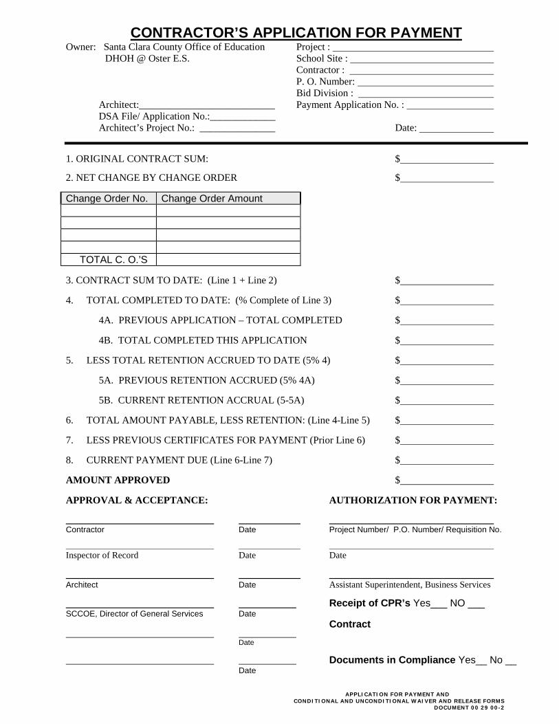
CONTRACTOR’S APPLICATION FOR PAYMENT
Owner: Santa Clara County Office of Education Project : DHOH @ Oster E.S. School Site : Contractor : P. O. Number: Bid Division : Architect:___________________________ Payment Application No. :
DSA File/ Application No.:_____________ Architect’s Project No.: _______________ Date:
1. ORIGINAL CONTRACT SUM: $
2. NET CHANGE BY CHANGE ORDER $
Change Order No. Change Order Amount TOTAL C. O.’S
3. CONTRACT SUM TO DATE: (Line 1 + Line 2) $
4. TOTAL COMPLETED TO DATE: (% Complete of Line 3) $
4A. PREVIOUS APPLICATION – TOTAL COMPLETED $
4B. TOTAL COMPLETED THIS APPLICATION $
5. LESS TOTAL RETENTION ACCRUED TO DATE (5% 4) $
5A. PREVIOUS RETENTION ACCRUED (5% 4A) $
5B. CURRENT RETENTION ACCRUAL (5-5A) $
6. TOTAL AMOUNT PAYABLE, LESS RETENTION: (Line 4-Line 5) $
7. LESS PREVIOUS CERTIFICATES FOR PAYMENT (Prior Line 6) $
8. CURRENT PAYMENT DUE (Line 6-Line 7) $
AMOUNT APPROVED $
APPROVAL & ACCEPTANCE: AUTHORIZATION FOR PAYMENT:
Contractor Date Project Number/ P.O. Number/ Requisition No. Inspector of Record Date Date
Architect Date Assistant Superintendent, Business Services
Receipt of CPR’s Yes___ NO ___ SCCOE, Director of General Services Date Contract Date
Documents in Compliance Yes__ No __ Date
APPLICATION FOR PAYMENT AND
CONDITIONAL AND UNCONDITIONAL WAIVER AND RELEASE FORMS DOCUMENT 00 29 00-2
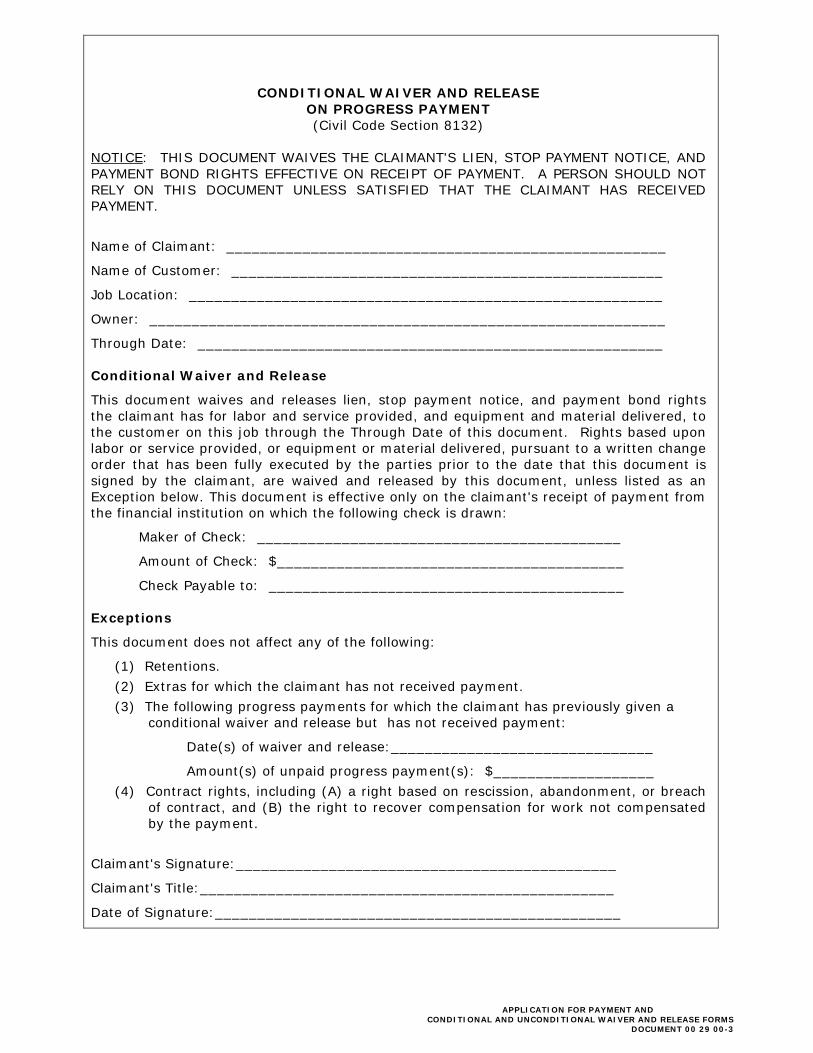
CONDITIONAL WAIVER AND RELEASE ON PROGRESS PAYMENT (Civil Code Section 8132)
NOTICE: THIS DOCUMENT WAIVES THE CLAIMANT'S LIEN, STOP PAYMENT NOTICE, AND PAYMENT BOND RIGHTS EFFECTIVE ON RECEIPT OF PAYMENT. A PERSON SHOULD NOT RELY ON THIS DOCUMENT UNLESS SATISFIED THAT THE CLAIMANT HAS RECEIVED PAYMENT.
Name of Claimant: ____________________________________________________
Name of Customer: ___________________________________________________
Job Location: ________________________________________________________
Owner: _____________________________________________________________
Through Date: _______________________________________________________ Conditional Waiver and Release
This document waives and releases lien, stop payment notice, and payment bond rights the claimant has for labor and service provided, and equipment and material delivered, to the customer on this job through the Through Date of this document. Rights based upon labor or service provided, or equipment or material delivered, pursuant to a written change order that has been fully executed by the parties prior to the date that this document is signed by the claimant, are waived and released by this document, unless listed as an Exception below. This document is effective only on the claimant's receipt of payment from the financial institution on which the following check is drawn:
Maker of Check: ___________________________________________
Amount of Check: $_________________________________________
Check Payable to: __________________________________________ Exceptions
This document does not affect any of the following:
(1) Retentions. (2) Extras for which the claimant has not received payment. (3) The following progress payments for which the claimant has previously given a
conditional waiver and release but has not received payment:
Date(s) of waiver and release:_______________________________
Amount(s) of unpaid progress payment(s): $___________________ (4) Contract rights, including (A) a right based on rescission, abandonment, or breach
of contract, and (B) the right to recover compensation for work not compensated by the payment.
Claimant's Signature:_____________________________________________
Claimant's Title:_________________________________________________
Date of Signature:________________________________________________
APPLICATION FOR PAYMENT AND
CONDITIONAL AND UNCONDITIONAL WAIVER AND RELEASE FORMS DOCUMENT 00 29 00-3
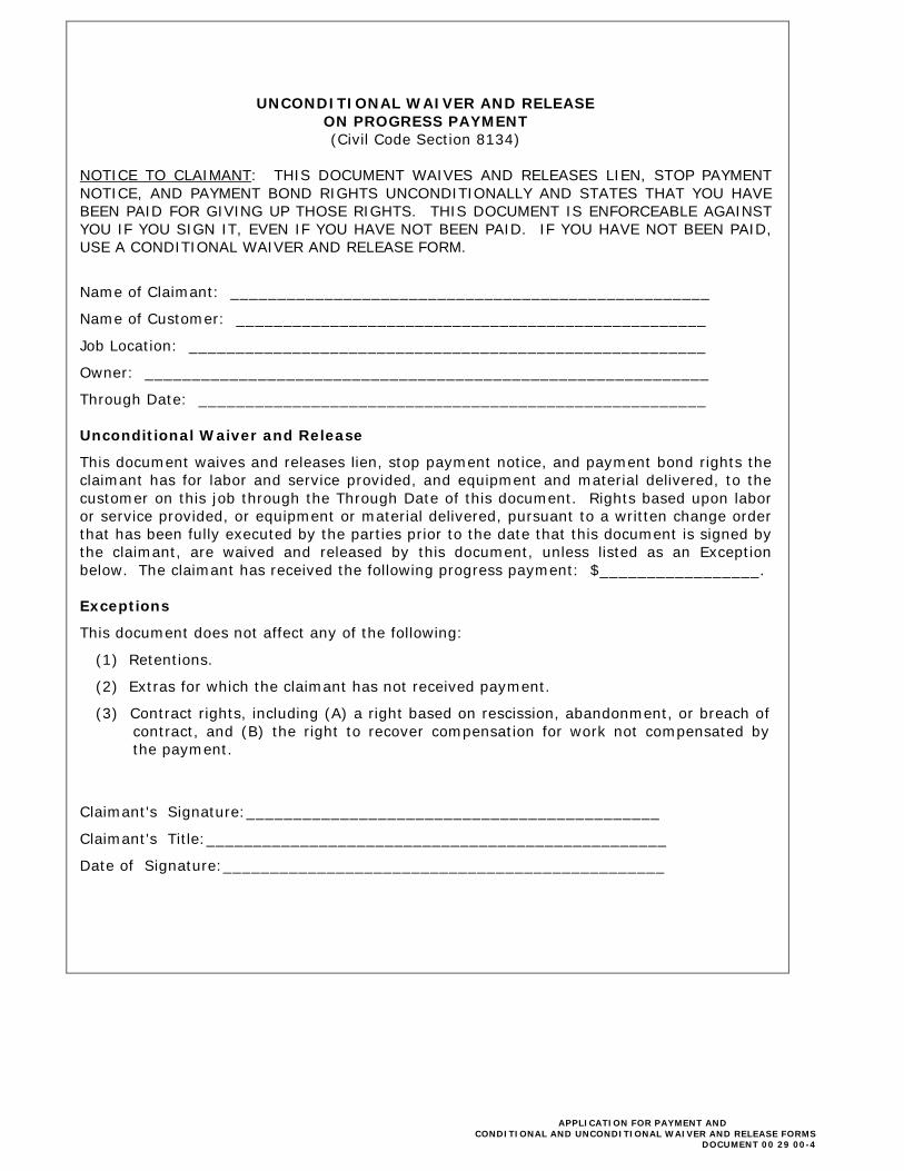
UNCONDITIONAL WAIVER AND RELEASE ON PROGRESS PAYMENT (Civil Code Section 8134)
NOTICE TO CLAIMANT: THIS DOCUMENT WAIVES AND RELEASES LIEN, STOP PAYMENT NOTICE, AND PAYMENT BOND RIGHTS UNCONDITIONALLY AND STATES THAT YOU HAVE BEEN PAID FOR GIVING UP THOSE RIGHTS. THIS DOCUMENT IS ENFORCEABLE AGAINST YOU IF YOU SIGN IT, EVEN IF YOU HAVE NOT BEEN PAID. IF YOU HAVE NOT BEEN PAID, USE A CONDITIONAL WAIVER AND RELEASE FORM.
Name of Claimant: ___________________________________________________
Name of Customer: __________________________________________________
Job Location: _______________________________________________________
Owner: ____________________________________________________________
Through Date: ______________________________________________________ Unconditional Waiver and Release
This document waives and releases lien, stop payment notice, and payment bond rights the claimant has for labor and service provided, and equipment and material delivered, to the customer on this job through the Through Date of this document. Rights based upon labor or service provided, or equipment or material delivered, pursuant to a written change order that has been fully executed by the parties prior to the date that this document is signed by the claimant, are waived and released by this document, unless listed as an Exception below. The claimant has received the following progress payment: $_________________. Exceptions
This document does not affect any of the following:
(1) Retentions.
(2) Extras for which the claimant has not received payment.
(3) Contract rights, including (A) a right based on rescission, abandonment, or breach of contract, and (B) the right to recover compensation for work not compensated by the payment.
Claimant's Signature:____________________________________________
Claimant's Title:_________________________________________________
Date of Signature:_______________________________________________
APPLICATION FOR PAYMENT AND
CONDITIONAL AND UNCONDITIONAL WAIVER AND RELEASE FORMS DOCUMENT 00 29 00-4

CONDITIONAL WAIVER AND RELEASE ON FINAL PAYMENT
(Civil Code Section 8136) NOTICE: THIS DOCUMENT WAIVES THE CLAIMANT'S LIEN, STOP PAYMENT NOTICE, AND PAYMENT BOND RIGHTS EFFECTIVE ON RECEIPT OF PAYMENT. A PERSON SHOULD NOT RELY ON THIS DOCUMENT UNLESS SATISFIED THAT THE CLAIMANT HAS RECEIVED PAYMENT.
Name of Claimant: ____________________________________________________
Name of Customer: ____________________________________________________
Job Location: _________________________________________________________
Owner: _____________________________________________________________ Conditional Waiver and Release
This document waives and releases lien, stop payment notice, and payment bond rights the claimant has for labor and service provided, and equipment and material delivered, to the customer on this job. Rights based upon labor or service provided, or equipment or material delivered, pursuant to a written change order that has been fully executed by the parties prior to the date that this document is signed by the claimant, are waived and released by this document, unless listed as an Exception below. This document is effective only on the claimant's receipt of payment from the financial institution on which the following check is drawn:
Maker of Check: ___________________________________________
Amount of Check: $_________________________________________
Check Payable to: __________________________________________ Exceptions
This document does not affect any of the following: __________________________
Disputed claims for extras in the amount of: $_______________________________
Claimant's Signature: _____________________________________________
Claimant's Title: _________________________________________________
Date of Signature: _______________________________________________
APPLICATION FOR PAYMENT AND
CONDITIONAL AND UNCONDITIONAL WAIVER AND RELEASE FORMS DOCUMENT 00 29 00-5
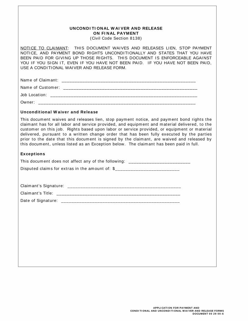
UNCONDITIONAL WAIVER AND RELEASE ON FINAL PAYMENT
(Civil Code Section 8138) NOTICE TO CLAIMANT: THIS DOCUMENT WAIVES AND RELEASES LIEN, STOP PAYMENT NOTICE, AND PAYMENT BOND RIGHTS UNCONDITIONALLY AND STATES THAT YOU HAVE BEEN PAID FOR GIVING UP THOSE RIGHTS. THIS DOCUMENT IS ENFORCEABLE AGAINST YOU IF YOU SIGN IT, EVEN IF YOU HAVE NOT BEEN PAID. IF YOU HAVE NOT BEEN PAID, USE A CONDITIONAL WAIVER AND RELEASE FORM.
Name of Claimant: ____________________________________________________
Name of Customer: ____________________________________________________
Job Location: _________________________________________________________
Owner: _____________________________________________________________ Unconditional Waiver and Release
This document waives and releases lien, stop payment notice, and payment bond rights the claimant has for all labor and service provided, and equipment and material delivered, to the customer on this job. Rights based upon labor or service provided, or equipment or material delivered, pursuant to a written change order that has been fully executed by the parties prior to the date that this document is signed by the claimant, are waived and released by this document, unless listed as an Exception below. The claimant has been paid in full. Exceptions
This document does not affect any of the following: ________________________
Disputed claims for extras in the amount of: $_________________________
Claimant's Signature: ____________________________________________
Claimant's Title: ________________________________________________
Date of Signature: ______________________________________________
APPLICATION FOR PAYMENT AND
CONDITIONAL AND UNCONDITIONAL WAIVER AND RELEASE FORMS DOCUMENT 00 29 00-6
DOCUMENT 01 31 19
PROJECT MEETINGS PART I – GENERAL 1.01 RELATED DOCUMENTS AND PROVISIONS:
All Contract Documents should be reviewed for applicable provisions related to the provisions in this document, including without limitation:
A. General Conditions; B. Special Conditions;
C. Summary of Work; and
D. Submittals.
1.02 SECTION INCLUDES:
A. Scheduling of Work under this Contract shall be performed by Contractor in accordance with requirements of this Section.
(1) Submit schedules and reports as specified in the General Conditions.
B. Upon Award of Contract, Contractor shall immediately commence development
of Initial and Original Schedules to ensure compliance with Schedule submittal requirements.
1.03 CONSTRUCTION SCHEDULE:
A. Within ten (10) days of being awarded the Contract and before request for first progress payment, the Contractor shall prepare and submit to the Project Manager a construction progress schedule conforming to the Milestone Schedule below.
B. The Construction Schedule shall be continuously updated, and an updated
schedule shall be submitted with each application for progress payment. Each revised schedule shall indicate the work actually accomplished during the previous period and the schedule for completion of the remaining work.
PROJECT MEETINGS DOCUMENT 01 31 19-1
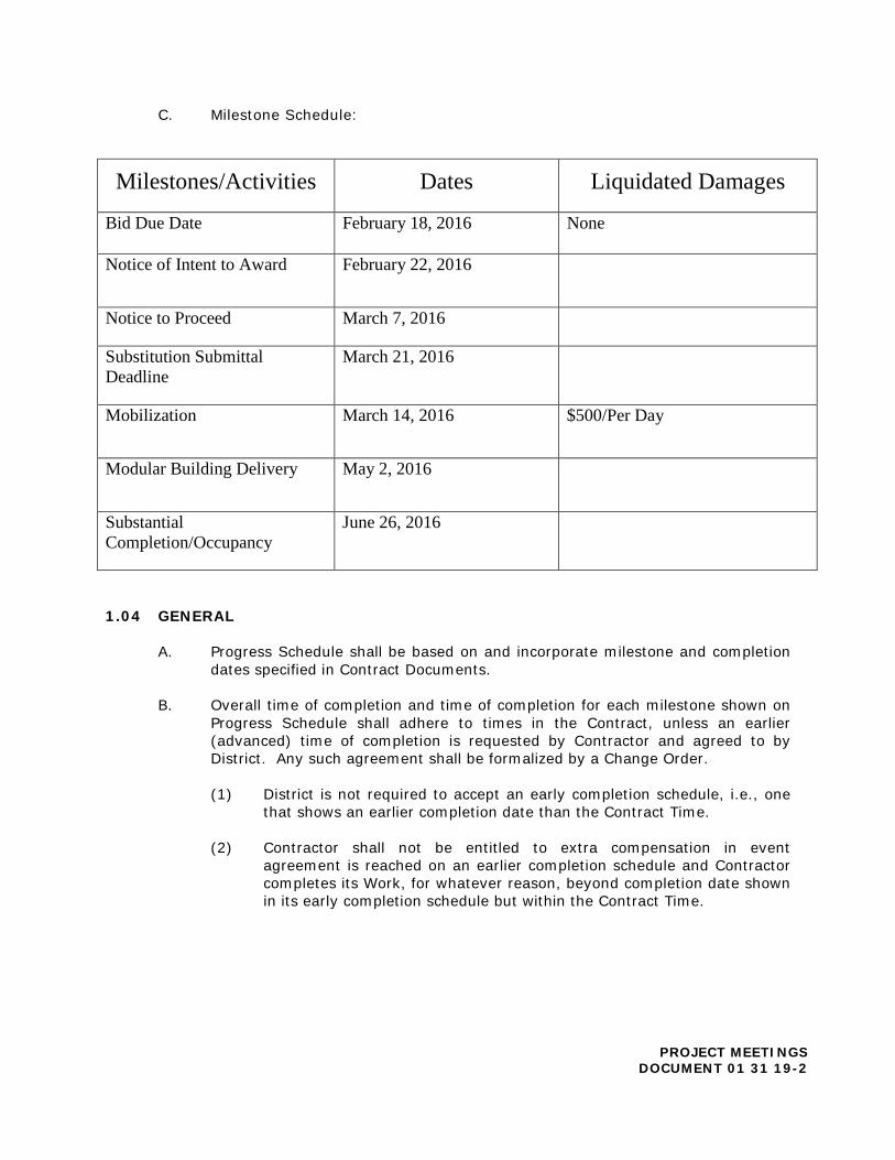
C. Milestone Schedule:
Milestones/Activities Dates Liquidated Damages
Bid Due Date February 18, 2016 None
Notice of Intent to Award February 22, 2016
Notice to Proceed March 7, 2016
Substitution Submittal Deadline
March 21, 2016
Mobilization March 14, 2016 $500/Per Day
Modular Building Delivery May 2, 2016
Substantial Completion/Occupancy
June 26, 2016
1.04 GENERAL
A. Progress Schedule shall be based on and incorporate milestone and completion dates specified in Contract Documents.
B. Overall time of completion and time of completion for each milestone shown on
Progress Schedule shall adhere to times in the Contract, unless an earlier (advanced) time of completion is requested by Contractor and agreed to by District. Any such agreement shall be formalized by a Change Order.
(1) District is not required to accept an early completion schedule, i.e., one
that shows an earlier completion date than the Contract Time. (2) Contractor shall not be entitled to extra compensation in event
agreement is reached on an earlier completion schedule and Contractor completes its Work, for whatever reason, beyond completion date shown in its early completion schedule but within the Contract Time.
PROJECT MEETINGS DOCUMENT 01 31 19-2

(3) A schedule showing the work completed in less than the Contract Time, and that has been accepted by District, shall be considered to have Project Float. The Project Float is the time between the scheduled completion of the work and the Completion Date. Project Float is a resource available to both District and the Contractor.
C. Ownership Project Float: Neither the District nor Contractor owns Project Float.
The Project owns the Project Float. As such, liability for delay of the Completion Date rests with the party whose actions, last in time, actually cause delay to the Completion Date. (1) For example, if Party A uses some, but not all of the Project Float and
Party B later uses remainder of the Project Float as well as additional time beyond the Project Float, Party B shall be liable for the time that represents a delay to the Completion Date.
(2) Party A would not be responsible for the time since it did not consume
the entire Project Float and additional Project Float remained; therefore, the Completion Date was unaffected by Party A.
D. Rain Days: Project schedules shall incorporate the following average monthly
rain days.
January [11] July [0] February [10] August [0] March [10] September [1] April [6] October [4] May [3] November [7] June [1] December [10]
E. Progress Schedule shall be the basis for evaluating job progress, payment
requests, and time extension requests. Responsibility for developing Contract Schedule and monitoring actual progress as compared to Progress Schedule rests with Contractor.
F. Failure of Progress Schedule to include any element of the Work, or any
inaccuracy in Progress Schedule, will not relieve Contractor from responsibility for accomplishing the Work in accordance with the Contract. District’s acceptance of schedule shall be for its use in monitoring and evaluating job progress, payment requests, and time extension requests and shall not, in any manner, impose a duty of care upon District, or act to relieve Contractor of its responsibility for means and methods of construction.
G. Software: Use software approved by District. Such software shall be compatible
with Windows operating system. Contractor shall transmit contract file to District on compact disk at times requested by District.
PROJECT MEETINGS DOCUMENT 01 31 19-3

H. Transmit each item under the form approved by District.
(1) Identify Project with District Contract number and name of Contractor. (2) Provide space for Contractor’s approval stamp and District’s review
stamps. (3) Submittals received from sources other than Contractor will be returned
to the Contractor without District’s review.
1.05 INITIAL SCHEDULE
A Initial Schedule submitted for review at the pre-construction conference shall serve as Contractor’s schedule for up to thirty (30) calendar days after the Notice to Proceed.
B. Indicate detailed plan for the Work to be completed in first thirty (30) days of
the Contract; details of planned mobilization of plant and equipment; sequence of early operations; procurement of materials and equipment. Show Work beyond thirty (30) calendar days in summary form.
C. Initial Schedule shall be time-scaled. D. District and Contractor shall meet to review and discuss the Initial Schedule
within seven (7) calendar days after it has been submitted to District.
(1) District’s review and comment on the schedule shall be limited to Contract conformance (with sequencing, coordination, and milestone requirements).
(2) Contractor shall make corrections to schedule necessary to comply with
Contract requirements and shall adjust schedule to incorporate any missing information requested by District. Contractor shall resubmit Initial Schedule if requested by District.
E. If, during the first thirty (30) days after Notice to Proceed, the Contractor is of
the opinion that any of the Work included on its Initial Schedule has been impacted, the Contractor shall submit to District a written Time Impact Evaluation (“TIE”) in accordance with Article 1.12 of this Section. The TIE shall be based on the most current update of the Initial Schedule.
1.07 ORIGINAL SCHEDULE
A. Submit a detailed proposed Original Schedule presenting an orderly and realistic plan for completion of the Work in conformance with requirements as specified herein.
B. Progress Schedule shall include or comply with following requirements:
(1) Time scaled schedule.
PROJECT MEETINGS DOCUMENT 01 31 19-4

(2) No activity on schedule shall have duration longer than fifteen (15) work days, with exception of submittal, approval, fabrication and procurement activities, unless otherwise approved by District.
(a) Activity durations shall be total number of actual work days required to perform that activity.
(3) The start and completion dates of all items of Work, their major components, and milestone completion dates, if any.
(4) District -furnished materials and equipment, if any, identified as separate
activities. (5) Activities for maintaining Project Record Documents. (6) Dependencies (or relationships) between activities. (7) Processing/approval of submittals and shop drawings for all material and
equipment required per the Contract. Activities that are dependent on submittal acceptance or material delivery shall not be scheduled to start earlier than expected acceptance or delivery dates.
(a) Include time for submittals, re-submittals and reviews by District. Coordinate with accepted schedule for submission of Shop Drawings, samples, and other submittals.
(b) Contractor shall be responsible for all impacts resulting from re-submittal of Shop Drawings and submittals.
(8) Procurement of major equipment, through receipt and inspection at
jobsite, identified as separate activity.
(a) Include time for fabrication and delivery of manufactured products for the Work.
(b) Show dependencies between procurement and construction.
(9) Activity description; what Work is to be accomplished and where. (10) Responsibility code for each activity corresponding to Contractor or
Subcontractor responsible for performing the Work. (11) Identify the activities which constitute the controlling operations or
critical path. No more than twenty-five (25%) of the activities shall be critical or near critical. Near critical is defined as float in the range of one (1) to (10) days.
(12) Five (5) workdays for developing punch list(s), completion of punch-list
items, and final clean up for the Work or any designated portion thereof. No other activities shall be scheduled during this period.
PROJECT MEETINGS DOCUMENT 01 31 19-5
(13) Interface with the work of other contractors, District, and agencies such as, but not limited to, utility companies.
(14) Show detailed Subcontractor Work activities. In addition, furnish copies
of Subcontractor schedules upon which schedule was built.
(a) Also furnish for each Subcontractor, as determined by District, submitted on Subcontractor letterhead, a statement certifying that Subcontractor concurs with Contractor’s Original Schedule and that Subcontractor’s related schedules have been incorporated.
(b) Subcontractor schedules shall be independently derived and not a copy of Contractor’s schedule.
(c) Furnish schedule for Contractor/Subcontractor schedule meetings which shall be held prior to submission of Original schedule to District. District shall be permitted to attend scheduled meetings as an observer.
(17) Activity durations shall be in Work days. (18) Submit with the schedule a list of anticipated non-Work days, such as
weekends and holidays. The Progress Schedule shall exclude in its Work day calendar all non-Work days on which Contractor anticipates critical Work will not be performed.
C. Original Schedule Review Meeting: Contractor shall, within ten (10) days from
the Notice to Proceed date, meet with District to review the Original Schedule submittal.
(1) Contractor shall have its Project Manager, Project Superintendent, and
key Subcontractor representatives, as required by District, in attendance. The meeting will take place over a continuous one (1) day period.
(2) District’s review will be limited to submittal’s conformance to Contract
requirements including, but not limited to, coordination requirements. However, review may also include:
(a) Clarifications of Contract Requirements. (b) Directions to include activities and information missing from submittal. (c) Requests to Contractor to clarify its schedule.
(3) Within five (5) days of the Schedule Review Meeting, Contractor shall
respond in writing to all questions and comments expressed by District at the Meeting.
PROJECT MEETINGS DOCUMENT 01 31 19-6
1.08 ADJUSTMENTS TO SCHEDULE
A. Adjustments to Original Schedule: Contractor shall have adjusted the Original
Schedule submittal to address all review comments from original Schedule review meeting and resubmit for District’s review. (1) District, within ten (10) days from date that Contractor submitted the
revised schedule, will either:
(a) Accept schedule as submitted, or
(b) Advise Contractor in writing to review any part or parts of schedule which either do not meet Contract requirements or are unsatisfactory for District to monitor Project’s progress, resources, and status or evaluate monthly payment request by Contractor.
(2) District may accept schedule with conditions that the first monthly Schedule update be revised to correct deficiencies identified.
(3) When schedule is accepted, it shall be considered the “Original Schedule”
which will then be immediately updated to reflect the current status of the work.
(4) District reserves right to require Contractor to adjust, add to, or clarify
any portion of schedule which may later be discovered to be insufficient for monitoring of Work or approval of partial payment requests. No additional compensation will be provided for such adjustments, additions, or clarifications.
(5) Delays in the work, as determined to be on the critical path due to rain,
may be granted time extensions provided they exceed the average annual rainfall, but those additional days are non-compensatory to the Contractor.
B. Acceptance of Contractor’s schedule by District will be based solely upon
schedule’s compliance with Contract requirements.
(1) By way of Contractor assigning activity durations and proposing sequence of Work, Contractor agrees to utilize sufficient and necessary management and other resources to perform work in accordance with the schedule.
(2) Upon submittal of schedule update, updated schedule shall be
considered “current” Schedule. (3) Submission of Contractor’s schedule to District shall not relieve
Contractor of total responsibility for scheduling, sequencing, and pursuing Work to comply with requirements of Contract Documents, including adverse effects such as delays resulting from ill-timed Work.
PROJECT MEETINGS DOCUMENT 01 31 19-7
C. Submittal of Original Schedule, and subsequent schedule updates, shall be understood to be Contractor’s representation that the Schedule meets requirements of Contract Documents and that Work shall be executed in sequence indicated on the schedule.
D. Contractor shall distribute Original Schedule to Subcontractors for review and
written acceptance, which shall be noted on Subcontractors’ letterheads to Contractor and transmitted to District for the record.
1.09 MONTHLY SCHEDULE UPDATE SUBMITTALS
A. Following acceptance of Contractor’s Original Schedule, Contractor shall monitor progress of Work and adjust schedule each month to reflect actual progress and any anticipated changes to planned activities.
(1) Each schedule update submitted shall be complete, including all
information requested for the Original Schedule submittal. (2) Each update shall continue to show all Work activities including those
already completed. These completed activities shall accurately reflect “as built” information by indicating when activities were actually started and completed.
B. A meeting will be held on approximately the twenty-fifth (25th) of each month to
review the schedule update submittal and progress payment application.
(1) At this meeting, at a minimum, the following items will be reviewed: Percent (%) complete of each activity; Time Impact Evaluations for Change Orders and Time Extension Request; actual and anticipated activity sequence changes; actual and anticipated duration changes; and actual and anticipated Contractor delays.
(2) These meetings are considered a critical component of overall monthly
schedule update submittal and Contractor shall have appropriate personnel attend. At a minimum, these meetings shall be attended by Contractor’s General Superintendent and Project Manager.
(3) Contractor shall plan on the meeting taking no less than one (1) hour.
C. Within five (5) working days after monthly schedule update meeting, Contractor
shall submit the updated Schedule. D. Within five (5) work days of receipt of above noted revised submittals, District
will either accept or reject monthly schedule update submittal.
PROJECT MEETINGS DOCUMENT 01 31 19-8
(1) If accepted, percent (%) complete shown in monthly update will be basis for Application for Payment by the Contractor. The schedule update shall be submitted as part of the Contractor’s Application for Payment.
(2) If rejected, update shall be corrected and resubmitted by Contractor before the Application for Payment is submitted.
E. Neither updating, changing or revising of any report, curve, schedule, or
narrative submitted to District by Contractor under this Contract, nor District’s review or acceptance of any such report, curve, schedule or narrative shall have the effect of amending or modifying in any way the Completion Date or milestone dates or of modifying or limiting in any way Contractor’s obligations under this Contract.
1.10 SCHEDULE REVISIONS
A. Updating the Schedule to reflect actual progress shall not be considered revisions to the Schedule. Since scheduling is a dynamic process, revisions to activity durations and sequences are expected on a monthly basis.
B. To reflect revisions to the schedule, the Contractor shall provide District with a
written narrative with a full description and reasons for each Work activity revised. For revisions affecting the sequence of work, the Contractor shall provide a schedule diagram which compares the original sequence to the revised sequence of work. The Contractor shall provide the written narrative and schedule diagram for revisions two (2) working days in advance of the monthly schedule update meeting.
C. Schedule revisions shall not be incorporated into any schedule update until the
revisions have been reviewed by District. District may request further information and justification for schedule revisions and Contractor shall, within three (3) days, provide District with a complete written narrative response to District’s request.
D. If the Contractor’s revision is still not accepted by District, and the Contractor
disagrees with District’s position, the Contractor has seven (7) calendar days from receipt of District’s letter rejecting the revision to provide a written narrative providing full justification and explanation for the revision. The Contractor’s failure to respond in writing within seven (7) calendar days of District’s written rejection of a schedule revision shall be contractually interpreted as acceptance of District’s position, and the Contractor waives its rights to subsequently dispute or file a claim regarding District’s position.
E. At District’s discretion, the Contractor can be required to provide Subcontractor
certifications of performance regarding proposed schedule revisions affecting said Subcontractors.
1.11 RECOVERY SCHEDULE
PROJECT MEETINGS DOCUMENT 01 31 19-9

A. If the Schedule Update shows a completion date fourteen (14) calendar days beyond the Contract Completion Date, or individual milestone completion dates, the Contractor shall submit to District the proposed revisions to recover the lost time within seven (7) calendar days. As part of this submittal, the Contractor shall provide a written narrative for each revision made to recapture the lost time. If the revisions include sequence changes, the Contractor shall provide a schedule diagram comparing the original sequence to the revised sequence of work.
B. The revisions shall not be incorporated into any schedule update until the
revisions have been reviewed by District. C. If the Contractor’s revisions are not accepted by District, District and the Contractor
shall follow the procedures in paragraph 1.09.C, 1.09.D and 1.09.E above. D. At District’s discretion, the Contractor can be required to provide Subcontractor
certifications for revisions affecting said Subcontractors. 1.12 TIME IMPACTS EVALUATION (“TIE”) FOR CHANGE ORDERS, AND OTHER
DELAYS
A. When Contractor is directed to proceed with changed Work, the Contractor shall prepare and submit within fourteen (14) calendar days from the Notice to Proceed a TIE which includes both a written narrative and a schedule diagram depicting how the changed Work affects other schedule activities. The schedule diagram shall show how the Contractor proposes to incorporate the changed Work in the schedule and how it impacts the current schedule-update critical path. The Contractor is also responsible for requesting time extensions based on the TIE’s impact on the critical path. The diagram must be tied to the main sequence of schedule activities to enable District to evaluate the impact of changed Work to the scheduled critical path.
B. Contractor shall be required to comply with the requirements of Paragraph 1.09.A for
all types of delays such as, but not limited to, Contractor/Subcontractor delays, adverse weather delays, strikes, procurement delays, fabrication delays, etc.
C. Contractor shall be responsible for all costs associated with the preparation of
TIEs, and the process of incorporating them into the current schedule update. The Contractor shall provide District with four (4) copies of each TIE.
D. Once agreement has been reached on a TIE, the Contract Time will be adjusted
accordingly. If agreement is not reached on a TIE, the Contract Time may be extended in an amount District allows, and the Contractor may submit a claim for additional time claimed by contractor.
PROJECT MEETINGS DOCUMENT 01 31 19-10
1.13 TIME EXTENSIONS
A. The Contractor is responsible for requesting time extensions for time impacts that, in the opinion of the Contractor, impact the critical path of the current schedule update. Notice of time impacts shall be given in accord with the General Conditions.
B. Where an event for which District is responsible impacts the projected
Completion Date, the Contractor shall provide a written mitigation plan, including a schedule diagram, which explains how (e.g., increase crew size, overtime, etc.) the impact can be mitigated. The Contractor shall also include a detailed cost breakdown of the labor, equipment, and material the Contractor would expend to mitigate District-caused time impact. The Contractor shall submit its mitigation plan to District within fourteen (14) calendar days from the date of discovery of the impact. The Contractor is responsible for the cost to prepare the mitigation plan.
C. Failure to request time, provide TIE, or provide the required mitigation plan will
result in Contractor waiving its right to a time extension and cost to mitigate the delay.
D. No time will be granted under this Contract for cumulative effect of changes.
E. District will not be obligated to consider any time extension request unless the
Contractor complies with the requirements of Contract Documents. F. Failure of the Contractor to perform in accordance with the current schedule
update shall not be excused by submittal of time extension requests. G. If the Contractor does not submit a TIE within the required fourteen (14)
calendar days for any issue, it is mutually agreed that the Contractor does not require a time extension for said issue.
1.14 SCHEDULE REPORTS
A. Submit four (4) copies of the following reports with the Initial Schedule, the Original Schedule, and each monthly update.
B. Required Reports:
(1) Two activity listing reports: one sorted by activity number and one by
total Project Float. These reports shall also include each activity’s early/late and actual start and finish dates, original and remaining duration, Project Float, responsibility code, and the logic relationship of activities.
(2) Schedule plots presenting time-scaled network diagram showing
activities and their relationships with the controlling operations or critical path clearly highlighted.
PROJECT MEETINGS DOCUMENT 01 31 19-11

(3) Planned versus actual resource (i.e., labor) histogram calculated by early start and late start.
C. Other Reports
In addition to above reports, District may request, from month-to-month, any two of the following reports. Submit four (4) copies of all reports.
(1) Activities by early start. (2) Activities by late start. (3) Activities grouped by Subcontractors or selected trades. (4) Activities with scheduled early start dates in a given time frame, such as
fifteen (15) or thirty (30) day outlook.
D. Furnish District with electronic files containing all schedule files for each report generated.
1.15 PROJECT STATUS REPORTING
A. In addition to submittal requirements for scheduling identified in this Section, Contractor shall provide a monthly project status report (i.e., written narrative report) to be submitted in conjunction with each Schedule as specified herein. Status reporting shall be in form specified below.
B. Contractor shall prepare monthly written narrative reports of status of Project
for submission to District. Written status reports shall include:
(1) Status of major Project components (percent (%) complete, amount of time ahead or behind schedule) and an explanation of how Project will be brought back on schedule if delays have occurred.
(2) Progress made on critical activities indicated on CPM Schedule. (3) Explanations for any lack of work on critical path activities planned to be
performed during last month. (4) Explanations for any schedule changes, including changes to logic or to
activity durations. (5) List of critical activities scheduled to be performed next month. (6) Status of major material and equipment procurement. (7) Any delays encountered during reporting period. (8) Contractor shall provide printed report indicating actual versus planned
resource loading for each trade and each activity. This report shall be provided on weekly and monthly basis.
PROJECT MEETINGS DOCUMENT 01 31 19-12
(a) Actual resource shall be accumulated in field by Contractor, and shall
be as noted on Contractor’s daily reports. These reports will be basis for information provided in computer-generated monthly and weekly printed reports.
(b) Contractor shall explain all variances and mitigation measures.
(9) Contractor may include any other information pertinent to status of
Project. Contractor shall include additional status information requested by District at no additional cost.
(10) Status reports, and the information contained therein, shall not be
construed as claims, notice of claims, notice of delay, or requests for changes or compensation.
1.16 WEEKLY SCHEDULE REPORT
At the Weekly Progress Meeting, the Contractor shall provide and present a time-scaled three (3) week look-ahead schedule that is based and correlated by activity number to the current schedule (i.e., Initial, Original, or Schedule Update).
1.17 DAILY CONSTRUCTION REPORTS
On a daily basis, Contractor shall submit a daily activity report to District for each workday, including weekends and holidays when worked. Contractor shall develop the daily construction reports on a computer-generated database capable of sorting daily Work, manpower, and manhours by Contractor, Subcontractor, area, sub-area, and Change Order Work. Upon request of District, furnish computer disk of this data base. Obtain District’s written approval of daily construction report data base format prior to implementation. Include in report:
A. Project name and Project number. B. Contractor’s name and address. C. Weather, temperature, and any unusual site conditions. D. Brief description and location of the day’s scheduled activities and any special
problems and accidents, including Work of Subcontractors. Descriptions shall be referenced to CPM scheduled activities.
E. Worker quantities for its own Work force and for Subcontractors of any tier. F. Equipment, other than hand tools, utilized by Contractor and Subcontractors.
1.18 PERIODIC VERIFIED REPORTS
Contractor shall complete and verify construction reports on a form prescribed by the Division of the State Architect and file reports on the first day of February, May, August, and November during the preceding quarter year; at the completion of the Contract; at
PROJECT MEETINGS DOCUMENT 01 31 19-13
the completion of the Work; at the suspension of Work for a period of more than one (1) month; whenever the services of Contractor or any of Contractor’s Subcontractors are terminated for any reason; and at any time a special verified report is required by the Division of the State Architect. Refer to section 4-336 and section 4-343 of Part 1, Title 24 of the California Code of Regulations.
PART 2 - PRODUCTS Not Used. PART 3 - EXECUTION Not Used.
END OF DOCUMENT
PROJECT MEETINGS DOCUMENT 01 31 19-14
DOCUMENT 01 33 00
SUBMITTALS PART 1 - GENERAL 1.01 RELATED DOCUMENTS AND PROVISIONS:
All Contract Documents should be reviewed for applicable provisions related to the provisions in this document, including without limitation:
A. General Conditions, including, without limitation, Contractor’s Submittals and
Schedules, Drawings and Specifications; B. Special Conditions.
1.02 SECTION INCLUDES:
A. Definitions:
(1) Shop Drawings and Product Data are as indicated in the General Conditions and include, but are not limited to, fabrication, erection, layout and setting drawings, formwork and falsework drawings, manufacturers' standard drawings, descriptive literature, catalogues, brochures, performance and test data, wiring and control diagrams. In addition, there are other drawings and descriptive data pertaining to materials, equipment, piping, duct and conduit systems, and methods of construction as may be required to show that the materials, equipment or systems and all positions conform to the requirement of the Contract Documents, including, without limitation, the Drawings.
(2) "Manufactured" applies to standard units usually mass-produced;
"fabricated" means specifically assembled or made out of selected materials to meet design requirements. Shop Drawings shall establish the actual detail of manufactured or fabricated items, indicated proper relation to adjoining work and amplify design details of mechanical and electrical equipment in proper relation to physical spaces in the structure.
(3) Manufacturer's Instructions: Where any item of Work is required by the
Contract Documents to be furnished, installed, or performed, at a minimum, in accordance with a specified product manufacturer's instructions, the Contractor shall procure and distribute copies of these to the District, the Architect, and all other concerned parties and shall furnish, install, or perform the work, at a minimum, in accordance with those instructions.
B. Samples, Shop Drawings, Product Data, and other items as specified, in
accordance with the following requirements:
SUBMITTALS DOCUMENT 01 33 00-1
(1) Contractor shall submit all Shop Drawings, Product Data, and Samples to the District, the Architect, the Project Inspector, and the Construction Manager.
(2) Contractor shall comply with all time frames herein and in the General
Conditions and, in any case, shall submit required information in sufficient time to permit proper consideration and action before ordering any materials or items represented by such Shop Drawings, Product Data, and/or Samples.
(3) Contractor shall comply with all time frames herein and in the General
Conditions and, in any case, shall allow sufficient time so that no delay occurs due to required lead time in ordering or delivery of any item to the Site. Contractor shall be responsible for any delay in progress of Work due to its failure to observe these requirements.
(4) Time for completion of Work shall not be extended on account of
Contractor's failure to promptly submit Shop Drawings, Product Data, and/or Samples.
(5) Reference numbers on Shop Drawings shall have Architectural and/or
Engineering Contract Drawings reference numbers for details, sections, and “cuts” shown on Shop Drawings. These reference numbers shall be in addition to any numbering system that Contractor chooses to use or has adopted as standard.
(6) When the magnitude or complexity of submittal material prevents a
complete review within the stated time frame, Contractor shall make this submittal in increments to avoid extended delays.
(7) Contractor shall certify on submittals for review that submittals conform
to Contract requirements. In event of any variance, Contractor shall specifically state in transmittal and on Shop Drawings, portions vary and require approval of a substitute. Also certify that Contractor-furnished equipment can be installed in allocated space.
(8) Unless specified otherwise, sampling, preparation of samples, and tests
shall be in accordance with the latest standard of the American Society for Testing and Materials.
(9) Upon demand by Architect or District, Contractor shall submit samples of
materials and/or articles for tests or examinations and consideration before Contractor incorporates same in Work. Contractor shall be solely responsible for delays due to sample(s) not being submitted in time to allow for tests. Acceptance or rejection will be expressed in writing. Work shall be equal to approved samples in every respect. Samples that are of value after testing will remain the property of Contractor.
C. Submittal Schedule:
(1) Contractor shall prepare its proposed submittal schedule that is
coordinated with its proposed construction schedule and submit both to SUBMITTALS DOCUMENT 01 33 00-2
the District within ten (10) days after the date of the Notice to Proceed. Contractor's proposed schedules shall become the Project Construction Schedule and the Project Submittal Schedule after each is approved by the District.
(2) Contractor is responsible for all lost time should the initial submittal be
rejected, marked "revised and resubmit", etc.
(3) All Submittals shall be forwarded to the District by the date indicated on the approved Submittal Schedule, unless an earlier date is necessary to maintain the Construction Schedule, in which case those Submittals shall be forwarded to the District so as not to delay the Construction Schedule..
1.03 SHOP DRAWINGS:
A. Contractor shall submit four (4) copies. The District will review and return one copy to Contractor.
B. Before commencing installation of any Work, the Contractor shall submit and
receive approval of all drawings, descriptive data, and material list(s) as required to accomplish Work.
C. Review of Shop Drawings is regarded as a service to assist Contractor and in all
cases original Contract Documents shall take precedence as outlined under General Conditions.
D. No claim for extra time or payment shall be based on work shown on Shop
Drawings unless the claim is (1) noted on Contractor's transmittal letter accompanying Shop Drawings and (2) Contractor has complied with all applicable provisions of the General Conditions, including, without limitation, provisions regarding changes and payment, and all required written approvals.
E. District shall not review Shop Drawings for quantities of materials or number of
items supplied.
F. District's and/or Architect’s review of Shop Drawing will be general. District and/or Architect review does not relieve Contractor of responsibility for accuracy, proper fitting, construction of Work, furnishing of materials, or Work required by Contract Documents and not indicated on Shop Drawings. Shop Drawing reviewed by District and/or Architect is not to be construed as approving departures from Contract Documents.
G. Review of Shop Drawings and Schedules does not relieve Contractor from
responsibility for any aspect of those Drawings or Schedules that is a violation of local, County, State, or Federal laws, rules, ordinances, or rules and regulations of commissions, boards, or other authorities or utilities having jurisdiction.
H. Before submitting Shop Drawings for review, Contractor shall check Shop
Drawings of its subcontractors for accuracy, and confirm that all Work contiguous with and having bearing on other work shown on Shop Drawings is accurately drawn and in conformance with Contract Documents.
SUBMITTALS DOCUMENT 01 33 00-3
I. Submitted drawings and details must bear stamp of approval of Contractor:
(1) Stamp and signature shall clearly certify that Contractor has checked
Shop Drawings for compliance with Drawings. (2) If Contractor submits a Shop Drawing without an executed stamp of
approval, or whenever it is evident (despite stamp) that Drawings have not been checked the District and/or Architect will not consider them and will return them to the Contractor for revision and resubmission. In that event, it will be deemed that Contractor has not complied with this provision and Contractor shall bear risk of all delays to same extent as if it had not submitted any Shop Drawings or details.
J. Submission of Shop Drawings (in either original submission or when resubmitted
with correction) constitutes evidence that Contractor has checked all information thereon and that it accepts and is willing to perform Work as shown.
K. Contractor shall pay for cost of any changes in construction due to improper
checking and coordination. Contractor shall be responsible for all additional costs, including coordination. Contractor shall be responsible for costs incurred by itself, the District, the Architect, the Project Inspector, the Construction Manager, any other Subcontractor or contractor, etc., due to improperly checked and/or coordination of submittals.
L. Shop Drawings must clearly delineate the following information:
(1) Project name and address. (2) Architect's name and project number.
(3) Shop Drawing title, number, date, and scale.
(4) Names of Contractor, Subcontractor(s) and fabricator.
(5) Working and erection dimensions.
(6) Arrangements and sectional views.
(7) Necessary details, including complete information for making connections
with other Work.
(8) Kinds of materials and finishes.
(9) Descriptive names of materials and equipment, classified item numbers, and locations at which materials or equipment are to be installed in the Work. Contractor shall use same reference identification(s) as shown on Contract Drawings.
M. Contractor shall prepare composite drawings and installation layouts when
required to solve tight field conditions. SUBMITTALS DOCUMENT 01 33 00-4
(1) Shop Drawings shall consist of dimensioned plans and elevations and must give complete information, particularly as to size and location of sleeves, inserts, attachments, openings, conduits, ducts, boxes, structural interferences, etc.
(2) Contractor shall coordinate these composite Shop Drawings and
installation layouts in the field between itself and its Subcontractor(s) for proper relationship to the Work, the work of other trades, and the field conditions. The Contractor shall check and approve all submittal(s) before submitting them for final review.
1.04 PRODUCT DATA OR NON REPRODUCIBLE SUBMITTALS:
A. Contractor shall submit manufacturer's printed literature in original form. Any fading type of reproduction will not be accepted. Contract must submit a minimum of six (6) each, to the District. District shall return one (1) to the Contractor, who shall reproduce whatever additional copies it requires for distribution.
B. Contractor shall submit six (6) copies of a complete list of all major items of
mechanical, plumbing, and electrical equipment and materials in accordance with the approved Submittal Schedule, except as required earlier to comply with the approved Construction Schedule. Other items specified are to be submitted prior to commencing Work. Contractor shall submit items of like kind at one time in a neat and orderly manner. Partial lists will not be acceptable.
C. Submittals shall include manufacturer's specifications, physical dimensions, and
ratings of all equipment. Contractor shall furnish performance curves for all pumps and fans. Where printed literature describes items in addition to that item being submitted, submitted item shall be clearly marked on sheet and superfluous information shall be crossed out. If highlighting is used, Contractor shall mark all copies.
D. Equipment submittals shall be complete and include space requirements,
weight, electrical and mechanical requirements, performance data, and supplemental information that may be requested.
1.05 SAMPLES:
A. Contractor shall submit for approval Samples as required and within the time frame in the Contract Documents. Materials such as concrete, mortar, etc., which require on-site testing will be obtained from Project Site.
B. Contractor shall submit four (4) samples except where greater or lesser number
is specifically required by Contract Documents including, without limitation, the Specifications.
(1) Samples must be of sufficient size and quality to clearly illustrate
functional characteristics, with integrally related parts and attachment devices.
(2) Samples must show full range of texture, color, and pattern.
SUBMITTALS DOCUMENT 01 33 00-5

C. Contractor shall make all Submittals, unless it has authorized Subcontractor(s)
to submit and Contractor has notified the District in writing to this effect. D. Samples to be shipped prepaid or hand-delivered to the District.
E. Contractor shall mark samples to show name of Project, name of Contractor
submitting, Contract number and segment of Work where representative Sample will be used, all applicable Specifications Sections and documents, Contract Drawing Number and detail, and ASTM or FS reference, if applicable.
F. Contractor shall not deliver any material to Site prior to receipt of District's
and/or Architect’s completed written review and approval. Contractor shall furnish materials equal in every respect to approved Samples and execute Work in conformance therewith.
G. District's and/or Architect’s review, acceptance, and/or approval of Sample(s)
will not preclude rejections of any material upon discovery of defects in same prior to final acceptance of completed Work.
H. After a material has been approved, no change in brand or make will be
permitted.
I. Contractor shall prepare its Submittal Schedule and submit Samples of materials requiring laboratory tests to specified laboratory for testing not less than ninety (90) days before such materials are required to be used in Work.
J. Samples which are rejected must be resubmitted promptly after notification of
rejection and be marked "Resubmitted Sample" in addition to other information required.
K. Field Samples and Mock-Ups are to be removed by Contractor at District’s
direction:
(1) Size: As Specified. (2) Furnish catalog numbers and similar data, as requested.
1.06 REVIEW AND RESUBMISSION REQUIREMENTS:
A. The District will arrange for review of Sample(s), Shop Drawing(s), Product Data, and other submittal(s) by appropriate reviewer and return to Contractor as provided below within fourteen (14) days after receipt or within fourteen (14) days after receipt of all related information necessary for such review, whichever is later.
B. One (1) copy of product or materials data will be returned to Contractor with the
review status.
C. Samples to be incorporated into the Work will be returned to Contractor, together with a written notice designating the Sample with the appropriate review status and indicating errors discovered on review, if any. Other Samples
SUBMITTALS DOCUMENT 01 33 00-6
will not be returned, but the same notice will be given with respect thereto, and that notice shall be considered a return of the Sample.
D. Contractor shall revise and resubmit any Sample(s), Shop Drawing(s), Product
Data, and other submittal(s) as required by the reviewer. Such resubmittals will be reviewed and returned in the same manner as original Sample(s), Shop Drawing(s), Product Data, and other submittal(s), within seven (7) days after receipt thereof or within seven (7) days after receipt of all related information necessary for such review.
E. Contractor may proceed with any of the Work covered by Sample(s), Shop
Drawing(s), Product Data, and other submittal(s) upon its return if designated as no exception taken, or revise as noted, provided the Contractor proceeds in accordance with the District and/or the Architect’s notes and comments.
F. Contractor shall not begin any of the work covered by a Sample(s), Shop
Drawing(s), Product Data, and other submittal(s), designated as revise and resubmit or rejected, until a revision or correction thereof has been reviewed and returned to Contractor.
G. Sample(s), Shop Drawing(s), Product Data, and other submittal(s) designated
as revise and resubmit or rejected and requiring resubmittal, shall be revised or corrected and resubmitted to the District no later than seven (7) days or a shorter period as required to comply with the approved Construction Schedule, after its return to Contractor.
H. Neither the review nor the lack of review of any Sample(s), Shop Drawing(s),
Product Data, and other submittal(s) shall waive any of the requirements of the Contract Documents, or relieve Contractor of any obligation thereunder.
I. District's and/or Architect’s review of Shop Drawings does not relieve the
Contractor of responsibility for any errors that may exist. Contractor is responsible for the dimensions and design of adequate connections and details and for satisfactory construction of all the Work.
PART 2 – PRODUCTS Not Used. PART 3 - EXECUTION Not Used.
END OF DOCUMENT
SUBMITTALS DOCUMENT 01 33 00-7

DOCUMENT 01 35 13.23
SITE STANDARDS
PART 1 – GENERAL 1.01 RELATED DOCUMENTS AND PROVISIONS:
All Contract Documents should be reviewed for applicable provisions related to the provisions in this document, including without limitation:
A. General Conditions, including without limitation, Site Access, Conditions, and
Regulations; B. Special Conditions;
C. Drug-Free Workplace Certification;
D. Tobacco-Free Environment Certification;
E. Criminal Background Investigation/Fingerprinting Certification;
F. Temporary Facilities and Controls.
1.02 REQUIREMENTS OF THE DISTRICT:
A. Drug-Free Schools and Safety Requirements:
(1) All school sites and other District Facilities have been declared “Drug-Free Zones.” No drugs, alcohol and/or smoking are allowed at any time in any buildings and/or grounds on District property. No students, staff, visitors, or contractors are to use drugs on these sites.
(2) Smoking and the use of tobacco products by all persons is prohibited on or in District property. District property includes school buildings, school grounds, school owned vehicles and vehicles owned by others while on District property. Contractor shall post: "Non-Smoking Area" in a highly visible location on Site. Contractor may designate a smoking area outside of District property within the public right-of-way, provided that this area remains quiet and unobtrusive to adjacent neighbors. This smoking area is to be kept clean at all times.
(3) Contractor shall ensure that no alcohol, firearms, weapons, or controlled substances enter or are used at the Site. Contractor shall immediately remove from the Site and terminate the employment of any employee(s) found in violation of this provision.
B. Language: Unacceptable and/or loud language will not be tolerated, "Cat
calls" or other derogatory language toward students or public will not be allowed.
C. Disturbing the Peace (Noise and Lighting):
SITE STANDARDS DOCUMENT 01 35 13.23-1
(1) Contractor shall observe the noise ordinance of the Site at all times including, without limitation, all applicable local, city, and/or state laws, ordinances, and/or regulations regarding noise and allowable noise levels.
(2) The use of radios, etc., shall be controlled to keep all sound at a level that cannot be heard beyond the immediate area of use. District reserves the right to prohibit the use of radios at the Site, except for handheld communication radios (e.g., Nextel phones or radios).
(3) If portable lights are used after dark, all light must be located so as not to direct light into neighboring property.
D. Traffic:
(1) Driving on the Premises shall be limited to periods when students and public are not present. If driving or deliveries must be made during the school hours, two (2) or more ground guides shall lead the vehicle across the area of travel. In no case shall driving take place across playgrounds or other pedestrian paths during recess, lunch, and/or class period changes. The speed limit on-the Premises shall be five (5) miles per hour (maximum) or less if conditions require.
(2) All paths of travel for deliveries, including without limitation, material, equipment, and supply deliveries, shall be reviewed and approved by District in advance. Any damage will be repaired to the pre-damaged condition by the Contractor.
(3) District shall designate a construction entry to the Site. If Contractor requests, District determines it is required, and to the extent possible, District shall designate a staging area so as not to interfere with the normal functioning of school facilities. Location of gates and fencing shall be approved in advance with District and at Contractor's expense.
(4) Parking areas shall be reviewed and approved by District in advance. No parking is to occur under the drip line of trees or in areas that could otherwise be damaged.
E. Control of Workers:
(1) Workers shall at all times be under control of the Contractor. At no
time will Workers be allowed to mix with students and staff on other parts of the campus. Workers shall at all times wear a reflective vest to indicate that they are part of the Contractor’s work force. Workers not in compliance will be removed from the job site.
(2) If necessary, the District reserves the option to require that all Workers be fingerprinted or otherwise regulated as may be required by State law.
F. All of the above shall be observed and complied with by the Contractor and all
workers on the Site. Failure to follow these directives could result in individual(s) being suspended or removed from the work force at the
SITE STANDARDS DOCUMENT 01 35 13.23-2
discretion of the District. The same rules and regulations shall apply equally to delivery personnel, inspectors, consultants, and other visitors to the Site.
PART 2 - PRODUCTS Not Used.
PART 3 - EXECUTION Not Used.
END OF DOCUMENT
SITE STANDARDS DOCUMENT 01 35 13.23-3
DOCUMENT 01 41 00
REGULATORY REQUIREMENTS PART 1 - GENERAL 1.01 RELATED DOCUMENTS AND PROVISIONS:
All Contract Documents should be reviewed for applicable provisions related to the provisions in this document, including without limitation:
A. General Conditions, including, without limitation, Obtaining of Permits and
Licenses and Work to Comply with All Applicable Regulations; B. Special Conditions;
C. Quality Control.
1.02 DESCRIPTION:
This section covers the general requirements for regulatory requirements pertaining to the Work and is supplementary to all other regulatory requirements mentioned or referenced elsewhere in the Contract Documents.
1.03 REQUIREMENTS OF REGULATORY AGENCIES:
A. All statutes, ordinances, laws, rules, codes, regulations, standards, and the lawful orders of all public authorities having jurisdiction of the Work, are hereby incorporated into these Contract Documents as if repeated in full herein and are intended to be included in any reference to Code or Building Code, unless otherwise specified, including, without limitation, the references in the list below. Contractor shall make available at the Site copies of all the listed documents applicable to the Work as the District and/or Architect may request, including, without limitation, applicable portions of the California Code of Regulations ("CCR").
B. This Project shall be governed by applicable regulations, including, without
limitation, the State of California ‘s Administrative Regulations for the Division of the State Architect-Structural Safety (DSA/SS), Chapter 4, Part 1, Title 24, CCR, and the most current version on the date the bids are opened and as it pertains to school construction including, without limitation:
(1) Test and testing laboratory per Section 4-335 (District shall pay for the
testing laboratory.) (2) Special inspections per Section 4-333(c).
(3) Verified reports per Section 4-365 & 4-343(c).
(4) Duties of the Architect & Engineers shall be per Section 4-333(a) and
4-341.
REGULATORY REQUIREMENTS DOCUMENT 01 41 00-1
(5) Duties of the Contractor shall be per Section 4-343.
(6) Addenda and Change Orders per Section 4-338.
Contractor shall keep and make available a copy of Part 1 and 2 of the most current version of Title 24 at the Site during construction.
C. Items of deferred approval shall be clearly marked on the first sheet of the
Architect’s and/or Engineer's approved Drawings. All items later submitted for approval shall be per Title 24 requirements to the DSA. (1) Building Standards Administrative Code, Part 1, Title 24, CCR
(2) California Building Code (CBC), Part 2, Title 24, CCR; (Uniform Building
code volumes 1-3 and California Amendments).
(3) California Electrical Code (CEC), Part 3, Title 24, CCR; (National Electrical Code and California Amendments).
(4) California Mechanical Code (CMC), Part 4, Title 24, CCR; (Uniform
Mechanical Code and California Amendments).
(5) California Plumbing Code (CPC), Part 5, Title 24, CCR; (Uniform Plumbing Code and California Amendments).
(6) California Fire Code (CFC), Part 9, Title 24, CCR; (Fire Plumbing Code
and California Amendments).
(7) California Referenced Standards Code, Part 12, Title 24, CCR.
(8) State Fire Marshal Regulations, Public Safety, Title 19, CCR.
(9) Partial List of Applicable NFPA Standards:
(a) NFPA 13 - Automatic Sprinkler System.
(b) NFPA 14 - Standpipes Systems.
(c) NFPA 17A - Wet Chemical System
(d) NFPA 24 - Private Fire Mains.
(e) (California Amended) NFPA 72 - National Fire Alarm Codes.
(f) NFPA 253 - Critical Radiant Flux of Floor Covering System.
(g) NFPA 2001 - Clean Agent Fire Extinguishing Systems.
(10) California Division of the State Architect interpretation of Regulations. PART 2 – PRODUCTS Not Used. REGULATORY REQUIREMENTS DOCUMENT 01 41 00-2
PART 3 – EXECUTION Not Used.
END OF DOCUMENT
REGULATORY REQUIREMENTS DOCUMENT 01 41 00-3

DOCUMENT 01 42 13
ABBREVIATIONS AND ACRONYMS PART 1 – GENERAL 1.01 RELATED DOCUMENTS AND PROVISIONS:
All Contract Documents should be reviewed for applicable provisions related to the provisions in this document, including without limitation:
A. General Conditions including without limitation, Definitions; B. Special Conditions.
1.02 DOCUMENT INCLUDES:
A. Abbreviations used throughout the Contract Documents. B. Reference to a technical society, organization, or body is by abbreviation, as
follows:
1. AA Aluminum Association 2. AAMA Architectural Aluminum Manufacturers
Association 3. AASHTO American Association of State Highway and
Transportation Officials 4. ABPA Acoustical and Board Products Association 5. ACI American Concrete Institute 6. AGA American Gas Association 7. AGC Associated General Contractors 8. AHC Architectural Hardware Consultant 9. AI Asphalt Institute 10. AIA American Institute of Architects 11. AIEE American Institute of Electrical Engineers 12. AISC American Institute of Steel Construction 13. AISI American Iron and Steel Institute 14. AMCA Air Moving and Conditioning Association 15. ANSI American National Standards Institute 16. APA American Plywood Association 17. ARI Air Conditioning and Refrigeration Institute 18. ASHRAE American Society of Heating, Refrigeration and
Air Conditioning Engineers 19. ASME American Society of Mechanical Engineers 20. ASSE American Society of Structural Engineers 21. ASTM American Society of Testing and Materials 22. AWPB American Wood Preservers Bureau 23. AWPI American Wood preservers Institute 24. AWS American Welding Society 25. AWSC American Welding Society Code 26. AWI Architectural Woodwork Institute 27. AWWA American Water Works Association
ABBREVIATIONS AND ACRONYMS DOCUMENT 01 42 13-1
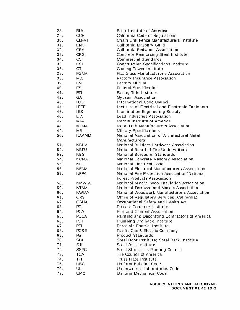
28. BIA Brick Institute of America 29. CCR California Code of Regulations 30. CLFMI Chain Link Fence Manufacturers Institute 31. CMG California Masonry Guild 32. CRA California Redwood Association 33. CRSI Concrete Reinforcing Steel Institute 34. CS Commercial Standards 35. CSI Construction Specifications Institute 36. CTI Cooling Tower Institute 37. FGMA Flat Glass Manufacturer’s Association 38. FIA Factory Insurance Association 39. FM Factory Mutual 40. FS Federal Specification 41. FTI Facing Title Institute 42. GA Gypsum Association 43. ICC International Code Council 44. IEEE Institute of Electrical and Electronic Engineers 45. IES Illumination Engineering Society 46. LIA Lead Industries Association 47. MIA Marble Institute of America 48. MLMA Metal Lath Manufacturers Association 49. MS Military Specifications 50. NAAMM National Association of Architectural Metal
Manufacturers 51. NBHA National Builders Hardware Association 52. NBFU National Board of Fire Underwriters 53. NBS National Bureau of Standards 54. NCMA National Concrete Masonry Association 55. NEC National Electrical Code 56. NEMA National Electrical Manufacturers Association 57. NFPA National Fire Protection Association/National
Forest Products Association 58. NMWIA National Mineral Wool Insulation Association 59. NTMA National Terrazzo and Mosaic Association 60. NWMA National Woodwork Manufacturer’s Association 61. ORS Office of Regulatory Services (California) 62. OSHA Occupational Safety and Health Act 63. PCI Precast Concrete Institute 64. PCA Portland Cement Association 65. PDCA Painting and Decorating Contractors of America 66. PDI Plumbing Drainage Institute 67. PEI Porcelain Enamel Institute 68. PG&E Pacific Gas & Electric Company 69. PS Product Standards 70. SDI Steel Door Institute; Steel Deck Institute 71. SJI Steel Joist Institute 72. SSPC Steel Structures Painting Council 73. TCA Tile Council of America 74. TPI Truss Plate Institute 75. UBC Uniform Building Code 76. UL Underwriters Laboratories Code 77. UMC Uniform Mechanical Code
ABBREVIATIONS AND ACRONYMS DOCUMENT 01 42 13-2
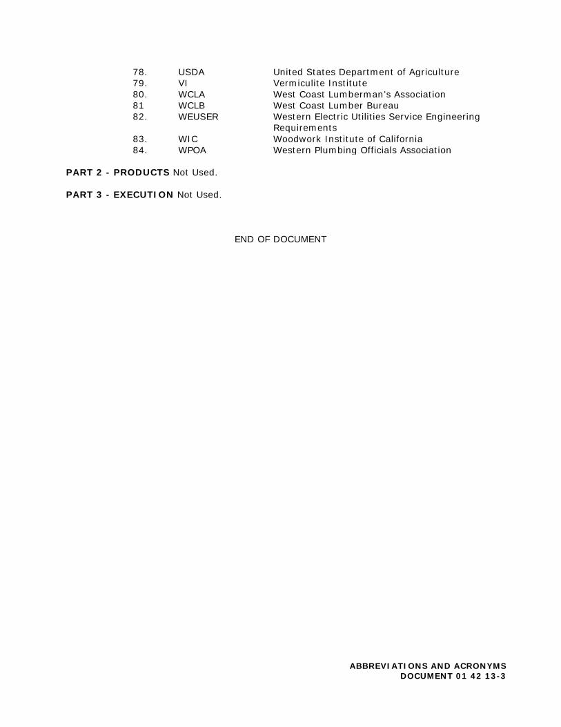
78. USDA United States Department of Agriculture 79. VI Vermiculite Institute 80. WCLA West Coast Lumberman’s Association 81 WCLB West Coast Lumber Bureau 82. WEUSER Western Electric Utilities Service Engineering
Requirements 83. WIC Woodwork Institute of California 84. WPOA Western Plumbing Officials Association
PART 2 - PRODUCTS Not Used.
PART 3 - EXECUTION Not Used.
END OF DOCUMENT
ABBREVIATIONS AND ACRONYMS DOCUMENT 01 42 13-3

DOCUMENT 01 42 16
DEFINITIONS PART 1 - GENERAL 1.01 RELATED DOCUMENTS AND PROVISION All Contract Documents should be reviewed for applicable provisions related to the provisions in this document, including without limitation:
A. General Conditions including without limitation, Definitions; B. Special Conditions.
1.02 QUALITY ASSURANCE:
A. For products or workmanship specified by association, trade, or Federal Standards, Contractor shall comply with requirements of the standard, except when more rigid requirements are specified in the Contract Documents, or are required by applicable codes.
B. Contractor shall conform to current reference standard publication date in
effect on the date of bid opening.
C. Contractor shall obtain copies of standards unless specifically required not to by the Contract Documents.
D. Contractor shall maintain a copy of all standards at jobsite during submittals,
planning, and progress of the specific Work, until final completion, unless specifically required not to by the Contract Documents.
E. Should specified reference standards conflict with Contract Documents,
Contractor shall request clarification from the District and./or the Architect before proceeding.
F. The contractual relationship of the parties to the Contract shall not be altered
from the contractual relationship as indicated in the Contract Documents by mention or inference otherwise in any referenced document.
G. Governing Codes shall be as shown in the Contract Documents including,
without limitation, the Specifications.
END OF DOCUMENT
DEFINITIONS DOCUMENT 01 42 16-1
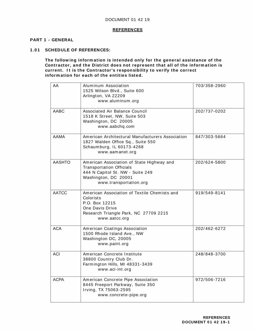
DOCUMENT 01 42 19
REFERENCES PART 1 - GENERAL 1.01 SCHEDULE OF REFERENCES:
The following information is intended only for the general assistance of the Contractor, and the District does not represent that all of the information is current. It is the Contractor’s responsibility to verify the correct information for each of the entities listed.
AA Aluminum Association 1525 Wilson Blvd., Suite 600 Arlington, VA 22209
www.aluminum.org
703/358-2960
AABC Associated Air Balance Council 1518 K Street, NW, Suite 503 Washington, DC 20005
www.aabchq.com
202/737-0202
AAMA American Architectural Manufacturers Association 1827 Walden Office Sq., Suite 550 Schaumburg, IL 60173-4268
www.aamanet.org
847/303-5664
AASHTO American Association of State Highway and Transportation Officials 444 N Capitol St. NW - Suite 249 Washington, DC 20001
www.transportation.org
202/624-5800
AATCC American Association of Textile Chemists and Colorists P.O. Box 12215 One Davis Drive Research Triangle Park, NC 27709 2215
www.aatcc.org
919/549-8141
ACA American Coatings Association 1500 Rhode Island Ave., NW Washington DC, 20005
www.paint.org
202/462-6272
ACI American Concrete Institute 38800 Country Club Dr. Farmington Hills, MI 48331-3439
www.aci-int.org
248/848-3700
ACPA American Concrete Pipe Association 8445 Freeport Parkway, Suite 350 Irving, TX 75063-2595
www.concrete-pipe.org
972/506-7216
REFERENCES DOCUMENT 01 42 19-1
ADC Air Diffusion Council 1901 N. Roselle Road, Suite 800 Schaumburg, Illinois 60195
www.flexibleduct.org
847/706-6750
AF&PA American Forest and Paper Association 1111 Nineteenth Street, NW, Suite 800 Washington, DC 20036
www.afandpa.org
202/463-2700
AGA American Gas Association 400 North Capitol Street, NW Washington, DC 20001
www.aga.org
202/824-7000
AGC Associate General Contractors of America 2300 Wilson Blvd., Suite 400 Arlington, VA 22201
www.agc.org
703/548-3118
AHA American Hardboard Association 1210 West Northwest Highway Palatine, IL 60067
domensino.com/AHA/default.htm
847/934-8800
AI Asphalt Institute 2696 Research Park Drive Lexington, KY 40511-8480
www.asphaltinstitute.org
859/288-4960
AIA The American Institute of Architects 1735 New York Ave., NW Washington, DC 20006-5292
www.aia.org
202/626-7300
AISC American Institute of Steel Construction One East Wacker Drive Suite 700 Chicago, IL 60601-1802
www.aisc.org
312.670.2400
AIA American Insurance Association (formerly the National Board of Fire Underwriters) 2101 L Street, NW, Suite 400 Washington, DC 20037
www.aiadc.org
202/828-7100
AISI American Iron and Steel Institute 25 Massachusetts Ave., NW, Suite 800 Washington, DC 20001
www.steel.org
202/452.7100
AITC American Institute of Timber Construction 7012 S. Revere Parkway Suite 140 Centennial, CO 80112
www.aitc-glulam.org
303/792.9559
REFERENCES DOCUMENT 01 42 19-2

ALI Associated Laboratories, Inc. P.O. Box 152837 Dallas, TX 75315
www.assoc-labs.com
214/565-0593
ALSC American Lumber Standards Committee, Inc. P.O. Box 210 Germantown, MD 20875
www.alsc.org
301/972-1700
AMCA Air Movement and Control Association International, Inc. 30 W. University Drive Arlington Heights, IL 60004
www.amca.org
847/394-0150
ANLA American Nursery & Landscape Association 1200 G Street NW, Suite 800 Washington, DC 20005
www.anla.org
202/789-2900
ANSI American National Standards Institute 1899 L Street, NW, 11th Floor Washington, DC, 20036
www.ansi.org
202/293.8020
APA APA-The Engineered Wood Association 7011 S. 19th Street Tacoma, WA 98466-5333
www.apawood.org
253/565-6600
APA Architectural Precast Association 6710 Winkler Road, Suite 8 Fort Myers, Florida 33919
www.archprecast.org
239/454-6989
ARI Air Conditioning and Refrigeration Institute 4100 N. Fairfax Drive, Suite 200 Arlington, VA 22203
www.lightindustries.com/ARI
703/524-8800
ARMA Asphalt Roofing Manufacturers Association Public Information Department 750 National Press Building 529 14th Street, NW Washington, DC 20045
www.asphaltroofing.org
202/591-2450
ASA The Acoustical Society of America ASA Office Manager Suite 1NO1 2 Huntington Quadrangle Melville, NY 11747-4502
http://asa.aip.org
516/576-2360
REFERENCES DOCUMENT 01 42 19-3
ASCE American Society of Civil Engineers 1801 Alexander Bell Drive Reston, VA 20191
www.asce.org
800/548-2723 703/295-6300
ASHRAE American Society of Heating, Refrigerating and Air Conditioning Engineers 1791 Tullie Circle, NE Atlanta, GA 30329-2305
www.ashrae.org
800/527-4723 404/636-8400
ASLA American Society of Landscape Architects 636 Eye Street, NW Washington, DC 20001-3736
www.asla.org
202/898-2444
ASME American Society of Mechanical Engineers Three Park Avenue New York, NY 10016-5990
www.asme.org
800/434-2763
ASPE American Society of Plumbing Engineers 2980 S River Rd. Des Plaines, IL 60018
http://aspe.org
847/296-0002
ASQ American Society for Quality P.O. Box 3005 Milwaukee, WI 53201-3005
or 600 North Plankinton Avenue Milwaukee, WI 53203
http://asq.org
800/248-1946 414/272-8575
ASSE American Society of Sanitary Engineering 901 Canterbury, Suite A Westlake, Ohio 44145
www.asse-plumbing.org
440/835-3040
ASTM ASTM International 100 Barr Harbor Drive PO Box C700 West Conshohocken, PA, 19428-2959
www.astm.org
610/832-9500
AWCI Association of the Wall and Ceiling Industry 513 West Broad Street, Suite 210 Falls Church, VA 22046
www.awci.org
703/538-1600
AWPA American Wood Protection Association P.O. Box 361784 Birmingham, AL 35236-1784
www.awpa.com
205/733-4077
REFERENCES DOCUMENT 01 42 19-4
AWPI American Wood Preservers Institute 2750 Prosperity Ave. Suite 550 Fairfax, VA 22031-4312
www.arcat.com
800/356-AWPI 703/204-0500
AWS American Welding Society 8669 Doral Boulevard, Suite 130 Doral, Florida 33166
www.aws.org
800/443-9353 305/443-9353
AWI Architectural Woodwork Institute 46179 Westlake Drive, Suite 120 Potomac Falls, VA 20165-5874
www.awinet.org
571/323-3636
AWWA American Water Works Association 6666 West Quincy Avenue Denver, CO 80235
www.awwa.org
800/926-7337 303/794 7711
BHMA Builders Hardware Manufacturers Association 355 Lexington Avenue, 15th floor New York, NY 10017
www.buildershardware.com
212/297-2122
BIA The Brick Industry Association 1850 Centennial Park Drive, Suite 301 Reston, VA 20191
www.gobrick.com
703/620-0010
CGA Compressed Gas Association 14501 George Carter Way, Suite 103 Chantilly VA 20151-2923
www.cganet.com
703/788-2700
CISCA Ceilings & Interior Systems Construction Association 1010 Jorie Blvd, Suite 30 Oak Brook, IL 60523
www.cisca.org
630/584-1919
CISPI Cast Iron Soil Pipe Institute 1064 Delaware Avenue SE Atlanta, GA 30316
www.cispi.org
404/622-0073
CLFMI Chain Link Fence Manufacturers Institute 10015 Old Columbia Road, Suite B-215 Columbia, MD 21046
www.associationsites.com/main-pub.cfm?usr=clfma
410/290-6267
CPA Composite Panel Association 19465 Deerfield Avenue, Suite 306 Leesburg, VA 20176
www.compositepanel.org
703/724-1128
REFERENCES DOCUMENT 01 42 19-5

CPSC Consumer Product Safety Commission 4330 East West Highway Bethesda, MD 20814
www.cpsc.gov
301/504-7923 800/638-2772
CRA California Redwood Association 405 Enfrente Drive, Suite 200 Novato, CA 94949
www.calredwood.org
415/382-0662
CRI Carpet and Rug Institute P.O. Box 2048 Dalton, Georgia 30722-2048
www.carpet-rug.org
706/278-3176
CRSI Concrete Reinforcing Steel Institute 933 N. Plum Grove Road Schaumburg, IL 60173 4758
www.crsi.org
847/517-1200
CSI The Construction Specifications Institute 110 South Union Street, Suite 100 Alexandria VA 22314
www.csinet.org
800/689-2900
CTIOA Ceramic Tile Institute of America 12061 Jefferson Blvd. Culver City, CA 90230-6219
www.ctioa.org
310/574-7800
DHI Door and Hardware Institute (formerly National Builders Hardware Association) 14150 Newbrook Dr. Chantilly, VA 20151
www.dhi.org
703/222-2010
DIPRA Ductile Iron Pipe Research Association 2000 2nd Avenue, South Suite 429 Birmingham, AL 35233
www.dipra.org
205/402-8700
DOC U.S. Department of Commerce 1401 Constitution Ave., NW Washington, D.C. 20230
www.commerce.gov
202/482-2000
DOT U.S. Department of Transportation 1200 New Jersey Avenue, SE Washington, DC 20590
www.dot.gov
855/368-4200
EJMA Expansion Joint Manufacturers Association, Inc. 25 North Broadway Tarrytown, NY 10591
www.ejma.org
914/332-0040
REFERENCES DOCUMENT 01 42 19-6

EPA Environmental Protection Agency Ariel Rios Building 1200 Pennsylvania Avenue, N.W. Washington, DC 20460
www.epa.gov
202/272-0167
FCICA Floor Covering Installation Contractors Association 7439 Millwood Drive West Bloomfield, MI 48322
www.fcica.com
248/661-5015 877/TO-FCICA
FM Global Factory Mutual Insurance Company Mary Breighner Global Practice Leader Education, Public Entities, Health Care FM Global 9 Woodcrest Court Cincinnati, OH 45246
www.fmglobal.com
513/742-9516
FS General Services Administration (GSA) Index of Federal Specifications, Standards and Commercial Item Descriptions 470 East L’Enfant Plaza, SW, Suite 8100 Washington, DC 20407
www.gsa.gov
202/619-8925
GA The Gypsum Association 6525 Belcrest Road, Suite 480 Hyattsville, MD 20782
www.gypsum.org
301/277-8686
GANA Glass Association of North America 800 SW Jackson St., Suite 1500 Topeka, KS 66612-1200
www.glasswebsite.com
785/271-0208
HMA Hardwood Manufacturers Association 665 Rodi Road, Suite 305 Pittsburgh, PA 15235
http://hmamembers.org
412/244-0440
HPVA Hardwood Plywood & Veneer Association 1825 Michael Faraday Drive Reston, Virginia 20190
www.hpva.org
703/435-2900
REFERENCES DOCUMENT 01 42 19-7
IAPMO International Association of Plumbing and Mechanical Officials (formerly the Western Plumbing Officials Association) 4755 E. Philadelphia St. Ontario, CA 91761
www.iapmo.org
909/472-4100
ICC International Code Council 500 New Jersey Avenue, NW, 6th Floor Washington, DC 20001
www.iccsafe.org
888/422-7233
IEEE Institute of Electrical and Electronics Engineers 3 Park Avenue, 17th Floor New York, NY 10016-5997
www.ieee.org
212/419-7900
IES Illuminating Engineering Society 120 Wall Street, Floor 17 New York, NY 10005-4001
www.ies.org
212/248-5000
ITRK Intertek Testing Services 3933 US Route 11 Cortland, NY 13045
www.intertek.com
607/753-6711
MCAA Mechanical Contractors Association of America 1385 Piccard Drive Rockville, MD 20850
www.mcaa.org
301/869-5800
MIA Marble Institute of America 28901 Clemens Rd, Ste 100 Cleveland, OH 44145
www.marble-institute.com
440/250-9222
MMPA (formerly WMMPA)
Moulding & Millwork Producers Association (formerly Wood Moulding & Millwork Producers Association) 507 First Street Woodland, CA 95695
www.wmmpa.com
530/661-9591 800/550-7889
MSS Manufacturers Standardization Society (MSS) of the Valve and Fittings Industry 127 Park Street, NE Vienna, VA 22180-4602
http://mss-hq.org
703/281-6613
NAAMM National Association of Architectural Metal Manufacturers 800 Roosevelt Rd. Bldg. C, Suite 312 Glen Ellyn, IL 60137
www.naamm.org
630/942-6591
REFERENCES DOCUMENT 01 42 19-8

NAIMA North American Insulation Manufacturers Association 44 Canal Center Plaza, Suite 310 Alexandria, VA 22314
www.naima.org
703/684-0084
NAPA National Asphalt Pavement Association 5100 Forbes Blvd. Lanham, MD USA 20706-4407
www.asphaltpavement.org
888/468-6499 301/731-4748
NCSPA National Corrugated Steel Pipe Association 14070 Proton Road, Suite 100 LB9 Dallas, TX 75244
www.ncspa.org
972/850-1907
NCMA National Concrete Masonry Association 13750 Sunrise Valley Drive Herndon, VA 20171-4662
www.ncma.org
703/713-1900
NEBB National Environmental Balancing Bureau 8575 Grovemont Circle Gaithersburg, MD 20877
www.nebb.org
301/977-3698
NECA National Electrical Contractors Association 3 Bethesda Metro Center, Suite 1100 Bethesda, MD 20814
www.necanet.org
301/657-3110
National Electrical Manufacturers Association 1300 North 17th Street, Suite 1752 Rosslyn, Virginia 22209
www.nema.org
703/841-3200
NEII National Elevator Industry, Inc. 1677 County Route 64 P.O. Box 838 Salem, New York 12865-0838
www.neii.org
518/854-3100
NFPA National Fire Protection Association 1 Batterymarch Park Quincy, Massachusetts USA 02169-7471
www.nfpa.org
617/770-3000
NHLA National Hardwood Lumber Association PO Box 34518 Memphis, TN 38184
www.nhla.com
901/377-1818
REFERENCES DOCUMENT 01 42 19-9
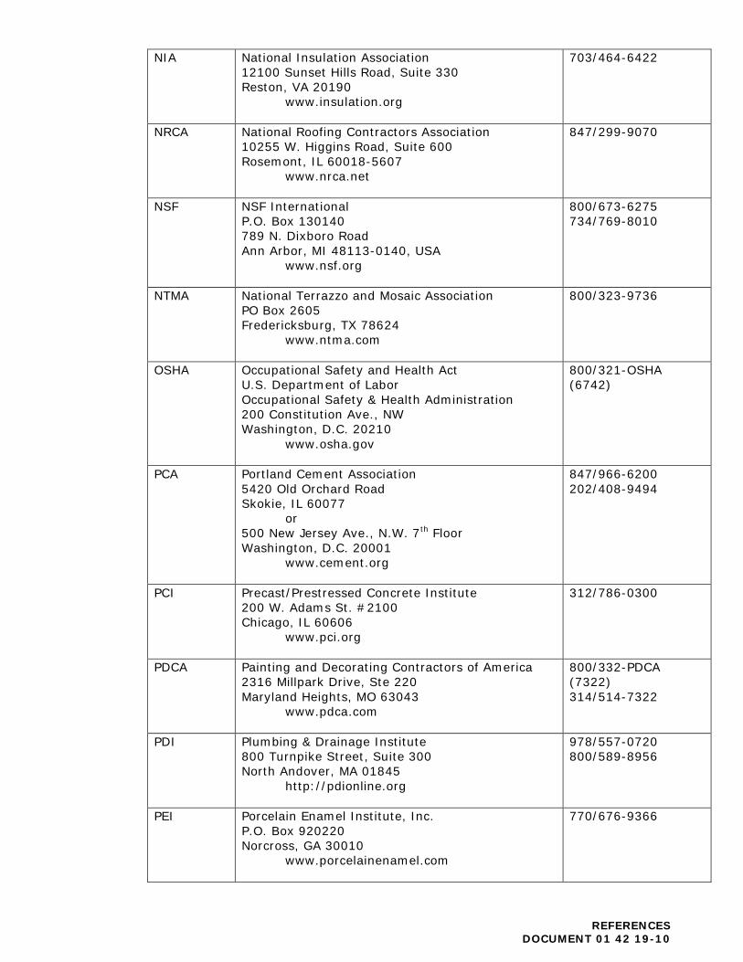
NIA National Insulation Association 12100 Sunset Hills Road, Suite 330 Reston, VA 20190
www.insulation.org
703/464-6422
NRCA National Roofing Contractors Association 10255 W. Higgins Road, Suite 600 Rosemont, IL 60018-5607
www.nrca.net
847/299-9070
NSF NSF International P.O. Box 130140 789 N. Dixboro Road Ann Arbor, MI 48113-0140, USA
www.nsf.org
800/673-6275 734/769-8010
NTMA National Terrazzo and Mosaic Association PO Box 2605 Fredericksburg, TX 78624
www.ntma.com
800/323-9736
OSHA Occupational Safety and Health Act U.S. Department of Labor Occupational Safety & Health Administration 200 Constitution Ave., NW Washington, D.C. 20210
www.osha.gov
800/321-OSHA (6742)
PCA Portland Cement Association 5420 Old Orchard Road Skokie, IL 60077
or 500 New Jersey Ave., N.W. 7th Floor Washington, D.C. 20001
www.cement.org
847/966-6200 202/408-9494
PCI Precast/Prestressed Concrete Institute 200 W. Adams St. #2100 Chicago, IL 60606
www.pci.org
312/786-0300
PDCA Painting and Decorating Contractors of America 2316 Millpark Drive, Ste 220 Maryland Heights, MO 63043
www.pdca.com
800/332-PDCA (7322) 314/514-7322
PDI Plumbing & Drainage Institute 800 Turnpike Street, Suite 300 North Andover, MA 01845
http://pdionline.org
978/557-0720 800/589-8956
PEI Porcelain Enamel Institute, Inc. P.O. Box 920220 Norcross, GA 30010
www.porcelainenamel.com
770/676-9366
REFERENCES DOCUMENT 01 42 19-10
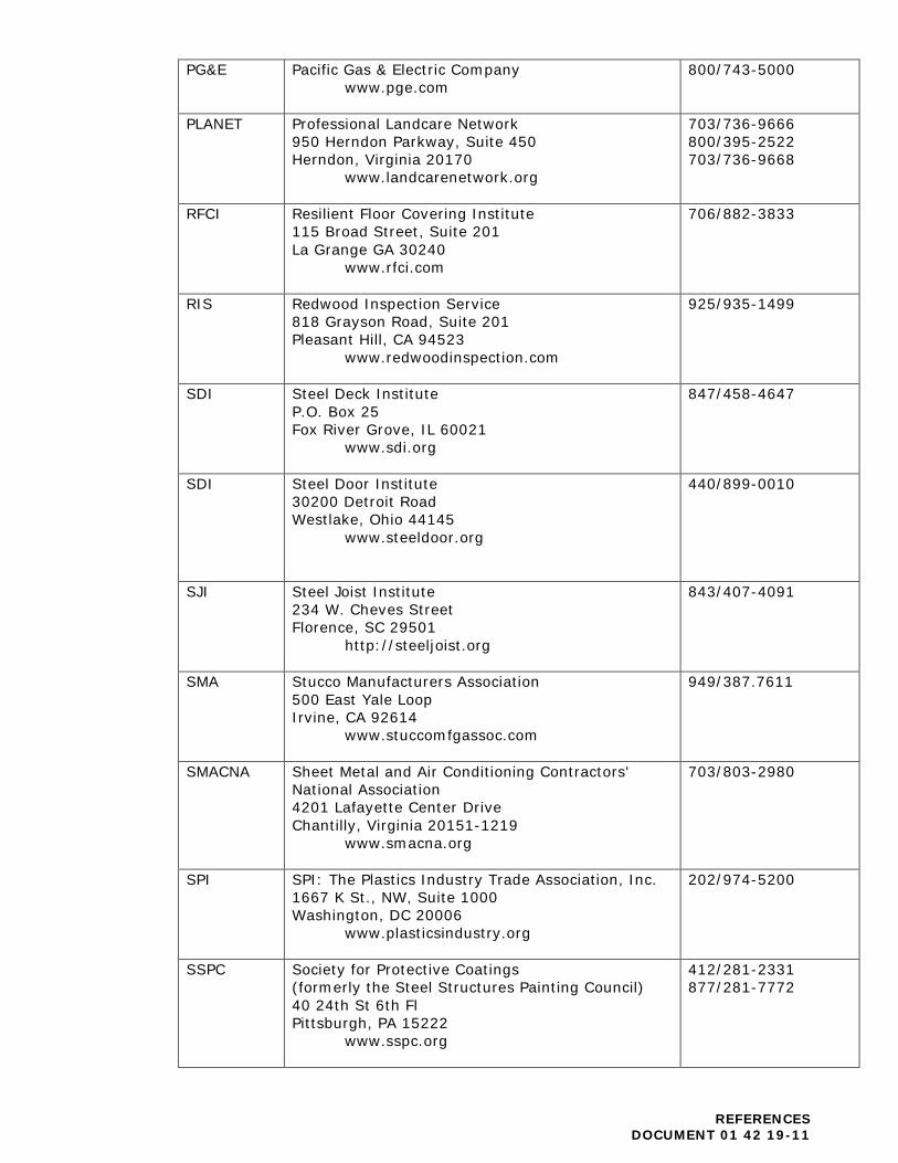
PG&E Pacific Gas & Electric Company www.pge.com
800/743-5000
PLANET Professional Landcare Network 950 Herndon Parkway, Suite 450 Herndon, Virginia 20170
www.landcarenetwork.org
703/736-9666 800/395-2522 703/736-9668
RFCI Resilient Floor Covering Institute 115 Broad Street, Suite 201 La Grange GA 30240
www.rfci.com
706/882-3833
RIS Redwood Inspection Service 818 Grayson Road, Suite 201 Pleasant Hill, CA 94523
www.redwoodinspection.com
925/935-1499
SDI Steel Deck Institute P.O. Box 25 Fox River Grove, IL 60021
www.sdi.org
847/458-4647
SDI Steel Door Institute 30200 Detroit Road Westlake, Ohio 44145
www.steeldoor.org
440/899-0010
SJI Steel Joist Institute 234 W. Cheves Street Florence, SC 29501
http://steeljoist.org
843/407-4091
SMA Stucco Manufacturers Association 500 East Yale Loop Irvine, CA 92614
www.stuccomfgassoc.com
949/387.7611
SMACNA Sheet Metal and Air Conditioning Contractors' National Association 4201 Lafayette Center Drive Chantilly, Virginia 20151-1219
www.smacna.org
703/803-2980
SPI SPI: The Plastics Industry Trade Association, Inc. 1667 K St., NW, Suite 1000 Washington, DC 20006
www.plasticsindustry.org
202/974-5200
SSPC Society for Protective Coatings (formerly the Steel Structures Painting Council) 40 24th St 6th Fl Pittsburgh, PA 15222
www.sspc.org
412/281-2331 877/281-7772
REFERENCES DOCUMENT 01 42 19-11
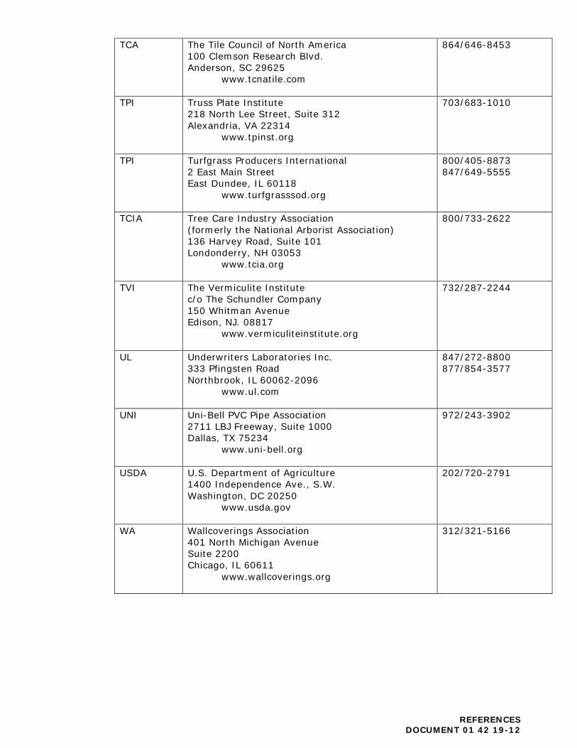
TCA The Tile Council of North America 100 Clemson Research Blvd. Anderson, SC 29625
www.tcnatile.com
864/646-8453
TPI Truss Plate Institute 218 North Lee Street, Suite 312 Alexandria, VA 22314
www.tpinst.org
703/683-1010
TPI Turfgrass Producers International 2 East Main Street East Dundee, IL 60118
www.turfgrasssod.org
800/405-8873 847/649-5555
TCIA Tree Care Industry Association (formerly the National Arborist Association) 136 Harvey Road, Suite 101 Londonderry, NH 03053
www.tcia.org
800/733-2622
TVI The Vermiculite Institute c/o The Schundler Company 150 Whitman Avenue Edison, NJ. 08817
www.vermiculiteinstitute.org
732/287-2244
UL Underwriters Laboratories Inc. 333 Pfingsten Road Northbrook, IL 60062-2096
www.ul.com
847/272-8800 877/854-3577
UNI Uni-Bell PVC Pipe Association 2711 LBJ Freeway, Suite 1000 Dallas, TX 75234
www.uni-bell.org
972/243-3902
USDA U.S. Department of Agriculture 1400 Independence Ave., S.W. Washington, DC 20250
www.usda.gov
202/720-2791
WA Wallcoverings Association 401 North Michigan Avenue Suite 2200 Chicago, IL 60611
www.wallcoverings.org
312/321-5166
REFERENCES DOCUMENT 01 42 19-12
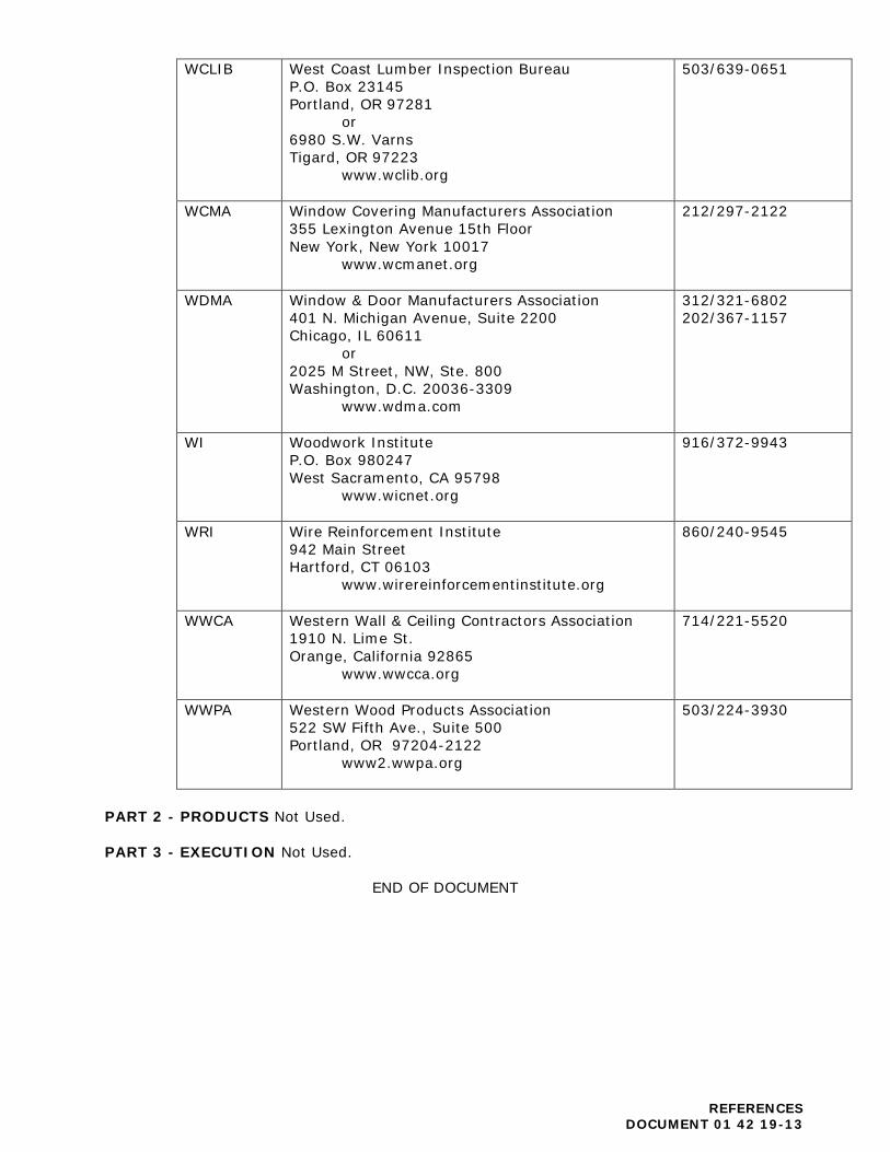
WCLIB West Coast Lumber Inspection Bureau P.O. Box 23145 Portland, OR 97281
or 6980 S.W. Varns Tigard, OR 97223
www.wclib.org
503/639-0651
WCMA Window Covering Manufacturers Association 355 Lexington Avenue 15th Floor New York, New York 10017
www.wcmanet.org
212/297-2122
WDMA Window & Door Manufacturers Association 401 N. Michigan Avenue, Suite 2200 Chicago, IL 60611
or 2025 M Street, NW, Ste. 800 Washington, D.C. 20036-3309
www.wdma.com
312/321-6802 202/367-1157
WI Woodwork Institute P.O. Box 980247 West Sacramento, CA 95798
www.wicnet.org
916/372-9943
WRI Wire Reinforcement Institute 942 Main Street Hartford, CT 06103
www.wirereinforcementinstitute.org
860/240-9545
WWCA Western Wall & Ceiling Contractors Association 1910 N. Lime St. Orange, California 92865
www.wwcca.org
714/221-5520
WWPA Western Wood Products Association 522 SW Fifth Ave., Suite 500 Portland, OR 97204-2122
www2.wwpa.org
503/224-3930
PART 2 - PRODUCTS Not Used. PART 3 - EXECUTION Not Used.
END OF DOCUMENT
REFERENCES DOCUMENT 01 42 19-13
DOCUMENT 01 43 00
MATERIALS AND EQUIPMENT PART 1 - GENERAL 1.01 RELATED DOCUMENTS AND PROVISIONS
All Contract Documents should be reviewed for applicable provisions related to the provisions in this document, including without limitation:
A. General Conditions, including, without limitation, Purchase of Materials and
Equipment; B. Special Conditions;
C. Imported Materials Certification.
1.02 MATERIAL AND EQUIPMENT
A. Only items approved by the District and/or Architect shall be used. B. Contractor shall submit lists of products and other product information in
accordance with the Contract Documents, including, without limitation, the provisions regarding the submittals.
1.03 MATERIAL AND EQUIPMENT COLORS
A. The District and/or Architect will provide a schedule of colors. B. No individual color selections will be made until after approval of all pertinent
materials and equipment and after receipt of appropriate samples in accordance with the Contract Documents, including, without limitation, the provisions regarding the submittals.
C. Contractor shall request priority in writing for any item requiring advance
ordering to maintain the approved Construction Schedule. 1.04 DELIVERY, STORAGE, AND HANDLING
A. Contractor shall deliver manufactured materials in original packages, containers, or bundles (with seals unbroken), bearing name or identification mark of manufacturer.
B. Contractor shall deliver fabrications in as large assemblies as practicable;
where specified as shop-primed or shop-finished, package or crate as required to preserve such priming or finish intact and free from abrasion.
C. Contractor shall store materials in such a manner as necessary to properly
protect them from damage. Materials or equipment damaged by handling, weather, dirt, or from any other cause will not be accepted.
MATERIALS AND EQUIPMENT DOCUMENT 01 43 00-1
D. Materials are not acceptable, that have been warehoused for long periods of time, stored or transported in improper environment, improperly packaged, inadequately labeled, poorly protected, excessively shipped, deviated from normal distribution pattern, or reassembled.
E. Contractor shall store material so as to cause no obstructions of sidewalks,
roadways, and underground services. Contractor shall protect material and equipment furnished under Contract.
F. Contractor may store materials on Site with prior written approval by the
District, all material shall remain under Contractor's control and Contractor shall remain liable for any damage to the materials. Should the Project Site not have storage area available, the Contractor shall provide for off-site storage at a bonded warehouse and with appropriate insurance coverage at no cost to District.
G. When any room in Project is used as a shop or storeroom, the Contractor
shall be responsible for any repairs, patching, or cleaning necessary due to that use. Location of storage space shall be subject to prior written approval by District.
PART 2 - PRODUCTS 2.01 MANUFACTURERS
A. Manufacturers listed in various sections of Contract Documents are names of those manufacturers that are believed to be capable of supplying one or more of items specified therein.
B. The listing of a manufacturer does not imply that every product of that
manufacturer is acceptable as meeting the requirements of the Contract Documents.
2.02 FACILITIES AND EQUIPMENT
Contractor shall provide, install, maintain, and operate a complete and adequate facility for handling, the execution, disposal, and distribution of material and equipment as required for proper and timely performance of Work connected with Contract.
2.03 MATERIAL REFERENCE STANDARDS
Where material is specified solely by reference to “standard specifications” and if requested by District, Contractor shall submit for review data on actual material proposed to be incorporated into Work of Contract listing name and address of vendor, manufacturer, or producer, and trade or brand names of those materials, and data substantiating compliance with standard specifications.
MATERIALS AND EQUIPMENT DOCUMENT 01 43 00-2

PART 3 - EXECUTION 3.01 WORKMANSHIP
A. Where not more specifically described in any other Contract Documents, workmanship shall conform to methods and operations of best standards and accepted practices of trade or trades involved and shall include items of fabrication, construction, or installation regularly furnished or required for completion (including finish and for successful operation, as intended).
B. Work shall be executed by tradespersons skilled in their respective lines of
Work. When completed, parts shall have been durably and substantially built and present a neat appearance.
3.02 COORDINATION
A. Contractor shall coordinate installation of Work so as to not interfere with installation of others. Adjustment or rework because of Contractor’s failure to coordinate will be at no additional cost to District.
B. Contractor shall examine in-place work for readiness, completeness, fitness to
be concealed or to receive other work, and in compliance with Contract Documents. Concealing or covering Work constitutes acceptance of additional cost which will result should in-place Work be found unsuitable for receiving other Work or otherwise deviating from the requirements of the Contract Documents.
3.03 COMPLETENESS
Contractor shall provide all portions of the Work, unless clearly stated otherwise, installed complete and operational with all elements, accessories, anchorages, utility connections, etc., in manner to assure well-balanced performance, in accordance with manufacturer's recommendations and by Contract Documents. For example, electric water coolers require water, electricity, and drain services; roof drains require drain system; sinks fit within countertop, etc. Terms such as “installed complete,” “operable condition,” “for use intended,” “connected to all utilities,” “terminate with proper cap,” “adequately anchored,” “patch and refinish,” “to match similar,” should be assumed to apply in all cases, except where completeness of functional or operable condition is specifically stated as not required.
3.04 APPROVED INSTALLER OR APPLICATOR
Installation by a manufacturer’s approved installer or applicator is an understood part of Specifications and only approved installer or applicator is to provide on-site Work where specified manufacturer has on-going program of approving (i.e. certifying, bonding, re-warranting) installers or applicators. Newly established relationships between a manufacturer and an installer or applicator who does not have other approved applicator work in progress or completed is not approved for this Project.
MATERIALS AND EQUIPMENT DOCUMENT 01 43 00-3
3.05 MANUFACTURER'S RECOMMENDATIONS
All installations shall be in accordance with manufacturer's published recommendations and specific written directions of manufacturer's representative. Should Contract Documents differ from recommendations of manufacturer or directions of his representative, Contractor shall analyze differences, make recommendations to the District and the Architect in writing, and shall not proceed until interpretation or clarification has been issued by the District and/or the Architect.
END OF DOCUMENT
MATERIALS AND EQUIPMENT DOCUMENT 01 43 00-4
DOCUMENT 01 45 00
QUALITY CONTROL PART 1 - GENERAL 1.01 RELATED DOCUMENTS AND PROVISIONS: All Contract Documents should be reviewed for applicable provisions related to the provisions in this document, including without limitation:
A. General Conditions, including, without limitation, Inspector, Inspections and Tests, Uncovering of Work and Non-conforming of Work and Correction of Work;
B. Special Conditions.
1.02 RELATED CODES:
A. The Work is governed by requirements of Title 24, California Code of Regulations (“CCR”), and the Contractor shall keep a copy of these available at the job Site for ready reference during construction.
B. The Division of the State Architect (“DSA”) shall be notified at or before the
start of construction. 1.03 OBSERVATION AND SUPERVISION:
A. The District and Architect or their appointed representatives will review the Work and the Contractor shall provide facilities and access to the Work at all times as required to facilitate this review. Administration by the Architect and any consulting Structural Engineer will be in accordance with applicable regulations, including, without limitation, CCR, Part 1, Title 24, Section 4-341.
B. One or more Project Inspector(s) approved by DSA and employed by or in
contract with the District, referred to hereinafter as the “Project Inspector”, will observe the work in accordance with CCR, Part 1, Title 24, Sections 4-333(b) and 4-342:
(1) The Project Inspector shall have access to the Work wherever it is in
preparation or progress for ascertaining that the Work is in accordance with the Contract Documents and all applicable code sections.. The Contractor shall provide facilities and access as required and shall provide assistance for sampling or measuring materials.
(2) The Project Inspector will notify the District and Architect and call the
attention of the Contractor to any observed failure of Work or material to conform to Contract Documents.
(3) The Project Inspector shall observe and monitor all testing and inspection
activities required.
QUALITY CONTROL DOCUMENT 00 45 00-1

The Contractor shall conform with all applicable laws as indicated in the Contract Documents, including, without limitation, to CCR, Part 1, Title 24, Section 4-343. The Contractor shall supervise and direct the Work and maintain a competent superintendent on the job who is authorized to act in all matters pertaining to the Work. The Contractor's superintendent shall also inspect all materials, as they arrive, for compliance with the Contract Documents. Contractor shall reject defective Work or materials immediately upon delivery or failure of the Work or material to comply with the Contract Documents. The Contractor shall submit verified reports as indicated in the Contract Documents, including, without limitation, the Specifications and as required by Part 1, Title 24, Section 4-336.
1.04 TESTING AGENCIES:
A. Testing agencies and tests shall be in conformance with the General Documents and the requirements of Part 1, Title 24, Section 4- 335.
B. Testing and inspection in connection with earthwork shall be under the direction
of the District's consulting soils engineer, if any, referred to hereinafter as the "Soils Engineer."
C. Testing and inspection of construction materials and workmanship shall be
performed by a qualified laboratory, referred to hereinafter as the "Testing Laboratory." The Testing Laboratory shall be under direction of an engineer registered in the State of California, shall conform to requirements of ASTM E329, and shall be employed by or in contract with the District.
1.05 TESTS AND INSPECTIONS:
A. The Contractor shall be responsible for notifying the District and Project Inspector of all required tests and inspections. Contractor shall notify the District and Project Inspector at least seventy-two hours (72) hours in advance of performing any Work requiring testing or inspection.
B. The Contractor shall provide access to Work to be tested and furnish incidental
labor, equipment, and facilities to facilitate all inspections and tests.
C. The District will pay for first inspections and tests required by the “CCR”, and other inspections or tests that the District and/or the Architect may direct to have made, including the following principal items:
(1) Tests and observations for earthwork and paving. (2) Tests for concrete mix designs, including tests of trial batches.
(3) Tests and inspections for structural steel work.
(4) Field tests for framing lumber moisture content.
(5) Additional tests directed by the District that establish that materials and
installation comply with the Contract Documents.
(6) Test and observation of welding and expansion anchors.
QUALITY CONTROL DOCUMENT 00 45 00-2
D. The District may at its discretion, pay and back charge the Contractor for:
(1) Retests or reinspections, if required, and tests or inspections required
due to Contractor error or lack of required identifications of material.
(2) Uncovering of work in accordance with Contract Documents.
(3) Testing done on weekends, holidays, and overtime will be chargeable to the Contractor for the overtime portion.
(4) Testing done off Site.
E. Testing and inspection reports and certifications:
(1) If initially received by Contractor, Contractor shall provide to each of the
following a copy of the agency or laboratory report of each test or inspection or certification.
a. The District; b. The Construction Manager, if any;
c. The Architect;
d. The Consulting Engineer, if any;
e. Other engineers on the Project, as appropriate;
f. The Project Inspector; and
g. The Contractor.
(2) When the test or inspection is one required by the CCR, a copy of the
report shall also be provided to the DSA. PART 2 - PRODUCTS 2.01 TYPE OF TEST AND INSPECTIONS:
A. Slump Test
ASTM C 143
QUALITY CONTROL DOCUMENT 00 45 00-3

B. Concrete Tests
Testing agency shall test concrete used in the work per the following paragraphs:
(1) Compressive Strength:
a. Minimum number of tests required: One (1) set of three (3)
cylinders for each 100 cubic yards (Sec. 2604(h) 01) of concrete or major fraction thereof, placed in one (1) day. See Title 24, Section 2605(g).
b. Two cylinders of each set shall be tested at twenty-eight (28)
days. One (1) cylinder shall be held in reserve and tested only when directed by the Architect or District.
c. Concrete shall test the minimum ultimate compressive strength in
28 days, as specified on the structural drawings.
d. In the event that the twenty-eight (28) day test falls below the minimum specified strength, the effective concrete in place shall be tested by taking cores in accordance with UBC Standard No. 26-13 and tested as required for cylinders.
e. In the event that the test on core specimens falls below the
minimum specified strength, the concrete will be deemed defective and shall be removed and replaced upon such direction of the Architect, and in a manner acceptable to the Division of the State Architect.
C. Reinforcing, Steel
D. Structural Steel Per Title 24 and as noted:
(1) Material: Steel per Table in Title 24, Section 2712. (2) Qualification of Welders (UBC Std. 27-6).
(3) Shop fabrication (Section 2712(d). Structural steel only).
(4) Shop and field welding (Section 2712(e)).
PART 3 - EXECUTION Not Used.
END OF DOCUMENT
QUALITY CONTROL DOCUMENT 00 45 00-4
DOCUMENT 01 50 00
TEMPORARY FACILITIES AND CONTROLS PART 1 – GENERAL 1.01 RELATED DOCUMENTS AND PROVISIONS:
All Contract Documents should be reviewed for applicable provisions related to the provisions in this document, including without limitation:
A. General Conditions; B. Special Conditions;
C. Site Standards.
1.02 TEMPORARY UTILITIES:
A. Electric Power and Lighting
(1) Contractor will pay for power during the course of the Work. To the extent power is available in the building(s) or on the Site, Contractor may use the District’s existing utilities by making prearranged payments to the District for the utilities used by Contractor and all Subcontractors. Contractor shall be responsible for providing temporary facilities required to deliver that power service from its existing location in the building(s) or on the Site to point of intended use.
(2) Contractor shall verify characteristics of power available in building(s)
or on the Site. Contractor shall take all actions required to make modifications where power of higher voltage or different phases of current are required. Contractor shall be fully responsible for providing that service and shall pay all costs required therefor.
(3) Contractor shall furnish, wire for, install, and maintain temporary
electrical lights wherever it is necessary to provide illumination for the proper performance and/or observation of the Work: a minimum of 20 foot-candles for rough work and 50 foot-candles for finish work.
(4) Contractor shall be responsible for maintaining existing lighting levels
in the project vicinity should temporary outages or service interruptions occur.
TEMPORARY FACILITIES AND CONTROLS DOCUMENT 01 50 00-1

B. Heat and Ventilation
(1) Contractor shall provide temporary heat to maintain environmental conditions to facilitate progress of the Work, to meet specified minimum conditions for the installation and curing of materials, and to protect materials and finishes from damage due to improper temperature and humidity conditions. Portable heaters shall be standard units complete with controls.
(2) Contractor shall provide forced ventilation and dehumidification, as
required, of enclosed areas for proper installation and curing of materials, to disperse humidity, and to prevent hazardous accumulations of dust, fumes, vapors, and gases.
(3) Contractor shall pay the costs of installation, maintenance, operation,
and removal of temporary heat and ventilation, including costs for fuel consumed, required for the performance of the Work.
C. Water
(1) Contractor will pay for water during the course of the Work. To the
extent water is then available in the building(s) or on the Site, Contractor may use the District’s existing utilities by making prearranged payments to the District for the utilities used by Contractor and all Subcontractors. Contractor shall be responsible for providing temporary facilities required to deliver such utility service from its existing location in the building(s) or on the Site to point of intended use.
(2) Contractor shall use backflow preventers on water lines at point of
connection to District’s water supply. Backflow preventers shall comply with requirements of Uniform Plumbing Code.
(3) Contractor shall make potable water available for human consumption.
D. Sanitary Facilities
(1) Contractor shall provide sanitary temporary facilities in no fewer
numbers than required by law and such additional facilities as may be directed by the Inspector for the use of all workers. The facilities shall be maintained in a sanitary condition at all times and shall be left at the Site until removal is directed by the Inspector or Contractor completes all other work at the Site.
(2) Use of toilet facilities in the Work under construction shall not be
permitted except by consent of the Inspector and the District.
TEMPORARY FACILITIES AND CONTROLS DOCUMENT 01 50 00-2

E. Telephone Service
(1) Contractor shall arrange with local telephone service company for telephone service for the performance of the Work. Contractor shall, at a minimum, provide in its field office one line for telephone and one line for fax machine.
(2) Contractor shall pay the costs for telephone and fax lines installation,
maintenance, service, and removal.
F. Fire Protection:
(1) Contractor shall provide and maintain fire extinguishers and other equipment for fire protection. Such equipment shall be designated for use for fire protection only and shall comply with all requirements of the California Fire, State Fire Marshall and/or its designee.
(2) Where on-site welding and burning of steel is unavoidable, Contractor
shall provide protection for adjacent surfaces.
(3) Provide Fire Watch when the fire alarm system is completely down for any length of time.
G. Trash Removal:
(1) Contractor shall provide trash removal on a timely basis.
H. Temporary Facilities:
(1) The Contractor shall provide and maintain temporary office facilities for the Owner and their use on the site, where directed by the Owner, from the beginning to the completion of the work. The office facility shall be for the exclusive use of the Project Manager, the Inspector and the Architect, and shall be secure, have environmental controls, be wind and weatherproof, furnished with sufficient window and lighting to permit the reading of blueprints, and shall have two drawing tables not less than 42” x 72” in dimensions. The facility shall include an office space for the Project Manager/Architect/Inspector of Record and a conference room. Office shall be a minimum of 10 feet by 15 feet with locking dead bolt on the door and provided with one phone and data service, 2 desks and 4 chairs, and 1 four drawer file cabinet each. Conference room shall have a conference table and chairs, fax with phone line. Phone lines shall be connected to the main line of the telephone company.
1.03 CONSTRUCTION AIDS:
A. Plant and Equipment:
(1) Contractor shall furnish, operate, and maintain a complete plant for
fabricating, handling, conveying, installing, and erecting materials and
TEMPORARY FACILITIES AND CONTROLS DOCUMENT 01 50 00-3
equipment; and for conveyances for transporting workmen. Include elevators, hoists, debris chutes, and other equipment, tools, and appliances necessary for performance of the Work.
(2) Contractor shall maintain plant and equipment in safe and efficient
operating condition. Damages due to defective plant and equipment, and uses made thereof, shall be repaired by Contractor at no expense to the District.
B. None of the District’s tools and equipment shall be used by Contractor for the
performance of the Work. 1.04 BARRIERS AND ENCLOSURES:
A. Contractor shall obtain the District's written permission for locations and types of temporary barriers and enclosures, including fire-rated materials proposed for use, prior to their installation.
B. Contractor shall provide and maintain temporary enclosures with screen to
prevent public entry and to protect persons using other buildings and portions of the Site and/or Premises, the public, and workers. Contractor shall also protect the Work and existing facilities from the elements, and adjacent construction and improvements, persons, and trees and plants from damage and injury from demolition and construction operations.
C. Contractor shall provide site access to existing facilities for persons using
other buildings and portions of the Site, the public, and for deliveries and other services and activities.
D. Tree and Plant Protection:
(1) Contractor shall preserve and protect existing trees and plants on the
Premises that are not designated or required to be removed, and those adjacent to the Premises.
(2) Contractor shall provide barriers to a minimum height of 4'-0" around
drip line of each tree and plant, around each group of trees and plants, as applicable, in the proximity of demolition and construction operations.
(3) Contractor shall not park trucks, store materials, perform Work or
cross over landscaped areas. Contractor shall not dispose of paint thinners, water from cleaning, plastering or concrete operations, or other deleterious materials in landscaped areas, storm drain systems, or sewers. Plant materials damaged as a result of the performance of the Work shall, at the option of the District and at Contractor's expense, either be replaced with new plant materials equal in size to those damaged or by payment of an amount representing the value of the damaged materials as determined by the District.
(4) Contractor shall remove soil that has been contaminated during the
performance of the Work by oil, solvents, and other materials which TEMPORARY FACILITIES AND CONTROLS DOCUMENT 01 50 00-4
could be harmful to trees and plants, and replace with good soil, at Contractor's expense.
(5) Excavation Around Trees:
(a) Excavation within drip lines of trees shall be done only where
absolutely necessary and with written permission from the District.
(b) Where trenching for utilities is required within drip lines,
tunneling under and around roots shall be by hand digging and shall be approved by the District. Main lateral roots and taproots shall not be cut. All roots 2 inches in diameter and larger shall be tunneled under and heavily wrapped with wet burlap so as to prevent scarring or excessive drying. Smaller roots that interfere with installation of new work may be cut with prior approval by the District. Roots must first be cut with a Vermeer, or equivalent, root cutter prior to any trenching.
(c) Where excavation for new construction is required within drip
line of trees, hand excavation shall be employed to minimize damage to root system. Roots shall be relocated in backfill areas wherever possible. If encountered immediately adjacent to location of new construction, roots shall be cut approximately 6 inches back from new construction.
(d) Approved excavations shall be carefully backfilled with the
excavated materials approved for backfilling. Backfill shall conform to adjacent grades without dips, sunken areas, humps, or other surface irregularities. Do not use mechanical equipment to compact backfill. Tamp carefully using hand tools, refilling and tamping until Final Acceptance as necessary to offset settlement.
(e) Exposed roots shall not be allowed to dry out before permanent
backfill is placed. Temporary earth cover shall be provided, or roots shall be wrapped with four layers of wet, untreated burlap and temporarily supported and protected from damage until permanently relocated and covered with backfill.
(f) Accidentally broken roots should be sawed cleanly 3 inches
behind ragged end. 1.05 SECURITY:
The Contractor shall be responsible for project security for materials, tools, equipment, supplies, and completed and partially completed Work.
TEMPORARY FACILITIES AND CONTROLS DOCUMENT 01 50 00-5
1.06 TEMPORARY CONTROLS:
A. Noise Control
(1) Contractor acknowledges that adjacent facilities may remain in operation during all or a portion of the Work period, and it shall take all reasonable precautions to minimize noise as required by applicable laws and the Contract Documents.
(2) Notice of proposed noisy operations, including without limitation,
operation of pneumatic demolition tools, concrete saws, and other equipment, shall be submitted to the District a minimum of forty-eight (48) hours in advance of their performance.
B. Noise and Vibration
(1) Equipment and impact tools shall have intake and exhaust mufflers. (2) Contractor shall cooperate with District to minimize and/or cease the
use of noisy and vibratory equipment if that equipment becomes objectionable by its longevity.
C. Dust and Dirt
(1) Contractor shall conduct demolition and construction operations to
minimize the generation of dust and dirt, and prevent dust and dirt from interfering with the progress of the Work and from accumulating in the Work and adjacent areas including, without limitation, occupied facilities.
(2) Contractor shall periodically water exterior demolition and construction
areas to minimize the generation of dust and dirt.
(3) Contractor shall ensure that all hauling equipment and trucks carrying loads of soil and debris shall have their loads sprayed with water or covered with tarpaulins, and as otherwise required by local and state ordinance.
(4) Contractor shall prevent dust and dirt from accumulating on walks,
roadways, parking areas, and planting, and from washing into sewer and storm drain lines.
D. Water
Contractor shall not permit surface and subsurface water, and other liquids, to accumulate in or about the vicinity of the Premises. Should accumulation develop, Contractor shall control the water or other liquid, and suitably dispose of it by means of temporary pumps, piping, drainage lines, troughs, ditches, dams, or other methods.
E. Pollution
TEMPORARY FACILITIES AND CONTROLS DOCUMENT 01 50 00-6

(1) No burning of refuse, debris, or other materials shall be permitted on or in the vicinity of the Premises.
(2) Contractor shall comply with applicable regulatory requirements and
anti-pollution ordinances during the conduct of the Work including, without limitation, demolition, construction, and disposal operations.
F. Lighting
(1) If portable lights are used after dark, all light must be located so as not to direct light into neighboring property.
1.07 PUBLICITY RELEASES:
A. Contractor shall not release any information, story, photograph, plan, or drawing relating information about the Project to anyone, including press and other public communications medium, including, without limitation, on website(s).
PART 2 – PRODUCTS Not used. PART 3 – EXECUTION Not used.
END OF DOCUMENT
TEMPORARY FACILITIES AND CONTROLS DOCUMENT 01 50 00-7

DOCUMENT 01 50 13
CONSTRUCTION WASTE MANAGEMENT AND DISPOSAL
PART 1 - GENERAL
1.01 RELATED DOCUMENTS AND PROVISIONS:
All Contract Documents should be reviewed for applicable provisions related to the provisions in this document, including without limitation:
A. General Conditions;
B. Special Conditions;
C. Document 0150 01.
1.02 SECTION INCLUDES:
A. Administrative and procedural requirements for the following:
(1) Salvaging non-hazardous construction waste.
(2) Recycling non-hazardous construction waste.
(3) Disposing of non-hazardous construction waste.
1.03 DEFINITIONS:
A. Construction Waste: Building and site improvement materials and other solid waste resulting from construction, remodeling, renovation, or repair operations. Construction waste includes packaging.
B. Demolition Waste: Building and site improvement materials resulting from demolition or selective demolition operations.
C. Disposal: Removal off-site of demolition and construction waste and subsequent sale, recycling, reuse, or deposit in landfill or incinerator acceptable to authorities having jurisdiction.
D. Recycle: Recovery of demolition or construction waste for subsequent processing in preparation for reuse.
E. Salvage: Recovery of demolition or construction waste and subsequent sale or reuse in another facility.
F. Salvage and Reuse: Recovery of demolition or construction waste and subsequent incorporation into the Work.
1.04 SUBMITTALS:
CONSTRUCTION WASTE MANAGEMENT AND DISPOSAL DOCUMENT 01 50 13-1
A. Waste Management Plan: Submit waste management plan within 30 days of date established for commencement of the Work.
B. Records of Donations: Indicate receipt and acceptance of salvageable waste donated to individuals and organizations. Indicate whether organization is tax exempt.
C. Records of Sales: Indicate receipt and acceptance of salvageable waste sold to individuals and organizations. Indicate whether organization is tax exempt.
D. Recycling and Processing Facility Records: Indicate receipt and acceptance of recyclable waste by recycling and processing facilities licensed to accept them. Include manifests, weight tickets, receipts, and invoices.
E. Landfill and Incinerator Disposal Records: Indicate receipt and acceptance of waste by landfills and incinerator facilities licensed to accept them. Include manifests, weight tickets, receipts, and invoices.
F. Statement of Refrigerant Recovery: Signed by refrigerant recovery technician responsible for recovering refrigerant, stating that all refrigerant that was present was recovered and that recovery was performed according to EPA regulations. Include name and address of technician and date refrigerant was recovered.
1.05 QUALITY ASSURANCE:
A. Waste Management Coordinator Qualifications: LEED Accredited Professional by U.S. Green Building Council.
B. Regulatory Requirements: Comply with hauling and disposal regulations of authorities having jurisdiction.
C. Waste Management Conference: Conduct conference at Project site to comply with requirements. Review methods and procedures related to waste management including, but not limited to, the following:
(1) Review and discuss waste management plan including responsibilities of Waste Management Coordinator.
(2) Review requirements for documenting quantities of each type of waste and its disposition.
(3) Review and finalize procedures for materials separation and verify availability of containers and bins needed to avoid delays.
(4) Review procedures for periodic waste collection and transportation to recycling and disposal facilities.
(5) Review waste management requirements for each trade.
PART 2 - PRODUCTS Not Used.
CONSTRUCTION WASTE MANAGEMENT AND DISPOSAL DOCUMENT 01 50 13-2
PART 3 - EXECUTION
3.01 PLAN IMPLEMENTATION:
A. General: Implement approved waste management plan. Provide handling, containers, storage, signage, transportation, and other items as required to implement waste management plan during the entire duration of the Contract.
(1) Comply with Document 015000 for operation, termination, and removal requirements.
B. Training: Train workers, subcontractors, and suppliers on proper waste management procedures, as appropriate for the Work occurring at Project site.
(1) Distribute waste management plan to everyone concerned within 3 days of submittal return.
(2) Distribute waste management plan to entities when they first begin work on site. Review plan procedures and locations established for salvage, recycling, and disposal.
C. Site Access and Temporary Controls: Conduct waste management operations to ensure minimum interference with roads, streets, walks, walkways, and other adjacent occupied and used facilities.
(1) Designate and label specific areas of Project site necessary for separating materials that are to be salvaged, recycled, reused, donated, and sold.
(2) Comply with Document 01500 for controlling dust and dirt, environmental protection, and noise control.
3.02 DISPOSAL OF WASTE:
A. General: Except for items or materials to be salvaged, recycled, or otherwise reused, remove waste materials from Project Site and legally dispose of them in a landfill or incinerator acceptable to authorities having jurisdiction.
(1) Except as otherwise specified, do not allow waste materials that are to be disposed of accumulate on site.
(2) Remove and transport debris in a manner that will prevent spillage on adjacent surfaces and areas.
B. Burning: Do not burn waste materials.
C. Disposal: Transport waste materials off District property and legally dispose of them.
END OF SECTION
CONSTRUCTION WASTE MANAGEMENT AND DISPOSAL DOCUMENT 01 50 13-3
DOCUMENT 01 52 13
FIELD OFFICES PART 1 – GENERAL
1.01 RELATED DOCUMENTS AND PROVISIONS:
All Contract Documents should be reviewed for applicable provisions related to the provisions in this document, including without limitation:
A. General Conditions;
B. Special Conditions; and
C. Temporary Facilities and Controls. 1.02 SECTION INCLUDES:
A. Requirements for Field Offices and Field Office Trailers. 1.03 SUMMARY:
A. General: Contractor shall provide District’s Field Office Trailer and contents, for District’s use exclusively, during the term of the Contract.
B. Property: Trailer, furniture, furnishings, equipment, and the like, supplied by the
Contractor with the Office Trailer shall remain the property of the Contractor; District property items installed, delivered, and the like by District within the Office Trailer will remain District’s property.
C. Modifications: District reserves the right to modify the trailer or contents, or both, as
may be deemed proper by District.
D. Condition: Trailer and contents shall be clean, neat, substantially finished, in good, proper, and safe condition for use, operation, and the like; the trailer and contents shall not be required to be new.
E. Installation Timing: Provide safe, fully furnished, functional, proper, complete, and
finished trailer properly ready for entire use, within fourteen (14) calendar days of District’s notification of the issuance of Notice to Proceed.
1.04 SUBMITTALS:
A. General: Submit submittals to District in quantity, format, type, and the like, as specified herein.
B. Office Trailer Data: One (1) copy of manufacturer’s descriptive data, technical
descriptions, regulatory compliance, industry standards, installation, removal, and maintenance instructions.
FIELD OFFICE DOCUMENT 00 52 13-1

C. Equipment Data: Two (2) copies of manufacturer data for each type of equipment, if directed by District.
D. Furniture and Furnishings Data: Two (2) copies of manufacturer data for each type of
equipment, if directed by District.
E. Plans: One (1) reproducible copy of appropriately scaled plans of trailer layout. Plans shall include, but not be limited to: lighting; furniture; equipment; telephone and electrical outlets; and the like.
F. Product Samples: One (1) complete and entire unit of each type, if directed by
District. 1.05 QUALITY ASSURANCE
A. Standards: In the event that provisions of codes, regulations, safety orders, Contract Documents, referenced manufacturer’s specifications, manufacturer’s instructions, industry standards, and the like, are in conflict, the more restrictive and higher quality shall govern.
B. Installer: Installer or Installers engaged by Contractor must have a minimum of five
(5) years of documented and properly authenticated successful experience of specialization in the installation of the items or systems, or both, specified herein.
C. Manufacturer: Contractor shall obtain products from nationally and industry
recognized Manufacturer with five (5) years minimum, of immediately recent, continuous, documented and properly authenticated successful experience of specialization in the manufacture of the product specified herein.
D. State Personnel Training: Provide proper training for maintenance and operations,
including emergency procedures, and the like, as directed by District.
E. Units: Shall be sound and free of defects, and shall not include any damage or defect that will impair the safety, installation, performance, or the durability of the entire Office Trailer and appurtenant systems.
1.06 REGULATORY REQUIREMENTS
A. General: Work shall be executed in accordance with applicable Codes, Regulations, Statutes, Enactment’s, Rulings, Laws, each authority having jurisdiction, and including, but not limited to, Regulatory Requirements specified herein.
B. California Building Standards Code (“CBSC”).
C. California Code of Regulations, Title 25, Chapter 3, Sub Chapter 2, Article 3 (“CCR”).
D. Coach Insignia: Trailer shall display California Commercial Coach Insignia; such
insignia shall be deemed to show that the trailer is in accordance with the Construction and Fire Safety requirements of CCR.
FIELD OFFICE DOCUMENT 00 52 13-2
PART 2 – PRODUCTS 2.01 FIELD OFFICE TRAILER
A. General: Provide entire Field Office Trailer of type, function, operation, capacity, size, complete with controls, safety devices, accessories, and the like, for proper and durable installation. Partitions, walls, ceiling, and other interior and exterior surfaces shall be appropriately finished, including, but not limited to, trim, painting, wall base, floor covering, suspended or similar ceiling, and the like; provide systems, components, units, nuts, bolts, screws, anchoring devices, fastening devices, washers, accessories, adhesives, sealants, and other items of type, grade, and class required for the particular use, not identified but required for a complete, weather-tight, appropriately operating, and finished installation.
B. Manufacturers: General Electric Capital Modular Space; The Space Place, Inc.; or
equal.
C. Program: Provide a wheel-mounted trailer with stairs, landings, platforms, ramps, stairs, platforms, and the like, in good, proper, safe, clean, and properly finished condition; with proper heavy duty locks, and other proper and effective security at all doors, windows, and the like. Trailer shall be maintained in good, proper, safe, clean, and properly finished condition during the Contract.
(1) Nominal Trailer Size: Four hundred eighty (480) square feet, minimum. (2) Stairs, Platform: Properly finished stairs, platforms, and ramps. (3) Doors: Two (2), three (3) foot wide exterior doors with locksets; finished
ramp, steps, and entry platform at each exterior door. (4) Keys: Submit five (5) keys for each door, window, furniture unit, and the like,
there shall be no other key copies or originals available; each key shall be identified for District; and shall be labeled, or tagged or both, as directed by District.
(5) HVAC: Provide space heating and cooling. (6) Lighting: Sixty-five (65) foot-candles illumination minimum at any point, at
thirty (30) inches above finished floor throughout from fluorescent light source, exclusively, or as directed by District.
(7) Electrical Outlets: One (1) duplex outlet evenly spaced every twelve (12) linear
horizontal feet of wall face, and electrical service ready for use. (8) Telephones and Telephone Outlets: Two (2) telephone lines wired, connected
to telephone utility service, and ready for use, and two (2) telephone instruments, each with two (2)-line capability, speed dial and hands-free feature. Locate each outlet as directed by District.
FIELD OFFICE DOCUMENT 00 52 13-3

2.02 FIELD OFFICE TRAILER ITEMS
A. General: Provide the Field Office Trailer with the following arranged into one (1) workstations:
(1) Desk: thirty-six (36) inches by sixty (60) inches; steel, laminated plastic top; locking, one (1) or two (2) file drawers single pedestal; steel; provide five (5) keys to District.
(2) Chair: swivel; steel; with seat cushion and arms.
(3) Waste Baskets: one at each desk.
B. Furniture and Equipment: Provide in the space located to effect efficient and logical use.
(1) File Cabinet: One (1) file cabinet: four (4) drawer; lateral; steel locking.
(2) Plan Table: One (1) plan table: thirty-six (36) inches deep by seventy-two (72) inches wide by forty-two (42) inches high; adjustable; wood or steel; with lockable plan and pencil drawers.
(3) Drafting Stool: One (1) drafting stool; swiveling; steel; padded; adjustable; with footrest and casters.
(4) Waste Baskets: One (1) large waste basket.
(5) Maintenance: Contractor shall purchase service agreements for each unit of equipment for the duration of the project plus two (2) months, and shall maintain all equipment in proper working condition. Service agreements shall include provision for replacement of toner cartridges and other items required to effect proper unit use. Service agreements shall also provide for:
(a) Unlimited Service Calls.
(b) Same Day Response.
(c) All parts, labor, preventative maintenance and mileage.
(d) All chemicals, such as toner, fixing agent, and the like.
(e) System training and setup.
(6) Portable Toilets: Two (2); each shall include a urinal; each unit shall be a properly enclosed chemical unit conforming to ANSI Z4.3.
(a) Location: As directed by District.
(b) Maintenance: Maintain each unit and surrounding areas in a clean, hygienic and orderly manner, at all time. Empty, clean, and sanitize each unit each day at a location and time as directed by District.
FIELD OFFICE DOCUMENT 00 52 13-4

(c) Removal: Relocate, or remove from the site, each Portable Toilet. Upon such directive by District, the Contractor shall forthwith relocate or remove each Portable Toilet and submit the affected areas to a condition which existed prior to the installation of each Portable Toilet, within three (3) calendar days, or as directed by District in writing, at no cost to District.
2.03 UTILITY AND SERVICES
A. Telephone Service: Contractor shall provide and interface the entire telephone service, and shall properly and timely pay for telephone service for District’s non-long-distance use.
B. Electrical Service: Provide all proper connections and continuously pay for service for
the duration of the Work. 2.04 FINISHES
A. General: Manufacturer standard finish system over surfaces properly cleaned, pretreated, and prepared to obtain proper bond; all visible surfaces shall be coated.
B. Finish: Color as selected by District from manufacturer standard palette.
PART 3 – EXECUTION 3.01 INSTALLATION
A. General: Properly prepare area and affected items to receive the Work. Set Work accurately in location, alignment, and elevation; rigidly, securely, and firmly anchor to appropriate structure; install plumb, straight, square, level, true, without racking, rigidly anchored to proper solid blocking, substrate, and the like; provide appropriate type and quantity of reinforcements, fasteners, adhesives, self-adhesive and other tapes; lubricants, coatings, accessories, and the like, as required for a complete, structurally rigid, stable, sound, and appropriately finished installation, in accordance with manufacturer’s published instructions, and as indicated. The more restrictive and higher quality requirement shall govern. Moving parts shall be properly secured, without binding, looseness, noise, and the like.
B. Installation: Install in accordance with 25 CCR 3.2.3 and as directed by District; jack
up trailer and level both ways; mount on proper concrete piers with all load off wheels; provide required tie down and accessories per Section 4368 of referenced CCR, and as directed by District.
C. Rejected Work: Work, materials, unit, items, systems, and the like, not accepted by
District shall be deemed rejected, and shall forthwith be removed and replaced with proper and new Work, materials, unit, items, systems, and the like at no cost to District.
D. Standard: Comply with manufacturer’s published instructions, or with instructions as
shown or indicated; the more restrictive and higher quality requirement shall govern. E. Location: As directed by District.
FIELD OFFICE DOCUMENT 00 52 13-5
F. Fire Resistance: Construct and install in accordance with UL requirements. G. Maintenance: Contractor shall maintain trailer and adjacent areas in a safe, clean and
hygienic condition throughout the duration of the Work, and as directed by District. Properly repair or replace furniture or other items, as directed by District. Properly remove unsafe, damaged, or broken furniture, or similar items, and replace with safe and proper items. Contractor shall pay cost of all services, repair, and maintenance, or replacement of each item.
H. Janitorial Service: Provide professional janitorial services, including, but not limited to,
trash, waste paper baskets, fill paper dispensers; clean and dust all furniture, files, and the like; sweep and mop resilient and similar flooring; and vacuum carpeting and similar flooring.
(1) Frequency: Two (2) times per week, minimum.
I. Removal: Properly remove the Office Trailer and contents from the Site upon
completion of the Contract, or as directed by District in writing. Forthwith properly patch and repair affected areas; replace damaged items with new items. Carefully and properly inventory, clean, pack, store, and protect District property; submit District property to District at a date, time and location as directed by District.
END OF DOCUMENT
FIELD OFFICE DOCUMENT 00 52 13-6

DOCUMENT 01 64 00
OWNER-FURNISHED PRODUCTS PART 1 – GENERAL 1.01 RELATED DOCUMENTS AND PROVISIONS:
All Contract Documents should be reviewed for applicable provisions related to the provisions in this document, including without limitation:
A. General Conditions; B. Special Conditions; and C. Materials and Equipment.
1.02 SECTION INCLUDES:
A. Requirements for the following: (1) Installing Owner-furnished materials and equipment. (2) Providing necessary utilities, connections and rough-ins.
1.03 DEFINITIONS
A. Owner: District, who is providing/furnishing materials and equipment.
B. Installer Contactor: Contractor, who is installing the materials and equipment furnished by the Owner.
1.04 PRODUCT DELIVERY, STORAGE, AND HANDLING:
A. Receive, store and handle products in accordance with the manufacturer’s
instructions. B. Protect equipment items as required to prevent damage during storage and
construction.
PART 2 – PRODUCTS
2.01 GENERAL PRODUCT REQUIREMENTS:
A. Installer Contractor’s Responsibilities:
(1) Verify mounting and utility requirements for Owner-furnished materials and equipment items.
OWNER-FURNISHED PRODUCTS DOCUMENT 01 64 00-1

(2) Provide mounting and utility rough in for all items where required.
(a) Rough in locations, sizes, capacities, and similar type items shall be as indicated and required by product manufacturer.
B. Owner and Installer Contractor(s) Responsibilities:
(1) Owner-Furnished/Contractor Installed (“OFCI”): Furnished by the Owner;
installed by the Installer Contractor.
(a) General: Owner and Installer Contractor(s) will coordinate deliveries of materials and equipment to coincide with the construction schedule.
(b) Owner will furnish specified materials and equipment delivered to the
site. Owner/vendor’s representative shall be present on Site at the time of delivery to comply with the contract requirements and Specifications Section 01600, Materials and Equipment, Article 1.04.
(c) The Owner furnishing specified materials and equipment is responsible
to provide manufacturer guarantees as required by the Contract to the Installer Contractor.
(d) The Installer Contractor shall:
1) Review, verify and accept the approved manufacturer’s
submittal/Shop Drawings for all materials and equipment required to be installed by the Installer Contractor and furnished by the Owner. Any discrepancies, including but not limited to possible space conflicts, should be brought to the attention of the Project Manager and/or Program Manager, if applicable.
2) Coordinate timely delivery. Installer Contractor shall receive
materials and equipment at Site when delivered and give written receipt at time of delivery, noting visible defects or omissions; if such declaration is not given, the Installer Contractor shall assume responsibility for such defects and omissions.
3) Store materials and equipment until ready for installation and
protect from loss and damage. Installer Contractor is responsible for providing adequate storage space.
4) Coordinate with other bid package contractors and field
measurement to ensure complete installation. 5) Uncrate, assemble, and set in place. 6) Provide adequate supports.
OWNER-FURNISHED PRODUCTS DOCUMENT 01 64 00-2
7) Install materials and equipment in accordance with manufacturer’s recommendations, instructions, and Shop Drawings, supplying labor and material required and making mechanical, plumbing, and electrical connections required to operate equipment.
8) Be certified by equipment manufacturer for installation of the
specific equipment supplied by the Owner. 9) Provide anchorage and/or bracing as required for seismic
restraint per Title 24, UBC Standard 27-11 and all other applicable codes.
10) Provide the contract-required warranty/guarantee for all work,
materials/equipment and installation upon its completion and acceptance by the District. Guarantee includes all costs associated with the removal, shipping to and from the Site, and re-installation of any equipment found to be defective.
C. Compatibility with Space and Service Requirements:
(1) Equipment items shall be compatible with space limitations indicated and as
shown on the Contract Documents and specified in other sections of the Specifications.
(2) Modifications to equipment items required to conform to space limitations
specified for rough in shall not cause additional cost to the District.
D. Manufacturer’s printed descriptions, specifications, and instructions shall govern the Work unless specifically indicated or specified otherwise.
2.02 FURNISHED MATERIALS AND EQUIPMENT
A. All furnished materials and equipment are indicated or scheduled on the Contract
Documents.
PART 3 – EXECUTION
3.01 INSTALLATION
A. Install equipment items in accordance with the manufacturer’s instructions. B. Set equipment items securely in place, rigidly or flexibly mounted in accordance with
manufacturers’ directions. C. Make electrical and mechanical connections as indicated and required. D. Touch-up and restore damaged or defaced finishes to the District’s satisfaction.
OWNER-FURNISHED PRODUCTS DOCUMENT 01 64 00-3

3.02 CLEANING AND PROTECTION
A. Repair or replace items not acceptable to the Architect. B. Upon completion of installation, clean equipment items in accordance with
manufacturer’s recommendations, and protect from damage until final acceptance of the Work by the District.
3.03 SCHEDULE OF OWNER FURNIHED EQUIPMENT
A. Play Equipment – Equipment to be received on site by Contractor. Equipment to be
delivered; approximately 21 pieces in protective wrapping. Contract to off-load and store equipment, no fork lift required. Contractor to assemble and install equipment.
B. Walking pads “Puddle Jumpers” – Product to be received on site by Contractor. Contactor to install as indicated on Enlarged Site Plan/A1.04.
END OF DOCUMENT
OWNER-FURNISHED PRODUCTS DOCUMENT 01 64 00-4

SECTION 01 66 00
PRODUCT DELIVERY, STORAGE AND HANDLING PART 1 - GENERAL 1.01 RELATED DOCUMENTS AND PROVISIONS
All Contract Documents should be reviewed for applicable provisions related to the provisions in this document, including without limitation:
A. General Conditions, including, without limitation, Site Access, Conditions and
Requirements; B. Special Conditions.
1.02 PRODUCTS
A. Products are as defined in the General Conditions. B. Contractor shall not use and/or reuse materials and/or equipment removed
from existing Premises, except as specifically permitted by the Contract Documents.
C. Contractor shall provide interchangeable components of the same
manufacturer, for similar components. 1.03 TRANSPORTATION AND HANDLING
A. Contractor shall transport and handle Products in accordance with manufacturer's instructions.
B. Contractor shall promptly inspect shipments to confirm that Products comply
with requirements, quantities are correct, and products are undamaged.
C. Contractor shall provide equipment and personnel to handle Products by methods to prevent soiling, disfigurement, or damage.
1.04 STORAGE AND PROTECTION
A. Contractor shall store and protect Products in accordance with manufacturer's instructions, with seals and labels intact and legible. Contractor shall store sensitive products in weather-tight, climate controlled enclosures.
B. For exterior storage of fabricated Products, Contractor shall place on sloped
supports, above ground.
C. Contractor shall provide off-site storage and protection when Site does not permit on-site storage or protection.
PRODUCT DELIVERY, STORAGE AND
HANDLING DOCUMENT 01 66 00-1
D. Contractor shall cover products subject to deterioration with impervious sheet covering and provide ventilation to avoid condensation.
E. Contractor shall store loose granular materials on solid flat surfaces in a well-
drained area and prevent mixing with foreign matter.
F. Contractor shall provide equipment and personnel to store Products by methods to prevent soiling, disfigurement, or damage.
G. Contractor shall arrange storage of Products to permit access for inspection
and periodically inspect to assure Products are undamaged and are maintained under specified conditions.
PART 2 – PRODUCTS Not Used. PART 3 - EXECUTION Not Used.
END OF DOCUMENT
PRODUCT DELIVERY, STORAGE AND
HANDLING DOCUMENT 01 66 00-2
DOCUMENT 01 71 23
FIELD ENGINEERING PART 1 - GENERAL 1.01 RELATED DOCUMENTS AND PROVISIONS:
All Contract Documents should be reviewed for applicable provisions related to the provisions in this document, including without limitation:
A. General Conditions, including, without limitation, Site Investigation, and Soils
Investigation Report; B. Special Conditions;
C. Site-Visit Certification.
1.02 REQUIREMENTS INCLUDED:
A. Contractor shall provide and pay for field engineering services by a California-registered engineer, required for the project, including, without limitations: (1) Survey work required in execution of the Project. (2) Civil or other professional engineering services specified, or required to
execute Contractor's construction methods. 1.03 QUALIFICATIONS OF SURVEYOR OR ENGINEERS:
Contractor shall only use a qualified licensed engineer or registered land surveyor, to whom District makes no objection.
1.04 SURVEY REFERENCE POINTS:
A. Existing basic horizontal and vertical control points for the Project are those designated on the Drawings.
B. Contractor shall locate and protect control points prior to starting Site Work and
preserve all permanent reference points during construction. In addition Contractor shall:
(1) Make no changes or relocation without prior written notice to District and
Architect. (2) Report to District and Architect when any reference point is lost or
destroyed, or requires relocation because of necessary changes in grades or locations.
(3) Require surveyor to replace Project control points based on original
survey control that may be lost or destroyed. FIELD ENGINEERING DOCUMENT 01 71 23-1
1.05 RECORDS:
Contractor shall maintain a complete, accurate log of all control and survey work as it progresses.
1.06 SUBMITTALS:
A. Contractor shall submit name and address of Surveyor and Professional Engineer to District and Architect prior to its/their work on the Project.
B. On request of District and Architect, Contractor shall submit documentation to
verify accuracy of field engineering work, at no additional cost to the District. C. Contractor shall submit a certificate signed by registered engineer or surveyor
certifying that elevations and locations of improvements are in conformance or nonconformance with Contract Documents.
PART 2 – PRODUCTS Not Used. PART 3 - EXECUTION 3.01 COMPLIANCE WITH LAWS:
Contractor is responsible for meeting all applicable codes, OSHA, safety and shoring requirements.
3.02 NONCONFORMING WORK:
Contractor is responsible for any re-surveying required by correction of nonconforming work.
END OF DOCUMENT
FIELD ENGINEERING DOCUMENT 01 71 23-2
DOCUMENT 01 73 29
CUTTING AND PATCHING 1. PART 1 – GENERAL 1.01 RELATED DOCUMENTS AND PROVISIONS:
All Contract Documents should be reviewed for applicable provisions related to the provisions in this document, including without limitation:
A. General Conditions, including, without limitation, Inspector, Inspections, and
Tests, Integration of Work, Nonconforming Work, and Correction of Work, and Uncovering Work;
B. Special Conditions;
C. Hazardous Materials Procedures and Requirements;
D. Hazardous Materials Certification;
E. Lead-Based Paint Certification;
F. Imported Materials Certification.
1.02 CUTTING AND PATCHING:
A. Contractor shall be responsible for all cutting, fitting, and patching, including associated excavation and backfill, required to complete the Work or to:
(1) Make several parts fit together properly. (2) Uncover portions of Work to provide for installation of ill-timed Work.
(3) Remove and replace defective Work.
(4) Remove and replace Work not conforming to requirements of Contract
Documents.
(5) Remove Samples of installed Work as specified for testing.
(6) Provide routine penetrations of non-structural surfaces for installation of piping and electrical conduit.
(7) Attaching new materials to existing remodeling areas – including
painting (or other finishes) to match existing conditions.
B. In addition to Contract requirements, upon written instructions from the District, Contractor shall uncover Work to provide for observations of covered Work in accordance with the Contract Documents; remove samples of installed materials for testing as directed by District; and remove Work to provide for alteration of existing Work.
CUTTING AND PATCHING DOCUMENT 01 73 29-1

C. Contractor shall not cut or alter Work, or any part of it, in such a way that
endangers or compromises the integrity of the Work, the Project, or work of others.
1.03 SUBMITTALS:
A. Prior to any cutting or alterations that may affect the structural safety of Project, or work of others, and well in advance of executing such cutting or alterations, Contractor shall submit written notice to District pursuant to the applicable notice provisions of the Contract Documents, requesting consent to proceed with the cutting or alteration, including the following:
(1) The work of the District or other trades. (2) Structural value or integrity of any element of Project. (3) Integrity or effectiveness of weather-exposed or weather-resistant
elements or systems. (4) Efficiency, operational life, maintenance or safety of operational
elements.
(5) Visual qualities of sight-exposed elements.
B. Contractor's Request shall also include: (1) Identification of Project. (2) Description of affected Work.
(3) Necessity for cutting, alteration, or excavations.
(4) Affects of Work on District, other trades, or structural or weatherproof
integrity of Project.
(5) Description of proposed Work:
(a) Scope of cutting, patching, alteration, or excavation. (b) Trades that will execute Work.
(c) Products proposed to be used.
(d) Extent of refinishing to be done.
(6) Alternates to cutting and patching. (7) Cost proposal, when applicable.
(8) The scheduled date the Contractor intends to perform the Work and
the duration of time to complete the Work. CUTTING AND PATCHING DOCUMENT 01 73 29-2
(9) Written permission of other trades whose Work will be affected.
1.04 QUALITY ASSURANCE:
A. Contractor shall ensure that cutting, fitting, and patching shall achieve security, strength, weather protection, appearance for aesthetic match, efficiency, operational life, maintenance, safety of operational elements, and the continuity of existing fire ratings.
B. Contractor shall ensure that cutting, fitting, and patching shall successfully
duplicate undisturbed adjacent profiles, materials, textures, finishes, colors, and that materials shall match existing construction. Where there is dispute as to whether duplication is successful or has been achieved to a reasonable degree, the District's decision shall be final.
1.05 PAYMENT FOR COSTS:
A. Cost caused by ill-timed or defective Work or Work not conforming to Contract Documents, including costs for additional services of the District, its consultants, including but not limited to the Construction Manager, the Architect, the Project Inspector(s), Engineers, and Agents, will be paid by Contractor and/or deducted from the Contract by the District.
B. District shall only pay for cost of Work if it is part of the original Contract Price
or if a change has been made to the contract in compliance with the provisions of the General Conditions. Cost of Work performed upon instructions from the District, other than defective or nonconforming Work, will be paid by District on approval of written Change Order. Contractor shall provide written cost proposals prior to proceeding with cutting and patching.
PART 2 - PRODUCTS 2.01 MATERIALS:
A. Contractor shall provide for replacement and restoration of Work removed. Contractor shall comply with the Contract Documents and with the Industry Standard(s), for the type of Work, and the Specification requirements for each specific product involved. If not specified, Contractor shall first recommend a product of a manufacturer or appropriate trade association for approval by the District.
B. Materials to be cut and patched include those damaged by the performance of
the Work. PART 3 – EXECUTION 3.01 INSPECTION:
A. Contractor shall inspect existing conditions of the Site and the Work, including elements subject to movement or damage during cutting and patching,
CUTTING AND PATCHING DOCUMENT 01 73 29-3

excavating and backfilling. After uncovering Work, Contractor shall inspect conditions affecting installation of new products.
B. Contractor shall report unsatisfactory or questionable conditions in writing to
District as indicated in the General Conditions and shall proceed with Work as indicated in the General Conditions by District.
3.02 PREPARATION:
A. Contractor shall provide shoring, bracing and supports as required to maintain structural integrity for all portions of the Project, including all requirements of the Project.
B. Contractor shall provide devices and methods to protect other portions of
Project from damage.
C. Contractor shall, provide all necessary protection from weather and extremes of temperature and humidity for the Project, including without limitation, any work that may be exposed by cutting and patching Work. Contractor shall keep excavations free from water.
3.03 ERECTION, INSTALLATION AND APPLICATION:
A. With respect to performance, Contractor shall:
(1) Execute fitting and adjustment of products to provide finished installation to comply with and match specified tolerances and finishes.
(2) Execute cutting and demolition by methods that will prevent damage
to other Work, and provide proper surfaces to receive installation of repairs and new Work.
(3) Execute cutting, demolition excavating, and backfilling by methods
that will prevent damage to other Work and damage from settlement.
B. Contractor shall employ original installer or fabricator to perform cutting and patching for:
(1) Weather-exposed surfaces and moisture-resistant elements such as
roofing, sheet metal, sealants, waterproofing, and other trades. (2) Sight-exposed finished surfaces.
C. Contractor shall execute fitting and adjustment of products to provide a
finished installation to comply with specified products, functions, tolerances, and finishes as shown or specified in the Contract Documents including, without limitation, the Drawings and Specifications.
D. Contractor shall fit Work airtight to pipes, sleeves, ducts, conduit, and other
penetrations through surfaces. Contractor shall conform to all Code requirements for penetrations or the Drawings and Specifications, whichever
CUTTING AND PATCHING DOCUMENT 01 73 29-4
calls for a higher quality or more thorough requirement. Contractor shall maintain integrity of both rated and non-rated fire walls, ceilings, floors, etc.
E. Contractor shall restore Work which has been cut or removed. Contractor
shall install new products to provide completed Work in accordance with requirements of the Contract Documents and as required to match surrounding areas and surfaces.
F. Contractor shall refinish all continuous surfaces to nearest intersection as
necessary to match the existing finish to any new finish.
END OF DOCUMENT
CUTTING AND PATCHING DOCUMENT 01 73 29-5
DOCUMENT 01 76 00
ALTERATION PROJECT PROCEDURES PART 1 – GENERAL 1.01 RELATED DOCUMENTS AND PROVISIONS:
All Contract Documents should be reviewed for applicable provisions related to the provisions in this document, including without limitation:
A. General Conditions, including, without limitation, Integration of Work,
Purchase of Materials and Equipment, Uncovering of Work and Non-conforming Work and Correction of Work and Trenches;
B. Special Conditions.
PART 2 - PRODUCTS 2.01 PRODUCTS FOR PATCHING AND EXTENDING WORK:
A. New Materials: As specified in the Contract Documents including, without limitation, in the Specifications, Contractor shall match existing products, conditions, and work for patching and extending work.
B. Type and Quality of Existing Products: Contractor shall determine by
inspection, by testing products where necessary, by referring to existing conditions and to the Work as a standard.
PART 3 - EXECUTION 3.01 EXAMINATION:
A. Contractor shall verify that demolition is complete and that areas are ready for installation of new Work.
B. By beginning restoration Work, Contract or acknowledges and accepts the
existing conditions. 3.02 PREPARATION:
A. Contractor shall cut, move, or remove items as necessary for access to alterations and renovation Work. Contractor shall replace and restore these at completion.
B. Contractor shall remove unsuitable material not as salvage unless otherwise
indicated in the Contract Documents. Unsuitable material may include, without limitation, rotted wood, corroded metals, and deteriorated masonry and concrete. Contractor shall replace materials as specified for finished Work.
ALTERATION PROJECT PROCEDURES DOCUMENT 01 76 00-1
C. Contractor shall remove debris and abandoned items from all areas of the Site and from concealed spaces.
D. Contractor shall prepare surface and remove surface finishes to provide for
proper installation of new Work and finishes.
E. Contractor shall close openings in exterior surfaces to protect existing work from weather and extremes of temperature and humidity. Contractor shall insulate ductwork and piping to prevent condensation in exposed areas. Contractor shall insulate building cavities for thermal and/or acoustical protection, as detailed.
3.03 INSTALLATION:
A. Contractor shall coordinate Work of all alternations and renovations to expedite completion and to accommodate District occupancy.
B. Designated Areas and Finishes: Contractor shall complete all installations in
all respects, including operational, mechanical work and electrical work.
C. Contractor shall remove, cut, and patch Work in a manner to minimize damage and to provide a means of restoring Products and finishes to original or specified condition.
D. Contractor shall refinish visible existing surfaces to remain in renovated
rooms and spaces, to specified condition for each material, with a neat transition to adjacent finishes.
E. Contractor shall install products as specified in the Contract Documents,
including without limitation, the Specifications. 3.04 TRANSITIONS:
A. Where new Work abuts or aligns with existing, Contractor shall perform a smooth and even transition. Patched Work must match existing adjacent work in texture and appearance.
B. When finished surfaces are cut so that a smooth transition with new Work is
not possible, Contractor shall terminate existing surface along a straight line at a natural line of division and make a recommendation for resolution to the District and the Architect for review and approval.
3.05 ADJUSTMENTS:
A. Where removal of partitions or walls results in adjacent spaces becoming one, Contractor shall rework floors, walls, and ceilings to a smooth plane without breaks, steps, or bulkheads.
B. Where a change of plane of 1/4 inch or more occurs, Contractor shall submit
a recommendation for providing a smooth transition to the District and the Architect for review and approval.
ALTERATION PROJECT PROCEDURES DOCUMENT 01 76 00-2
C. Contractor shall trim existing doors as necessary to clear new floor finish and
refinish trim as required.
D. Contractor shall fit Work at penetrations of surfaces. 3.06 REPAIR OF DAMAGED SURFACES:
A. Contractor shall patch or replace portions of existing surfaces which are damaged, lifted, discolored, or showing other imperfections.
B. Contractor shall repair substrate prior to patching finish.
3.07 CULTIVATED AREAS AND OTHER SURFACE IMPROVEMENTS:
A. Cultivated or planted areas and other surface improvements which are damaged by actions of the Contractor shall be restored by Contractor to their original condition or better, where indicated.
B. Contractor shall protect and replace, if damaged, all existing guard posts,
barricades, and fences.
C. Contractor shall give special attention to avoid damaging or killing trees, bushes and/or shrubs on the Premises and/or identified the Contract Documents, including without limitation, the Drawings.
3.08 FINISHES:
A. Contractor shall finish surfaces as specified in the Contract Documents, including without limitations, the provisions of all Divisions of the Specifications.
B. Contractor shall finish patches to produce uniform finish and texture over
entire area. When finish cannot be matched, Contractor shall refinish entire surface to nearest intersections.
3.09 CLEANING:
A. Contractor shall continually clean the Site and the Premises as indicated in the Contract Documents, including without limitation, the provisions in the General Conditions and the Specifications regarding cleaning.
END OF DOCUMENT
ALTERATION PROJECT PROCEDURES DOCUMENT 01 76 00-3
DOCUMENT 01 77 00
CONTRACT CLOSEOUT AND FINAL CLEANING PART 1 - GENERAL 1.01 RELATED DOCUMENTS AND PROVISIONS
All Contract Documents should be reviewed for applicable provisions related to the provisions in this document, including without limitation:
A. General Conditions, including, without limitation, Completion of Work; B. Special Conditions;
C. Temporary Facilities and Controls.
1.02 CLOSEOUT PROCEDURES
A. Contractor shall submit written certification that Contract Documents have been reviewed, Work has been inspected by the Contractor and complies with the quality control, manufacture, and governing agencies requirements, and that Work is complete in accordance with Contract Documents and ready for Architect/Engineer's inspection.
B. Architect/Engineer Team will provide one complete final inspection of the
project when the contractor deems the project complete. The Contractor must clearly identify in writing all incomplete and outstanding items before the final inspection. The Architect/Engineer will generate a final punch list of items for the contractor to complete.
C. Upon the Contractor's request, the Architect/Engineer will return for second
"Final" inspection to confirm that the punch list items are complete and that the project is ready for completion.
D. Any additional, beyond the second, Contractor requested final inspections shall be at the sole expense of the Contractor. The District will deduct any additional cost from the contract per section 00 72 13 19.4.
E. Provide submittals to Architect/Engineer that are required by governing or other authorities.
F. Submit Final Verified Reports, Record Documents, Operations/Maintenance manuals, test reports, Warranties, and any other required documents for review.
G. Submit final proposed change orders for review.
H. Submit final settle agreement and release of claims per section 00 65 19.26.
CONTRACT CLOSEOUT AND FINAL CLEANING DOCUMENT 01 77 00-1
I. Upon completion and submission of final change order submit final Application for Payment. Provide summary of all payments identifying total adjusted Contract Sum, previous payment requests, and sum remaining due.
1.03 FINAL CLEANING
A. Contractor shall execute final cleaning prior to final inspection. B. Contractor shall clean interior and exterior glass and surfaces exposed to
view; remove temporary labels, tape, stains, and foreign substances, polish transparent and glossy surfaces, wax and polish new vinyl floor surfaces, vacuum carpeted and soft surfaces.
C. Contractor shall clean equipment and fixtures to a sanitary condition.
D. Contractor shall replace filters of operating equipment.
E. Contractor shall clean debris from roofs, gutters, down spouts, and drainage
systems.
F. Contractor shall clean Site, sweep paved areas, and rake clean landscaped surfaces.
G. Contractor shall remove waste and surplus materials, rubbish, and
construction facilities from the Site. 1.04 ADJUSTING
Contractor shall adjust operating products and equipment to ensure smooth and unhindered operation.
1.05 RECORD DOCUMENTS AND SHOP DRAWINGS
A. Contractor shall legibly mark each item to record actual construction, including:
(1) Measured depths of foundation in relation to finish floor datum.
(2) Measured horizontal and vertical locations of underground utilities and
appurtenances, referenced to permit surface improvements.
(3) Measured locations of internal utilities and appurtenances concealed in construction, referenced to visible and accessible features of the Work.
(4) Field changes of dimension and detail.
(5) Details not on original Contract Drawings
(6) Changes made by modification(s).
CONTRACT CLOSEOUT AND FINAL CLEANING DOCUMENT 01 77 00-2

(7) References to related Shop Drawings and modifications.
B. Contractor will provide one set of Record Drawings to District. C. Contractor shall submit all required documents to District and/or Architect
prior to or with its final Application for Payment. 1.06 INSTRUCTION OF DISTRICT PERSONNEL
A. Before final inspection, at agreed upon times, Contractor shall instruct District's designated personnel in operation, adjustment, and maintenance of products, equipment, and systems.
B. For equipment requiring seasonal operation, Contractor shall perform
instructions for other seasons within six months.
C. Contractor shall use operation and maintenance manuals as basis for instruction. Contractor shall review contents of manual with personnel in detail to explain all aspects of operation and maintenance.
D. Contractor shall prepare and insert additional data in Operation and
Maintenance Manual when need for such data becomes apparent during instruction.
E. Contractor shall use operation and maintenance manuals as basis for
instruction. Contractor shall review contents of manual with personnel in detail to explain all aspects of operation and maintenance.
1.07 SPARE PARTS AND MAINTENANCE MATERIALS
A. Contractor shall provide products, spare parts, maintenance, and extra materials in quantities specified in the Specifications and in Manufacturer's recommendations.
B. Contractor shall provide District all required Operation and Maintenance Data.
PART 2 – PRODUCTS Not used. PART 3 – EXECUTION Not used.
END OF DOCUMENT
CONTRACT CLOSEOUT AND FINAL CLEANING DOCUMENT 01 77 00-3

DOCUMENT 01 78 23
OPERATION AND MAINTENANCE DATA PART 1 – GENERAL 1.01 RELATED DOCUMENTS AND PROVISIONS:
All Contract Documents should be reviewed for applicable provisions related to the provisions in this document, including without limitation:
A. General Conditions, including, without limitation, Completion of the Work; B. Special Conditions.
1.02 QUALITY ASSURANCE:
Contractor shall prepare instructions and data by personnel experienced in maintenance and operation of described products.
1.03 FORMAT:
A. Contractor shall prepare data in the form of an instructional manual entitled “OPERATIONS AND MAINTENANCE MANUAL & INSTRUCTIONS” (“Manual”).
B. Binders: Contractor shall use commercial quality, 8-1/2 by 11 inch, three-side
rings, with durable plastic covers; two inch maximum ring size. When multiple binders are used, Contractor shall correlate data into related consistent groupings.
C. Cover: Contractor shall identify each binder with typed or printed title
"OPERATION AND MAINTENANCE MANUAL & INSTRUCTIONS"; and shall list title of Project and identify subject matter of contents.
D. Contractor shall arrange content by systems process flow under section
numbers and sequence of Table of Contents of the Contract Documents.
E. Contractor shall provide tabbed fly leaf for each separate product and system, with typed description of product and major component parts of equipment.
F. Text: The content shall include Manufacturer's printed data, or typewritten
data on 24 pound paper.
G. Drawings: Contractor shall provide with reinforced punched binder tab and shall bind in with text; folding larger drawings to size of text pages.
1.04 CONTENTS, EACH VOLUME:
A. Table of Contents: Contractor shall provide title of Project; names, addresses, and telephone numbers of the Architect, any engineers, subconsultants, Subcontractor(s), and Contractor with name of responsible parties; and schedule of products and systems, indexed to content of the volume.
OPERATION AND MAINTENANCE DATA DOCUMENT 01 78 23-1

B. For Each Product or System: Contractor shall list names, addresses, and
telephone numbers of Subcontractor(s) and suppliers, including local source of supplies and replacement parts.
C. Product Data: Contractor shall mark each sheet to clearly identify specific
products and component parts, and data applicable to installation. Delete inapplicable information.
D. Drawings: Contractor shall supplement product data to illustrate relations of
component parts of equipment and systems, to show control and flow diagrams. Contractor shall not use Project Record Documents as maintenance drawings.
E. Text: The Contractor shall include any and all information as required to
supplement product data. Contractor shall provide logical sequence of instructions for each procedure, incorporating manufacturer's instructions.
F. Warranties and Bonds: Contractor shall bind in one copy of each.
1.05 MANUAL FOR MATERIALS AND FINISHES:
A. Building Products, Applied Materials, and Finishes: Contractor shall include product data, with catalog number, size, composition, and color and texture designations. Contractor shall provide information for re-ordering custom manufactured products.
B. Instructions for Care and Maintenance: Contractor shall include
Manufacturer's recommendations for cleaning agents and methods, precautions against detrimental agents and methods, and recommended schedule for cleaning and maintenance.
C. Moisture Protection and Weather Exposed Products: Contractor shall include
product data listing applicable reference standards, chemical composition, and details of installation. Contractor shall provide recommendations for inspections, maintenance, and repair.
D. Additional Requirements: Contractor shall include all additional requirements
as specified in the Specifications.
E. Contractor shall provide a listing in Table of Contents for design data, with tabbed fly sheet and space for insertion of data.
1.06 MANUAL FOR EQUIPMENT AND SYSTEMS:
A. Each Item of Equipment and Each System: Contractor shall include description of unit or system, and component parts and identify function, normal operating characteristics, and limiting conditions. Contractor shall include performance curves, with engineering data and tests, and complete nomenclature, and commercial number of replaceable parts.
OPERATION AND MAINTENANCE DATA DOCUMENT 01 78 23-2
B. Panelboard Circuit Directories: Contractor shall provide electrical service characteristics, controls, and communications.
C. Contractor shall include color coded wiring diagrams as installed.
D. Operating Procedures: Contractor shall include start-up, break-in, and
routine normal operating instructions and sequences. Contractor shall include regulation, control, stopping, shut-down, and emergency instructions. Contractor shall include summer, winter, and any special operating instructions.
E. Maintenance Requirements: Contractor shall include routine procedures and
guide for trouble-shooting; disassembly, repair, and reassembly instructions; and alignment, adjusting, balancing, and checking instructions.
F. Contractor shall provide servicing and lubrication schedule, and list of
lubricants required.
G. Contractor shall include manufacturer's printed operation and maintenance instructions.
H. Contractor shall include sequence of operation by controls manufacturer.
I. Contractor shall provide original manufacturer's parts list, illustrations,
assembly drawings, and diagrams required for maintenance.
J. Contractor shall provide control diagrams by controls manufacturer as installed.
K. Contractor shall provide Contractor's coordination drawings, with color coded
piping diagrams as installed.
L. Contractor shall provide charts of valve tag numbers, with location and function of each valve, keyed to flow and control diagrams.
M. Contractor shall provide list of original manufacturer's spare parts, current
prices, and recommended quantities to be maintained in storage.
N. Additional Requirements: Contractor shall include all additional requirements as specified in Specification(s).
O. Contractor shall provide a listing in Table of Contents for design data, with
tabbed fly sheet and space for insertion of data. 1.08 SUBMITTAL:
A. Contractor shall submit to the District for review two (2) copies of preliminary draft or proposed formats and outlines of the contents of the Manual within thirty (30) days of Contractor’s start of Work.
B. For equipment, or component parts of equipment put into service during
construction and to be operated by District, Contractor shall submit draft OPERATION AND MAINTENANCE DATA DOCUMENT 01 78 23-3

content for that portion of the Manual within ten (10) days after acceptance of that equipment or component.
C. Contractor shall submit two (2) copies of a complete Manual in final form prior
to final Application for Payment. Copy will be returned with Architect/Engineer comments. Contractor must revise the content of the Manual as required by District prior to District's approval of Contractor’s final Application for Payment.
D. Contractor must submit two (2) copies of revised Manual in final form within
ten (10) days after final inspection. PART 2 – PRODUCTS Not Used. PART 3 – EXECUTION Not Used.
END OF DOCUMENT
OPERATION AND MAINTENANCE DATA DOCUMENT 01 78 23-4
DOCUMENT 01 78 36
WARRANTIES PART 1 - GENERAL 1.01 RELATED DOCUMENTS AND PROVISIONS
All Contract Documents should be reviewed for applicable provisions related to the provisions in this document, including without limitation:
A. General Conditions, including, without limitation, Warranty/Guarantee
Information; B. Special Conditions.
1.02 FORMAT
A. Binders: Contractor shall use commercial quality, 8-1/2 by 11 inch, three-side rings, with durable plastic covers; two inch maximum ring size.
B. Cover: Contractor shall identify each binder with typed or printed title
"WARRANTIES” and shall list title of Project.
C. Table of Contents: Contractor shall provide title of Project; name, address, and telephone number of Contractor and equipment supplier, and name of responsible principal. Contractor shall identify each item with the number and title of the specific Specification, document, provision, or section in which the name of the product or work item is specified.
D. Contractor shall separate each warranty with index tab sheets keyed to the
Table of Contents listing, providing full information and using separate typed sheets as necessary. Contractor shall list each applicable and/or responsible Subcontractor(s), supplier(s), and/or manufacturer(s), with name, address, and telephone number of each responsible principal(s).
1.03 PREPARATION:
A. Contractor shall obtain warranties, executed in duplicate by each applicable and/or responsible subcontractor(s), supplier(s), and manufacturer(s), within ten (10) days after completion of the applicable item or work. Except for items put into use with District's permission, Contractor shall leave date of beginning of time of warranty until the date of completion is determined.
B. Contractor shall verify that documents are in proper form, contain full
information, and are notarized, when required.
C. Contractor shall co-execute submittals when required.
D. Contractor shall retain warranties until time specified for submittal. 1.04 TIME OF SUBMITTALS:
WARRANTIES DOCUMENT 01 78 36-1
A. For equipment or component parts of equipment put into service during
construction with District's permission, Contractor shall submit a draft warranty for that equipment or component within ten (10) days after acceptance of that equipment or component.
B. Contractor shall submit for District approval all warranties and related
documents within ten (10) days after date of completion. Contractor must revise the warranties as required by the District prior to District's approval of Contractor’s final Application for Payment.
C. For items of work delayed beyond date of completion, provide updated
submittal within ten days after acceptance, listing the date of acceptance as start of warranty period.
PART 2 - PRODUCTS Not Used. PART 3 – EXECUTION Not Used.
END OF DOCUMENT
WARRANTIES DOCUMENT 01 78 36-2
DOCUMENT 01 78 39
RECORD DOCUMENTS PART 1 - GENERAL 1.01 RELATED DOCUMENTS AND PROVISIONS:
All Contract Documents should be reviewed for applicable provisions related to the provisions in this document, including without limitation:
A. General Conditions, including, without limitation, Documents on Work; B. Special Conditions.
PART 2 - RECORD DRAWINGS 2.01 GENERAL:
A. As indicated in the Contract Documents, the District will provide Contractor with one set of plans of the original Contract Drawings.
B. Contractor shall maintain at each Project Site one set of marked-up plans and
shall transfer all changes and information to those marked-up plans, as often as required in the Contract Documents, but in no case less than once each month. Contractor shall submit to the Project Inspector one set of drawings of the Project Record Drawings (“As-Builts”) showing all changes incorporated into the Work since the preceding monthly submittal. The As-Builts shall be available at the Project Site. The Contractor shall submit drawings at the conclusion of the Project following review of the drawings.
C. Label and date each Record Drawing "RECORD DOCUMENT" in legibly printed
letters.
D. All deviations in construction, including but not limited to pipe and conduit locations and deviations caused by without limitation Change Orders, Construction Claim Directives, RFI’s, and Addenda, shall be accurately and legibly recorded by Contractor.
E. Locations and changes shall be done by Contractor in a neat and legible
manner and, where applicable, indicated by drawing a "cloud" around the changed or additional information.
2.02 RECORD DRAWING INFORMATION:
A. Contractor shall record the following information:
(1) Locations of Work buried under or outside each building, including, without limitation, all utilities, plumbing and electrical lines, and conduits.
(2) Actual numbering of each electrical circuit.
RECORD DOCUMENTS DOCUMENT 01 78 39-1
(3) Locations of significant Work concealed inside each building whose
general locations are changed from those shown on the Contract Drawings.
(4) Locations of all items, not necessarily concealed, which vary from the
Contract Documents.
(5) Installed location of all cathodic protection anodes.
(6) Deviations from the sizes, locations, and other features of installations shown in the Contract Documents.
(7) Locations of underground work, points of connection with existing
utilities, changes in direction, valves, manholes, catch basins, capped stubouts, invert elevations, etc.
(8) Sufficient information to locate Work concealed in each building with
reasonable ease and accuracy.
In some instances, this information may be recorded by dimension. In other instances, it may be recorded in relation to the spaces in the building near which it was installed.
B. Contractor shall provide additional drawings as necessary for clarification. C. Contractor shall provide reproducible record drawings, made from final Shop
Drawings marked "No Exceptions Taken" or "Approved as Noted." PART 3 - RECORD SPECIFICATIONS 3.01 GENERAL:
Contractor shall mark each section legibly to record manufacturer, trade name, catalog number, and supplier of each Product and item of equipment actually installed.
PART 4 - MAINTENANCE OF RECORD DOCUMENTS 4.01 GENERAL
A. Contractor shall store Record Documents apart from documents used for construction as follows:
(1) Provide files and racks for storage of Record Documents. (2) Maintain Record Documents in a clean, dry, legible condition and in
good order.
B. Do not use Record Documents for construction purposes. PART 5 – PRODUCTS Not Used. RECORD DOCUMENTS DOCUMENT 01 78 39-2

END OF DOCUMENT
RECORD DOCUMENTS DOCUMENT 01 78 39-3
ARTIK ART & ARCHITECTURE 32 31 13 CHAIN LINK FENCES AND GATES
SECTION 32 31 13 CHAIN LINK FENCES AND GATES
PART 1 - GENERAL
1.1 RELATED DOCUMENTS
A. Drawings and general provisions of the Contract, including General and Supplementary Conditions and Division 01 Specification Sections, apply to this Section.
1.2 SUMMARY
A. Section Includes:
1. Chain-link fences. 2. Gates: swing.
B. Related Sections:
1. Section 03 30 53 "Miscellaneous Cast-in-Place Concrete" for cast-in-place concrete post footings.
1.3 PERFORMANCE REQUIREMENTS
A. Structural Performance: Chain-link fence and gate framework shall withstand the effects of gravity loads and the loads and stresses within limits and under conditions indicated according to sheet S1.0, ASCE/SEI 7, and 2013 CBC.
B. Lightning Protection System: Maximum grounding-resistance value of 25 ohms under normal dry conditions.
1.4 ACTION SUBMITTALS
A. Product Data: For each type of product indicated. Include construction details, material descriptions, dimensions of individual components and profiles, and finishes for chain-link fences and gates.
1. Fence and gate posts, rails, and fittings. 2. Chain-link fabric, reinforcements, and attachments. 3. Gates and hardware.
B. Shop Drawings: Include plans, elevations, sections, details, and attachments to other work. Show accessories, hardware, gate operation, and operational clearances.
PAGE 1
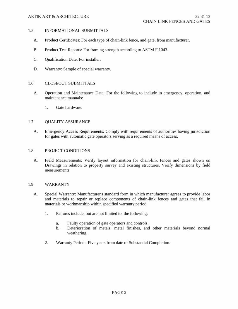
ARTIK ART & ARCHITECTURE 32 31 13 CHAIN LINK FENCES AND GATES
1.5 INFORMATIONAL SUBMITTALS
A. Product Certificates: For each type of chain-link fence, and gate, from manufacturer.
B. Product Test Reports: For framing strength according to ASTM F 1043.
C. Qualification Date: For installer.
D. Warranty: Sample of special warranty.
1.6 CLOSEOUT SUBMITTALS
A. Operation and Maintenance Data: For the following to include in emergency, operation, and maintenance manuals:
1. Gate hardware.
1.7 QUALITY ASSURANCE
A. Emergency Access Requirements: Comply with requirements of authorities having jurisdiction for gates with automatic gate operators serving as a required means of access.
1.8 PROJECT CONDITIONS
A. Field Measurements: Verify layout information for chain-link fences and gates shown on Drawings in relation to property survey and existing structures. Verify dimensions by field measurements.
1.9 WARRANTY
A. Special Warranty: Manufacturer's standard form in which manufacturer agrees to provide labor and materials to repair or replace components of chain-link fences and gates that fail in materials or workmanship within specified warranty period.
1. Failures include, but are not limited to, the following:
a. Faulty operation of gate operators and controls. b. Deterioration of metals, metal finishes, and other materials beyond normal
weathering.
2. Warranty Period: Five years from date of Substantial Completion.
PAGE 2
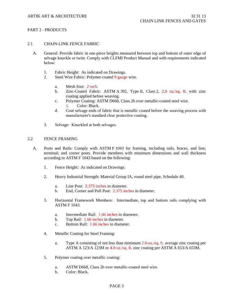
ARTIK ART & ARCHITECTURE 32 31 13 CHAIN LINK FENCES AND GATES
PART 2 - PRODUCTS
2.1 CHAIN-LINK FENCE FABRIC
A. General: Provide fabric in one-piece heights measured between top and bottom of outer edge of selvage knuckle or twist. Comply with CLFMI Product Manual and with requirements indicated below:
1. Fabric Height: As indicated on Drawings. 2. Steel Wire Fabric: Polymer-coated 9 gauge wire.
a. Mesh Size: 2 inch. b. Zinc-Coated Fabric: ASTM A 392, Type II, Class 2, 2.0 oz./sq. ft. with zinc
coating applied before weaving. c. Polymer Coating: ASTM D668, Class 2b over metallic-coated steel wire.
i. Color: Black. d. Coat selvage ends of fabric that is metallic coated before the weaving process with
manufacturer's standard clear protective coating.
3. Selvage: Knuckled at both selvages.
2.2 FENCE FRAMING
A. Posts and Rails: Comply with ASTM F 1043 for framing, including rails, braces, and line; terminal; and corner posts. Provide members with minimum dimensions and wall thickness according to ASTM F 1043 based on the following:
1. Fence Height: As indicated on Drawings.
2. Heavy Industrial Strength: Material Group IA, round steel pipe, Schedule 40.
a. Line Post: 2.375 inches in diameter. b. End, Corner and Pull Post: 2.375 inches in diameter.
3. Horizontal Framework Members: Intermediate, top and bottom rails complying with ASTM F 1043.
a. Intermediate Rail: 1.66 inches in diameter. b. Top Rail: 1.66 inches in diameter. c. Bottom Rail: 1.66 inches in diameter.
4. Metallic Coating for Steel Framing:
a. Type A consisting of not less than minimum 2.0-oz./sq. ft. average zinc coating per ASTM A 123/A 123M or 4.0-oz./sq. ft. zinc coating per ASTM A 653/A 653M.
5. Polymer coating over metallic coating: a. ASTM D668, Class 2b over metallic-coated steel wire. b. Color: Black.
PAGE 3

ARTIK ART & ARCHITECTURE 32 31 13 CHAIN LINK FENCES AND GATES
2.3 SWING GATES
A. General: Comply with ASTM F 900 for gate posts and single swing gate types.
1. Gate Leaf Width: As indicated. 2. Gate Fabric Height: As indicated.
B. Pipe and Tubing:
1. Galvanized Steel: Comply with ASTM F 1043 and ASTM F 1083; protective coating and finish to match fence framing.
2. Gate Posts: Round tubular steel. 3. Gate Frames and Bracing: Round tubular steel.
C. Frame Corner Construction: Welded.
D. Hardware:
1. Hinges: 180-degree outward swing. 2. Latches permitting operation from both sides of gate, with provision for padlocking
accessible from both sides of gate at non-egress gates. 3. Panic Device: Von Duprin 99 Series. 4. Kickplate: Provide smooth, uninterrupted surface over the gate on both sides. Extend
smooth surface for entire width of gate. Fabricate kickplate from 1/8 inch thick galvanized steel plate.
2.4 FITTINGS
A. General: Comply with ASTM F 626.
B. Post Caps: Provide for each post.
C. Rail and Brace Ends: Attach rails securely to each gate, corner, pull, and end post.
D. Rail Fittings: Provide the following:
1. Top Rail Sleeves: Pressed-steel or round-steel tubing not less than 6 inches long. 2. Rail Clamps: Line and corner boulevard clamps for connecting intermediate and bottom
rails in the fence line-to-line posts.
E. Tension Bars: Steel, length not less than 2 inches shorter than full height of chain-link fabric. Provide one bar for each gate and end post, and two for each corner and pull post, unless fabric is integrally woven into post.
F. Truss Rod Assemblies: Steel, hot-dip galvanized after threading rod and turnbuckle or other means of adjustment.
G. Tie Wires, Clips, and Fasteners: According to ASTM F 626.
1. Standard Round Wire Ties: For attaching chain-link fabric to posts, rails, and frames, complying with the following:
PAGE 4
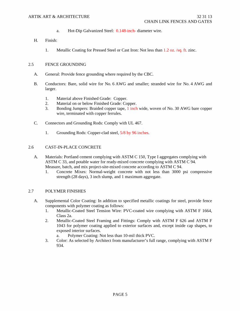
ARTIK ART & ARCHITECTURE 32 31 13 CHAIN LINK FENCES AND GATES
a. Hot-Dip Galvanized Steel: 0.148-inch- diameter wire.
H. Finish:
1. Metallic Coating for Pressed Steel or Cast Iron: Not less than 1.2 oz. /sq. ft. zinc.
2.5 FENCE GROUNDING
A. General: Provide fence grounding where required by the CBC.
B. Conductors: Bare, solid wire for No. 6 AWG and smaller; stranded wire for No. 4 AWG and larger.
1. Material above Finished Grade: Copper. 2. Material on or below Finished Grade: Copper. 3. Bonding Jumpers: Braided copper tape, 1 inch wide, woven of No. 30 AWG bare copper
wire, terminated with copper ferrules.
C. Connectors and Grounding Rods: Comply with UL 467.
1. Grounding Rods: Copper-clad steel, 5/8 by 96 inches.
2.6 CAST-IN-PLACE CONCRETE
A. Materials: Portland cement complying with ASTM C 150, Type I aggregates complying with ASTM C 33, and potable water for ready-mixed concrete complying with ASTM C 94. Measure, batch, and mix project-site-mixed concrete according to ASTM C 94. 1. Concrete Mixes: Normal-weight concrete with not less than 3000 psi compressive
strength (28 days), 3 inch slump, and 1 maximum aggregate.
2.7 POLYMER FINISHES
A. Supplemental Color Coating: In addition to specified metallic coatings for steel, provide fence components with polymer coating as follows: 1. Metallic-Coated Steel Tension Wire: PVC-coated wire complying with ASTM F 1664,
Class 2a. 2. Metallic-Coated Steel Framing and Fittings: Comply with ASTM F 626 and ASTM F
1043 for polymer coating applied to exterior surfaces and, except inside cap shapes, to exposed interior surfaces. a. Polymer Coating: Not less than 10-mil thick PVC.
3. Color: As selected by Architect from manufacturer’s full range, complying with ASTM F 934.
PAGE 5
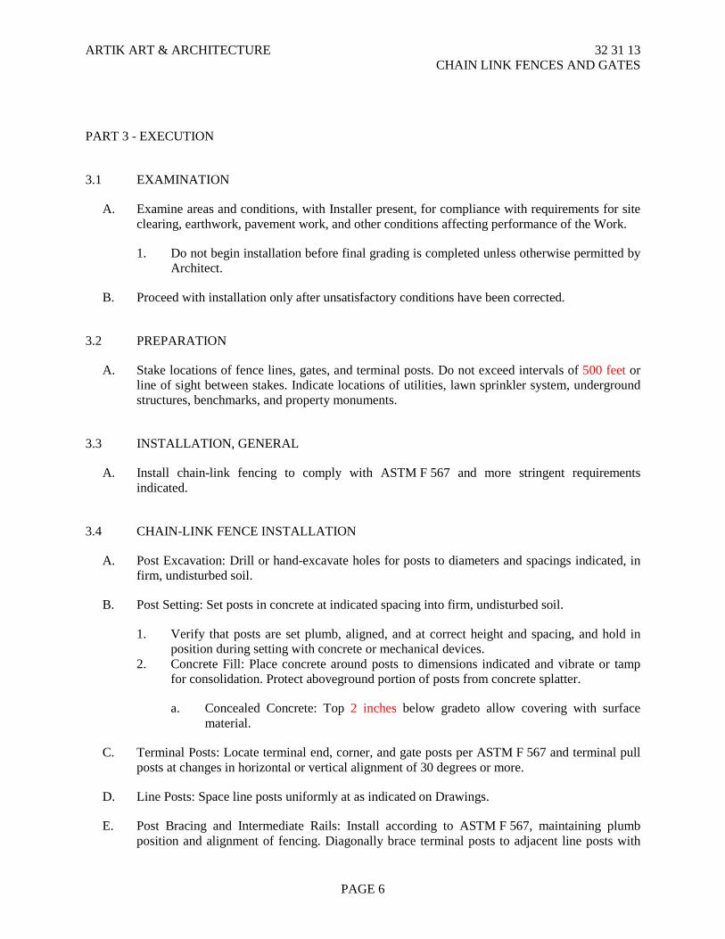
ARTIK ART & ARCHITECTURE 32 31 13 CHAIN LINK FENCES AND GATES
PART 3 - EXECUTION
3.1 EXAMINATION
A. Examine areas and conditions, with Installer present, for compliance with requirements for site clearing, earthwork, pavement work, and other conditions affecting performance of the Work.
1. Do not begin installation before final grading is completed unless otherwise permitted by Architect.
B. Proceed with installation only after unsatisfactory conditions have been corrected.
3.2 PREPARATION
A. Stake locations of fence lines, gates, and terminal posts. Do not exceed intervals of 500 feet or line of sight between stakes. Indicate locations of utilities, lawn sprinkler system, underground structures, benchmarks, and property monuments.
3.3 INSTALLATION, GENERAL
A. Install chain-link fencing to comply with ASTM F 567 and more stringent requirements indicated.
3.4 CHAIN-LINK FENCE INSTALLATION
A. Post Excavation: Drill or hand-excavate holes for posts to diameters and spacings indicated, in firm, undisturbed soil.
B. Post Setting: Set posts in concrete at indicated spacing into firm, undisturbed soil.
1. Verify that posts are set plumb, aligned, and at correct height and spacing, and hold in position during setting with concrete or mechanical devices.
2. Concrete Fill: Place concrete around posts to dimensions indicated and vibrate or tamp for consolidation. Protect aboveground portion of posts from concrete splatter.
a. Concealed Concrete: Top 2 inches below gradeto allow covering with surface material.
C. Terminal Posts: Locate terminal end, corner, and gate posts per ASTM F 567 and terminal pull posts at changes in horizontal or vertical alignment of 30 degrees or more.
D. Line Posts: Space line posts uniformly at as indicated on Drawings.
E. Post Bracing and Intermediate Rails: Install according to ASTM F 567, maintaining plumb position and alignment of fencing. Diagonally brace terminal posts to adjacent line posts with
PAGE 6
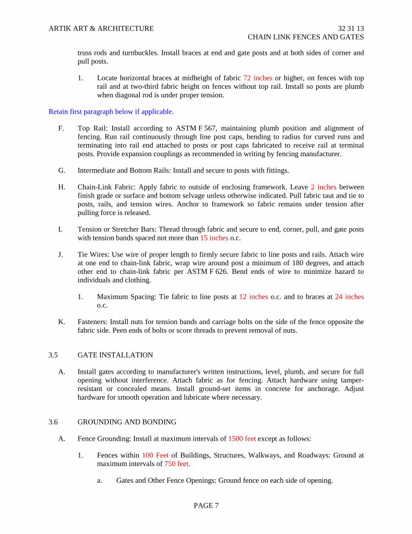
ARTIK ART & ARCHITECTURE 32 31 13 CHAIN LINK FENCES AND GATES
truss rods and turnbuckles. Install braces at end and gate posts and at both sides of corner and pull posts.
1. Locate horizontal braces at midheight of fabric 72 inches or higher, on fences with top rail and at two-third fabric height on fences without top rail. Install so posts are plumb when diagonal rod is under proper tension.
Retain first paragraph below if applicable.
F. Top Rail: Install according to ASTM F 567, maintaining plumb position and alignment of fencing. Run rail continuously through line post caps, bending to radius for curved runs and terminating into rail end attached to posts or post caps fabricated to receive rail at terminal posts. Provide expansion couplings as recommended in writing by fencing manufacturer.
G. Intermediate and Bottom Rails: Install and secure to posts with fittings.
H. Chain-Link Fabric: Apply fabric to outside of enclosing framework. Leave 2 inches between finish grade or surface and bottom selvage unless otherwise indicated. Pull fabric taut and tie to posts, rails, and tension wires. Anchor to framework so fabric remains under tension after pulling force is released.
I. Tension or Stretcher Bars: Thread through fabric and secure to end, corner, pull, and gate posts with tension bands spaced not more than 15 inches o.c.
J. Tie Wires: Use wire of proper length to firmly secure fabric to line posts and rails. Attach wire at one end to chain-link fabric, wrap wire around post a minimum of 180 degrees, and attach other end to chain-link fabric per ASTM F 626. Bend ends of wire to minimize hazard to individuals and clothing.
1. Maximum Spacing: Tie fabric to line posts at 12 inches o.c. and to braces at 24 inches o.c.
K. Fasteners: Install nuts for tension bands and carriage bolts on the side of the fence opposite the fabric side. Peen ends of bolts or score threads to prevent removal of nuts.
3.5 GATE INSTALLATION
A. Install gates according to manufacturer's written instructions, level, plumb, and secure for full opening without interference. Attach fabric as for fencing. Attach hardware using tamper-resistant or concealed means. Install ground-set items in concrete for anchorage. Adjust hardware for smooth operation and lubricate where necessary.
3.6 GROUNDING AND BONDING
A. Fence Grounding: Install at maximum intervals of 1500 feet except as follows:
1. Fences within 100 Feet of Buildings, Structures, Walkways, and Roadways: Ground at maximum intervals of 750 feet.
a. Gates and Other Fence Openings: Ground fence on each side of opening.
PAGE 7
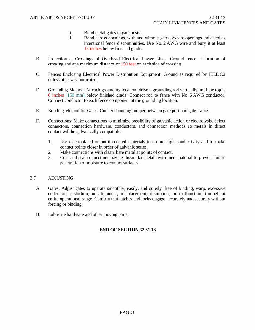
ARTIK ART & ARCHITECTURE 32 31 13 CHAIN LINK FENCES AND GATES
i. Bond metal gates to gate posts. ii. Bond across openings, with and without gates, except openings indicated as
intentional fence discontinuities. Use No. 2 AWG wire and bury it at least 18 inches below finished grade.
B. Protection at Crossings of Overhead Electrical Power Lines: Ground fence at location of crossing and at a maximum distance of 150 feet on each side of crossing.
C. Fences Enclosing Electrical Power Distribution Equipment: Ground as required by IEEE C2 unless otherwise indicated.
D. Grounding Method: At each grounding location, drive a grounding rod vertically until the top is 6 inches (150 mm) below finished grade. Connect rod to fence with No. 6 AWG conductor. Connect conductor to each fence component at the grounding location.
E. Bonding Method for Gates: Connect bonding jumper between gate post and gate frame.
F. Connections: Make connections to minimize possibility of galvanic action or electrolysis. Select connectors, connection hardware, conductors, and connection methods so metals in direct contact will be galvanically compatible.
1. Use electroplated or hot-tin-coated materials to ensure high conductivity and to make contact points closer in order of galvanic series.
2. Make connections with clean, bare metal at points of contact. 3. Coat and seal connections having dissimilar metals with inert material to prevent future
penetration of moisture to contact surfaces.
3.7 ADJUSTING
A. Gates: Adjust gates to operate smoothly, easily, and quietly, free of binding, warp, excessive deflection, distortion, nonalignment, misplacement, disruption, or malfunction, throughout entire operational range. Confirm that latches and locks engage accurately and securely without forcing or binding.
B. Lubricate hardware and other moving parts.
END OF SECTION 32 31 13
PAGE 8

ARTIK ART & ARCHITECTURE 32 31 19 ORNAMENTAL METAL FENCING AND GATES
SECTION 32 31 19
ORNAMENTAL METAL FENCING AND GATES
PART 1 - GENERAL
1.1 RELATED DOCUMENTS
A. Drawings and general provisions of the Contract, including General and Supplementary Conditions and Division 1 Specification Sections, apply to this Section.
1.2 SUMMARY
A. This Section includes pre-manufactured o r n a m e n t a l metal fencing and gate
systems, including concrete fence and gate post footings.
1.3 REFERENCES
A. ASTM International (American Society for Testing and Materials):
1. ASTM A 653: Specification for Steel Sheet, Zinc-Coated (Galvanized) or Zinc• Iron Alloy-Coated (Gal annealed) by the Hot-Dip Process.
2. ASTM A 924: Specification for General Requirements for Steel Sheet, Metallic• Coated by the Hot-Dip Process.
3. ASTM B 633: Specification for Electrodeposited Coatings of Zinc on Iron and Steel.
4. ASTM C 33: Specification for Concrete Aggregates.
5. ASTM C 94: Specification for Ready-Mixed Concrete. 6. ASTM C 150 Specification for Portland Cement. American Welding Society
(AWS). C. California Building Code (CBC) - California Code of Regulations, Title 24, Part 2.
D. National Association of Architectural Metal Manufacturers (NAAMM):
1. Metal Finishes Manual for Architectural and Metal Products.
1.4 PERFORMANCE REQUIREMENTS
A. Structural Performance: Provide ornamental metal fences and gates capable of withstanding the effects of gravity loads and the following loads and stresses within limits and under conditions indicated:
1. Minimum Post Size and Maximum Spacing for Wind Velocity Pressure:
Determine based on fence panel picket size and spacing, and on wind loads calculated based on requirements of the California Building Code using factors defined therein and applicable to local site conditions.
a. Wind Speed: 85 mph.
PAGE 1

ARTIK ART & ARCHITECTURE 32 31 19 ORNAMENTAL METAL FENCING AND GATES
2. Fence Panels (Typical Section Between Posts): Capable of supporting without deformation, a concentrated load of 500 LB/FT applied in the horizontal direction at mid-span between posts spaced at 8 feet apart.
3. Swing Gates: Capable of supporting a concentrated 200 LB/FT vertical load at the top corner strike side of the gate.
B. Thermal Movements: Provide ornamental metal fence and gate system that allows
for thermal movements resulting from the following maximum change (range) in ambient and surface temperatures by preventing buckling, opening of joints, overstressing of components, failure of connections, and other detrimental effects. Base engineering calculation on surface temperatures of materials due to both solar heat gain and nighttime-sky heat loss.
1. Temperature Change (Range): 120 degree F, ambient; 180 degree F, material surfaces.
1.5 SUBMITTALS
A. Product Data: Include construction details, material descriptions, dimensions
individual components and profiles, and finishes for ornamental metal fences gates.
1. Fence and gate posts, rails, pickets, and fittings. 2. Gates and hardware.
B. Shop Drawings: Show locations of fences, gates, posts, rails, pickets, details
extended posts, gate swings, hardware, and accessories. Indicate materials, dimensions sizes, weights, and finishes of components. Include plans, gate elevations, sections, details post anchorage, attachment, bracing and other required installation and operational clearances.
C. Samples for verification: For each type of ornamental metal fence and gate indicated.
D. Qualification Data: For Installer.
1.6 QUALITY ASSURANCE
A. installer Qualifications: An experienced installer who has completed ornamental metal fences and gates similar in material, design, and extent to those indicated this Project and whose work has resulted in construction with a record successful in-service performance.
PAGE 2
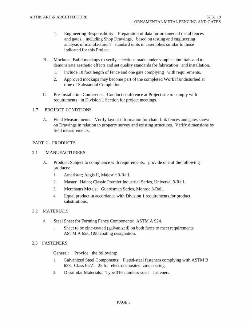
ARTIK ART & ARCHITECTURE 32 31 19 ORNAMENTAL METAL FENCING AND GATES
1. Engineering Responsibility: Preparation of data for ornamental metal fences and gates, including Shop Drawings, based on testing and engineering analysis of manufacturer's standard units in assemblies similar to those indicated for this Project.
B. Mockups: Build mockups to verify selections made under sample submittals and to
demonstrate aesthetic effects and set quality standards for fabrication and installation.
1. Include 10 foot length of fence and one gate complying with requirements.
2. Approved mockups may become part of the completed Work if undisturbed at time of Substantial Completion.
C. Pre-Installation Conference: Conduct conference at Project site to comply with
requirements in Division 1 Section for project meetings.
1.7 PROJECT CONDITIONS
A. Field Measurements: Verify layout information for chain-link fences and gates shown on Drawings in relation to property survey and existing structures. Verify dimensions by field measurements.
PART 2 - PRODUCTS
2.1 MANUFACTURERS
A. Product: Subject to compliance with requirements, provide one of the following products:
1. Ameristar; Aegis II, Majestic 3-Rail.
2. Master Halco; Classic Premier Industrial Series, Universal 3-Rail.
3. Merchants Metals; Guardsman Series, Monroe 3-Rail.
4. Equal product in accordance with Division 1 requirements for product substitutions.
2.2 MATERIALS
A. Steel Sheet for Forming Fence Components: ASTM A 924.
1. Sheet to be zinc-coated (galvanized) on both faces to meet requirements ASTM A 653, G90 coating designation.
2.3 FASTENERS
General: Provide the following:
1. Galvanized Steel Components: Plated-steel fasteners complying with ASTM B 633, Class Fe/Zn 25 for electrodeposited zinc coating.
2. Dissimilar Materials: Type 316 stainless-steel fasteners.
PAGE 3

ARTIK ART & ARCHITECTURE 32 31 19 ORNAMENTAL METAL FENCING AND GATES
B. Fasteners for Anchoring Ornamental Metal Fencing to Other Construction:
Select fasteners of type, grade, and class required to produce connections suitable for anchoring railings to other types of construction indicated, and capable of withstanding design loads.
C. Provide concealed fasteners for interconnecting fencing components and for
attaching fencing and gates to other work, unless otherwise indicated.
1. Where exposed fasteners are unavoidable, provide manufacturer’s tamper• resistant flat-head machine screws, unless otherwise indicated.
2.4 MISCELLANEOUS M A T E R I A L S
A. Seals for Picket/Rail Intersections: Manufacturer’s standard PVC grommets for
sealing top surface of horizontal rails where each vertical picket penetrates through rail.
1. Color: Match color of fencing components.
B. Decorative pattern along fence and gates:
1. 1 /8" thick steel spot welded to fence posts and pickets and gate vertical perimeter posts
C. Post Caps: Manufacturer’s formed metal caps for closing off exposed open end at
top of post. Finish and color to match post
1. Style: Flat top.
D. Welding Rods and Bare Electrodes: Select according to AWS specifications alloy welded.
E. Concrete: Normal-weight concrete with not less than 3000-psi compressive strength
(28 days), 3-inch slump. Measure, batch, and mix according to ASTM C 94.
1. Portland cement: ASTM C 150, Type I or II
2. Aggregate: ASTM C33; 1-inch maximum size.
3. Water: ASTM C 94; potable.
2.5 FABRICATION
a. General: Fabricate ornamental metal fencing to comply with requirements indicated for design, dimensions, member sizes and spacing, details, finish and anchorage, but not less than that required to support specified design loads.
1. Provide manufacturer’s standard system which includes the following features: a. Allows variable pitch at rail/post connections to accommodate different
ground slope conditions in the field. b. Pickets are connected to rails with concealed galvanized steel retaining
rod along length of rail, which passes through predrilled opening in each picket to lock picket into place or other means of connecting to allow variable between picket and rail to accommodate different ground slope conditions.
PAGE 4
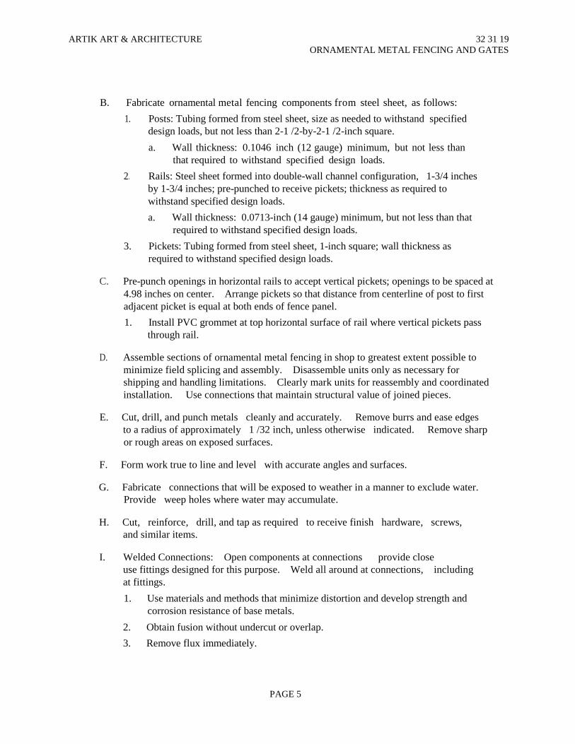
ARTIK ART & ARCHITECTURE 32 31 19 ORNAMENTAL METAL FENCING AND GATES
B. Fabricate ornamental metal fencing components from steel sheet, as follows:
1. Posts: Tubing formed from steel sheet, size as needed to withstand specified design loads, but not less than 2-1 /2-by-2-1 /2-inch square.
a. Wall thickness: 0.1046 inch (12 gauge) minimum, but not less than that required to withstand specified design loads.
2. Rails: Steel sheet formed into double-wall channel configuration, 1-3/4 inches by 1-3/4 inches; pre-punched to receive pickets; thickness as required to withstand specified design loads.
a. Wall thickness: 0.0713-inch (14 gauge) minimum, but not less than that required to withstand specified design loads.
3. Pickets: Tubing formed from steel sheet, 1-inch square; wall thickness as required to withstand specified design loads.
C. Pre-punch openings in horizontal rails to accept vertical pickets; openings to be spaced at
4.98 inches on center. Arrange pickets so that distance from centerline of post to first adjacent picket is equal at both ends of fence panel.
1. Install PVC grommet at top horizontal surface of rail where vertical pickets pass through rail.
D. Assemble sections of ornamental metal fencing in shop to greatest extent possible to
minimize field splicing and assembly. Disassemble units only as necessary for shipping and handling limitations. Clearly mark units for reassembly and coordinated installation. Use connections that maintain structural value of joined pieces.
E. Cut, drill, and punch metals cleanly and accurately. Remove burrs and ease edges
to a radius of approximately 1 /32 inch, unless otherwise indicated. Remove sharp or rough areas on exposed surfaces.
F. Form work true to line and level with accurate angles and surfaces.
G. Fabricate connections that will be exposed to weather in a manner to exclude water.
Provide weep holes where water may accumulate.
H. Cut, reinforce, drill, and tap as required to receive finish hardware, screws, and similar items.
I. Welded Connections: Open components at connections provide close
use fittings designed for this purpose. Weld all around at connections, including at fittings.
1. Use materials and methods that minimize distortion and develop strength and corrosion resistance of base metals.
2. Obtain fusion without undercut or overlap.
3. Remove flux immediately.
PAGE 5
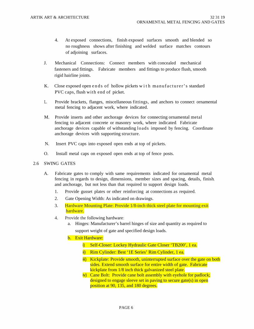
ARTIK ART & ARCHITECTURE 32 31 19 ORNAMENTAL METAL FENCING AND GATES
4. At exposed connections, finish exposed surfaces smooth and blended so
no roughness shows after finishing and welded surface matches contours of adjoining surfaces.
J. Mechanical Connections: Connect members with concealed mechanical
fasteners and fittings. Fabricate members and fittings to produce flush, smooth rigid hairline joints.
K. Close exposed open e n d s of hollow pickets w i t h ma nufac tu re r ’ s standard
PVC caps, flush with end of picket.
L. Provide brackets, flanges, miscellaneous fittings, and anchors to connect ornamental metal fencing to adjacent work, where indicated.
M. Provide inserts and other anchorage devices for connecting ornamental metal
fencing to adjacent concrete or masonry work, where indicated. Fabricate anchorage devices capable of withstanding loads imposed by fencing. Coordinate anchorage devices with supporting structure.
N. Insert PVC caps into exposed open ends at top of pickets.
O. Install metal caps on exposed open ends at top of fence posts.
2.6 SWING GATES
A. Fabricate gates to comply with same requirements indicated for ornamental metal
fencing in regards to design, dimensions, member sizes and spacing, details, finish, and anchorage, but not less than that required to support design loads.
1. Provide gusset plates or other reinforcing at connections as required.
2. Gate Opening Width: As indicated on drawings.
3. Hardware Mounting Plate: Provide 1/8-inch thick steel plate for mounting exit hardware.
4. Provide the following hardware:: a. Hinges: Manufacturer’s barrel hinges of size and quantity as required to
support weight of gate and specified design loads.
b. Exit Hardware:
i) Self-Closer: Lockey Hydraulic Gate Closer ‘TB200’, 1 ea.
ii) Rim Cylinder: Best ‘1E Series’ Rim Cylinder, 1 ea.
iii) Kickplate: Provide smooth, uninterrupted surface over the gate on both sides. Extend smooth surface for entire width of gate. Fabricate kickplate from 1/8 inch thick galvanized steel plate.
iv) Cane Bolt: Provide cane bolt assembly with eyehole for padlock; designed to engage sleeve set in paving to secure gate(s) in open position at 90, 135, and 180 degrees.
PAGE 6

ARTIK ART & ARCHITECTURE 32 31 19 ORNAMENTAL METAL FENCING AND GATES
2. 7 FINISHES
A. General: Comply with NAAMM's "Metal Finishes Manual for Architectural and Metal Products" for recommendations for applying and designating finishes.
B. Powder-Coat Finish: Prepare, treat, and coat galvanized metal to comply with
coating manufacturer’s written instructions and as follows:
1. Process:
a. Prepare galvanized metal by thoroughly removing grease, dirt, oil, flux, and other foreign matter.
b. Treat prepared metal with zinc-phosphate pretreatment, rinse, and seal surfaces.
c. Electrostatically spray-apply thermosetting epoxy powder coating base coat with a cured-film thickness not less than 2.0 mils.
d. Electrostatically spray-apply thermosetting polyester powder coating topcoat with cured-film thickness not less than 2.0 mils.
2. Salt and Spray Performance: No deterioration, loss of adhesion, or other effects after 3,500 hours of exposure, per ASTM B 117.
3. Color: Black.
PART 3 - EXECUTION
3.1 EXAMINATION
A. Examine areas and conditions, with Installer present, for compliance with requirements for site clearing, earthwork, paving work, and other conditions affecting performance.
B. Do not begin installation before final grading is completed, unless otherwise
permitted by Architect.
C. Proceed with installation only after unsatisfactory conditions have been corrected.
3.2 PREPARATION
A. Stake locations of fence lines, gates, and end and corner posts. Do not exceed intervals of 500 feet or line of sight between stakes. Indicate locations utilities, lawn sprinkler system, underground structures, benchmarks, and property monuments.
3.3 ORNAMENTAL METAL FENCING INSTALLATION
A. General: Install ornamental metal fencing system in accordance with written
instructions of manufacturer. B. Where occurring along property line, install fencing on established boundary lines
inside property line.
PAGE 7
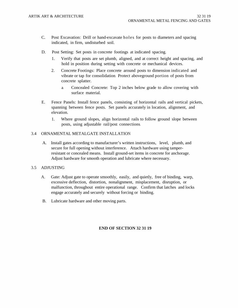
ARTIK ART & ARCHITECTURE 32 31 19 ORNAMENTAL METAL FENCING AND GATES
C. Post Excavation: Drill or hand-excavate holes for posts to diameters and spacing
indicated, in firm, undisturbed soil.
D. Post Setting: Set posts in concrete footings at indicated spacing.
1. Verify that posts are set plumb, aligned, and at correct height and spacing, and hold in position during setting with concrete or mechanical devices.
2. Concrete Footings: Place concrete around posts to dimension indicated and vibrate or tap for consolidation. Protect aboveground portion of posts from concrete splatter.
a. Concealed Concrete: Top 2 inches below grade to allow covering with surface material.
E. Fence Panels: Install fence panels, consisting of horizontal rails and vertical pickets,
spanning between fence posts. Set panels accurately in location, alignment, and elevation.
1. Where ground slopes, align horizontal rails to follow ground slope between posts, using adjustable rail/post connections.
3.4 ORNAMENTAL METALGATE INSTALLATION
A. Install gates according to manufacturer’s written instructions, level, plumb, and
secure for full opening without interference. Attach hardware using tamper-resistant or concealed means. Install ground-set items in concrete for anchorage. Adjust hardware for smooth operation and lubricate where necessary.
3.5 ADJUSTING
A. Gate: Adjust gate to operate smoothly, easily, and quietly, free of binding, warp,
excessive deflection, distortion, nonalignment, misplacement, disruption, or malfunction, throughout entire operational range. Confirm that latches and locks engage accurately and securely without forcing or binding.
B. Lubricate hardware and other moving parts.
END OF SECTION 32 31 19
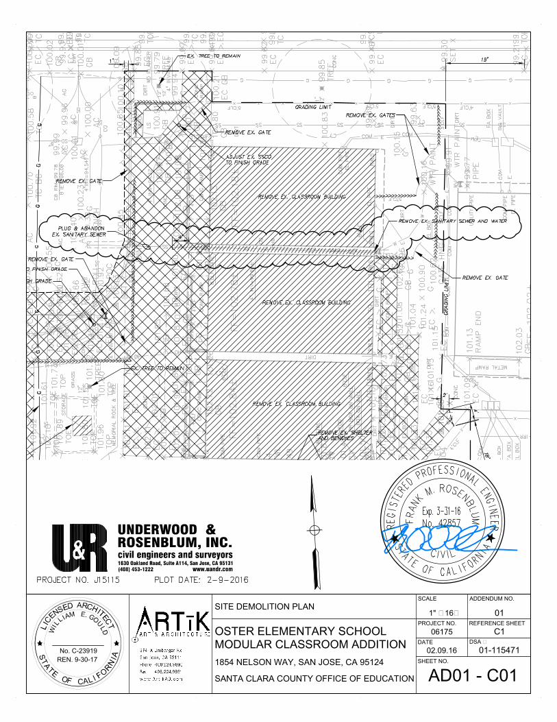
OSTER ELEMENTARY SCHOOL
SANTA CLARA COUNTY OFFICE OF EDUCATION
MODULAR CLASSROOM ADDITION
No. C-23919
REN. 9-30-17
1854 NELSON WAY, SAN JOSE, CA 95124
ADDENDUM NO.
SHEET NO.
REFERENCE SHEET
SCALE
06175
DATE
PROJECT NO.
DSA #
01-11547102.09.16
011" = 16'
C1
AD01 - C01
SITE DEMOLITION PLAN
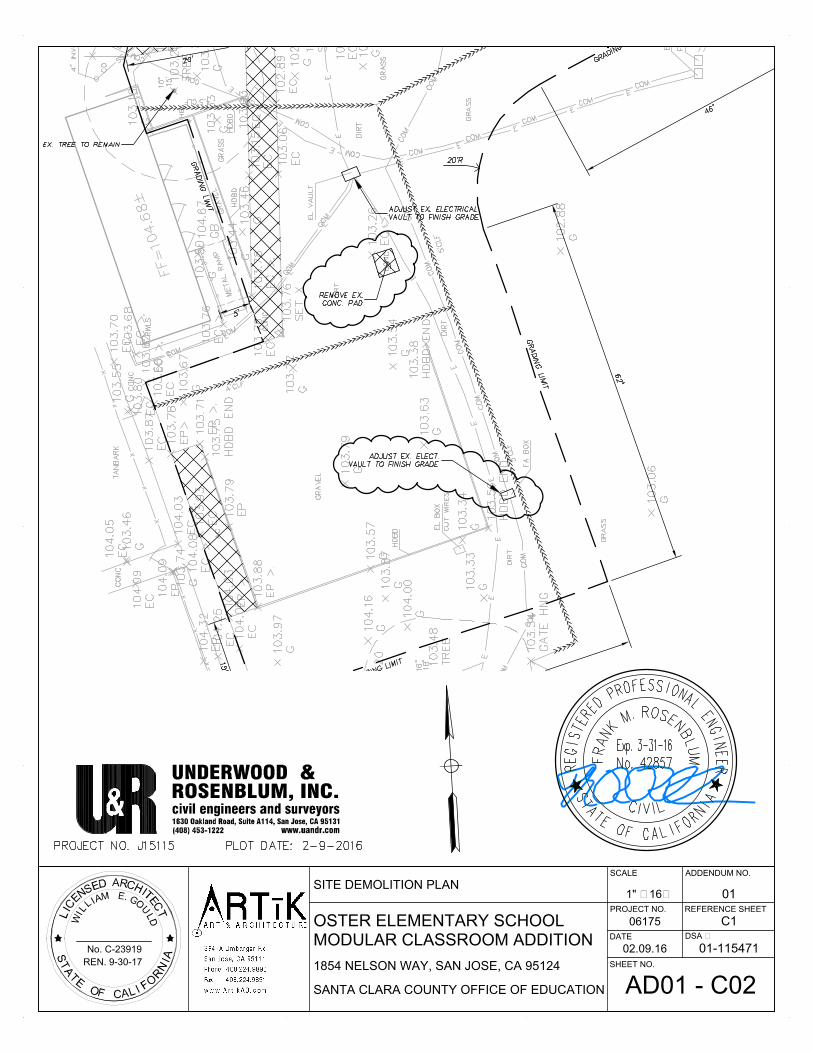
OSTER ELEMENTARY SCHOOL
SANTA CLARA COUNTY OFFICE OF EDUCATION
MODULAR CLASSROOM ADDITION
No. C-23919
REN. 9-30-17
1854 NELSON WAY, SAN JOSE, CA 95124
ADDENDUM NO.
SHEET NO.
REFERENCE SHEET
SCALE
06175
DATE
PROJECT NO.
DSA #
01-11547102.09.16
011" = 16'
C1
AD01 - C02
SITE DEMOLITION PLAN

(E) BUILDING 9
DSA #01-110896
OSTER ELEMENTARY SCHOOL
SANTA CLARA COUNTY OFFICE OF EDUCATION
MODULAR CLASSROOM ADDITION
No. C-23919
REN. 9-30-17
1854 NELSON WAY, SAN JOSE, CA 95124
ADDENDUM NO.
SHEET NO.
REFERENCE SHEET
SCALE
06175
DATE
PROJECT NO.
DSA #
01-11547102.09.16
011" = 16"
C2
AD01 - C03
SITE GRADING & PAVING PLAN

OSTER ELEMENTARY SCHOOL
SANTA CLARA COUNTY OFFICE OF EDUCATION
MODULAR CLASSROOM ADDITION
No. C-23919
REN. 9-30-17
1854 NELSON WAY, SAN JOSE, CA 95124
ADDENDUM NO.
SHEET NO.
REFERENCE SHEET
SCALE
06175
DATE
PROJECT NO.
DSA #
01-11547102.09.16
011" = 16"
C2
AD01 - C04
SITE GRADING & PAVING PLAN
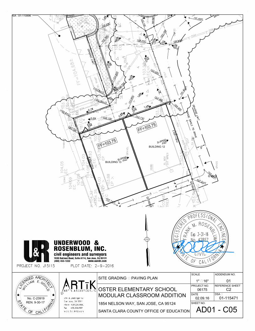
BUILDING 13
BUILDING 12
DSA #01-110896
OSTER ELEMENTARY SCHOOL
SANTA CLARA COUNTY OFFICE OF EDUCATION
MODULAR CLASSROOM ADDITION
No. C-23919
REN. 9-30-17
1854 NELSON WAY, SAN JOSE, CA 95124
ADDENDUM NO.
SHEET NO.
REFERENCE SHEET
SCALE
06175
DATE
PROJECT NO.
DSA #
01-11547102.09.16
011" = 16"
C2
AD01 - C05
SITE GRADING & PAVING PLAN

OSTER ELEMENTARY SCHOOL
SANTA CLARA COUNTY OFFICE OF EDUCATION
MODULAR CLASSROOM ADDITION
No. C-23919
REN. 9-30-17
1854 NELSON WAY, SAN JOSE, CA 95124
ADDENDUM NO.
SHEET NO.
REFERENCE SHEET
SCALE
06175
DATE
PROJECT NO.
DSA #
01-11547102.09.16
011" = 16"
C3
AD01 - C06
SITE PLUMBING PLAN
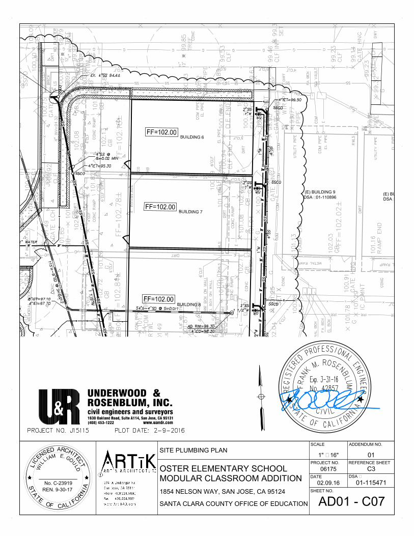
(E) BUILDING 10
DSA #01-110896
(E) BUILDING 9
DSA #01-110896
OSTER ELEMENTARY SCHOOL
SANTA CLARA COUNTY OFFICE OF EDUCATION
MODULAR CLASSROOM ADDITION
No. C-23919
REN. 9-30-17
1854 NELSON WAY, SAN JOSE, CA 95124
ADDENDUM NO.
SHEET NO.
REFERENCE SHEET
SCALE
06175
DATE
PROJECT NO.
DSA #
01-11547102.09.16
011" = 16"
C3
AD01 - C07
SITE PLUMBING PLAN
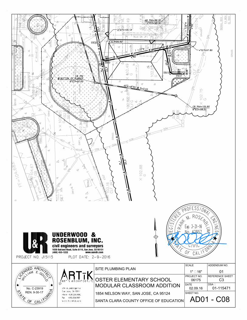
OSTER ELEMENTARY SCHOOL
SANTA CLARA COUNTY OFFICE OF EDUCATION
MODULAR CLASSROOM ADDITION
No. C-23919
REN. 9-30-17
1854 NELSON WAY, SAN JOSE, CA 95124
ADDENDUM NO.
SHEET NO.
REFERENCE SHEET
SCALE
06175
DATE
PROJECT NO.
DSA #
01-11547102.09.16
011" = 16"
C3
AD01 - C08
SITE PLUMBING PLAN

BUILDING 13
BUILDING 12
OSTER ELEMENTARY SCHOOL
SANTA CLARA COUNTY OFFICE OF EDUCATION
MODULAR CLASSROOM ADDITION
No. C-23919
REN. 9-30-17
1854 NELSON WAY, SAN JOSE, CA 95124
ADDENDUM NO.
SHEET NO.
REFERENCE SHEET
SCALE
06175
DATE
PROJECT NO.
DSA #
01-11547102.09.16
011" = 16"
C3
AD01 - C09
SITE PLUMBING PLAN

OSTER ELEMENTARY SCHOOL
SANTA CLARA COUNTY OFFICE OF EDUCATION
MODULAR CLASSROOM ADDITION
No. C-23919
REN. 9-30-17
1854 NELSON WAY, SAN JOSE, CA 95124
ADDENDUM NO.
SHEET NO.
REFERENCE SHEET
SCALE
06175
DATE
PROJECT NO.
DSA #
01-11547102.09.16
01NTS
C3
AD01 - C10
SITE PLUMBING PLAN
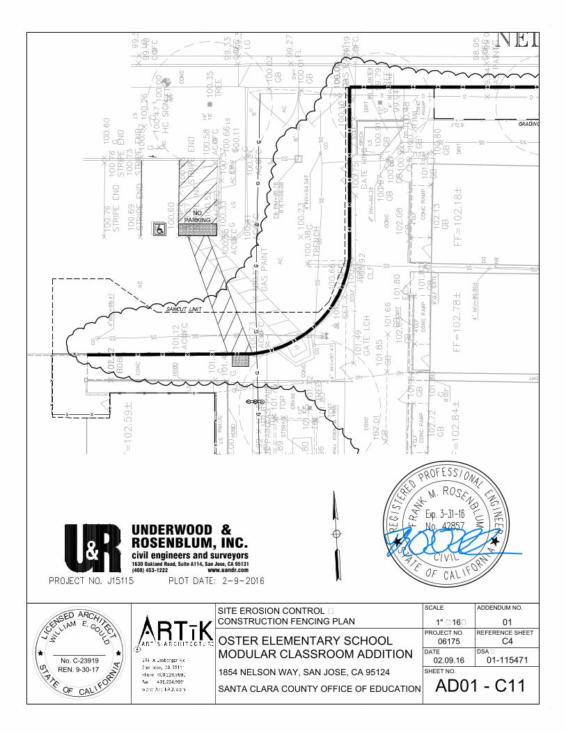
OSTER ELEMENTARY SCHOOL
SANTA CLARA COUNTY OFFICE OF EDUCATION
MODULAR CLASSROOM ADDITION
No. C-23919
REN. 9-30-17
1854 NELSON WAY, SAN JOSE, CA 95124
ADDENDUM NO.
SHEET NO.
REFERENCE SHEET
SCALE
06175
DATE
PROJECT NO.
DSA #
01-11547102.09.16
011" = 16'
C4
AD01 - C11
SITE EROSION CONTROL &
CONSTRUCTION FENCING PLAN
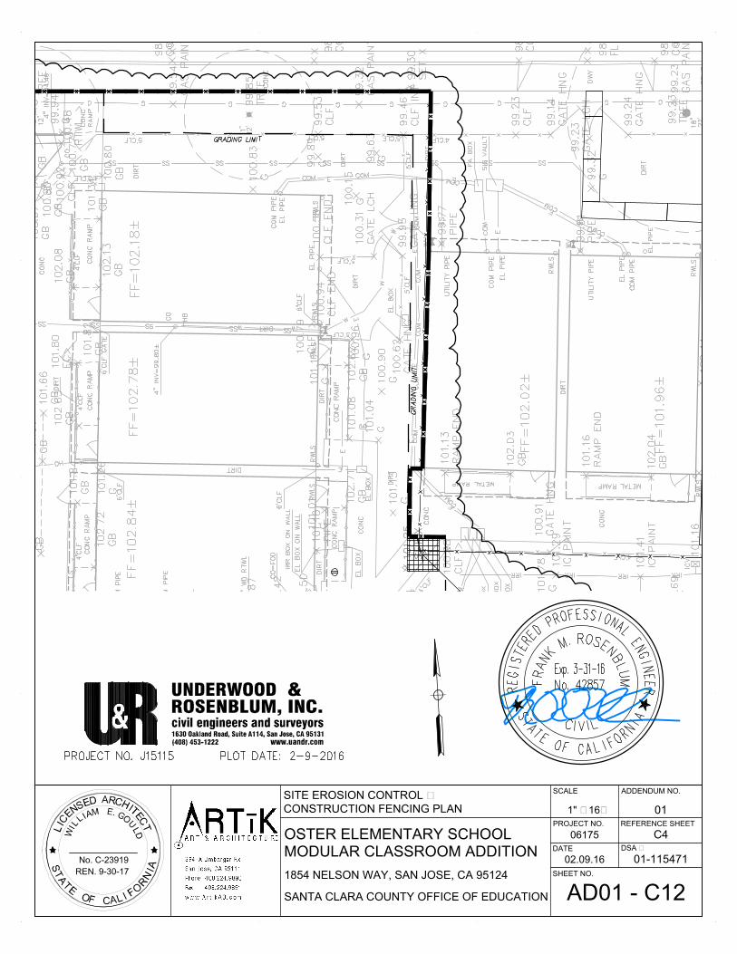
OSTER ELEMENTARY SCHOOL
SANTA CLARA COUNTY OFFICE OF EDUCATION
MODULAR CLASSROOM ADDITION
No. C-23919
REN. 9-30-17
1854 NELSON WAY, SAN JOSE, CA 95124
ADDENDUM NO.
SHEET NO.
REFERENCE SHEET
SCALE
06175
DATE
PROJECT NO.
DSA #
01-11547102.09.16
011" = 16'
C4
AD01 - C12
SITE EROSION CONTROL &
CONSTRUCTION FENCING PLAN
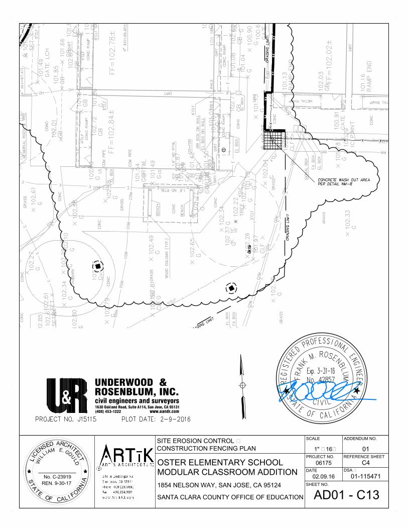
OSTER ELEMENTARY SCHOOL
SANTA CLARA COUNTY OFFICE OF EDUCATION
MODULAR CLASSROOM ADDITION
No. C-23919
REN. 9-30-17
1854 NELSON WAY, SAN JOSE, CA 95124
ADDENDUM NO.
SHEET NO.
REFERENCE SHEET
SCALE
06175
DATE
PROJECT NO.
DSA #
01-11547102.09.16
011" = 16'
C4
AD01 - C13
SITE EROSION CONTROL &
CONSTRUCTION FENCING PLAN

OSTER ELEMENTARY SCHOOL
SANTA CLARA COUNTY OFFICE OF EDUCATION
MODULAR CLASSROOM ADDITION
No. C-23919
REN. 9-30-17
1854 NELSON WAY, SAN JOSE, CA 95124
ADDENDUM NO.
SHEET NO.
REFERENCE SHEET
SCALE
06175
DATE
PROJECT NO.
DSA #
01-11547102.09.16
011" = 16'
C4
AD01 - C14
SITE EROSION CONTROL &
CONSTRUCTION FENCING PLAN

OSTER ELEMENTARY SCHOOL
SANTA CLARA COUNTY OFFICE OF EDUCATION
MODULAR CLASSROOM ADDITION
No. C-23919
REN. 9-30-17
1854 NELSON WAY, SAN JOSE, CA 95124
ADDENDUM NO.
SHEET NO.
REFERENCE SHEET
SCALE
06175
DATE
PROJECT NO.
DSA #
01-11547102.09.16
011" = 70'
C4
AD01 - C15
SITE EROSION CONTROL &
CONSTRUCTION FENCING PLAN

X
X
X
X
X
X
X
X
XX
XX
XX
XX
XX
XX
XX
(E) BUILDING 5
DSA #61073
(E) PARKING LOT A
TYP.
TYP.
TYP.
TYP.
TYP.
TYP.
TYP.
01
01
01
04
04
05
05
09
10
01
10
01
01
01
OSTER ELEMENTARY SCHOOL
SANTA CLARA COUNTY OFFICE OF EDUCATION
MODULAR CLASSROOM ADDITION
No. C-23919
REN. 9-30-17
1854 NELSON WAY, SAN JOSE, CA 95124
ADDENDUM NO.
SHEET NO.
REFERENCE SHEET
SCALE
06175
DATE
PROJECT NO.
DSA #
01-115471
ENLARGED DEMOLITION
3/32" = 1'-0"
AD01-A1
1/A1.03
SITE PLAN 01
02.08.16

BUILDING
#01-110896
(E) BUILDING 6
DSA #59484
(E) BUILDING 7
DSA #59484
X
X
X
X
X
X
X
XX
XX
X
XX
X
X
X
X
X
X
X
X
X
X
X
X
X
X
X
X
X
XX
X
X
X
X
X
X
X
X
X
X
XX
XX
X
X
XXXXXXXXXXXXXXXXX
XXX
X
XXX
X
X
XX
XX
XX
X
XX
X
X
XX
TYP.
TYP.
TYP.
TYP.
TYP.
01
01
01
02
02
03
04
01
01
OSTER ELEMENTARY SCHOOL
SANTA CLARA COUNTY OFFICE OF EDUCATION
MODULAR CLASSROOM ADDITION
No. C-23919
REN. 9-30-17
1854 NELSON WAY, SAN JOSE, CA 95124
ADDENDUM NO.
SHEET NO.
REFERENCE SHEET
SCALE
06175
DATE
PROJECT NO.
DSA #
01-115471
ENLARGED DEMOLITION
3/32" = 1'-0"
AD01-A2
1/A1.03
SITE PLAN 01
02.08.16

TYP.
(E)
BUILDING
10
DSA
#01-110896
(E)
BUILDING
9
DSA
#01-110896
X
X
X
TYP.
TYP.
TYP.
TYP.
12
12
01
04
11
11
01
01
01
OSTER ELEMENTARY SCHOOL
SANTA CLARA COUNTY OFFICE OF EDUCATION
MODULAR CLASSROOM ADDITION
No. C-23919
REN. 9-30-17
1854 NELSON WAY, SAN JOSE, CA 95124
ADDENDUM NO.
SHEET NO.
REFERENCE SHEET
SCALE
06175
DATE
PROJECT NO.
DSA #
01-115471
ENLARGED DEMOLITION
3/32" = 1'-0"
AD01-A3
1/A1.03
SITE PLAN 01
02.08.16
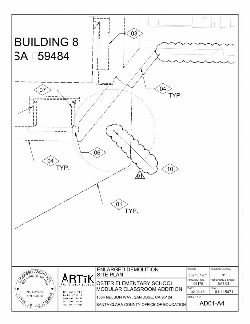
(E) BUILDING 8
DSA #59484
X
X
X
X
X
X
X
X
X
X
X
X
X
X
X
X
X
X
X
X
X
X
X
X
X
X
X
X
X
X
X
X
X
X
X
X
X
X
X
X
X
X
X
X
X
TYP.
TYP.
TYP.
01
03
04
04
06
07
10
01
OSTER ELEMENTARY SCHOOL
SANTA CLARA COUNTY OFFICE OF EDUCATION
MODULAR CLASSROOM ADDITION
No. C-23919
REN. 9-30-17
1854 NELSON WAY, SAN JOSE, CA 95124
ADDENDUM NO.
SHEET NO.
REFERENCE SHEET
SCALE
06175
DATE
PROJECT NO.
DSA #
01-115471
ENLARGED DEMOLITION
3/32" = 1'-0"
AD01-A4
1/A1.03
SITE PLAN 01
02.08.16
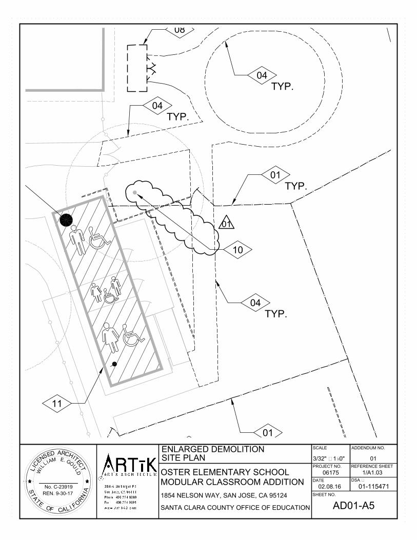
X
X
X
X
X
X
X
X
X
X
X
X
X
X
X
X
X
X
X
X
X
X
X
X
X
X
X
X
X
X
X
X
X
X
X
X
X
X
X
X
X
X
X
X
X
X
X
X
X
X
X
XX
XX
XX
X
X
X
X
X
X
X
X
X
X
X
X
X
X
X
X
X
X
X
TYP.
TYP.
TYP.
TYP.
11
01
01
04
04
04
08
10
01
OSTER ELEMENTARY SCHOOL
SANTA CLARA COUNTY OFFICE OF EDUCATION
MODULAR CLASSROOM ADDITION
No. C-23919
REN. 9-30-17
1854 NELSON WAY, SAN JOSE, CA 95124
ADDENDUM NO.
SHEET NO.
REFERENCE SHEET
SCALE
06175
DATE
PROJECT NO.
DSA #
01-115471
ENLARGED DEMOLITION
3/32" = 1'-0"
AD01-A5
1/A1.03
SITE PLAN 01
02.08.16

OSTER ELEMENTARY SCHOOL
SANTA CLARA COUNTY OFFICE OF EDUCATION
MODULAR CLASSROOM ADDITION
No. C-23919
REN. 9-30-17
1854 NELSON WAY, SAN JOSE, CA 95124
ADDENDUM NO.
SHEET NO.
REFERENCE SHEET
SCALE
06175
DATE
PROJECT NO.
DSA #
01-115471
ENLARGED DEMOLITION
-
AD01-A6
A1.03
SITE PLAN - KEYNOTES 01
02.08.16
KEYNOTES
DEMOLISH (E) CONCRETE RAMP AND METAL HANDRAILS.
DEMOLISH (E) CONCRETE.
DEMOLISH (E) WOOD TRELLIS IN IT'S ENTIRETY.
DEMOLISH (E) WOOD BENCH IN IT'S ENTIRETY.
DEMOLISH (E) CHAINLINK FENCING.
DEMOLISH (E) WOOD HEADERBOARD.
DEMOLISH (E) MODULAR BUILDING. DISCONNECT UTILITIES, REFER TO CIVIL
AND ELECTRICAL DRAWINGS FOR ADDITIONAL INFORMATION.
REMOVE AND SALVAGE (E) STORAGE SHED.
(E) TREE TO REMAIN.
(E) MODULAR BUILDING TO REMAIN.
REMOVE (E) PARKING STRIPING.
01
02
03
04
05
06
07
08
09
10
11
01
(E) CHAINLINK FENCING TO REMAIN.12
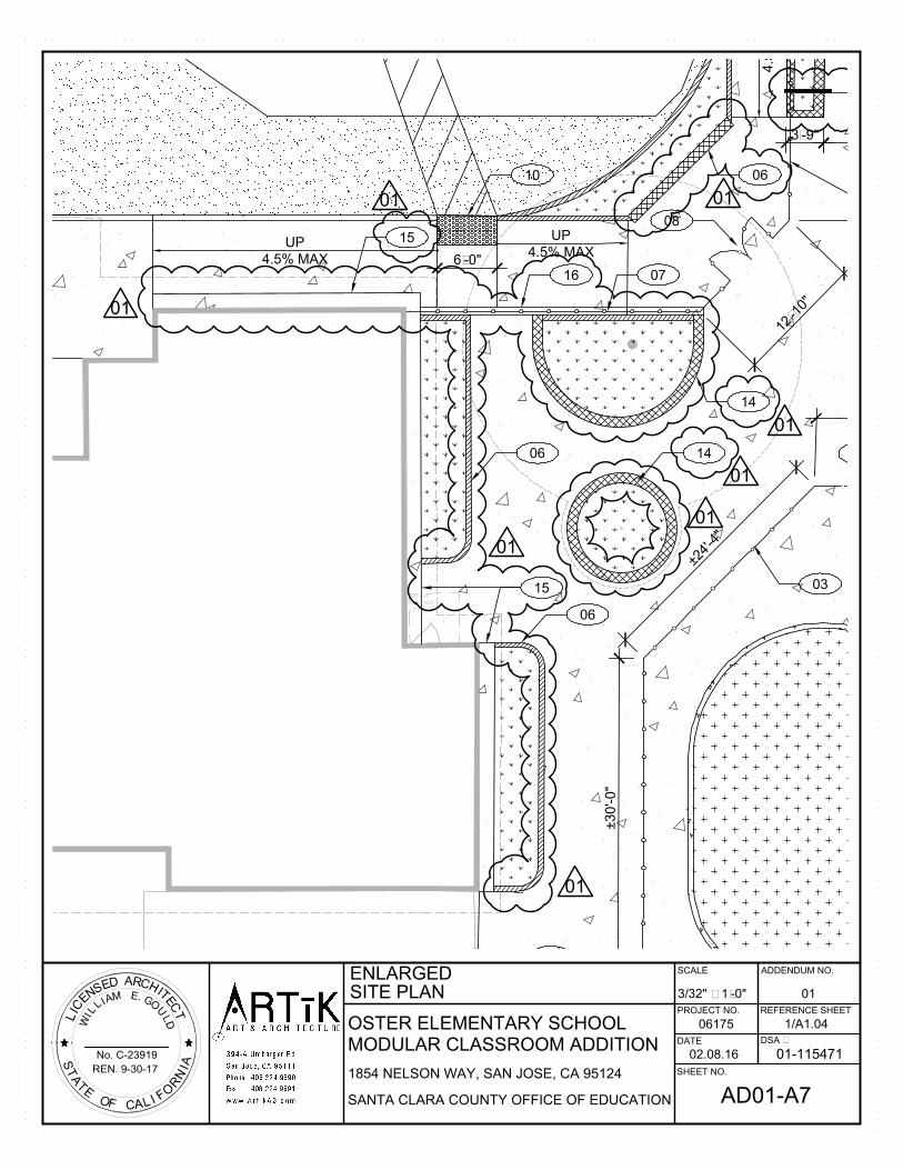
UP
4.5% MAX
3'-9"
±
2
4
'
-
4
"
±30'-0"
UP
4.5% MAX
4.5
% M
AX
1
2
'
-
1
0
"
6'-0"
60" x 60"
CLR. AND
LEVEL
03
14
14
06
06
06
15
08
07
10
16
15
01
01
01
01
01
01
01
12
01
OSTER ELEMENTARY SCHOOL
SANTA CLARA COUNTY OFFICE OF EDUCATION
MODULAR CLASSROOM ADDITION
No. C-23919
REN. 9-30-17
1854 NELSON WAY, SAN JOSE, CA 95124
ADDENDUM NO.
SHEET NO.
REFERENCE SHEET
SCALE
06175
DATE
PROJECT NO.
DSA #
01-115471
ENLARGED
3/32" = 1'-0"
AD01-A7
1/A1.04
SITE PLAN 01
02.08.16
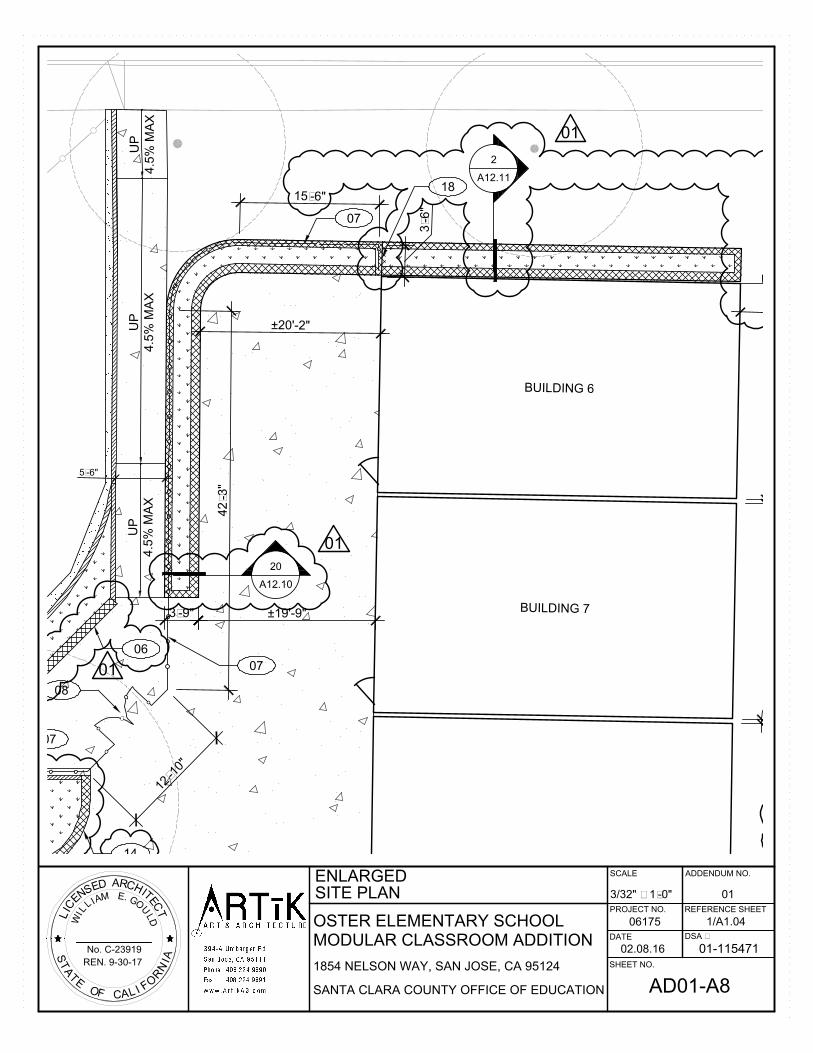
5'-6"
3'-9" ±19'-9"
BUILDING 6
BUILDING 7
±20'-2"
3'-6"
UP
4.5%
M
AX
UP
4.5
% M
AX
UP
4.5
% M
AX
1
2
'
-
1
0
"
15'-6"
42'-3"
20
A12.10
2
A12.11
14
06
08
07
07
07
18
01
01
01
OSTER ELEMENTARY SCHOOL
SANTA CLARA COUNTY OFFICE OF EDUCATION
MODULAR CLASSROOM ADDITION
No. C-23919
REN. 9-30-17
1854 NELSON WAY, SAN JOSE, CA 95124
ADDENDUM NO.
SHEET NO.
REFERENCE SHEET
SCALE
06175
DATE
PROJECT NO.
DSA #
01-115471
ENLARGED
3/32" = 1'-0"
AD01-A8
1/A1.04
SITE PLAN 01
02.08.16
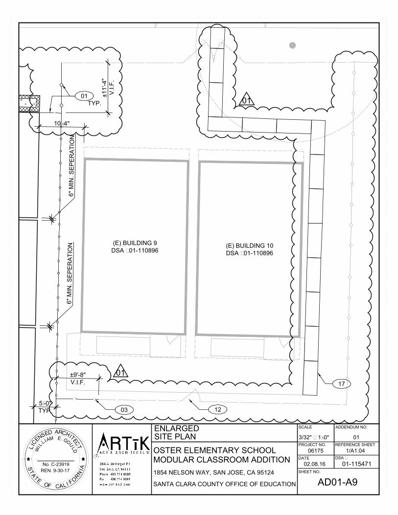
6" M
IN
. S
EP
ER
AT
IO
N
6" M
IN
. S
EP
ER
AT
IO
N
(E) BUILDING 10
DSA #01-110896
(E) BUILDING 9
DSA #01-110896
5'-0"
TYP.
10'-4"
±9'-8"
V.I.F.
±11'-4"
V.I.F
.
01
TYP.
0312
17
01
01
OSTER ELEMENTARY SCHOOL
SANTA CLARA COUNTY OFFICE OF EDUCATION
MODULAR CLASSROOM ADDITION
No. C-23919
REN. 9-30-17
1854 NELSON WAY, SAN JOSE, CA 95124
ADDENDUM NO.
SHEET NO.
REFERENCE SHEET
SCALE
06175
DATE
PROJECT NO.
DSA #
01-115471
ENLARGED
3/32" = 1'-0"
AD01-A9
1/A1.04
SITE PLAN 01
02.08.16
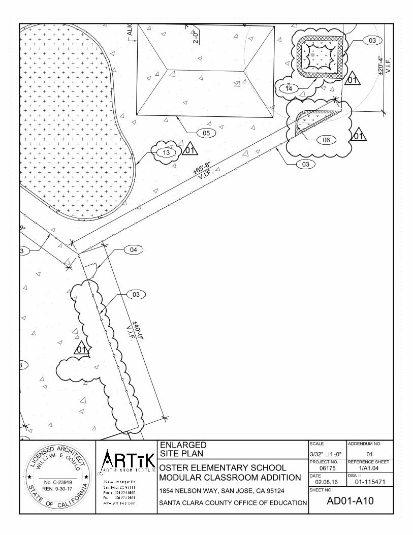
±
2
9
'
-
9
"
2'-0"
ALIG
N
±20'-4"
V.I.F
.
±
6
5
'
-
8
"
V
.
I
.
F
.
±
4
0
'-
0
"
V
.
I
.
F
.
03
03
03
03
03
04
05
13
14
01
01
01
01
06
11
OSTER ELEMENTARY SCHOOL
SANTA CLARA COUNTY OFFICE OF EDUCATION
MODULAR CLASSROOM ADDITION
No. C-23919
REN. 9-30-17
1854 NELSON WAY, SAN JOSE, CA 95124
ADDENDUM NO.
SHEET NO.
REFERENCE SHEET
SCALE
06175
DATE
PROJECT NO.
DSA #
01-115471
ENLARGED
3/32" = 1'-0"
AD01-A10
1/A1.04
SITE PLAN 01
02.08.16
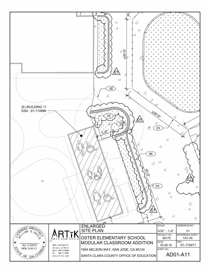
±
1
5
'-
0
"
±30'-0"
±
2
9
'
-
9
"
(E) BUILDING 11
DSA #01-110896
7
'-
0
"
4
0
'-
0
"
03
03
03
06
15
01
01
01
01
11
12
OSTER ELEMENTARY SCHOOL
SANTA CLARA COUNTY OFFICE OF EDUCATION
MODULAR CLASSROOM ADDITION
No. C-23919
REN. 9-30-17
1854 NELSON WAY, SAN JOSE, CA 95124
ADDENDUM NO.
SHEET NO.
REFERENCE SHEET
SCALE
06175
DATE
PROJECT NO.
DSA #
01-115471
ENLARGED
3/32" = 1'-0"
AD01-A11
1/A1.04
SITE PLAN 01
02.08.16

OSTER ELEMENTARY SCHOOL
SANTA CLARA COUNTY OFFICE OF EDUCATION
MODULAR CLASSROOM ADDITION
No. C-23919
REN. 9-30-17
1854 NELSON WAY, SAN JOSE, CA 95124
ADDENDUM NO.
SHEET NO.
REFERENCE SHEET
SCALE
06175
DATE
PROJECT NO.
DSA #
01-115471
ENLARGED SITE PLAN
-
AD01-A12
A1.04
PARTIAL LEGEND 01
02.08.16
LEGEND
12" WIDE x 16" HIGH CONCRETE SEAT WALL, REFER TO SHEET A12.10.
6" WIDE RAISED CONCRETE CURB, REFER TO DETAIL 1/C2.
CONCRETE CURB/MOW BAND, REFER TO CIVIL DRAWINGS U.O.N.
01
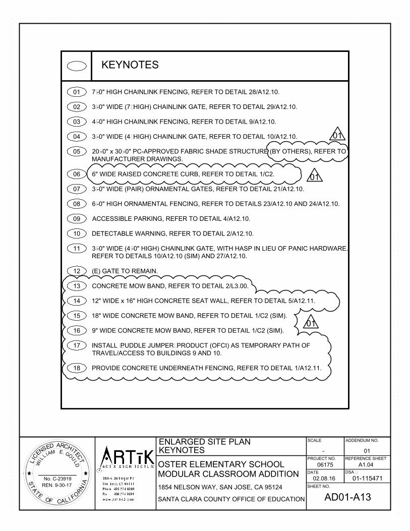
OSTER ELEMENTARY SCHOOL
SANTA CLARA COUNTY OFFICE OF EDUCATION
MODULAR CLASSROOM ADDITION
No. C-23919
REN. 9-30-17
1854 NELSON WAY, SAN JOSE, CA 95124
ADDENDUM NO.
SHEET NO.
REFERENCE SHEET
SCALE
06175
DATE
PROJECT NO.
DSA #
01-115471
ENLARGED SITE PLAN
-
AD01-A13
A1.04
KEYNOTES 01
02.08.16
KEYNOTES
01
02
7'-0" HIGH CHAINLINK FENCING, REFER TO DETAIL 28/A12.10.
3'-0" WIDE (7' HIGH) CHAINLINK GATE, REFER TO DETAIL 29/A12.10.
03 4'-0" HIGH CHAINLINK FENCING, REFER TO DETAIL 9/A12.10.
04 3'-0" WIDE (4' HIGH) CHAINLINK GATE, REFER TO DETAIL 10/A12.10.
05 20'-0" x 30'-0" PC-APPROVED FABRIC SHADE STRUCTURE (BY OTHERS), REFER TO
MANUFACTURER DRAWINGS.
06 6" WIDE RAISED CONCRETE CURB, REFER TO DETAIL 1/C2.
07 3'-0" WIDE (PAIR) ORNAMENTAL GATES, REFER TO DETAIL 21/A12.10.
08 6'-0" HIGH ORNAMENTAL FENCING, REFER TO DETAILS 23/A12.10 AND 24/A12.10.
09 ACCESSIBLE PARKING, REFER TO DETAIL 4/A12.10.
10 DETECTABLE WARNING, REFER TO DETAIL 2/A12.10.
11 3'-0" WIDE (4'-0" HIGH) CHAINLINK GATE, WITH HASP IN LIEU OF PANIC HARDWARE.
REFER TO DETAILS 10/A12.10 (SIM) AND 27/A12.10.
12 (E) GATE TO REMAIN.
13 CONCRETE MOW BAND, REFER TO DETAIL 2/L3.00.
14 12" WIDE x 16" HIGH CONCRETE SEAT WALL, REFER TO DETAIL 5/A12.11.
15 18" WIDE CONCRETE MOW BAND, REFER TO DETAIL 1/C2 (SIM).
16 9" WIDE CONCRETE MOW BAND, REFER TO DETAIL 1/C2 (SIM).
17 INSTALL 'PUDDLE JUMPER' PRODUCT (OFCI) AS TEMPORARY PATH OF
TRAVEL/ACCESS TO BUILDINGS 9 AND 10.
18 PROVIDE CONCRETE UNDERNEATH FENCING, REFER TO DETAIL 1/A12.11.
01
01
01

OSTER ELEMENTARY SCHOOL
SANTA CLARA COUNTY OFFICE OF EDUCATION
MODULAR CLASSROOM ADDITION
No. C-23919
REN. 9-30-17
1854 NELSON WAY, SAN JOSE, CA 95124
ADDENDUM NO.
SHEET NO.
REFERENCE SHEET
SCALE
06175
DATE
PROJECT NO.
DSA #
01-115471
SITE DETAILS
1/4" = 1'-0"
AD01-A14
21/A12.10
01
02.08.16
ORNAMENTAL ENTRY GATES
21
3'-0" 3'-0"
EQ.EQ.
12'-4"
3'-0" 3'-0"
EQ.EQ.
12'-4"
1/2" = 1'-0"
TOP RAIL
3x3 POST
BOTTOM RAIL10" x 1/8" THICK STEEL PLATE
(SMOOTH UNINTERRUPTED) AT
BOTTOM INSIDE FACE OF GATE
TOP RAIL
3x3 POST
BOTTOM RAIL10" x 1/8" THICK STEEL PLATE
(SMOOTH UNINTERRUPTED) AT
BOTTOM INSIDE FACE OF GATE
EXTERIOR GATE ELEVATION
INTERIOR GATE ELEVATION
25
-
TYP.
01
01
01
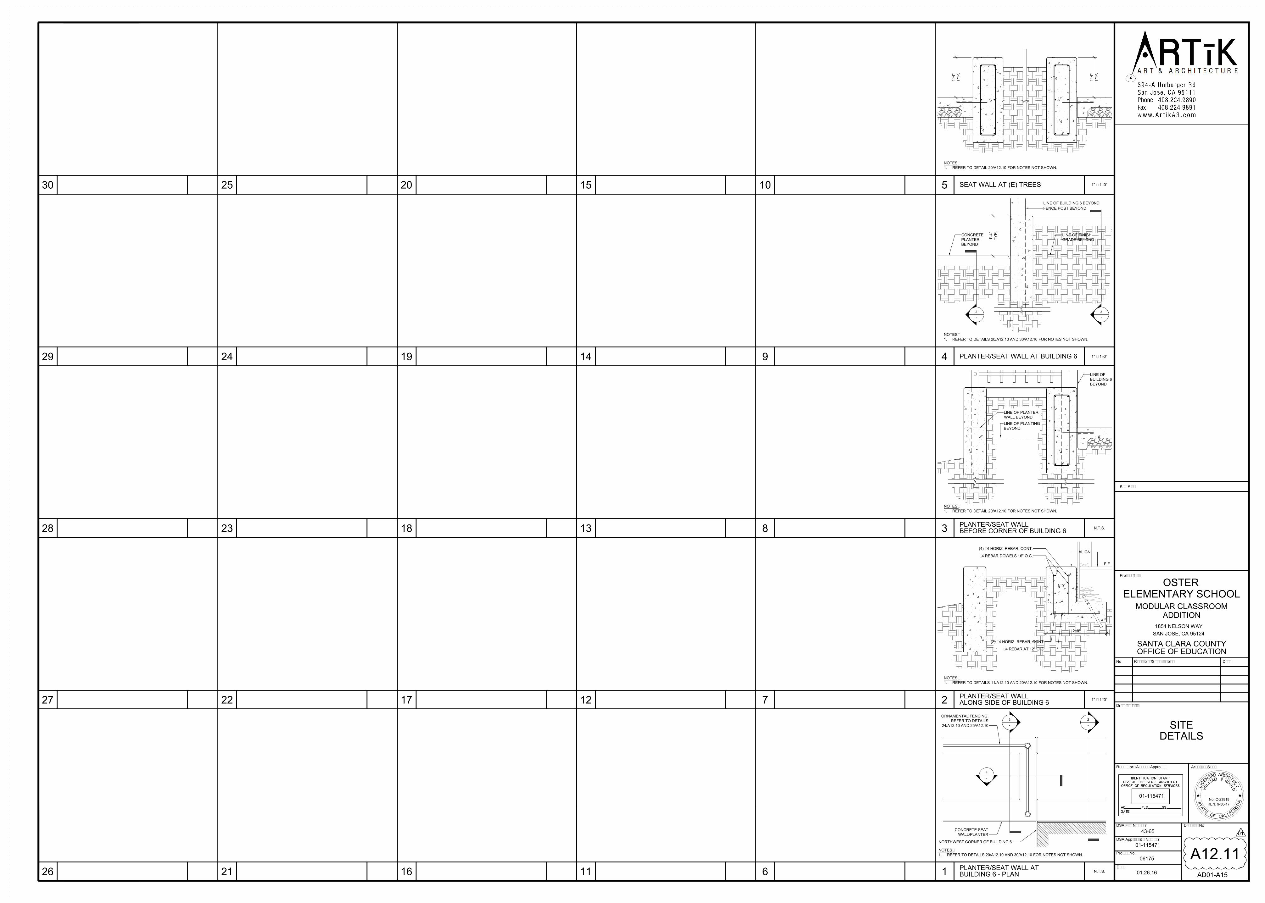
SITE
DETAILS
A12.11
Date
01.26.16
DSA Application Number
DSA File Number
Regulatory Agency Approval
Project No.
43-65
06175
01-115471
Drawing No
01-115471
Architect Seal
SANTA CLARA COUNTY
No
Drawing Title
Revisions/Submissions
1854 NELSON WAY
SAN JOSE, CA 95124
Project Title
Key Plan
Date
No. C-23919
REN. 9-30-17
OFFICE OF EDUCATION
OSTER
ELEMENTARY SCHOOL
MODULAR CLASSROOM
ADDITION
26 21
27
28 23
11
12
29
30
24
25 20
6 1
7
8
2
9 4
5
3
10
1" = 1'-0"
2'-0"
ALIGN
F.F.
(4) #4 HORIZ. REBAR, CONT.
#4 REBAR DOWELS 16" O.C.
#4 REBAR AT 12" O.C.
(2) #4 HORIZ. REBAR, CONT.
1'-0"
NOTES:
1. REFER TO DETAILS 11/A12.10 AND 20/A12.10 FOR NOTES NOT SHOWN.
2
-
N.T.S.
3
-
4
-
NORTHWEST CORNER OF BUILDING 6
CONCRETE SEAT
WALL/PLANTER
ORNAMENTAL FENCING,
REFER TO DETAILS
24/A12.10 AND 25/A12.10
N.T.S.
NOTES:
1. REFER TO DETAIL 20/A12.10 FOR NOTES NOT SHOWN.
LINE OF
BUILDING 6
BEYOND
LINE OF PLANTER
WALL BEYOND
LINE OF PLANTING
BEYOND
1" = 1'-0"
NOTES:
1. REFER TO DETAILS 20/A12.10 AND 30/A12.10 FOR NOTES NOT SHOWN.
LINE OF BUILDING 6 BEYOND
FENCE POST BEYOND
NOTES:
1. REFER TO DETAILS 20/A12.10 AND 30/A12.10 FOR NOTES NOT SHOWN.
CONCRETE
PLANTER
BEYOND
LINE OF FINISH
GRADE BEYOND
2
-
3
-
1" = 1'-0"
NOTES:
1. REFER TO DETAIL 20/A12.10 FOR NOTES NOT SHOWN.
PLANTER/SEAT WALL AT
BUILDING 6 - PLAN
PLANTER/SEAT WALL
ALONG SIDE OF BUILDING 6
PLANTER/SEAT WALL
BEFORE CORNER OF BUILDING 6
PLANTER/SEAT WALL AT BUILDING 6
13
14
15
16
22 17
18
19
SEAT WALL AT (E) TREES
01
AD01-A15
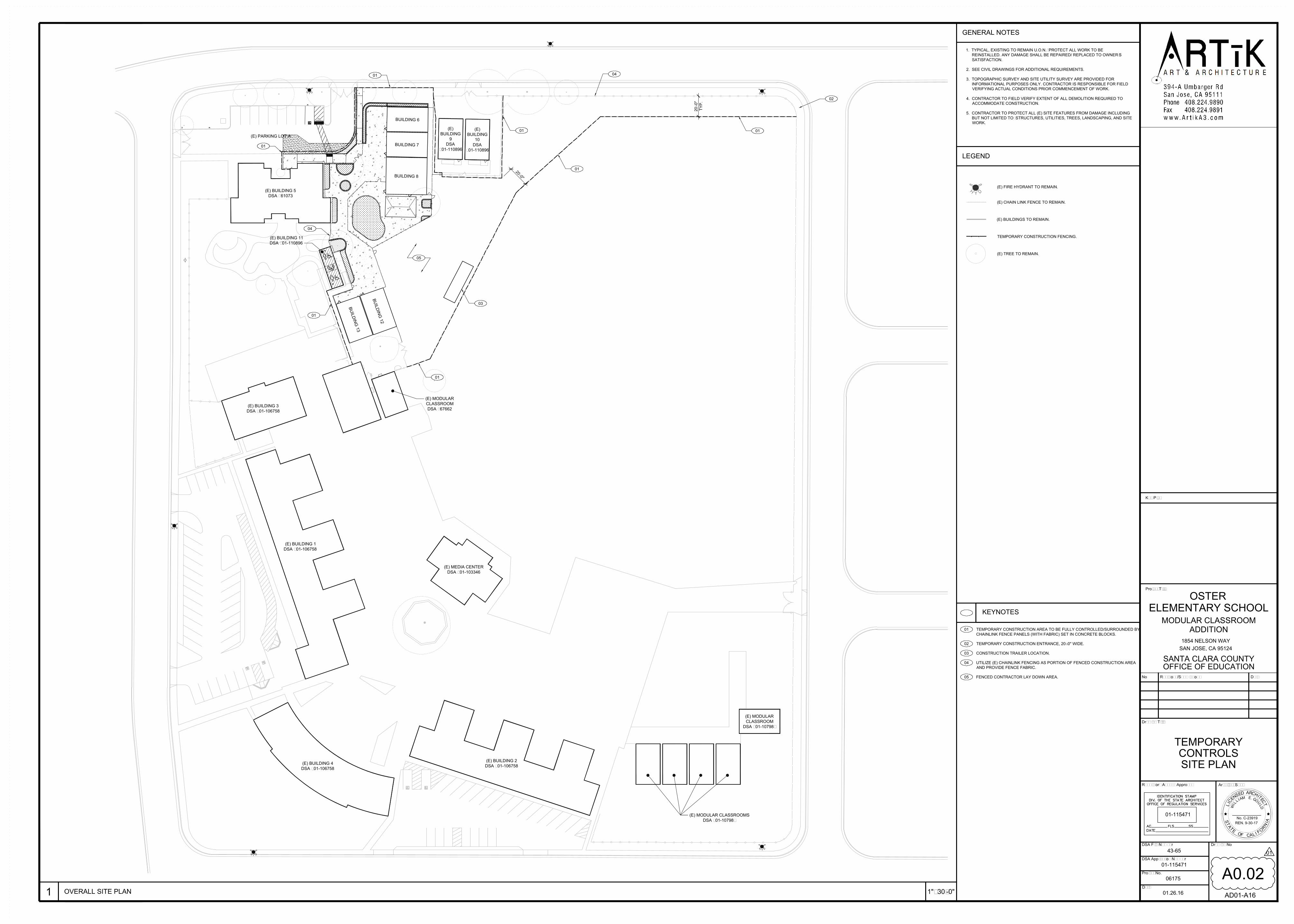
(E)
BUILDING
10
DSA
#01-110896
(E)
BUILDING
9
DSA
#01-110896
(E) BUILDING 5
DSA #61073
B
U
I
L
D
I
N
G
1
3
B
U
I
L
D
I
N
G
1
2
BUILDING 6
BUILDING 7
BUILDING 8
(E) BUILDING 11
DSA #01-110896
NO
PARKING
(E) BUILDING 3
DSA #01-106758
(E) MODULAR
CLASSROOM
DSA #67662
(E) BUILDING 1
DSA #01-106758
(E) MEDIA CENTER
DSA #01-103346
(E) BUILDING 4
DSA #01-106758
(E) BUILDING 2
DSA #01-106758
(E) MODULAR CLASSROOMS
DSA #01-10798?
(E) MODULAR
CLASSROOM
DSA #01-10798?
(E) PARKING LOT A
60" x 60"
CLR. AND
LEVEL
XXXXXXXXXXXXXXXXXXXXXXXXXXXXXX
X
X
X
X
X
X
X
X
X
X
X
X
X
X
X
X
X
X
X
X
X
X
X
X
X
X
X
X
X
X
X
X
X
X
X
X
X
X
X
X
X
X
X
X
X
X
X
X
X
X
X
X
X
X
X
X
X
X
X
X
XX
X X X X X X X
X
X
X
X
XX
XX
XX
X X X X X X X X X X X X
X
X
X
X
X
X
X
X
X
X
XX
X
XX
X
XX
X
X
XX
XX
XX
XX
XX
XX
XX
2
0
'
-
0
"
20
'-0
"
TY
P.
04
02
03
01
05
01
01
01
01
01
04
01
1
OVERALL SITE PLAN
TEMPORARY
CONTROLS
SITE PLAN
A0.02
1"=30'-0"
Date
01.26.16
DSA Application Number
DSA File Number
Regulatory Agency Approval
Project No.
43-65
06175
01-115471
Drawing No
01-115471
Architect Seal
SANTA CLARA COUNTY
No
Drawing Title
Revisions/Submissions
1854 NELSON WAY
SAN JOSE, CA 95124
Project Title
Key Plan
Date
No. C-23919
REN. 9-30-17
OFFICE OF EDUCATION
OSTER
ELEMENTARY SCHOOL
MODULAR CLASSROOM
ADDITION
GENERAL NOTES
1. TYPICAL, EXISTING TO REMAIN U.O.N.; PROTECT ALL WORK TO BE
REINSTALLED. ANY DAMAGE SHALL BE REPAIRED/ REPLACED TO OWNER'S
SATISFACTION.
2. SEE CIVIL DRAWINGS FOR ADDITIONAL REQUIREMENTS.
3. TOPOGRAPHIC SURVEY AND SITE UTILITY SURVEY ARE PROVIDED FOR
INFORMATIONAL PURPOSES ONLY. CONTRACTOR IS RESPONSIBLE FOR FIELD
VERIFYING ACTUAL CONDITIONS PRIOR COMMENCEMENT OF WORK.
4. CONTRACTOR TO FIELD VERIFY EXTENT OF ALL DEMOLITION REQUIRED TO
ACCOMMODATE CONSTRUCTION.
5. CONTRACTOR TO PROTECT ALL (E) SITE FEATURES FROM DAMAGE INCLUDING
BUT NOT LIMITED TO: STRUCTURES, UTILITIES, TREES, LANDSCAPING, AND SITE
WORK.
(E) FIRE HYDRANT TO REMAIN.
TEMPORARY CONSTRUCTION FENCING.
(E) CHAIN LINK FENCE TO REMAIN.
(E) TREE TO REMAIN.
LEGEND
(E) BUILDINGS TO REMAIN.
KEYNOTES
01
TEMPORARY CONSTRUCTION ENTRANCE, 20'-0" WIDE.02
CONSTRUCTION TRAILER LOCATION.03
04 UTILIZE (E) CHAINLINK FENCING AS PORTION OF FENCED CONSTRUCTION AREA
AND PROVIDE FENCE FABRIC.
TEMPORARY CONSTRUCTION AREA TO BE FULLY CONTROLLED/SURROUNDED BY
CHAINLINK FENCE PANELS (WITH FABRIC) SET IN CONCRETE BLOCKS.
05 FENCED CONTRACTOR LAY DOWN AREA.
01
AD01-A16
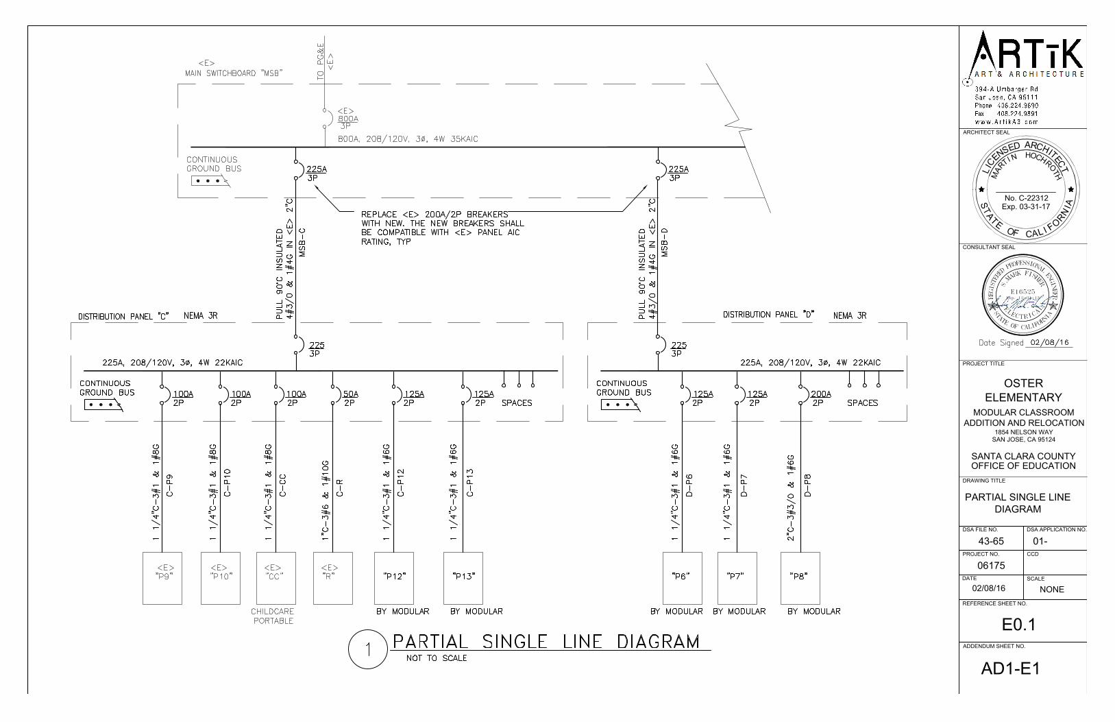
ADDENDUM SHEET NO.
OSTER
SCALE
REFERENCE SHEET NO.
CCDPROJECT NO.
43-65
DATE
06175
SANTA CLARA COUNTY
SAN JOSE, CA 95124
1854 NELSON WAY
ELEMENTARY
DRAWING TITLE
PROJECT TITLE
CONSULTANT SEAL
ARCHITECT SEAL
OFFICE OF EDUCATION
DSA APPLICATION NO.DSA FILE NO.
01-
T
A
I
C
S
L
No. C-22312
Exp. 03-31-17
L
E
F
O
AC
T
F
I
N
R
O
I
A
C
E
E
N
S
D
RA
E
T
C
T
I
H
H
M
H
R
O
O
C
N
I
T
A
R
H
T
02/08/16
NONE
AD1-E1
PARTIAL SINGLE LINE
DIAGRAM
RKFI HERS.
M
AINROFILACFOETA
TS
REENIG
NE
LANOISSEFORPDERETSIGE R
E16525Exp. 12-31-13
A
ELECTRICA
L
S
E0.1
MODULAR CLASSROOM
ADDITION AND RELOCATION

(E
)
BU
IL
DIN
G
10
DS
A
#0
1-1
10
89
6
(E
)
BU
IL
DIN
G
9
DS
A
#0
1-1
10
89
6
(E
) B
UIL
DIN
G 5
DS
A #
61
07
3
B
U
I
L
D
I
N
G
1
3
D
S
A
#
0
1
-
B
U
I
L
D
I
N
G
1
2
D
S
A
#
0
1
-
BU
ILD
IN
G 6
DS
A #02-113876
BU
ILD
IN
G 7
DS
A #01-
BU
ILD
IN
G 8
DS
A #01-
(E
) B
UIL
DIN
G 1
1
DS
A #
01
-1
10
89
6
PLA
YG
RO
UN
D
(P
OU
RE
D-IN
-P
LA
CE
RU
BB
ER
S
UR
FA
CE
)
PLA
YG
RO
UN
D
OU
TD
OO
R
LE
AR
NIN
G A
RE
A
(D
EC
OM
PO
SE
D
GR
AN
IT
E)
PR
E-S
CH
OO
L
PLA
YG
RO
UN
D
16" H
IG
H R
AIS
ED
PLA
NT
ER
/S
EA
T W
ALL
NO
PA
RK
IN
G
ADDENDUM SHEET NO.
OSTER
SCALE
REFERENCE SHEET NO.
CCDPROJECT NO.
43-65
DATE
06175
SANTA CLARA COUNTY
SAN JOSE, CA 95124
1854 NELSON WAY
ELEMENTARY
DRAWING TITLE
PROJECT TITLE
CONSULTANT SEAL
ARCHITECT SEAL
OFFICE OF EDUCATION
DSA APPLICATION NO.DSA FILE NO.
01-
T
A
I
C
S
L
No. C-22312
Exp. 03-31-17
L
E
F
O
AC
T
F
I
N
R
O
I
A
C
E
E
N
S
D
RA
E
T
C
T
I
H
H
M
H
R
O
O
C
N
I
T
A
R
H
T
02/08/16
1"=50'-0"
AD1-E2
ELECTRICAL SITE
PLAN
RKFI HERS.
M
AINROFILACFOETA
TS
REENIG
NE
LANOISSEFORPDERETSIGE R
E16525Exp. 12-31-13
A
ELECTRICA
L
S
02/08/16
E1.1
MODULAR CLASSROOM
ADDITION AND RELOCATION

H
H
6
CLASSROOM
AREA : 827 SF
OCCUP : E
OLF : 20
OL : 20
H
H
7
CLASSROOM
H
H
12
CLASSROOM
H
H
13
CLASSROOM
AREA : 827 SF
OCCUP : E
OLF : 20
OL : 20
AREA : 827 SF
OCCUP : E
OLF : 20
OL : 20
AREA : 827 SF
OCCUP : E
OLF : 20
OL : 20
H
H
H
H
WH
8
CLASSROOM
AREA : 828 SF
OCCUP : E
OLF : 20
OL : 20
ADDENDUM SHEET NO.
OSTER
SCALE
REFERENCE SHEET NO.
CCDPROJECT NO.
43-65
DATE
06175
SANTA CLARA COUNTY
SAN JOSE, CA 95124
1854 NELSON WAY
ELEMENTARY
DRAWING TITLE
PROJECT TITLE
CONSULTANT SEAL
ARCHITECT SEAL
OFFICE OF EDUCATION
DSA APPLICATION NO.DSA FILE NO.
01-
T
A
I
C
S
L
No. C-22312
Exp. 03-31-17
L
E
F
O
AC
T
F
I
N
R
O
I
A
C
E
E
N
S
D
RA
E
T
C
T
I
H
H
M
H
R
O
O
C
N
I
T
A
R
H
T
02/08/16
1/16"=1'-0"
AD1-E3
ELECTRICAL PLAN
RKFI HERS.
M
AINROFILACFOETA
TS
REENIG
NE
LANOISSEFORPDERETSIGE R
E16525Exp. 12-31-13
A
ELECTRICA
L
S
E2.1
MODULAR CLASSROOM
ADDITION AND RELOCATIONELECTRICAL PLAN
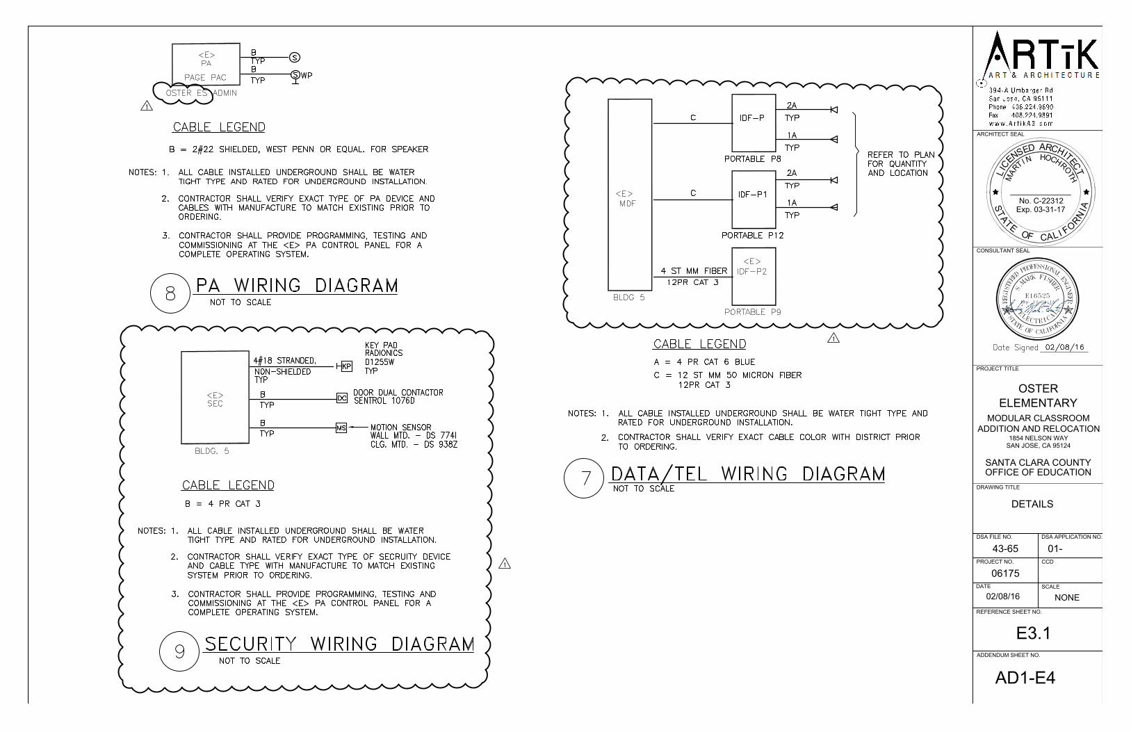
ADDENDUM SHEET NO.
OSTER
SCALE
REFERENCE SHEET NO.
CCDPROJECT NO.
43-65
DATE
06175
SANTA CLARA COUNTY
SAN JOSE, CA 95124
1854 NELSON WAY
ELEMENTARY
DRAWING TITLE
PROJECT TITLE
CONSULTANT SEAL
ARCHITECT SEAL
OFFICE OF EDUCATION
DSA APPLICATION NO.DSA FILE NO.
01-
T
A
I
C
S
L
No. C-22312
Exp. 03-31-17
L
E
F
O
AC
T
F
I
N
R
O
I
A
C
E
E
N
S
D
RA
E
T
C
T
I
H
H
M
H
R
O
O
C
N
I
T
A
R
H
T
02/08/16
NONE
AD1-E4
DETAILS
RKFI HERS.
M
AINROFILACFOETA
TS
REENIG
NE
LANOISSEFORPDERETSIGE R
E16525Exp. 12-31-13
A
ELECTRICA
L
S
E3.1
MODULAR CLASSROOM
ADDITION AND RELOCATION

ADDENDUM SHEET NO.
OSTER
SCALE
REFERENCE SHEET NO.
CCDPROJECT NO.
43-65
DATE
06175
SANTA CLARA COUNTY
SAN JOSE, CA 95124
1854 NELSON WAY
ELEMENTARY
DRAWING TITLE
PROJECT TITLE
CONSULTANT SEAL
ARCHITECT SEAL
OFFICE OF EDUCATION
DSA APPLICATION NO.DSA FILE NO.
01-
T
A
I
C
S
L
No. C-22312
Exp. 03-31-17
L
E
F
O
AC
T
F
I
N
R
O
I
A
C
E
E
N
S
D
RA
E
T
C
T
I
H
H
M
H
R
O
O
C
N
I
T
A
R
H
T
02/08/16
NONE
AD1-E5
FIRE ALARM DETAILS
RKFI HERS.
M
AINROFILACFOETA
TS
REENIG
NE
LANOISSEFORPDERETSIGE R
E16525Exp. 12-31-13
A
ELECTRICA
L
S
02/08/16
E4.1
MODULAR CLASSROOM
ADDITION AND RELOCATION
OSTER ELEMENTARY SCHOOL SCCOE PORTABLES
FACP @ ADMIN
DEVICE TOTAL TOTAL
SUPEVISORY SUPERVISORY ALARM ALARM
MODEL DESCRIPTIONQTY <E> QTY <N>
CURRENT CURRENT CURRENT CURRENT
SIMPLEX 4100 FACP 0 1 0.417 0.4170 0.77 0.7700
SIMPLEX 4003EC LIFEALARM FIRE ALARM CONTROL 0 1 0.13 0.1300 0.12 0.1200
SIMPLEX 4009 NAC REMOTE POWER SUPPLY 0 1 0.085 0.0850 0.185 0.1850
SIMPLEX 4098-9714 SMOKE DETECTORS 0 19 0.0004 0.0076 0.001 0.0190
SIMPLEX 4098-9733 HEAT DETECTORS 0 20 0.0004 0.0080 0.001 0.0200
SIMPLEX 4098-9756 DUCT SMOKE DETECTORS 0 0 0.003 0.0000 0.015 0.0000
SIMPLEX 4099-9001 PULL STATION 0 0 0.00037 0.0000 0.002 0.0000
TOTAL SYSTEM 0.6476 TOTAL SYSTEM 1.114
STANDBY ALARM
CURRENT (AMP) CURREN (AMP)
STANDBY
PERIOD 24HR. 24 ALARM PERIOD 15 MIM. 0.25
REQUIRED
STANDBY
CAPACITY 15.5424REQUIRED ALARM CAPACITY
0.2785
TOTAL REQUIRED
CAPACITY (AMP-HOURS)
15.8209
SAFTEY MARGIN (20%)
3.1642
REQUIRED BATTERY
CAPACITY (AMP-HOURS)
18.9851
EXISTING BATTERY SIZE 33 AH

A R T & A R C H I T E C T U RE
394-A Umbarge r Rd
San Jose, CA 95111
Phone 408.224.9890
Fax 408.224.9891
w w w. A r t i k A 3 . c o m
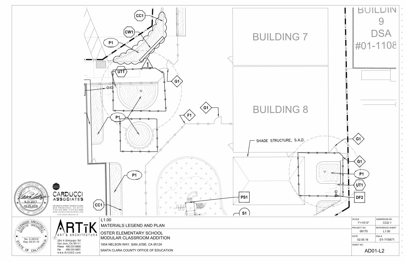
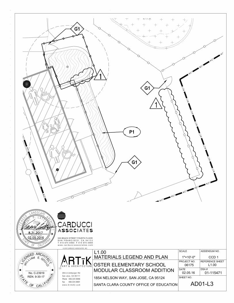
A R T & A R C H I T E C T U RE
394-A Umbarge r Rd
San Jose, CA 95111
Phone 408.224.9890
Fax 408.224.9891
w w w. A r t i k A 3 . c o m
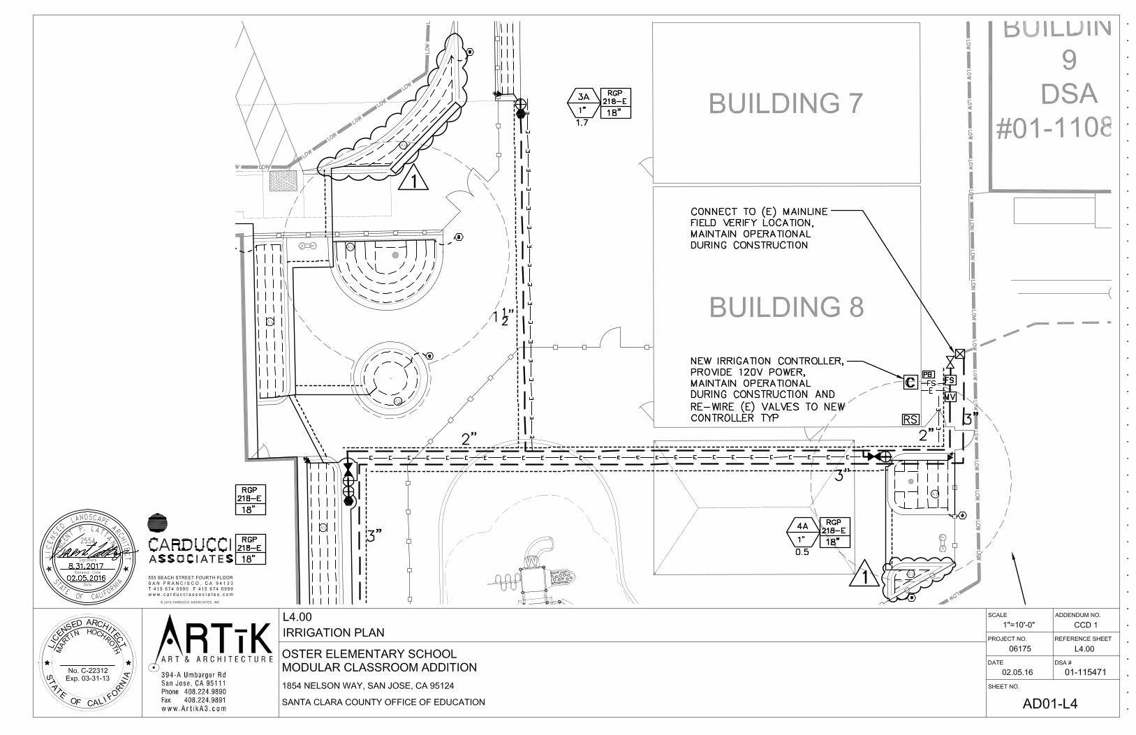

A R T & A R C H I T E C T U RE
394-A Umbarge r Rd
San Jose, CA 95111
Phone 408.224.9890
Fax 408.224.9891
w w w. A r t i k A 3 . c o m

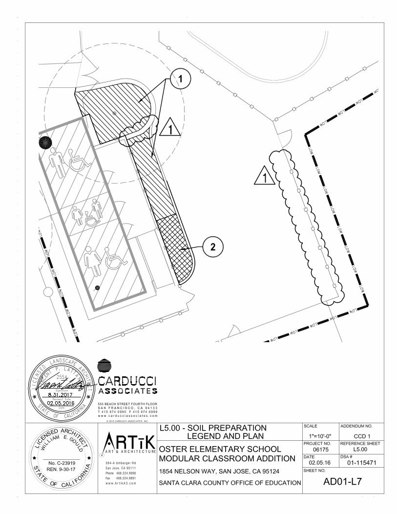
A R T & A R C H I T E C T U RE
394-A Umbarge r Rd
San Jose, CA 95111
Phone 408.224.9890
Fax 408.224.9891
w w w. A r t i k A 3 . c o m
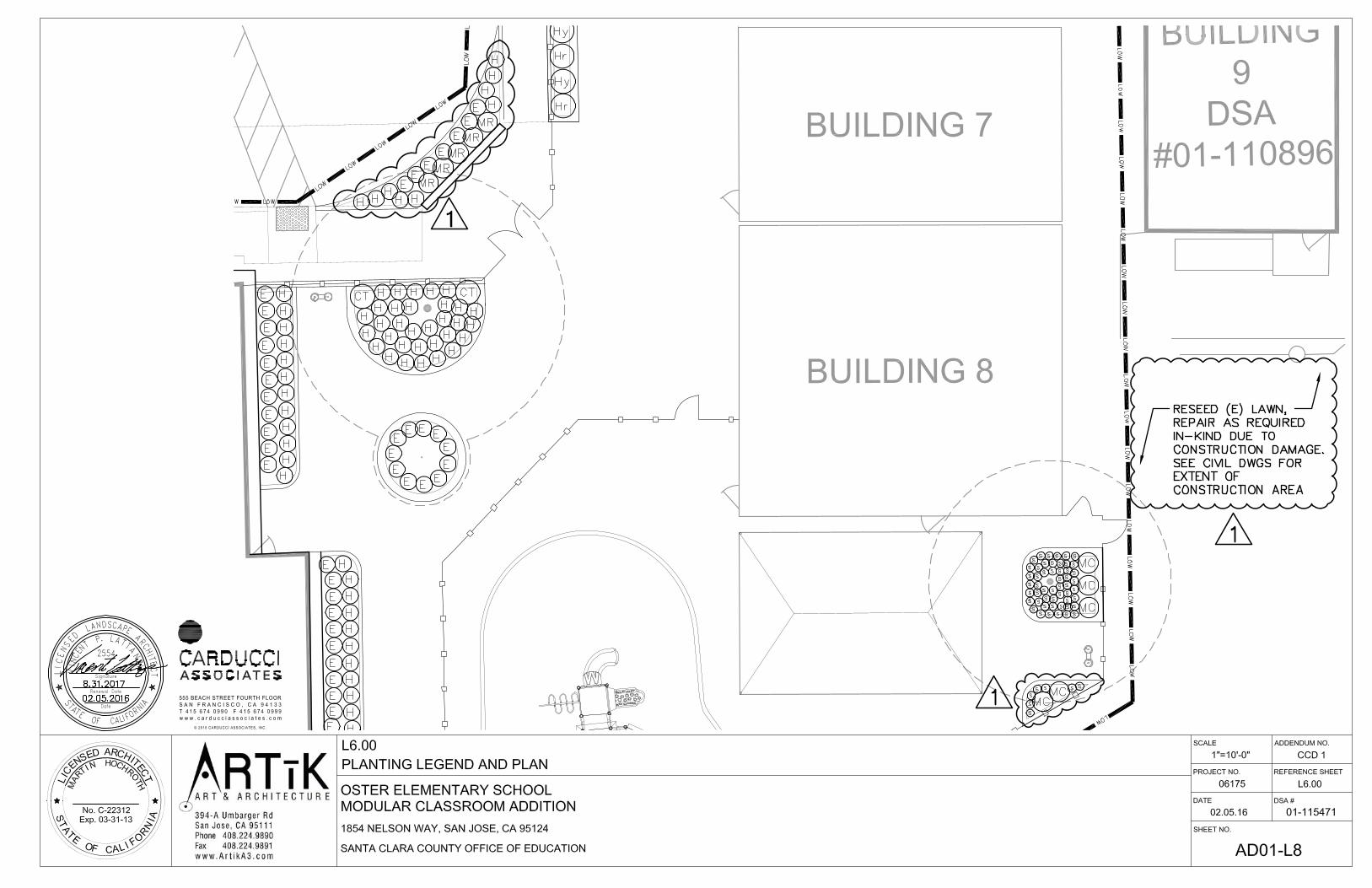
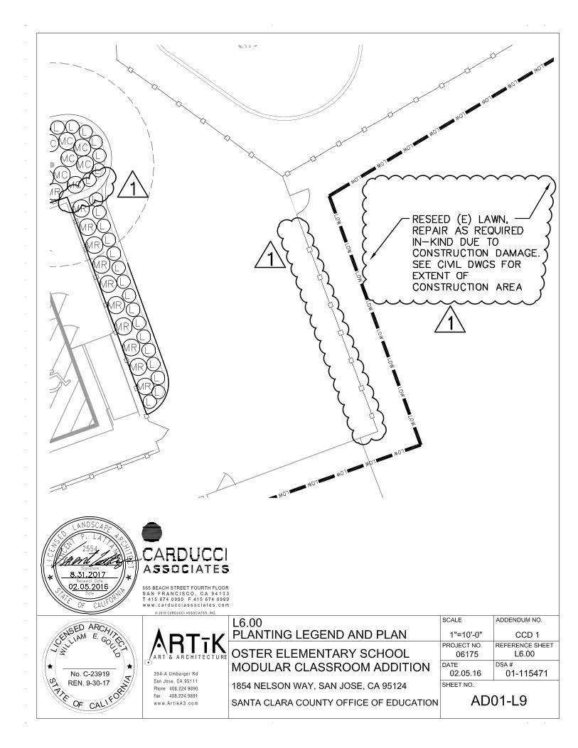
A R T & A R C H I T E C T U RE
394-A Umbarge r Rd
San Jose, CA 95111
Phone 408.224.9890
Fax 408.224.9891
w w w. A r t i k A 3 . c o m