addendum no: 3 · a. a2.4, standard symbols for welding, brazing, and nondestructive examination....
TRANSCRIPT
Purchasing Services Post Office Box 2570
Waco, Texas 76702-2570 Phone: 254 / 750-8405
Fax: 254 / 750-8063 [email protected]
CITY OF WACO www.waco-texas.com
Date: 10/16/2017 RFB No: 2017-059 Commodity: Water Transmission Line Riverside WTP to Gholson GST Buyer: Kasey Gamblin
Closing Time: 2:00 P.M. CST, October 26, 2017 Opening Time: 2:01 P.M. CST, October 26, 2017
Bid Opening Location: Operations Center, Purchasing Services Office, 1415 N. 4th St., Waco, TX 76707
______________________________________________________ Addendum No: 3
The above-mentioned Bid invitation has been changed in the following manner. Sign and return addendum to the Purchasing Office by the closing time and date with your RFB response. Returning this page signed by your authorized agent will serve to acknowledge this change. All other requirements of the invitation remain unchanged. If you have any questions, please call or stop by the Purchasing Office at the above address.
Questions and Clarifications:
PLEASE SEE THE FOLLOWING PAGES BELOW
Firm:_____________________________________________________________________________________ Address___________________________________________________________________________________ Signature of Person Authorized to Sign Proposal:______________________________________________________________________ Signor's Name and Title (print or type):_____________________________________________________________________________ E-mail Address:____________________________________________________________________________ Date:____________________Telephone:___________________________Fax:_________________________
RFB 2017-059 Water Transmission Line Riverside WTP to Gholson GST
1 of 26
RFB 2017-059 Water Transmission Line Riverside WTP to Gholson GST
2 of 26

RFB 2017-059 Water Transmission Line Riverside WTP to Gholson GST
3 of 26

Bar-Wrapped Concrete Cylinder Pipe and Fittings 33 11 13 - 1
SECTION 33 11 13
BAR-WRAPPED CONCRETE CYLINDER PIPE AND FITTINGS PART 1 GENERAL 1.01 REFERENCES
A. The following is a list of standards which may be referenced in this Section but are not limited to: 1. American Society for Nondestructive Testing: SNT-TC-1A,Personnel
Qualification and Certification of Non-Destructive Testing. 2. Most current edition of the American Society of Mechanical Engineers (ASME)
Boiler and Pressure Vessel Code, (a) Section V, Nondestructive Examination, (b) Section VIII, Pressure Vessels, (c) Section IX, Welding and Brazing Qualifications, (d) Part QW Welding.
3. American Water Works Association (AWWA): a. C200, Steel Water Pipe—6” and Larger. b. C205, Cement-Mortar Protective Lining and Coating for Steel Water
Pipe—4” and Larger—Shop Applied. c. C206, Field Welding of Steel Water Pipe. d. C207, Steel Pipe Flanges for Waterworks Service—Sizes 4” through
144”. e. C208, Dimensions for Fabricated Steel Water Pipe Fittings. f. C303, Concrete Pressure Pipe, Bar-Wrapped, Steel-Cylinder Type. g. M9, Concrete Pressure Pipe, most current edition. h. M11, Steel Water Pipe: A Guide for Design and Installation, most
current edition. 4. American Welding Society (AWS):
a. A2.4, Standard Symbols for Welding, Brazing, and Nondestructive Examination.
b. A3.0, Standard Welding Terms and Definitions Including Terms for Adhesive Bonding, Brazing, Soldering, Thermal Cutting, and Thermal Spraying.
c. D1.1/D1.1M, Structural Welding Code—Steel. d. D1.3, Structural Welding Code—Sheet Steel. e. D1.4, Structural Welding Code—Reinforcing Steel. f. QC1, Standard for AWS Certification of Welding Inspectors.
5. ASTM International (ASTM): a. A675/A675M, Standard Specification for Steel Bars, Carbon, Hot-
Wrought, Special Quality, Mechanical Properties. b. E329, Standard Specification for Agencies Engaged in Construction
Inspection and/or Testing. 6. International Organization for Standardization (ISO): ISO 9001:2000, Quality
Management Systems—Requirements. 7. Lloyd’s Register requirements.
1.02 DEFINITIONS
A. Fittings and Specials: Including, but not limited to fittings, closure pieces, bends, elbows, reducers, tees, wyes, bifurcations, crosses, outlets, manifolds, nozzles, wall sleeves,
RFB 2017-059 Water Transmission Line Riverside WTP to Gholson GST
4 of 26
Bar-Wrapped Concrete Cylinder Pipe and Fittings 33 11 13 - 2
bulkheads, and other piping and appurtenances fabricated from steel plate, sheet, or coils as required to provide Work, complete. Specials shall also include piping above ground or inside structures.
B. Acronyms:
1. CJP: Complete Joint Penetration. 2. CWI: Certified Welding Inspector. 3. MT: Magnetic Particle Testing. 4. NDE: Nondestructive Examination. 5. NDT: Nondestructive Testing. 6. PJP: Partial Joint Penetration. 7. PQR: Procedure Qualification Record. 8. PT: Liquid Penetrant Testing. 9. RT: Radiographic Testing. 10. UT: Ultrasonic Testing. 11. VT: Visual Testing. 12. WPQ: Welder/Welding Operator Performance Qualification. 13. WPS: Welding Procedure Specification.
1.03 DESIGN REQUIREMENTS
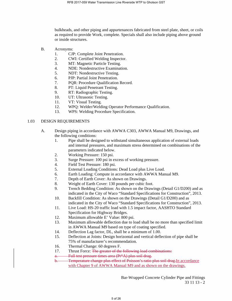
A. Design piping in accordance with AWWA C303, AWWA Manual M9, Drawings, and the following conditions: 1. Pipe shall be designed to withstand simultaneous application of external loads
and internal pressures, and maximum stress determined on combinations of the parameters indicated below.
2. Working Pressure: 150 psi. 3. Surge Pressure: 100 psi in excess of working pressure. 4. Field Test Pressure: 180 psi. 5. External Loading Conditions: Dead Load plus Live Load. 6. Earth Loading: Compute in accordance with AWWA Manual M9. 7. Depth of Earth Cover: As shown on Drawings. 8. Weight of Earth Cover: 130 pounds per cubic foot. 9. Trench Bedding Condition: As shown on the Drawings (Detail G1/D200) and as
indicated in the City of Waco “Standard Specifications for Construction”, 2013. 10. Backfill Condition: As shown on the Drawings (Detail G1/D200) and as
indicated in the City of Waco “Standard Specifications for Construction”, 2013. 11. Live Load: HS-20 traffic load with 1.5 impact factor, AASHTO Standard
Specification for Highway Bridges. 12. Maximum allowable E’ Value: 800 psi. 13. Maximum allowable deflection due to load shall be no more than specified limit
in AWWA Manual M9 based on type of coating specified. 14. Deflection Lag factor, DL, shall be a minimum of 1.00. 15. Deflection at Joints: Design horizontal and vertical deflection of pipe shall be
75% of manufacturer’s recommendation. 16. Thermal Change: 60 degrees F. 17. Thrust Force: The greater of the following load combinations: a. Full test pressure times area (Pt*A) plus soil drag. b. Temperature change plus effect of Poisson’s ratio plus soil drag.In accordance
with Chapter 9 of AWWA Manual M9 and as shown on the drawings.
RFB 2017-059 Water Transmission Line Riverside WTP to Gholson GST
5 of 26
Bar-Wrapped Concrete Cylinder Pipe and Fittings 33 11 13 - 3
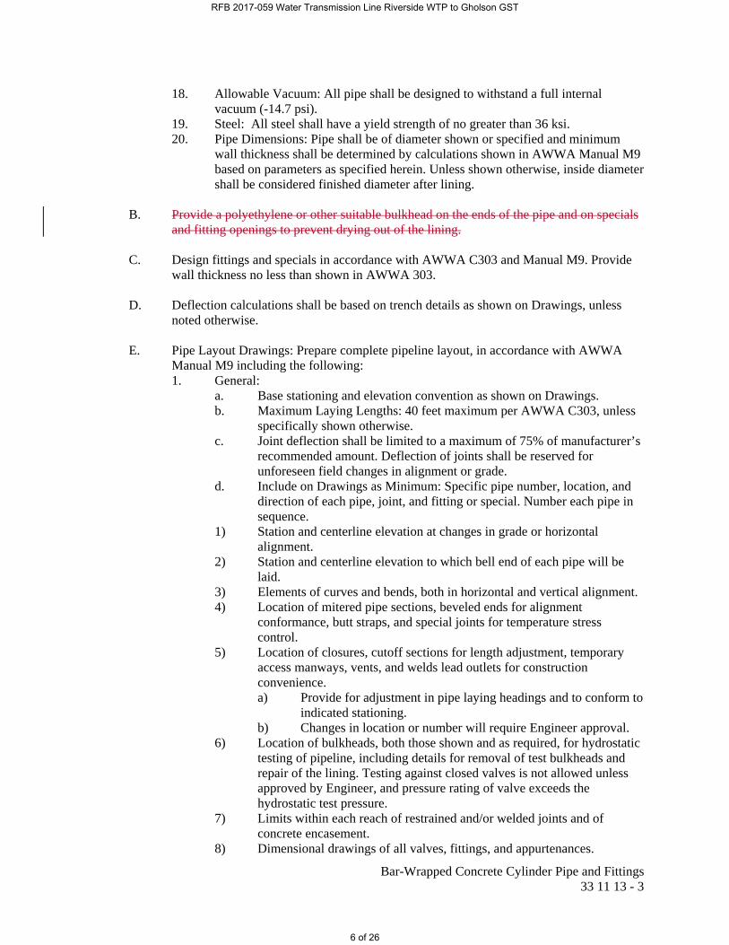
18. Allowable Vacuum: All pipe shall be designed to withstand a full internal vacuum (-14.7 psi).
19. Steel: All steel shall have a yield strength of no greater than 36 ksi. 20. Pipe Dimensions: Pipe shall be of diameter shown or specified and minimum
wall thickness shall be determined by calculations shown in AWWA Manual M9 based on parameters as specified herein. Unless shown otherwise, inside diameter shall be considered finished diameter after lining.
B. Provide a polyethylene or other suitable bulkhead on the ends of the pipe and on specials
and fitting openings to prevent drying out of the lining. C. Design fittings and specials in accordance with AWWA C303 and Manual M9. Provide
wall thickness no less than shown in AWWA 303. D. Deflection calculations shall be based on trench details as shown on Drawings, unless
noted otherwise. E. Pipe Layout Drawings: Prepare complete pipeline layout, in accordance with AWWA
Manual M9 including the following: 1. General:
a. Base stationing and elevation convention as shown on Drawings. b. Maximum Laying Lengths: 40 feet maximum per AWWA C303, unless
specifically shown otherwise. c. Joint deflection shall be limited to a maximum of 75% of manufacturer’s
recommended amount. Deflection of joints shall be reserved for unforeseen field changes in alignment or grade.
d. Include on Drawings as Minimum: Specific pipe number, location, and direction of each pipe, joint, and fitting or special. Number each pipe in sequence.
1) Station and centerline elevation at changes in grade or horizontal alignment.
2) Station and centerline elevation to which bell end of each pipe will be laid.
3) Elements of curves and bends, both in horizontal and vertical alignment. 4) Location of mitered pipe sections, beveled ends for alignment
conformance, butt straps, and special joints for temperature stress control.
5) Location of closures, cutoff sections for length adjustment, temporary access manways, vents, and welds lead outlets for construction convenience. a) Provide for adjustment in pipe laying headings and to conform to
indicated stationing. b) Changes in location or number will require Engineer approval.
6) Location of bulkheads, both those shown and as required, for hydrostatic testing of pipeline, including details for removal of test bulkheads and repair of the lining. Testing against closed valves is not allowed unless approved by Engineer, and pressure rating of valve exceeds the hydrostatic test pressure.
7) Limits within each reach of restrained and/or welded joints and of concrete encasement.
8) Dimensional drawings of all valves, fittings, and appurtenances.
RFB 2017-059 Water Transmission Line Riverside WTP to Gholson GST
6 of 26
Bar-Wrapped Concrete Cylinder Pipe and Fittings 33 11 13 - 4
F. Welding Procedure Specification (WPS):
1. Welding of steel cylinders shall be qualified by testing in accordance with ASME BPVC SEC IX for shop welds and AWS D1.1/D1.1M for field welds.
2. Shop welding of reinforcing steel shall be qualified per AWS D1.4. 3. Shop welding of sheet steel, less than 1/8” thickness, shall be qualified per AWS
D1.3. 4. PQRs conducted on unlisted base metal (most coil products are unlisted base
metals) to be production welded as required in referenced welding code shall be traceable to heat lots.
5. Written WPS required for welds, both shop and field. G. Stulling (Strutting):
1. Designed and provided by pipe manufacturer on specials, fittings, and straight pipe so as to avoid damage to pipe and fittings during handling, storage, hauling, and installation as required by Manufacturer requirements.
1.04 SUBMITTALS
A. Action Submittals:
1. Shop Drawings: a. Design calculations for pipe, reinforcing, fittings, specials, welding, and
joints, including the following: 1) Cylinder thickness, bar wrap diameter and spacing for each pipe
pressure and load classification design. 2) Manufacturing tolerances. 3) Maximum angular deflection limitations of field joints. 4) All other pertinent information required for manufacture and
installation of product specified. b. Complete data and fabrication plans and details for pipe, fittings, and
joints, including all reinforcement dimensions and spacing. c. Design calculations shall include a complete stress analysis of each
section of pipe wall, girth joints, restrained joints, and bell and spigot joints, all sufficient to ascertain conformance of pipe and fittings with the specifications. Joint details and design calculations shall be submitted for all welded joint types, including beveled ends for alignment conformance and deep butt strap joints for pipeline restraint and control of temperature stresses.
d. Certified pipeline layout drawings, compatible with the requirements of AWWA Manual M-9, showing specific number of each pipe and fitting and the location of each pipe section, and direction of each fitting on completed line including the following: 1) Closure sections and cutoffs for field length adjustment. 2) Bulkheads, including details for removal of test bulkheads and
repair of lining. 3) Weld lead outlets and plugs. 4) Stulling size, spacing, and layout, and other methods proposed
for pipe support and handling during manufacturing, transport, and installation. Submit design calculations, drawings, and documentation supporting and confirming that handling and
RFB 2017-059 Water Transmission Line Riverside WTP to Gholson GST
7 of 26

Bar-Wrapped Concrete Cylinder Pipe and Fittings 33 11 13 - 5
support systems have been designed appropriate for methods to be used on this Project.
5) Station and centerline elevation to which bell end of each pipe will be laid.
6) All elements of curves and bends, both in horizontal and vertical alignment.
7) Limits of each reach of restrained and/or welded joints and of concrete encasement.
8) Location of all beveled ends for alignment conformance and deep butt strap joints for temperature stress control.
9) Dimensional drawings of all valves, fittings, and appurtenances. 10) Submit final line layout drawings with project record documents.
Record layout drawings shall indicate actual locations of components within pipeline that are required by this Section to be included in line layout drawings.
e. Type and amount of concrete admixtures. f. Welding procedure specifications. g. Proposed thrust restraint system for restrained joints including drawing
details, materials, calculations, assembly ratings, and pipe attachment methods.
h. Dissimilar Buried Pipe Joints: Joint types and assembly drawings. i. Coating and lining holdbacks. j. Drawings and calculations shall be sealed by a professional engineer
licensed in the State of Texas. 2. Product data for the following:
a. Pipe: 1) Mill certificates. 2) Material data and steel reinforcement schedules which describe
all materials to be utilized. 3) Chemical and physical test reports showing data consistent with
specified requirements for each heat of steel proposed for use. Records should indicate heat of steel for each pipe joint listed in line layout.
b. Rubber Gasket Joint: 1) Material data. 2) Details with dimensions and fabrication tolerances for both bell
and spigot ends. 3) Performance history or test data.
c. Material for protecting exterior of joints. d. Material for protecting interior of joints.
3. Ground Profile and Utility Locations: a. Prior to preparation of line layouts, Contractor shall verify existing
ground profile and the location and depth of all underground utilities crossing pipeline using centerline stakes set by Contractor at no less than 100 feet intervals. Contractor shall carefully locate and excavate utility, survey, document, and submit this information to Engineer.
b. Engineer shall review this information and if necessary make adjustment to pipeline profile. Any plan sheets that are modified by Engineer shall be reissued to Contractor.
4. Welding Data (Shop and Field):
RFB 2017-059 Water Transmission Line Riverside WTP to Gholson GST
8 of 26
Bar-Wrapped Concrete Cylinder Pipe and Fittings 33 11 13 - 6
a. Show on a weld map, complete information regarding base metal specification designation, location, type, size, and extent of welds with reference called out for WPS and NDE numbers in tail of welding symbol.
b. Distinguish between shop and field welds. c. Indicate, by welding symbols or sketches, details of welded joints and
preparation of base metal. Provide complete joint welding details showing bevels, groove angles, and root openings for all welds. Joints or groups of joints in which welding sequence or technique are especially important shall be carefully controlled to minimize shrinkage stresses and distortion.
d. For pipe fittings, provide a joint weld beveling diagram. Refer to AWS D1.1/D1.1M, Annex G Local Dihedral Angle that can be used to calculate bevels for weld joint details of intersecting pipes.
e. Welding and NDE symbols shall be in accordance with AWS A2.4. f. Welding terms and definitions shall be in accordance with AWS A3.0.
B. Informational Submittals:
1. Manufacturer’s Certificate of Compliance that products furnished meet requirements of this Specification and of all reference standards. Certificates shall also include: a. Compliance with additional requirements included in these Contract
Documents. b. Physical and chemical properties of all steel. c. Hydrostatic test pressures. d. Results of production weld tests. e. Sand, cement, and mortar tests. f. Rubber gasket tests. g. Pipe temperature complies with Specifications prior to and during
welding temperature control joints (including supporting data). h. All welds were performed in conformance with these documents.
2. Manufacturing material test specimens and test reports. 3. Letter from Certified Welding Inspector shall be provided to Engineer certifying
that pipe furnished meets requirements of this Section. 4. Pipe manufacturer’s written Quality Assurance/Control Plan. 5. Statements of Qualification:
a. Pipe manufacturer. b. Fittings and specials fabricator. c. Welders or Welding Operators:
1) Name of welder. 2) Welding procedures/positions for which welder is qualified to
weld. 3) Assigned certification stamp number. 4) Certification date. 5) Current certification status.
d. Certified Welding Inspector. Submit the credentials of Contractor’s CWI and quality control specialists for review prior to starting any welding in the shop or field. Credentials shall include, but not be limited to, American Welding Society QC-1 certification.
e. NDT Quality Control Personnel. NDT Quality Control Personnel shall be certified as required by AWS D1.1 and as specified.
RFB 2017-059 Water Transmission Line Riverside WTP to Gholson GST
9 of 26
Bar-Wrapped Concrete Cylinder Pipe and Fittings 33 11 13 - 7
6. Procedures: a. Shop and Field Welding: At a minimum include a complete welding
code paper trail with linkage to Shop Drawings that includes the following: 1) Written WPS and PQR: Provide complete joint dimensions and
details showing bevels, groove angles, root face, and root openings for welds.
2) Written NDT procedures. 3) Current WPQ shall be submitted for each welder prior to
performing any work in the shop or field. 4) Written description of proposed sequencing of events or special
techniques such as: a) Controlling pipe wall temperature stress during
installation. b) Minimizing distortion of steel. c) Shop-Applied Cement-Mortar Lining: Include
description of machine to be used and list of similar projects where machine was used. Identify pipe size and total footage.
d) Monitoring pipeline temperatures during installation. b. Written weld repair procedures for each shop and field weld for Work. c. Field coating application and repair. d. Field lining application and repair. e. Written consumable control procedure for welding materials
demonstrating: 1) How consumables will be stored to comply with manufacturer’s
written instructions. 2) How consumables, such as welding rod, will be dried in ovens,
prior to use. 3) How consumables that become wet will be reconditioned.
7. Reports: a. Submit all NDT data for each shop and field welded joint. All test data
shall be reviewed and signed by the welding inspector. b. Source Quality Control Test Reports:
1) Hydrostatic testing. 2) Destructive weld testing. 3) Nondestructive weld testing. 4) Steel impact testing using Charpy V-notch method. 5) Coating and lining factory Site visit letter by qualified
manufacturer’s technical representative. c. Field Quality Control Test Reports:
1) Weld tests, including re-examination of repaired welds, on each weld joint for the following tests, as applicable: a) Visual Testing (VT). b) Radiographic Testing (RT). c) Ultrasonic Testing (UT). d) Magnetic Particle Testing (MT). e) Liquid Penetrant Testing (PT). f) Leak Testing (LT).
2) Coating and lining Site inspection letter by qualified technical representative.
RFB 2017-059 Water Transmission Line Riverside WTP to Gholson GST
10 of 26

Bar-Wrapped Concrete Cylinder Pipe and Fittings 33 11 13 - 8
d. Cement-mortar lining compressive strength tests in accordance with AWWA C205.
e. Cement-mortar coating absorption tests in accordance with AWWA C205.
8. Field Hydrostatic Testing Plan: Submit at least 15 days prior to testing and at minimum, include the following: a. Testing dates. b. Piping systems and section(s) to be tested. c. Method of isolation. d. Method of conveying water from source to system being tested. e. Calculation of maximum allowable leakage for piping section(s) to be
tested. 9. Certification of Calibration: Approved testing laboratory certificate if pressure
gauge for hydrostatic test has been previously used. If pressure gauge is new, no certificate is required.
10. Certificate of Proper Installation: Pipe manufacturer’s onsite representative shall provide certificate that pipe was properly installed.
11. Test report documentation. 12. Temperature Stress Control Submittal:
a. Submit proposed sequencing of events to control temperature stresses in pipe wall during installation prior to starting of any field welding.
b. Submit the proposed sequencing of events or special techniques to minimize distortion of steel as may result from shop welding procedures.
c. Submit plan for monitoring pipeline temperatures. 13. Submit production schedule for manufacturing/fabricating pipe for work as part
of Contractor’s CPM schedule. Pipe production schedule shall be included in all versions of the Contractor’s CPM schedule beginning with the first schedule submitted.
14. Detailed drawings indicating loading and shipping procedures that are designed to minimize damage to coating. Submittal must be accepted by Engineer prior to any shipment of pipe.
15. Manufacturer’s written Quality Assurance/Control Program. 16. Contractor must submit all certificates for each portion of Work for which
Contractor is requesting payment before acceptance of such payment will be made.
1.05 QUALITY ASSURANCE
A. Qualifications: 1. Pipe Manufacturer:
a. Experienced in fabricating pipe of similar diameters, lengths, and wall thickness required for Work.
b. Certification by ACPPA Quality Certification Program by Lloyd’s Registry or ISO 9001:2000.
c. Demonstrate current production capability for volume of work required for this Project.
d. Experience shall include successful fabrication to AWWA C303 standards of at least 50,000 linear feet of 24” diameter or larger pipe, with steel cylinder thickness of 0.25” or greater, within past 5-year period.
RFB 2017-059 Water Transmission Line Riverside WTP to Gholson GST
11 of 26

Bar-Wrapped Concrete Cylinder Pipe and Fittings 33 11 13 - 9
e. Experience shall be applicable to fabrication plant facilities and personnel, not company or corporation that currently owns fabrication facility or employs personnel.
f. Credentials shall include reference names; telephone numbers; and descriptions of projects for pipe conforming to AWWA C303 standards. Project descriptions shall include, but not be limited to, length, diameter, wall thickness, steel metallurgy, location of facility where pipe was manufactured/fabricated and key plant personnel involved with the work. Submit names and qualifications of current plant personnel to be used to manufacture/fabricate pipe for Work and experienced staff member proposed for onsite observation. Fabricator or manufacturer shall also demonstrate, using Contractor’s Preliminary CPM schedule, current production capability for the volume of work required for this project.
2. Fittings and Specials Fabricator: a. Experienced in fabricating fittings and specials of similar diameters and
wall thickness required for the Work. b. Certification by ACPPA Quality Certification Program by Lloyd’s
Registry or ISO 9001:2000. c. Demonstrate current production capability for volume of work required
for this Project. d. Experience shall include successful fabrication to AWWA C200/AWWA
C208 AWWA C303 standards of at least 25 fittings of 30” or larger pipe, with wall thickness of 0.25” or greater, within past 5-year period.
e. Experience shall be applicable to fabrication shop facilities and personnel, not company or corporation that currently owns fabrication facility or employs personnel.
f. Verification of experience and production capability will be conducted as part of Bid proposal review process for AWWA C303 pipe and Contractor’s Preliminary CPM schedule. As part of Contractor’s Bidding Documents, submit a letter from pipe manufacturer stating that he can comply with fabrication and delivery of pipe as indicated in Contractor’s Preliminary CPM schedule.
3. Welders and Welding Operators: a. Shop Welders: In accordance with ASME BPVC SEC IX. b. Field Welders: In accordance with AWS D1.1/D1.1M. c. Written WPS shall be required for all welds, both shop and field. WPS’s
qualified per the ASME BPVC shall also include Supplementary Essential Variables for notch-tough welding. All provisions of ANSI/AWS D1.1 pertaining to notch-tough welding shall apply.
4. Certified Welding Inspector (CWI): a. In accordance with AWS QC1, with knowledge of appropriate welding
code for Work. b. After receiving CWI qualification, CWI shall have at least 5 years of
professional experience related to welding inspection similar to Work. 5. NDT Quality Control Personnel:
a. In accordance with requirements of ASNT SNT-TC-1A, Level II. b. After receiving NDT qualification, NDT personnel shall have at least 5
years of professional experience related to NDT inspection similar to Work.
B. Certified Welding Inspector (CWI) for Shop Welding:
RFB 2017-059 Water Transmission Line Riverside WTP to Gholson GST
12 of 26
Bar-Wrapped Concrete Cylinder Pipe and Fittings 33 11 13 - 10
1. In accordance with AWWA C303 and as follows. Testing shall include submitting written documentation of procedures per Section V, and acceptable criteria shall be in accordance with Section VIII of ASME Boiler and Pressure Vessel Code.
2. Responsibilities: a. Verify conformance to use of specified materials and their proper
storage. b. Monitor conformance to approved WPS. c. Monitor conformance to approved NDT procedure specifications. d. Monitor conformance of WPQ. e. Provide 100% visual inspection before, during, and after shop welding. f. Supervise NDT personnel and evaluate test results. g. Maintain records and prepare report confirming results of inspection and
testing. C. Certified Welding Inspector (CWI) for Field Welding:
1. In accordance with AWWA C206, AWS D1.1/D1.1M, and as follows. 2. Responsibilities:
a. Verify conformance to use of specified materials and their proper storage.
b. Monitor conformance to approved WPS. c. Monitor conformance to approved NDT procedure specifications. d. Monitor conformance of WPQ. e. Provide 100% visual inspection before, during, and after field welding. f. Supervise NDT personnel and evaluate test results. g. Maintain records and prepare report confirming results of inspection and
testing. D. Prefabrication Meeting: Hold prior to fabrication of pipe, fittings, or specials between
representatives of Owner, Contractor, Engineer, and pipe fabricator to review the following: 1. Project scope. 2. Submittal requirements. 3. Testing. 4. Inspection responsibilities. 5. Shop welding requirements. 6. Field welding requirements. 7. Shop and field coating and lining requirements. 8. Production and delivery schedule. 9. Other issues pertinent to the Work.
E. Contractor shall be responsible for performing and paying for all tests as specified for the
pipeline. Engineer, at his expense, shall have the right to witness all testing conducted by Contractor; provided that the Contractor’s schedule is not delayed for convenience of Owner.
F. In addition to those tests specifically required, Engineer may request additional samples
of any material including mixed concrete and lining and coating samples for testing additional samples shall be furnished as part of Work.
RFB 2017-059 Water Transmission Line Riverside WTP to Gholson GST
13 of 26
Bar-Wrapped Concrete Cylinder Pipe and Fittings 33 11 13 - 11
G. Onsite Observation: Pipe fabricator shall provide an experienced staff member to be onsite for initial installation of pipe and fittings. Staff member’s duties shall include, but not be limited to, the following: 1. Observe installation and welding of pipe and fittings. 2. Report any concerns to Engineer. 3. Answer questions and provide assistance to Engineer and Contractor. 4. Copies of all field reports and test results shall be submitted in accordance with
Contract Documents. 1.06 DELIVERY, HANDLING, AND STORAGE
A. Pipe Marking: Mark each pipe section in accordance with AWWA C303. In addition, mark each pipe section as follows: 1. Special pipe sections and fittings shall be marked at each end with notation “TOP
FIELD CENTERLINE”. 2. Mark “TOP MATCH POINT” for compound bends per AWWA C208 so end
rotations can be easily oriented in field. 3. Legibly mark installation sequence number on pipe, fittings, and specials in
accordance with piping layout. 4. Word “TOP” shall be painted or marked on outside top spigot of each pipe
section. 5. Pipes shall be marked with the outside diameter, welder’s name, wall thickness,
and pressure rating. 6. Markings on interior of pipe shall be a minimum of 1 foot away from test plug or
pipe joint. 7. Any markings that are obscured during pipe installation are to be reestablished on
another location on the pipe. 8. No piping shall be shipped to the project without proper markings. 9. All pipe markings shall be stenciled. 10. This information shall be submitted with Certificate of Compliance.
B. Delivery:
1. Securely bulkhead or otherwise seal ends of pipe, specials, and fittings prior to loading.
2. Pipe ends shall remain sealed until installation. 3. Damage to pipe, fittings, or specials, including linings and coatings, found upon
delivery to Site shall be repaired to Engineer’s satisfaction or removed from Site and replaced.
C. Handling and Storage:
1. Pipe shall be handled as recommended by pipe manufacturer for handling and placement.
2. Support pipe securely to prevent accidental rolling and to avoid contact with mud, water, or other deleterious materials.
3. Support on sand or earth berms free of rock exceeding 2” in diameter. D. All pipe handling equipment and materials must be acceptable to Engineer.
Recommended methods of handling and placement of pipe shall be submitted to Engineer as a record copy prior to transporting of any pipe to Site. Use of chains, hooks, or other equipment which might damage pipe exterior will not be permitted.
RFB 2017-059 Water Transmission Line Riverside WTP to Gholson GST
14 of 26

Bar-Wrapped Concrete Cylinder Pipe and Fittings 33 11 13 - 12
1.07 SEQUENCING AND SCHEDULING A. Notify Engineer, in writing, of the following:
1. Pipe Manufacturing: Not less than 14 days prior to starting. 2. Not less than 5 days prior to start of each of the following:
a. Welding. b. Coating application. c. Lining application. d. Shop hydrostatic testing.
PART 2 PRODUCTS 2.01 GENERAL
A. All pipe shall conform to requirements of AWWA C303 and Manual M9, except as modified herein.
B. Bar-wrapped concrete cylinder pipe, as specified, may be utilized for the water line. C. Pipe shall be manufactured and inspected specifically for this Project, and shall not be
taken from manufacturer’s inventory. D. Pipe:
1. Manufacturing of bar wrapped concrete cylinder pipe, fittings, and specials shall be under direction of a single pipe supplier.
2. Responsibility shall include, at minimum, coordinating work of other suppliers for fittings and specials; ensuring all pipe, fittings, and specials are being manufactured in full accordance with Drawings and Specifications; preparing and submitting all submittal information and shop drawings; making any corrections that may be required to submittal information and shop drawings; and certifying that the pipe and specials have been manufactured in accordance with Drawings and Specifications.
E. Joints:
1. Joint rings for push-on joints shall be manufactured from Carnegie type shapes, suitable for the pressures applied. Single gaskets shall be provided. Joints shall have same or higher pressure rating as abutting pipe. Unless indicated otherwise, steel joint rings with double gasket Carnegie joints shall be standard field joint for non-restrained pipe.
2. Restrained joints shall be restrained with welded joints or with an approved manufactured proprietary restraint system that mechanically restrains pipe to adjoining pipe in accordance with restrained joint details shown in Chapter 9 of AWWA Manual M9 and as shown on the drawings. Welded joints shall be provided where indicated. Double-wWelded butt-strap or welded joints shall be required for closures or where restrained joints are indicated and per manufacturer requirements. All joints furnished shall have same or higher pressure rating as abutting pipe. Clearance between laying surfaces shall be less than 1/8”.
3. Mechanically coupled, field welded, or flanged joints shall be provided where indicated.
4. Shop-applied interior linings and exterior coatings shall be held back from ends of pipe as indicated or as otherwise acceptable to the Engineer. All holdback
RFB 2017-059 Water Transmission Line Riverside WTP to Gholson GST
15 of 26
Bar-Wrapped Concrete Cylinder Pipe and Fittings 33 11 13 - 13
areas for welded joints, all butt straps, and all bell and spigot joints rings for rubber gasketed joints shall be thoroughly cleaned and given a shop coat of epoxy rust inhibitive primer.
F. Inside diameter shall not be less than nominal diameter shown or specified. G. Fittings and specials shall be manufactured, tested, inspected, and marked to comply with
AWWA C303. H. Cement Mortar Lining:
1. Cement Mortar Lining for Shop Application: Unless otherwise indicated, interior surfaces of all pipe, fittings, and specials shall be cleaned and lined in shop with cement-mortar lining applied in conformity with AWWA C303. During the lining operation and thereafter, pipe shall be maintained in a round condition by suitable bracing or strutting. Every precaution shall be taken to prevent damage to lining. If lining is damaged or found faulty at Site or after installation, damaged or unsatisfactory portions shall be replaced with lining conforming to these Specifications or defective pipe removed and replaced at option of Engineer.
2. Minimum lining thickness and tolerances shall be in accordance with AWWA C303.
3. Ends of pipe shall be left bare where field joints occur as indicated. Ends of the linings shall be left square and uniform. Feathered or uneven edges will not be permitted.
4. Pipe shall have smooth, dense interior surfaces and shall be free from fractures, excessive interior surface crazing, and roughness. Cracks shall be subject to repair within guidelines of AWWA C303 and Manual M9.
5. Defective linings shall be removed from pipe wall and shall be replaced to full thickness required. Defective linings shall be cut back to a square shoulder in order to avoid feather edged joints.
6. Progress of the application of mortar lining shall be regulated in order that all hand work, including repair of defective areas, is cured in accordance with the provisions of AWWA C303. Cement mortar for patching shall be same materials as the mortar for machine lining, except that a finer grading of sand and mortar richer in cement shall be used when field inspection indicates that such mix will improve finished lining of pipe.
I. Cement-Mortar Coating: Exterior cement-mortar coating shall be in accordance with
AWWA C303 and Manual M9. 2.02 CEMENT
A. Cement: Type II, per ASTM C150. B. Cement for mortar lining and coating shall not originate from kilns which burn metal-rich hazardous waste fuel, nor shall a flyash or pozzolan be used as a cement replacement. Admixtures shall contain no calcium chloride.
2.03 STEEL FOR CYLINDER AND FITTINGS A. Steel for Cylinders and Fittings: Conform to the requirements of AWWA C303 and
Manual M9 except as modified herein.
RFB 2017-059 Water Transmission Line Riverside WTP to Gholson GST
16 of 26

Bar-Wrapped Concrete Cylinder Pipe and Fittings 33 11 13 - 14
2.04 SPECIALS AND FITTINGS
A. Specials and fittings shall conform to dimensions of AWWA C208. 2.05 PIPE WITH RESTRAINED JOINTS
A. Where transmission of load from one pipe to next via field weld or otherwise restrained joint is anticipated, load-path shall be adequately designed for structural transmission of load in accordance with AWWA Manual M9 and as shown on the drawings. as follows:
1. Cylinder Thickness: a. Constant throughout each section of restrained joint pipe. 2. Axial load for cylinder design shall be greater of the following load combinations: a. Full test pressure times area (Pt*A) plus soil drag. b. Temperature change plus effect of Poisson’s ratio plus soil drag. 3. Located where indicated and required, restrained joints shall be double welded butt strap
joints. Butt straps shall be full circumference, field welded, with a minimum of two passes as indicated.
4. For field welded joints, design stresses shall not exceed 18,000 psi. 5. First non-restrained joint on both sides of a restrained joint section shall be a deep joint.
Pipe manufacturer shall determine joint depth requirement based on anticipated temperature change. Joint shall be epoxy coated. Pipe shall be homed to midway of joint to allow either expansion or contraction to occur first.
2.06 GASKETED JOINTS
A. Joint rings shall include grooves for two gaskets with provisions for air testing space between gaskets. For double gasket Carnegie joint, clearance between bells and spigots shall be such that, when combined with the gasket groove configuration and gasket itself, will provide watertight joints under all operating conditions when properly installed. Pipe manufacturer shall submit details complete with significant dimensions and tolerances and also submit performance data indicating that proposed joint has performed satisfactorily under similar conditions. In absence of a history of field performance, results of a test program shall be submitted. No process will be permitted in which bell is formed by rolling pipe cylinder.
B. Rubber gaskets shall be rated to withstand water temperatures up to 110 degrees F
without exceeding leakage tolerance and must conform to listed standards. 2.07 FABRICATION OF FITTINGS AND SPECIALS
A. Fabrication: 1. Shop fabricate only, no field fabrication will be allowed, unless approved by
Engineer. 2. Fabricate from materials of straight pipe in full conformance with requirements
of these Contract Documents and dimensions of AWWA C208, unless otherwise indicated.
B. Lining and Coating: Cement mortar in accordance with AWWA C303 and Manual M9.
2.08 FLANGES AND GASKETS
RFB 2017-059 Water Transmission Line Riverside WTP to Gholson GST
17 of 26
Bar-Wrapped Concrete Cylinder Pipe and Fittings 33 11 13 - 15
A. Conform to AWWA C207.
2.09 WELD LEAD OUTLETS
A. Outlets for weld leads shall conform to Drawings. 2.10 SOURCE QUALITY CONTROL
A. Materials Testing: Test concrete, mortar, rubber for gaskets, and welds in accordance
with AWWA C303. Steel testing shall conform to requirements of AWWA C200. C. Hydrostatic test steel cylinders at factory in accordance with AWWA C303. D. Shop Nondestructive Testing: NDT shall be performed for various weld categories in
accordance with requirements of AWWA C303. and as specified below. Testing shall include submitted written documentation of procedures per Section V, and acceptable criteria shall be in accordance with Section VIII of ASME Boiler and Pressure Vessel Code.
1. All Welds: Contractor’s certified welding inspector shall 100% visually examine all welds.
2. Butt Joint Welds: Spot radiographically examine pipe in accordance with ASME BPVC Section VIII, Div. 1, paragraph UW-52. If, in opinion of Engineer, welds cannot readily be radiographed, they shall be 100% ultrasonically examined.
3. Fillet Welds: Examine 100% of fillet welds using magnetic particle inspection method. 4. Groove Welds: Ultrasonically examine 100% of groove welds that cannot be readily
radiographically spot examined. 5. Air test doubler pads in accordance with AWWA C206. E. Repair of Defects: Patching inserts, overlays, or pounding out of dents will not be
permitted. Repair of notches or laminations on second ends will not be permitted. Damaged ends shall be removed as a cylinder and the end properly prepared. Distorted or flattened lengths shall be rejected. A buckled section shall be replaced as a cylinder.
PART 3 EXECUTION 3.01 EXAMINATION
A. Inspect each pipe and verify size, condition, and class prior to placement. B. Clean each pipe and inspect for damage prior to placement. Before placement of pipe in
the trench, each pipe or fitting shall be thoroughly cleaned of any foreign substance which may have collected thereon and shall be kept clean at all times thereafter. For this purpose, openings of all pipes and fittings in trench shall be completely closed and sealed during any interruptions in work.
C. Repair any damage to the coating and lining system prior to installation. D. Remove any pipes from the Project with damage to barrel or joint rings, and replace with
undamaged pipe meeting this Specification.
RFB 2017-059 Water Transmission Line Riverside WTP to Gholson GST
18 of 26

Bar-Wrapped Concrete Cylinder Pipe and Fittings 33 11 13 - 16
E. Handling and Storage: All pipe, fittings, and specials shall be carefully handled and protected against damage to lining and coating/interior and exterior surfaces, impact shocks and free fall. All pipe handling equipment must be acceptable to Engineer. Pipe shall not be placed directly on rough ground but shall be supported in a manner which will protect the pipe against injury whenever stored at Site or elsewhere. Pipe shall be handled and stored at Site in accordance with manufacturer’s recommendations. No pipe shall be installed where the lining or coating/interior or exterior surfaces show cracks that may be harmful as determined by Engineer. Such damaged lining and coating/interior and exterior surfaces shall be repaired, or a new undamaged pipe shall be provided.
3.02 INSTALLATION
A. Handle and install pipe sections in accordance with manufacturer’s recommendations and AWWA Manual M9.
B. Immediately notify Engineer if pipe is damaged during installation process. Any
damaged pipe shall be repaired or replaced. C. Pipe to be laid directly on prepared and shaped imported bedding, excavation for bell
holes required. No blocking will be permitted, and bedding shall be such that it forms a continuous, solid bearing for full length of pipe. Excavations shall be made as needed to facilitate removal of handling devices after pipe is laid. Bell holes shall be formed at ends of pipe to prevent point loading at bells of couplings and to facilitate placement of grout bands. Excavation shall be made as needed outside trench section at field joints to permit adequate access to joints for field connection operations and for application of coatings on field joints.
D. Lay pipe in the order shown on supplier’s approved Shop Drawings. E. Contractor shall submit any required alignment adjustments to Engineer for approval.
Contractor shall make any required field alignment adjustments approved by Engineer to allow proper fit up of pipe.
F. Test Sections: At beginning of pipe laying operations, Contractor shall perform a test
section to demonstrate that methods and materials to be utilized will satisfy the pipe zone backfill compaction and pipe deflection criteria. Minimum length of test section shall be 500 feet. A direct factory representative of the pipe manufacturer shall be made available for the purposes of providing a “hands on” field training for Contractor’s personnel. The field training shall be documented with the instructor’s name, date, and attendee’s names. Contractor shall not proceed with production pipe laying beyond test section without Engineer’s acceptance. Entire test section length that does not comply with Contract Document shall be reworked as necessary to comply. Owner will observe construction of the test section. Owner will take measurements and keep records for quality assurance purposes. Any change in means, methods, and trench conditions, including excavation, bedding, and pipe zone materials, in situ soils, water conditions and backfill and compaction methods will require another successful test section before additional production pipe installation.
G. Adequately lubricate each gasketed pipe joint as defined in AWWA Manual M9 prior to
joining.
RFB 2017-059 Water Transmission Line Riverside WTP to Gholson GST
19 of 26

Bar-Wrapped Concrete Cylinder Pipe and Fittings 33 11 13 - 17
H. Equalize volume of gasket by moving a metal rod around pipe, between gasket and spigot ring.
I. Align bell and spigot squarely be for insertion, tilling of pipe will not be allowed. J. Check installed gaskets for displacement using a feeler gauge around the full
circumference of pipe, as approved by Engineer. If gasket is not centered around joint, disassemble and relubricate, install new gasket (if gasket was damaged) and reassemble, then recheck gasket location.
K. Welded Joints:
1. General: Field welded joints shall be in accordance with AWWA C206 – Field Welding of Steel Water Pipe.
2. Where exterior welds are performed, adequate space shall be provided for welding and inspection of all joints.
3. When fitting up ends of pipe to be welded or fitting butt strap pieces, minor jacking or clamping will be allowed. Cold working the metal with sledges or localized application of heat and working metal with sledges will not be allowed. If field displacement of joint, where butt strap joints are indicated, does not allow proper fit up with tolerances indicated, special closure butt straps or mitered pieces shall be shop fabricated and installed.
4. After the pipe and pipe joint are properly positioned in the trench, length of pipe between joints shall be backfilled to at least 1 foot above top of pipe. Care shall be exercised during initial backfilling to prevent movement of pipe and to prevent any backfill material from being deposited at joint.
5. See Paragraph 3.04 of this Specification for requirements of Thermal Control Joints.
6. Prior to the beginning of the welding procedure, any tack welds or joint stops used to position pipe during laying shall be removed. Weld shall then be made in accordance with AWWA C206.
7. Joints: Pipe ends shall be cut straight on joints where butt straps are used for realignment, adjustment, or deflection and fillet welds shall be made as indicated.
8. Field Closures: Contractor shall provide special closure pieces with butt strap connections as required to complete installation and facilitate pipe laying sequence.
L. Interior joint recesses shall be thoroughly wiped clean and all water, loose scale, dirt and
other foreign material shall be removed from inside surface of pipe. Interior exposed surfaces of joints shall be protected by pointing with cement mortar in accordance with the recommendations and procedures in AWWA Manual M9. Metalizing of surfaces with zinc or other products is not an acceptable alternative. Grout shall be tightly packed in joint recess and troweled flush with interior surface. All excess shall be removed.
M. Grout exterior joint space in accordance with recommendations and procedures in
AWWA Manual M9. Outside annular space between pipe sections shall be completely filled with grout formed by the use of polyethylene foam-lined fabric bands. Grout space shall be flushed with water prior to filling so that surface of joint to be in contact with trout will be thoroughly moistened when grout is poured. Joint shall be filled with grout by pouring from one side only, and shall be rodded with a wire or other flexible rod or vibrated so that grout completely fills joint recess by moving down one side of pipe, around the bottom of pipe and up opposite side. Care shall be taken to leave no unfilled
RFB 2017-059 Water Transmission Line Riverside WTP to Gholson GST
20 of 26
Bar-Wrapped Concrete Cylinder Pipe and Fittings 33 11 13 - 18
space. Grouting of outside joint spaces shall be kept as close behind laying of pipe as possible except that in no case shall grouting be closer than 3 joints of pipe being laid.
N. Grout Bands (Diapers): Grout bands or heavy-duty diapers shall be 12-ounce duck fabric
with steel strapping of sufficient strength to hold fresh grout, resist rodding of grout, and allow excess water to escape. Grout bands shall be as manufactured by Mar-Mac Company, or equal. Fabric backing shall be cut and sewn into 9” wide strips with slots for steel strapping on outer edges. Splices to provide continuity of material will be permitted. Grout band shall be centered over joint space with approximately equal widths extending over each pipe end and securely attached to pipe with the steel straps. After filling the exterior joint space with grout, flaps shall be closed and overlapped in a manner that fully encloses grout. Grout band shall remain in position on pipe joint.
O. Joints and related work for field assembly of fittings and specials shall conform to
requirements for straight pipe, unless otherwise shown. P. Pipe alignment or grade may be changed slightly by Engineer to avoid obstructions.
Make minor field adjustments by pulling standard joints. 1. Maximum Allowable Deflection Angle: 75% of manufacturer’s recommended,
or angle that results from 3/4” pull out from normal joint closure, whichever is less.
2. Maximum Allowable Gap for Welded Joints: 1/8” between bell and spigot at weld location.
3. No joint shall be misfit any amount which will be detrimental to strength and water tightness of a finished joint.
Q. Horizontal deflections or fabricated angles shall fall on alignment, as shown. R. Vertical deflections shall fall on alignment and pipe angle point locations shall match
those indicated on Drawings. S. Lay pipelines uphill on slopes greater than 10%. Block or hold pipe in place until
backfilled, if placement is down hill (any grade). Lay pipe so that no high or low points other than those on laying diagram are introduced. To prevent high points or low points along the pipeline, the general slope of pipeline shall not be changed between vertical angle points.
T. Do not place pipe on frozen ground, or ground that has frost penetration. Ensure backfill
is in place before frost or ice can form during cold weather installations. U. Take all necessary precautions to prevent the pipe from floating due to water entering the
trench from any source. Contractor shall assume all responsibility for any damage due to this cause, and shall at its own expense replace pipe to its specified condition and grade if it is displaced due to floating. Maintain the inside of the pipe free from foreign materials and in a clean and sanitary condition until its acceptance by the Owner.
V. Pipe 30” in Diameter and Larger with Welded Joints:
1. Ensure that maximum allowed penetration of spigot end into bell end is achieved. 2. Remove welded metal tabs prior to welding inside of joint.
W. Pipe Struts:
RFB 2017-059 Water Transmission Line Riverside WTP to Gholson GST
21 of 26
Bar-Wrapped Concrete Cylinder Pipe and Fittings 33 11 13 - 19
1. Any pipe damaged during handling, hauling, storage, or installation due to improper strutting shall be repaired or replaced.
2. Left in place until backfilling operations have been completed. 3. A laboratory selected and paid by the Owner may monitor pipe deflection by
measuring pipe inside diameter before struts are removed and 24 hours after struts are removed.
4. Pipe deflection shall not exceed 50% of amount allowed in AWWA Manual M9 24 hours after struts are removed.
5. After backfill has been placed, struts shall be removed without damage to any coating and linings.
6. Stulls and wedges shall be installed and removed without damage to any coatings and linings.
7. Struts welded to steel cylinder shall not be removed with a torch or any other method that may damage pipe lining or coating.
8. Parent pipe material shall not be nicked, gouged, or damaged during strut removal.
9. Tack welds, stull metal, weld splatter, slag, and burrs that remain attached to parent metal surface after cutting shall be ground to within 1/32” of parent metal. a. Grinding shall not penetrate the parent metal. b. Notify Engineer prior to grinding.
10. Following grinding, pipe surfaces at tack weld shall be visually inspected for defects. a. Defects deeper than 1/16” shall be repaired by welding in accordance
with AWS D1.1/D1.1M and AWWA C206. b. Inspection work shall be performed by a certified welding inspector.
X. Installation of Pipe Appurtenances:
1. Protection of Appurtenances: Where joining pipe is concrete or coated with cement mortar, buried appurtenances shall be coated with a minimum thickness of 1” of cement mortar, in accordance with Specifications.
2. Installation of Valves: Valves shall be handled in a manner to prevent any injury or damage to any part of the valve. Joints shall be thoroughly cleaned and prepared prior to installation. Contractor shall adjust stem packing and operate each valve prior to installation to insure proper operation. Valves (body and seat) shall not be subjected to test pressures greater than manufacturer’s recommendation.
3. Valves shall be installed so that valve stems are plumb and in location indicated. 4. Buried valves and flanges shall be coated and protected with cement mortar and
polyethylene encased, as specified. 5. Installation of Flanged Joints: Before the joint is assembled, flange faces shall be
thoroughly cleaned of all foreign material with a power wire brush. Gasket shall be centered and connecting flanges drawn up watertight without unnecessarily stressing flanges. Bolts shall be tightened in a progressive diametrically opposite sequence and torque with a suitable, approved and calibrated torque wrench. Clamping torque shall be applied to nuts only. Full face reinforced rubber gaskets shall be applied to the inside faces of blind flanges with adhesive. Where insulating flanges are indicated, flange holes shall be oversized. All buried flanges shall be coated and protected with cement mortar, as specified.
6. Insulated Joints: Insulated joints and appurtenance features shall be made by Contractor as indicated. Contractor shall exercise special care when installing these joints to prevent electrical conductivity across joint. After insulated joint is
RFB 2017-059 Water Transmission Line Riverside WTP to Gholson GST
22 of 26

Bar-Wrapped Concrete Cylinder Pipe and Fittings 33 11 13 - 20
completed, an electrical resistance test shall be performed by Contractor. Should the resistance test indicate a short circuit, Contractor shall remove insulating units to inspect for damages, replace all damaged portions, and reassemble the insulating joint. Insulated joints shall then be retested to assure proper insulation. Engineer shall observe all electrical resistance tests.
7. Flexible Coupled Joints: When installing flexible couplings, care shall be taken that connecting pipe ends, couplings and gaskets are clean and free of all dirt and foreign matter with special attention being given to the contact surfaces of the pipe, gaskets and couplings. Couplings shall be assembled and installed in conformity with the recommendations and instructions of the coupling manufacturer.
8. Wrenches used in bolting couplings shall be of a type and size recommended by coupling manufacturer. Coupling bolts shall be tightened so as to secure a uniform annular space between the follower rings and the body of pipe with all bolts tightened approximately same amount. Diametrically opposite bolts shall be tightened progressively and evenly. Final tightening shall be done with a suitable, approved and calibrated torque wrench set for torque recommended by coupling manufacturer. All clamping torque shall be applied to the nut only. Upon completion of the coupled joint, coupling and bare metal of pipe shall be cleaned, coated and protected in accordance with cement mortar and polyethylene encased, as specified.
Y. Pipe and Specials Protection: Openings of all pipe and specials where pipe and
specials have been cement mortar lined in shop shall be protected with suitable bulkheads to maintain a moist atmosphere and to prevent unauthorized access by persons, animals, water, or any undesirable substance. Bulkheads shall be so designed to prevent drying out of interior of pipe. Contractor shall introduce water into pipe to keep mortar moist where moisture has been lost due to damaged bulkheads. At all time, means shall be provided to prevent pipe from floating due to water in trench from any source. Pipe which has floated shall be replaced.
Z. Pipe Cleanup: As pipe laying progresses, Contractor shall keep the pipe interior
free of all debris. Contractor shall completely clean interior of pipe of all sand, dirt, mortar splatter and any other debris following completion of pipe laying, pointing of joints and any necessary interior repairs prior to testing completed pipeline.
3.03 WELDING
A. Conform to AWS D1.1/D1.1M, AWWA C206, approved welding procedures, and referenced welding codes. In case of conflict AWS D1.1/D1.1M shall govern.
B. Preheat and interpass temperature requirements for unlisted base metals shall be
determined according to AWS D1.1/D1.1M, Annex XI Guideline on Alternative Methods for Determining Preheat.
C. Rejected weld defects shall be repaired or removed and replaced, and retested until sound
weld metal has been deposited in accordance with appropriate welding codes. 3.04 GROUNDING PROTECTION
RFB 2017-059 Water Transmission Line Riverside WTP to Gholson GST
23 of 26

Bar-Wrapped Concrete Cylinder Pipe and Fittings 33 11 13 - 21
A. Apply to pipe as shown and as specified in Section 26 64 00 – Cathodic Protection
System. B. Install joint bonds and test stations as shown and as specified in Section 26 64 00 –
Cathodic Protection System. Provide welded plates at pipe joints to facilitate wire connections associated with joint bonding, test stations, and galvanic anodes, in accordance with details.
C. Install insulating flanges as shown and as specified in Section 26 64 00 – Cathodic
Protection System. 3.05 FIELD QUALITY CONTROL
A. Air test for single gasketed joints: 1. Pressurize connection between the gaskets following procedure in AWWA C206. 2. Apply air or other Engineer-approved gas into connection between gaskets. 3. If joint fails air test, repair the joint, and re-test. 4. After acceptance of the joint air test, close threaded openings with flush pipe plugs or by
welding them. B. Field Welding:
1. Welds (100% inspection) shall be VT inspected by Contractor’s CWI and marked to indicate acceptance or rejection.
2. Test butt-strap or double-welded lap joint welds by pressurizing connection between 2 fillet welds in accordance with AWWA C206. a. Apply air or other Engineer-approved gas into connection between fillet
welds. b. If joint fails air test, paint welds with soap solution. c. Mark leaks indicated by escaping gas bubbles and repair or remove and
replace the weld, as noted above. d. After acceptance of the joint air test, close threaded openings with flush
pipe plugs or by welding them. 3. Inspect 100% of butt joint welds with full circumference RT. 4. Inspect 100% of lap joint welds PT or MT. 5. Weld Acceptance:
a. If, in opinion of Engineer, inspections indicate inadequate quality of welds, percentage of welds inspected shall be increased.
b. Welds to be inspected, if less than 100% rate, shall be selected at random by Engineer.
c. VT: Perform VT per AWS D1.1/D1.1M Paragraph 6.9. d. UT: Perform UT of CJP groove welds in accordance with AWS
D1.1/D1.1M, Paragraph 6.13.1. e. RT: Perform RT of CJP butt joint welds in accordance with AWS
D1.1/D1.1M, Paragraph 6.12.1. f. PT or MT:
1) Perform on fillet and PJP groove welds in accordance with AWS D1.1/D1.1M, Paragraph 6.10.
2) Acceptance shall be in accordance with VT standards specified above.
g. Remove in manner that permits proper and complete repair by welding.
RFB 2017-059 Water Transmission Line Riverside WTP to Gholson GST
24 of 26

Bar-Wrapped Concrete Cylinder Pipe and Fittings 33 11 13 - 22
h. Caulking or peening of defective welds is not permitted. i. Repair or remove and replace and retest rejected welds.
6. Submit test results to Engineer. 7. Owner may conduct random nondestructive inspections of field-welded joints.
Inspections will be of an appropriate type for weld being evaluated. Possible types of inspection include, but are not limited to, radiographs, magnetic particle, and ultrasonic. Testing will be performed and evaluated per AWS D1.1/D1.1M. Provide access to Work.
3.07 HYDROSTATIC TESTING
A. Pipeline Hydrostatic Test: 1. General:
a. Notify Engineer in writing 5 days in advance of testing. Perform testing in presence of Engineer.
b. Test newly installed pipelines. Using water as test medium, pipes shall successfully pass a leakage test prior to acceptance.
c. Furnish testing equipment and perform tests in manner satisfactory to Engineer. Testing equipment shall provide observable and accurate measurements of leakage under specified conditions.
d. Isolate new pipelines that are connected to existing pipelines. e. Conduct field hydrostatic test on buried piping after trench has been
completely backfilled. Testing may, as approved by Engineer, be done prior to placement of asphaltic concrete or roadway structural section.
f. Contractor may, if field conditions permit and as determined by Engineer, partially backfill trench and leave joints open for inspection and conduct an initial service leak test. Final field hydrostatic test shall not be conducted until backfilling has been completed as specified above.
g. Supply of temporary water shall be by the City of Waco as stated in The City of Waco “Standard Specifications for Construction”, 2013.
h. Dispose of water used in testing. 2. Preparation:
a. Install temporary thrust blocking or other restraint as necessary to prevent movement of pipe and protect adjacent piping or equipment. Make necessary taps in piping prior to testing.
b. Prior to test, remove or suitably isolate appurtenant instruments or devices that could be damaged by pressure testing.
c. New Piping Connected to Existing Piping: Isolate new piping with grooved-end pipe caps, blind flanges, or other means acceptable to Engineer.
d. Fill test section with water and allow to stand under low pressure prior to testing.
3. Procedure: a. Maximum filling velocity shall not exceed 0.25 foot per second,
calculated based on the full area of pipe. b. Expel air from pipe system during filling. c. Test pressure shall be 180 psi as measured at low point of pipeline. d. Apply and maintain specified test pressure with hydraulic force pump.
Valve off piping system when test pressure is reached.
RFB 2017-059 Water Transmission Line Riverside WTP to Gholson GST
25 of 26

Bar-Wrapped Concrete Cylinder Pipe and Fittings 33 11 13 - 23
e. Maintain hydrostatic test pressure continuously for 4 hours minimum,adding additional make-up water only as necessary to restore test pressure.
f. Determine actual leakage by measuring quantity of water necessary to maintain specified test pressure for duration of test.
g. If measured leakage exceeds allowable leakage or if leaks are visible, repair defective pipe section and repeat hydrostatic test.
4. Allowable Leakage: Maximum allowable leakage for pipe with rubber gasket (non-restrained) joints shall not exceed 10 gallons per inch of diameter per mile of pipe per 24 hours. No leakage is allowed for welded joints.
3.08 MANUFACTURER’S SERVICES
A. Provide manufacturer’s representative at Site in accordance with these specifications for installation assistance, inspection and certification of proper installation, testing.
END OF SECTION
RFB 2017-059 Water Transmission Line Riverside WTP to Gholson GST
26 of 26