addendum no. 7 on project no. dgs c-0404-0062 … · k-series steel joists. ... in sji's...
TRANSCRIPT

2016 EDITION
DGS C-0404-0062PHASE 001 PAGE 1 ADDENDUM NO. 7
DEPARTMENT OF GENERAL SERVICESBUREAU OF PRE-CONSTRUCTION
1800 HERR STREETSHARRISBURG, PENNSYLVANIA
ADDENDUM NO. 7
on
PROJECT NO. DGS C-0404-0062 PHASE 001PROJECT TITLE - Clarion University - Tippin GymnasiumPROFESSIONAL:DLA+ Architecture & Interior Design/GUND Partnership LLC (Joint Venture)Foster Plaza 9, Suite 200Pittsburgh, PA, 15220
DRAWING CHANGES - CONTRACT NO. D.G.S. 404-62, PHASE 1.1
Item 1 At drawing A1.20 delete new slab extending between column Lines M & Q and 4 & 5. A new slab is required around the perimeter of the new pool walls to replace the existing slab that will be demolished to allow for the installation of the new work (pool footings and walls). Limits of the new slab is to be determined by the demolition by the .1 Contractor.
Item 2 At drawing A1.11, demo existing slab in the area of new hydrotherapy equipment at Hydrotherapy A232 to allow for installation of new concrete footings and walls as detailed on S-DWG’s.
Item 3 At drawing A1.10, note #16, remove top 4-inches of curb to allow for installation of new concrete slab on grade. The new concrete slab on grade is to be 4” thick by 10’ wide by 22’-8” long at west end of Rifle Room. Slab to be poured over 11” of foam board laid within existing sand/light pit. Refer to S-DWG’s for typical slab reinforcement and foam board requirements.
Item 4 At drawing 2/A1.33 Men’s Locker 015A, provide locker type ‘PL-2’ per spec PLASTIC LOCKERS 105126.
Item 5 At drawing A2.13, elevations 1, 10 and 11 show horizontal reveals which are further indicated on 9/A2.13. The reveals are in addition to the rubbed finish and form liner.

2016 EDITION
DGS C-0404-0062PHASE 001 PAGE 2 ADDENDUM NO. 7
Item 6 At drawing A1.21, provide one (1) fire extinguisher and cabinet at the following rooms: MECH A251, ELEC RM A247, and LAUNDRY A245.
Item 7 At A7-series drawings, in areas where VCT-2 is the main tile not being used as an accent band, full tiles can be used.
Item 8 At drawing A7.20, for Stair 8 S8-1, Floor finish to be RUB-3/RUB-4, Base to be RB-2, and North Wall to be PNT-1. Stair 5 S5-2 is shown on A1.21 and is an intermediate flight that goes down to basement.
Item 9 At drawing 3/A4.41, Stair 10, provide RUB-3/RUB-4 for floor finish and PNT-1 for exposed steel. Also provide RUB-3/RUB-4 for floor finish at steps adjoining Stair S10.
Item 10 At drawing A7.21, add ‘A226 Corridor’ to finish schedule and provide same finishes as scheduled for room ‘A225 SW Vestibule’.
Item 11 At drawing 6/SP1.5, the touchpads are required to be used on both sides of the bulkhead. The timing system manufacturer can notch the touchpad to accommodate the bulkhead opening as shown.
Item 12 At drawing 2 & 4/SP1.6, use the starting block anchor as shown in Detail 4 / SP1.6 for both the deck mounted and bulkhead mounted starting blocks.
Item 13 The width of the barrier rails for each side of the bulkhead mentioned in specification 131100 section G and drawing 7/SP 1.5 should be 5’-10” measured between the centers of the anchors.
Item 14 For spec section 131100, 2.21 Movable Bulkhead P.1 Quality Assurance, the bulkhead manufacturer shall submit documentation of their quality control process which ensures the bulkhead structure meets the critical race course tolerances.
Item 15 At drawing A7.21, Stair S6-2/S6-3 shall receive stone treads and landings as indicated on finish drawings A7.12 and A7.15.

2016 EDITION
DGS C-0404-0062PHASE 001 PAGE 3 ADDENDUM NO. 7
Item 16 At drawing A7.11 & A7.12 for rooms A219.1, A220.1, A223.1, A240.1, A241.1, B219.1 and B222.1, revise the floor finish designation from sealed concrete (SC) to (EPOX-1) as shown on the finish schedule.
Item 17 At drawing 1 & 9/A2.13, the drawing note reference to “PERF. MTL. PANEL SYSTEM, REF. SPEC 074215” should also include references to spec section “074213 Formed Metal Wall Panels” and spec section “074213.16 Metal Plate Wall Panels”.
Spec 074213 pertains to the lapped seam metal wall panels located behind the perforated metal panel shown in detail 1 & 3/A3.22. (Note – there is also a perforated metal wall panel in this spec pertaining to the roof top equipment screens shown elsewhere in the drawings).
Spec 074213.16 pertains to perforated metal panel shown in detail 1 & 3/A3.22.
Spec 074215 pertains to the backup framing for the perforated metal wall panels shown in detail 1 & 3/A3.22.
All three of these spec sections work in conjunction with each other to create the construction for the curved wall at the East Lobby as shown on 1 & 9/A2.13.
Item 18 At drawing 15/A5.14, the 48” by 48” white marker board, carriage assembly, and wall rails is to be provided per attached spec 101100 VISUAL DISPLAY UNITS. Detail 15/A5.14 should also be provided at the following rooms: west wall of A219.1, east wall of A220.1, west wall of A223.1.
Item 19 At drawing 2/A1.33, no new work occurs in MEN’S TOILET ROOM 014. Provide new showers as indicated at MEN’S SHOWERS 013. Non-accessible showers shall be provided with solid plastic partitions (SS-2) at front and sides along with toilet accessories T11 and T-21 at two units per shower. At accessible shower, provide partition type 8 at seat wall. Demo existing resinous floor/base finish and provide scheduled floor/base finish after under slab work performed.
Item 20 At drawing A4.13 and A4.14, provide ‘non-accessible’ (3’x6’) shower stalls with solid plastic partitions (SS-2) at each side along with toilet accessories T11 and T-21 at two units per shower.
DRAWING CHANGES - CONTRACT NO. D.G.S. 404-62, PHASE 1.3
Item 1 Refer to attached drawings P8.01, P8.02, and P8.03 showing work in MEN’S Showers 013 at Student Rec Center.

2016 EDITION
DGS C-0404-0062PHASE 001 PAGE 4 ADDENDUM NO. 7
SPECIFICATION CHANGES - CONTRACT 1.1
Item 1 Spec Wood Lockers 105116-3, PART 2, 2.2 WOOD LOCKERS, A:
ADD: Single Tier [WL-2], Locker Dimensions 84” high, 12” wide, 24” depth.
Item 2 Spec Hydraulic Elevators 142400-6, PART 2, 2.04, E:
DELETE: Floor prepared to receive resilient flooring (specified in Section 096516 "Resilient Sheet Flooring").
ADD: Floor prepared to receive resilient flooring as specified in Section 096519 "Resilient Tile Flooring". Flooring to be VCT-1.
Item 3 See attached spec section 052100 Steel Joist Framing.
SPECIFICATION CHANGES - CONTRACT 1.2
Item 1 Spec Plastic Lockers 105126-4, Part 2, 2.2 STANDARD PLASTIC LOCKERS, A:
DELETE: 1. Bradley LENOXLOCKER, 2. Aqumax
ADD: 1. Columbia Lockers, 2. Hollman, 3. Summit
Part 2, 2.2 STANDARD PLASTIC LOCKERS, D:
DELETE: Material: HDPE plastic, 30 percent recycled material.
ADD: Material: HDPE plastic and Solid Phenolic for lockers wider than 18 inches, 30 percent recycled material.

DGS 404-62 Phase 1.1 STEEL JOIST FRAMING 052100 - 1
SECTION 052100 - STEEL JOIST FRAMING
PART 1 - GENERAL
1.1 STIPULATIONS A. The specifications sections, "General Conditions of the Construction Contract ", "Special
Conditions", and "Division 01 - General Requirements" form a part of this Section by this reference thereto, and shall have the same force and effect as if printed herewith in full.
1.2 SUMMARY A. Section Includes:
1. K-series steel joists. 2. LH- series long-span steel joists.
1.3 ACTION SUBMITTALS A. LEED Submittals: Submit applicable supporting documentation I accordance with LEED
requirements for the approval of the LEED Consultant. 1. Provide documentation on e2 LEED Product Information Forms MRC4.1 & 4.2 and
MRC5.1 and 5.2. 2. Provide documentation of product cost, exclusive of labor, but including delivery and
Contractor mark-up. B. Provide documentation of the VOC content of all touch-up paints used on the interior of the
building with e2 LEED Product Information Form IEQc4.2 Paints and Coatings. C. Product Data: For each type of joist, accessory, and product. D. Shop Drawings:
1. Include layout, designation, number, type, location, and spacing of joists. 2. Include joining and anchorage details; bracing, bridging, and joist accessories; splice and
connection locations and details; and attachments to other construction.
1.4 INFORMATIONAL SUBMITTALS A. Welding certificates. B. Manufacturer certificates. C. Mill Certificates: For each type of bolt. D. Field quality-control reports.
1.5 QUALITY ASSURANCE A. LEED Requirements:
1. For the purposes of LEED Documentation, it is assumed that 85% of the materials of this Section will be harvested, extracted and manufactured within 500 miles of the project site.
2. For the purposes of LEED Documentation, it is assumed that the value of 50% of the materials will be of recycled content.
B. Manufacturer Qualifications: A manufacturer certified by SJI to manufacture joists complying with applicable standard specifications and load tables in SJI's "Specifications."
1. Manufacturer's responsibilities include providing professional engineering services for designing special joists to comply with performance requirements.
C. Welding Qualifications: Qualify field-welding procedures and personnel according to AWS D1.1/D1.1M, "Structural Welding Code - Steel."
DGS 404-62 Phase 1.1 STEEL JOIST FRAMING 052100 - 2
PART 2 - PRODUCTS
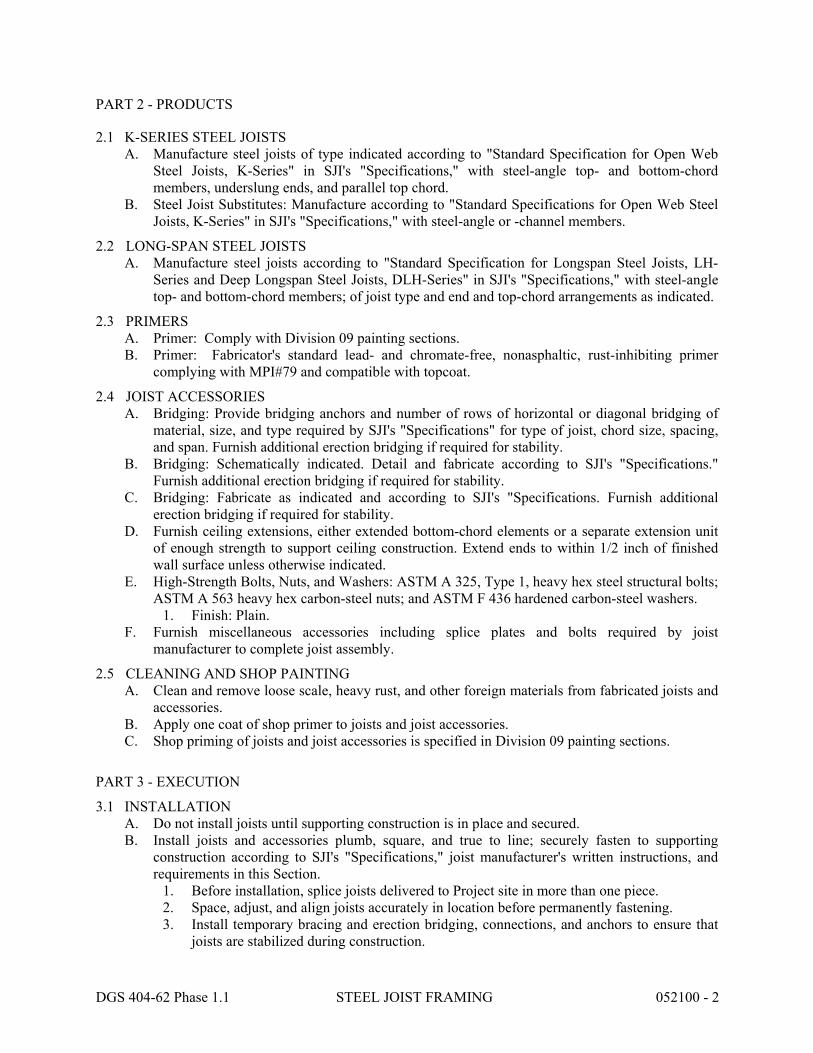
2.1 K-SERIES STEEL JOISTS A. Manufacture steel joists of type indicated according to "Standard Specification for Open Web
Steel Joists, K-Series" in SJI's "Specifications," with steel-angle top- and bottom-chord members, underslung ends, and parallel top chord.
B. Steel Joist Substitutes: Manufacture according to "Standard Specifications for Open Web Steel Joists, K-Series" in SJI's "Specifications," with steel-angle or -channel members.
2.2 LONG-SPAN STEEL JOISTS A. Manufacture steel joists according to "Standard Specification for Longspan Steel Joists, LH-
Series and Deep Longspan Steel Joists, DLH-Series" in SJI's "Specifications," with steel-angle top- and bottom-chord members; of joist type and end and top-chord arrangements as indicated.
2.3 PRIMERS A. Primer: Comply with Division 09 painting sections. B. Primer: Fabricator's standard lead- and chromate-free, nonasphaltic, rust-inhibiting primer
complying with MPI#79 and compatible with topcoat.
2.4 JOIST ACCESSORIES A. Bridging: Provide bridging anchors and number of rows of horizontal or diagonal bridging of
material, size, and type required by SJI's "Specifications" for type of joist, chord size, spacing, and span. Furnish additional erection bridging if required for stability.
B. Bridging: Schematically indicated. Detail and fabricate according to SJI's "Specifications." Furnish additional erection bridging if required for stability.
C. Bridging: Fabricate as indicated and according to SJI's "Specifications. Furnish additional erection bridging if required for stability.
D. Furnish ceiling extensions, either extended bottom-chord elements or a separate extension unit of enough strength to support ceiling construction. Extend ends to within 1/2 inch of finished wall surface unless otherwise indicated.
E. High-Strength Bolts, Nuts, and Washers: ASTM A 325, Type 1, heavy hex steel structural bolts; ASTM A 563 heavy hex carbon-steel nuts; and ASTM F 436 hardened carbon-steel washers.
1. Finish: Plain. F. Furnish miscellaneous accessories including splice plates and bolts required by joist
manufacturer to complete joist assembly.
2.5 CLEANING AND SHOP PAINTING A. Clean and remove loose scale, heavy rust, and other foreign materials from fabricated joists and
accessories. B. Apply one coat of shop primer to joists and joist accessories. C. Shop priming of joists and joist accessories is specified in Division 09 painting sections.
PART 3 - EXECUTION
3.1 INSTALLATION A. Do not install joists until supporting construction is in place and secured. B. Install joists and accessories plumb, square, and true to line; securely fasten to supporting
construction according to SJI's "Specifications," joist manufacturer's written instructions, and requirements in this Section.
1. Before installation, splice joists delivered to Project site in more than one piece. 2. Space, adjust, and align joists accurately in location before permanently fastening. 3. Install temporary bracing and erection bridging, connections, and anchors to ensure that
joists are stabilized during construction.

DGS 404-62 Phase 1.1 STEEL JOIST FRAMING 052100 - 3
C. Field weld joists to supporting steel bearing plates and framework. Coordinate welding sequence and procedure with placement of joists. Comply with AWS requirements and procedures for welding, appearance and quality of welds, and methods used in correcting welding work.
D. Bolt joists to supporting steel framework using high-strength structural bolts. Comply with RCSC's "Specification for Structural Joints Using ASTM A 325 or ASTM A 490 Bolts" for high-strength structural bolt installation and tightening requirements.
E. Install and connect bridging concurrently with joist erection, before construction loads are applied. Anchor ends of bridging lines at top and bottom chords if terminating at walls or beams.
3.2 FIELD QUALITY CONTROL A. Refer to specification sections 01400 and 01401 for requirements.
END OF SECTION 052100
SECTION 101100 - VISUAL DISPLAY UNITS
PART 1 - GENERAL
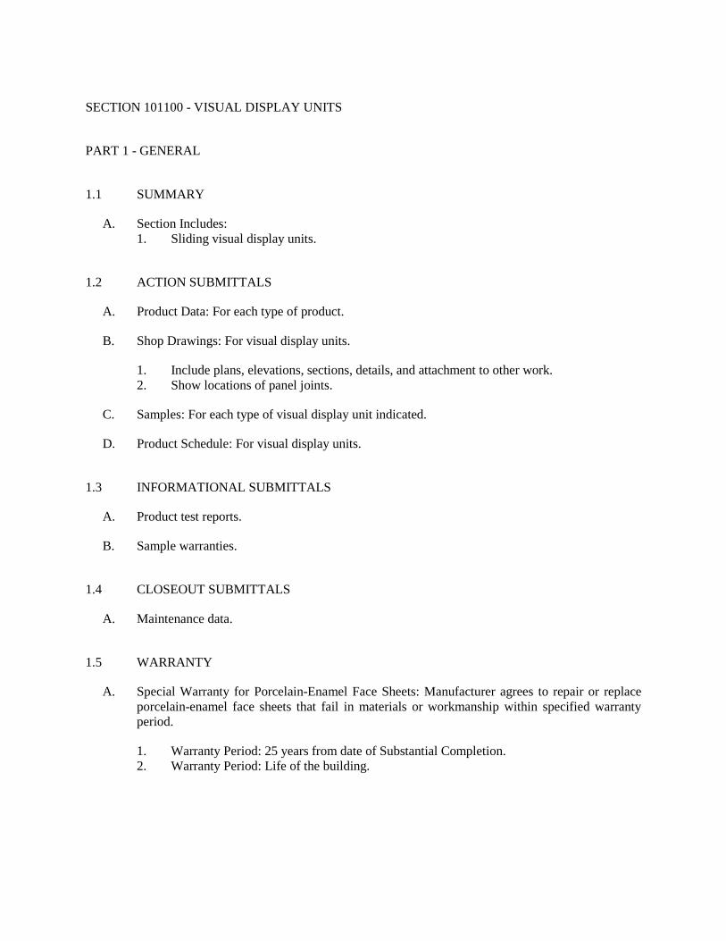
1.1 SUMMARY
A. Section Includes: 1. Sliding visual display units.
1.2 ACTION SUBMITTALS
A. Product Data: For each type of product.
B. Shop Drawings: For visual display units.
1. Include plans, elevations, sections, details, and attachment to other work. 2. Show locations of panel joints.
C. Samples: For each type of visual display unit indicated.
D. Product Schedule: For visual display units.
1.3 INFORMATIONAL SUBMITTALS
A. Product test reports.
B. Sample warranties.
1.4 CLOSEOUT SUBMITTALS
A. Maintenance data.
1.5 WARRANTY
A. Special Warranty for Porcelain-Enamel Face Sheets: Manufacturer agrees to repair or replace porcelain-enamel face sheets that fail in materials or workmanship within specified warranty period.
1. Warranty Period: 25 years from date of Substantial Completion. 2. Warranty Period: Life of the building.

PART 2 - PRODUCTS
2.1 PERFORMANCE REQUIREMENTS
A. Surface-Burning Characteristics: Comply with ASTM E 84; testing by a qualified testing agency. Identify products with appropriate markings of applicable testing agency.
1. Flame-Spread Index: 25 or less. 2. Smoke-Developed Index: 50 or less.
B. Electrical Components, Devices, and Accessories: Listed and labeled as defined in NFPA 70, by a qualified testing agency, and marked for intended location and application.
2.2 SLIDING VISUAL DISPLAY UNITS
A. Horizontal-Sliding Visual Display Units: Factory-fabricated units consisting of extruded-aluminum tubular frame, fixed rear visual display panel, aluminum-framed horizontal-sliding visual display panels, and extruded-aluminum fascia that conceals overhead sliding track; designed for recessed mounting. Provide panels that operate smoothly without vibration or chatter. 1. Basis of Design: Diversitrack by Track Technology Systems, Inc., 10053 Whitney Way,
Fishers, IN 46037, Phone: 317-841-3722, www.diversitrack.com.
2. Revise first three subparagraphs below for custom requirements to suit Project. Other configurations are available.
3. Two-Track Units: Fabricate unit with fixed rear panel covering entire rear surface. Provide one sliding panel. Panel shall slide side to side to either fully cover the flat panel display or completely uncover the flat panel display.
4. Hardware: Manufacturer's standard, extruded-aluminum overhead track and channel-shaped bottom guides; with two nylon ball-bearing carriers and two nylon rollers for each sliding panel.
5. Overall Width: As indicated on Drawings. 6. Overall Height: As indicated on Drawings.
B. Panels and Accessories:
1. Sliding Markerboard Panel: Porcelain-enamel-faced markerboard panel on kraft-paper honeycomb core designed to be rigid and to resist warpage, not less than 3/8 inch (9.5 mm) thick.
a. Color: White.
2. Accessories: Locks.
3. Aluminum Trim: Factory applied; in manufacturer's standard size and profile; with clear anodic finish.
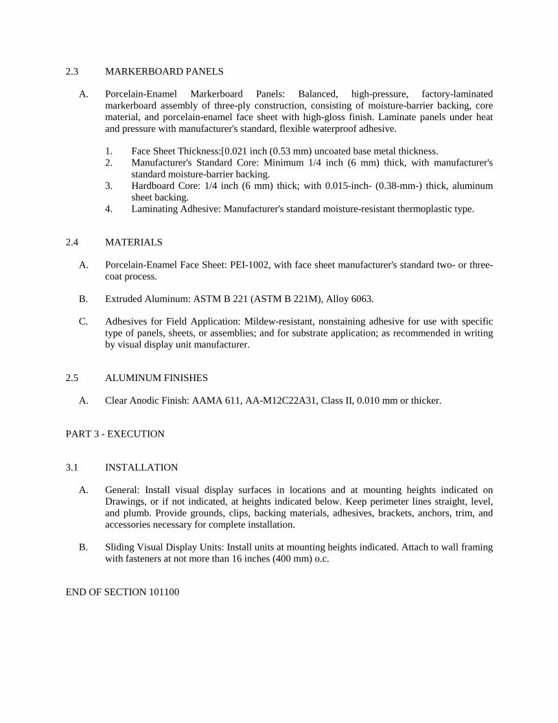
2.3 MARKERBOARD PANELS
A. Porcelain-Enamel Markerboard Panels: Balanced, high-pressure, factory-laminated markerboard assembly of three-ply construction, consisting of moisture-barrier backing, core material, and porcelain-enamel face sheet with high-gloss finish. Laminate panels under heat and pressure with manufacturer's standard, flexible waterproof adhesive.
1. Face Sheet Thickness:[0.021 inch (0.53 mm) uncoated base metal thickness. 2. Manufacturer's Standard Core: Minimum 1/4 inch (6 mm) thick, with manufacturer's
standard moisture-barrier backing. 3. Hardboard Core: 1/4 inch (6 mm) thick; with 0.015-inch- (0.38-mm-) thick, aluminum
sheet backing. 4. Laminating Adhesive: Manufacturer's standard moisture-resistant thermoplastic type.
2.4 MATERIALS
A. Porcelain-Enamel Face Sheet: PEI-1002, with face sheet manufacturer's standard two- or three-coat process.
B. Extruded Aluminum: ASTM B 221 (ASTM B 221M), Alloy 6063.
C. Adhesives for Field Application: Mildew-resistant, nonstaining adhesive for use with specific type of panels, sheets, or assemblies; and for substrate application; as recommended in writing by visual display unit manufacturer.
2.5 ALUMINUM FINISHES
A. Clear Anodic Finish: AAMA 611, AA-M12C22A31, Class II, 0.010 mm or thicker.
PART 3 - EXECUTION
3.1 INSTALLATION
A. General: Install visual display surfaces in locations and at mounting heights indicated on Drawings, or if not indicated, at heights indicated below. Keep perimeter lines straight, level, and plumb. Provide grounds, clips, backing materials, adhesives, brackets, anchors, trim, and accessories necessary for complete installation.
B. Sliding Visual Display Units: Install units at mounting heights indicated. Attach to wall framing with fasteners at not more than 16 inches (400 mm) o.c.
END OF SECTION 101100

33
44
5
6
7
8
9
10
BA
202
201
200
3.3
4.44.4
7.6
8.4
Aa
4.6
EX 6" SAN
EX SAN
EX 3"
SAN
EX 4"
SAN
EX 4"
SAN
EX S
AN
EX S
AN
EX 2"EX 1 1/2"
EX 1/2"
EX 2"
EX 1 1/2"
EX 1/2"
EX HOSEBIBB
EX 4"
EX 6"
EX 4"
EX 3"
EX 4"
EX 3"
EX 6" RWC
EX 6" RWC
EX 6" ST
REMOVE EXISTING GASMETER ANDASSOCOIATED PIPING
EXISTING HOSEBIBB
REMOVE EXISTINGFIRE SERVICEENTRANCE
REMOVE EXISTINGDOMESTIC WATERSERVICE ENTRANCE
REMOVE EX 6"REMOVE EX 4"
REMOVE EXISTINGHOSE BIBB
EX FCO
EX FCO
EX FCO
EX FCO
EX FCO
EX FCO
EX FCO
EX FCO
EX STEAMHEATEXCHANGER
EX 8"
EX 6"EX 6" RWC EX
6" S
TEX
6" S
T
EX FD
EX FD
EX FD
EX FD
REMOVE EXISTINGSTORM PIPING
SEE SITE PLAN FORGAS UTILITY WORK
EX 2"EX 1 1/2"
EX 1/2"
REMOVE EXISTING SHOWERFIXTURE IN ITS ENTIRETYINCLUDING CW & HW PIPING
REMOVE EXISTINGFLOOR DRAINS AND CAPLEVEL WITH THE FLOOR
EX FCO
REMOVE EXISTING SHOWERFIXTURE IN ITS ENTIRETYINCLUDING CW & HW PIPING
SCALE:DEMOLITION - STUDENT REC
1/8" = 1'-0"1DEMOLITION - STUDENT REC
ELP
P8.01
1/8"=1'-0"
HLH
COMMONWEALTH OF PENNSYLVANIA
DEPARTMENT OF GENERAL SERVICES
HARRISBURG, PENNSYLVANIA
PROJECT NO. D.G.S. 404-62 PHASE 1
DRAWN BY
CHECKED BY SCALE
DATE DRAWING NO.
Renovation and Expansion of Tippin Gymnasium
Clarion University, Clarion,
Clarion County, Pennsylvania
Consultant's Signature Date
REVISIONS
PARTNERSHIP Joint VentureGUNDDLA /FOSTER PLAZA 9, SUITE 200
750 HOLIDAY DRIVE
PITTSBURGH, PA 15220
Proj. No: 12-078
F:\Lo
ftus L
LC P
rojec
t File
s\_20
12\12
-078
DLA
- Tip
pin G
ynas
ium -
Clar
ion\b.
Dra
wing
s\Plum
b\P8.0
1 PLU
MBIN
G DE
MOLIT
ION
- STU
DENT
REC
.dwg
4/19/2
017 4
:03 P
M
IF BAR IS NOT ONE (1) INCH LONG,ADJUST SCALE ACCORDINGLY
0 1
BAR IS ONE (1) INCH LONGON ORGINAL DRAWING:
VERIFY SCALE
11-29-2016
DATEDESCRIPTIONNO.
11-29-2016
1
4/18/2017ADDENDUM #71

8.8
7.8
6.8
5.8
6.4
8.1
5.2
10.2
N
N
M.8
M.8
M.5
M.5
M.3
M.3
4.6
AA
9.3
8.3
7.3
6.3
5.3
J
J
K
K
L
L
M
M
Aa
AyAb
1.3
8.4
7.6
4.4 4.4
3.3
2.1
200
201
202
100
A
A
B
B
10
9
8
7
6
5
4 4
3 3
2 2
1 1
EX 6" SAN
EX SAN
EX 3"
SAN
EX 4"
SAN
EX 4"
SAN
EX S
AN
EX S
AN
EX 4"
EX 6"
EX 4"
EX 3"
EX 4"
EX 3"
EX 6" RWC
EX 6" ST
SAN
SAN
SAN
SAN
EX FCO
EX FCO
EX FCO
EX FCO
EX FCO
EX FCO
EX FCO
EX FCOEX 8"
EX 6"
CONNECT TO EXISTINGSTORM PIPING
EX 6" RWC EX 6"
ST
EX 6"
ST
8"
6"
6"
6"
6"
ST
4" V UP
SAN
SAN4"
4"
4"
4" W UP FOR CONNECTION TO KITCHENETTE
4" W UP TO FCO-1
GAS UP TO METER
4"4"
SEE SITE PLAN FORCONTINUATION
4"
4"
4" V UP
6"
4"
4" W UP TO BACKWASHCATCH BASIN STARTINGINV ELEV (-5.16'±)
INVERT ELEV (-6.20'±)
SLOP
E @
1/8"
/FT
SLOP
E @
1/8"
/FT
SLOP
E @
1/8"
/FT
SLOPE @ 1/8"/FT
TO 5'-0" BY PC
BY SITECONTRACTOR
DCW
F
BY P
C5'-
0"
6" FIRE3" DOMESTICCOLD WATER
CONNECT TO EXISTINGGAS LINE VERIFY SIZEAND LOCATION
INVERT ELEV(-1.93'±)
SAN4" W UP TO FCO-1 4"
SLOPE @ 1/8"/FT
4" 4"
4" W UP TO DD 4" W UP TO DD
4"
4" W UPTO DD
4" W UP TO DD
4" V UP
4" W UPTO FD
4" W UPTO FD
4" W UPTO FD 4" W UP
TO FD
4" W UPTO FD
4" W UPTO FD
4" W UPTO FD
4" W UPTO FD
2" W UPTO SHOWER
2" W UPTO SHOWER
4" W UPTO WC
4" W UPTO WC
1 1/2" W UPTO LAV
2" W UPTO SHOWER
2" W UPTO SHOWER
4" V UP
2" V UP
3" W UPTO MR
2" W UPTO SHOWER
4" W UPTO FD
2" V UP
4" W UPTO WC
8" S
T
4" W UPTO FD
EX FCO
SCALE:STUDENT REC - FOUNDATION PLAN
1/8" = 1'-0" (ELEV 1469'-0")1STUDENT REC - FOUNDATION PLAN
ELP
P8.02
1/8"=1'-0"
HLH
COMMONWEALTH OF PENNSYLVANIA
DEPARTMENT OF GENERAL SERVICES
HARRISBURG, PENNSYLVANIA
PROJECT NO. D.G.S. 404-62 PHASE 1
DRAWN BY
CHECKED BY SCALE
DATE DRAWING NO.
Renovation and Expansion of Tippin Gymnasium
Clarion University, Clarion,
Clarion County, Pennsylvania
Consultant's Signature Date
REVISIONS
PARTNERSHIP Joint VentureGUNDDLA /FOSTER PLAZA 9, SUITE 200
750 HOLIDAY DRIVE
PITTSBURGH, PA 15220
Proj. No: 12-078
F:\Lo
ftus L
LC P
rojec
t File
s\_20
12\12
-078
DLA
- Tip
pin G
ynas
ium -
Clar
ion\b.
Dra
wing
s\Plum
b\P8.0
2 PLU
MBIN
G ST
UDEN
T RE
C - F
OUND
ATIO
N PL
AN.dw
g4/1
9/201
7 4:17
PM
IF BAR IS NOT ONE (1) INCH LONG,ADJUST SCALE ACCORDINGLY
0 1
BAR IS ONE (1) INCH LONGON ORGINAL DRAWING:
VERIFY SCALE
11-29-2016
DATEDESCRIPTIONNO.
11-29-2016
1
4/18/2017ADDENDUM #71

8.8
7.8
6.8
5.8
6.4
8.1
5.2
10.2
N
N
M.8
M.8
M.5
M.5
M.3
M.3
4.6
AA
9.3
8.3
7.3
6.3
5.3
J
J
K
K
L
L
M
M
Aa
AyAb
1.3
8.4
7.6
4.4 4.4
3.3
2.1
200
201
202
100
A
A
B
B
10
9
8
7
6
5
4 4
3 3
2 2
1 1
EX 2"EX 1 1/2"
EX 1/2"
EX 2"
EX 1 1/2"
EX 1/2"
EX HOSEBIBB EX 6" RWC
EX 6" RWC
FCO
EXISTING HOSEBIBB
EX FCOEX FCO
EX FCO
EX FCO
EX FCO
EX STEAMHEATEXCHANGER
3" DOMESTIC WATERSERVICE ENTRANCE
6" FIRE DN
CONNECT TO EXISTINGDOMESTIC COLDWATER PIPING
3"
3"
3"
EX 6" RWC
EX FD
EX FD
EX FD
EX FD
2"
1 1/4"
1/2"
1 1/2"
3/4"
1/2"
3"
3" CAPPED FORCONNECTION BY POOLEQUIPMENTMANUFACTURER,COORDINATE
FD-2
FD-2
FD-2
FD-2
FD-1
FD-1SH-2 SH-2 SH-2 SH-2
SH-2
SH-2
SH-2SH-2
SH-2SH-2
FD-1WC-1
WC-2
L-1
WC-2
MR-1
FD-1
CONNECT TO EXISTINGDOMESTIC COLD, HOT& HWR PIPING
DD-3
DD-3
4" VENT DN
4" VTR
4" VTR
4" VTR
FCO-1
GENERATOR
ACCU-3
COOLINGTOWER
GAS METER
TWC-14
TWC-15
1"11/4"
1"11/4"1 1/4"
1"
FCO-1
FD-2
FD-2
2"
WCO-1
SH-3
3/4"
3/4"3/4" CW DN HB-2
3/4" CW DN HB-2
3/4"3/4"
1/2"
11/2"
S-4
EWC-1
1/2" CW DN
4" VTR
1 1/2"
1/2"
FCO-1
DD-2 DD-2 DD-2
DD-3
4"
DD-3
DD-3
DD-3 DD-3
4" SAN DN
4" V DN
4" V DN
4" VENT DN
4" VENT DN
EX 2"EX 1 1/2"
EX 1/2"
EX FCO
FD-1FD-1
SCALE:STUDENT REC - GROUND LEVEL
1/8" = 1'-0"1STUDENT REC - GROUND LEVEL
ELP
P8.03
1/8"=1'-0"
HLH
COMMONWEALTH OF PENNSYLVANIA
DEPARTMENT OF GENERAL SERVICES
HARRISBURG, PENNSYLVANIA
PROJECT NO. D.G.S. 404-62 PHASE 1
DRAWN BY
CHECKED BY SCALE
DATE DRAWING NO.
Renovation and Expansion of Tippin Gymnasium
Clarion University, Clarion,
Clarion County, Pennsylvania
Consultant's Signature Date
REVISIONS
PARTNERSHIP Joint VentureGUNDDLA /FOSTER PLAZA 9, SUITE 200
750 HOLIDAY DRIVE
PITTSBURGH, PA 15220
Proj. No: 12-078
F:\Lo
ftus L
LC P
rojec
t File
s\_20
12\12
-078
DLA
- Tip
pin G
ynas
ium -
Clar
ion\b.
Dra
wing
s\Plum
b\P8.0
3 PLU
MBIN
G ST
UDEN
T RE
C - G
ROUN
D LE
VEL.d
wg4/1
9/201
7 4:18
PM
IF BAR IS NOT ONE (1) INCH LONG,ADJUST SCALE ACCORDINGLY
0 1
BAR IS ONE (1) INCH LONGON ORGINAL DRAWING:
VERIFY SCALE
11-29-2016
DATEDESCRIPTIONNO.
11-29-2016
1
4/18/2017ADDENDUM #71