addendum to focusing the view camera - welcome to … · that book describes a scientific method...
TRANSCRIPT

ADDENDUM 104
ADDENDUM to
FOCUSING the VIEW CAMERAby Harold M. Merklinger
World Wide Web Edition© Harold M. Merklinger, Ottawa, Canada, September 1993
& November 1995.
Notes About This Booklet
What follows began life as the 24-page ADDENDUMto the book FOCUSING the VIEW CAMERA.
That book describes a scientific method for focusing aview camera and for determining depth of field with tiltedlenses. The Addendum provides more material, including asimplified explanation of the method as well as somerefinements. The Addendum explains, for example, howdepth of field with for tilted lens is related to depth of fieldfor an un-tilted lens. This World Wide Web edition of theAddendum has been edited to eliminate the few referencesto the original book that existed in the original Addendum.
Because this is an addendum, the figures start at Fig 38,and the pages at 104. This Addendum is, however, intendedto stand on its own. It is not necessary to have a copy ofFOCUSING the VIEW CAMERA. in order to understand thecontents.
All figures are black and white line drawings; colour hasbeen avoided in order to minimize file size.

Merklinger: FOCUSING THE VIEW CAMERA105
ADDENDUM
Introduction
Since FOCUSING the VIEW CAMERA was sent to theprinter, I’ve learned a lot. Thanks to people like Phil Davis, JohnWard and Craig Bailey who contacted me with questions orseeking clarification, a few new ways to look at the view cameraproblem have emerged. I’m also quite aware that FOCUSINGthe VIEW CAMERA is not an easy read. The purpose ofpreparing this addendum is two-fold: to try to make it easier forphotographers to grasp the basics of this way to control the viewcamera, and to describe a few refinements to earlier ideas.
I’ll attempt to offer a “Getting Started” section, somethinglike computer software manuals use to introduce new users of thesoftware to its basic features. A tutorial item will examine howdepth of field for view cameras is related to placement of theplane of sharp focus, and how depth of field for view cameras isrelated to that for normal cameras. Then I’m going to reflect onwhat I wrote earlier, commenting on some of the factors I missedthe first time around. You’ll learn, for example, how the depth offield method I described as approximate can be corrected so thatit is even more accurate and convenient to use than the depth offield tables.
The sections in this addendum are as follows:Page
Section 1 Getting Started .......................................106
Section 2 Tutorial ..................................................113
Section 3 Other Ways of IllustratingDepth of Field ........................................122
Section 4 Making the ApproximateMethod Exact .........................................124
Section 5 Proving the Exact Depth ofField Result ............................................125
Section 6 Another Look at the ReciprocalHinge Rule .............................................127
Closing ...................................................128

ADDENDUM 106
1. Getting Started
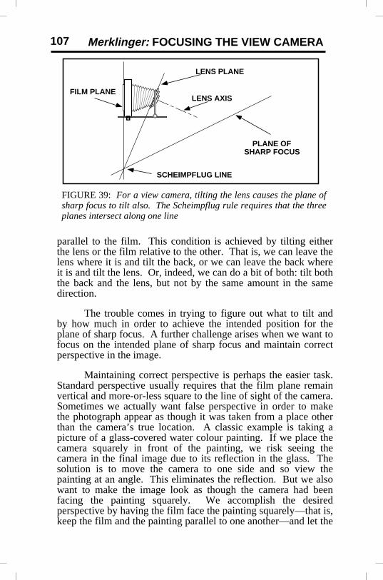
In what follows it will be assumed that the readerpossesses some basic familiarity with the view camera. Youknow what is meant by tilting and swinging the camera back andthe lens. You know that tilting the lens relative to the back—orthe back relative to the lens—causes the plane of sharp focus,that surface on which the camera is accurately focused, to moveout of parallel with the film plane. You may be aware that theScheimpflug rule states that the film plane, the lens plane and theplane of sharp focus intersect along a common line. If you don’tknow this rule, that’s OK. It’s not absolutely necessary tounderstand it, anyway.
Figure 38 shows a schematic (symbolic) diagram of anormal camera: one with the lens attached in such a way that thelens axis must stay perpendicular to the film. Figure 39 serves toindicate what happens when the lens axis (or the lens plane whichis a surface perpendicular to the lens axis) is tilted. The filmplane, the lens plane and the plane of sharp focus obey theScheimpflug rule. You need not worry about it; the laws ofphysics will make sure that it is obeyed. The general principle issimple: if we tilt one of the three planes relative to any one of theothers, the third plane will get tilted too.
In a normal camera, the camera is always focused on aplane that is parallel to the film. The view camera allows thephotographer to focus on objects arranged on a plane that is not
FIGURE 38: For a ‘normal’ camera, the film plane, lens plane andplane of sharp focus are parallel to one another.
FILM PLANELENS PLANE
PLANE OFSHARP FOCUSLENS AXIS
Merklinger: FOCUSING THE VIEW CAMERA107
parallel to the film. This condition is achieved by tilting eitherthe lens or the film relative to the other. That is, we can leave thelens where it is and tilt the back, or we can leave the back whereit is and tilt the lens. Or, indeed, we can do a bit of both: tilt boththe back and the lens, but not by the same amount in the samedirection.
The trouble comes in trying to figure out what to tilt andby how much in order to achieve the intended position for theplane of sharp focus. A further challenge arises when we want tofocus on the intended plane of sharp focus and maintain correctperspective in the image.
Maintaining correct perspective is perhaps the easier task.Standard perspective usually requires that the film plane remainvertical and more-or-less square to the line of sight of the camera.Sometimes we actually want false perspective in order to makethe photograph appear as though it was taken from a place otherthan the camera’s true location. A classic example is taking apicture of a glass-covered water colour painting. If we place thecamera squarely in front of the painting, we risk seeing thecamera in the final image due to its reflection in the glass. Thesolution is to move the camera to one side and so view thepainting at an angle. This eliminates the reflection. But we alsowant to make the image look as though the camera had beenfacing the painting squarely. We accomplish the desiredperspective by having the film face the painting squarely—that is,keep the film and the painting parallel to one another—and let the
FILM PLANE
LENS PLANE
PLANE OFSHARP FOCUS
LENS AXIS
SCHEIMPFLUG LINE
FIGURE 39: For a view camera, tilting the lens causes the plane ofsharp focus to tilt also. The Scheimpflug rule requires that the threeplanes intersect along one line

ADDENDUM 108
arrangement of the back and lens effectively squint sideways atthe painting. Figure 40 illustrates the resulting arrangement.
If achieving the desired perspective were the only problem,we could get by with lens and back shifts (plus rise and fall) only.
Let’s look now at a somewhat more complex situation.We are photographing a painting, but we want to include in theimage, not only the painting, but some of the room it is in.Specifically, the large painting is hanging in a church on a wallsome 30 feet from the camera. We also want to include a plaqueon the church floor indicating where the artist is buried. We wanta sharp image of the painting, but also a sharp image of the plateon the floor some 10 feet from the camera. To ensure both aresharp, we wish the plane of sharp focus to pass through thecenters of both the painting and the plaque. Figure 41 illustratesa side view of the problem. To keep the painting rectangular, andthe other features of the building in correct perspective, thecamera back must remain vertical and parallel to the painting.And we employ the necessary rise and/or fall to achieve thedesired composition. How do we arrange for the plane of sharpfocus to fall precisely where we want it to be?
There’s another rule that arises from the laws of optics. Icall it the hinge rule. The hinge rule will tell us the preciseamount of lens tilt needed. The hinge rule is another rule verymuch like the Scheimpflug principle, but let’s skip the details for
FILM PLANE
LENS PLANE
PLANE OFSHARP FOCUSPAINTING GLASS
FIGURE 40: The view camera can ‘squint’ sideways,maintaining the proportions of the painting. The final imagewill look as though it had been taken straight on. Taking thepicture as illustrated here avoids seeing a reflection of thecamera in the glass.

Merklinger: FOCUSING THE VIEW CAMERA109
PLANE OF SHARP FOCUS
Inscription on Floor
Painting on Wall
12 ft.
30 ft.
now. The hinge rule states that the required amount of lens tilt isrelated to only two things: the focal length of the lens, and thedistance the lens is from the plane of sharp focus measured in avery special way. We must measure how far the lens is from theplane of sharp focus along a plane through the lens but parallel tothe film. In the example at hand, the concept is quite simple.The camera back is vertical. Therefore we measure this specialdistance in a vertical direction. The special distance is quitesimply the height of the lens above the plane of sharp focus, asillustrated in Figure 42. I use the symbol J to denote this
JPLANE OF SHARP FOCUS
Inscription on Floor
Painting on Wall
12 ft.
30 ft.
PLANEPARALLEL TO
FILM,THROUGH LENS
FIGURE 41: Here the task is to adjust the plane of sharp focusso that it passes roughly through the centers of the painting andthe inscription. What amount of lens tilt will accomplish this?
FIGURE 42: The amount of lens tilt required is set by the specialdistance J and the focal length of the lens. J in this case is theheight of the lens above the plane of sharp focus.
ADDENDUM 110
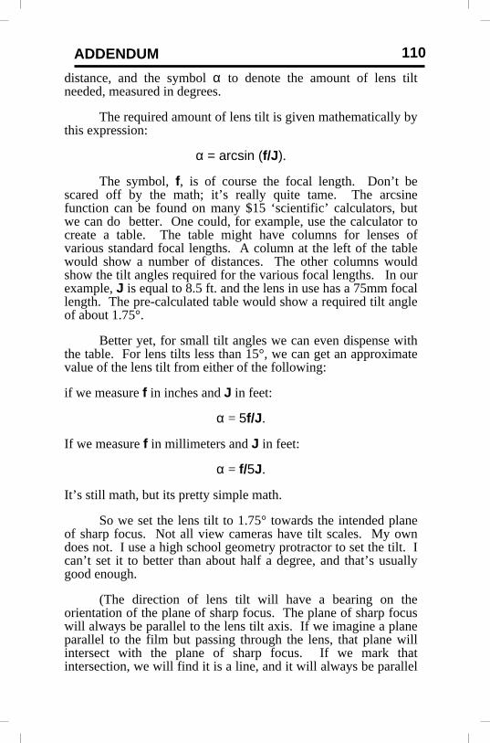
distance, and the symbol α to denote the amount of lens tiltneeded, measured in degrees.
The required amount of lens tilt is given mathematically bythis expression:
α = arcsin (f/J ).
The symbol, f, is of course the focal length. Don’t bescared off by the math; it’s really quite tame. The arcsinefunction can be found on many $15 ‘scientific’ calculators, butwe can do better. One could, for example, use the calculator tocreate a table. The table might have columns for lenses ofvarious standard focal lengths. A column at the left of the tablewould show a number of distances. The other columns wouldshow the tilt angles required for the various focal lengths. In ourexample, J is equal to 8.5 ft. and the lens in use has a 75mm focallength. The pre-calculated table would show a required tilt angleof about 1.75°.
Better yet, for small tilt angles we can even dispense withthe table. For lens tilts less than 15°, we can get an approximatevalue of the lens tilt from either of the following:
if we measure f in inches and J in feet:
α = 5f/J .
If we measure f in millimeters and J in feet:
α = f/5J.
It’s still math, but its pretty simple math.
So we set the lens tilt to 1.75° towards the intended planeof sharp focus. Not all view cameras have tilt scales. My owndoes not. I use a high school geometry protractor to set the tilt. Ican’t set it to better than about half a degree, and that’s usuallygood enough.
(The direction of lens tilt will have a bearing on theorientation of the plane of sharp focus. The plane of sharp focuswill always be parallel to the lens tilt axis. If we imagine a planeparallel to the film but passing through the lens, that plane willintersect with the plane of sharp focus. If we mark thatintersection, we will find it is a line, and it will always be parallel
Merklinger: FOCUSING THE VIEW CAMERA111
to the axis about which we moved our lens. In common viewcamera language, if we use vertical tilt only, the tilt axis ishorizontal. If we use swing only, the tilt axis is vertical. If weuse both tilt and swing, the matter gets complicated.)
In essence, the hinge rule tells us that if we move the backof the camera to and fro (without changing its angle), closer to orfarther from the lens, the plane of sharp focus must pivot on a linea distance J from the lens. In our example this pivot line is onthe plane of sharp focus directly below the lens. I call that linethe hinge line. I call it that because that line is like the pin in ahinge. The plane of sharp focus hinges on that line. As we movethe back away from the lens, the plane of sharp focus will swingup in front of the camera. If we move the camera back closer tothe lens, the plane of sharp focus will swing down, away from thelens. (It’s the Scheimpflug rule working in consort with the hingerule that causes this rotation, by the way.) So, to achieve thedesired focus in our example, we focus, using the ground glass,either on the center of the painting, or on the center of the plaque.If we have done things right, when one is in focus, the other willbe too.
That’s it; we’re done focusing.
But what about depth of field? Well, here the view camerareally has the advantage over normal cameras. Calculating viewcamera depth of field is dead simple. Plainly put, the depth offield at a distance one hyperfocal distance, H, in front of thecamera is our friend J. Like the distance J itself, this depth offield is measured in a direction parallel to the film. Either side ofthe plane of sharp focus, the depth of field is J. In this sensedepth of field is symmetrical, always—just so long as wemeasure it parallel to the film.
Can’t remember what the hyperfocal distance is? There’san easy way to remember it. The criterion for image sharpness isoften that the circle of confusion at the image should be nogreater in diameter than some fraction of the lens focal length.The number often cited is 1/1500. Well, the hyperfocal distanceis then 1500 lens aperture diameters. If our 75 mm lens is set tof/22, the hyperfocal distance will be 1500 times 75mm divided by22. That is about 5100 millimeters or 16.8 feet. Again, it mightbe useful to pre-calculate things and create a handy card showinghyperfocal distances for a variety of focal lengths and apertures.

ADDENDUM 112
It can be demonstrated that the limits of depth of field arealso planes, and that they too pass through the hinge line. Gettingback to our example, we can now sketch in the limits of depth offield. We know the depth of field at one hyperfocal distance, andwe know the limits pass through the hinge line. See Figure 43 forthe result. Looks fine: essentially everything included in ourphotograph is within the limits of depth of field.
The example just described is pretty straight forward.Unfortunately, the photographic situation will not always be quiteso easy to analyze. The film will not always be vertical, and theplane of sharp focus will not always be near-horizontal. Thebasic principles to remember are as follows:
The lens tilt, measured relative to the film plane,determines the distance from the lens to a line about which theplane of sharp focus pivots. That line, called the hinge line, willalso be parallel to the lens tilt axis.
Shortening the distance between lens and film plane causesthe plane of sharp focus to rotate (about the hinge line) awayfrom the front of the lens.
Increasing the distance between the film plane and the lenscauses the plane of sharp focus to rotate towards the front of thelens.
FIGURE 43: Depth of field for view cameras is easy. At adistance of one hyperfocal distance, H, the depth of fieldmeasured in a direction parallel to the film is simply J on eitherside of the plane of sharp focus. (Camera is is not to scale.)
8.5 ft.
PLANE OF SHARP FOCUS
Near Lim
it of D
epth of Field
Far Limit of Depth of Field
Inscription on Floor
Painting on Wall
H = 16.8 ft.
12 ft.
8.5 ft.
8.5 ft.
Merklinger: FOCUSING THE VIEW CAMERA113
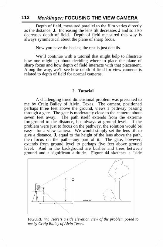
FIGURE 44: Here’s a side elevation view of the problem posed tome by Craig Bailey of Alvin Texas.
3'
GROUND
7'
5'
Depth of field, measured parallel to the film varies directlyas the distance, J. Increasing the lens tilt decreases J and so alsodecreases depth of field. Depth of field measured this way isalways symmetrical about the plane of sharp focus.
Now you have the basics; the rest is just details.
We’ll continue with a tutorial that might help to illustratehow one might go about deciding where to place the plane ofsharp focus and how depth of field interacts with that placement.Along the way, we’ll see how depth of field for view cameras isrelated to depth of field for normal cameras.
2. Tutorial
A challenging three-dimensional problem was presented tome by Craig Bailey of Alvin, Texas. The camera, positionedperhaps three feet above the ground, views a pathway passingthrough a gate. The gate is moderately close to the camera: aboutseven feet away. The path itself extends from the extremeforeground to the distance, but always at ground level. If theproblem were just to focus on the pathway, the solution would beeasy—for a view camera. We would simply set the lens tilt togive a distance, J, equal to the height of the lens above the path,then focus on the path—any part of it. The gate, however,extends from ground level to perhaps five feet above groundlevel. And in the background are bushes and trees betweenground and a significant altitude. Figure 44 sketches a “side
ADDENDUM 114
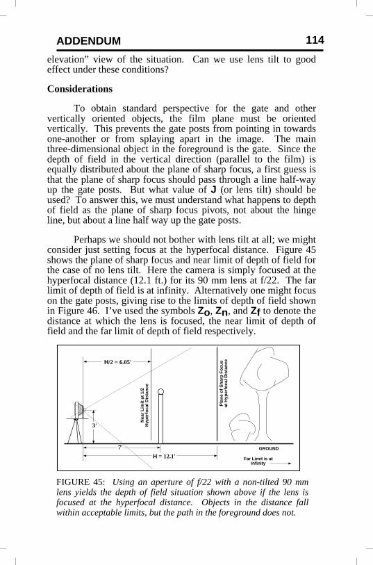
FIGURE 45: Using an aperture of f/22 with a non-tilted 90 mmlens yields the depth of field situation shown above if the lens isfocused at the hyperfocal distance. Objects in the distance fallwithin acceptable limits, but the path in the foreground does not.
3'
GROUND7'
H = 12.1'
H/2 = 6.05'
Nea
r L
imit
at
1/2
Hyp
erfo
cal D
ista
nce
Pla
ne
of
Sh
arp
Fo
cus
at H
yper
foca
l Dis
tan
ce
Far Limit is atInfinity
elevation” view of the situation. Can we use lens tilt to goodeffect under these conditions?
Considerations
To obtain standard perspective for the gate and othervertically oriented objects, the film plane must be orientedvertically. This prevents the gate posts from pointing in towardsone-another or from splaying apart in the image. The mainthree-dimensional object in the foreground is the gate. Since thedepth of field in the vertical direction (parallel to the film) isequally distributed about the plane of sharp focus, a first guess isthat the plane of sharp focus should pass through a line half-wayup the gate posts. But what value of J (or lens tilt) should beused? To answer this, we must understand what happens to depthof field as the plane of sharp focus pivots, not about the hingeline, but about a line half way up the gate posts.
Perhaps we should not bother with lens tilt at all; we mightconsider just setting focus at the hyperfocal distance. Figure 45shows the plane of sharp focus and near limit of depth of field forthe case of no lens tilt. Here the camera is simply focused at thehyperfocal distance (12.1 ft.) for its 90 mm lens at f/22. The farlimit of depth of field is at infinity. Alternatively one might focuson the gate posts, giving rise to the limits of depth of field shownin Figure 46. I’ve used the symbols Zo, Zn, and Zf to denote thedistance at which the lens is focused, the near limit of depth offield and the far limit of depth of field respectively.

Merklinger: FOCUSING THE VIEW CAMERA115
GROUNDZo = 7'Zf = 16.6'
Zn = 4.4'
Near LimitFar Limit
Plane of Sharp Focus
FIGURE 47: Tilting the lens forward by 3.3° or 5.6° yields thedepth of field limits indicated by the solid and dashed linesrespectively. The aperture is f/22. Note that increasing the lens tiltdecreases depth of field.
3'
GROUND
3'
3'
5'
5'
5'
H
FIGURE 46: Using an aperture of f/22 but focusing on the gateposts yields too little depth of field at near and far distances.
If we focus at the hyperfocal distance, the gate is withinthe established limits, but not the path in the foreground. If wefocus on the gate posts, the path is sharpened but the nearest bitsof it will still not be quite be as sharp as desired. And anythingbeyond the tree shown will be noticeably out of focus.
Let’s reconsider tilting the lens. Using the principlesillustrated in Figure 43, we can sketch the limits of depth of fieldfor a number of candidate tilted-lens situations. Two suchpossibilities are shown in Figure 47.

ADDENDUM 116
Figure 47 clearly illustrates that if the distance J is reducedfrom 5 feet to 3 feet (by increasing lens tilt), the region ofacceptable definition—the space between the near and far limitsof depth of field—shrinks noticeably. To maximize depth offield, one must minimize lens tilt. Yet tilting the lens can still bevaluable for sharpening particular regions, such as theforeground.
As the sharp-eyed may have observed, Figures 46 and 47are related. The place where the two near limits of depth of fieldcross in Figure 47 corresponds to the near limit of depth of fieldin Figure 46. And the same is true for the far limits.Furthermore, these two points of intersection, and the spot wherethe plane of sharp focus pivots, all lie along a straight linethrough the lens. This is not an accident. When the plane ofsharp focus is rotated about a fixed point in the object field—byboth tilting the lens and adjusting the lens-to-film distance—thenear and far limits of depth of field, along a ray through that fixedpoint, cannot change significantly. The principle at work here isthat depth of field is related only to the focal length, the aperture,the allowable circle of confusion diameter, and the distance atwhich the lens is focused. The depth of field, along a ray fromthe lens to a fixed point constrained to be in focus, cannot changejust because the lens is tilted.
In the problem at hand, we choose to hold focus on a pointhalf-way up the gate post. This ensures that both ends of the postwill be acceptably and equally sharp.
The procedure for plotting depth of field is simple. Firstwe select the point in the object space where we want the plane ofsharp focus to pivot. After any camera adjustments we willalways focus again on this spot. Lets call this spot “point P”.Then we draw (or imagine in our minds) the near and far limits ofdepth of field using classical techniques for untilted lenses. Forthis purpose the camera is presumed to be focused at a distanceequal to the lens-to-pivot point distance (measured in a directionperpendicular to the film plane). Then we draw, or imagine, a rayfrom the lens to point P and beyond. Where this ray intersectsthe near and far limits of depth of field indicates the pivot pointsfor these planes. We’ll call these pivot points “point C” for thenear or close limit of depth of field, and “point F” for the far limitof depth of field.
But we also know that, for a tilted lens, the near and farlimits of depth of field must pass through the hinge line. These

Merklinger: FOCUSING THE VIEW CAMERA117
facts tell us everything we need to know. In our drawing, thenear limit of depth of field extends from the hinge line to point Cand beyond. Similarly, the far limit of depth of field extendsfrom the hinge line through point F. As we adjust lens tilt,always readjusting the lens-to-film distance to keep the plane ofsharp focus passing through point P, the hinge line moves alongthe Parallel-to-Film Lens Plane. Figure 48 illustrates the depth offield limits for a J distance of 7.5 feet and for f/22. With thisset-up the foreground and gate post should be in focus, but thebase of the tree will not be. But, as a first try, we’re not far off.
(Before proceeding further, one might note that as lens tiltis adjusted towards zero, the distance J goes to infinity, and thelimits of depth of field become parallel to the film plane. Thusthe approximate method described here for view cameras is quitein accord with the traditional theory for non-tilted lenses.)
The problem now is to refine the positions of the hinge lineand the points C, P and F to best achieve our goal.
A Solution
Applying this knowledge to the problem of the gate posts,we can make the following statements. Point P should be
FIGURE 48: Using J equal to 7.5 feet (2.3° lens tilt) and f/22solves the foreground problem, but falls short of giving the desiredresult for objects in the distance. The base of the tree is outside thepermissible limits. The points C and F are at the limits of depth offield for a non-tilted lens focused on point P.
GROUND
P
C
F
Near Limit
Far Limit
Plane of Sharp Focus
N = 22J = 7.5'
Par
alle
l-to
-Film
Len
s P
lan
e

ADDENDUM 118
half-way up the gate posts, as noted earlier. Now we have justtwo things left to determine. We must choose an f-number andwe must choose the lens tilt. The lens tilt is determined by thelens-to-hinge line distance, J. Point C must be such that the nearlimit of depth of field clears the tops of the gate posts. The hingeline will probably need to be somewhere near ground level. Itcan be below ground level provided the near limit of depth offield rises above the ground where the ground first comes into thecamera’s view.
The next step is to draw the near and far limits of depth offield for a lens focused at a distance of 7 feet, but for severalapertures. We can do this using standard depth of field tables, orformulae. If we use Z to denote distance in front of the lens,measured in a direction perpendicular to the film plane, theappropriate formulae are, for the near limit:
Zn = ZoH/(Zo + H)
and for the far limit:
Zf = ZoH/(H - Zo).
H denotes the hyperfocal distance for whatever criteria wechoose, while Zo indicates the distance to the selected “point P”.In this example Zo is 7 feet. For a 90 mm lens on a 4 by 5camera, we’ll assume the hyperfocal distance is equal to 900 lensaperture diameters. This corresponds to a circle of confusiondiameter equal to 0.1 millimeters or 1/1500 of the formatdiagonal. Figure 49 shows the positions of the limits socalculated, marked along the line from lens to point P, for variousapertures. Table 1 provides the numbers appropriate to theproblem at hand.
A line from the top of the gate post, through the nearest bitof ground that can be seen by the camera, indicates that thedistance J should be no greater than 8.4 feet. If J is greater than8.4 feet, the near ground and the top of the post cannot both be inacceptable focus. The construction also indicates that an f-stop abit smaller than f/11 could be used to solve the foregroundproblem. But, as shown in the figure, f/11 leaves things in thedistance much outside the far limit of depth of field. In order forobjects in the extreme distance at ground level to be sharp, thehinge line must be at the same level as, or above, the appropriatepoint F for the aperture chosen. This ensures the far limit ofdepth of field will slope downwards away from the camera.

Merklinger: FOCUSING THE VIEW CAMERA119
TABLE 1: This Table shows Hyperfocal Distances in feetfor various f-stops as well as the near and far limits ofdepth of field for a non-tilted 90 mm lens focused at 7 feet.
f-Stop H Zn Zf2.8 94.9 6.5 7.64 66.4 6.3 7.8
5.6 47.5 6.1 8.28 33.2 5.8 8.9
11 24.2 5.4 9.912 22.1 5.3 10.216 16.6 4.9 12.122 12.1 4.4 16.627 9.8 4.1 24.232 8.3 3.8 44.638 7.0 3.5 -7382.845 5.9 3.2 -37.864 4.2 2.6 -10.290 3.0 2.1 -5.1
Re-examination of Figure 48 will illustrate that even f/22 is notsufficiently small to guarantee such an outcome. Decreasing Jhelps sharpen objects in the extreme distance, but worsensmatters at, for example, the base of the tree. With the cameraposition chosen, it might appear that a very small aperture will beneeded. A higher camera position might be called upon toalleviate the problem substantially. The higher lens positionwould both raise point C and depress point F. But it also may not
FIGURE 49: We can estimate the depth of field situation for anumber of f-stops simultaneously by plotting the limits of standarddepth of field for several apertures. An aperture just a bit smallerthan f/11 is sufficient to solve the foreground problem so long as Jis at 8.4 feet. But f/11 is far short of what is needed to sharpenobjects at ground level in the distance. (Distance scale at bottomis in feet.)
GROUND
f/8
f/22
f/16
f/11
f/32
f/8 f/11 f/16
P
C
F
f/22
J = 8.4'
The f/32 limit is at44.6 feet: twice the
distance shown here.
f/45
f/64
2015105 25
ADDENDUM 120
give us the image composition desired. Let’s not sacrificecomposition.
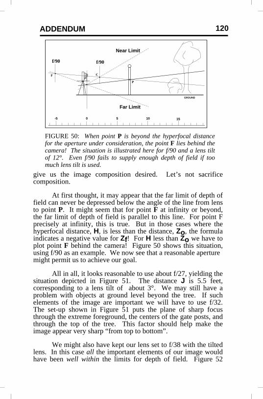
At first thought, it may appear that the far limit of depth offield can never be depressed below the angle of the line from lensto point P. It might seem that for point F at infinity or beyond,the far limit of depth of field is parallel to this line. For point Fprecisely at infinity, this is true. But in those cases where thehyperfocal distance, H, is less than the distance, Zo, the formulaindicates a negative value for Zf! For H less than Zo we have toplot point F behind the camera! Figure 50 shows this situation,using f/90 as an example. We now see that a reasonable aperturemight permit us to achieve our goal.
All in all, it looks reasonable to use about f/27, yielding thesituation depicted in Figure 51. The distance J is 5.5 feet,corresponding to a lens tilt of about 3°. We may still have aproblem with objects at ground level beyond the tree. If suchelements of the image are important we will have to use f/32.The set-up shown in Figure 51 puts the plane of sharp focusthrough the extreme foreground, the centers of the gate posts, andthrough the top of the tree. This factor should help make theimage appear very sharp “from top to bottom”.
We might also have kept our lens set to f/38 with the tiltedlens. In this case all the important elements of our image wouldhave been well within the limits for depth of field. Figure 52
FIGURE 50: When point P is beyond the hyperfocal distancefor the aperture under consideration, the point F lies behind thecamera! The situation is illustrated here for f/90 and a lens tiltof 12°. Even f/90 fails to supply enough depth of field if toomuch lens tilt is used.
GROUND
P
CF
f/90f/90
Near Limit
Far Limit
151050-5

Merklinger: FOCUSING THE VIEW CAMERA121
FIGURE 52: Another solution might have been to use f/38. Withthis aperture every element of our image is well within the depth offield limits. Without lens tilt, the near limit of depth of field wouldhave coincided with the foreground. Yes, using lens tilt gives us asharper picture!
GROUND
f/8f/22
f/16
f/11
f/32
f/8
f/11f/16
P
C
Point F is effectively at Infinity.
f/22J = 5.5'N = 38
f/45
f/64
shows this example. The penalty for using f/38 would be poorerdefinition in the sharpest parts of the image, due to diffraction.
Additional Comments
It is difficult to provide instant answers on how to bestset-up for a view camera if the important elements of the subjectbeing photographed are not naturally arranged along a plane.There are, however, relatively simple geometric principles thatcan be used to sketch the depth of field situation and help thephotographer decide what might be best for the situation at hand.One example has been examined here to illustrate these ideas.
FIGURE 51: A reasonable compromise set-up might be f/27 withJ equal to 5.5 feet (lens tilt of 3°). Objects at ground level beyondthe tree may be just a bit fuzzy, however. Using f/32 wouldprobably sharpen the image of distant objects if that werenecessary.
GROUND
f/8f/22
f/16
f/11
f/32
f/8
f/11f/16
P
C
F
f/22
J = 5.5'N = 27
f/45
f/64

ADDENDUM 122
In the example studied here, we could have used thestandard “focus at the hyperfocal distance” rule to maximizedepth of field. The result would have been that we would havehad to use about f/38 and only the gate posts would have been incritical focus. By tilting the lens 3° we have put the extremeforeground, the gate posts and the top of the tree in critical focus,and, we could open the lens by one stop. The penalty is thatobjects at ground level beyond the tree will tend to be just a bitsoft. Then again, maybe this will tend to emphasize depth in thefinal image.
In real shooting situations there is seldom a need forprecise calculations. Estimates of distance are usually goodenough to provide the insight necessary, and guide the procedureto be followed. I carry with me a table of lens tilts and Jdistances for various lenses, and a similar table of hyperfocaldistances. These guide my determination of the desired lens tilt,which is then set with the aid of a protractor. The finaladjustment is done simply by using the ground glass to set focuson the selected “point P”. I doubt that I can set the lens tilt moreaccurately than perhaps on-half of a degree. Thus I really don’tknow the value of J to better than perhaps six inches at best.What I do know, is that I could not set the camera as accurately ifI were to set the lens tilt by trial and error!
3. Other Ways of Illustrating Depth of Field
The simple relationships just described will allow us todraw a depth of field diagram for multiple f-stops, but oneorientation of the plane of sharp focus and one J distance. Anexample is shown in Figure 53. It will be seen that depth of fieldmeasured parallel to the film plane scales directly as thef-number. The depth of field measured this way for f/32 is twicethat for f/16 and so on. (The significance of lines drawn parallelto the film plane is that image magnification is constant for anyobject along such a line.)
We do not always need the same degree of definition atevery point within the “sharp” part of our image. Can wedetermine quantitatively what the circle of confusion will be forany object in the scene being photographed? The simplerelationships between depth of field and hyperfocal distance, andbetween hyperfocal distance and circle of confusion diameter,make the problem easy. Depth of field is one-third as great if we

Merklinger: FOCUSING THE VIEW CAMERA123
0.030.08 0.06 0.040.12
0.03 0.04
0.06
0.08
f = 90 mmJ = 5.5 ft.N = f/27
0.160.24
0.12
0.160.24
2520151050
+5
0
-5
-10
0
0.05
0.10
0.15
FIGURE 54: The very same drawing used for Fig. 53 can bere-labeled to map out the circle of confusion diameters (measuredat the image) for any point in the scene. The numbers representthe diameter of the circle of confusion, in millimeters, for anaperture of f/27. The vertical scale in the center has been adjustedto measure the diameter of the circle of confusion at the film. Thegray area shows the region for which the lens will be diffractionlimited.
FIGURE 53: We can show the depth of field for a number ofapertures simultaneously, as shown here. Details of the scene havebeen removed to reduce the clutter. The horizontal and verticalscales (along the edges) are in feet. Optical conditions anddistances in this diagram are the same as those used in Figure 51.The center scale shows that the vertical depth of field scalesdirectly as the f-number of the lens.
f/8f/22 f/16 f/11f/32
f/8f/11
f/16
f/22
f = 90 mmJ = 5.5 ft.a = 0.1 mm
f/45f/64
f/32
f/45f/64
2520151050
+5
0
-5
-10
0
8
16
22
32
46

ADDENDUM 124
FIGURE 55: The exact calculations for depth of fieldrequire that the depth of field at one hyperfocal distancebe fJ/A, rather than just J. The matter is of littleconsequence except in close-up photography.
J
PLANE OF SHARP FOCUS
Near Lim
it of D
epth of Field
Far Limit of Depth of FieldH
A
fJ/A
fJ/A
use one-third the original circle of confusion diameter. It is fourtimes as great for four times the circle of confusion diameter andso on. This simple scaling allows us to draw a “contour map” ofthe circle of confusion diameter for any point in the object field.In fact such a “contour map” of circle of confusion diameters fora single f-stop is just a re-labeled version of Figure 53. Anexample is illustrated in Figure 54.
We can go one step farther here by also indicating the zonefor which the lens definition will be limited by diffraction: thegray area in Figure 54. The smallest circle of confusion a lenscan produce is limited by diffraction to about N/1600 mm whereN is the f-number. That limiting diameter is about 0.017 mm atf/27 or 0.025 mm at f/38. These figures are about one-sixth toone-quarter the limit we set for depth of field purposes.
4. Making the Approximate Method Exact
The method of determining depth of field described so faris approximate. The method gives increasingly incorrect answersas the backfocus distance (lens-to-film plane distance), A,becomes significantly larger than the lens focal length, f. Thematter is easily put right with one relatively simple correction.When we do the calculations without making mathematicalapproximations, we find that the depth of field on either side ofthe plane of sharp focus is not J but rather fJ/A. And that’s allthere is to it! Figure 55 below illustrates.

Merklinger: FOCUSING THE VIEW CAMERA125
FILMPLANE
PTF PLANE
LENS PLANE
PLANE OFSHARP FOCUS
HINGE LINE
f
J
AZ = H
α
PTPSF
PLANEAT ONE
HYPERFOCALDISTANCE,PARALLEL
TO FILM
Sh
ch
h
FIGURE 56: Here’s the general scheme of things neededto determine the exact image-based depth of field from aknowledge of the object space depth of field. “PTPSF”stands for the plane which is Parallel To the Plane ofSharp Focus. The spot size diameter, Sh, is determinedin relation to its distance from the plane of sharp focus,h. The corresponding diameter of the circle of confusionis determined by the image magnification. “PTF” standsfor the Parallel-To-Film lens plane.
5. Proving the Exact Depth of Field Result
A decision I had made when I originally wroteFOCUSING the VIEW CAMERA was that I would not includeany of the mathematical proofs: I would simply state the result.But proving the exact result is so easy, that I’m going to include itin this addendum. The proof builds on the work in The INs andOUTs of FOCUS, however. If you are not familiar with myobject-based depth of field concept (or do not accept the validityof it), you may find this difficult to follow. If that is the case, justskip this section.
With reference to Figure 56, the derivation is as follows.The diameter of the disk-of-confusion, or spot size, is zero on theplane of sharp focus (PSF). Along any straight line intersectingthe PSF, the spot size, S, varies linearly. Along any line parallelto the film plane and in the object field, S will simply be:
Sh = d(h/J)
where d is the aperture diameter and h is the distance from thePSF measured along that line parallel to the film. On the film,
ADDENDUM 126
the image of that spot will be simply the magnification times Sh.That is:
ch = (A/Z) d (h/J).
In order for ch to be less than a, the maximum permitteddiameter of the circle of confusion, we require:
Adh/ZJ < a
or
h < aZJ/Ad.
Since d = f/N, and H = f2/Na, we have:
h < fZJ/AH.
For the limit of depth of field, we then replace the “less-than”sign by “equals”. That’s all there is to it. Of course one has tobelieve what’s in The INs and OUTs of FOCUS first. There’s notrigonometry required either in this derivation, or in the result!There’s still just a bit of trigonometry needed to calculate thedistance J from the lens tilt, α.
One of John Ward’s questions was: “Is H equal to f2/Na,or is H equal to f + f2/Na?” The answer is “yes”. I have foundfour slightly different definitions for hyperfocal distance. Two ofthem give the answer with the extra f in it. One gives only thef-squared term. The fourth is more complex. The definition Iused in The INs and OUTs of FOCUS, yields the simplestexpression (H = f2/Na) when I do it ‘right’. The four definitionsare: The inner limit of depth of field, measured from the lens,when the lens is focused at infinity (as in my book); same againmeasured from the film; The distance (measured from the lens)which, when focused upon, gives infinity as the far limit of depthof field; and, this last again, but measured from the film. Thedifferences are subtle and inconsequential for most purposes.
The exact result requires that we use the marked f-numberfor the aperture rather than the ‘true’ f-number, no matter howlarge A is. That’s just less calculation to do! (The depth of fieldtables in FOCUSING the VIEW CAMERA assumed one wouldalways use the ‘true’ f-number. At 1:1 image magnification, forexample, the true f-number is twice that marked on the lens.)
Merklinger: FOCUSING THE VIEW CAMERA127
6. Another Look at the Reciprocal Hinge Rule
In Chapter 2 of FOCUSING the VIEW CAMERA Iindicated I could see no immediate application for the reciprocalhinge rule. That was rash of me. While reading a 1904photography text by the British author Chapman Jones, I realizedthat it is essentially the reciprocal hinge rule that has allowed viewcamera users to use back tilt as a substitute for lens tilt.According to Chapman Jones, one should never attempt to adjustthe camera using lens tilt. He claims that will just result introuble. If one must set the lens axis out of perpendicular with thefilm, only back tilt should be considered—even though this maylead to unnatural perspective.
If one keeps the lens-to-film distance constant as one tilts alens, the plane of sharp focus moves in a complicated way that isnot easy to understand. The plane of sharp focus changes both itsrange from the camera and its angular orientation as the lens tilt isadjusted. Furthermore, the apparent movement of the plane ofsharp focus depends upon the lens-to-film distance that is set.Thus the effect of tilting the lens is difficult to anticipate. It isvery difficult to learn how to judge the right amount of lens tilt byadjusting the lens tilt directly. I refer in Chapter 8 to it being likedriving a car on ice.
Adjusting the back tilt is a much ‘friendlier’—morepredictable—operation. According to the reciprocal hinge rule,rotating the back about some fixed axis (on the film plane) merelyregulates the distance of the plane of sharp focus from the camerawithout changing its angular orientation. The angular orientationis fixed by the relative positions of the lens and the axis aboutwhich the back is being tilted. The plane of sharp focus mustremain parallel to the plane defined by the lens and the back tiltaxis.
The reciprocal hinge rule makes it easier to understandsome of the arguments over whether base tilts or axis tilts arepreferable for the camera back. The ideal, I guess, is to be able toposition the back tilt axis so as to determine the desiredorientation of the plane of sharp focus.
The difficulty I see with using back tilts is how to maintaincorrect perspective. One solution I learned from a friend—who

ADDENDUM 128
had learned it at a photography workshop—is to determine therequired amount of tilt by tilting the back, but then transfer thatamount of tilt to the lens and straighten the back. Actually thismethod is only an approximation; it breaks down under variouscircumstances, especially in the close-up range. It is possible touse a correction table to translate back tilt into the correctcorresponding lens tilt. Alternatively, one can repeat the processonce or twice to refine the setting. Each successive time, the newback angle suggests the correction needed to the tilt at the front.
Closing
I hope this addendum has accomplished a few things. Ihope the Getting Started and Tutorial sections have helped makethe methods described in FOCUSING the VIEW CAMERAsomewhat easier to understand. It should also serve to giveconfidence in using what I had thought was an approximatemethod for estimating depth of field. We now have an exactmethod that is manageable in everyday use. And finally, I hope ithas provided a bit of extra insight into the optical principlesgoverning view cameras.
I’d like to thank all those who have helped me tounderstand these things. Without their questions andencouragement, I would not have had such fun!
© Harold M. Merklinger, Ottawa, Canada, September 1993 andDartmouth, Nova Scotia, Canada, October 1998.