additions to public ground-water supplies in illinois. · of 1 l/2-in. drop pipe; reda submersible...
TRANSCRIPT


STATE OF ILLINOIS OTTO KERNER, Governor
DEPARTMENT OF REGISTRATION AND EDUCATION WILLIAM SYLVESTER WHITE, Director
SUPPLEMENT H TO
BULLETIN 40
ADDITIONS TO PUBLIC GROUND-WATER SUPPLIES
IN ILLINOIS by
ROSS HANSON
STATE WATER SURVEY DIVISION WILLIAM C. ACKERMANN, Chief
URBANA
1961
Printed by Authority of the State of Illinois

S U P P L E M E N T U
TO
BULLETIN 4 0
SUMMARY
Supplement II to Bul le t in 40 contains 299 desc r ip t i ve a r t i c l e s on public g round-wa te r sup-pl ies in I l l inois , as shown in the following table:
Of the 212 inco rpo ra t ed munic ipa l i t i e s in-cluded he re in , 178 were d e s c r i b e d in Bul le t in 40 and a r e brought up to date in this Supplement . They a r e not counted again in the State totals (Table C). The remain ing 34 a r e new suppl ies and a r e counted in the State to t a l s . The sub-d iv i s ions , public wa te r d i s t r i c t s , s an i t a ry dis-t r i c t s , and un incorpora ted p laces a r e addi t ional
to those of the same ca t egor i e s shown in Bul le t in 40 and Supplement I , as a l so a r e the seven State p a r k s .
T h e r e a r e 473 wel ls in s e r v i c e for the 299 public water s y s t e m s d e sc r i b ed in Supplement II. T h e s e wells a r e c u r r e n t l y producing 44.14 mgd. f rom th ree s o u r c e s . The s o u r c e s of water, n u m b e r of we l l s , and amount of wa te r pumped a r e shown in Table A.
Table B shows the s o u r c e s of wa te r , total n u m b e r of wells in s e r v i c e , and total pumpage for a l l public suppl ies shown in Bul le t in 40 and Sup-p l emen t s I and II.
Tab le C shows the total number of public g round-wa te r suppl ies within the Sta te , on which t he re a r e adequa te , we l l - conf i rmed data in the Su rvey ' s r e c o r d s .
TABLE A TABLE B
TABLE C
TOTAL PUBLIC GROUND-WATER SUPPLIES IN ILLINOIS

INTRODUCTION
Supplement II to Bulletin 40 completes the inventory of the State Water Survey's records of all public ground-water supplies in the State as of December 31, 1960. Included herein are:
( 1) all supplies which have been installed since Bulletin 40 (1950) and Supplement I (1958);
(2) those supplies which may have been installed before the publication of Bulletin 40, but because of scanty information in the Survey's files or in some cases a complete lackof infor-mation, were omitted from Bulletin 40;
(3) some supplies described in Bulletin 40 which have expanded their operation by finding
new sources of water, or otherwise brought about significant changes in well and water char-acteristics.
A number of towns have drilled new wells in the same field as the old well or wells and of similar construction, with no significant change in water quality. In the interest of economy these are not included herein, but the data are available upon request.
Also omitted are a number of subdivisions and unincorporated areas (possibly 150 or 175 over the State) for which there is a considerable lack of basic data. Continuing field work by the staff will fill in the missing data which then will be made available upon request to the Survey.
FORMAT
Supplement II has been organized and as-sembled in a form similar to that of Bulletin 40, with pages punched for use in either a 2 or 3-ring binder. The last date on which authoritative information was received by the Survey is shown in the upper right hand corner under the subject name.
The U. S. census population for 1960 is shown following the first mention of the name of incorporated places. For unincorporated places the population is estimated, based on the number
of services or residential units.
All elevations are in feet above mean sea level datum, unless stated otherwise.
The subdivisions and unincorporatedplaces to be found herein are listed by county on pages immediately following.
As in Bulletin 40, the public supplies are described for those State parks which have over-night lodging accommodations.
ACKNOWLEDGMENTS
Supplement II to Bulletin 40 has been compiled under the direction of William C. Ackermann, Chief of the Illinois State Water Survey.
H. F. Smith, Head of the Engineering Section, supervised the field work and the prep-aration of the manuscript.
T. E. Larson, Head of the Chemistry Section, directed, the chemical analyses and Laurel M. Henley supervised the laboratory work.
Acknowledgment is given to:
Consulting Engineers, WellDrillers, Water
Superintendents, and Municipal Officials who have been very helpful in furnishing data;
Staff members of the Illinois State Geolog-ical Survey for furnishing studies of well logs;.
The Engineering Staff of the State Water Survey for conducting production tests and col-lecting other essential data which have been made a part of this Supplement;
Mrs. J. Loreena Ivens for editing the manuscript;
Mrs. Dorothy Woller for typing and assist-ing in the composition of the manuscript.

SUBDIVISIONS, PUBLIC WATER DISTRICTS, AND UNINCORPORATED PLACES

2 - Subdivisions, Public Water Districts, and Unincorporated Places

ABBREVIATIONS AND SYMBOLS
B. H. P. brake horse power ci. cast iron cu. yd. cubic yard (s) °C degree Centigrade ° F . . . . degree Fahrenheit epm. equivalents per million ft. foot (feet) gal. gallon (s) gal. per hr gallons per hour gi. galvanized iron gpd. gallons per day gpm. gallons per minute gps. gallons per second gr. per gal grains per gallon gwi. genuine wrought iron HC. high capacity HC1 hydrochloric acid HTH. high test hypochlorite hp. horsepower hr . hour (s) id. inside diameter in. inch (es) Lab. laboratory L. S. D. land surface datum lb. pound (s) LC. low capacity MC. . medium capacity mg. million gallons mgd. million gallons per day min. minute (s) M. S. L. mean sea level mo. month (s) No. number od. outside diameter O. W. observation well ppm. parts per million psi. pounds per square inch qt. quart (s) R range rpm. revolutions per minute T township T.D.H. total dynamic head wk. week (s) wi. wrought iron % per cent

Illinois State Water Survey Bulletin 40 - Supplement II
ADAMS HEIGHTS SUBDIVISION Will County November 28, 1958
A public water supply was installed in 1952 for Adams Heights Subdivision (est. 450). Two wells are in service. The system is owned by the Adams Heights Improvement Association.
WELL NO. 1 was completed in Aug. 1952 to a depth of 204 ft. by Dreher and Schorie, Joliet, and located on Lot 18 of the subdivision, or approximately 2200 ft. S. and 150 ft. W. of the N. E. corner of Section 6, T34N, R14E. The ground surface elevation at the well is 735. The well was cased with 6-in. pipe to 125 ft.
The pumping equipment consists of 100 ft. of 1 l/2-in. drop pipe; Reda submersible pump, No. 41150, rated at 35 gpm.; 1 l/2-hp. electric motor.
WELL NO. 2 was completed in 1954 to a depth of 194 ft. and located on Lot 63, about 500
ft. northeast of Well No. 1, or approximately 925 ft. S. and 200 ft. E. of the N. W. corner of Section 5. The ground surface elevation at the well is 725. The well was cased with 124 ft. of 6-in. pipe.
The pumping equipment consists of 105 ft. of 2-in. drop pipe; Reda submersible pump, No. 413001, rated at 45 gpm.; 3-hp. electric mo-tor.
A mineral analysis of a sample (Lab. No. 148256) collected Nov. 20, 1958 showed the water to have a hardness of 29 gr. per gal., total dis-solved minerals of 489 ppm., and an iron con-tent of 1.6 ppm.
There are 160 services, all metered, and all of the subdivision is served. Pumpage is estimated to average 25, 000 gpd.
LABORATORY NO. 148256

Illinois State Water Survey Bulletin 40 - Supplement II
ADDISON DuPage County October 21, 1960
The village of Addison (6741) has four wells in service.
WELL NO. 1 was reportedly drilled in 1924 to a depth of 155 ft. and cased with 10-in. pipe from the surface to rock at 90 ft.
In July 1949 it was reported that the Key-stone piston pump had been replaced with a Cook turbine pump, Serial No. 10957, directly connect-ed to a 15-hp. U S electric motor. In June 1951 a new shaft was reportedly installed in the well. In June 1956 Well No. 1 was reported to be the sole source of supply for the village with 463 serv-ices, all metered. The pumping equipment in-cluded a Byron Jackson oil lubricated turbine pump set at 90 ft. The pump, rated at 600 gpm. at 160 ft. T.D.H., was directly connected to a 40-hp. General Electric motor. The static water level was reported to be 25 ft. below the top of the cas-ing and during pumping, the drawdown was 6 ft. There was no air line in the well.
WELL NO. 2, drilled in 1908 to a depth of 115 ft., was originally constructed for fire pro-tection. It was located on the village hall lot, about 70 ft. south of Well No. 1, or approximate-ly 1420 ft. S. and 2010 ft. W. of the N. E. corner of Section 28, T40N, R11E.
In Sept. 1950 a brief production test was made by State Water Survey personnel, at the re-quest of Village officials, to determine the value of the well as a stand-by unit. The well had, at one time, been equipped with a 30-gpm. capacity cylinder pump. The S. B. Geiger & Co., Chicago, removed the pump and found the well to be cased with 6-in. pipe to rock at a depth of 70 ft. and the hole to be 4 l/2 in. in diameter from the bottom of the casing to the bottom of the well at 91 ft. For the test a Pomona turbine pump was install-ed with the bottom of the bowls set at 70 ft. and an air line of 70 ft. length. The power was fur-nished by a 7 1/2-hp. electric motor.
Water was pumped for 2 hr. at rates accel-erated from 75 to 98 gpm. with a maximum draw-down of 7 ft. from a nonpumping water level of 41 ft. below the top of the casing. During this test the pump in Well No. 1, about 50 ft. distant, was operating at a rate of 160 gpm. Since the test pump was too small to develop the full capac-ity of the well, the test was discontinued. In June
1956 Well No. 2 was reportedly used only during periods of peak demand. The pumping equipment included a Fairbanks-Morse turbine pump, Serial No. AM2979, rated at 200 gpm. atl60ft. T.D.H., directly connected to a 10-hp. U S electric motor.
In Aug. 1957 Well No. 2 was reported to be in use daily.
WELL NO. 3 was completed by J. P. Mil-ler Artesian WellCo., Brookfield, toadepthof 221 ft. in the spring of 1956 and located on the east side of Michigan St., north of Fullerton St., or approx-imately 160 ft. N. and 1540 ft. W. of the S. E. cor-ner of Section 28. The well was cased from the surface to 78 ft. with 14-in. od. gwi. pipe and with 10-in. id. gwi. pipe from 18 in. above to 110 ft, be-low the ground surface. The annulus between the casings was filled with cement grout. Below the casings the hole was finished 13 l/4.in. in diameter to the bottom. Well No. 3 was placed in service in 1957 and was equipped with a Model 10 RM Layne and Bowler pump rated at 600 gpm. at 300 ft. T.D.
H., directly connected to a 60-hp. Louis Allis electric motor.
In a production test on July 24, 1956 water was pumped for 8 hr, at a rate of 500 gpm. with a drawdown of 104 ft. from a static water level of 14 ft. below the ground surface (elev. 665).
Analysis of a sample (Lab. No. 146504) col-lected Apr. 28, 1958, after 5min. pumping, show-ed the water in Well No. 3 to have a hardness of 24. 9 gr. per gal., total dissolved minerals of 525 ppm., and an iron content of 1.1 ppm.
Late in 1955 or early in 1956 the Pleasant View Acres Subdivision water system facilities was purchased by the village of Addison. The system included 713 services, 100% metered. The subdivision well, now designatedas village WELL NO. 4, was drilled in 1954 to a depth of 250 ft. by a Mr. Bilskey of Hinsdale. The well is located south of Addison on the north side of Winthrop, west of Westgate, or approximately 1350 ft. S. and 1050 ft. E. of the N. W. corner of Section 33. The well was cased with 10-in. id. pipe, penetrating rock at 81 ft. The pumping equipment included a Sta-Rite turbine pump, Serial No. OI3860, rated at90'gpm. against 220 ft. T.D.H., and attached to 60 ft. of 3-in. column pipe and powered by a 7 1/2-hp. U S electric motor.

2 - Addis on
A mineral analysis of a sample (Lab. No. 146505) collected Apr. 28, 1958, after 5 min. pumping, showed the water in Well No. 4 to have a hardness of 24. 5 gr. per gal. , total dissolved minerals of 495 ppm., and an iron content of 1.1 ppm.
In Oct. 1960 new pumping equipment was installed consisting of 165 ft. of 5-in. column pipe; 8-in., 13-stage Layne turbine pump, No. 40426, and rated at 375 gpm. at 300 ft. T.D.H.; 10 ft. of 6-in. suction pipe with strainer; 165 ft. of air line; 40-hp. Westinghouse electric motor.
Pumpage for Addison is reported to aver-age 375,000 gpd.
Correlated dri l ler ' s log of WELL NO. 4 fur-nished by the State Geological Survey
Strata Thickness Bottom ft. ft.
PLEISTOCENE SERIES Drift 74 74
SILURIAN SYSTEM Limestone 176 250 Shale - 250
LABORATORY NO. 146505

Illinois State Water Survey Bulletin 40 - Supplement II
ALPHA Henry County January 22, 1957
Water for the public water supply of the village of Alpha (637) is obtained from one well.
WELL NO. 1, described in Bulletin 40 as being leased from the C. B. & Q. Railroad, has not been used since about 1950 or 1951.
WELL NO. 2 was completed at the site of Test Well No. 1-50 in Jan. 1950 by Peerless Ser-vice Co., Orion. It was drilled to a depth of 1209 ft. and located near the corner of "E" and Second St. about 1 block northeast of Well No. 1, or approximately 1750 ft. S. and 650 ft. W. of the N. E. corner of Section 21, T14N, R1E. The ground elevation at the well is 800. The hole and casing record is shown in Table A.
TABLE A
Hole Record
1 6-in. from surface to 240 ft. 12-in. from 240 ft. to 433 ft. 10-in. from 433 ft. to 551 ft.
8-in. from 551 ft. to 1209 ft.
Casing Record
12-in. id. from surface to 240 ft. 10-in. id. from 240 ft. to 433 ft.
8-in. id. from surface to 551 ft.
A production test was conducted on Test Well No. 1-50 on Jan. 16, 1950 by representatives of the Driller, the State Water Survey, and the Austin Engineering Co., Consulting Engineers. For test purposes the well was equipped with an electrically driven Peerless turbine pump, rated at 100 gpm. against 400ft. T.D.H. The assembly included 350 ft. of 4-in. column pipe; 12 ft. of pump bowls in 28 stages; 20 ft. of tail pipe. The pump assembly was to be retained as the perma-nent equipment. A 350-ft. air line was in place for determining water levels.
After 4 1/2 hr. pumping at a rate of 112 gpm., the drawdown was 49 ft. from a nonpump-ing water level of 256 ft. Ten min. after pump-
ing was stopped, the water level had recovered to 260 ft.
A mineral analysis of a sample (Lab. No. 120516) collected Jan. 16, 1950, after 4 1/2 hr. pumping at 112 gpm., showed the water in Test Well No. 1-50 to have a hardness of 14. 7 gr. per gal., total dissolved minerals of 754 ppm., and an iron content of 2. 7 ppm.
Test Well No. 1-50 was then accepted by the village and designated as Well No. 2.
There are 240 services, all metered and serving 100% of the population.
Pumpage for 1956 averaged about 35, 000 gpd.
Correlated driller's log of Alpha Test Well No. 1-50, now WELL NO. 2, furnished by the State Geological Survey

2 - Alpha
LABORATORY NO. 120516

Illinois State Water Survey Bulletin 40 - Supplement II
AMBOY Lee County November 17, 1960
Two wells are available for use by the city of Amboy (2067).
WELL NO. 1, described in Bulletin 40, is not in service and may be retired.
WELL NO. 2, described in Bulletin 40, is available for service, but has been used only occasionally since Well No. 3 was constructed.
WELL NO.. 3 was completed in Mar. 1958 to a depth of 1105 ft. by Layne-Western Co., Aurora, and located about 60 ft. east of Well No. 2, about 80 ft. north of the treatment plant, or approximately 779 ft. S. and 1315 ft. W. of the N. E. corner of Section 22, T20N, R10E. The ground surface elevation at the well is 750. The well is cased with 20-in. steel pipe from the sur-face to 29 l/2 ft. and with 16-in. steel pipe from the surface to 235 ft. (cemented in), below which the hole was finished 15 l/4 in. in diameter to the bottom.
A production test was conducted on Jan. 24,
1958 by representatives of the Driller, the State Water Survey, and C. K. Willett Co., Consult-ing Engineers. After 16 hr. pumping at a rate of 644 gpm., the drawdown was 150 ft. from a non-pumping water level of 44 ft. Eight hr. after the test was stopped, the water level had returned to 44 ft.
The pumping equipment includes a Byron Jackson turbine pump, No. 351463, rated at 500 gpm. at 286 ft. T.D.H. or 350 gpm. at 140 ft. Power for pumping is from a 50 and 22-hp. var-iable speed U S electric motor.
A mineral analysis of a sample (Lab. No. 153626) collected Nov. 16, 1960 showed the water in Well No. 3 to have a hardness of 21. 6 gr. per gal., total dissolved minerals of 389 ppm., and an iron content of 2. 8 ppm.
There are approximately 540 services, 60% of whichare metered. Pumpage is reported to average 104, 177 gpd.
LABORATORY NO. 153 626

Illinois State Water Survey Bulletin 40 - Supplement II
ANTIOCH Lake County July 21, 1958
The village of Antioch (2268) has three wells in service.
The pump in WELL NO. 1 was removed in 1952 and 20 ft. of column pipe was added.
WELL NO. 2 was repaired in Nov. 1949 by C. L. Wertz, Antioch. The well was cased with 220 1/2 ft. of 10-in. pipe and 11 ft. of 6-in. John-son Everdur screen (No. 160 slot openings) to a total depth of 231 1/2 ft. to the bottom of the screen. A leaded wooden plug was installed in the bottom of the screen. Upon completion of the repairs, water was pumped at a rate of 200 gpm. with a drawdown of 70 ft. from a nonpumping water level of 45 ft. below the surface.
In Dec. 1949 a new Peerless turbine pump rated at 250 gpm., was installed in Well No. 2 and directly connected to a 20-hp. General Elec-tric motor. New column pipe was also installed.
WELL NO. 3 was completed in 1953 to a depth of 149 ft. by Layne-Western Co., Aurora, and located 500 ft. south of Ada St. and 88 ft. east of the Soo Line right-of-way, or approxi-mately 600 ft. N. and 2360 ft. W. of the S. E. corner of Section 8, T46N, R10E. The completed well was located at the site of a 6-in. test well which had been drilled to a depth of 149 ft. in Dec. 1952. The static water level in the test well was 12 ft. 8 in. below the ground surface. Well No. 3 was cased with 12-in. pipe from 10 in. above the pump house floor to 122 ft. and cement grout-ed from the surface to 40 ft. The well was of 28 by 12-in. gravel pack construction from the sur-face to 142 ft. with a 12-in. id. black steel cas-ing from 2 ft. above the surface to 122 ft. and a 12-in. id. Layne shutter screen from 122 to 142 ft. When completed water was reportedly pump-ed at a rate of 800 gpm. with a drawdown of 12 ft. from a nonpumping water level of 41 ft. below the surface.
The permanent pump assembly consists of
70 ft. of 6-in. column pipe; 10-in., 7-stage Layne turbine pump, No. 26899, rated at 400 gpm. a-gainst 235 ft. T.D.H. and having an over-all length of 6 ft. 1 in.; 10 ft. of 6-in. suction pipe; 70 ft. of air line; 40-hp. U S electric motor.
On May 29, 1958 water was being pumped at a rate of 415 gpm. with a drawdown of 7 ft. from a nonpumping water level of 45 ft. below the pump base.
Analysis of a sample (Lab. No. 146791) col-lected May 29, 1958 showed the water in Well No. 3 to have a hardness of 12 gr. per gal., total dis-solved minerals of 350 ppm., and an iron content of 0. 6 ppm.
Pumpage from May 1, 1957 to Apr. 30, 1958 averaged 177,000 gpd.
Sample study summary log of WELL NO. 3 fur-nished by the State Geological Survey

2 - Antioch
LABORATORY NO. 146791

Illinois State Water Survey Bulletin 40 - Supplement II
ARBURY HILLS SUBDIVISION Will County March 25, 1960
A public water supply was installed in 1960 for the Arbury Hills Subdivision (Futuristic Homes Inc. ), located about 2 miles east of Mokena.
WELL NO. 1 was completed to a depth of 457 ft. in Mar. 1960 by Wehling Well Works, Beecher, and located approximately 1380 ft. S. and 1306 ft. E. of the N. W. corner of Section 10, T35N, RUE. The ground surface elevation at the well is 735. The well is cased with 20-in. od. pipe from the surface to 121 ft., below which the hole was finished in limestone and shale at 19 l/4 in. in diameter to the bottom at 457 ft.
A production test was conducted on Mar.
23-25, 1960 by representatives of the Driller and the State Water Survey. After development of the well on Mar. 23-24, pumping was started on Mar. 25 and after 4 hr. pumping at 253 gpm., the drawdown was 164 ft. from a nonpumping wa-ter level of 56 ft. below the pump base.
A partial chemical analysis of a sample (Lab. No. 152064) showed the water to have a hardness of 66 gr. per gal., total dissolved min-erals of 1581 ppm., and an iron content of 0.9 ppm.
The permanent pump has not been install-ed.
LABORATORY NO. 152064

Illinois State Water Survey Bulletin 40 - Supplement II
ARCOLA Douglas County January 19, 1960
Three wells are in service for the public water supply of the city of Arcola (2273).
WELLS NO. 1 and 2, described in Bulletin 40, have been disconnected from the system.
WELLS NO. 3 and 4, described in Bulletin 40, are not in service but have not been discon-nected from the system.
WELL NO. 1-A was disconnected from the system in 1952 and is used for water table ob-servations by the Illinois State Water Survey.
WELL NO. 2-A, described in Bulletin 40, was equipped in 1955 witha newFairbanks-Morse submersible pump, rated at 170 gpm. and con-nected to a 10-hp. U S electric motor.
Well No. 2-A is in service about one week of each month and furnishes about 25% of the city demand.
WELL NO. 5 was completed in May 1955 to a depth of 106 ft. by Layne-Western Co., Kirk-wood, Mo. A number of test holes had been drilled in 1954 and Well No. 5 was constructed at the site of Test Hole No. 6-54, about 1 mile northeast of Well No. 2-A, or approximately 50 ft. N. and 2500 ft. E. of the S. W. corner of Section 34, T15N, R8E. The ground surface elevation at the well is 660.
A 30-in. hole was drilled from the surface to 106 ft. and a 12-in. casing was set from 1 1/2 ft. above the surface to 81 ft. followed by an 8-in. screen from 81 to 106 ft. Gravel was packed in the annulus between the casing and screen and the wall of the hole from 106 ft. up to 31 ft. A clay fill was placed in the annulus from 31 to 3 ft. and concrete in the upper 3 ft. to the surface.
The permanent pumping equipment was in-stalled in Aug. 1955 consisting of 70 ft. of 5-in. column pipe; 5 3/4-in., 9-stage Deming turbine pump, No. 22957, rated at 175 gpm. at 125 ft. T.D.H.; the over-all length of column pipe and pump is 76 ft. 11 1/2 in.; 7 l/2-hp. U S electric motor. A Johnston gear drive is installed for auxiliary power.
A production test was conducted onAug. 11, 1955 by representatives of the Driller, the State Water Survey, and Warren and VanPraag, Con-sulting Engineers. After 2 hr. pumping at rates of 230 to 250 gpm., the drawdown was 10. 6 ft. from a nonpumping water level of 32. 2 ft.
A partial chemical analysis of a sample (Lab. No. 138429) collected Aug. 11, 1955, after 2 hr. pumping at 245 gpm., showed the water to have a hardness of 15.1 gr. per gal., total dissolved minerals of 425 ppm., and an iron content of 4. 2 ppm.
WELL NO. 6 was completed in Dec. 1955 to a depth of 118 ft. 9 in. by Layne-Western Co. and located at the site of Test Hole No. 7-54, about 1/2 mile northeas t of town, or approximately 850 ft. S. and 50 ft. E. of the N. W. corner of Section 3, T14N, R8E. The ground surface ele-vation at the well is 668. A 30-in. hole was drilled from the surface to the bottom. A 12-in. casing and 25 ft. of 8-in. Layne No. 7 wrought steel screen were set in the hole and gravel packed similar to Well No. 5.
The pumping equipment consists of 80 ft. of 5-in. column pipe; 5 3/4-in., 9-stage Deming turbine pump, Serial No. 22957, rated at 175 gpm. against 125 ft. T.D.H.; 80 ft. of air line; 7 l/2-hp. U S electric motor.
On Dec. 30, 1955, after 5 1/4 hr. pumping at 125 gpm., the drawdown was 16.1 ft. from a nonpumping water level of 47. 8 ft. below the pump base.
A partial chemical analysis of a sample (Lab. No. 139371) collected Dec. 30, 1955, after 5 1/4 hr. pumping, showed the water to have a hardness of 13. 6 gr. per gal., total dissolved minerals of 390 ppm., and an iron content of 4.1 ppm.
Wells No. 5 and 6 furnish about 75% of the city demand.
Pumpage for the city in 1959 averaged 145,000 gpd.

2 - Arcola
LABORATORY NO. 139371

Illinois State Water Survey Bulletin 40 - Supplement II
ARLINGTON Bureau County January 26, 1957
The village of Arlington (254) has two wells in service.
WELL NO. 1 (West) was abandoned about 1951 and filled in reportedly with puddled clay. The pit, surrounding Wells No. 1 and 2 (East), has been filled in and a concrete floor laid over the fill.
WELL NO. 2 is in service, with no change in pumping equipment reported since Bulletin 40.
WELL NO. 3 was drilled to a depth of 81 ft. in 1954 by Daniel Schmidt, Mendota, and located 100 ft. N. and 150 ft. E. of the S. W. corner of the N. E. 1/4 of Section 8, T17N, RUE. The ground elevation at the well is 752. The well was originally drilled to a depth of 100 ft. and backfilled with pea gravel to 81 ft.
A 10-in. steel casing was set to a depth of 73 ft. with 10 ft. of 10-in. No. 60 slot Johnson Everdur screen (8 ft. exposed) set with the bot-tom at 83 ft. The elevation of the top of the cas-ing at the pump base was 753. 2. A production test was made on Jan. 20, 1955 and observed by representatives of the Driller, the State Water Survey, and Wallace Engineering Co., Peoria, Consulting Engineers. For the test, power was furnished from the drill rig. After 3 1/4 hr. pumping at a final rate of 100 gpm., the draw-down was 3. 6 ft. from a nonpumping water level of 29. 3 ft. below the top of the casing. Seven min. after pumping was stopped, the water level
had recovered to 29. 6 ft. For 1 hr. during the test, Well No. 2 was pumped with no decrease in the rate (115 gpm. ) in Well No. 3.
Correlated driller's log of WELL NO. 3 furnish-ed by the State Geological Survey
Analysis of a sample (Lab. No. 136762) col-lected Jan. 20, 1955, after 1 1/2 hr. pumping, showed the water in Well No. 3 to have a hard-ness of 20. 3 gr. per gal., total dissolved min-erals of 372 ppm., and an iron content of 1 ppm.
The permanent pump assembly consists of 60 ft. of 3-in. column pipe; 5 2/16-in. od., 7-stage Jacuzzi water lubricated turbine pump, No. SL6-6, rated at 90 gpm. at 40 lb. head; 60 ft. of 1/4-in. plastic air line; 5-hp. electric motor.
Pumpage is reported to average 9950 gpd.
LABORATORY NO. 136762

Illinois State Water Survey Bulletin 40 - Supplement II
ARLINGTON HEIGHTS Cook County August 19, 1958
The village of Arlington Heights (2,7,878) has four wells in service.
WELL NO. 1 was abandoned and reportedly-filled with sand and concrete in July 1956.
WELL NO. 2, located at the corner of Chestnut and Hawthorne St., was rehabilitated in June 1956 by L. Cliff Neely, Batavia. A total of 810 qt. of nitrogel was exploded between 1220 and 1310 ft. depth. A cement grout had been plac-ed, prior to 1955, in the annulus outside the 10-in. casing to the bottom of the 10-in. casing at 455 ft. The casing and hole record is shown in Table A.
TABLE A
Hole Record
12-in. from surface to 455 ft. 10-in. from 455 ft. to 1345 ft. (bottom)
Casing Record
12-in. from surface to 1 6 1 ft. 10-in. from surface to 455 ft. 8-in. liner (479 ft.) from 571 to 1050 ft.
The pumping equipment includes 550 ft. 7-in. column pipe; 7-in., 14-stage Peerless tur-bine pump, 14 ft. long and rated at 700 gpm.; 20 ft. of 6-in. suction pipe with strainer; 550 ft. of air line; 100-hp. U S electric motor.
In Mar. 1958 a State Department of Public Health report stated that Well No. 2 was "on stand-by status at present."
WELL NO. 3 was abandoned in July 1945.
WELL NO. 4, located at Wing and Kennicott St., has been cleaned out and reworked. The well was rehabilitated in the fall of 1955 by L. Cliff Neely, and is reportedly cased with 16-in. od. grouted pipe to 142. 5 ft.; 14-in. od. pipe from the surface to 162. 5 ft.; the old liner was removed and replaced with a new 10-in. liner to 350 ft. depth.
After the well was reworked the following pumping equipment was installed: 505 ft. of col-umn pipe; 10-in., 22-stage Peerless turbine pump rated at 780 gpm.; 200-hp. Westinghouse
electric motor.
The nonpumping water level was reported to be 350 ft. with a drawdown of 110 ft.
Well No. 4 is in service.
WELL NO. 5, located at Douglas St. and Foundry Road, was rehabilitated in the. spring of 1956 by L. Cliff Neely. The well is reportedly cased with 24-in. od. cement grouted pipe to 108 ft.; 422 ft. of 14-in. od. cement grouted liner pipe from the surface; from 422 to 900 ft. is a 13 1/4-in. hole; from 900 to 1000 ft. is a new 10-in. liner which was pulled and replaced at time of rehabilitation. From 1000 ft. to 1525 ft. the hole is 2 in. in diameter.
After the rehabilitation work the following pumping equipment was installed: 550 ft. of 10-in. column pipe; 12-in., 9-stage Byron Jackson turbine pump rated at 1050 gpm.; 20 ft. of 8-in. suction pipe with strainer; 550 ft. of 1/4-in. stain-less steel air line; 250-hp. U S electric motor. An Aurora centrifugal booster pump is directly connected to the discharge line. It has a capacity of 800 gpm. against 150 ft. T.D.H. and is directly connected to a 40-hp. U S electric motor.
A production test was conducted on Apr. 24, 1956 by representatives of the Drilling Contractor, Consoer and Townsend, Consulting Engineers, and the State Water Survey. After 10 1/2 hr. pumping at 1056 gpm., the drawdown was 74 ft. from a nonpumping water level of 334 ft. below the ground level. Ten min. after pumping was stopped, the water level had recovered to 361 ft.
Well No. 5 is in service.
WELL NO. 6 was drilled to a depth of 1553 ft. in 1952 by R. E. Milaeger Well Drilling Co., Milwaukee, Wis. The well is located near the corner of Wing and Ridge St., or approximately 1087 ft. N. and 1532 ft, W. of the S. E. corner of Section 30, T42N, R11E. The ground elevation at this location is 707.
The well was cased from the surface to 435 ft. with 18-in. od. pipe which was grouted in. The hole was 15 1/4 in. in diameter from top to bottom. A 12-in. od. liner was placed from 922 to 1140 ft. The well was reportedly shot with 400 lb. of 100% nitroglycerine atfour locations with the bottom of the shots at 1490, 1280, 1230 and 1180 ft.

2 - Arlington Heights
depths. A large amount of sand was removedfrom the well after shooting.
On Jan. 20-21, 1953 a production test was conducted by representatives of the Drilling Contractor, Consoer and Townsend, Consulting Engineers, and the State Water Survey. After 5 hr. pumping at a rate of 1100 gpm., the draw-down was 131 ft. from a nonpumping water level of 278 ft. below the ground level. One hr. after pumping was stopped, the water level had recov-ered to 312 ft.
On Jan. 23, 1953, after the pump was re-moved, the well was sounded and found to have filled with sand to a depth of 1155 ft. The static water level was found to be 300 ft. below the sur-face.
After about one month spent in removing the sand, a second production test was conducted on Feb. 25-26, 1953. After about 14 l/2 hr. pumping at a rate of 1120 gpm., the drawdown was 98 ft. from a nonpumping water level of 227 ft. But after the pump was removed, sand was found to have filled in again to a depth of 1155 ft. The sand was once more removed, but this time it was found that a section of about 180 ft. of the lower wall hole was not filled with sand. By May 1 the sand was cleaned out to 1530 ft.
On May 4-5, 1953 a third production test was conducted. After 15 1/2 hr. pumping at a rate of 1200 gpm., the drawdown was 97 ft. from a nonpumping water level of 290 ft. On removal of the pump, the sand was found to have filled in to 1475 ft. depth. The pumping equipment in-stalled about May 1953 included a 10-in., 9-stage Layne and Bowler turbine pump set at 520 ft. and rated at 1000 gpm. against a T.D.H. of 575 ft.; 250-hp. U S electric motor.
Analysis of a sample (Lab. No. 146375) collected Apr. 17, 1958, after 6 hr. pumping at 1250 gpm., showed the water in "Well No. 6 to have a hardness of 15.6 gr. per gal., total dis-solved minerals of 385 ppm., and an iron content of 0. 2 ppm.
Well No. 6 is in service.
WELL NO. 7 was completed to a depth of 1553 ft. in May 1958 by L. Cliff Neely and lo-cated on Frederick St., 300 ft. east of Hickory
St., or approximately 600 ft. S. and 2050 ft. W. of the N. E. corner of Section 29. The ground elevation is 692. 5. The well hole and casing record is shown in Table B.
TABLE B
Hole Record
25 1/4-in. from 0 to 433. 5 ft. 1 9 1/4-in. from 433. 5 to 1112. 5 ft. 1 5 1/4-in. from 1112.5 to bottom
Casing Record
26-in. od. steel pipe from 0 to 147. 5 ft. 20-in. od. steel pipe from 0 to 433. 5 ft. The 20-in. casing was cemented in by Holland Well Service, using 175barrels.
A production test was conducted on Apr. 17-18, 1958. For test purposes the well was equipped with a 12-in., 8-stage pump set at 555 ft. An air line, 555 ft. long, was installed. After 21 hr. pumping at a rate of 1114 gpm., the discharge rate suddenly dropped to 617 gpm. While pump-ing at 1114 gpm., the drawdown was 173 ft. from a nonpumping water level of 300 ft. (255 ft. above the bowls) below the top of the casing. Due to the pump trouble the test was terminated. Fol-lowing the production test "the well was shot with 44251b. of Nitro(Jell Form) requiring 2684 hours of clean-out time and recovering a tremendous amount of sand. "
On June 9-10, 1958 a second production test was conducted. After 20 hr. pumping at a rate of 1534 gpm., the drawdown was 130 ft. from a nonpumping water level of 365 ft. below the pump base (at the end of 100 hr. quiet period).
The permanent pumping equipment is on order and is presently being manufactured. The installation will include 600 ft. of 13 3/8-in. col-umn pipe; Byron Jackson submersible pump rated at 1200 gpm. against 600 ft. T.D.H. at 1750 rpm.; 600 ft. of air line; 250-hp. Byron Jackson electric motor.
It is expected that the well will be in ser-vice Oct. 31, 1958.
Pumpage for Arlington Heights is reported to average 1 mgd.

Illinois State Water Survey Bulletin 40 - Supplement II
ASHMORE Coles County November 25, 1960
A public water supply was installed in 1955 for the village of Ashmore (447).
WELL NO. 1 was completed in May 1955 to a depth of 42 ft. by Henry Holkenbrink, Effing-ham, and located at the south end of town on Third St., or approximately 350 ft. S. and 700 ft. E. of the N. W. corner of Section 6, T12N, R11E. The ground surface elevation at the well is 685. A 24-in. hole was drilled from the sur-face to the bottom of the well and cased with 24-in. pipe from 1 ft. above to 25.7 ft. below the ground surface and with 10-in. pipe from 2 ft. above to 31.5 ft. below the surface, followed by 10 ft. of 10-in. screen, having No. 80 slot open-ings. The well was gravel packed, outside the screen and 10-in. casing, from the bottom up to 5 ft. below the surface.
A production test was conducted on May 23-24, 1955 by representatives of the Driller, the
State Water Survey, and Marbry and Johnson, Consulting Engineers. After 23 l/2 hr. pump-ing at 50 gpm., the drawdown was 2. 7 ft. from a nonpumping water level of 21.95 ft. below the top of the casing. Two hr. after pumping had been stopped, the water level had recovered to 22.28 ft.
The pumping equipment includes a Jacuzzi water lubricated turbine pump, rated at 75 gpm., connected to a 5-hp. U S electric motor.
A mineral analysis of a sample (Lab. No. 153661) collected Nov. 22, 1960 showed the water from Well No. 1 to have a hardness of 24.2 gr. per gal., total dissolved minerals of 478 ppm., and an iron content of 2 ppm.
There are 147 services, 100% metered, and 97% of the population is served. Pumpage is estimated to average 22, 000 gpd.
LABORATORY NO. 153661

Illinois State Water Survey Bulletin 40 - Supplement II
AURORA Kane County April 29, 1959
Water for the public supply of Aurora (63, 715) is obtained, either wholly or in part, from 13 drilled wells. Some of the wells dis-charge directly into the distribution system and others discharge into collecting reservoirs. Wells No. 5, 11, 12, 12-A and 17 are located at the main pumping station, known locally as the Aurora Avenue Pumping Station at the north city limits.
Water from Wells No. 6, 14 and 16, located on the east side of the Fox River, is discharged directly from each well into the distribution sys-tem. Water from Well No. 9 is discharged into the iron removal plant.
Water from Wells No. 7 and 15, located on the west side of the river, is discharged directly from each well into the distribution system. Wa-ter from Well No. 10 is discharged into the iron removal plant.
Well No. 8 is located in the downtown area and its water is discharged directly into the dis-tribution system.
The location of WELL NO. 5, described in Bulletin 40, has been corrected to 925 ft. S. and 2300 ft. W. of the N. E. corner of Section 15, T38N, R8E. The well was out of service from Sept. 1950 to Sept. 1951 because of pump repairs. The well is now equipped with 350 ft. of 8-in. column pipe; 10-in., 9-stage Aurora turbine pump, ratedat 600 gpm. at 370 ft. T.D.H.; 75-hp. Westinghouse electric motor. Well No. 5 is only about 20 ft. from Well No. 12 and is operated irregularly or when No. 12 is not in use.
A mineral analysis of a sample (Lab. No. 149493) collected Apr. 28, 1959, while pumping at a rate of 550 gpm., showed the water in Well No. 5 to have a hardness of 24. 5 gr. per gal., total dissolved minerals of 854 ppm., and an iron content of 0. 9 ppm.
WELL NO. 6, described in Bulletin 40, was logged by Schlumberger on Jan. 26, 1952 and later the well was "shot" at 13 levels from 2060 ft. depth to 1170 ft. Before the shooting, the static water level was 30 ft. below the surface; and after shooting, it was 60 ft. below. The well was cleaned out to 2100 ft., and a 16-in. casing was pressure grouted inside the 18-in. casing to a depth of 400 ft.
On June 21, 1952 the well had been equipped with a 12-in., 13-stage Aurora turbine pump rated at 950 gpm. and set on 370 ft. of 8-in. column pipe and connected to a 150-hp. General Electric motor. A 350-ft. air line was installed. The production test showed a drawdown of 120 ft. from a static water level of 207 ft. below the pump base (elev. 662.12).
A mineral analysis of a sample (Lab. No. 149497) collected Apr. 28, 1959, when pumping at a rate of 700 gpm., showed the water in Well No. 6 to have a hardness of 15 gr. per gal., total dissolved minerals of 365 ppm., and an iron con-tent of 0. 5 ppm.
In June 1957 Well No. 6 was being main-tained for emergency service.
WELL NO. 7, described in Bulletin 40, is now equipped with 270 ft. of 10-in. column pipe; 12-in., 10-stage Aurora turbine pump; 75-hp. U S electric motor. This equipment was report-edly moved from Well No. 6.
A mineral analysis of a sample (Lab. No. 149492) collected Apr. 28, 1959, while pumping at a rate of 395 gpm., showed the water in Well No. 7 to have a hardness of 22.8 gr. per gal., total dissolved minerals of 926 ppm., and an iron content of 1. 6 ppm.
Well No. 7 is maintained for stand-by use. In Jan., Feb., and Mar. 1957 it was producing only a negligible part of the municipal supply.
The location of WELL NO. 8, described in Bulletin 40, has been corrected to 1300 ft. N. and 1000 ft. E. of the S. W. corner of Section 22, T38N, R8E. The well was rehabilitated in Nov. 1949 by Layne-Western Co., Aurora. Due to high chloride content the well was cleaned out and then plugged at about 1420 ft. depth, presum-ably at the bottom of the Galesville sandstone. The well was shot with 50 qt. of nitrogengel at each of 5 elevations between 1410 ft. and 1324 ft. depths. Broken casing and liner were cleaned out of the well and a production test made in Jan. 1950. After 5 1/4 hr. pumping at a rate of 805 gpm., the drawdown was 143 ft. from a stat-ic water level of 154 ft. below the ground level (elev. 629.42).
In May 1950 it was found that sand had filled the well from 1400 to 1360 ft. The pump was in

2 - Aurora
bad condition because of pumping sand. Repairs were made.
In Apr. 1952 Well No. 8 was operated only 7 days producing 3 mg. for the month. In Mar. 1954 the well was cleaned out by L. Cliff Neely, Batavia, and a new liner was set at the base of the St. Peter sandstone. At the time a 20-ft. section of 9-in, pipe was fished out. It was not known how or when this pipe had been lost in the well. In May 1954 the well was recased with 26-in. od. pipe from the surface to 25 ft. A 20-in. od. pipe was set and cemented in from the sur-face to 310 ft. The hole was reamed out to 19 in. from 310 ft. to 1000 ft. depth. The well was sounded and found to be 1440 ft. deep. On July 19, 1954 a production test was conducted by the Contractor, and after 24 hr. pumping at a rate of 810 gpm., the drawdown was 152 ft. from a static water level of 166 ft. below the surface. A 350-ft. air line was in place.
The pumping equipment now installed in-cludes 400 ft. of 10-in. column pipe; 12-in., 17-stage Aurora turbine pump, rated at 1000 gpm.; 200-hp. General Electric motor.
A mineral analysis of a sample (Lab. No. 149498) collected Apr. 28, 1959, while pumping at a rate of 925 gpm., showed the water in Well No. 8 to have a hardness of 14. 5 gr. per gal., total dissolved minerals of 341 ppm., and an iron content of 0. 5 ppm.
In Jan., Feb., and Mar. 1957 Well No. 8 was producing about one fifth of the total munici-pal supply, or about 850, 000 gpd.
WELL NO. 9, described in Bulletin 40, is now equipped with a 1200-gpm. Aurora turbine pump connected to a 150-hp. General Electric motor.
In Jan., Feb., and Mar. 1957 Well No. 9 furnished about one eighth of the total municipal supply or about 500, 000 gpd.
WELL NO. 10, described in Bulletin 40, is maintained for emergency use. The yield rate of the well is about 400 gpm.
WELL NO. 11, described in Bulletin 40, is now equipped with a 1400-gpm. Aurora turbine pump connected to a 200-hp. Westinghouse elec-tric motor.
In Jan., Feb., and Mar. 1957 Well No. 11
was producing a very small part of the municipal supply, about 45, 000 gpd.
WELL NO. 12, described in Bulletin 40, is unchanged. In Jan., Feb., and Mar. 1957 this well furnished less than one tenth of the total municipal supply.
WELL NO. 12-A, described in Bulletin 40, is unchanged. No recent report has been made on the production from this well. It is main-tained for emergency use.
There is no WELL NO. 13.
WELL NO. 14, formerly called Phillips Park Well and described in Bulletin 40, is main-tained for emergency use only. This well is reportedly equipped with a 375-gpm. Aurora tur-bine pump connected to a 30-hp. electric motor.
WELL NO. 15 was completed in 1951 to a depth of 2150 ft. by Layne-Western Co. and lo-cated at Prairie Ave. and Hartford St., or ap-proximately 164 ft. S. and 175 ft. W. of the N. E. corner of Section 29, T38N, R8E. The elevation of the ground surface at the well is 700. The hole and casing record is shown in Table A.
TABLE A
Hole Record
25-in. from the surface to 632 ft. 19-in. from 632 ft. to 898 ft. 15-in. from 898 ft. to 2 150 ft.
Casing Record
26-in. od. from +2 ft. to 49 ft. 20-in. id. from +2 ft. to 632 ft. 16-in. od. liner from 818 ft. to 898 ft. 12-in. id. liner from 1420 ft. to 1790 ft. The 20-in. casing was cemented in. The 1 6-in. liner was perforated.
A production test was conducted on Mar. 13-15, 1951 by representatives of the Driller and City officials. After 21 1/2 hr. pumping at 1115 gpm., the drawdown was 181 ft. from a static water level of 155 ft. below the surface.
The pumping equipment in Well No. 15 con-sists of 420 ft. of 10-in. column pipe; 12-in., 19-stage Aurora turbine pump rated at 1200 gpm. against 118 ft. T.D.H.; and powered by a 200-hp. General Electric motor.

Aurora - 3
In Jan., Feb., and Mar. 1957 this well produced more than one fourth of the total munic-ipal supply, about 1 mgd.
WELL NO. 16 was completed in 1952 to a depth of 2139 ft. by Layne-Western Co. and lo-cated about 2 1/2 miles southeast of Well No. 15 at Lafayette and Parker St., or approximately 1100 ft. S. and 600 ft. E. of the N. W. corner of Section 34. The ground surface elevation at the well is 660. The well is reportedly cased iden-tical to Well No. 15.
The pumping equipment is also identical to that in Well No. 15.
A mineral analysis of a sample (Lab. No. 149496) collected Apr. 29, 1959, while pumping at a rate of 1100 gpm., showed the water in Well No. 16 to have a hardness of 13. 6 gr. per gal., total dissolved minerals of 386 ppm., and an iron content of 0. 7 ppm.
In Jan., Feb., and Mar. 1957 Well No. 16 was producing about one fourth of the total munic-ipal pumpage or about 1 mgd.
WELL NO. 17 was completed in 1958 to a depth of 2152 ft. by Layne-Western Co. and lo-cated about 1 1/4 miles west of Well No. 5 and about 1 mile northwest of Well No. 8, or approx-imately 2100 ft. N. and 2350 ft. W. of the S. E. corner of Section 16, T38N, R8E. The ground surface elevation at the well is 685. During the drilling of the well, shots were placed as follows: six of 150 lb. each between depths of 2140 ft. and 1880 ft.; also three 200-lb. shots between 1350 and 1300 ft. The hole and casing record is shown in Table B.
On Nov. 12, 1958, after the well had been
shot and cleaned out, a production test was con-ducted by the Driller. For test purposes the well was equipped with a 15-in., 5-stage Layne turbine pump set at 415 ft. and powered by a LeRoi gas engine. A 415-ft. air line was in place. After 21 hr. pumping at a rate of 1016 gpm., the draw-down was 157 ft. from a static water level of 274 ft.
TABLE B
Hole Record
25-in. from 0 to 660 ft. 19-in. from 660 ft. to 962 ft. 15-in. from 962 ft. to 1233 ft. 12-in. from 1233 ft. to 1538 ft. 10-in. from 1538 ft. to 1758 ft.
8-in. from 1758 ft. to 2152 ft. (bottom)
Casing Record
26-in. steel pipe from surface to 56 ft. 10 in. 20-in. steel pipe from surface to 660 ft. 7 in. 16-in. steel liner from 887 ft. to 962 ft. 12-in. steel liner from 1164 ft. 6 in. to 1233 ft. 10-in. steel liner from 1428 ft. to 1538 ft.
8-in. steel liner from 1677 ft. to 1758 ft. The 20-in. casing was cemented in.
A partial chemical analysis of a sample (Lab. No. 148168) collected Nov. 14, 1958, after 21 hr. pumping at a rate of 1016 gpm., showed the water in Well No. 17 to have a hardness of 13. 6 gr. per gal., total dissolved minerals of 327 ppm., and an iron content of 0. 8 ppm.
For the months of Jan., Feb., and Mar. 1957 Wells No. 5, 7, 8, 9, 11, 12, 15 and 16 pro-duced 392.5 mg., an average pumpage of 4.36 mgd.
LABORATORY NO. 149496

Illinois State "Water Survey Bulletin 40 - Supplement II
AUSTIN ACRES DuPage County September 14, 1959
A public water supply was installed in 1946 for Austin Acres (est. 40), a subdivision located on the south of Westmont.
WELL NO. 1 was completed in 1946 to a depth of 300 ft. by Harry Austin and located on the south side of 57th St. just west of Cass Ave., or approximately 1400 ft. S. and 250 ft. W. of the N. E. corner of Section 16, T38N, RUE. The elevation of the ground surface at the well is 765. The hole was drilled 6 in. in diameter to the bot-tom at 300 ft. and a 6-in. casing was set from the surface to limestone at about 100 ft.
Water is pumped by a Reda submersible
pump, installed in Aug. 1959 and set at 150 ft. The pump is rated at 1260 gal. per hr. at 40 psi. A 3-hp. Robbin and Meyer electric motor fur-nishes power for pumping.
The static water level at the time was 126 ft. below the top of the casing.
A mineral analysis of a sample (Lab. No. 150612) collected Sept. 14, 1959 showed the water in Well No. 1 to have a hardness of 27. 2 gr. per gal., total dissolved minerals of 579 ppm., and an iron content of 2. 9 ppm.
Pumpage is estimated to average 3000 gpd.
LABORATORY NO. 150612

Illinois State Water Survey Bulletin 40 - Supplement II
BALMORAL HEIGHTS Will County July 11, 1958
Balmoral Heights, a subdivision located near Crete, installed a public water supply in 1956. At present there are 100 services and a maximum of 135 services is expected. Water is obtained from two wells.
WELL NO. 1 was drilled in 1956 to a depth of 240 ft. by Dreher and Schorie, Joliet, and lo-cated 2350 ft. N. and 250 ft. W. of the S. E. cor-ner of Section 20, T34N, R14E. The ground ele-vation at the well is 760. The well was cased with 6-in. pipe to an unreported depth. When completed, water was pumped for 8 hr. at a rate of 60 gpm. with a drawdown of 40 ft. from a non-pumping water level of 60 ft. below the surface.
The pumping equipment consists of a Clay-ton-Mark submersible pump, No. C-8203, attach-ed to a 2-in. drop pipe with power from a 3-hp. electric motor.
Analysis of a sample (Lab. No. 146506) col-
lected Apr. 29, 1958 showed the water to have a hardness of 21. 3 gr. per gal., total dissolved minerals of 424 ppm., and an iron content of 0. 4 ppm.
WELL NO. 2 was drilled in 1957 to a depth of 273 ft. by Dreher and Schorie and located 2250 ft. N. and 400 ft. W. of the S. E. corner of Sec-tion 20. The well was cased with 6-in. pipe to an unreported depth. When completed, water was pumped for 8 hr. at a rate of 80 gpm. with a drawdown of 50 ft. from a nonpumping water lev-el of 70 ft. below the surface.
The pumping equipment consists of a Red Jacket submersible pump, No. 18E, rated at 72 gpm. at 20 psi. discharge pressure. Power is furnished from a 7 1/2-hp. electric motor.
Pumpage is estimated to average 18, 000 gpd.
LABORATORY NO. 146506

Illinois State Water Survey Bulletin 40 - Supplement II
BARRINGTON WOODS SUBDIVISION Cook County November 4, 1958
A public water supply was installed for the Barrington Woods Subdivision (est. 280) in 1953.
WELL NO. 1 was completed in Aug. 1953 to a depth of 250 ft. by Layne-Western Co., Aurora, for the Maxon Construction Co., and located about 3 miles east of Barrington, approximately 500 ft. S. and 1500 ft. E. of the N. W. corner of Section 3, T42N, R10E. The ground surface elevation at the well is 785.
The well was cased with 8-in. pipe to 193 ft., below which the 8-in. hole was finished in limestone. The top of the casing was set 1. 5 ft. above the ground level.
A production test, conducted by the Drilling Contractor when the well was finished, resulted in a reported pumping rate of approximately 16 gpm. Subsequent to that test, the well was acid-ized by the Layne-Western Co.
A production test was conducted after acid-izing on Oct. 14, 1953 by representatives of the Drilling Contractor, the State Water Survey, and
the Owner. The well was equipped with a Pomona vertical turbine pump set at 208 ft. Power was furnished by a LeRoi gas engine through a right angle drive head. An air line, 208 ft. long, was installed for measuring water levels. After 5 hr. pumping at a rate of 16. 4 gpm., the drawdown was 48 ft. from an assumed nonpumping water level of 44 ft. below the top of the casing. Forty-five min. after pumping was stopped, the water level had recovered to 44 ft.
A partial chemical analysis of a sample (Lab. No. 133506) collected about Dec. 10, 1953, after 148 hr. pumping, showed the water to have a hardness of 24. 7 gr. per gal., total dissolved minerals of 659 ppm., and an iron content of 0. 7 ppm.
Subsequently, the permanent pump assembly was installed and included a Reda submersible pump, No. 4-4720, set at 225 (?) ft. and power-ed by a 7 l/2-hp. electric motor.
There are 69 services and pumpage is es-timated to average 14,000 gpd.
LABORATORY NO. 133506

Illinois State Water Survey Bulletin 40 - Supplement II
BARRY Pike County March 13, 1959
Two wells are in service for the public water supply of the city of Barry (1422).
The SPRING NO. 1, described in Bulletin 40, was abandoned in 1956.
SPRING NO. 2 or Hart Spring, an emergen-cy s upply brought into service in 1953, was located about 1200 ft. south-southeast of the pumping sta-tion. Use of this spring was discontinued about 1956.
Dug WELL NO. 1, described in Bulletin 40, was abandoned in 1956.
WELL NO. 2, described in Bulletin 40 as three 2-in. sand points jetted-in in 1948, was dis-continued in 1956.
WELL NO. 3 was completed in May 1951 to a depth of 30 ft. by Calhoun Drilling Co., Batch-town, and located about 75 ft. southeast of the sand points Well No. 2 on the west bank of Hadley Creek about 125 ft. north of the reservoir. The well was cased with 10-in. pipe from 4 ft. above the surface to 30 ft. below L.S.D. In 1954 the yield of this well had declined to 12 gpm. and about 1955 the well was abandoned.
The emergency well with sand points drilled in 1953 was abandoned in 1954.
WELL NO. 4 was completed to a depth of 325 ft. in 1954 by J. P. Miller Artesian Well Co., Brookfield, and located east of the public road and north of the creek, or approximately 400 ft. S. and 1850 ft. E. of the N. W. corner of Section 26, T4S, R6W. The well was cased with 6-in. pipe to 154 ft. penetrating limestone.
On July 8, 1954, after 4 hr. pumping at a rate of 16 gpm., the drawdown was 88 ft. from a static water level of 54 ft.
A partial chemical analysis of a sample (Lab. No. 135259) collected July 8, 1954 showed the water in Well No. 4 to have a hardness of 5. 5 gr. per gal., total dissolved minerals of 1214 ppm., and an iron content of 0. 3 ppm.
When the Grubb Hollow wells were put into service in 1956, all wells previously in use for the Barry public supply were either retired or abandoned and a new well numbering system es-tablished.
WELL NO. 1 (Grubb Hollow) was completed in July 1956 to a depth of 72 ft. by Layne-Western Co., St. Louis, and located at the site of Test Hole 56-2 in the Mississippi River bottomlands about 4 miles west of Barry and 2 miles south of Kinderhook, or approximately 2500 ft. N. and 4080 ft. W. of the S. E. corner of Section 31, T4S, R6W. The ground surface elevation at the well is 500. The well was cased with 61 ft. of 8-in. pipe from 4 ft. above the ground followed by 15 ft. of Layne shutter screen exposed to the formation. The hole was bored 30 in. in diameter and the annu-lus outside the screen was filled with coarse sand and pea gravel from the bottom to 10 ft. below the surface.
A production testwas conducted on July 2-3, 1956 by representatives of the Driller, the State Water Survey, and Casler and Stapleton, Con-sulting Engineers. For the test a turbine test pump was set at 59. 5 ft. with power from a gas-oline engine. An air line, 55. 5 ft. long, was installed for measuring water levels. Two wells at 50 and 150 ft. west of the pumped well were used for observing water levels during the test. After 22 hr. pumping at a rate of 207 gpm., the drawdown in Well No. 1 was 5. 5 ft. from a static water level of 24 ft. below the top of the casing. Five min. after the pump was stopped, the water level had returned to 25. 5 ft.
A partial analysis of a sample (Lab. No. 140915) collected July 3, 1956, after 25 hr. pump-ing, showed the water in Well No. 1 to have a hardness of 18.7 gr. per gal., total dissolved minerals of 345 ppm., and an iron content of 0. 1 ppm.
The pumping equipment includes a 190 gpm. capacity turbine pump connected to a 30-hp. U S electric motor.
WELL NO. 2 (Grubb Hollow) was completed in July 1956 to a depth of 71. 5 ft. by Layne-We stern Co. and located 100 ft. west of Well No. 1. The well was constructed similar to Well No. 1. The gravel pack was placed up to 37 ft. below the ground surface.
A production test was conducted on July 18-19, 1956 by the same representatives who con-ducted the test on Well No. 1. After 24 hr. pump-ing at 204 gpm., the drawdown was 4 ft. from a static water level of 23. 5 ft. below the top of the casing (4 ft. above L.S. D. ). During the test water

2 - Barry-levels were observed in O. W. No. 1, 50 ft. east of Well No. 2, and in Well No. 1, 100 ft. east of Well No. 2. The water level in the O. W. lower-ed 1 ft. 4 1/2 in. and in the Well No. 1 the water level lowered 1 ft. 3 in.
A partial analysis of a sample (Lab, No. 141043) collected July 19, 1956, after 23 1/2 hr. pumping, showed the water in Well No. 2 to have a hardness of 17. 5 gr. per gal., total dissolved minerals of 363 ppm., and an iron content of 0. 3 ppm.
There are 575 services, all metered, and including 10 farm homes tapped in on the main
between the well and Barry. Pumpage is report-ed to average 85, 000 gpd.
Correlateddriller's log of GRUBB HOLLOW WELL NO. 2 furnished by the State Geological Survey
LABORATORY NO. 141043

Illinois State Water Survey Bulletin 40 - Supplement II
BARTLETT Cook County March 5, 1959
Two wells are in service for the public water supply of the village of Bartlett (1540).
WELL NO. 1 was overhauled in 1954. At the time the static water level was reportedly 34. 9 ft: below the pump base.
WELL NO. 2 was completed in Nov. 1945 to a depth of 200 ft. by Henry Boysen, Liberty-ville, and located on Main St. 40 ft. east of Well No. 1, or approximately 1100 ft. N. and 360 ft. W. of the S. E. corner of Section 34, T41N, R9E. The elevation of the top of the well is 805. 29. The well was cased with 8-in. pipe to limestone at 151 ft. below which the hole was finished 8 in. in diameter.
On Feb. 18, 1948 the nonpumping water level was reportedly 36 ft. below the pump base (1 1/2 ft. above floor level). On Oct. 31, 1957 the non-pumping water level was 57 ft. below the pump
base. On Feb. 19, 1959, after 1 1/2 hr. pump-ing at a rate of 349 gpm. (No. 1 pump off), the drawdown in Well No. 2 was 7 ft. from a non-pumping water level of 60 ft. below the pump base. With continued pumping in Well No. 2 and with No. 1 pumping at more than 320 gpm., the drawdown in Well No. 2 was 14 ft.
The pumping equipment in Well No. 2 con-sists of 120 ft. of 6-in. column pipe; 8-in., 9-stage American Well Works turbine pump, rated at 200 gpm.; 10 ft. of 5-in. suction pipe; 120 ft. of air line; 15-hp. U S electric motor.
A log of Well No. 2 and Laboratory Anal-ysis No. 106281 for Well No. 1 are shown in Bul-letin 40.
There are 400 services, all metered, and 100% of the population is served. Pumpage is estimated to average 75, 000 gpd.

Illinois State Water Survey Bulletin 40 - Supplement II
BATAVIA Kane County November 14, 1958
Three wells provide the municipal supply for the city of Batavia (7496).
WELL NO. 1, described in Bulletin 40, was abandoned and filled in about Sept. 1948.
WELL NO. 2 is described in Bulletin 40. In Jan. 1948 the static water level was 128 ft. below the pump base. In July 1948, after 2 hr. pumping at 1600 gpm., the water level was 191 ft. below the pump base (elev. 670). In Jan. 1952 the static water level was 200 ft., and dur-ing pumping, the drawdown was 20 ft.
From Oct. 1, 1955 to Oct. 1, 1956, this well produced 112.15 mg., an average of 320, 000 gpd.
WELL NO. 3 is described in Bulletin 40. On July 9, 1948, after 20 min. pumping, the drawdown was 53 ft. from a static water level of 124 ft. below the pump base (elev. 666.8). Well No. 2 was shut down during the time of pump-ing.
From Oct. 1, 1955 to Oct. 1, 1956 Well No. 3 produced 112 mg., an average of 320, 000 gpd.
New pumping equipment was installed in Well No. 3 on Mar. 10, 1958 consisting of 350 ft. of 10-in. column pipe; 14-in., 4-stage Aurora turbine pump, No. 114417, rated at 1200 gpm. a-gainst 340 ft. T.D.H.; 20 ft. of 10-in. suction pipe; 350 ft. of air line; 150-hp. Westinghouse electric motor.
WELL NO. 4 was completed in Mar. 1953 to a depth of 1357 ft. by L. Cliff Neely, Batavia, and located on the eastern side of the Fox River, approximately 1650 ft. S. and 425 ft. E. of the N. W. corner of Section 22, T39N, R8E. The elevation of the top of the pump base is 721.11. The hole and casing record is shown in Table A.
A production test was conducted by the Driller on Apr. 20-21, 1953. After 10 hr. pump-ing at a rate of 552 gpm., the drawdown was 110 ft. from a static water level of 210 ft. below the surface.
The Driller had reported that the top and
bottom of the Galesville sandstone were encoun-tered at 1180 ft. and 1320 ft., respectively. The well was shot with 300 qt. of nitroglycerine be-tween depths of 1227 and 1321 ft.
TABLE A
Hole Record
26-in. from surface to 60 ft. 25-in. from 60 to 270 ft. 19 1/4-in. from 270 to 955 ft. 16-in. from 955 to 1357 ft.
Casing Record
26-in. from surface to 60 ft. 19-in. from surface to 270 ft. (cemented) 16-in. from 840 to 955 ft. (cemented)
A second production test was conducted on May 27-28, 1953 by representatives of the Driller, the State Water Survey, and Wells Engineering Co. For test purposes the well was equipped with a 7-stage turbine pump with the top of the bowl section set at a depth of 120 ft. After 24 hr. pumping at a rate of 668 gpm., the drawdown was 53 ft. from a static water level of 240 ft. be-low the pump base. One hr. after the pump was stopped, the water level had recovered to 246. 5 ft.
In Sept. 1958, after 24 hr. pumping at 600 gpm., the drawdown was 20 ft. from a nonpumping water level of 250 ft.
A mineral analysis of a sample (Lab. No. 132088) collected on May 28, 1953, after 13 hr. pumping at 674 gpm., showed the water in Well No. 4 to have a hardness of 15 gr. per gal., total dissolved minerals of 380 ppm., and an iron con-tent of 1.1 ppm.
Well No. 4 is equipped with 350 ft. of 8-in. column pipe; 12-in., 12-stage Aurora turbine pump, No. 468970, rated at 600 gpm. against 320 ft. T.D.H.; 350 ft. of air line; 75-hp. West-inghouse electric motor.
Pumpage from Wells 2, 3 and 4 from Oct. 1, 1956 to May 1, 1957 averaged 857, 000 gpd.

2 - Batavia
LABORATORY NO. 132088

Illinois State Water Survey Bulletin 40 - Supplement II
BAYLIS Pike County December 31, 1958
Two wells are in service for the village of Baylis (284).
WELL NO. 1 is described in Supplement I, Bulletin 40.
WELL NO. 2 was completed in Nov. 1958 to a depth of 453 ft. by Mike Callahan, Pittsfield, and located about 760 ft. northeast of Well No. 1, or approximately 700 ft. N. and 2440 ft. W. of the S. E. corner of Section 7, T4S, R4W. The ground surface elevation at the well is 869. 3. The well was cased with 10-in. pipe from the sur-face to 103 ft. and with 8-in. pipe from the sur-face to 263 ft. 10 in., below which the hole was finished 8 in. in diameter.
A production testwas conducted on Dec. 30, 1958 by representatives of the Driller, the State
Water Survey, and William H. Klingner and As-sociates. For the test the permanent pump was installed consisting of a Reda submersible pump set at 435 ft. with power from a 7 1/2-hp. motor. An air line, 435 ft. long, was in place. After 2 hr. pumping at a rate of 25 gpm. the drawdown was 106 ft. from a nonpumping water level of 217 ft. below the top of the casing (4. 05 ft. above L. S. D. ).
A mineral analysis of a sample (Lab. No. 148580) collected Dec. 31, 1958, after 2 hr. pump-ing at 25 gpm., showed the water in Well No. 2 to have a hardness of 1. 2 gr. per gal., total dis-solved minerals of 360 ppm., and an iron con-tent of 0. 1 ppm.
Pumpage is estimated to average 20, 000 gpd.
LABORATORY NO. 148580

Illinois State Water Survey Bulletin 40 - Supplement II
BEARDSTOWN Cass County June 29, 1960
Five wells are in service for the public water supply of the city of Beardstown (6294).
Two wells, COOK WELL NO. 2 and KELLY WELL NO. 1, described in Bulletin 40 as being in service, were abandoned in 1958 and 1957, respectively.
COOK WELL NO. 1 and KELLY WELL NO. 2, described in Bulletin 40, are in service.
VARNER WELL NO. 1 was completed in May 1956 to a depth of 86 ft. by J. P. Miller Artesian Well Co., Brookfield (successors to Varner Well and Pump Co., Dubuque, Iowa). The well was located at Fifth and Clay St., about l/4 mile west of the water works property and about 500 ft. northeast of Kelly Well No. 2, or approx-imately 3715 ft. N. and 725 ft. W. of the S. E. corner of Section 15, T18N, R12W. The elevation of the ground surface at the well is 445.
A 42-in. hole was drilled from the surface to the bottom at 86 ft. A 48-in. drive pipe was set from the surface to 4 ft. and a 16-in. casing was set from 1. 9 ft. above the surface to 61 ft. followed by 25 ft. of 16-in. Cater stainless steel screen having No. 110 slot openings. From the bottom of the hole up to 52 ft. the annulus between the screen and the wall of the hole was packed with gravel graded from 1/16 to l/4 in. From 52 ft. to the top of the casing the annulus was filled with bentonite and torpedo sand.
A production test was conducted on May 29, 1956 by representatives of the Driller, the State Water Survey, Village officials, and Casler and Stapleton, Consulting Engineers. After 8 hr. pumping at 800 gpm., the drawdown was 5. 5 ft. from a nonpumping water level of 16 ft. below the top of the 16-in. casing. Thirty min. after the pump was stopped, the water level hadrecovered to 17 ft.
The well was shut down in Nov. 1957. The 16-in. casing and screen were pulled and rein-stalled in Apr. 1958. A finer gravel pack was placed in the well.
The pumping equipment includes a Fair-banks-Morse turbine pump, rated at 750 gpm., connected to a 50-hp. Fairbanks-Morse electric motor.
A partial analysis of a sample (Lab. No.
140690) collected May 29, 1956, after 8 hr. pump-ing, showed the water in this well to have a hard-ness of 29. 7 gr. per gal., total dissolvedminer-als of 732 ppm., and an iron content of 2. 7 ppm.
This well is in service.
INDUSTRIAL WELL or WELL NO. 1-57 was completed in Apr. 1957 to a depth of 90 ft. by Luhr Bros., Columbia, and located about 1/2 mile south of the water works plant between U. S. Highway 67 and the river levee, or approximately 200 ft. S. and 1000 ft. E. of the N. W. corner of Section 24, T18N, R12W. The elevation of the ground surface at the well is 440.
The hole was cased with 42-in. pipe from the surface to the bottom at 90 ft. A 12-in. cas-ing was set from the surface to 75 ft. followed by 15 ft. of stainless steel screen with No. 180 slot openings. The annulus between the 12-in. screen and casing and the 42-in. casing was pack-ed uniformly with gravel up to 60 ft., above which fine gravel was packed up to within 10 ft. of the surface and the top 10 ft. was filled with concrete.
Correlated driller's log of WELL NO. 1-57 fur-nished by the State Geological Survey
When the well was completed, the Driller reported pumping for 11 hr. at a rate of 620 gpm, A partial chemical analysis (Lab. No. 143255) collected May 1, 1957 showed the water to have a
. hardness of 19 gr. per gal., total dissolved min-erals of 345 ppm., and an iron content of 1. 3 ppm.
The pumping equipment includes a Layne turbine pump rated at 500 gpm. directly con-nected to a Fairbanks-Morse electric motor.
This well is in service.
VARNER WELL NO. 2 was completed in May 1959 to a depth of 89 ft. by Varner Well and

2 - Beardstown
Pump Co. (now J. P. Miller Artesian Well Co. ), and located about l/4 mile northeast of Varner Well No. 1, or approximately 500 ft. S. and 50 ft. E. of the N. W. corner of Section 14. The ground surface elevation at the well is 440. A 36-in. hole was drilled from the surface to 89 ft. and a 16-in. inner casing was set from the surface to 69 ft. followed by 20 ft. of 16-in. Johnson stainless steel screen with No. 80 slot openings. The annulus between the 16-in. casing and screen and the wall of the hole was filled with gravel from the bottom of the hole up to 49 ft.
A production test was conducted on May 20, 1959 by representatives of the Driller, the State Water Survey, and Casler and Stapleton, Con-sulting Engineers. After 4 3/4 hr. pumping at a rate of 1000 gpm., the drawdown was 16. 5 ft. from a static water level of 19 ft. below the top of the casing (2. 5 ft. above ground level). Five
min. after the pump was stopped, the water level had recovered to 19 ft. Pumping was then re-sumed at 400 gpm., and after 1 hr. 20 min. pump-ing at rates increased to 800 gpm., the drawdown was 12. 5 ft.
The pumping equipment consists of 60 ft. of 8-in. column pipe; 11 3/4-in., 4-stage Peer-less turbine pump, No. 131962, rated at 924 gpm. against 180 ft. T.D.H.; 8-in. galvanized strainer; 60 ft. of air line; 60-hp. U S electric motor.
A mineral analysis of a sample (Lab. No. 152606) collected June 29, 1960 showed the water in the well to have a hardness of 22. 6 gr. per gal., total dissolved minerals of 512 ppm., and an iron content of 0. 6 ppm.
Pumpage in July 1958 was reported to av-erage 1. 5 mgd.
LABORATORY NO. 152606

Illinois State Water Survey Bulletin 40 - Supplement II
BEECHER CITY Effingham County March 26, 1959
A public water supply was installed for the village of Beecher City (452) in 1952.
Preliminary work on the installation was initiated in Dec. 1941 when an electrical earth resistivity survey was made by the State Geolog-ical Survey. In 1950-1951 a number of test holes were drilled by E. C. Baker & Sons, Sigel, and located in a thin shallow stratum of sand and gravel in the flat of Wolfe Creek about 3/4 mile south of the corporation limit of Beecher City. The elevation of the ground surface at the wells is 600.
On Jan. 16-18, 1951 production tests were conducted by the Driller on Test Wells 2 and 13. On Feb. 5-6, 1951 production tests were conducted on Test Wells 14 and 15. These four wells were selected to furnish the village supply.
TEST WELL NO. 2 was drilled to a depth of 24. 5 ft. at a location approximately 1100 ft. S. and 60 ft. E. of the N. W. corner of Section 5, T8N, R4E. The well was cased with 7-in. pipe from 2. 5 ft. above ground level to 18 ft. below and followed by a 10 ft. length of 6-in. Cook screen with No. 25 slot openings. The bottom of the screen penetrated 3 ft. of shale and the screen, from 18 to 21 ft. depth, was exposed to the formation.
TEST WELL NO. 13 was drilled to a depth of 23 ft. and located 25 ft. south of Test Well No. 2. The well was cased with 8-in. pipe to 19 ft. below the surface followed by a 6-ft. section of 7-in. pipe. The lower 3 ft. was slotted.
After 4 hr. pumping on Jan. 16 from Well No. 2 at a rate of 20 gprn., the drawdown was 12. 3 ft. from a static water level of 4.1 ft. below the top of the casing. Pumping was then started in Wells 2 and 13 and after 20 hr. pumping at rates of 19. 5 and 10 gpm., the drawdown in Well No. 2 was 14. 7 and in No. 13 the drawdown was 5.9 ft. from a static water level of 6.1 ft. below the surface.
A mineral analysis of a sample (Lab. No. 124146) collected Jan. 17, 1951, after 24 hr. pump-ing, showed the water in Well No. 2 to have a hardness of 16. 6 gr. per gal., total dissolved minerals of 338 ppm., and an iron content of 3. 7 ppm.
WELL NO. 14 was drilled to a depth of 23
ft. and located 120 ft. northeast of Well No. 2. The well was cased with 8-in. pipe to 20 ft. fol-lowed by 3 ft. of Houston screen with No. 40 slot openings exposed to the aquifer.
WELL NO. 15 was drilled to a depth of 22 ft. and located 52 ft. northeast of Well No. 14. The well was cased with 8-in. pipe to 19 ft. fol-lowed by 3 ft. of Houston screen with No. 40 slot openings exposed to the aquifer.
An analysis of the pumping tests indicated that if Wells 2 and 14 were operated in tandem and alternately from Wells 13 and 15 with all wells pumping for 12 hours, the pumping water levels would approximate those shown in Table A.
In Mar. 1953 a check of an observation well located about 15 ft. west of Well No. 13, showed a lowering of water levels since Feb. 1951 of 6.9 ft., indicating that the water level had lowered to the top of the formation. Significantly, the ground-water supply was not equal to the with-drawal and it became necessary to stop the dis-tribution system for several hours each day.
A check of the meter readings for the past month showed an average pumpage of 13,000 gpd., an average of 9 gpm. for the four pumps operating 24 hr. daily. On Dec. 4, 1953 the four wells were pumping continuously at an average rate of 6 2/3 gpm. The water level in the observation well just west of Well No. 1 measured 19. 5 ft. below the top of the casing.
In Dec. 1953 a supplemental supply was being pumped into Well No. 13 from a small pool in Wolfe Creek at the rate of 1000 gal. per hr. , every other day for 3 hr.
Subsequently, two dug wells, 10 by 10 ft. and 10 by 6 ft. in plan and each 26 ft. deep, were constructed adjacent to the drilled wells. Water was pumped by a Red Jacket jet pump and a Fair-banks-Morse submersible pump installed by Holkenbrink, Well Drilling Co., Effingham.
In Jan. 1958 a Jacuzzi turbine, rated at 25 gpm. was being rented from the Holkenbrink Co.
A mineral analysis of a sample (Lab. No. 145465) collected on Jan. 10, 1958, after 2 hr. pumping, showed the water from the pit to have a hardness of 18.1 gr. per gal., total dissolved minerals of 412 ppm., and an iron content of 2. 5

2 - Beecher City
ppm.
In Mar. 1959 the State Department of Public Health suggested to Mr. Ed Anderson, Water Superintendent, that the well numbering be as follows: The four original wells even though not used be designated as Nos. 1, 2, 3 and 4; the
pit or dug well should be No. 5, even though it was to be abandoned and filled in; the well that was constructed near the water plant should be No. 6.
Pumpage is estimated to average 20, 000 gpd.
TABLE A
LABORATORY NO. 124146
LABORATORY NO. 145465

Illinois State Water Survey Bulletin 40 - Supplement II
BELMONT-HIGHWOOD PUBLIC WATER DISTRICT DuPage County June 16, 1958
Belmont-Highwood Water District (est. 500) was described in Bulletin 40 under the name Bel-mont. The Water District is located just west of Downers Grove. Two wells are now in service.
WELL NO. 1, described in Bulletin 40, was cleanedout inl954 and deepened tol48 ft. by J. P. Miller Artesian Well Co., Brookfield. Following the repair work the pumping equipment consisted of 100 ft. of 3-in. column pipe; new 4-in., 5-stage Peerless bowls, rated at 115 gpm. at 150 ft. T.D.H.; 10 ft. of 3-in. suction pipe; 100 ft. of air line; 7 1/2-hp. Westinghouse electric motor.
After the pump installation, the static water level was reportedly 45 ft. and, during pumping, the drawdown was 5 ft.
Well No. 1 is in service.
WELL NO. 2 was completed in Sept. 1954 to a depth of 295 ft. by Layne-Western Co., Aurora, and located near the southeast intersection of Belmont Ave. and Ellmore St., or approximately 780 ft. N. and 950 ft. W. of the S. E. corner of Section 12, T38N, R10E. The elevation of the ground surface at the well is 740. The well was cased with 10-in. black iron pipe to 92 ft., below which the hole was finished 10 in. in diameter to the bottom.
A production test was conducted on Sept. 28, 1954 by representatives of the Driller and the State Water Survey. For test purposes the well was equipped with 135 ft. of 6-in. column pipe; Layne turbine test pump, 8 ft. long; 10 ft. of suc-tion pipe; 135 ft. of air line; gasoline engine. After 4 hr. pumping at a rate of 340 gpm., the drawdown was 4 ft. from a static water level of 84 ft. below the top of the casing (1 ft. above ground level).
A partial chemical analysis (Lab. No. 135848) collected Sept. 28, 1954, after 3 hr. pump-ing, showed the water in Well No. 2 to have a hardness of 26.2 gr. per gal., total dissolved minerals of 497 ppm., and an iron content of 0. 2
ppm.
The permanent pumping equipment includes 110 ft. of 6-in. column pipe; 10-in., 5-stage Layne turbine pump, No. 29631, rated at 400 gpm. at 205 ft. T.D.H.; 10 ft. of 6-in. suction pipe; 110 ft. of air line; U S electric motor.
Well No. 2 is in service.
There are 140 services.
Pumpage in 1958 was reported to average 30, 000 gpd.
Summary sample study log of WELL NO. 2 fur-nished by the State Geological Survey

2 - Belmont-Highwood Public Water District
LABORATORY NO. 135848

Illinois State Water Survey Bulletin 40 - Supplement II
BELVIDERE Boone County November 17, 1960
Five wells are in service for the city of Belvidere (11,223).
WELL NO. 1, described in Bulletin 40, was abandoned sometime between 1952 and 1955.
WELL NO. 2, described in Bulletin 40, was reamed out in 1951 from 8 to 10 in. in diam-eter between 100 and 600 ft. depths. Below 600 ft. the bore hole was leftlO in. in diameter. Fol-lowing the rehabilitation work, the well produced 615 gpm. over a 4 hr. pumping period with a drawdown of 56 ft. from a nonpumping water level of 13 ft. below the pump base (3 ft. above ground level elevation of 763).
In 1955 the entire water works and dis-tribution system of Belvidere was rehabilitated at an expense of more than $400,000.
Well No. 2 was equipped in 1955 with 85 ft. of 6-in. column pipe; 10-in., 3-stage Byron Jackson submersible pump rated at 500 gpm. at 110 ft. T.D.H., and driven by a 25-hp. electric motor.
WELL NO. 3, described in Bulletin 40, was rehabilitated in 1951. The bore hole, from 90 to 640 ft., was reamed out from 8 to 10 in. in diameter. Following this work the well pro-duced 500 gpm. with a drawdown of 53 ft. from a nonpumping water level of 26. 5 ft.
Well No. 3 was equipped in 195 5 with a new Byron Jackson submersible pump set at 110 ft. and rated at 550 gpm. at 83 ft. T.D.H.
WELL NO. 4, described in Bulletin 40, was equipped in 1955 with a new 4-stage Byron Jackson submersible pump, rated at 1000 gpm. at 220 ft. T. D.H. and driven by a 75-hp. elec-tric motor.
WELL NO. 5, described in Bulletin 40, was equipped in 1955 with a new Byron Jackson submersible pump, Model 11 STO-10 KH, set at 140 ft. and rated at 600 gpm. at 342 ft. T.D.H. The pump is driven by a 75-hp. Byron Jackson electric motor.
In Feb. 1956 whenpumping at 600 gpm., the drawdown was 75 ft. from a nonpumping water level of 57 ft.
WELL NO. 6 was completed in Aug. 1955 to a depth of 868 ft. (after deepening from 560 ft. ) by Layne-Western Co., Aurora, and located on McHenry Ave. near the elevated water tank in the northeast part of town, or approximately 440 ft. N. and 66 ft. E. of the S. W. corner of Section 24, T44N, R3E. The ground surface elevation at the well is 784. The well is cased with 30-in. od. pipe from the surface to 10 ft. and with 26-in. od. pipe from the surface to 27.5 ft. followed by 20-in. od. pipe to 110 ft., below which the hole was finished 19 1/4 in. in diameter to the bottom.
On June 15, 1955, when the drilling was 560 ft. deep, a production test was conducted by the Driller, the State Water Survey, and C. K. Wil-lett, Consulting Engineers. After 6 hr. pump-ing at 713 gpm., the drawdown was 142 ft. from a static water level of 34 ft. below the top of the casing. Seven min. after the pump was stopped, the water level had recovered to 56 ft.
On Aug. 2, following the deepening of the well from 560 to 868 ft., a second production test was conducted. In June the 15-in., 2-stage test turbine had been set on 8-in. column pipe at 200 ft. On this test the pump was set at 210 ft. After 2 1/2 hr. pumping at 734 gpm., the drawdown was 61 ft. from a nonpumping water level of 33 ft. One and one-half hr. after the pump was stopped, the water level had recover-ed to 46 ft. Pumping was again started and after several starts and stops pumping was main-tained at a steady rate of 1212 gpm. for 3 1/2 hr; with a drawdown of 91. 5 ft. Forty-five min. later the water level had recovered to 55 ft.
The permanent pump assembly consists of 150 ft. of 8-in. column pipe; 12-in., 5-stage Byron Jackson submersible pump, No. 313756, rated at 1000 gpm. at 310 ft. T.D.H.; 150 ft. of air line; 125-hp. electric motor.
A mineral analysis of a sample (Lab. No. 153623) collected Nov. 16, 1960 showed the water in Well No. 6 to have a hardness of 20 gr. per gal., total dissolved minerals of 354 ppm., and an iron content of 0. 3 ppm.
Pumpage for the year 1959 averaged 1.224 mgd.

2 - Belvidere
LABORATORY NO. 153623
Sample study summary log of WELL NO. 6 furnished by the State Geological Survey

Illinois State Water Survey Bulletin 40 - Supplement II
BENSENVILLE DuPage County May 1, 1958
Three wells are in service for the pub-lic water supply of the village of Bensenville (9141).
WELL NO. 1 was described in Bulletin 40. In Dec. 1957 the nonpumping water level was re-ported to be 439 ft. In Dec. 1958 it was necessary to reset the pump to 585 ft. because the pumping water level had dropped below the old setting.
WELL NO. 2 was described in Bulletin 40. In Dec. 1957 the nonpumping water level was re-ported to be 439 ft. In Sept. 1958 the bowls were reset at 600 ft. In Nov. 1958, during pumping at 625 gpm., the drawdown was reportedly 68 ft. from a nonpumping water level of 457 ft.
WELL NO. 3 was completed in Aug. 1954 to a depth of 1445 ft. by J. P. Miller Artesian Well Co., Brookfield, and located at the northeast cor-ner of Main and Church Roads, about 1/2 mile west of Well No. 2, or approximately 2200 ft. S. and 2500 ft. W. of the N. E. corner of Section 14, T40N, R11E. The elevation of the top of the well is 670.4.
The well was cased with 20-in. pipe cemented in a 25-in. hole from the surface to 476 ft. A 16-in. liner was set from 1085 ft. to 1210 ft. The bore hole was finished 19 1/4 in. in diameter from 476 to 1210 ft. and 15 in. from 1210 to 1445 ft.
When the well was completed, the Driller reported pumping for 24 hr. at rates of 1000 to 1100 gpm. with a drawdown of 79 ft. from a non-pumping water level of 370 ft. below the top of the casing.
In Sept. 1957 the nonpumping level was 416 1/2 ft.
The pumping equipment includes 550 ft. of 10-in. column pipe; 14-in., 8-stage Peerless tur-bine pump (No. 110311); 10 ft. of 10-in. suction pipe; 550 ft. of l/4-in. air line; 250-hp. U S elec-tric motor.
A mineral analysis of a sample (Lab. No. 146498) collected May 1, 1958 showed the water in Well No. 3 to have a hardness of 13. 7 gr. per gal., total dissolved minerals of 367 ppm., and an iron content of 0.1 ppm.
For Aug. 1957 the pumpage from the three wells was:
Well No. 1 1.14 mg. Well No. 2 9. 58 mg. Well No. 3 12. 06 mg.
Total 22. 78 mg. = 738, 000 gpd.
In July 1958 pumpage for the previous six months averaged 731, 000 gpd.
LABORATORY NO. 146498

Illinois State Water Survey Bulletin 40 - Supplement II
BENSON Woodford County March 14, 1957
Two wells are in service for the village of Benson (427).
WELLS NO. 1 and 2, described in Bulletin 40, were abandoned when Well No. 3 was put into service.
WELL NO. 3, described in Bulletin 40, is now equipped with a Fairbanks-Morse submers-ible pump, rated at 25 gpm.
WELL NO. 4 was completed in 1956 to a depth of 73 ft. by Layne-Western Co., Aurora, and located about 500 ft. north of Well No. 3, or approximately 1270 ft. S. and 1330 ft. E. of the N. W. corner of Section 33, T28N, R1E. The ground surface elevation at the well is 760. The well was drilled to a total depth of 88 ft. but ran out of the formation at 73 ft.
A 10-in. standard casing was set inside a hole of unreported diameter from 12 in. above the surface to 58 ft. followed by 15 ft. of Layne bronze shutter screen with No. 8 slot openings. The annulus between the screen and the wall of the hole was packed with 29 ton of buckshot grav-el from 74 to 50 ft. depth.
The pumping equipment includes a Red
Jacket submersible pump rated at 30 gpm. with power from a 2-hp. electric motor.
A partial chemical analysis of a sample (Lab. No. 141577) collected in Oct. 1956, after 24 hr. pumping at 30 gpm., showed the water to have a hardness of 24.1 gr. per gal., total dissolved minerals of 467 ppm., and an iron content of 1. 9 ppm.
There are 160 services but no master me-ter. Pumpage is estimated to average 19,000 gpd.
Summary sample study log of WELL NO. 4 fur-nished by the State Geological Survey
LABORATORY NO. 141577

Illinois State Water Survey Bulletin 40 - Supplement II
BETHALTO Madison County October 16, 1959
Four wells are available for service for the village of Bethalto (3235).
WELL NO. 1, described in Bulletin 40, is reportedly maintained for stand-by use.
WELL NO. 2, described in Bulletin 40, was equipped inl954 with anew Fairbanks-Morse (Pomona) turbine pump, Serial No. AS-4062, rated at 360 gpm. against 380 ft. T.D.H. The length from the discharge to the bottom of the suction strainer was 88 ft. When the pump was set, the static water level was 54 ft. below the top of the well.
Well No. 2 was abandoned, but not filled as of Oct. 1959.
WELL NO. 3 was constructed in Mar. 1951 to a depth of 95 ft. by Thorpe Concrete Well Co., Alton, and located about 100 ft. north of Well No. 2, or approximately 1820 ft. N. and 1227 ft. W. of the S. E. corner of Section 22, T5N, R9W. The elevation of the top of the well is 440. 71 ft.
Correlated driller's log of WELL NO. 3 furnish-ed by the State Geological Survey
The well was cased with 12 sections (each 4 ft. in length) of 30-in. id. by 40-in. od. blank concrete pipe and 12 sections (each 4 ft. in length) of 30-in. id. by 40-in. od. porous concrete pipe. A concrete plug, about 1 ft. thick, was placed at the bottom of the pipe. The depth from the pump base to the top of the plug is reportedly 96 ft.
The pumping equipment includes an Ameri-can Well Works turbine pump, rated at 300 gpm.
against 300 ft. T.D.H. Power is furnished from a 30-hp. General Electric motor. An air line is installed at a reported length of 90 ft.
On June 7, 1958, during pumping to the system, the drawdown was 8 ft. from a nonpump-ing water level of 56 ft. below the pump base.
A mineral analysis of a sample (Lab. No. 146819) collected June 7, 1958 showed the water in Well No. 3 to have a hardness of 24 gr. per gal., total dissolved minerals of 497 ppm., and an iron content of 0.4 ppm.
Well No. 3 is maintained for stand-by use.
WELL NO. 4 was completed in 1958 to a depth of 92 ft. by Luhr Bros., Columbia, and located about 100 ft. east of Well No. 3. The elevation of the ground surface at the well is 440. A 34-in. hole was drilled from the surface to the bottom at 92 ft., and a 16-in. inner casing was set from 2 1/2 ft. above ground level to 76 l/2 ft. followedby a 16-in. Johnson stainless steel screen having No. 150 slot openings. The annulus be-tween the inner and outer casings was packed with gravel up to 10 ft. below the surface.
The pumping equipment consists of a Worth-ington turbine pump, rated at 400 gpm. connected to a 50-hp. U S electric motor.
WELL NO. 5 was completed in Aug. 1959 to a depth of 92 ft. and located about 100 ft. north and 10 ft. west of Well No. 4, or approximately 1665 ft. N. and 1137 ft. W. of the S. E. corner of Section 22. The ground surface elevation at the well is 440. A 34-in. hole was drilled from the surface to the bottom at 92 ft. A 16-in. inner casing was set from 2 1/2 ft. above ground level to the top of a 15 1/2 ft. length of 16-in. Johnson stainless steel screen having No. 150 slot open-ings. The annulus between the inner and outer casings was filled with gravel up to 10 ft. below the surface.
When the well was completed, a production test was conducted Aug. 12, 1959 by representa-tives of the Driller and the State Water Survey. After 3 hr. pumping at a rate of 464 gpm., the drawdown was 57 ft. from a static water level of 574 ft. below the top of the 2-in. pipe in the side
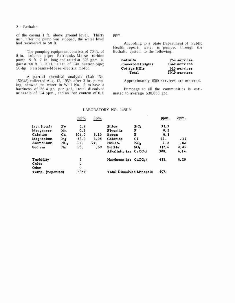
2 - Bethalto
of the casing 1 ft. above ground level. Thirty min. after the pump was stopped, the water level had recovered to 58 ft.
The pumping equipment consists of 70 ft. of 8-in. column pipe; Fairbanks-Morse turbine pump, 9 ft. 7 in. long and rated at 375 gpm. a-gainst 300 ft. T. D. H. ; 10 ft. of 5-in. suction pipe; 50-hp. Fairbanks-Morse electric motor.
A partial chemical analysis (Lab. No. 150348) collected Aug. 12, 1959, after 3 hr . pump-ing, showed the water in Well No. 5 to have a hardness of 26.4 gr. per gal . , total dissolved minerals of 524 ppm., and an iron content of 0. 6
ppm.
According to a State Department of Public Health report, water is pumped through the Bethalto system to the following:
Approximately 1500 services are metered.
Pumpage to all the communities is esti-mated to average 530,000 gpd.
LABORATORY NO. 146819

Illinois State Water Survey Bulletin 40 - Supplement II
BLACK HAWK HEIGHTS DuPage County July 7, 1958
Black Hawk Heights, a subdivision located between Clarendon Hills and Westmont, purchas-ed water from Westmont until 1953 when a well and treatment plant was constructed. The water works system was purchased in 1955 by the Illinois Municipal Water Co. and operated as the Black Hawk Heights Water Co.
WELL NO. 1 was drilled in 1953 to a depth of 295 ft. by Layne-Western Co., Aurora, and located 2573 ft. S. and 1517 ft. E. of the N. W. corner of Section 10, T38N, R11E. The ground elevation at the well is 760. The well was cased with 12-in. pipe to a depth of 140 ft., below which the hole was finished 12 in. in diameter to the bottom.
A production test was conducted on Apr. 17, 1953 by representatives of the Drilling Contractor and the State Water Survey. For test purposes the well was equipped with 130 ft. of 6-in. column pipe; 3-stage Layne and Bowler turbine pump, 4 ft. long, with a Johnston right angle gear head con-nected by a drive shaft to a gasoline engine. A plastic air line, 131 ft. long, was installed. After 8 hr. pumping at a rate of 210 gpm., the draw-down was 24 ft. below a nonpumping water level of 102 ft. below the top of the casing. Six min. after pumping was stopped, the water level had recover-ed to 102 ft.
The permanent pump assembly includes 150 ft. of 5-in. column pipe; Layne and Bowler tur-bine pump, 5 ft. 8 in. long, and rated at 2 00 gpm. against 295 ft. T.D.H.; 10 ft. of 6-in. suction pipe; 150 ft. of air line; 20-hp. U S electric motor.
Analysis of a sample (Lab. No. 147067) col-lected June 11, 1958 showed the water in Well No. 1 to have a hardness of 30 gr. per gal., total dis-solved minerals of 696 ppm., and an iron content
of 2. 7 ppm.
In 1955, when the water works system was completed there were 270 services, all metered.
Metered pumpage from May 1 to Aug. 1, 1957 averaged 49, 000 gpd., and from May 1, 1957 to Apr. 30, 1958 pumpage averaged 45, 000 gpd.
Sample study summary log of WELL NO. 1 fur-nished by the State Geological Survey
LABORATORY NO. 147067

Illinois State Water Survey Bulletin 40 - Supplement II
BLUE CREST SUBDIVISION Cook County October 6, 1958
A public water supply was installed in 1956 for the Blue Crest Subdivision (est. 220), some-times called Dowe Subdivision, located about 3/4 mile southwest of Alsip. The water system is owned and operated by the Doweville Water Co. Water is obtained from one well.
WELL NO. 1 was completed in 1956 to a depth of 349 ft. by J. P. Miller Artesian Well Co., Brookfield, and located north and east of Central Ave. at 127th St., or approximately 400 ft. N. and 300 ft. E. of the S. W. corner of Sec-tion 28, T37N, R13E. The ground surface ele-vation at the well is 598. The well was cased with 10-in. pipe, cemented in, from about 18 in. above the pump house floor to 50 ft. The hole was finished 10 in. in diameter to the bottom.
In a production test in Aug. 1956, during pumping at 250 gpm., the drawdown was 36 ft. from a nonpumping water level of 21 ft. below
the pump base. Subsequently, the permanent pumping equipment was installed to include 100 ft. of 5-in. column pipe; 8-in., 7-stage Peer-less turbine pump, No. 121040; rated at 250 gpm. at 172 ft. T.D.H.; 10 ft. of 5-in. suction pipe; 100 ft. of air line; 15-hp. U S electric motor.
In June 1958, during pumping at 250 gpm., the drawdown was 16 ft. from a nonpumping wa-ter level of 13 ft. below the pump base.
A mineral analysis of a sample (Lab. No. 147020) collected June 11, 1958 showed the water in the subdivision well to have a hardness of 27. 6 gr. per gal., total dissolved minerals of 565 ppm., and an iron content of 1. 3 ppm.
There are 55 services installed with a total of 130 expected when construction is completed. Pumpage is estimated to average 11,000 gpd.
LABORATORY NO. 147020

Illinois State Water Survey Bulletin 40 - Supplement II
BLUFFS Scott County June 29, 1960
Two wells are in service for the village of Bluffs (779).
WELL NO. 1, described in Bulletin 40, has been abandoned.
WELL NO. 2, described in Bulletin 40, is in service.
WELL NO. 3 was completed in Oct. 1958 to a depth of 59 ft. 5 in. by Layne-Western Co., St. Louis, Mo., and located about 50 ft. east of the pump station, or approximately 5 ft. S. and 755 ft. W. of the N. E. corner of Section 16, T15N, R13W. The elevation of the ground surface at the well is 460. Well No. 3 was cased with 26-in. pipe from the surface to 25 ft. and cemented in. The hole was drilled 34 in. in diameter from the surface to the bottom at 59 ft. 5 in. An inner casing, 12 in. in diameter, was set from the sur-face to 49. 5 ft. followed by a 15 ft. length of La.yne No. 5 stainless steel shutter screen, seat-ed on the bedrock. The annulus between the two casings and between the 12-in. casing and screen and the wall of the 34-in. hole, was filled with gravel,
A production test was conducted on Oct. 9, 1958 by representatives of the Driller, the State
Water Survey, and Village officials. After 8 hr. pumping at 250 gpm., the drawdown was 12.2 ft. from a nonpumping water level of 19. 4 ft. below the pump base (7 in. above ground level). Forty-five min. after the pump was stopped, the water level had recovered to 22 ft.
During the test, water levels were noted in two observation wells, No. 1 and 2, located respectively 60 and 58 ft. from the pumped well (No. 3). When the pumping was stopped, the water level in O. W. No. 1 had lowered 5.1 ft. from the static level of 24.2 ft. Thirty-four min. later the water level had raised to 26. 8 ft.
In O. W. No. 2 the water level lowered, during the test, 6. 3 ft. from a static level of 22.4 ft. Thirty-four min. later the water level in O. W. No. 2 had raised to 25 ft.
A mineral analysis of a sample (Lab. No. 152613) collected June 29, 1960 showed the water in Well No. 3 to have a hardness of 32. 2 gr. per gal., total dissolved minerals of 679 ppm., and an iron content of 2. 7 ppm.
There are 375 services. Pumpage is esti-mated to average 40,000 gpd.
LABORATORY NO. 152613

Illinois State Water Survey Bulletin 40 - Supplement II
BRICKMAN MANOR SUBDIVISION Cook County April 8, 1960
One well is in service for the Brickman Manor Subdivision (est. 500) located about 1 mile northeast of Mount Prospect and 1/4 mile south-east of Prospect Heights. The system is owned and operated by Chicago Suburban Utilities Co.
WELL NO. 1 was completed in July 1958 to a depth of 213 ft. by Hoover Water Well Service, Zion. The well was drilled reportedly for Brick-man Manor Subdivision at a location 37 ft. S. and 50 ft. W. of the N. E. corner of Section 34, T42N, R11E. The well was cased from the surface to 105 ft. (limestone) with 12-in. pipe, below which the hole was finished 12 in. in diameter to the bottom. The ground surface elevation at the well is 691. A production test July 29, 1958 was reported by the Driller. After 24 hr. pumping at a rate of 200 gpm., the drawdown was 62 ft. from a static water level of 38 ft. below the pump base (2 ft. above L. S. D. ).
The pumping equipment includes a Univer-sal submersible pump, No. UEKE2597, rated at 150 gpm., connected to a 15-hp. electric motor.
A mineral analysis of a sample (Lab. No. 152022) collected Apr. 8, 1960, after 5min. pump-ing at 150 gpm., showed the water in this well to have a hardness of 14. 2 gr. per gal., total dis-solved minerals of 458 ppm., and an iron content of 0. 3 ppm.
WELL NO. 2 was completed to a depth of 1468 ft. in Aug. 1959 by Milaeger Well and Pump Co., Inc., Milwaukee, Wis., and located on the south side of Euclid Ave. about 1/2 mile east of Elmhurst Road, or approximately 2450 ft. N. and 1400 ft. E. of the S. W. corner of Section 26, T42N, R11E. The ground surface elevation
at the well is 661. The well was cased with 20-in. pipe from the surface to 97 ft. and with 16-in. pipe from the surface to 640 ft. (cemented in). A 14-in. liner was set from 1000 to 1200 ft. depth, below which the hole was finished at 12 in. in diameter to the bottom at 1468 ft.
A production test was conducted on Aug. 24, 1959 by representatives of the Driller, the State Water Survey, and Charles W. Greengard Associates, Consulting Engineers. After 12 hr. pumping at a rate of 480 gpm., the drawdown was 68 ft. from a static water level of 360 ft. below the top of the casing (3 ft. above L. S. D. ). Considerable sand was pumped from the well and the test was stopped in order to clean out the well.
On Oct. 1-2, 1959 the Driller reported a secondproduction test. For the test the well was equipped with 480 ft. of 6-in. column pipe; 8-in., 5-stage American Well Works test turbine with 20 ft. of bowl section and suction pipe; 480 ft. of air line; 3 diesel engines. After 24 hr. pumping at a rate of 964 gpm., the drawdown was 135 ft. from a static water level of 365 ft. below the top of the casing. Ten min. after the pump was stop-ped, the water level had recovered to 404 ft.
A partial chemical analysis of a sample (Lab. No. 150735) collected Oct. 2, 1959, after 23 hr. pumping at a rate of 942 gpm., showed the water in Well No. 1 to have a hardness of 18. 9 gr. per gal., total dissolved minerals of 566 ppm., turbidity of 44 ppm., and an iron content of 2. 1 ppm.
There are 125 services. Pumpage is esti-mated to average 25, 000 gpd.
LABORATORY NO. 150735

2 - Brickman Manor Subdivision
LABORATORY NO. 152022

Illinois State Water Survey Bulletin 40 - Supplement II
BRIDGEVIEW Cook County June 4, 1959
A public water supply was installed for the village of Bridgeview (7334) about 1953 to 1955. Water is obtained from three wells which serve three separate sections of Bridgeview. Neither the wells nor the distribution systems are inter-connected.
Bridgeview WELL NO. 1 (formerly Bridge-view Manor Subdivision Well) was completed in June 1953 to adepth of 340 ft. by Beddecker Water Well Co., Oak Lawn. The well is located at the northeast corner of 78thand Beloit St. in Bridge-view, or approximately 250 ft. N. and 2000 ft. W. of the S. E. corner of Section 25, T38N, R12E. The ground surface elevation at the well is 620.
According to a State Department of Public Health report, the well is cased with 8-in. black gwi. pipe from the ground surface to 85 ft. The top of the casing was left 3 ft. above the floor of the concrete well pit, which was about 10 ft. by 8 ft. by 6 ft. deep. The well is equipped with a Deming turbine pump, No. 15994, rated at 250 gpm. and connected to a 10-hp. Deming electric motor.
Analysis of a sample (Lab, No. 147975) col-lected Oct. 16, 1958 showed the water in Well No. 1 to have a hardness of 35. 5 gr. per gal., total dissolved minerals of 879 ppm., and an iron content of 0. 9 ppm.
Bedford Park District well furnishes water to a section of Bridgeview, known as Bridgeview Gardens. The well is described in Bulletin 40 under Bedford Park District. It is located in Bedford Park at 66th Place and 78th Ave., or approximately 2550 ft. S. and 1800 ft. E. of the
N. W. corner of Section 24.
A partial chemical analysis of a sample (Lab. No. 147978) collected Oct. 16, 1958 show-ed the water in the Bedford Park well to have a hardness of 33. 3 gr. per gal., total dissolvedmin-erals of 945 ppm., and an iron content of 0. 7 ppm.
Bridgeview WELL NO. 3 was completed in Nov. 1956 to a depth of 200 ft. by Olden Pump and Supply Co., Justice, and located near Roberts Road (80th Ave. ) between 82nd Place and 82nd St., or approximately 2200 ft. S. and 200 ft. E. of the N. W. corner of Section 36. The ground surface elevation at the well is 620.
The well is cased with 6-in. gwi. pipe to 80 ft.
The pumping equipment includes 80 ft. of 3-in. column pipe; 3 5/8-in. Jacuzzi turbine pump, No. 3M4-8, rated at 75 gpm. connected to a 3-hp. Century electric motor.
A partial chemical analysis of a sample (Lab. No. 147981) collected Oct. 16, 1958 showed the water from Well No. 3 to have a hardness of 56 gr. per gal., total dissolved minerals of 1388 ppm., and an iron content of 2. 5 ppm.
The three wells previously described fur-nish all of the water for Bridgeview. Five other wells have been abandoned. Reportedly there are 390 services in the village. The supply is not metered and only about 50% of the population is served.
Pumpage is estimated to average 100, 000 gpd.
LABORATORY NO. 147975

Illinois State Water Survey Bulletin 40 - Supplement II
BROOKHAVEN MANOR DuPage County February 18, 1959
Brookhaven Manor, a subdivision located near Clarendon Hills, installed a public water supply in 1957.
WELL NO. 1 was drilled in 1957 to a depth of 310 ft. by James Bilskey, Hinsdale, and located 3100 ft. S. and 350 ft. E. of the N. W. corner of Section 27, T38N, R11E. The ground elevation at the well is 755. The well was cased with 16-in. black iron pipe from the surface to 115 ft., below which the hole was finished 15 1/2 in. in diameter to the bottom.
The pumping equipment includes a Reda submersible pump, No. 65074, rated at 276 gpm. attached to 280 ft. of 3-in. drop pipe. Power is furnished by a 20-hp. electric motor. On May 5, 1958 the nonpumping water level was 114 ft. 3 in. below the pump base and the pumping rate report-ed to be 400 gpm. The drawdown was reported to be 140 ft.
Analysis of a sample (Lab. No. 146606) col-lected May 5, 1958, after l/2 hr. pumping at a rate of 400 gpm., showed the water to have a hardness of 33. 7 gr. per gal., total dissolved
minerals of 729 ppm., and an iron content of 2. 9 ppm.
The subdivision has 40 services, all meter-ed. When completed, the system is expected to have 300 services. It is planned to drill a second well about March 1959.
Pumpage at the present is estimated to average 7000 gpd.
Correlated driller's log of WELL NO. 1 furnished by the State Geological Survey
LABORATORY NO. 146606

Illinois State Water Survey Bulletin 40 - Supplement II
BUFFALO GROVE Cook County February 9, 1960
A public water supply was installed in 1957 for Buffalo Grove (1492) recently incorporated. The water system is owned and operated by the Buffalo Grove Utility Co.
A 5-in. well was drilled in Mar. 1957 to a depth of 150 ft. by J. P. Miller Artesian Well Co., Brookfield, and located 654 ft. S. and 1226 ft. E. of the N. W. corner of Section 4, T42N, R11E. The ground elevation at the well is 680. The Driller reported a static water level of 40 ft. and water was pumped for 1 hr. at a rate of 50 gpm.
A partial analysis of a sample (Lab. No. 142848) collected Mar. 8, 1957 showed the water to have a hardness of 19. 5 gr. per gal., total dissolved minerals of 712 ppm., and an iron con-tent of 1. 8 ppm.
WELL NO. 1 has been abandoned and filled with concrete.
WELL NO. 2 was completed in Nov. 1957 to a depth of 1340 ft. by J. P. Miller Artesian Well Co. and located about 2000 ft. west of Well No. 1, or approximately 730 ft. S. and 350 ft. W. of the N. E. corner of Section 5, T42N, R11E. The ground elevation at the well is 686. The hole and casing record is shown in Table A.
The permanent pumping equipment includes 450 ft. of 6-in. column pipe; 10-in., 13-stage
Peerless turbine pump, No. 30388, rated at 400 gpm.; 450 ft. of air line (defective Nov. 25, 1958); 75-hp. U S electric motor.
TABLE A
Hole Record
18-in. from 0 to 173 ft. 12 1/2-in. from 173 to 1148 ft. 10-in. from 1148 to 1340 ft.
Casing Record
18-in. from 0 to 173 ft. 13 3/8-in. from 0 to 500 ft. (cemented)
On Nov. 24, 1958, after 18 hr. pumping at a rate of 670 gpm., the drawdown was 138 ft. from a nonpumping water level of 292 ft. below the top of the casing.
A mineral analysis of a sample (Lab. No. 148334) collected Nov. 24, 1958 showed the water in Well No. 2 to have a hardness of 17. 8 gr. per gal., total dissolved minerals of 449 ppm., and an iron content of 0. 3 ppm.
Well No. 2 furnishes the entire municipal supply.
There are now 130 services installed. Pumpage is estimated to average 35, 000 gpd.
LABORATORY NO. 148334
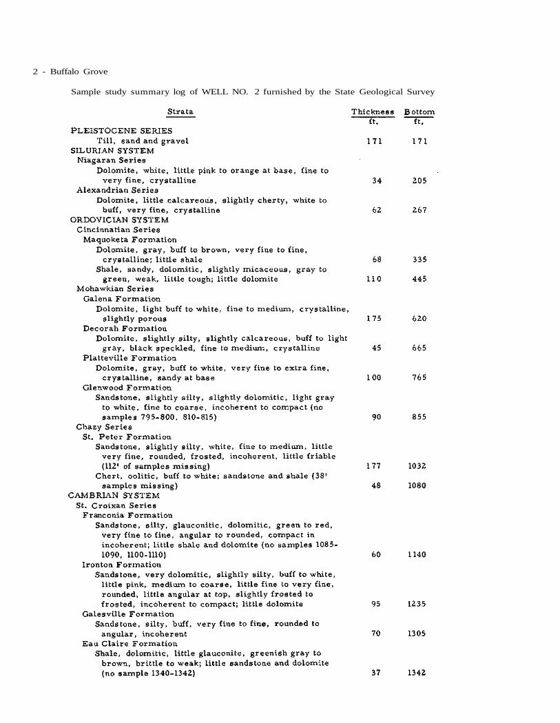
2 - Buffalo Grove
Sample study summary log of WELL NO. 2 furnished by the State Geological Survey

Illinois State Water Survey Bulletin 40 - Supplement II
BURLINGTON Kane County October 21, 1960
Two wells are in service for the public wa-ter supply of the village of Burlington (360).
WELL NO. 1, described in Bulletin 40, is in service.
WELL NO. 2 was completed in Jan. 1960 to a depth of 1105 ft. by L. Cliff Neely, Batavia, and located about 15 ft. northeast of Well No. 1, or approximately 985 ft. S. and 40 ft. W. of the N. E. corner of Section 9, T41N, R6E. The ground surface elevation at the well is 920. The well was cased with 12-in. pipe from the surface to 186 ft. and with 10-in. pipe from the surface to 343 ft. 10 in. (cemented in), below which the hole was finished 10 in. in diameter to the bottom at 1105 ft.
A production test was conducted by the Driller on Jan. 26-27, 1960. For the test a Peerless turbine pump was set at 385 ft. and directly connected to a diesel engine. After 23 hr. pumping at rates varying from 99 to 266 gpm., the drawdown was 42 ft. from a static water level of 275 ft. below the pump base, 2 ft. above ground level. Twenty min, after the pump
was stopped, the water level had recovered to 280 ft.
A partial chemical analysis of a sample (Lab. No. 151555) collected Jan. 27, 1960, after 23 hr. pumping, showed the water in Well No. 2 to have a hardness of 14.9 gr. per gal., total dissolved minerals of 321 ppm., and an iron content of 3.1 ppm.
The permanent pumping equipment, in-stalled in Oct. 1960, consists of 405 ft. of 4-in. column pipe; 8-in., 12-stage Layne submersible pump, rated at 230 gpm. against 348 ft. T.D.H.; 405 ft, of air line; 30-hp. U S electric motor.
On Oct. 21, 1960, while pumping at 230 gpm. for 2 hr., the drawdown was 36 ft. from a nonpumping water level of 269 ft. below the pump base.
There are 210 services installed, all of which are metered, and about 95% of the popu-lation is served. Pumpage for 1959 was esti-mated to average 10, 000 gpd.
LABORATORY NO. 151555

2 - Burlington
Summary sample study log of WELL NO. 2 furnished by the State Geological Survey

Illinois State Water Survey Bulletin 40 - Supplement II
CABERY Ford County June 24, 1960
Two wells are in service for the village of Cabery (293).
WELL NO. 1, described in Bulletin 40 as the Park Well, was abandoned years ago.
WELL NO. 2, described in Bulletin 40 as the well drilled by Lars Jensen, Clifton, to a depth of 233 ft. in 1920, is maintained for stand-by use.
WELL NO. 3 was completed in Nov. 1956 to a depth of 357 ft. by J. Bolliger and Sons, Fairbury, and located at the south edge of town, about 650 ft. southeast of Well No. 2, or approx-imately 800 ft. S. and 600 ft. E. of the N. W. corner of Section 16, T29N, R9E. The ground surface elevation at the well is 700. The well was cased with 8-in. pipe from 3 ft. above the surface to 214 ft. 10 in., below which the hole was finished 8 in. in diameter.
When the well was completed, the Driller reported pumping 4 hr. at a rate of 125 gpm. with a drawdown of 34 ft. from a nonpumping water level of 48 ft. below the surface.
The permanent pump installation is a Dem-ing turbine attached to 100 ft. of column pipe and connected to a 7 l/2-hp. U S electric motor.
A mineral analysis of a sample (Lab. No.
152585) collected June 24, 1960 showed the water to have a hardness of 37.2 gr. per gal., total dissolved minerals of 1619 ppm., and an iron con-tent of 0. 2 ppm.
There are 105 services, none metered, and 100% of the population is served. Pumpage in July 1958 was reported to average 22,000 gpd.
Correlated driller's log of WELL NO. 3 furnish-ed by the State Geological Survey
LABORATORY NO. 152585

Illinois State Water Survey Bulletin 40 - Supplement II
CAMP POINT Adams County June 29, 1960
Three wells are in service for the public water supply of the village of Camp Point (1092).
WELL NO. 1, the dug well described in Bulletin 40, is not in service.
WELL NO. 2, described in Bulletin 40 as the well drilled by Henry Schuster in 1947, was abandoned and disconnected from the system about 1953 and later was filled.
WELL NO. 3, described in Bulletin 40, was equipped in 1955 with a new Burks centrifu-gal pump, rated at 1000 gal. per hr.
In Mar. 1959 this well was being used 24 hr. daily.
WELL NO. 4 was completed in July 1955 to a depth of 40 ft. by Elmer Franke, Calhoun Drilling Co., Batchtown, and located about 200 ft. northeast of the railroad reservoir, or ap-proximately 400 ft. S. and 75 ft. E. of the N. W. corner of Section 35, T1N, R6W. The ground surface elevation at the well is 680.
The well was cased with 8-in. standard pipe from 2 ft. above to 34 ft. below the ground level, followed by a 6 ft. length of 6-in. Cook well screen, Everdur metal.
After the well was completed, water was pumped for 4 hr. at a rate of 38 gpm. The draw-down was 28 ft. 9 3/4 in. from a static level of 20 ft. below the surface.
The pumping equipment includes a Myers Ejecto pump connected to a 1-hp. General Elec-
tric motor. The estimated capacity of the well is 8-10 gpm.
Correlated driller's log of WELL NO. 4 furnish-ed by the State Geological Survey
Strata Thickness Bottom ft. ft.
PLEISTOCENE SERIES Till, sand dirty; clay 34 34 Sand, coarse; gravel
fine 6 40
A mineral analysis of a sample (Lab. No. 152607) collected June 29, 1960 showed the wa-ter to have a hardness of 34. 6 gr. per gal., total dissolved minerals of 708 ppm., and an iron content of 0.1 ppm.
Well No. 4 is in service.
WELL NO. 5 was constructed in 1955 to a depth of 36 ft. and reportedly deepened in Sept. 1959 to 56 ft. It is located about 60 ft. east of Well No. 4.
The hole was drilled 10 in. in diameter and a 6-in. casing and screen were set with the bot-tom of the screen at 44 ft. The annulus between the casing and screen and the wall of the hole was gravel packed.
Pumping equipment is identical with that in Well No. 4 and the well capacity is estimated at 8-10 gpm. Well No. 5 is in service.
There are 400 services, all metered. Pumpage is estimated to average 43, 000 gpd.
LABORATORY NO. 152607

Illinois State Water Survey Bulletin 40 - Supplement II
CAMPUS Livingston County October 20, 1958
Two wells are in service for the public water supply of the village of Campus (165).
WELL NO. 1 was described in Bulletin 40 as a 2-in. well which was abandoned when Well No. 2 was drilled.
WELL NO. 2, described in Bulletin 40, is now equipped with 80 ft. of 4-in. column pipe; 6-in., 13-stage Pomona turbine pump, No. AK6175, rated at 100 gpm. against 165 ft. T.D.H.; 80 ft. of air line; 7 l/2-hp. Fairbanks-Morse electric motor.
On Oct. 20, 1958 the nonpumping water level was 39 ft.
WELL NO. 3 (formerly Wabash Railroad Well) was purchased from the railroad in 1954 and connected to the village system sometime in 1955. The well had been drilled for the railroad
in 1925 to a depth of 174 ft. by R. R. Hopper, Wellington, and located about 900 ft. west of village Well No. 2, or approximately 725 ft. N. and 1200 ft. W. of the S. E. corner of Section 33, T29N, R8E. The ground surface elevation at the well is 650. The well was reportedly cased with 24-in. pipe from the surface to 125 ft. and with 18-in. pipe from the surface to 133 ft. followed by 30 ft. of 18-in. screen.
The pumping equipment consists of 120 ft. of 7-in. column pipe; 10-in., 6-stage Layne tur-bine pump, No. 3718, rated at 350 gpm.; 20-hp. General Electric motor.
There are two storage tanks, one of 100, 000 gal. capacity formerly owned by the Wabash Railroad and purchased by the village with the well, and the village tank of 25,000 gal. capacity.
Pumpage is estimated to average 13,000 gpd.

Illinois State Water Survey Bulletin 40 - Supplement II
CAROL STREAM DuPage County September 9, 1960
A public water supply was installed in 1958 for Carol Stream Subdivision incorporated in 1959 as village of Carol Stream (836) located about 2 miles northwest of Wheaton. The subdivision is being laid out by the Durable Construction Co.
WELL NO. 1 was completed in Aug. 1958 to a depth of 335 ft. by Layne-Western Co., Aurora, and located 1033 ft. S. and 925 ft. W. of the N. E. corner of Section 31, T40N, R10E. The ground surface elevation at the well is 764. The well is cased with 10-in. steel pipe to 118 ft., below which the hole is 10 in. in diameter to the bottom at 335 ft.
A production test was conducted by the Driller on Aug. 15, 1958 using a 10-in., 6-stage test turbine pump attached to 145 ft. of 6-in. column pipe. After 3 hr. pumping at a rate of 509 gpm., the drawdown was 13 ft. from a non-pumping water level of 40 ft. below the top of the casing (air line readings).
A partial chemical analysis of a sample (Lab. No. 147510) collected Aug. 15, 1958, after 1 l/2 hr. pumping at a rate of 408 gpm., show-ed the water in Well No. 1 to have a hardness of 17.8 gr. per gal., total dissolved minerals of 366 ppm., and an iron content of 0. 9 ppm. The water was turbid at first but cleared after 3 1/2 hr.
The permanent pumping equipment consists of 70 ft. of 6-in. column pipe; 10-in., 4-stage Layne turbine pump, No. 39508, rated at 500 gpm. at 175 ft. T.D.H.; 10 ft. of 6-in. suction pipe; 70 ft. of air line; 30-hp. Westinghouse electric motor. Auxiliary power is available
from a Johnston right angle gear drive and a 4-cylinder Continental Red Seal gasoline engine.
Pumpage for the subdivision is estimated to average 20,000 gpd.
Summary sample study log of WELL NO. 1 fur-nished by the State Geological Survey
LABORATORY NO. 147510

Illinois State Water Survey Bulletin 40 - Supplement II
CASEY Clark County May 6, 1959
Seven wells are in service for the public water supply of the city of Casey (2890).
Two wells have been abandoned and three wells, No. 7, 8 and 9. have beenadded to the pub-lic water supply since Bulletin 40 was published.
WELLS NO. 1 and 4 have been abandoned and the suction lines disconnected.
WELLS NO. 2, 3, 5 and 6, described in Bulletin 40, are in service.
WELL NO. 7 was completed early in 1952 to a depth of 65 ft. by Gordon Green, Casey, and located 15 ft. south of Well No. 1, or approxi-mately 2515 ft. S. and 10 ft. E. of the N. W. cor-ner of Section 19, T10N, R13W. The elevation of the ground surface at the well is 580. The well is reportedly cased with 12 1/2-in. id. pipe from approximately 8 ft. below to 65 ft. below the ground surface.' The lower 17 ft. of the casing is perforated with 3/l6-in. slots. The casing top is sealed with a belted flange. The well is connected to the main suction line common to all the other wells in service.
WELL NO. 8 was completed in 1952 to a depth of 131 ft. by Gordon Green and located 15 1/2 ft. east and 95 ft. south of Well No. 7, or approximately 2610 ft. S. and 25 ft. E. of the N. W. corner of Section 19. The well is report-edly cased with 12 l/2-in. id. pipe from approxi-mately 8 ft. below to 131 ft. below the ground surface. The lower 17 ft. of the casing is per-forated. The casing top is sealed with a belted flange and the well is connected to the main suc-tion line common to all the other wells in service.
Water is pumped from the suction line con-necting Wells 2, 3, 5, 6, 7 and 8 by a Fairbanks-Morse centrifugal pump rated at 300 gpm. against 43 ft. T.D.H. Power is furnished by a 3-hp. Fairbanks-Morse electric motor. The water from these wells is treated prior to discharge to the distribution system.
WELL NO. 9 was completed in Aug. 1954 to a depth of 132 ft. by Gordon Green and located about 100 ft. northwest of Well No. 8. The well is cased with a 20-in. outer pipe from about 4 ft. above to 132 ft. below the ground surface and with a 10-in. inner pipe from 4 ft. above to 132 ft. below ground level. The annulus between the casings is filled with gravel.
The water from Well No. 9 is pumped by a Worthington turbine pump rated at 300 gpm. This well is maintained as a stand-by or emergency unit.
A mineral analysis of a sample (Lab. No. 149501) collected Apr. 30, 1959, after 10 min. pumping at 300 gpm., showed the water in Well No. 9 to have a hardness of 10.1 gr. per gal., total dissolved minerals of 865 ppm., and an iron content of 5.1 ppm.
A mineral analysis of a composite sample (Lab. No. 149499) collected Apr. 30, 1959, after 8 hr. pumping from Wells 2, 3, 5, 6, 7 and 8, showed this water to have a hardness of 16. 6 gr. per gal., total dissolved minerals of 498 ppm., and an iron content of 2. 3 ppm.
Pumpage in May 1959 was reported to aver-age 200, 000 gpd.
LABORATORY NO. 149501

2 - Casey
LABORATORY NO. 149499

I l l inois State Water Survey Bul le t in 40 - Supplement II
A wate r supply was ins ta l led in 1956 for the C a t e r p i l l a r T r a i l s Publ ic Water D i s t r i c t .
W E L L NO. 1 was comple ted to a depth of 358 ft. in 1956 by L a y n e - W e s t e r n C o . , A u r o r a , and loca ted n e a r Germantown, app rox ima te ly 50 ft. N. and 1700 ft. W. of the S. E. c o r n e r of Sect ion 29, T27N, R3W. The ground sur face e levat ion at the well is 746.
The well was cased with 10- in . p ipe , se t in a 15- in . hole , f rom the su r face to 338 ft. fol-lowed by 20 ft. of 10-in. b ronze s c r e e n . F ive cu. yd. of g rave l were packed in the annulus be-tween the s c r e e n and the wall of the 15-in. ho le .
A product ion tes t was conducted on Nov. 30-Dec . 1, 1956 by r e p r e s e n t a t i v e s of the D r i l l e r , the State Water Survey, and Caldwel l -Rhoads C o . , Consult ing E n g i n e e r s . F o r t es t p u r p o s e s
C A T E R P I L L A R TRAILS PUBLIC WATER DISTRICT Woodford County June 10, 1960
the well was equipped with an 8 - i n . , 9 - s t age Layne and Bowler tes t turbine pump; 297 ft. of a i r l ine ; C h r y s l e r engine. After 24 h r . pumping at a r a t e of 108 g p m . , the drawdown was 4 ft. below a s ta t ic wa te r level of 297 ft. Within 1 m i n . af ter the pump was s topped, the wa te r level had r e c o v e r e d to 297 ft.
A p a r t i a l chemica l ana lys i s of a s amp le (Lab . No. 142070) co l lec ted D e c . 12, 1956 show-ed the wate r in Well No. 1 to have a h a r d n e s s of 17. 5 g r . pe r g a l . , total d i s so lved m i n e r a l s of 336 p p m . , and an i ron content of 0 .9 ppm.
The p e r m a n e n t pumping equipment c o n s i s t s of 339 ft. of 4 - in . column pipe; 1 6 - s t a g e Layne turbine pump, r a t e d at 120 g p m . , aga ins t 400 ft. T . D . H. ; 20-hp . West inghouse e l e c t r i c m o t o r .
The number of s e r v i c e s and the pumpage have not been r e p o r t e d .
C o r r e l a t e d d r i l l e r ' s log of W E L L NO. 1 furn ished by the State Geological Survey

2 - Caterpillar Trails Public Water District
LABORATORY NO. 142070

Illinois State Water Survey Bulletin 40 - Supplement II
CHAIN-O'-LAKES STATE PARK Lake County May 29, 1958
A public water supply was installed at Chain-O'-Lakes State Park in Oct. 1940. The Park is located northwest of Fox Lake village.
WELL NO. 1 was drilled in Oct. 1940 to a depth of 234 ft. by Henry Boysen, Libertyville, and deepened in Dec. 1940 to 270 ft. The well is located approximately 525 ft. S. and 1250 ft. W. of the N. E. corner of Section 28, T46N, R9E. The ground surface elevation at the well is 775. The well was cased with 8-in. pipe from the surface to 218 ft., below which the hole was finished at 8 in. in diameter. Limestone was encountered at 212 ft.
A production test was conducted by repre-sentatives of the Driller and the State Water Sur-vey on Oct. 29-30, 1940. After 12 hr. pumping at a rate of 52 gpm., the drawdown was 90 ft. from a static water level of 44 ft. below the top of the casing. Thirty min. after the test was stopped, the water level had recovered to 48 ft.
After the well was deepened to 270 tt., a second production test was conducted. The cas-ing had been driven from 212 to 218 ft. After 9 hr. pumping at a rate of 40 gpm., the drawdown was 47 ft. The yield in the second test was less than in the first test. This reduction was attrib-uted to extending the casing an additional 6 ft.
and probably casing out some of the upper lime-stone water. The well was pumped for several hours after the first test and before the second test but the turbidity increased, contrary to what was expected.
A mineral analysis of a sample (Lab. No. 89174) collected Oct. 30, 1940 (well depth 234 ft. ) showed the water to have a hardness of 14. 5 gr. per gal., total dissolved minerals of 316 ppm., turbidity of 105 ppm., and an iron content of 2. 6 ppm.
A partial mineral analysis of a sample (Lab. No. 89492) collected Dec. 5, 1940 (well depth 270 ft. ) showed the water to have a hard-ness of 14. 5 gr. per gal., total dissolved min-erals of 305 ppm., turbidity of 200 ppm., and an iron content of 2. 2 ppm.
The pumping equipment includes a 3-in. column pipe (length not reported); Fairbanks-Morse turbine pump (No. 18827); 7 1/2-hp. Westinghouse electric motor.
A mineral analysis of a sample (Lab. No. 146793) collected May 29, 1958, after 10 min. pumping, showed the water in the well to have a hardness of 14. 3 gr. per gal., total dissolved minerals of 320 ppm., turbidity of 9 ppm., and an iron content of 1. 6 ppm.
LABORATORY NO. 146793

Illinois State Water Survey Bulletin 40 - Supplement II
CHAMPAIGN AND URBANA Champaign County January 10, 1961
Twenty-three wells are in service for Champaign (49,583) and Urbana (27,294). The plant and distribution system are owned and operated by the Northern Illinois Water Corpo-ration.
Champaign-Urbana wells in service:
Wells No. 2, 3, 10, 26, 29, 30, 32, 33, 35, 36, 40, 41, 42, 43, 45, 46, 47, 48, 50, 52, 53, 54, 55. No. 56 is drilled and will be put in service in 1961.
Champaign-Urbana wells abandoned:
Wells No. 7, 8, 9, 11, 12, 13, 14, 15, 16, 18, 31, 44, 49.
WELL NO. 49 caved in and was abandoned in 1957. It was replaced by Well No. 55 in 1958.
WELL NO. 50 and all wells constructed prior thereto are described in Bulletin 40.
WELL NO. 51 was constructed in Aug. 1950 to a depth of 296 ft. by Kelly Well Co., Inc., Grand Island, Neb., and located about 1/4 mile west of Well No. 50, or approximately 40 ft. N. and 955 ft. W. of the S. E. corner of Section 32, T20N, R8E. The ground surface elevation at the well is 735. A 38-in. diameter hole was drilled from the surface to 296 ft. and a concrete base plug was set in the bottom on. top of which were placed 76 lineal ft. of concrete screen blocks 22-in. od. by 17-in. id. and each block. 4 ft. in length and having 184 openings of 4 3/4 by 3/16 in. From 192 ft. to the surface, solid concrete blocks (22-in. od. by 17-in. id.) were placed.
From the bottom of the well up to 192 ft. the annulus between the concrete screen and casing and the wall of the 38-in. hole was filled with selected silica sand and gravel, spouted in through a 2-in. pipe. From 192 ft. up to 20 ft. the annulus was filled with material from the mud pit, and from 20 ft. to the surface the an-nulus was to be filled with concrete.
A production test was conducted on Aug. 14, 1950 by representatives of the Driller, the State Water Survey, and the Owner. After 24 hr. pumping at 965 gpm., the drawdown was 11 ft. from a nonpumping water level of 76.5 ft. below the top of the casing (2 ft. above ground level). One-half hour after the pump was stop-
ped, the water level had recovered to 78.9 ft. and at 24 hr. the water level had recovered to 76.5 ft. The specific capacity of Well No. 51 was 88 gpm. per ft. of drawdown. By 1954 the specific capacity declined to 50, and after a number of treatments, each of which improved the well only temporarily, the well was aban-doned.
In Nov. 1956 Well No. 54 replaced Well No. 51.
A mineral analysis of a sample (Lab. No. 130755) collected Dec. 18, 1952 showed the water in Well No. 51 to have a hardness of 14. 3 gr. per gal., total dissolved minerals of 315 ppm., and an iron content of 0. 84 ppm.
WELL NO. 52 was completed in Sept. 1956 to a depth of 313 ft. 2 in. by Thorpe Well Co., DesMoines, Iowa, and located about 3 l/2 miles east of Well No. 50, or approximately 30 ft. N. and 2628 ft. E. of the S. W. corner of Section 36, T20N, R8E. The elevation of the top of the 24-in. casing is 719. 66. A 42-in. hole was drilled from the surface to the bottom. A 36-in. casing was installed from the surface to 220 ft. and a 24-in. casing was set to 238 ft. followed by a 24-in. screen, 75 ft. in length to the bottom of the well. Between the screen and 24-in. casing and the 36-in. casing the annulus was packed with Muscatine gravel up to 10 ft. above the static level of Sept. 9, 1956. Above this point the an-nulus was filled with cement grout to the sur-face. The annulus between the 36-in. casing and the wall of the hole was filled with gravel up to 10 ft. above the bottom of the 36-in. cas-ing and above this point the annulus was filled with cement grout.
A production test was conducted on Sept. 20-21, 1956 by representatives of the Driller, the State Water Survey, and the Owner. After 48 hr. pumping at 1092 gpm., the drawdown was 2.7 ft.
A mineral analysis of a sample (Lab. No. 141514) collected Sept. 21, 1956 showed the water in Well No. 52 to have a hardness of 15. 9 gr. per gal., total dissolved minerals of 492 ppm., and an iron content of 0.2 ppm.
Well No. 52 is not equipped for pumping.
WELL NO. 53 was completed in Dec. 1956 to a depth of 289 ft. by Layne-Western Co.,

2 - Champaign and Urbana
Aurora, and located about 2 1/2 miles southeast of Well No. 50, or approximately 2690 ft. N. and 57 ft. E. of the S. W. corner of Section 2, T19N, R8E. The elevation of the top of the pump foundation is 758.05. A 42-in. hole was drilled from the surface to the bottom at 289 ft. A 26-in. outer casing and a 16-in. inner casing, fol-lowed by a 75 ft. length of stainless steel 16-in. screen, were set and gravel packed as in Well No. 52.
A production test was conducted on Dec. 26-29, 1956 by representatives of the Driller, the State Water Survey, and the Owner. Before the test was started, the well had been devel-oped over a period of several days by alter-nating the agitation and pumping of the well. Pumping was started on Dec. 26 and after 48 hr. pumping at 1500 gpm., the drawdown was 14. 2 ft. from a nonpumping water level of 117. 8 ft. below the pump base.
A mineral analysis of a sample (Lab. No. 142209) collected Dec. 29, after 48 hr. pump-ing at 1500 gpm., showed the water in Well No. 53 to have a hardness of 15. 8 gr. per gal., total dissolved minerals of 308 ppm., and an iron content of 0. 6 ppm.
The pumping equipment includes 180 ft. of 10-in. steel column pipe; 13 3/8-in. od., 4-stage water lubricated Peerless turbine pump, all bronze bowls, and connected to a 200-hp. General Electric motor.
Well No. 53 is in regular service.
WELL NO. 54 was completed in 1957 to a depth of 330 ft. by Layne-Western Co. and lo-cated at the site of Well No. 51 (abandoned), or approximately 40 ft. N. and 1016 ft. W. of the S. E. corner of Section 32. The elevation of the top of the pump foundation is 727.65. A 48-in. hole was drilled from the surface to 330 ft. The hole was double cased with a 36-in. outer casing from the surface to the top of the screen, and a 24-in. inner casing set from the surface to 255 ft. followed by a 24-in. screen, 75 ft. in length to the bottom of the hole. The annulus between the 24-in. screen and the wall of the 48-in. hole and between the 24-in. and 36-in. casings was packed with gravel up to 10 ft. above the static water level, which was 87.8 ft. below the top of the pump foundation. The annulus between the 36-in. casing and the wall of the hole was packed with gravel up to 10 ft. above the static water level. The hole between the casings and outside the 36-in. casing was filled with material from
the mud pit. The remainder of the hole was ce-ment grouted up to the surface.
A production test was conducted on Nov. 26-29, 1956 by representatives of the Driller, the State Water Survey, and the Owner. After 48 hr. pumping at 3000 gpm., the drawdown was 28.3 ft. from a nonpumping water level of 87.8 ft. below the pump foundation. The specific ca-pacity was 118.
A mineral analysis of a sample (Lab, No. 142030) collected in Dec. 1956 showed the water in Well No. 54 to have a hardness of 14.7 gr. per gal., total dissolved minerals of 312 ppm., and an iron content of 0.2 ppm.
In Aug. 1957 the new pumping installation consisted of 160 ft. of 14-in. column pipe; 15-in., 4-stage water lubricated Peerless turbine pump, all bronze bowls, and rated at 3000 gpm. against 250 ft. T.D.H.; 250-hp. General Electric motor.
Well No. 54 is in service.
WELL NO. 55 was completed in 1958 to a depth of 300 ft. by Layne-Western Co. and lo-cated about 70 ft. north of Well No. 49 (previ-ously abandoned), or approximately 865 ft. S. and 40 ft. W. of the N. E. corner of Section 5, T19N, R8E. The elevation of the top of the pump foundation is 735.20. A 42-in. hole was drilled from the surface to 300 ft. A 24-in. casing was set from the surface to 250 ft. and a 14-in. cas-ing was set to 250 ft. followed by a 14-in. stain-less steel screen, 50 ft. long to the bottom of the hole. The well was gravel packed similar to Well No. 54, the gravel pack extending from the bottom up to 10 ft. above the static water level. Above the gravel pack, the space between the casings and outside the 24-in. casing was ce-ment grouted.
A production test was conducted on May 2, 1958 by representatives of the Driller, the State Water Survey, and the Owner. After 48 hr. pumping at 900 gpm., the drawdown was 9. 24 ft., a specific capacity of 97.25.
The pumping equipment consists of 150 ft. of 8-in. column pipe; 12-in., 5-stage Peerless turbine, oil lubricated, rated at 1000 gpm. a-gainst 225 ft. T.D.H.; 75-hp. U S electricmotor.
Well No. 55 is in regular service.
A mineral analysis of a composite sample (Lab. No. 150853) collected Oct. 21, 1959, be-

Champaign and Urbana - 3
fore aeration, from Wells No. 35, 41, 42, 54 and 55, showed the water to have a hardness of 15.7 gr. per gal., total dissolved minerals of 347 ppm., and an iron content of 1. 2 ppm.
The potential production of the two well fields (West and Plant) is presently estimated by the Owner to be 18 mgd. and this should be
increased in a year or so to 23 mgd.
For the year 1960, pumpage from the West well field averaged 6. 4 mgd. (includes 1. 75 mgd. to the University of Illinois). Pumpage from the Plant well fieldaveraged 1.47 mgd. Totalpump-age for Champaign-Urbana for the year 1960 av-eraged 7.87 mgd.
LABORATORY NO. 142030
LABORATORY NO. 150853

4 - Champaign and Urbana
Correlated sample study log of WELL NO. 53 furnished by the State Geological Survey

Illinois State Water Survey Bulletin 40 - Supplement II
CHATSWORTH Livingston County September 19, 1960
Three wells are in service for the town of Chatsworth (1330). Two more wells have been constructed and will be available for service as soon as pumps are installed.
WELL NO. 1, described in Bulletin 40, is in service.
WELL NO. 2 was completed in May 1949 to a depth of 67 ft. by Hayes and Sims, Cham-paign, and located about 1100 ft. due west of Well No. 1, or approximately 2500 ft. S. and 170 ft. E. of the N. W. corner of Section 3, T26N, R8E. The land surface elevation at the well is 734.
The well was cased with 12-in. pipe from 1. 5 ft. above to 57. 3 ft. below ground level fol-lowed by 10 ft. of 12-in. Johnson Everdur screen, having No. 40 slot openings.
The pumping equipment consists of 50 ft. of 4-in. column pipe; 5 5/8-in., 7-stage Aurora turbine pump rated at 120 gpm.; 3-hp. U S elec-tric motor.
A production test was conducted on May 17, 1949 by representatives of the Driller. After 6 hr. pumping at a rate of 200 gpm., the draw-down was 11 ft.
A mineral analysis of a sample (Lab. No. 119574) collected Oct. 7, 1949, after 1 hr. pump-ing at 125 gpm,, showed the water to have a hard-ness of 24 gr. per gal., total dissolved minerals of 531 ppm., and an iron content of 1. 9 ppm.
WELL NO. 3 was completed in May 1958 to a depth of 99 ft. by Sims Drilling Co., Cham-paign, and located about 1/4 mile northeast of Well No. 2, or approximately 750 ft. S. and 650 ft. E. of the N. W. corner of Section 3. The land surface elevation at the well is 720. The well was cased with 12-in, pipe from 3 ft. above to 91 ft. 8 in. below land surface followed by 12-in. Johnson Everdur screen to 99 ft. 6 in. The screen had No. 35 slot openings.
A production test was conducted on June 6, 1958 by representatives of the Driller, the State Water Survey, and Tracy Pitzen, Consulting Engineer. For test purposes the well was e-quipped with a Fairbanks-Morse turbine test pump connected to a 110-hp. Ford industrial gas
engine. A 90-ft. air line was installed for meas-uring water levels. After 9 hr. pumping at a rate of 160 gpm., the drawdown was 41. 5 ft. from a static water level of 45 ft. Thirty min. after pumping was stopped, the water level had re-covered to 61. 5 ft.
A partial chemical analysis of a sample (Lab. No. 146814) collected June 6, 1958, after 7 hr. pumping at 165 gpm., showed the water in Well No. 3 to have a hardness of 29. 7 gr. per gal., total dissolved minerals of 639 ppm., and an iron content of 1. 5 ppm.
WELL NO. 4 was completed in June 1960 to a depth of 232 ft. by Sims Drilling Co. and located about 3/4 mile northeast of Well No. 3, or approximately 1200 ft. N. and 1400 ft. E. of the S. W. corner of Section 34, T27N, R8E. The well was cased with 206 ft. of 12-in. pipe.
A production test was conducted by the Driller on June 7, 1960. After 6 hr. pumping at a rate of 207 gpm., the drawdown was 73. 6 ft. from a nonpumping water level of 50 ft. below a measuring point 2. 5 ft. above the ground sur-face.
A partial chemical analysis of a sample (Lab. No. 152594) collected June 21, 1960, after 6 hr. pumping at a rate of 207 gpm., showed the water in Well No. 4 to have a hardness of 29. 3 gr. per gal., total dissolved minerals of 699 ppm., and an iron content of 2. 8 ppm.
The permanent pump has not been in-stalled.
WELL NO. 5 was completed in Sept. 1960 to a depth of 223 ft. by Sims Drilling Co. and lo-cated about l/4 mile north of Well No. 4, or approximately 2700 ft. S. and 1600 ft. E. of the N. W. corner of Section 34. The well was cas-ed with 12-in. pipe from 3 ft. above to 203 ft. below the land surface followed by 21 ft. of screen with slot section as follows: 5 ft. of No. 12; 4 ft. of No. 20; 5 ft. of No. 30; 4 ft. of No. 20; 3 ft. of No. 15 at the bottom.
A production test was conducted on Sept. 19, 1960 by representatives of the Driller, the State Water Survey, and Farnsworth and Wylie, Consulting Engineers. For test purposes the

2 - Chatsworth
well was equipped with a 6-in., 6-stage Pomona turbine test pump set at 140 ft. and operated from a gas engine. After 4 hr. pumping at 200 gpm., the drawdown was 16. 5 ft. from a non-pumping water level of 39. 5 ft. One hr. after the test was stopped, the water level had re-covered to 41. 1 ft.
A partial analysis of a sample (Lab. No. 153257) collected Sept. 19, 1960, after 4 hr.
pumping at 200 gpm., showed the water in Well No. 5 to have a hardness of 25. 6 gr. per gal., total dissolved minerals of 636 ppm., and an iron content of 2. 2 ppm.
The permanent pump has not beeninstalled.
There are 445 services, 95% of which are metered, and 100% of the population is served. Pumpage in 1958 average 120,000 gpd.
LABORATORY NO. 153257

Illinois State Water Survey Bulletin 40 - Supplement II
CHEBANSE Iroquois County June 24, 1960
Two wells are in service for the village of Chebanse (995).
WELL NO. 1, described in Bulletin 40, is equipped with a Peerless turbine pump, rated at 100 gpm., connected to a 7 l/2-hp. U S electric motor.
WELL NO. 2 was completed in Apr. 1957 to a depth of 150 ft. by Layne-Western Co., Aurora, and located 15 ft. east of Well No. 1, or approx-imately 400 ft. S. and 2000 ft. W. of the N. E. corner of Section 14, T29N, R14W. The elevation of the ground surface at the well is 660. The well was cased with 10-in. steel pipe to 85 ft. below which the hole was finished 10 in. in diam-eter.
A production test was conducted by the Driller on Apr. 9, 1957. After 2 1/2 hr. pump-ing at 323 gpm., the drawdown was 20 ft. from a nonpumping water level of 45 ft. below the sur-face. In Well No. 1, 15 ft. to the west of No. 2, the drawdown was 14 ft.
The pump in No. 1 was then started and with both pumps operating, the drawdown in Well No. 2, after 1 1/2 hr. pumping at 214 gpm., was 19 ft. During the same period Well No. 1 was pumped at 859 gpm. with a drawdown of 16 ft.
The permanent pump in Well No. 2 is a Westinghouse turbine, rated at 200 gpm. and set
at 78 ft., connected to a 15-hp. Westinghouse electric motor.
A mineral analysis of a sample (Lab. No. 152589) collected June 24, 1960 showed the water in Well No. 2 to have a hardness of 17. 6 gr. per gal., total dissolved minerals of 501 ppm., and an iron content of 0.1 ppm.
There are approximately 216 services, 6 of which are metered, and 100% of the population is served. Pumpage is estimated to average 35,000 gpd.
Sample study log of WELL NO. 2 furnished by the State Geological Survey
LABORATORY NO. 152589

Illinois State Water Survey Bulletin 40 - Supplement II
CHICAGO HEIGHTS Cook County April 12, 1960
Since Bulletin 40 was published, four old wells of the city of Chicago Heights (34, 331) have been rehabilitated and restored to service, and two additional wells have been constructed. Cur-rently there are nine wells in service as follows: Wells No. 12, 14, 15, 16, 17, 18, 21, 22 and 23. Wells No. 24 and 25 were constructed in 1958 but have not been equipped with pumps.
WELL NO. 12, described in Bulletin 40, was rehabilitated in Apr. 1955 by Wehling Well Works, Beecher. The well was redrilled and cleaned out from 157 ft. to its original depth of 201 ft. The redrilling was started with an 11 1/2-in. bit reduced to 10 in. at 172 ft. Due to ob-struction of a line shaft, previously dropped in the well, an 8-in. bit was used to the bottom. Reportedly, a suggestion was made by the Con-tractor to "fish out the obstruction" but, since the bowls could be set at 160 ft., the suggestion was officially rejected.
The pumping equipment installed after the rehabilitation work included 140 ft. of 8-in. col-umn pipe; 10-in., 6-stage Byron Jackson pump, all bronze bowl assembly; 20 ft. of 8-in. suction pipe (reinstalled); 40-hp. nonreversible ratchet electric motor. The Contractor reported that after 1 hr. pumping at a rate of 620 gpm. against a main pressure of 45 lb. the drawdown was 3 ft. In Jan. 1957 the Contractor reported the well was producing at the same rate.
There has been no change in WELL NO. 14 since Bulletin 40. The pumping rate is approx-imately 800 gpm.
WELL NO. 15, described in Bulletin 40, was reconditioned by Wehling Well Works in Nov. 1956. The pump had reportedly broken suction at 195 ft. during pumping at a rate of 900 gpm. The well was cleaned out to its original depth of 200 ft. and then deepened to a total depth of 428 ft. where a shale formation was encountered. Because the 24-in. casing was in poor condition, a 20-in. casing was set from the surface to 104 ft. and the annular space between the casings was cemented in. The Contractor reported that "the American Well Works pump was reinstalled and a pumping test with same showed 1500 gpm. with open discharge from 134 ft. to 140 ft. and only 6 ft. drawdown. "
WELL NO. 16, which had not been in oper-ation for some time, was cleaned out in Dec. 1956
to its original depth of 235 ft. by Wehling Well Works. The well was then deepened to a total depth of 428 ft. "where soft formation was en-countered and the drilling terminated. " The Con-tractor reported that a pumping test was not made at the time and that the plans were "to in-stall the old pump and replace all column pipe in the spring of 1957. " This well is now in use.
WELL NO. 17 was reportedly returned to service Feb. 11, 1956 on the basis of about 10 hr. daily. In 1956, during pumping at a rate of 950 gpm., the drawdown was 92 ft. from a nonpump-ing water level of 132 ft. below the pump base.
There has been no change in WELL NO. 18 since Bulletin 40.
WELL NO. 19 has been abandoned since about 1950.
WELL NO. 20 was abandoned about 1946, see Bulletin 40.
WELL NO. 21 was equipped, on Sept. 27, 1948 with 120 ft. of new 8-in. column pipe assem-bly. Following this installation a few minutes operation showed that during pumping at 1440 gpm., the drawdown was 40 ft. from a static wa-ter level of 26 ft. below the pump base.
WELL NO. 22, completed in Oct. 1946 to a depth of 270 ft. by J. P. Miller Artesian Well Co., Brookfield, is equipped with 110 ft. of 10-in. column pipe; 12-in., 6-stage Peerless turbine pump, No. 34378, rated at 1000 gpm. at 270 ft. T.D.H.; 110 ft. of air line; 100-hp. electric mo-tor.
On Sept. 2, 1958, while pumping at a rate of 1350 gpm., the drawdown was 10 ft. from a nonpumping water level of 28 ft. below the pump base.
WELL NO. 23, completed in 1946 to a depth of 260 ft. by J. P. Miller Artesian Well Co. is equipped with 110 ft. of 10-in. column pipe; 12-in., 6-stage Peerless turbine pump (No. 34377); 110 ft. of air line; 110-hp. General Electric motor. Auxiliary power equipment is installed consisting of a Peerless right angle gear drive, J-15895, connected to a 150-hp. Buda gas engine.
A mineral analysis of a sample (Lab. No. 108579) collected Dec. 6, 1946, after 22 hr. pump-

2 - Chicago Heights
ing at a rate of 1200 gpm., showed the water in Well No. 23 to have a hardness of 29 gr. per gal., total dissolved minerals of 587 ppm., an iron content of 2. 2 ppm., and a turbidity of 100 ppm.
On Oct. 16, 1958, during pumping at a rate of 1300 gpm., the water level was 88 ft. below the pump base.
WELL NO. 24 was completed to a depth of 450 ft. in May 1958 by J. P. Miller Artesian Well Co. The well is located about 3/4 mile east of Well No. 17, or approximately 1160 ft. S. and 100 ft. W. of the N. E. corner of Section 28, T35N, R14E. The ground surface elevation at the well is 670.
The well was cased with 30-in. od. pipe from 0 to 32 ft. and an inner casing of 20-in. od. pipe from 0 to 67 ft. The annulus outside the 20-in. casing was filled with cement. The hole be-low the 20-in, casing was finished at 20 in. in diameter to the bottom at 450 ft.
The Contractor reported a production test was conducted on May 8, 1958. After 20 hr. pumping at a rate of 435 gpm., the drawdown was 148 ft. from a nonpumping water level of 13 ft. below the top of the well.
A partial chemical analysis of a sample (Lab. No. 146558) collected May 8, 1958, after 20 hr. pumping, showed the water in Well No. 24 to have a hardness of 24.2 gr. per gal., total dissolved minerals of 471 ppm., and an iron con-tent of 1 ppm.
The permanent pumping equipment installed in April 1960 consists of 213 ft. of 8-in. steel column pipe; 10-in., 8-stage Byron Jackson tur-
bine pump (No. 367996), 7 ft. long and rated at 550 gpm. at 300 ft. T.D.H.; 213 ft. of air line.; 75-hp. U S electric motor.
Following installation of the permanent pump, a production test was conducted on Apr. 8, 1960. After 3 hr. pumping at a rate of 500 gpm., the drawdown was 181 ft. from a static water level of 15 ft. below the pump base.
WELL NO. 25 was completed to a depth of 450 ft. in Jan. 1958 by J. P. Miller Artesian Well Co. The well is located about 3/8 mile di-rectly south of Well No. 23 and about 2 1/2 miles northwest of Well No. 24, or approximately 4750 ft. S. and 2775 ft. E. of the N. W. corner of Section 19. The ground surface elevation at the well is 680.
The well was cased with 30-in. od. pipe from 0 to 74 ft. and with a 24-in. od. inner pipe from 0 to 81 ft. The annular space outside the 24-in. casing was filled with cement. The hole below the 24-in. casing was finished at 23 l/2 in. in diameter to the bottom at 450 ft.
The Contractor reported a production test was conducted on Jan. 18, 1958. After 24 hr. pumping at a rate of 1800 gpm., the drawdown was 26 ft. from a nonpumping water level of 52 ft. below the top of the casing.
The following permanent pumping equipment was installed June 29, 1959: 160 ft. of 10-in. col-umn pipe; 14-in., 3-stage Byron Jackson sub-mersible pump, rated at 1500 gpm. against 185 ft. T.D.H.; 160 ft. of air line; 100-hp. U S elec-tric motor; 110-hp. Auxiliary gas engine.
Pumpage in 1958 was reported to have av-eraged 5. 5 mgd.
LABORATORY NO. 146558

Illinois State Water Survey Bulletin 40 - Supplement II
CHILLICOTHE Peoria County October 29, 1959
Three wells are in service for the public water supply of the city of Chillicothe (3054).
WELL NO. 1, described in Bulletin 40, is in service.
WELL NO. 2 was completed in Nov. 1949 to a depth of 124 ft. 4 in. below ground level, by M. Ebert, Washington, and located on Walnut St. extended, on the west side of Chillicothe, about 1/2 mile west of Well No. 1, or approxi-mately 1400 ft. N. and 2480 ft. E. of the S. W. corner of Section 20, T11N, R9E. The ground elevation at the well is 525. The well was cased with 106 ft. 6 in. of 12-in. id. pipe from 2 ft. 8 in. above ground level, followed by a nominal diameter Johnson Everdur screen, 21 ft. 5 in. over-all length, with 20 ft. of slotted section exposed to the aquifer. The top 3 ft. was No. 30 slot, next 7 ft. has No. 20 slot, and the bottom 10 ft. has No. 16 slot openings.
Correlated driller's log of WELL NO. 2 furnish-ed by the State Geological Survey
Strata Thickness Bottom ft. ft.
PLEISTOCENE SERIES Top soil 3 3 Sand and gravel 122 125
A production test was conducted on Nov. 2, 1949 by representatives of the Driller, the State Water Survey, City officials, and Austin Engi-neering Co. , Consulting Engineers. After 7 hr. pumping at 355 gpm., the drawdown was 9.1 ft. from a static water level of 77. 5 ft. below the ground surface.
A mineral analysis of a sample (Lab. No. 119774) collected Nov. 2, 1949, after 7 hr. pump-ing, showed the water in Well No. 2 to have a
hardness of 19.1 gr. per gal . , total dissolved minerals of 381 ppm., and a trace of iron.
The permanent pumping equipment includes 100 ft. of 6-in. column pipe; 8-in., 7-stage Aurora turbine pump, No. 46928, rated at 350 gpm.; 5-ft. 6-in. s trainer; 105 ft. of air line; 25-hp. elec-tric motor.
WELL NO. 3 was completed to a depth of 123 ft. in Feb. 1956 by J. P. Miller Artesian Well Co. , Brookfield, and located about 250 ft. west of Well No. 2, or approximately 1000 ft. N. and 2400 ft. E. of the S. W. corner of Section 20. The well was cased with 99 ft. of 12-in. casing followed by 26. 5 ft. over-all length of 12-in. Cook brass screen with 25 ft. length exposed to the aquifer. The top 12 ft. of screen has No. 40 slot openings, the bottom 13 ft. has No. 20 slot open-ings.
A production test was conducted on Feb. 17, 1956 by representatives of the Driller, the State Water Survey, and Austin Engineering Co. After 4 hr. pumping at a rate of 350 gpm., the draw-down was 6. 7 ft. from a nonpumping water level of 78 ft. below the pump base (2 ft. above ground level).
A partial chemical analysis of a sample (Lab. No. 139862) collected Feb. 21, 1956 showed the water in Well No. 3 to have a hardness of 19. 5 gr. per gal . , total dissolved minerals of 366 ppm., and a trace of iron.
The pumping equipment installed in May 1956 includes 100 ft. of 6-in. column pipe; 7 1/2-in. , 9-stage Aurora turbine pump, rated at 350 gpm.; 6-in. suction pipe; 97 ft. of air line; 25-hp. U S electric motor.
Pumpage is estimated to average 165, 000 gpd.
LABORATORY NO. 119774

Illinois State Water Survey Bulletin 40 - Supplement II
CISSNA PARK Iroquois County June 24, 1960
Four wells are in service for the village of Cissna Park (803).
WELL NO. 1, described in Bulletin 40, is in service.
WELL NO. 2, described in Bulletin 40 as the well drilled in 1921 to a depth of 239 ft., is in service.
WELL NO. 3, described in Bulletin 40 as the well drilled in 1944 to a depth of 163 ft., is in service. This well was deepened to 200 ft. in 1954 by L. F. Swanson, Gibson City, and cased with 6-in. pipe from 2 ft. above the pump house floor to 184 ft. followed by 16 ft. of screen.
The pumping equipment includes 60 ft. of column pipe; 3-stage Fairbanks-Morse turbine pump, rated at 200 gpm.; 5-hp. Fairbanks-Morse electric motor.
In Dec. 1959 the static water level was re-ported to be at ground level (674).
WELL NO. 4 was completed to a depth of 200 ft. in 1956 and located about 6 ft. west of col-lecting reservoir No. 2, or approximately 1000 ft. N. and 700 ft. E. of the S. W. corner of Sec-tion 1, T34N, R14W. The ground surface eleva-tion at the well is 674. The well is cased with 4-in. pipe from the surface to the bottom at 200 ft.
Well No. 4 is a flowing well and is in serv-ice.
A mineral analysis of a sample (Lab. No. 152586) collected June 24, 1960 showed the water from Well No. 4 to have a hardness of 21. 1 gr. per gal., total dissolved minerals of 424 ppm., and an iron content of 0. 9 ppm.
The pumping equipment includes a Fair-banks-Morse turbine pump, rated at 200 gpm. connected to a 15-hp. electric motor.
There are 320 services, all metered and 100% of population served. Pumpage is estimated to average 100,000 gpd.
LABORATORY NO. 152586

Illinois State Water Survey Bulletin 40 - Supplement II
CITIZENS BLUETT COMPANY SUBDIVISION Cook County April 11, 1960
A public water supply was installed in 1953 for the Citizens Bluett Company Subdivision (est. 600) located just north of Mt. Prospect. The system is owned and operated by Citizens Utili-ties Co. of Illinois.
WELL NO. 1 was completed in 1953 to a depth of 218 ft. by Henry Boysen, Libertyville, and located 2550 ft. N. and 450 ft. W. of the S. E. corner of Section 34, T42N, R11E. The ele-vation of the ground surface at the well is 660. The well was cased with 12-in. pipe to an unre-ported depth.
When the well was completed the Driller conducted a production test. After 10 hr. pump-ing at a rate of 157 gpm., the drawdown was 121 ft. from a static water level of 26 ft. below the pump base. On July 1, 1958 the nonpumping wa-ter level was 30 ft.
The pumping equipment consists of 160 ft. of 5-in. column pipe; 10-in., 15-stage Byron Jackson turbine pump, No. 281236, rated at 150 gpm. against 286 ft. T.D.H.; 10 ft. of 5-in. suc-tion pipe; 160 ft. of air line; 20-hp. U S electric motor.
A mineral analysis of a sample (Lab. No. 152021) collected Apr. 11, 1960 showed the water to have a hardness of 16. 3 gr. per gal., total dissolved minerals of 475 ppm., and an iron con-tent of 0. 4 ppm.
There are 174 services. Pumpage is esti-mated to average 36, 000 gpd.
Summary sample study log of WELL NO. 1 fur-nished by the State Geological Survey
LABORATORY NO. 152021

Illinois State Water Survey Bulletin 40 - Supplement II
CLARENDON HILLS DuPage County November 5, 1958
Since publication of Bulletin 40, one well has been added to the public water supply of the village of Clarendon Hills (5885). Three wells are in service.
WELL NO. 1 was abandoned in 1932.
WELL NO. 2 (Burlington Well) was equipped in 1952 with a new pump assembly consisting of 150 ft. of 6-in. column pipe; 10-in., 4-stage Layne turbine pump, rated at 430 gpm.; 150 ft. of air line; 10 ft. of suction pipe; 20-hp. Fair-banks-Morse electric motor.
In July and Aug. 1957 the nonpumping wa-ter level in Well No. 2 was reported to be 110 ft. and the drawdown, while pumping, was 9 ft. Well No. 2 is in active service.
WELL NO. 3 (Sheridan Well) was equipped with a new air line, 160 ft. long, in Oct. 1951; and in Feb. 1954, two stages were added to the pump and a 50-hp. electric motor installed. The pumping rate had been falling off, but after the repairs the rate was maintained at 750 gpm. Before installing the new air line in Oct. 1951, the water level readings had not been accurate. Nonpumping water levels since that date are shown in Table A.
Well No. 3 is in service.
WELL NO. 4 was completed in 1956 to a depth of 370 ft. by Layne-Western Co., Aurora, and located about 1/4 mile north of Well No. 3, or approximately 2100 ft. N. and 2900 ft. W. of the S. E. corner of Section 11, T38N, R11E. The ground elevation at the well is 780. The well was cased with 12-in. id. 45-lb. steel welded pipe from the surface to 130 ft.
A production test was conducted on Apr. 12, 1956 by representatives of the Drilling Con-tractor, the State Water Survey, and Wright and Company, Consulting Engineers, Barrington. After 8 hr. pumping at a rate of 1029 gpm., the drawdown was 10 ft. from a static water level of 90 ft. below the top of the casing. A partial chemical analysis of a sample (Lab. No. 140311) collected Apr. 12, 1956, after 8 hr. pumping, showed the water in Well No. 4 to have a hard-ness of 26. 8 gr. per gal., total dissolved min-erals of 535 ppm., and an iron content of 1. 5 ppm.
The permanent pump installation includes 150 ft. of 8-in. column pipe; 10-in., 5-stage Layne turbine pump (No. 34264), 10 ft. 8 in. long; 150 ft. of air line; 50-hp. U S electric mo-tor.
On June 26, 1958 the nonpumping water level reading on the air line was 88 ft.
Well No. 4 is in service and furnishes ap-proximately one half of the daily demand.
Pumpage for 1957 for the village averaged 422, 500 gpd.
LABORATORY NO. 140311

Illinois State Water Survey Bulletin 40 - Supplement II
COLLINSVILLE Madison County August 12, 1958
Four wells are in service for the public water supply of the city of Collinsville (14, 217). Five wells, Nos. 1-5 inclusive, described in Bulletin 40, have been abandoned and filled in.
WELL NO. 6, described in Bulletin 40, was reportedly discontinued about 1955.
WELL NO. 7 was completed to a depth of 102 ft. (from top of base which is 4. 6 ft. above L. S. D.) in Aug. 1950 by Layne-Western Co., Kirkwood, Mo. The well is located in the south-east corner of the water works lot, or approxi-mately 500 ft. N. and 75 ft. W. of the S. E. cor-ner of Section 31, T3N, R8W. The ground surface elevation at the well is 430. The well was cas-ed with 38-in. steel pipe from the surface to 32 ft. and with 18-in. pipe from 4. 6 ft. above the surface to 72 ft. below, followed by 30 ft. of 18-in. Layne and Bowler No. 4 screen with . 080 slot openings exposed to the formation. The annulus between the casings and outside the screen was packed with gravel.
The pump assembly in Well No. 7 consists of 60 ft. of 10-in. column pipe; 10-in., 2-stage Johns ton turbine pump, No. 7875, rated at 2000 gpm. (the Johnston pump was removed from aban-doned Well No. 4); total length of column pipe bowls section and suction pipe is 89 ft. 8 in.; 83 ft. of air line; 50-hp. Louis Allis electric motor.
A production test was conducted by the Driller Aug. 8, 1950. After 30 min. pumping at a rate of 627 gpm., the drawdown was 4 ft. from a nonpumping water level of 25 ft. below the pump-base. After 15 min. additional pumping at 765 gpm., the drawdown was 6 ft.
A partial analysis of a sample (Lab. No. 122652) collected Aug. 8, 1950, after 15 min. pumping at 627 gpm., showed the water in Well No. 7 to have a hardness of 28. 5 gr. per gal., total dissolved minerals of 573 ppm., and an iron content of 6. 5 ppm.
WELL NO. 8 was completed to a depth of 99 ft. below ground surface in Oct. 1951 by Layne-Western Co. and located near the south edge of the water works property in Section 31. The ground surface elevation at the well is 425.
The well was cased with 42-in. steel pipe from the surface to 20 ft. and with 26-in. pipe from 4. 5 ft. above the surface to an unreported
depth, followed by 20 ft. of 26-in. Layne and Bowler No. 4 bronze shutter screen. The hole was 48 in. in diameter from top to bottom. The space between the casings and outside the screen was packed with gravel.
The pumping equipment includes 60 ft. of 10-in. column pipe; 2-stage Layne turbine pump, 3 ft. 7 in. in length, and rated at 1300 gpm.; 9 ft. of suction pipe; 70 ft. of air line; 30-hp. U S electric motor.
A production test was reported by the Drill-er. On Jan. 11, 1957, after 8 hr. pumping at a rate of 1000 gpm., the drawdown was 22 ft. from a nonpumping water level of 34 ft. below the pump base (4. 5 ft. above ground level).
A partial analysis of a sample (Lab. No. 130998) collected Jan. 29, 1953, after 10 min. pumping at 618 gpm., showed the water in Well No. 8 to have a hardness of 25.4 gr. per gal., total dissolved minerals of 502 ppm., and an iron content of 1. 3 ppm.
WELL NO. 9 was completed in Aug. 1955 to a depth of 102 ft. below the pump base (4 ft. above ground level) by Layne-Western Co. and located about 650 ft. southwest of the pumping station, or approximately 300 ft. N. and 700 ft. W. of the S. E. corner of Section 31. The ele-vation of the ground surface at the well is 430. The bore hole was 48 in. in diameter from the surface to 20 ft., below which the hole was 42 in. in diameter to the bottom. The well was cased with 26-in. steel pipe followed by 25 ft. of 26-in. Layne and Bowler No. 5 shutter screen with the bottom of the screen set at 98 ft. below ground level. The annulus between the casing, screen, and the well wall was gravel packed.
The pumping equipment includes 60 ft. of 10-in. column pipe; Pomona turbine pump, 3. 5 ft. in length; 6. 5 ft. of 10-in. suction pipe; air line; 30-hp. U S electric motor.
The Driller reported that during pumping at rates of 1001 to 1089 gpm., the drawdown was 13 ft. from a nonpumping water level of 33 ft. below the pump base.
A mineral analysis of a sample (Lab. No. 138478) collected Aug. 17, 1955, after 6 hr. pump-ing at rates of 1001 to 1089 gpm. > showed the water in Well No. 1 to have a hardness of 21.4 gr. per gal., total dissolved minerals of 412

2 - Collinsville
ppm., and an iron content of 0. 8 ppm.
WELL NO. 10 was completed in May 1958 to a depth of 103 ft. below the ground surface by Luhr Bros. Inc., Columbia, and located about 280 ft. south of Well No. 9, or approximately 20 ft. N. and 800 ft. W. of the S. E. corner of Section 31. The ground surface elevation at the well is 430. The well was cased with 26-in. steel pipe followed by 30 ft. of 26-in. stainless steel Johnson screen, having No. 80 slot open-ings. The bore hole was left 42 in. in diameter and the annulus outside the casing and screen was packed with Meramec gravel.
The pumping equipment installed in Aug. 1958 includes 60 ft. of column pipe; 3-stage Layne
turbine pump; 10 ft. of suction pipe; 40-hp. Fair-banks-Morse electric motor.
A production testwas conducted on Aug. 12, 1958 by the Driller. After 8 hr. pumping at a rate of 1200 gpm., the drawdown was 17.8 ft. from a nonpumping water level of 21 ft. below the pump base (3 ft. above ground level).
A partial chemical analysis of a sample (Lab. No. 147459) collected Aug. 12, 1958, after 8 hr. pumping at 1200 gpm., showed the water in Well No. 10 to have a hardness of 26. 2 gr. per gal., total dissolved minerals of 465 ppm., and an iron content of 1. 6 ppm.
Pumpage in July 1958 averaged 1. 37 mgd.
LABORATORY NO. 138478

Illinois State Water Survey Bulletin 40 - Supplement II
COMPTON Lee County November 16, 1960
Two wells furnish the public water supply for the village of Compton (366).
WELL NO. 1 (East), described in Bulletin 40, was abandoned sometime prior to 1953.
WELL NO. 2 (West), described in Bulletin 40, is reported to be 316 ft. deep and in 1955 was equipped with a new 4-in. , 19-stage Reda sub-mersible pump set at 299 ft. and rated at 57 gpm. against 485 ft. T .D.H. ; and with 290 ft. of air line. Power is from a 7 1/2-hp. electric motor.
On June 2, 1951 the water level was 235 ft. after 15 min. pumping.
Well No. 2 is in service.
WELL NO. 3 was completed in Oct. 1954 to a depth of 332 ft. by Layne-Wes tern Co. , Aurora, and located about 15 ft. southeast of Well No. 2, or approximately 2395 ft. S. and 1315 ft. E. of the N. W. corner of Section 11, T37N, R1E. The ground surface elevation at the well is 982. The well was cased with 322 ft. of 8-in. steel pipe followed by 10 ft. of Layne shutter screen (Monel) with No. 6 slot openings. The Driller reported using 3 cu. yd. of "buckshot" gravel in the well.
On Oct. 4-5, 1954, after 15 hr. pumping at 100 gpm., the drawdown was 18 ft. from a non-pumping water level of 257 ft. below the pump base.
Well No. 3 is equipped with 510 ft. of 5-in. column pipe; 7 3/4-in. , 14-stage Aurora turbine pump rated at 100 gpm. and 7 ft. 8 in. long, con-nected to a 15-hp. electric motor. An air line,
310 ft. long, is installed.
Correlated dr i l ler ' s log of WELL NO. 3 furnish-ed by the State Geological Survey
A mineral analysis of a sample (Lab. No. 153621) collected Nov. 16, 1960 showed the water in Well No. 3 to have a hardness of 12. 6 gr. per ga l . , total dissolved minerals of 309 ppm., and an iron content of 1. 2 ppm.
There are 129 services, all metered, and pumpage is reported to average 35, 000 gpd.
LABORATORY NO. 153621

Illinois State Water Survey Bulletin 40 - Supplement II
COUNTRY CLUB HEIGHTS Cook County July 23, 1959
A public water supply was installed in 1955 for Country Club Heights (est. 70), a subdivision located south of LaGrange, north of the inter-section of 55th St. and Brainard Ave. The sys-tem is owned and operated by the Home Owners Association.
WELL NO. 1 was completed in 1955 to a depth of 370 ft. by Frank Krein, Brookfield, and located north of Country Club Drive on Brainard Ave., approximately 575 ft. N. and 30 ft. W. of the S. E. corner of Section 8, T38N, R12E. The elevation of the ground surface at the well is 670. The well was cased with 6-in. pipe to 60 ft. below which the hole was finished 6 in. in diameter to the bottom at 370 ft.
When the well was completed in 1955, the Driller reported pumping at a rate of 70 gpm.
with a drawdown of 10 ft. from a nonpumping wa-ter level of 110 ft.
The pumping equipment includes a Byron Jackson submersible pump with a 2-in. discharge pipe set to an unreported depth. The pump is rated at 70 gpm. at 265 ft. T.D.H. Power is from an electric motor.
A partial chemical analysis of a sample (Lab. No. 150130) collected July 23, 1959 showed the water to have a hardness of 39 gr. per gal., total dissolved minerals of 847 ppm., and an iron content of 1. 2 ppm.
There are 18 homes, all served but none of them metered. A flat charge of $30 per quar-ter is made to each. Pumpage is estimated to average 7200 gpd.
LABORATORY NO. 150130

Illinois State Water Survey Bulletin 40 - Supplement II
COUNTRY CLUB HIGHLANDS DuPage County April 21, 1958
A public water supply was installed in 1956 for Country Club Highlands (est. 150), a subdivi-sion about 1 mile south of Bensenville. Water is obtained from one well with 45 services installed at the time of this report. It is expected that the ultimate capacity of the subdivision will be 211 services and a population of 700.
WELL NO. 1 was completed in July 1956 to a depth of 226 ft. by J. P. Miller Artesian Well Co., Brookfield. The well is located 1720 ft. S. and 2590 ft. E. of the N. W. corner of Section 25, T40N, R11E. The ground surface elevation at the well is 682. The well was cased to rock with 12-in. gwi. pipe from the surface to 89 ft.
When the well was completed, the Driller reported pumping at a rate of 200 gpm. for 3 hr. with a drawdown of 54 ft. from a static water level of 41 ft. The pump broke suction, and after
the rate was reduced to 190 gpm., pumping was continued at this rate for 6 hr. The pumping water level at the end was 110 ft.
The permanent pump assembly includes 120 ft. of 5-in. column pipe; 6-stage Peerless turbine pump, No. 12026, rated at 180 gpm. a-gainst 127 ft. T.D.H.; 20 ft. of 5-in. suction pipe; 120 ft. of air line; 10-hp. US electric motor.
A mineral analysis of a sample (Lab. No. 146383) collected Apr. 21, 1958, after 10 min. pumping with a drawdown of 16 ft. from a non-pumping water level of 44 ft., showed the water in Well No. 1 to have a hardness of 25. 6 gr. per gal., total dissolved minerals of 678 ppm., and an iron content of 0. 8 ppm.
Pumpage for the subdivision from May 25, 1957 to Apr. 1, 1958 averaged 8500 gpd.
LABORATORY NO. 146383

Illinois State Water Survey Bulletin 40 - Supplement II
COUNTRY CLUB HILLS Cook County September 9, 1960
A public water supply was installed in 1956 for Country Club Hills Subdivision incorporated in 1958 as city of Country Club Hills (3421). Water is obtained from two wells.
WELL NO. 1 was completed in May 1956 to a depth of 275 ft. by J. P. Miller Artesian Well Co., Brookfield, and located near 183rd and Cicero Ave., 2 miles southeast of Tinley Park, or approximately 664 ft. N. and 1136 ft. E. of the S. W. corner of Section 34, T36N, R13E. The ground elevation at the well is 710. The well was cased with 12-in. pipe to 106 ft., below which the hole was finished 12 in. in diameter.
The pumping equipment includes 220 ft. of 6-in. column pipe; 10-in., 10-stage Peerless turbine pump, No. 2812865, rated at 300 gpm. at 315 ft. T.D.H.; 30 ft. of 6-in. suction pipe; 200 ft. of air line; 25-hp. U S electric motor.
A mineral analysis of a sample (Lab. No. 148017) collected Oct. 20, 1958, after 2 hr. pump-ing at a rate of 370 gpm., showed the water in Well No. 1 to have a hardness of 24.8 gr. per gal., total dissolved minerals of 631 ppm., and an iron content of 0. 6 ppm.
On Sept. 26, 1956 the nonpumping water level was 66 ft. The pump discharges into a 3000 gal. metal storage tank at ground level.
WELL NO. 2 was completed in 1956 to a depth of 387 ft. by Kramer Bros., Homewood, and located 2700 ft. N. and 2500 ft. E. of the S. W. corner of Section 34. The casing in the
12-in. hole was not reported.
The pumping equipment includes 100 ft. of column pipe; Deming turbine pump (No. 31150); 100 ft. of air line; 40-hp. U S electric motor.
On Oct. 20, 1958 the nonpumping water level was 37 ft.
WELL NO. 3 has not been constructed.
WELL NO. 4 (Unit No. 7) was completed in 1959 to a depth of 382 ft. by Kramer Bros. and located about 1 3/8 miles south of Well No. 2, or approximately 1050 ft. N. and 2450 ft. W. of the S. E. corner of Section 3, T35N, R13E. The elevation of the ground surface at the well is 728. The well was cased with 93 ft. of 12-in. pipe, below which the hole was finished 12 in. in diameter to the bottom of the well.
When the well was completed, the Driller reported pumping at 500 gpm. with a drawdown of 32 ft. from a nonpumping water level of 60 ft.
A mineral analysis of a sample (Lab. No. 149638) showed the water in Well No. 4 to have a hardness of 34.2 gr. per gal., total dissolved minerals of 791 ppm., and an iron content of 0. 3 ppm.
At present there are 575 services. About 6000 services will eventually be installed.
Pumpage is estimated to average 60,000 gpd.
LABORATORY NO. 148017

2 - Country Club Hills
LABORATORY NO. 149638

Illinois State Water Survey Bulletin 40 - Supplement II
CRESCENT CITY Iroquois County June 24, 1960
Two wells are in service for the village of Crescent City (393), originally called Crescent.
WELL NO. 1, described in Bulletin 40, is in service.
WELL NO. 2 was completed in June 1954 to a depth of 132 ft. by Coy and Sons, Lafayette, Ind., and located about 20 ft. northwest of Well No. 1, or approximately 40 ft. S. and 1480 ft. E. of the N. W. corner of Section 5, T26N, R13W. The land surface elevation at the well is 645. The well was cased with 6-in. ci. pipe from 18 in. above to 125 ft. below the surface followed by 7 ft. of screen to the bottom.
The pumping equipment includes 40 ft. of 4-in. column pipe; 4-in., 9-stage Peerless turbine pump, rated at 150 gpm. Power is furnished from a 7 l/2-hp. U S electric motor.
A mineral analysis of a sample (Lab. No. 152591) collected June 24, 1960 showed the water to have a hardness of 21.1 gr. per gal., total dissolved minerals of 479 ppm., and an iron con-tent of 0. 9 ppm.
Well No. 2 is in service. There are 150 services all of which are metered. Pumpage is estimated to average 18, 000 gpd.
LABORATORY NO. 152591

Illinois State Water Survey Bulletin 40 - Supplement II
CRESTON Ogle County March 5, 195,9
One well is in service for the public water supply of the village of Creston (454).
WELL NO. 1, described in Bulletin 40, is maintained for stand-by use.
WELL NO. 2 was completed in 1955 to a depth of 732 ft. by J. P. Miller Artesian Well Co., Brookfield, and located 1 block east of Well No. 1, or approximately 1550 ft. S. and 350 ft. W. of the N. E. corner of Section 23, T40N, R2E. The ground surface elevation at the well is 905. The well was cased with 12-in. steel pipe from the surface to 220 ft. and with 10-in. steel pipe from 220 to 435 ft., below which the hole was finished 10 in. in diameter. The bore hole was 48 in. in diameter from the surface to 220 ft.
Water level data, during the drilling, are shown in Table A.
A production test was conducted on Dec. 30, 1955 by representatives of the Driller, the State Water Survey, and C. K. Willett, Consult-ing Engineers. For the test the following equip-ment was installed: 7-in. turbine pump set at 220 ft.; 12-in. suction pipe; 220 ft. of air line; 23-hp. motor. After 9 2/3 hr. pumping at rates of 135 to 303 gpm., the drawdown was 38 ft. from a static water level of 124 ft. below the gage (1 ft. above top of casing).
A partial chemical analysis of a sample (Lab. No. 139573) collected in Dec. 1955 showed the water in Well No. 2 to have a hardness of 12. 8 gr. per gal., total dissolved minerals of 295 ppm., and an iron content of 0. 7 ppm.
The pumping equipment consists of 180 ft. of 6-in. column pipe (bitumastic coated); 10-in., 8-stage Layne turbine pump, No. 34219, rated at 250 gpm. against 320 ft. T.D.H.; 10 ft. of 8-in. suction pipe; 180 ft. of air line; 30-hp. U S elec-tric motor.
On Mar. 5, 1959 the nonpumping water level was 128 ft.
Pumpage from Dec. 16, 1956 to Dec. 31, 1958 averaged 24,100 gpd.
TABLE A
LABORATORY NO. 139573

Illinois State Water Survey Bulletin 40 - Supplement II
CREVE COEUR Tazewell County June 8, 1960
Three wells are in service for the public supply of the village of Creve Coeur (6684).
WELL NO. 1, described in Bulletins 33 and 40, is maintained for stand-by use.
WELL NO. 2, described in Bulletin 40, is maintained for stand-by use.
WELL NO. 3 was completed in May 1952 to a depth of 78 ft. by Mike Ebert, Washington, and located about 200 ft. west of Well No. 2, approx-imately 2500 ft. N. and 2355 ft. E. of the S. W. corner of Section 12, T25N, R5W. The ground surface elevation at the well is 452. The well was cased with 16-in. pipe from 10 ft. 6 in. above to 58 ft. below ground level followed by 20 ft. of 16-in. Johnson Everdur screen.
An earth berm is built up around the well to an elevation 4 ft. higher than the highest known flood level. In May 1952 the static water level was 20. 5 ft. below the top of casing (extend-ed).
The permanent pump installation includes a Fairbanks-Morse Pomona turbine rated at 800 gpm., connected to a 125-hp. electric motor.
A mineral analysis of a sample (Lab. No. 152390) collected June 8, 1960 showed the water in Well No. 3 to have a hardness of 30 gr. per gal., total dissolved minerals of 640 ppm., and an iron content of 0.1 ppm.
There are approximately 2000 services. Pumpage is reported to average 404, 000 gpd.
LABORATORY NO. 152390

Illinois State Water Survey Bulletin 40 - Supplement II
CRYSTAL LAKE McHenry County May 25, 1959
Two wells are in service and three wells are available for service on a stand-by basis for the public supply of the city of Crystal Lake (8314).
WELL NO. 1, (Beardsley St. Well) de-scribed in Bulletin 40, is maintained for stand-by use.
WELL NO. 2, (Franklin Ave. Well) de-scribed in Bulletin 40, was reconditioned in Oct. -Nov. 1952, after some directional shoot-ing and acid treatment in the shot area. The well was sounded at 1978. 5 ft. depth. On Nov. 13, 1952 water was pumped for 12 hr. at 388 gpm. with a drawdown of 79 ft. from a static water level of 269 ft. The well was sounded 1218 ft. in depth in 1956.
The well is now equipped with 420 ft. of 6-in. column pipe; 10-in., 11-stage Layne bowls (installed in 1956), rated at 400 gpm. against 515 ft. T.D.H.; 420 ft. of air line.
In Apr. 1956, after 4 hr. pumping at 400 gpm., the drawdown was 85 ft. from a non-pumping water level of 295 ft. below the pump base.
Well No. 2 is in service and in May 1959 produced about 58% of the city supply.
WELL NO. 3 (Virginia St. Park Well) was completed as Test Well No. 1-48 in July 1948 to a depth of 44 ft. by Milaeger Well Drill-ing Co., Milwaukee, Wis., and located on Florence St. between Pierson and Virginia, or approximately 2325 ft. S. and 570 ft. W. of the N. E. corner of Section 6, T43N, R8E. The ground surface elevation at the well is 900. The well was cased with 10-in. pipe from the surface to 33 ft. and with 8-in. pipe from the surface to 34 ft. followed by 10 ft. of 6-in. slotted pipe and 5 ft. of 6-in. pipe below the slotted pipe.
When the test well was completed, the Driller reported pumping for 8 hr. with a draw-down of 17.5 ft. from a static water level of 16.5 ft. below the drill rig floor (0.4 ft. above ground surface).
A chemical analysis of a sample (Lab. No. 115406) collected July 24, 1948 showed the wa-ter in the well (No. 3) to have a hardness of 23.2 gr. per gal., total dissolved minerals of 462 ppm., and an iron content of 1. 2 ppm.
The finished well was to be drilled within 15 ft. of this well. Since 1956 Well No. 3 has
been maintained for stand-by use.
WELL NO. 4 (Virginia St. Park Well) was constructed in 1948 toa depth of 57 ft. by Milaeger Well Drilling Co. and located in the City Park, about 170 ft. southeast of Well No. 3, or approxi-mately 2500 ft. S. and 400 ft. W. of the N. E. corner of Section 6. The ground surface eleva-tion at the well is 900. The well was constructed with the top of the casings in the bottom of an 8- . ft. reinforced concrete pit. An 18-in. casing extends from the bottom of the pit to 15 ft. and a 10-in. casing from the bottom of the pit to 39 ft. followed by 8 ft. of 10-in. Johnson screen, having No. 100 slot openings. The bottom of the casing is 57 ft. below ground level. The annulus be-tween the two casings was grouted with cement.
The pumping equipment consists of 46 ft. of column pipe; 3-stage Byron Jackson submers-ible pump, rated at 250 gpm. against 120 ft. T. D. H.; 15-hp. electric motor.
In July 1955 Wells No. 3 and 4 were pump-ed after about 3 yr. of idleness due to low yields. Well No. 3 produced at a rate of 162 gpm. and No. 4 at 172 gpm. The static water levels were 10 ft. above the bowls in No. 3 and 15 ft. above the bowls in No. 4.
Since then Well No. 4, as No. 3, has been maintained for stand-by use only.
WELL NO. 5 (Poplar St. Well) was com-pleted in 1952 to a depth of 1355 ft. by Milaeger Well Drilling Co. and located in the northeastern part of the city, about l/2 mile northeast of Well No. 2, or approximately 400 ft. N. and 2100 ft. E. of the S. W. corner of Section 33, T44N, R8E. The ground surface elevation at the well is 930. Well No. 5 was cased with 16-in. pipe from the surface to 20 ft. and with 12-in. pipe from the surface to 304 ft. and a 10-in. liner from 422 to 530 ft.
The permanent pumping equipment consists of 370 ft. of 8-in. column pipe; 10-in., 12-stage Aurora turbine pump, No. 66482, rated at 700 gpm. against 400 ft. T.D.H.; 370 ft. of air line; 100-hp. U S electric motor.
A mineral analysis of a sample (Lab. No. 139367) collected Dec. 27, 1955 showed the water in Well No. 5 to have a hardness of 18 gr. per gal., total dissolved minerals of 387 ppm., and an iron content of 0. 3 ppm.
On Oct. 1, 1957, when pumping at capacity, the drawdown was 22 ft. from a nonpumping wa-ter level of 274 ft. below the pump base.

2 - Crystal Lake
Well No. 5 is in service and in May 1959 produced about 40% of the city supply.
Pumpage for Crystal Lake, Jan.-May 1959, averaged about 762,000 gpd.
LABORATORY NO. 139367

Illinois State Water Survey Bulletin 40 - Supplement II
DANFORTH Iroquois County August 1, 1960
One well is in service for the village of Danforth (394).
WELL NO. 4, described in Bulletin 40, was taken out of service in June 1958.
WELL NO. 5 was completed to a depth of 116 ft. in July 1952 by Hayes and Sims, Cham-paign, and located at the site of Test Well No. 1-52, about 1/2 mile west of town, or approxi-mately 500 ft. S. and 2600 ft. W. of the N. E. corner of Section 18, T27N, R14W. The ground surface elevation at the well is 650. The well was cased with 6-in. pipe from 2 ft. above to 110 ft. below the surface, followed by 7 ft. of Johnson Everdur screen with No. 18 slot openings.
A production test was conducted on July 3, 1952 by representatives of the Driller, the State Water Survey, and Tracy Pitzen, Consulting Engineer. After 4 l/2 hr. pumping at a rate of 22 gpm., the drawdown was 49. 3 ft. from a non-pumping water level of 35. 7 ft. below the top of the casing. Thirty min. after the pump was stop-ped, the water level had recovered to 45. 2 ft.
A partial chemical analysis of a sample (Lab. No. 129196) collected July 3, 1952 showed the water to have a hardness of 9 gr. per gal., total dissolved minerals of 424 ppm., and an iron content of 4. 3 ppm.
Well No. 5 was equipped with a Goulds 2-pipe jet pump, rated at 30 gpm., connected to a 3-hp. Century electric motor. In Feb. 1956 the pumping equipment was removed to Well No. 6. In 1958, an attempt was made to remove the cas-ing but the well caved in and in June 1958 Well No. 5 had been abandoned.
WELL NO. 6 was completed to a depth of 210 ft. in Jan. 1956 by J. Bolliger and Sons, Fair-bury, and located at the site of Test Well No. 6, at the west edge of town, or approximately 1250 ft. S. and 1500 ft. W. of the N. E. corner of Section 18. The ground surface elevation at the well is 645. The well was cased with 8-in. pipe from 1. 5 ft. above to 140 ft. below ground lev-el.
When the well was 160 ft. deep, a produc-tion test was made by representatives of the Driller, Village officials, Tracy Pitzen, and the State Water Survey. After 6 hr. pumping at a rate of 12 gpm., the drawdown was 87. 5 ft. from a static water level of 24 ft. below the top of the casing.
The well was then deepened to 210 ft. and a
production test was made on Jan. 24, 1956. After 5 hr. pumping at 25. 7 gpm., the drawdown was 55. 9 ft. from a static water level of 20 ft. below the top of the casing. Thirty min, after the pump was stopped, the water level had returned to 35 ft.
A partial chemical analysis of a sample (Lab. No. 139651) collected Jan. 24, 1956 (after deepening) showed the water to have a hardness of 6. 6 gr. per gal., total dissolved minerals of 1164 ppm., and an iron content of 0. 4 ppm.
The pumping equipment from Well No. 5 was placed in Well No. 6 in Feb. 1956. The pump was reportedly throttled to 25 gpm.
In June 1958 Well No. 6 was furnishing the entire supply.
WELL NO. 7 was completed in July 1960 to a depth of 250 ft. by J. Bolliger and Sons and located 1100 ft. S. and 1870 ft. W. of the N. E. corner of Section 18. The well was cased with 8-in. pipe from 1 ft. above ground level to lime-stone at 142. 7 ft., below which the hole was fin-ished 8 in. in diameter to the bottom of the well.
A production test was conducted on Aug. 1, 1960 by representatives of the Driller, the State Water Survey, and Vail Moore, Consulting Engi-neer. After 7 hr. pumping at a rate of 40 gpm., the drawdown was 121 ft. from a static water level of 38 ft. below the top of the casing. Thirty min. after the pump was stopped, the water level had recovered to 42.1 ft.
During the test in Well No. 7, water levels were observed in Wells No. 5 and 6, located 751 and 365 ft., respectively, from Well No. 7. Neither well was being pumped while No. 7 was being tested. During the test there was no change in the water level in Well No. 5. It was steady at 29. 3 ft. below the top of the casing.
During the test the water level in Well No. 6 was lowered 6. 6 ft. from 43. 8 ft. below the top of the casing.
A partial chemical analysis of a sample (Lab. No. 152858) collected Aug. 1, 1960 showed the water in Well No. 7 to have a hardness of 2. 9 gr. per gal., total dissolved minerals of 969 ppm., and an iron content of 0. 5 ppm.
The permanent pump had not been installed.
There are 216 services. Pumpage is esti-mated to average 16, 000 gpd.

2 - Danforth
LABORATORY NO. 152858

Illinois State Water Survey Bulletin 40 - Supplement II
DES PLAINES Cook County June 17, 1958
The city of DesPlaines (34,886) has four wells in service. In addition the Chicago & Northwestern Railroad's Norma Well is main-tained by the city for emergency supply. The Higgins Water Co. also supplies well water to a portion of the city's area.
WELL NO. 1 (Cater) is described in Bul-letin 40.
WELL NO. 2, described in Bulletin 40, was equipped in June 1947 with 441 ft. of 8-in. col-umn pipe; 12-in. Sterling turbine pump, 9 ft. long, rated at 1000 gpm.; 30 ft. of 8-in. suction pipe; 187-hp. electric motor.
WELL NO. 3 was completed in 1953 for the city of DesPlaines. The well was drilled by S. B. Geiger & Co., Chicago, to a depth of 1843 ft. and located about 1/2 mile southwest of the Chicago & Northwestern Railroad's Norma Well, or approximately 2000 ft. N. and 1900 ft. E. of the S. W. corner of Section 19, T41N, R12E. The ground elevation at the well is 652. The hole and casing record for Well No. 3 is shown in Table A.
TABLE A
Casing Record
24-in. from +2 ft. to 230 ft. 20-in. from +2 ft. to 376 ft. (cemented) 12-in. liner from 807 ft. 6 in. to 898 ft. 10-in. liner from 1300 ft. to 1580 ft.
Hole Record
20-in. from 376 to 650 ft. 15 1/4-in. from 650 to 898 ft. 12-in. from 898 to 1580 ft. 10-in. from 1580 to 1843 ft.
A production test was conducted on June 30-July 1, 1953 by representatives of the Driller and the State Water Survey. For test purposes the well was equipped with an electrically driven Sterling turbine pump set at 500 ft. An air line, 500 ft. long, was installed. A Byron Jackson orifice, 6 1/4 in. by 8 in., was used to measure rates of production. Two gages were used to measure water levels. One gage was checked against the other.
After 24 hr. pumping at a rate of 1020 gpm.,
the drawdown was 83 ft. from a nonpumping wa-ter level of 297 ft. below the top of the casing. Fifty min. after pumping was stopped, the water level had recovered to 317 ft.
On June 17, 1958, during pumping at a rate of 1000 gpm., the water level was 454 ft. below the pump base. On the same date the permanent pumping equipment includes 550 ft. of 8-in. col-umn pipe; 12-in. Aurora turbine pump, No. 69264, rated at 1000 gpm. against 575 ft. T.D.H.; 550 ft. of air line; 200-hp. U S electric motor.
Analysis of a sample (Lab. No. 147015) collected June 17, 1958, after 24 hr. pumping at a rate of 1000 gpm., showed the water from Well No. 3 to have a hardness of 16. 8 gr. per gal., total dissolved minerals of 569 ppm., and an iron content of 0. 2 ppm.
WELL NO. 4 was drilled in 1954 to a depth of 1811 ft. by L. Cliff Neely, Batavia. The well is located on Lots 11 and 12, Westfield Gardens, about 3/8 mile north of Well No. 3, or approxi-mately 1200 ft. S. and 1900 ft. E. of the N. W. corner of Section 19. The ground elevation at the well is 654. The casing record is shown in Table B.
TABLE B
Casing Record
26-in. od. from surface to 277 ft. 20-in. od. from surface to 400 ft. (cemented) 16-in. od. from 715 to 845 ft. 12-in. id. from 1264 to 1586 ft.
The hole is 12 in. in diameter from 1586 ft. to the bottom.
The Driller reported that on Sept. 8, 1955, after 12 hr. pumping from Well No. 4 at a rate of 760 gpm., the drawdown was 151 ft. from a nonpumping water level of 330 ft. below the top of the casing. This followed a 12-hr. stoppage.
Analysis of a sample (Lab. No. 138790) collected Oct. 8, 1955 showed the water from Well No. 4 to have a hardness of 15. 8 gr. per gal., total dissolved minerals of 677 ppm., and an iron content of 0. 2 ppm.
Table C shows some reported water levels

2 - DesPlaines
in the DesPlaines wells.
Since 1940 the population of DesPlaines has increased about 200%, and since 1946 the pump-age has increased about 200%.
Pumpage for DesPlaines for the year 1956 was reported to average 2. 9 rngd. For the first four months of 1957, Jan. through Apr. , report-ed average pumpage was nearly equal to this amount, or 2. 4 mgd.
The Higgins Water Co. , a private utility, furnishes water to an area known as Orchard Place on the south side of DesPlaines, generally described as being south of Touhy, east of Maple, north of Higgins and Devon, and west of a line drawn south from the intersection of Touhy and River Road.
A well was drilled some years ago byS. B. Geiger fa Co. , Chicago, and located 350 ft. N. and 2075 ft. W. of the S. E. corner of Section 33, T41N, R12E, about 2 miles south of the DesPlaines wells. The pumping equipment includes 260 ft. of 4-in. column pipe; 6-in., 29-stage Pomona turbine pump, No. SJ1055, rated at 100 gpm. at 360 ft. T.D.H.; 15-hp. General Electric motor.
Analysis of a sample (Lab. No. 147017) collected June 17, 1958 showed the water from the Higgins Well to have a hardness of 18. 6 gr. per gal . , total dissolved minerals of 620 ppm., and an iron content of 0.1 ppm.
In May 1958 the Higgins Water Co. was furnishing water to 690 services, indicating a population served of approximately 2400 and an estimated average pumpage of 120, 000 gpd.
TABLE C
LABORATORY NO. 147017

Illinois State Water Survey Bulletin 40 - Supplement II
DIAMOND Grundy County December 7, 1960
A public water supply was installed in 1959 for the village of Diamond (250). Water is ob-tained from one well.
WELL NO. 1 was completed in 1959 to a depth of 723 ft. by Wehling Well Works, Beecher, and located on the State Highway near the center of the village, or approximately 70 ft. N. and 2124 ft. E. of the S. W. corner of Section 36, T33N, R8E. The ground surface elevation at the well is 565. The well was cased with 10-in. pipe from the surface to 40 ft. and with 6-in. pipe from the surface to 219 ft. (penetrating limestone), below which the hole was finished 5 7/8 in. in diameter to the bottom. The 6-in. casing was cemented in.
When the well was completed the Driller
reported pumping at a rate of 65 gpm. for 8 hr. with a drawdown of 70 ft. from a nonpumping water level of 130 ft. The Driller reported the main supply of water was from the sandstone between 590 and 723 ft. depths.
A partial analysis of a sample (Lab. No. 150748) showed the water to have a hardness of 22.8 gr. per gal., total dissolved minerals of 1156 ppm., and an iron content of 0. 7 ppm.
The permanent pump is a Johnston sub-mersible, Serial No. JO4897, set at 305 ft. and rated at 100 gpm. at 305 ft. T.D.H. Power for pumping is from a 15-hp. electric motor. A 305-ft. air line is installed.
Pumpage for Oct. 1960 averaged 14, 500 gpd.
LABORATORY NO. 150748

Illinois State Water Survey Bulletin 40 - Supplement II
DISE SUBDIVISION Cook County October 6, 1958
A public water supply was installed in 1952 for the Dise Subdivision (est. 560). The water system is owned by the Midwest-Dise Water Co. or sometimes called Midwest-Blackstone Water Co.
WELL NO. 1 was completed in 1952 to a depth of 375 ft. by J. P. Miller Artesian Well Co., Brookfield, and located about 1/2 mile southwest of LaGrange between Willow Springs and Brainard Roads, or approximately 435 ft. N. and 485 ft. W. of the S. E. corner of Section 17, T38N, R12E. The ground elevation at the well is 690. The well was cased with 8-in. pipe from the surface to 62 ft., below which the hole was finished at 8 in. in diameter.
A production test was conducted in Sept. 1952 by representatives of the Drilling Contractor and the State Water Survey. After 2 hr. pumping at a rate of 110 gpm., the drawdown was 82 ft. from a nonpumping water level of 74 ft. below the top of the casing. Subsequently, the permanent pump assembly was installed as follows: 150 ft. of 4-in. column pipe; 7-in., 17-stage Peerless turbine pump, No. 8396, rated at 110 gpm.; 10 ft. of 4-in. suction pipe; 150 ft. of air line; 10-
hp. General Electric motor.
A mineral analysis of a sample (Lab. No. 146024) collected Mar. 18, 1958, after 10 min. pumping at a rate of 110 gpm., showed the water to have a hardness of 31.2 gr. per gal., total dissolved minerals of 882 ppm., and an iron con-tent of 0. 9 ppm.
The nonpumping water level on the same date was 75 ft.
Pumpage for the year 1957 averaged 23, 500 gpd.
Correlated driller's log of WELL NO. 1 furnish-ed by the State Geological Survey
LABORATORY NO. 146024

Illinois State Water Survey Bulletin 40 - Supplement II
DOWNERS GROVE DuPage County November 3, 1958
Two. wells have been added to the public water supply of Downers Grove (21,154) since Bulletin 40 was published. The first five wells of the system were abandoned as reported in Bulletin 40. There are now four wells in serv-ice.
WELL NO. 6 (Lee Ave. ) has been equipped with a new pump, since Bulletin 40, and includes 110 (?) ft. of column pipe; 14-in., 12-stage Aurora turbine pump, No. 77976, rated at 1200 gpm. at 280 ft. T .D.H. ; 110 ft. of air line; 1500-hp. U S electric motor. (It is uncertain if the column pipe and air line are 110 ft. or 150 ft.)
Well No. 6 is in service and during July 1957 averaged 363, 000 gpd.
WELL NO. 7, (Park Ave. ) described in Bulletin 40, is in service and in July 1957 aver-aged 843,000 gpd.
WELL NO. 8 (Burlington Ave.) was com-pleted in 1950 to a depth of 262 ft. by Layne-Western Co. , Aurora, and located 2550 ft. S. and 750 ft. E. of the N. W. corner of Section 8, T38N, RUE. Well No. 8 is about 1/4 mile north and l/2 mile west of Well No. 7, and is about 7/8 mile east of Well No. 6. The ground sur-face elevation at Well No. 8 is 720. The well was cased with 30-in. pipe to 85 ft. , below which the hole was finished 24 in. in diameter to the bottom at 262 ft.
Before constructing the permanent well, a test well was constructed to a depth of 260 ft. A production test was made, and during pumping at 412 gpm., the drawdown was 5 ft. from a static water level of 64 ft.
The permanent pumping installation consists of 130 ft. of 10-in. column pipe; 14-in., 12-stage Aurora turbine pump, No. 51750, rated at 1500 gpm. at 280 ft. T.D.H.; 130 ft. of air line; 150-hp. U S electric motor.
In Oct. 1958, during pumping at 1425 gpm., the drawdown was 24 ft. from a nonpumping wa-ter level of 74 ft. below the pump base.
A partial chemical analysis of a sample (Lab. No. 142291) collected Jan. 7, 1957 showed the water in Well No. 8 to have a hardness of 29. 2 gr. per gal . , total dissolved minerals of 525 ppm., and an iron content of 0. 3 ppm.
Well No. 8 is in service and in July 1957 averaged 440,000 gpd.
WELL NO. 9 (Downer Ave.) was completed in 1956 to a depth of 300 ft. by L. Cliff Neely, Batavia, and located 1940 ft. N. and 2465 ft. E. of the S. W. corner of Section 6. This location is about 7/8 mile north and 5/8 mile west of Well No. 8. The elevation of the pump base at the well is 755. 6. The well is cased with 30-in. pipe to 130 ft., below which the hole was finished 24 in. in diameter to the bottom at 300 ft.
The permanent pumping installation con-sists of 190 ft. of 10-in. column pipe; 14-in., 10-stage Aurora turbine pump, No. 103044, rated at 1200 gpm. at 300 ft. T .D .H. ; 190 ft. of air line; 150-hp. U S electric motor.
On Oct. 31, 1958, after 5 hr . , pumping at a rate of 850 gpm., the drawdown was 76 ft. from a nonpumping water level of 109 ft. below the pump base.
A mineral analysis of a sample (Lab. No. 148181) collected Oct. 31, 1958 showed the water in Well No. 9 to have a hardness of 21. 8 gr. per gal . , total dissolved minerals of 432 ppm., and an iron content of 0. 8 ppm.
Pumpage from Well No. 9 in July 1957 av-eraged 440, 000 gpd.
Total pumpage for Downers Grove in 1956 averaged 1. 8 mgd.

2 - Downers Grove
LABORATORY NO. 148181

Illinois State Water Survey Bulletin 40 - Supplement II
EASTON Mason County December 9, 1960
A public water supply was installed in 1960 for the village of Easton (361).
WELL NO. 1 was completed to a depth of 135 ft. in Mar. 1960 by Don Hatfield, Easton, and located on Park St. between Second and Third St., or approximately 15 ft. N. and 800 ft. E. of the S. W. corner of Section 25, T21N, R7W. The ground surface elevation at the well is 510. The well was cased with 8-in. steel pipe to 125 ft. followed by a 10 ft. length of 8-in. screen. An envelope of gravel was placed around the screen from the bottom up to 125 ft.
When the well was completed the Driller reported pumping for 2 1/2 hr. at a rate of 190
gpm. Casler and Stapleton, Consulting Engi-neers, supervised the production test.
The permanent pump is a Deming turbine, rated at 150 gpm., connected to a 5-hp. U S elec-tric motor.
A mineral analysis of a sample (Lab. No. 153764) collected Dec. 9, 1960 showed the water to have a hardness of 16 gr. per gal., total dis-solved minerals of 284 ppm., and an iron con-tent of 2.1 ppm.
There are 140 services, all metered. Pumpage is estimated to average 20, 000 gpd.
LABORATORY NO. 153764

Illinois State Water Survey Bulletin 40 - Supplement II
EAST PEORIA Tazewell County January 10, 1961
There are 22 wells in service for the pub-lic supply of the city of East Peoria (12, 310).
In Bulletins 33 and 40, Wells No. 1-19 were described including the 14 wells at the Washington Ave. pumping station, the three Moschel St. Wells, Allison St. No. 1 Well, and one abandoned well which had not been fully developed.
WELL NO. 21 (Allison St. No. 2 Well) was completed in Aug. 1950 to a reported depth of 46 ft. by M. Ebert Co., Washington, and located about 100 ft. southwest of Allison St. No. 1 Well, or approximately 2100 ft. S. and 1850 ft. E. of the N. W. corner of Section 34, T26N, R4W. The ground surface elevation at the well is 480. The well was cased from the ground surface to 26 ft. with 10-in. id. pipe followed by 20 ft. of Johnson Everdur screen with slot sizes in s e -quence as follows: upper 5 ft. No. 40, next 5 ft. No. 30, next 5 ft. No. 25, and the bottom 5 ft. No. 20.
A production test was conducted on Aug. 2, 1950 by representatives of the Driller, the State Water Survey, and Crenshaw and Jost, Consult-ing Engineers. After 5 1/2 hr. pumping at 335 gpm., the drawdown was 7. 5 ft. from a static water level of 15 ft. Fifteen min. after the pump-ing was stopped, the water level had returned to 15.8 ft.
The permanent pump is a Worthington tur-bine, rated at 250 gpm., connected to a 25-hp, electric motor.
A mineral analysis of a sample (Lab. No. 122549) collected Aug. 2, 1950 showed the water in Well No. 21 (Allison No. 2) to have a hardness of 24.6 gr. per gal . , total dissolved minerals of 536 ppm., and an iron content of 0. 3 ppm.
WELL NO. 22 (Meadows Ave. No. 1 Well) was completed in 1954 to a depth of 113 ft. by M. Ebert and Son and located on Meadows Ave. about 1 1/4 miles southeast of Well No. 21, or approx-imately 1000 ft. N. and 2850 ft. W. of the S. E. corner of Section 35. The ground surface eleva-tion at the well is 530.
The well was cased with 12-in. pipe from the surface to 83 ft. 6 in. followed by 30 ft. of 12-in. screen. When the well was completed the
water level was 45 ft. below the top of the casing.
The pumping equipment consists of 90 ft. of 6-in. column pipe; 10-in., 7-stage Peer less turbine rated at 500 gpm. against 225 ft. T.D.H.; 40-hp. electric motor.
WELL NO. 23 (Meadows Ave. Well No. 2) was completed in Aug. 1956 to a depth of 115 ft. by M. Ebert Co. and located about 150 ft. south of Well No. 22, or approximately 850 ft. N. and 2800 ft. W. of the S. E. corner of Section 35. The well was cased with 85 ft. of 12-in. pipe fol-lowed by 30 ft. of Johnson Everdur screen. The top 12 ft. had No. 125 slot openings, the next 10 ft. had No. 20 slots, and the bottom 8 ft. had No. 25 slots.
Sample study summary log of WELL NO. 23 fur-nished by the State Geological Survey
When the well was completed the static water level was 45 ft.
The pumping equipment consists of 75 ft. of 10-in. column pipe; 10-in., 6-stage Layne and Bowler turbine, 5 1/2 ft. long and rated at 500 gpm.; 10 ft. of 6-in. suction pipe; 60-hp. General Electric motor. An air line is installed.
There are approximately 4000 services. Pumpage is reported to average 1. 68 mgd.

2 - East Peoria
LABORATORY NO. 122549

Illinois State Water Survey Bulletin 40 - Supplement II
EASTWOOD MANOR SUBDIVISION McHenry County November 17, 1958
One well is in service for the public water supply of Eastwood Manor Subdivision (est. 380). The subdivision is operated by Eastwood Manor Water Co. and is located just east of McHenry.
WELL NO. 1 was completed in Aug. 1955 to a depth of 180 ft. penetrating limestone at 168 ft. The well was drilled by Joseph Huemann and Sons, McHenry, and located approximately 250 ft. N. and 900 ft. W. of the S. E. corner of Sec-tion 25, T45N, R8E. The ground surface eleva-tion at the well is 770. The well was cased with 8-in. pipe from the surface to limestone at 168 ft., below which the hole was finished at 8 in. in diameter to the bottom at 180 ft.
When the well was completed, the Driller reported pumping for 10 hr. at a rate of 100 gpm. with a drawdown of 40 ft. from a static water level of 42 ft. below the top of the casing.
The pumping equipment consists of 160 ft. of 3-in. column pipe; 4-in. submersible pump, rated at 100 gpm.; 7 l/2-hp. electric motor.
A mineral analysis of a sample (Lab. No. 148179) collected Oct. 28, 1958 from storage show-ed the water in Well No. 1 to have a hardness of 16. 9 gr. per gal., total dissolved minerals of 300 ppm., and an iron content of 0. 4 ppm.
In Oct. 1958 there were reportedly 108 ser-vice connections, and eventually 350 are expect-ed. Pumpage is estimated to average 24, 000 gpd.
Correlated driller's log of WELL NO. 1 furnish-ed by the State Geological Survey
LABORATORY NO. 148179

Illinois State Water Survey Bulletin 40 - Supplement II
EDGEWOOD ACRES Cook County April 18, 1958
A public water supply was installed in 1953 for the Edgewood Acres Subdivision (est. 200). The system is owned by the Midwest-Wolf Water Co. Water is obtained from one well.
The SUBDIVISION WELL was drilled to a depth of 150 ft. in 1953 by J. P. Miller Artesian Well Co. , Brookfield, and located on Bielby Ave. between 79th St. and 80th Place about 5 miles south of LaGrange, or approximately 540 ft. S. and 690 ft. E. of the N. W. corner of Section 32, T38N, RUE. The ground elevation at the well is 627. The well is cased with 10-in. gwi. pipe to 48 ft., below which the hole was finished 10 in. in diameter to the bottom.
A production test was conducted on Nov. 16, 1953 by the Drilling Contractor. After 3 hr. pumping at a rate of 210 gpm., the drawdown was 34 ft. from a nonpumping water level of 15 ft. below the ground level. The permanent pump-ing equipment includes 60 ft. of 5-in. column pipe; 7-in., 8-stage Peer less turbine pump, No. 108473, rated at 125 gpm.; 7 l /2-hp. U S electric motor.
On Mar. 18, 1958, after 4 min. pumping at a rate of 135 gpm., the drawdown was 8 ft. from a nonpumping water level of 20 ft. below the top of the casing (approximately 12 in. above the pump house floor).
A mineral analysis of a sample (Lab. No. 146379) collected Apr. 18, 1958 showed the water to have a hardness of 48. 5 gr. per gal . , total dissolved minerals of 1331 ppm., and an iron content of 2. 2 ppm.
Pumpage for 1956 was reported to aver-age 12,180 gpd.
Correlated dr i l ler ' s log of SUBDIVISION WELL furnished by the State Geological Survey
LABORATORY NO. 146379

Illinois State Water Survey Bulletin 40 - Supplement II
EDINBURG Christian County January 6, 1960
Five drilled wells and one dug well are in service for the public water supply of the vil-lage of Edinburg (1003).
WELLS NO. 1 and 2, described in Bulletin 40, were abandoned in 1953.
WELL NO. 3, described in Bulletin 40, is in service with a reported production rate of 20 gpm. It was originally planned to construct a berm around the well but recent reports indicate the well site is subject to floods from the South Fork of the Sangamon River.
A partial chemical analysis of a sample (Lab. No. 115510) collected July 29, 1948 shows the treated water from Well No. 3 to have a hard-ness of 14. 7 gr. per gal., total dissolved min-erals of 280 ppm., and an iron content of 0.1 ppm.
A DUG WELL was completed about 1948 to a depth of 50 ft. by Russell Anderson, Washing-ton, and located within the town about 100 ft. west of the water treatment plant. The well re-portedly was constructed 9 ft. in diameter and lined with brick and with a 2-in. thickness of concrete mortar on the outside of the brick lin-ing to a depth of 12 ft.
The well is equipped with a Jacuzzi jet pump, located in the treatment plant, connected to a 2-hp. electric motor. The well is currently maintained for stand-by use and reportedly pro-duces about 20 gpm. when in service.
The well site is subject to floods from South Fork.
WELL NO. 4 was completed about 1950 to a depth of 42 ft. and located about 300 ft. west of Well No. 3 in the South Fork flat, or approxi-mately 60 ft. N. and 1500 ft. E. of the S. W. cor-ner of Section 16, T14N, R3W. The natural ground surface elevation at the well is 550. The well was cased with 8-in. pipe from about 4 ft. above the natural ground surface (or 1 ft. above pump house floor) to a depth of 32 ft. followed by 10 ft. of screen to a total depth of 42 ft.
The well site is reported to be subject to floods from the South Fork. The pumping e-quipment includes a Jacuzzi jet pump rated at 32
gpm., connected to an electric motor.
The well is in service and currently yields about 20 gpm.
WELL NO. 5 was completed to a depth of 52 ft. in 1953 by G. C. Mashburn, Maroa, and located about 100 ft. northeast of Well No. 4. The well was cased with 8-in. pipe from 2 ft. above natural ground level to near the bottom of the well (no screen details were reported).
The pumping equipment includes a Burks jet pump with an estimated rating of 15 gpm., connected to a 1 l/2-hp. electric motor. The pump is located in the Well No. 4 pump house and the two jet lines enter the well casing about 6 or 8 ft. below ground level.
WELL NO. 6 was completed to a depth of 42 ft. in 1953 by G. C. Mashburn and located in the South Fork flat about 200 ft. west of Well No. 4, or approximately 60 ft. N. and 1300 ft. E. of the S. W. corner of Section 16. The well is cas-ed with 6-in. pipe from 5 ft. above natural ground level to 37 ft. below, followed by 5 ft. of 5-in. screen.
The pumping equipment includes a Jacuzzi jet pump, rated at 32 gpm. but currently yield-ing about 20 gpm., connected to a 2-hp. Century electric motor.
WELL NO. 7 was completed to a depth of 46 ft. in 1956 by G. C. Mashburn and located in the South Fork flat about 200 ft. west of Well No. 6, or approximately 60 ft. N. and 1100 ft. E. of the S. W. corner of Section 16. Construction is similar to that of Well No. 6. The casing top is about 7 ft. above natural ground level and was reportedly about 1 ft. above the June 1957 flood in South Fork.
The pumping equipment includes a Jacuzzi turbine pump rated at 30 gpm., connected to a 2-hp. electric motor.
The pumps of all wells are manual control. There are 400 services, 60% of which are me-tered.
Pumpage is estimated to average 40, 000 gpd.

2 - Edinburg
LABORATORY NO. 115510

Illinois State Water Survey Bulletin 40 - Supplement II
EDWARD SVILLE Madison County May 14, 1958
Three wells are in service for the public supply of the city of Edwardsville (9996).
WELL NO. 1, which is described in Bul-letin 40, has been abandoned and filled.
WELL NO. 2 is described in Bulletin 40. In Sept. 1951 it was reported that when this well was pumping, the drawdown in Well No. 1, which was 75 ft. north, was 8 in. and there was no drawdown in Well No. 3, which was 175 ft. west of Well No. 2.
WELL NO. 3, described in Bulletin 40, is in service.
WELL NO. 4 was completed in May 1953 to a depth of 116.5 ft. by Harold Watson, East St. Louis, and located 103 ft. southeast of Well No. 3, or approximately 1975 ft. N. and 575 ft. W. of the S. E. corner of Section 13, T4N, R9W. The ground surface elevation at the well is 438. 8. The well was cased with 76 ft. 4 in. of 16-in.
pipe followed by 42 ft. 2 in. of Johnson screen (2 ft. overlap).
The pumping equipment consists of 52 ft. of 9-in. column pipe; Aurora turbine pump, 3 ft. long; air line; 21 ft. of 10-in. suction pipe; electric motor,
A production test was conducted by the Driller on May 14, 1958. After 2 hr . pumping at a rate of 690 gpm., the drawdown was 16 ft. from a nonpumping water level of 26. 5 ft. below the top of the casing (1 ft. above ground level).
A mineral analysis of a sample (Lab. No. 146647) collected May 14, 1958, after 2 hr. pump-ing, showed the water in Well No. 4 to have a hardness of 14. 5 gr. per gal . , total dissolved minerals of 315 ppm., and an iron content of 2.1 ppm.
Pumpage is reported to average 0. 5 mgd.
LABORATORY NO. 146647

Illinois State Water Survey Bulletin 40 - Supplement II
ELGIN Kane County July 29, 1960
Eight wells are in service for the city of Elgin (49, 447). Two other wells are available for service. The wells ordinarily in regular service are: Slade Ave. Wells No. 1-6 inclusive, St. Charles St. Well No. 3, and LaVoie Ave. Well. However, due to rehabilitation work, Slade Ave. Wells No. 1 and 3 are currently out of service.
The North State St. Well and Crighton Ave. Well a re available for service, but a re used only during summer at times of peak demand.
The shallow well formerly known as No. 5 at the Slade Ave. plant is equipped with a pump but the well is not used.
St. Charles St. Well No. 2 and Shuler St. Well are open but not used.
All other wells mentioned in Bulletin 40 have been abandoned.
WELL NO. 1 of the Slade Ave. group, de-scribed in Bulletin 40 and located 1250 ft. S. and 1300 ft. W. of the N. E. corner of Section 11, T41N, R8E, is being rehabilitated by S. B. Geiger & Co. , Chicago, and when completed will be cased with 20-in. pipe from the surface to 125 ft. and with 16-in. pipe from the surface to 160 ft. (ce-mented), below which the hole will be finished 16 in. in diameter to 800 ft. and 6 in. in diameter from 800 to 1945 ft.
The elevation of the top of the pump base is 740. 67. Well No. 1 will be in regular service when rehabilitated.
WELL NO. 2 of the Slade Ave. group, de-scribed in Bulletin 40, is located 1100 ft. S. and 1200 ft. W. of the N. E. corner of Section 11. The well, drilled in 1904 to a depth of 1965 ft., was rehabilitated by S. B. Geiger & Co. in 1959 and measured 1935 ft. deep. The elevation of the top of the pump base is 743. 33. The well is now r e -portedly cased with EO-in. pipe from the surface to 125 ft. and with 16-in. pipe from the surface to 160 ft. (cemented), below which the hole is 16 in. in diameter to 800 ft. and 6 in. in diameter from 800 to 1935 ft.
The pumping equipment consists of 500 ft. of 8-in. column pipe; 12-in., 17-stage Aurora turbine pump rated at 1000 gpm. against 390 ft. T .D .H. ; 500 ft. of air line; 150-hp. U S electric motor.
On June 19, 1960, when pumping at a rate of 790 gpm., the drawdown was 60 ft. from a nonpumping water level of 328 ft. below the pump base.
Well No. 2 is in regular service.
WELL NO. 3 of the Slade Ave. group, de-scribed in Bulletin 40, is located approximately 1000 ft. S. and 1100 ft. W. of the N. E. corner of Section 11. The well was completed in 1904 to a depth of 1880 ft. The elevation of the pump base is 744.88.
The pumping equipment consists of 400 ft. of 8-in. column pipe; 12-in., 17-stage Aurora turbine pump, rated at 1000 gpm. against 390 ft. T .D.H. ; 400 ft. of air line; 150-hp. U S electric motor.
On June 19, 1960 the nonpumping water level was 320 ft. below the pump base. Well No. 3 is out of service pending rehabilitation by S. B. Geiger & Co.
WELL NO. 4 of the Slade Ave. group, de-scribed in Bulletin 40, was completed in 1904 to a depth of 1880 ft. and located 800 ft. S. and 850 ft. W. of the N. E. corner of Section 11. The elevation of the pump base is 740.11.
The well was rehabilitated in Oct. 1954. The casing and hole sizes are shown in Table A.
TABLE A
Casing Size
30-in. drive pipe from surface to 46 ft. 25-in. casing from surface to 146 ft.
(cemented) 20-in. casing from surface to 275 ft.
(cemented)
Hole Size
20-in. from 275 ft. to 501 ft. 1 5-in. from 501 ft. to 792 ft.
8-in. from 792 ft. to 1898 ft.
On Jan. 24, 1957, after 18 hr. pumping at a rate of 1000 gpm., the drawdown was 60 ft. from a nonpumping water level of 265 ft.
A partial analysis of a sample (Lab. No.

2 - Elgin
149552) collected May 6, 1959, after 3 1/2 hr . pumping at 915 gpm., showed the water in Well No. 4 to have a hardness of 15.7 gr. per gal . , total dissolved minerals of 335 ppm., and an iron content of 0.1 ppm.
On Apr. 20, 1960 the well was equipped with 500 ft. of 8-in. pipe; 12-in., 17-stage Aurora turbine pump, rated at 100 gpm. against 390 ft. T .D .H. ; 500 ft. of air line; 150-hp. U S electric motor.
On June 19, 1960, during pumping at 1038 gpm., the drawdown was 52 ft. from a nonpump-ing water level of 318 ft. The well is in regular service.
WELL NO. 5 of the Slade Ave. group, was completed in Sept. 1949 to a depth of 1255 ft. by Layne-Western Co. , Aurora, and located 1500 ft. S. and 1450 ft. W. of the N. E. corner of Section 11. The elevation of the ground surface at the well is 740. A 28-in. od. drive pipe was set from the surface to 50 ft. A 22-in. od. casing was set from the surface to 125 ft. and the annu-lus between the two pipes was pressure grouted.
On Sept. 22, 1949, after 5 hr. pumping at a rate of 1300 gpm., the drawdown was 220 ft. from a nonpumping water level of 100 ft. below the pump base.
The pumping equipment includes 450 ft. of column pipe; 14-in. Aurora turbine pump, No. 43748, rated at 1400 gpm. at 400 ft. T.D.H.; an air line 450 ft. long; 200-hp. U S electric motor.
A mineral analysis of a sample (Lab. No. 124959) collected from Well No. 5 showed the water to have a hardness of 15.2 gr. per gal. , total dissolved minerals of 339 ppm., and an iron content of 0.1 ppm.
Well No. 5 is in regular service.
WELL NO. 6 of the Slade Ave. group, was completed in Mar. 1958 to a depth of 1300 ft. by L. Cliff Neely, Batavia, and located approxi-mately 1700 ft. S. and 1500 ft. W. of the N. E. corner of Section 11. The ground surface eleva-tion at the well is 740. The well was cased with 26-in. drive pipe from the surface to 54 ft. and with 20-in. pipe from the surface to 293. 5 ft. (cemented), below which the hole was finished 19 in. in diameter to the bottom at 1300 ft.
When pumping at a rate of 1503 gpm., the
drawdown was 37 ft. from a nonpumping water level of 407 ft. below the pump base.
The pumping equipment includes 500 ft. of 10-in. column pipe; 14-in., 7-stage Byron Jack-son submersible pump, rated at 1500 gpm. at 500 ft. T .D.H. ; 500 ft. of air line; 250-hp. elec-tric motor.
Well No. 6 is in regular service.
WELL NO. 3, at St. Charles St. station, was completed in 1953 to a depth of 1255 ft. by L. Cliff Neely, and located about 500 ft. west of St. Charles St. Well No. 2, or approximately 750 ft. N. and 1550 ft. W. of the S. E. corner of Section 24, T41N, R8E. The ground surface elevation at the well is 728. The well was cased with 26-in. drive pipe from the surface to an unreported depth and with 20-in. pipe from the surface to 315 ft. (pressure grouted with 375 bags of cement). Below 315 ft. the hole was finished 20 in. in diam-eter to 1040 ft. and 15 l /4 in. in diameter to the bottom at 1255 ft.
In Nov. 1953 six charges of nitroglycerine were exploded as shown in Table B.
TABLE B
Charge Depth qt. ft.
420 1225 100 858 120 807 100 747 100 646 100 596
By Feb. 2, 1954 about 300 cu. yd. of sand-stone had been removed from the well since the shooting on the previous Nov.-Dec. On Mar. 12, 1954 a production test was conducted by the Driller and City officials. After 48 hr . pumping at a rate of 1438 gpm., the drawdown was 188 ft. from a nonpumping water level of 192 ft.
A mineral analysis of a sample (Lab. No. 134205) collected Mar. 19, 1954 showed the water in St. Charles St. Well No. 3 to have a hardness of 14.9 gr. per gal . , total dissolved minerals of 337 ppm., and an iron content of 0. 3 ppm.
The pumping equipment consists of 500 ft. of 10-in. column pipe; Aurora turbine pump, rated at 1000 gpm. against 390 ft. T .D.H. ; 150-hp. U S

Elgin - 3
electric motor.
On May 30, 1960, when pumping at 1100 gpm., the drawdown was 100 ft. from a nonpumping wa-ter level of 285 ft. below the pump base.
Well No. 3 at the St. Charles St. station is in regular service.
LA VOIE AVE. WELL, described in Bulletin 40, is equipped with 360 ft. of 8-in. column pipe; 12-in., 6-stage American Well Works turbine pump, rated at 750 gpm. against 360 ft. T.D.H.; 20 ft. of 8-in. suction pipe; 360 ft. of air line;
100-hp. Westinghouse electric motor.
The LaVoie Ave. Well is in regular service.
The NORTH STATE ST. WELL and CRIGH-TON AVE. WELL, available for service, are de-scribed in Bulletin 40.
The ST. CHARLES ST. WELL NO. 2 and the SHULER ST. WELL, both open but not used, are described in Bulletin 40.
Pumpage for the city of Elgin for the year 1959 averaged 4. 35 mgd.
LABORATORY NO. 134205

Illinois State Water Survey Bulletin 40 - Supplement II
ELK GROVE VILLAGE Cook County August 20, 1958
A public water supply was installed for the village of Elk Grove (6608) in 1957 under the name of Elk Grove Water and Sewer Co., Inc. The Centex Construction Co. has a large sub-division planned and construction is underway. About 500 or 600 homes are now completed, and reportedly a population of several thousand people is expected. In addition to the residential devel-opment, the plans include "Centex Industrial Park, " an industrial area on Busse Road south of Lindmeier Road. A shopping center is being constructed. Water is obtained from two wells.
WELL NO. 1 was completed in 1957 to a depth of 1415 ft. by Layne-Western Co., Aurora, and located in the center of the housing project, or approximately 860 ft. N. and 660 ft. W. of the S. E. corner of Section 21, T41N, R11E. The ground elevation at the well is 710. The well was cased with 20-in. drive pipe from the surface to 119 ft. and with 16-in. pipe from the surface to 495 ft. The bore hole was 19 1/2 in. in diameter to 495 ft. and finished at 15 1/2 in. in diameter from 495 ft. to the bottom. The annulus outside the 16-in. casing was filled with cement from 495 ft. to the surface.
In a production test by the Drilling Con-tractor, July 19, 1957, the drawdown was 98 ft. from a nonpumping water level of 430 ft. below the top of the casing after 20 hr. pumping at a rate of 1147 gpm.
The permanent pumping equipment ins tailed about Nov. 1957 includes 550 ft. of 8-in. column pipe; 12-in., 11-stage Layne and Bowler turbine pump, 10 ft. 7 in. in length and having a rated capacity of 1000 gpm. at 1770 rpm.; 10 ft. of 8-in. suction pipe; 250-hp. electric motor.
A partial analysis of a sample (Lab. No. 144970) collected in Nov. 1957 showed the water to have a hardness of 19. 2 gr. per gal., total dissolved minerals of 526 ppm., and an iron con-tent of 0. 2 ppm.
WELL NO. 2 was completed in Apr. 1958 to a depth of 1395 ft. by Layne-Western Co. and located on Busse Road near the Industrial Park, or approximately 100 ft. N. and 200 ft. E. of the S. W. corner of Section 26, T41N, RUE. The ground elevation at the well is 682.
The well was cased with 20-in. steel pipe, 3/8 in. thickness, from the surface to 101 ft. and with 16-in. steel pipe from the surface to 458 ft. A12-in. steel liner (0. 33 in. thickness) was setbe-tween 1091 and 1211 ft. The bore hole was 19 1/2 in. in diameter from the surface to 458 ft. and 15 1/2 in. in diameter from 458 to 1211 ft. From 1211 to 1395 ft. the hole was finished 12 in. in di-ameter. The 16-in. casing was pressure grout-ed in the 19 l/2-in. hole from the surface to 458 ft.
In a production test by the Driller on Apr. 2-3, 1958 the drawdown was 135 ft. from a nonpumping water level of 400 ft. below the top of the casing after 24 hr. pumping at a rate of 1033 gpm.
The permanent pump, installed about May 1958, includes 600 ft. of 10-in. column pipe; 12-in., 12-stage Layne and Bowler turbine pump, No. 38881, having an over-all length of 11 ft. 10 in. and rated at 1350 gpm. at 1770 rpm.; 10 ft. of 10-in, suction pipe; 300-hp. U S electric mo-tor.
A mineral analysis of a sample (Lab. No. 146377) collected in Apr. 1958, after 24 hr. pump-ing at a rate of 1033 gpm., showed the water in Well No. 2 to have a hardness of 19.2 gr. per gal., total dissolved minerals of 481 ppm., and an iron content of 0.1 ppm.
Pumpage for the 600 homes is estimated to average 120,000 gpd.
Pumpage will be increased considerably as the industries begin operation.

2 - Elk Grove Vil lage
LABORATORY NO. 146377
Sample study s u m m a r y log of WELL NO. 2 furnished by the State Geological Survey

Illinois State Water Survey Bulletin 40 - Supplement II
ELLIS GROVE Randolph County July 9, 1956
A public water supply was installed in 1956 for the village of Ellis Grove (218).
WELL NO. 1 was completed in 1956 to a depth of 86 ft. by Layne-Western Co., Kirkwood, Mo., and located in the Mississippi bottomland about 1 3/4 miles southwest of town, or approx-imately 100 ft. N. and 2400 ft. W. of the S. E. corner of Section 24, T6S, R8W. The ground surface elevation at the well is 380. The well was cased with 26-in. steel pipe, cemented in a 34-in. hole, from the surface to 20 ft., below which the hole was finished 26 in. in diameter to the bottom at 86 ft. An 8-in. steel casing was set from the surface to 76 ft. followed by 10 ft. of 8-in. stainless steel screen. The 8-in. and 26-in. casings were extended to 15 ft. above L. S. D. and an envelope of Meramec gravel was placed around the 8-in. screen and casing.
A production test was conducted by repre-sentatives of the Driller, the State Water Survey, Rochester and Goodell, Consulting Engineers, and the Village officials. After 6 hr. pumping at a rate of 80 gpm., the drawdown was 26 ft. from a static water level of 19 ft.
The Driller reported that the well was de-veloped by surge pumping and Weltone treat-ment at capacities up to 130 gpm. with 64 ft. pumping level.
A partial chemical analysis of a sample (Lab. No. 140960) collected July 9, 1956, after 6 hr. pumping at 80 gpm., showed the water in Well No. 1 to have a hardness of 19. 3 gr. per gal., total dissolved minerals of 365 ppm., tur-
bidity of 19 ppm., and an iron content of 5. 4ppm.
Pumpage is estimated to average 10, 000 gpd.
A well, INDIAN FARM TEST WELL NO. 1, was drilled for E. E. Brands in 1955 to a depth of 210 ft. by Braun Drilling Co., Red Bud. The well was located about 1 mile west of Ellis Grove Well No. 1, or approximately 1600 ft. N. and 1800 ft. E. of the S. W. corner of Section 23, T6S, R8W. The ground surface elevation at the well is 3 78.
Sample study summary and correlated driller's log of INDIAN FARM TEST WELL NO. 1 fur-nished by the State Geological Survey
LABORATORY NO. 140960

Illinois State Water Survey Bulletin 40 - Supplement II
ELMHURST DuPage County August 6, 1958
Water for the city of Elmhurst (36,991) is furnished from six wells. Wells No. 1, 2, 3, 4 and 5 are described in Bulletin 40. Well No. 6 has been added since Bulletin 40 was publish-ed.
Rehabilitation of WELL NO. 1 was started in Mar. 1951 by J. P. Miller Artesian Well Co., Brookfield. Holes were found in the pump col-umn and in the casing, the latter hole at about 180 ft. depth. The 13-in. casing was pulled, repaired, and replaced with the bottom set on a shoulder at 476 ft. The 13-in. casing was ce-mented in a 15-in. hole by the Holland Co. using about 350 bags of cement. The well had been cleaned out to 1483 ft. depth. When the work was started the static water level was 385. 6 ft., and in July 1951 after completion of the work, the water level was 379. 5 ft.
A new 9-stage Peerless pump was installed on 520 ft. of 8-in. column pipe; 520 ft. of air line; 20 ft. of suction pipe; 200-hp. electric mo-tor.
Well No. 1 was rehabilitated again in Oct. 1955 by J. P. Miller Artesian Well Co. Three shots of nitrogengel, totaling 800 lb., were exploded between depths of 1415 and 1435 ft. Very little sand was removed after the shots. The depth to water in the well on Oct. 13 was 503 ft.
The pumping equipment installed included a Peerless turbine pump, rated at 1000 gpm., set at 650 ft.; 20 ft. of suction pipe; 200-hp. U S electric motor. On Feb. 10, 1956, during pump-ing at 700 gpm., the drawdown was 16 ft. from a static water level of 456 ft. In May 1958 the drawdown was reported to be 36 ft. from a non-pumping water level of 458 ft.
In Oct. 1952 the pump in WELL NO. 2 be-came locked and the shaft could not be rotated. J. P. Miller Artesian Well Co. removed the pump for repair. A hole in the casing at about 78 ft. was reportedly not repaired. The depth to water measured 323 ft. The well was returned to service in Dec. 1952.
Well No. 2 was shot at several depths in Oct. 1955 but very little sand was removed after-wards. The pumping equipment, installed at the time, included a Peerless turbine pump, rated at 1000 gpm. at 650 ft. T. D.H., and set at 600 ft. Power is furnished by a 250-hp. General Electric
motor. In Mar. 1956, during pumping at 1100 gpm., the drawdown was 9 ft. from a nonpumping water level of 385 ft.
Original Well No. 3, now known as Old Well No. 3, has been abandoned and filled in. WELL NO. 3 was originally called 3-A but re-numbered as Well No. 3 after Old Well No. 3 was abandoned. J. P. Miller Artesian Well Co. cleaned out the well in Mar. 1950 by removing about 140 ft. of fill from the bottom of the well. In Apr. 1950 the pumping equipment was installed as follows: 560 ft. of 10-in. column pipe; 12-in., 9-stage Peerless turbine pump, No. 76821, rated at 1000 gpm. and 9 1/2 ft. long; 10 1/2 ft. of 8-in. suction pipe with strainer; 560 ft. of 1/4-in. brass air line; 250-hp. General Electric motor. On Apr. 21, 1950 the static water level was 391 ft. and the pumping water level was 500 ft.
In Feb. 1957 some repair work was start-ed on the pump in Well No. 3 by J. P. Miller Artesian Well Co. After the repairs the pump was reinstalled at a setting of 690 ft. The well was returned to service in May 1957.
Due to complaints from customers that the water from WELL NO. 4 contained hydrogen sulfide, quality tests were made by the State Water Survey. Table A shows the results of partial analyses made on eight samples of water collected on Mar. 6, 1953 from Well No. 4, while pumping at a rate of 1000 gpm. Before the tests were started, the pump had been idle for 16 1/2 hr. and the static water level was 140 ft.
At the end of 2 hr. pumping the drawdown was 78 ft.
WELL NO. 5 was rehabilitated in Oct. -Dec. 1955 by J. P. Miller Artesian Well Co. Three shots of 256 lb. each of nitrogengel and 8 lb. of 60% dynamite primer were exploded between depths of 1405 and 1425 ft. Before the shooting, the well was sounded and found to have about 14 ft. of fill. After the shooting, the well was cleaned out to its original depth of 1474 ft. The depth to water in the well was reportedly 495 ft. after it was cleaned out. A new pump was installed and now includes 710 ft. of 10-in. column pipe; 11 l/2-in., 14-stage Peerless bronze turbine pump (No. 11501), 12 ft. 8 in. long; 22 ft. of 10-in. suction pipe; two 710-ft. air lines, one of brass and one of carlon tubing; the old 250-hp. U S electric motor was used.

2 - Elmhurst
In Aug. 1958 the pumping water level was reported at 645 ft. while pumping at 1050 gpm., and Well No. 5 together with Well No. 1 was re-portedly supplying most of the water.
WELL NO. 6 was completed in Oct. 1953 to a depth of 1476 ft. by J. P. Miller Artesian Well Co. and located at Milton and Walnut St., more than 2 miles northwest of Well No. 5, or approximately 2590 ft. S. and 2430 ft. E. of the N. W. corner of Section 35, T40N, R11E. The ground elevation at the well is 700.
The well was cased with 28-in. od. pipe from the surface to 111 ft. and with 20-in. od. pipe from the surface to 484 ft. 7 in., below which the hole was finished 19 l/4 in. in diameter to 1185 ft. and 15 1/4 in. in diameter from 1185 ft. to the bottom at 1470 ft. The annulus outside the 20-in. casing was filled with 800 bags of cement and 25 bags of bentonite.
During the development of the well, four shots were exploded at equal spacing between 1417 ft. and 1360 ft. depth. Each charge con-sisted of 342 lb. of 100% nitrogengel and 7 lb. of 60% dynamite primer used in a 10-ft. by 10-in. galvanized shell. Several truck loads of sand were removed following the shots.
A production test was conducted onNov. 2, 1953 by representatives of the Driller and the State Water Survey. A 13 l/2-in., 6-stage Peer-less turbine test pump, 7 1/2 ft. in length was set on 550 ft. of 10-in. column pipe; 10 ft. of 10-in. suction pipe; 550 ft. of plastic air line; two gasoline
engines, bolted together, and rated 250 hp. After 24 hr. pumping at a final rate of 1165 gpm., the drawdown was 83 ft. from a nonpumping water level of 466 ft. below the top of the casing (2 ft. above ground level). Following the test, the re-covery was slow. At 17 min. the water level had recovered to 500 ft. below the top of the casing.
In Mar. 1957 the pumping equipment being installed in Well No. 6 included 680 ft. of 10-in. column pipe; 12-in., 12-stage Layne and Bowler turbine pump, 11 ft. 4 in. long; 20 ft. of 8-in. suction pipe; 680 ft. of plastic air line; 300-hp. electric motor.
A mineral analysis of a sample (Lab. No. 133385) collected Nov. 3, 1953, after 22 hr. pumping at rates 520 to 1370 gpm., showed the water in Well No. 6 to have a hardness of 17. 6 gr. per gal., total dissolved minerals of 474 ppm., and an iron content of 0. 4 ppm.
Table B shows the depth to water (non-pumping level) in the Elmhurst wells for the years 1915-1957.
Pumping water levels in Aug. 1957 are shown in Table C.
Pumpage for the Elmhurst wells in Aug. 1957 are shown in Table D.
Total pumpage for all Elmhurst wells July-Dec. 1957 amounted to 594. 94 mg. averaging 3. 24 mgd.
TABLE A
"These analyses show the samples to be generally similar in mineral character. There is some indication that a very small amount of water having a relatively low

Elmhurst - 3
hardness, low chloride, and low sulfate content may be entering the well during the idle period as well as during the pumping period. This is evidenced by the samples collected at 8:30 and 8:33 when a slight difference in general mineral composition is indicated. This difference in mineral composition may be due to the entrance of water from the Galena-Platteville Formation at a very low rate. "
TABLE B

4 - Elmhurst
TABLE C
Well No. Depth to Water ft.
1 574 2 -3 -4 570 5 662 6 578
TABLE D
Well No. Pumpage mg.
1 11.79 2 9.07 3 13.75 4 4.98 5 49.05 6 8.08
Total 96. 72
LABORATORY NO. 133385

Illinois State Water Survey Bulletin 40 - Supplement II
ELMWOOD Peoria County April 1, 1959
Two wells are in service for the public supply of the city of Elmwood (1882).
WELL NO. 1, described in Bulletin 40, is in service.
WELL NO. 2, described in Bulletin 40, was retired due to inadequate yield.
WELL NO. 3 was completed in May 1951 to a depth of 1572 ft. by Layne-Western Co. , Aurora, and located about 40 ft. south and 25 ft. west of Well No. 2 (shallow sand and gravel well), or approximately 2175 ft. N. and 1925 ft. E. of the S. W. corner of Section 7, T9N, R5E. The ground surface elevation at the well is 640. The well was cased with 10-in. pipe from the surface to 688 ft. and with 8-in. pipe from 688 to 1121 ft., swedge connection and pressure cemented throughout.
A production test' was conducted on May 15,
1951 by representatives of the Driller, the State Water Survey, City officials, and Austin Engi-neering Co. , Consulting Engineers. After 24 hr. pumping at 260 gpm., the drawdown was 171 ft. from a static water level of 115 ft. below the top of the casing.
A mineral analysis of a sample (Lab. No. 125277) collected May 16, 1951, after 24 hr. pump-ing at a rate of 260 gpm., showed the water in Well No. 3 to have a hardness of 19. 9 gr. per gal. , total dissolved minerals of 1513 ppm., and an iron content of 0. 5 ppm.
The pumping equipment consists of 340 ft. of 10-in. column pipe; 6-stage Byron Jackson submersible pump, rated at 300 gpm.; 337 ft. of copper air line; 20-hp. electric motor.
There are approximately 550 meters . Pumpage is reported to average 125, 000 gpd.
LABORATORY NO. 125277

2 - Elmwood
Summary sample study log of WELL NO. 3 furnished by the State Geological Survey

Illinois State Water Survey Bulletin 40 - Supplement II
EL VISTA SUBDIVISION Cook County October 28, 1960
Two wells are in service for the El Vista Subdivision public water supply, installed inl959. The system is owned and operated by Medema Builders, Inc.
WELL NO. 1 was completed in July 1959 to a depth of 140 ft. by J. P. Miller Artesian Well Co. , Brookfield, and located about 1/2 mile west of Oak Forest , or approximately 1263 ft. N. and 250 ft. E. of the S. W. corner of Section 9, T36N, R13E. The ground elevation at the well is 672. The well was cased with 4-in. pipe to limestone at 51 ft.
The well was acidized with 26 gal. of HC1 and is equipped with 110 ft. of 2 l/2-in. column pipe; Peer less turbine pump; 5-hp. U S electric motor.
WELL NO. 2 was completed in Dec. 1959 to a depth of 1701 ft. by J. P. Miller and located 1263 ft. N. and 500 ft. E. of the S. W. corner of Section 9. The well was cased with 16-in. pipe from the surface to 60 ft. and 14-in. pipe from the surface to 599 ft. (cemented in using 190 bags of cement). A 10-in. gwi. liner was set
from 1074 to 1324 ft., below which the hole was finished 10 in. in diameter to the bottom.
A production test was conducted by the Driller on Dec. 10-11, 1959. After 24 hr. pump-ing at 910 gpm., the drawdown was 85 ft. from a nonpumping water level of 476 ft. below the pump base.
A partial chemical analysis of a sample (Lab. No. 151182) collected Dec. 11, 1959, after 12 hr. pumping at rates of 800 to 900 gpm., showed the water in Well No. 2 to have a hard-ness of 31 gr. per gal . , total dissolved minerals oi 1155 ppm., and an iron content of 1. 9 ppm.
The permanent pumping equipment con-sists of 600 ft. of 8-in. column pipe; 12-in., 13-stage Peer less turbine pump, No. 134864, all bronze bowls and rated at 850 gpm. against 690 ft. T .D .H . ; 10 ft. of 8-in. suction pipe with strainer; 600 ft. stainless steel air line; 250-hp. Ideal polyphase electric motor.
Pumpage amounts have not been made available.
LABORATORY NO. 151182

2 - El Vista Subdivision
Correlated driller's log of WELL NO. 2 furnished by the State Geological Survey

Illinois State Water Survey Bulletin 40 - Supplement II
EMROY-HOWARD SUBDIVISION DuPage County April 21, 1958
A public water supply was installed in 1946 by the Emroy-Howard (est. 250) Water Associa-tion serving an area north of Elmhurst on both sides of Emroy and Howard between Lake (Route No. 20) and Armitage.
WELL NO. 1 was completed in Aug. 1946 to a depth of 270 ft. by J. P. Miller Artesian Well Co. , Brookfield, and located on the south side of Armitage between Emroy and Howard, or approx-imately 2600 ft. N. and 2200 ft. E. of the S. W. corner of Section 36, T40N, R11E. The ground surface elevation at the well is 680.
The well was cased with 8-in. pipe from
the surface to rock at 120 ft. below which the hole was finished 8 in. in diameter. The pump-ing installation includes 90 ft. of 5-in. column pipe; Peer less turbine pump, No. 34515, rated at 100 gpm. at 220 ft. T .D.H. ; 90 ft. of air line; 10-hp, General Electric motor.
On Apr. 16, 1956 the static water level was reported to be 45 ft. A mineral analysis of a sample (Lab. No. 146389) collected Apr. 21, 1958 showed the water in Well No. 1 to have a hard-ness of 25.2 gr. per gal. , total dissolved miner-als of 579 ppm., and an iron content of 1. 4 ppm.
Pumpage is estimated to average 25,000 gpd.
LABORATORY NO. 146389

Illinois State Water Survey Bulletin 40 - Supplement II
ERIE Whiteside County November 17, 1960
Two wells are in service for the public water supply of the village of Erie (1215),
WELL NO. 1, described in Bulletin 40, is in service. In 1952, when pumping at 92 gpm., the drawdown was 6 ft. from a nonpumping water level of 6 ft.
WELL NO. 2 was completed in Sept. 1953 to a depth of 172 ft. 3 in. by Varner Well Co., Dubuque, Iowa, and located at the site of the 6-in. Test Well about 150 ft. east of Well No. 1, or approximately 5 ft. N. and 1000 ft, W. of the S. E. corner of Section 6, T19N, R4E. The ground surface elevation at the well is 585. A 6-in. Test Well had been drilled at the site and when test-ed on Apr. 14-15, 1953, it produced 200 gpm. after 24 hr. pumping with a drawdown of 9. 5 ft. from a static water level of 16. 5 ft. Ten min. after the pump was stopped, the water level had recovered to 14 ft.
Well No. 2 was cased with a 12-in. wi. pipe, in a 30-in. open hole, from the surface to 137 ft. followed by a 12-in. screen from 137 to 162 ft. The annulus between the screen and the wall of the 30-in. hole was packed with graded gravel from the bottom up to 12 7 ft. and with' native clay from 127 ft. to the surface.
The Well No. 2 is equipped with a Fair-banks-Morse Pomona turbine pump, rated at 500 gpm. and connected to a 30-hp. electric motor.
On Sept. 23, 1953, after 15 l/2 hr. pump-
ing at 964 gpm., the drawdown was 12 ft. from a nonpumping water level of 17 ft. below the pump base.
A mineral analysis of a sample (Lab. No. 153619) collected Nov. 16, 1960 showed the water in Well No. 2 to have a hardness of 10.4 gr. per gal. , total dissolved minerals of 246 ppm., and a trace of iron.
There are approximately 310 services. Pumpage is estimated to average 60, 000 gpd.
Sample study summary log of WELL NO. 2 fur-nished by the State Geological Survey
LABORATORY NO. 153619

Illinois State Water Survey Bulletin 40 - Supplement II
EUGENIA SUBDIVISION Cook County July 31, 1958
A public water supply was installed in 1956 for the Eugenia Subdivision (est. 1000), a part of Domestic Utilities Service Co. Water is obtained from one well,
WELL NO. 1 was completed in Apr. 1956 to a depth of 1414 ft. by Layne-Western Co., Aurora, and located on the Yacktman farm south of Glen-view, or approximately 925 ft. N. and 450 ft. E. of the S. W. corner of Section 12, T41N, R12E. The ground elevation at the well is 656. The hole and casing record is shown in Table A.
TABLE A
Hole Record
19 l/4-in. from 0 to 485 ft. 15 l/4-in. from 485 to 1414 ft.
Casing Record
20-in. from 0 to 1 3 1 ft. 1 6-in. from 0 to 485 ft. The 16-in. casing was pressure cemented in place.
A production test was conducted on Apr. 18, 1956. For test purposes, a Layne turbine pump was attached to an 8-in. column pipe. Power was furnished from a 150-hp. General Electric
motor. A 445-ft. air line was in place for meas-uring water levels. After 11 hr. pumping at a rate of 955 gpm., the drawdown was 124 ft. from a nonpumping water level of 304 ft. below the ground surface.
On May 31, 1956 water was pumped at a rate of 1140 gpm. with a drawdown of 95 ft. from a nonpumping water level of 304 ft.
On June 4-8, 1956 water was pumped at a rate of 1260 gpm. with a drawdown of 75 ft. from the nonpumping water level of 304 ft.
On June 9, 1958, after 1/2 hr. pumping at a rate of 1150 gpm., the drawdown was 38 ft. from a nonpumping water level of 341 ft. below the top of the casing.
A mineral analysis of a sample (Lab. No. 147068) collected June 9, 1958 showed the water from Well No. 1 to have a hardness of 23. 5 gr. per gal., total dissolved minerals of 696 ppm., and an iron content of 0. 2 ppm.
The pumping equipment includes 440 ft. of 8-in. column pipe; Byron Jackson submersible pump rated at 1150 gpm.; 440 ft. of air line; 200-hp. electric motor.
Pumpage from Sept. 1956 to date has aver-aged 65, 000 gpd.
LABORATORY NO. 147068

2 - Eugenia Subdivision
Correlated sample study log of WELL NO. 1 furnished by the State Geological Survey

Illinois State Water Survey Bulletin 40 - Supplement II
FAIR ACRES ESTATES Rock Island County May 5, 1959
A public water supply was installed in 1948 for the Fair Acres Estates (est. 200), a subdivi-sion located about 1 mile south of Silvis. The system is owned and operated by the Fair Acres Subdivision Association.
WELL NO. 1 was drilled abput 1938 to a depth of 455 ft. by C. F. Teeple, Moline, and deepened to 550 ft. in 1948 by Carl Larson, Orion. The well is located approximately 675 ft. N. and 200 ft. E. of the S. W. corner of Section 5, T17N, R1E. The ground surface elevation at the well is 700.
The well was cased with 6-in. pipe from 1 ft. above ground level (about 5 in. above the pump house floor) to 300 ft. depth. Below the casing, the hole was finished 6 in. in diameter.
Water is pumped by a new Red Jacket sub-mersible pump installed in Sept. 1958 and power-ed by an electric motor. A mineral analysis of
a sample (Lab. No. 149558) collected May 5, 1959 showed the water in the well to have a hard-ness of 15.6 gr . per gal . , total dissolved miner-als of 434 ppm., and an iron content of 7. 5 ppm.
There are 54 services and pumpage is es t i -mated to average 20, 000 gpd.
Sample study summary log of WELL NO. 1 fur-nished by the State Geological Survey
Strata Thickness Bottom ft. ft.
No sample 135 135 DEVONIAN SYSTEM
Limestone, light gray, white; little shale light green, weak 95 230
SILURIAN SYSTEM Dolomite, light gray,
white, very fine; vesicular at base 225 455
LABORATORY NO. 149558

Illinois State Water Survey Bulletin 40 - Supplement II
FARINA Fayette County June 11, 1959
The village of Farina (692) obtains its pub-lic water supply from five wells.
WELL NO. 1 (Allen) was described in Bul-letin 40. In Dec. 1958 the well was rehabilitated. New 6-in. casing was set from the surface to 170 ft. The casing was perforated with l/8-in. slots from 65 to 117 ft. and cement grout placed below 117 ft. and from 65 ft. to the surface. Following the rehabilitation work, the well was treated with polyphosphate. The well was then pumped at a rate of 35,000 gpd. In Jan. 1959 the State Depart-ment of Public Health reported that the well had been abandoned and "discontinued because of strong sulphuric odors and tastes from the sup-ply."
WELL NO. 2 (Boston), described in Bul-letin 40, is equipped with an F. E. Myers single-acting vertical reciprocating pump, rated at 15 gpm. and connected to an electric motor. In June 1958 the well was currently out of service because of a need of rehabilitation.
WELL NO. 3 (Curry), described in Bulletin 40, is reportedly equipped with a Gould's vertical, reciprocating pump, rated at 6 gpm. and direct-ly connected to an electric motor. The well is reportedly producing about 8000 gpd.
WELL NO. 4 (Fain, and sometimes called Wade Well), described in Bulletin 40, is report-edly 210 ft. deep and equipped with a Myers ver-tical, reciprocating pump directly connected to an electric motor. The well is reported to be capable of producing 15, 000 gpd.
WELL NO. 5 (Weale) was completed to a depthof 133 ft. in June 1958 by JohnLowry, Olney, and located on the Weale property at the south-east corner of Illinois and Madison St., or ap-proximately 1400 ft. N. and 75 ft. E. of the S. W. corner of Section 33, T5N, R4E. The ground elevation at the well is 580. Well No. 5 was cased with 133 ft. of 5-in. id. steel pipe (15 lb. per ft. ). The casing was perforated with l/4-in. slots between 49 and 131 ft. depth.
A production test was conducted on Well No. 5 on June 5, 1958 by representatives of the Driller, the State Water Survey, and Clark, Daily and Dietz, Consulting Engineers. Two observa-tion wells, each one dug and drilled to a depth of 90 ft. were located: O. W. No. 1 at 200 ft. north-west of Well No. 5 and O. W. No. 2 at 220 ft. north of Well No. 5. After 5 hr. pumping at a rate of 34 1/2 gpm., the drawdown in Well No. 5
was 65 ft. from a static water level of 23 ft. One and one-half hr. after pumping was stopped, the water level had recovered to 33. 5 ft.
In O. W. No. 1 the water level was lower-ed 0. 04 ft. and in O. W. No. 2 the water lower-ed 0.20 ft.
The pumping equipment includes a 3-hp. e-lectric Sta-Rite submersible pump rated at 30 gpm.
A mineral analysis of a sample (Lab. No. 146816) collected June 5, 1958, after 5 1/2 hr. pumping at a rate of 34. 5 gpm., showed the wa-ter in Well No. 5 to have a hardness of 18 gr. per gal., total dissolved minerals of 427 ppm., and an iron content of 0. 5 ppm.
WELL NO. 6 was completed in June 1959 to a depth of 146 ft. by John Lowry and located about 1000 ft. northeast of Well No. 5, or ap-proximately 2550 ft. N. and 1000 ft. E. of the S. W. corner of Section 33. The ground eleva-tion at the well is 580.
The well was cased with 5-in. pipe (15 lb. per ft. ) in an 8-in. hole from 2 ft. above ground level to the bottom at 146 ft. The casing was perforated with four l/8-in. by 3-in. slots per ft. from 70 ft. to 135 ft. and from 143 ft. to 144 ft. The annulus outside the 5-in. casing was packed with pea gravel from the bottom up to 64 ft. and cemented from 64 ft. up to 3 ft.
A production test was conducted on June 11, 1959 by representatives of the Driller, the State Water Survey, and Village officials. For test purposes the pumping equipment consisted of a 2-in., 5-stage Deming Rapidayton submers-ible pump connected to a 3-hp. electric motor. A 110-ft. air line was in place attached to the top of the pump about 3 ft. above ground level. After 6 1/2 hr. pumping at a rate of 17 gpm., the drawdown was 68 ft. from a static water level of 32 ft. Thirty min. after pumping was stopped, the water level had recovered to 40 ft.
A mineral analysis of a sample (Lab. No. 149873) collected June 11, 1959, after 3 hr. pump-ing at a rate of 17 gpm., showed the water in Well No. 6 to have a hardness of 17. 6 gr. per gal., total dissolved minerals of 458 ppm., and an iron content of 0. 2 ppm.
There are 250 services, all metered. Pumpage for 1958 was reported to average 60,000 gpd.

2 - Farina
LABORATORY NO. 149873

Illinois State Water Survey Bulletin 40 - Supplement II
FARMER CITY DeWitt County June 27, 1960
Four wells are in service for the public wa-ter supply of Farmer City (1838).
WELL NO. 1, described in Bulletin 40 as being drilled in 1932, was abandoned and filled about 1954.
WELL NO. 2, described in Bulletin 40, was equipped in 1955 with a Jacuzzi 2-pipe jet pump, rated at 75 gpm., directly connected to a 15-hp. U S electric motor. This well is in service.
WELL NO. 3 was completed to a depth of 172 ft. in Sept. 1951 by G. C. Mashburn, Maroa. The well was placed in operation in June 1953 and located in the northeast part of town, or approxi-mately 1750 ft. S. and 1050 ft. W. of the N. E. corner of Section 28, T21N, R5E. The elevation of the ground surface at the well is 730. The well was cased with 6-in. black steel pipe to 158 ft. followed by a 14 ft. length of 6-in. Cook silica brass screen, the upper 8 ft. having No. 14 slot openings and the lower 6 ft. having No. 25 slots.
In a production test on Sept. 11, 1951 the Driller reported pumping for 4 hr. with a draw-down of 11 ft. from a static water level of 60 ft. below the top of the casing (2 ft. above ground level). For the test a piston type pump was used, operated from the drill rig.
In a test in Nov. 1952, when pumping at 135 gpm., the drawdown was 25.6 ft. from a non-pumping water level of 67. 5 ft. below the pump base.
The pumping equipment consists of a Deming turbine pump, rated at 140 gpm., connected to a 10-hp. U S electric motor. The present estimated capacity of the pump is 75 gpm.
Well No. 3 is in service.
WELL NO. 4 was completed to a depth of 167 ft. in Dec. 1954 by Layne-Western Co. , Aurora, and located on the golf course, east of U. S. Highway 150, or approximately 1550 ft. S. and 750 ft. W. of the N. E. corner of Section 28. The elevation of the ground surface at the well is 730. The well was drilled 30 in. in diameter from the surface to the bottom. A 12-in. inner casing was set from the surface to 152 ft. followed by 15 ft. of 12-in. stainless steel screen, having
No. 6 slot openings. The annulus outside the 12-in. casing and screen was gravel packed.
A production test was conducted on Dec. 9-10, 1954 by representatives of the Driller, the State Water Survey, Municipal officials, and George Farnsworth, Consulting Engineer. After 24 hr . pumping at a rate of 212 gpm., the draw-down was 77. 5 ft. from a nonpumping water level of 48 ft. below the top of the casing. Thirty min. after the pump was stopped, the water level had recovered to 62. 8 ft.
A partial mineral analysis of a sample (Lab. No. 136442) collected Dec. 10, 1954 showed the water in Well No. 4 to have a hardness of 14 gr. per gal . , total dissolved minerals of 684 ppm., and an iron content of 1. 8 ppm.
The pumping equipment consists of a Cook turbine pump, No. 8804, rated at 190 gpm., con-nected to a 20-hp. U S electric motor. The pump had been removed from Well No. 1.
On July 13-15, 1955 in a second production test, the drawdown was 30. 5 ft. from a nonpump-ing water level of 47. 5 ft. after 12 hr. pumping at 197 gpm.
Well No. 4 is in service.
WELL NO. 5 was drilled to a depth of 150 ft. in Sept. 1955 by Layne-Western Co. and locat-ed 350 ft. N. and 1900 ft. E. of the S. W. corner of Section 28. A 12-in. casing (125 ft. long) fol-lowed by 25 ft. of Layne No. 6 shutter screen was set in a 34-in. hole and gravel packed.
A production test was conducted on Oct. 6-7, 1955 by representatives of the Driller and the State Water Survey. After 24 hr. pumping at 150 gpm., the drawdown was 85 ft. from a nonpump-ing water level of 40 ft. Forty-five min. after the pump was stopped, the water level had r e -covered to 70 ft.
The well did not fill the specifications and was later abandoned and filled.
WELL NO. 6 was completed to a depth of 177 ft. in Nov. 1955 by Layne-Western Co. and located about 300 ft. west and 500 ft. north of Well No. 4, or approximately 780 ft. S. and 1080

2 - Farmer City
ft. W. of the N. E. corner of Section 28. The well was cased with 152 ft. of 12-in. pipe and 20 ft. of Layne No. 5 stainless steel screen, set in a 30-in. hole. The annulus between the screen, casing, and the wall of the 30-in. hole was pack-ed with 1/4 to l/8-in. "little buckshot gravel" from 175 up to 95 ft. and the hole was backfilled with clay up to the surface.
A production test was conducted on Dec. 6-7, 1955 by representatives of the Driller, the State Water Survey, Village officials, and George Farnsworth, Consulting Engineer. After 24 hr . pumping at a rate of 222 gpm., the drawdown was 40 ft. from a nonpumping water level of 61 ft. One and one-half hr. after the pump was stopped, the water level had recovered to 67.5 ft.
The well is equipped with 140 ft. of 6-in. column pipe; 10-in., 7-stage Layne turbine pump, No." 33919, rated at 200 gpm. against 310 ft. T .D .H. ; 25-hp. electric motor.
A mineral analysis of a sample (Lab. No. 152583) collected June 27, 1960 showed the water to have a hardness of 16. 5 gr. per gal . , total dissolved minerals of 712 ppm., and an iron con-tent of 0. 8 ppm.
Pumpage is reported to average 200, 000 gpd.
Sample study summary log of WELL NO. 5 fur-nished by the State Geological Survey
LABORATORY NO. 152583
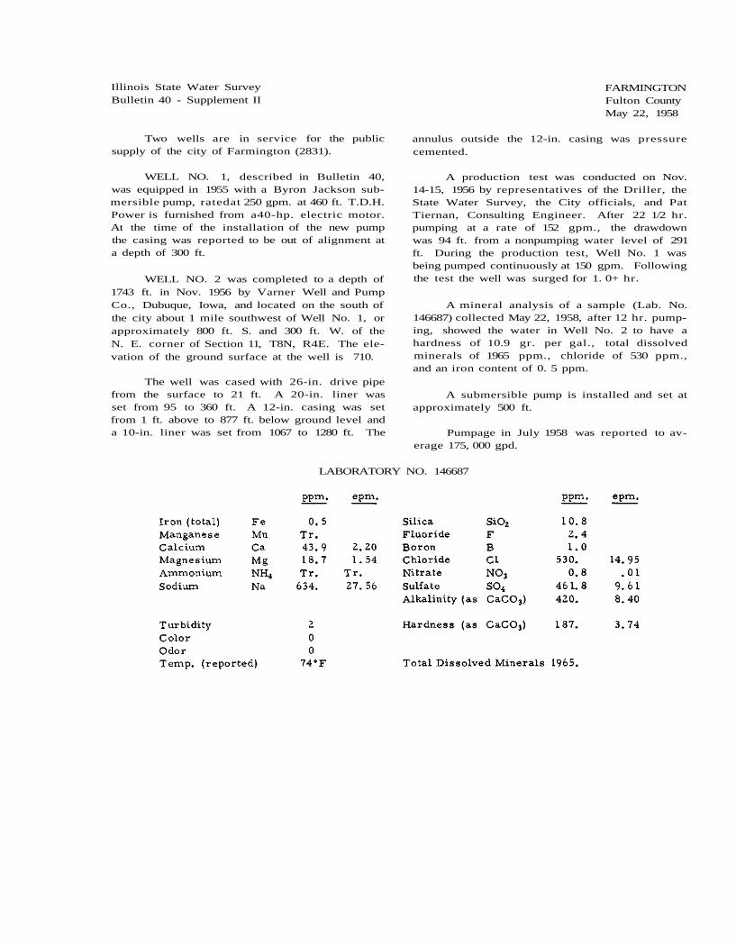
Illinois State Water Survey Bulletin 40 - Supplement II
FARMINGTON Fulton County May 22, 1958
Two wells are in service for the public supply of the city of Farmington (2831).
WELL NO. 1, described in Bulletin 40, was equipped in 1955 with a Byron Jackson sub-mersible pump, ratedat 250 gpm. at 460 ft. T.D.H. Power is furnished from a40-hp. electric motor. At the time of the installation of the new pump the casing was reported to be out of alignment at a depth of 300 ft.
WELL NO. 2 was completed to a depth of 1743 ft. in Nov. 1956 by Varner Well and Pump Co., Dubuque, Iowa, and located on the south of the city about 1 mile southwest of Well No. 1, or approximately 800 ft. S. and 300 ft. W. of the N. E. corner of Section 11, T8N, R4E. The ele-vation of the ground surface at the well is 710.
The well was cased with 26-in. drive pipe from the surface to 21 ft. A 20-in. liner was set from 95 to 360 ft. A 12-in. casing was set from 1 ft. above to 877 ft. below ground level and a 10-in. liner was set from 1067 to 1280 ft. The
annulus outside the 12-in. casing was pressure cemented.
A production test was conducted on Nov. 14-15, 1956 by representatives of the Driller, the State Water Survey, the City officials, and Pat Tiernan, Consulting Engineer. After 22 1/2 hr. pumping at a rate of 152 gpm., the drawdown was 94 ft. from a nonpumping water level of 291 ft. During the production test, Well No. 1 was being pumped continuously at 150 gpm. Following the test the well was surged for 1. 0+ hr.
A mineral analysis of a sample (Lab. No. 146687) collected May 22, 1958, after 12 hr. pump-ing, showed the water in Well No. 2 to have a hardness of 10.9 gr. per gal., total dissolved minerals of 1965 ppm., chloride of 530 ppm., and an iron content of 0. 5 ppm.
A submersible pump is installed and set at approximately 500 ft.
Pumpage in July 1958 was reported to av-erage 175, 000 gpd.
LABORATORY NO. 146687

Illinois State Water Survey Bulletin 40 - Supplement II
FERNWAY SUBDIVISION Cook County April 11, 1960
A public water supply was installed in 1959 for the Fernway Subdivision (est. 750) owned and operated by Citizens Utilities Co. of Illinois. The subdivision is located about 2 miles south-east of Orland Park.
WELL NO. 1 was completed in Feb. 1959 to a depth of 125 ft. by J. P. Miller Artesian Well Co., Brookfield, and located near 88th Ave. and 161st St., or approximately 2700 ft. S. and 1200 ft. W. of the N. E. corner of Section 22, T36N, R12E. The ground surface elevation at the well is 710.
The well was cased with 10-in. black steel pipe from 18 in. above L.S.D. to limestone at 118 ft., below which the hole was finished 10 in. in diameter.
When the well was completed in Feb. 1959 the Driller reported pumping for 6 hr. at a rate
of 400 gpm. with a drawdown of 7 ft. from a static water level of 38 ft. below the top of the casing.
A mineral analysis of a sample (Lab. No. 152020) collected Apr. 11, 1960 showed the water in Well No. 1 to have a hardness of 10. 1 gr. per gal., total dissolved minerals of 695 ppm., and an iron content of 0. 5 ppm. Apparently the wa-ter was zeolite softened and blended with raw water.
The pumping equipment consists of 80 ft. of 6-in. column pipe; 10-in., 6-stage Peerless turbine pump rated at 500 gpm., connected to a 40-hp. U S electric motor.
There are 212 services, all metered and all population served. Pumpage is estimated to average 35,000 gpd.
LABORATORY NO. 152020

Illinois State Water Survey Bulletin 40 - Supplement II
FLOSSMOOR Cook County November 19, 1958
Five wells are in service for the village of Flossmoor (4624).
No changes are reported for WELL NO. 1.
It is reported that a Byron Jackson sub-mersible pump, No. 297907, rated at 400 gpm., was in place in WELL NO. 2 (Park) attached to 150 ft. of 8-in. column pipe. An air line 150 ft. long was in place and power was furnished by a 30-hp. electric motor. On Dec. 17, 1957 the nonpumping water level was reported to be 48 ft.
No changes in WELL NO. 3 (Garage) have been reported. On Dec. 17, 1957 the nonpumping water level was reported to be 59 ft.
WELL NO. 4 was drilled in Sept. 1952 to a depth of 250 ft. by Layne-Western Co., Aurora, and located 850 ft. N. and 1650 ft. W. of the S. E. corner of Section 12, T35N, R13E. The ground elevation at the well is 653.
The well was cased with 12-in. gwi. pipe to a depth of 42 ft. 9 in., below which the open hole was finished 12 in. in diameter to the bottom at 250 ft. Ina production test by the Driller dur-ing the last week of Sept. 1952 "when pumping at a rate of 544 gpm., the drawdown was 52 ft. from a static water level of 7 ft. below the ground surface. "
The pumping equipment includes 130 ft. of 6-in. column pipe; 9 l/2-in., 7-stage Peerless turbine pump, No. 105725, rated at 475 gpm. and having an over-all length of 5 ft. 8 1/8 in.; 10 ft. of 6-in. suction pipe; 130 ft. of air line; 50-hp. U S electric motor. A Peerless right angle drive, No. J21274, is installed.
On Dec. 17, 1957 the nonpumping water level was 50 ft.
A mineral analysis of a sample (Lab. No. 148252) collected Nov. 11, 1958 showed the water in Well No. 4 to have a hardness of 38. 4 gr. per gal., total dissolved minerals of 890 ppm., and an iron content of 1. 5 ppm.
WELL NO. 5 was completed in Oct. 1956 to a depth of 501 ft. by Wehling Well Works, Beecher, and located 1961 ft. S. and 367 ft. E. of the N. W. corner of Section 12. The well was cased to 91 ft. with 12-in. wi. pipe. Rock was reportedly penetrated at 84 ft. From 92 ft. to the bottom at 501 ft. the hole was finished 11 1/2 in. in diameter.
In a production test reported by the Driller in Oct. 1956 water was pumped for 7 hr. at a rate of 450 gpm. with a drawdown of 47 ft. from a nonpumping water level of 40 ft. below the ground surface (691).
The pumping equipment includes 160 ft. of 6-in. column pipe; 10-in., 6-stage Fairbanks-Morse Pomona turbine pump, No. AW2501, rated at 450 gpm. against 212 ft. T.D.H.; 160 ft. of air line; 40-hp. Fairbanks-Morse electric motor.
Analysis of a sample (Lab. No. 147271) collected July 17, 1958, after 7 hr. pumping at 320 gpm., showed the water in Well No. 5 to have a hardness of 41.4 gr. per gal., total dis-solved minerals of 994 ppm., and an iron con-tent of 0. 2 ppm.
Pumpage for 1956 was reported to average 400,000 gpd.
LABORATORY NO. 147271

2 - Flossmoor
LABORATORY NO. 148252

Illinois State Water Survey Bulletin 40 - Supplement II
FOREST HOMES - MAPLE PARK PUBLIC WATER DISTRICT Madison County January 19, 1960
A public water supply was installed in Jan. 1960 for the Forest Homes-Maple Park Pub-lic Water District (est. 450) located about 1 mile west of Bethalto.
WELL NO. 1 was completed in Nov. 1959 to a depth of 67 ft. by Layne-Wes tern Co., Kirkwood, Mo., and located about 175 ft. east of the East Fork of Wood River about 1 mile northeast of the Water District, or approximately 675 ft. S. and 2600 ft. W. of the N. E. corner of Section 2, T5N, R9W. The ground surface elevation at the well is 450. The hole was drilled 20 in. in diameter from top to bottom. The well was cased with 24-in. pipe to a depth of 8 ft. and 10-in. pipe from 1 ft. above the surface to 54 1/2 ft. followed by 20 ft. of Layne stainless steel No. 5, shutter type, screen. Five tons of torpedo gravel were packed in the annulus between the 10-in. casing and screen and the wall of the hole.
A production test was conducted on Nov. 9, 1959 by representatives of the Driller, the State Water Survey, and Clifford Abraham, Consulting Engineer. For the test a Johnston turbine test pump, 3. 5 ft. long, was attached to 46 ft. of col-umn pipe. Ten ft. of suction pipe was installed and power was from a gas engine. Water level measurements were made by tape. After 4 hr. pumping at 150 gpm., the drawdown was 46 ft. below a static water level of 12. 9 ft. below the top of the casing. Or.e hr. after the pump was stopped, the water level had recovered to 17.4 ft. Pumping was then resumed at 140 gpm. and after 3 hr. the drawdown was 28 ft. Fifteen min. after the pump was stopped, the water level had recovered to 20. 9 ft. and at 14 hr. the water level was 14.1 ft. below the top of the casing.
A partial chemical analysis of a sample (Lab. No. 150976) collected Nov. 9, 1959, after 4 hr. pumping at a rate of 150 gpm., showed the water in Well No. 1 to have a hardness of 12. 4 gr. per gal., total dissolved minerals of 294 ppm., turbidity of 86 ppm., and an iron content of 12 ppm.
WELL NO. 2 was completed in Jan. 1960 to a depth of 66 ft. by Layne-Western Co. and located about 180 ft. east of East Fork, 100 ft. southwest of Well No. 1, or approximately 773 ft. S. and 2620 ft. W. of the N. E. corner of Section 2. The hole was drilled 20 in. in diam-eter from top to bottom and cased with 10-in. pipe from 1 ft. above the surface to 46 ft. fol-
lowed by 20 ft. of Layne No. 5 shutter screen.
A production test was conducted on Jan. 19, 1960 by representatives of the Driller, the State Water Survey, and Village officials. For the test the pumping equipment included a Johnston turbine pump, 3. 5 ft. long, attached to 46 ft. of column pipe and with 10 ft. of suction pipe. Power was furnished by a gasoline engine. Water level measurements were made with a steel tape. Aft-er 4 hr. pumping at a rate of 111 gpm., the draw-down was 16. 7 ft. from a static water level of 12.1 ft, below the top of the casing. Pumping was stopped to observe the recovery of water level in Well No. 2. After 1 hr. the water level had recovered to 14. 8 ft. Pumping was resumed at a rate of 122 gpm. for 15 min., followed by 15 min. pumping at 130 gpm., and for an additional 15 min. pumping at 146 gpm., at the end of which the final drawdown was 20 ft. Pumping was then continued at a rate of 111 gpm. and after 3 hr. the drawdown was 16.6 ft. below the original static level of 12. 1 ft. below the top of the casing. Fif-teen min. after the pump was stopped, the water level had recovered to 17 ft. and 14 1/2 hr. later the water level was 12. 7 ft.
During the pumping in Well No. 2 water levels were observed (by tape) in Well No. 1. At the end of the 1 hr. recovery after the first pump-ing at 111 gpm. in Well No. 2 the water level in Well No. 1 recovered 4 ft. from a low of 19.1 ft. below a static level of 12, 3 ft. At the end of pump-ing in Well No. 2 the water level in Well No. 1 had lowered to 6.5 ft. below the static level of 12. 3 ft. At the end of 14 l/2 hr. recovery period the water level in Well No. 1 had raised to 12. 9 ft.
In each well at the end of 14 1/2 hr. the water level had recovered to 0. 6 ft. of the initial static level.
A partial chemical analysis of a sample (Lab. No. 151498) collected Jan. 19, 1960, after 8 hr, pumping at rates of 111 to 146 gpm., showed the water in Well No. 2 to have a hardness of 14.1 gr, per gal., total dissolved minerals of 291 ppm., turbidity of 100 ppm., and an iron con-tent of 12 ppm.
The permanent pumping equipment has not been installed and pumpage is not being recorded. Requirement for 450 persons is estimated to av-erage 27, 000 gpd.

2 - Forest Homes - Maple Park Public Water District
LABORATORY NO. 151498

Illinois State Water Survey Bulletin 40 - Supplement II
FOREST LAKE ADDITION Lake County December 4, 1959
A public water supply was installed in 1939 for the Forest Lake Addition (est. 160), an unin-corporated subdivision located about 2 miles northeast of Lake Zurich and about 6 miles south-west of Mundelein. The system is owned and operated by Henry Boysen, Liber tyville.
WELL NO. 1 was completed in 1939 to a depth of 240 ft. by Henry Boysen and located at the southeast corner of Arbor Lane and Lakeside Drive, or approximately 600 ft. N. and 1900 ft. W. of the S. E. corner of Section 10, T43N, R10E. The ground surface elevation at the well is 810.
The well was cased with 6-in. pipe from the surface to 211 ft. (limestone), below which the hole was finished 6 in. in diameter. When the well was completed in 1939 the Driller reported pumping at a rate of 40 gpm. for 7 hr . The static water level was 42 ft. below the surface but the drawdown was not reported.
The pumping equipment includes a Deming turbine pump connected to a 5-hp. U S electric motor.
Pumpage is estimated to average 12, 000 gpd.

Illinois State Water Survey Bulletin 40 - Supplement II
FORRESTON Ogle County October 10, 1960
One well furnishes the public water supply of the village of Forreston (1153).
WELL NO. 1, described in Bulletin 40, is now maintained for stand-by use only. A new Johnston turbine pump was installed in 1952. The pump is rated at 200 gpm. and connected to a 20-hp. U S electric motor. An Amarillo right angle drive is mounted with power to be supplied by a tractor stationed outside of the building.
WELL NO. 2 was completed in Nov. 1952 to a depth of 1000 ft. by Neely and Schimelpfenig, Batavia, and located in the southeast part of town south of Well No. 1, or approximately 2370 ft. S. and 2030 ft. W. of the N. E. corner of Section 33, T25N, R8E. The ground surface elevation at the well is 920. The well was cased with 43 ft. of surface pipe and 12-in. pipe from the surface to 254 ft. (grouted in) followed by a 12-in. hole from 254 to 455 ft. A 10-in. liner was set from 455 to 590 ft. followed by a 10-in. hole from 590 to 760 ft. An 8-in. liner was set from 760 to 840 ft. followed by an 8-in. hole from
840 to the bottom at 1000 ft.
A production test was conducted by the Driller on Nov. 3, 1952. After 9 hr. pumping at 455 gpm., the drawdown was 28 ft. from a nonpumping water level of 158 ft. below the ground surface.
Layne-Western Co. installed the perma-nent pump assembly consisting of 220 ft. of 6-in. column pipe; 10-in., 9-stage Layne turbine pump, No. 25185, rated at 400 gpm.; 220 ft. of gi. pipe air line; 10 ft. of 6-in. suction pipe; 40-hp. elec-tric motor,
A mineral analysis of a sample (Lab. No. 153353) collected Oct. 6, 1960, after 15 min. pumping at a rate of 400 gpm., showed the water to have a hardness of 17.2 gr. per gal., total dissolved minerals of 286 ppm., and an iron con-tent of 0. 4 ppm.
Pumpage for the village in 1958 averaged 150,000 gpd.
LABORATORY NO. 153353

2 - Forreston
Sample study summary log of WELL NO. 2 furnished by the State Geological Survey

Illinois State Water Survey Bulletin 40 - Supplement II
FOX RIDGE STATE PARK Coles County May 6, 1959
Fox Ridge State Park WELL NO. 1 was . completed in Mar. 1938 to a depth of 157 ft. by-Ed Piercy, Charleston, and located approximate-ly 1380 ft. S. and 1800 ft. E. of the N. W. cor-ner of Section 13, T11N, R9E. The ground sur-face elevation at the well is 670 to 685. The well was cased with 6-in. pipe to an unknown depth. The hole was finished 6 in. in diameter.
The well was equipped with a Fairbanks-Morse plunger pump, rated at 400 gal. per hr. with the 30-in. cylinder set at 145 ft. The pump had a 9-in. stroke. Power was furnished by an electric motor and also a gas engine. In 1941, after 5 3/4 hr. pumping at a rate of 20 gpm., the drawdown was 44 ft. from a static water lev-el of 32 ft.
A mineral analysis of a sample (Lab. No. 97301) collected Aug. 31, 1943, after 5 min. pumping at 5 gpm., showed the water in Well No. 1 to have a hardness of 4. 6 gr. per gal., total dissolved minerals of 575 ppm., and an iron content of 1 ppm.
Well No. 1 (Test Well No. 1-54) was com-pleted in Mar. 1954 by the Driller and observed by representatives of the State Division of Archi-tecture and Engineering and the State Water Sur-vey. For test purposes a 15-stage Fairbanks-Morse submersible rated at 23 1/2 gpm. was in place with the bottom of the suction set at 157 ft. Power was furnished by a 1-hp. electric motor. The old park well nearby was used to observe water levels. After 24 hr. pumping at 29 ppm., the drawdown was 35.8 ft. from a nonpumping water level of 122. 3 ft. below the top of the cas-ing. -During the pumping period the water level in the observation well was lowered 8. 3 ft. from a static water level of 122. 2 ft.
A mineral analysis of a sample (Lab. No. 149506) collected Apr. 30, 1959 showed the water in Test Well No. A 1-54 (formerly 1-54) to have a hardness of 4 gr. per gal., total dissolved minerals of 562 ppm., and an iron content of 3.1 ppm.
The yield of the test well was not suffi-ciently adequate to warrant development.
On May 6, 1959 it was reported that Well No. 1 is equipped with a Jacuzzi jet pump with a Century 1 l/2-hp. electric motor.
WELL NO. 2 (Test Well No. 2-54) was completed in Apr. 1954 to a depth of 221. 5 ft. by E. C. Baker and Sons, Sigel, and located on the east side of the park, or approximately 1300 ft. S. and 700 ft. E. of the N. W. corner of Section 18, T11N, R10E. The ground surface elevation at the well is 720. The well was cased with 8-in. pipe from 2. 5 ft. above ground level to 212 ft. followed by 9. 5 ft. of screen with . 015-in. slot openings.
Sample study summary log of WELL NO. 2-54 furnished by the State Geological Survey
A production test was conducted on May 18-19, 1954 on Test Well No. 2-54 by the Driller. For the test a submersible test pump was in-stalled with power furnished from an electric motor. After 24 hr. pumping at a rate of 5 gpm., the drawdown was 58. 4 ft. from a nonpumping water level of 136.8 ft. below the top of the casing.
A partial analysis of a sample (Lab. No. 134864) collected May 18, 1954 showed the water in Test Well No. 2-54 to have a hardness of 13. 8 gr. per gal., total dissolved minerals of 400 ppm., and an iron content of 1. 9 ppm.

2 - Fox Ridge State Park
LABORATORY NO. 149506
LABORATORY NO. 134864

Illinois State Water Survey Bulletin 40 - Supplement II
FOX RIVER GROVE McHenry County October 9, 1958
Two wells are in service for the public water supply of the village of Fox River Grove (1866).
WELL NO. 1 is described in Bulletin 40.
WELL NO. 2 was completed in 1956 to a depth of 120 ft. by Layne-Western Co. , Aurora, and located about 160 ft. northeast of Well No. 1, or approximately 250 ft. N. and 1100 ft. W. of the S. E. corner of Section 18, T43N, R9E. The ground surface elevation at the well is 740. The well was cased with 10-in. steel pipe with welded joints from 3 ft. above to 101 ft. below the surface. From 101 to 120 ft. the hole was finished at 10 in. in diameter.
When the well was finished in Sept. 1956, the Driller reported pumping for 9 hr . at a rate of 320 gpm. with a drawdown of 35 ft. from a static water level of 17 ft. below the top of the casing. The length of the test was 20 hr.
The pumping equipment consists of 80 ft. of 5-in. column pipe; 8-in., 8-stage Layne turbine pump (No. 36028), 5 ft. 8 in. long, and rated at 300 gpm.; 10 ft. of 6-in. suction pipe; 82 ft. of air line; 20-hp. U S electric motor.
On Apr. 10, 1958, when pumping at capacity, the drawdown was 23 ft. from a nonpumping water level of 9 ft.
A mineral analysis of a sample (Lab. No. 146280) collected Apr. 11, 1958 showed the water in Well No. 2 to have a hardness of 21. 8 gr. per gal . , total dissolved minerals of 433 ppm., and an iron content of 2.1 ppm.
Meters were installed in Apr. 1958 and pumpage for May, June, and July 1958 averaged 146,160 gpd.
Sample study summary log of WELL NO. 2 fur-nished by the State Geological Survey
LABORATORY NO. 146280

Illinois State Water Survey Bulletin 40 - Supplement II
GALESBURG Knox County January 10, 1961
One collector well is in service for the city of Galesburg (37, 243). Prior to the construction of this well, the Galesburg water supply was ob-tained from five rock wells. These are being maintained for emergency service.
WELL NO. 1 (Collector) was constructed by Ranney Method Water Supplies, Inc. and plac-ed in service in May 1959. In 1956 a number of test holes were drilled by Layne-Western Co., Aurora, in the Mississippi River alluvium near Oquawka in Henderson County. The collector was located at the site of Test Well No. AW-2 on the south side of the village, less than 100 ft. from the river bank, or approximately 1540 ft. S. and 4480 ft. W. of the N. E. corner of Section 22, T11N, R5W. A 13-ft. id. by 16-ft. od. re-inforced concrete caisson was constructed to a depth of 97 ft. below a ground surface elevation of 528. The inside depth of the collector is 108.25 ft. below the elevation of the top (539.25). Nine 12-in. diameter perforated steel pipe laterals project radially from the collector at elevation 438. The total lineal length of the laterals is 1800 ft. distributed as shown in Table A.
A partial chemical analysis of a sample (Lab. No. 145738), after 84 hr. pumping at a rate of 5700 gpm., showed the water to have a
hardness of 10.9 gr. per gal., total dissolved minerals of 210 ppm., and an iron content of 0.5 ppm.
TABLE A
The collector well is equipped with 24-in. Byron Jackson, type KXL pumps, rated at 5000 gpm. at 400 ft. T.D.H. and 600-hp., 2400-volt electric motor.
Water is pumped 30. 5 miles to Galesburg, through a prestressed concrete pipe line (25.3 miles of 36-in. diameter pipe and 5. 2 miles of 42-in. pipe) and discharged into a 5-mg. ground storage reservoir located at the Main St. station.
Pumpage is reported to average 6.00 mgd.
LABORATORY NO. 145738

Illinois State Water Survey Bulletin 40 - Supplement II
GARY AVENUE GARDENS DuPage County October 30, 1958
A public water supply was installed in 1929 for Gary Avenue Gardens (est. 200), a subdivision located north of Wheaton. The system is owned by Mrs. Elizabeth Bird.
WELL NO. 1 was completed in 1929 to a depth of 200 ft., reportedly by a Driller from Batavia, and located at the southeast corner of Gary and Doris St., or approximately 2550 ft. N. and 2550 ft. W. of the N. E. corner of Section 5, T39N, R10E. The ground elevation at the well is 770.
The well is cased with 4-in. pipe to an un-
reported depth. The pumping equipment includes 60 ft. of 2 l/2-in. column pipe; Pomona turbine pump, No. AH54181, rated at 45 gpm. against 60 ft. T.D.H.; 3-hp. Fairbanks-Morse electric motor.
A partial chemical analysis of a sample (Lab. No. 148125) collected Oct. 30, 1958 showed the water in Well No. 1 to have a hardness of 17.1 gr. per gal., total dissolved minerals of 340 ppm., and an iron content of 0. 2 ppm.
Pumpage in Oct. 1957 was estimated to average 17,500 gpd.
LABORATORY NO. 148125

Illinois State Water Survey Bulletin 40 - Supplement II
GERMANTOWN Clinton County January 13, 1958
Water for the village of Germantown (983) is obtained from three gravel packed wells. The dug well, reported in Bulletin 40, was deepened in 1954 by placing a 36-in. vitreous tile from the bottom of the dug portion to a depth of 30 ft. The well is no longer in service but is maintained for fire protection.
A well was drilled in Oct. 1955 to a depth of 223 ft. by Layne-Western Co., Aurora, and located about 200 ft. southeast of the old dug well. The well was cased with 8-in. pipe to 88 ft. A production test was conducted on Oct. 27 by rep-resentatives of the Driller and the State Water Survey. After 1 3/4 hr. pumping at a rate of 5 gpm., the drawdown was 129 ft. from a nonpump-ing water level of 33 ft. below the top of the cas-ing.
An analysis of a sample (Lab. No. 138930) showed the water to have a hardness of 3. 3 gr. per gal., total dissolved minerals of 876 ppm., chloride of 162 ppm., and an iron content of 27 ppm. The turbidity was 850 ppm.
A short production test of the old dug well was conducted on Nov. 3, 1955 by representatives of J. Paul Rhoads, Consulting Engineer, and the State Water Survey. After 58 min. pumping at a rate of 41. 6 gpm., the drawdown was 5. 6 ft. from a nonpumping water level of 13 ft. below the top of the well. During the last 10 min. of pumping the rate fluctuated. Water level readings, after the level had fallen below the top of the tile, were made in the outer diameter of the well.
Several test holes were drilled under the supervision of J. Paul Rhoads, Engineer, in an attempt to obtain a minimum water supply of 80 gpm. for the. village. Subsequently, Wells 1, 2 and 3 were drilled by Layne-Western Co., Aurora.
WELL NO. 1 was located on the west side of Green St. and 40 ft. south of the center line of the Southern Railroad right-of-way, or approxi-mately 1250 ft. N. and 2300 ft. W. of the S. E. corner of Section 4, T1N, R4W. The hole was bored 30 in. in diameter and cased with 8-in. steel pipe to 21 ft. 5 1/2 in. followed by 5 ft. of Layne shutter-type screen to 26 ft. 5 1/2 in. be-low the top of the casing which was left 1 ft. 6 in. above the ground surface. The annulus outside the screen and casing was backfilled with gravel up to about 14 ft. above the bottom of the well.
A production test was conducted on Jan. 18, 1956 by representatives of the Driller, the Consulting Engineer, and the State Water Survey. After 5 hr. 20 min. pumping at a rate of 47 gpm., the drawdown was 4. 9 ft. from a nonpumping water level of 15. 5 ft. below the top of the casing. Fifteen min. after pumping was stopped, the wa-ter level had recovered to 16. 5 ft.
Analysis of a sample (Lab. No. 145463) col-lected Jan. 9, 1958, after 5 min. pumping at 40 gpm., showed the water in Well No. 1 to have a hardness of 17.9 gr. per gal., total dissolved minerals of 465 ppm., and a trace of iron.
The permanent pump installation includes 19 ft. of column pipe; 5 5/8-in., 10-stage Layne turbine pump, Factory No. 34263, having an over-all length of 4 ft. 11 in. and rated at 35 gpm.; 20 ft. of air line; 3-hp. U S electric motor.
WELL NO. 2 was constructed similar to Well No. 1 and located 318 ft. west of Well No. 1. The 8-in. casing and 5 ft. of No. 5 gage Layne screen were set in a 30-in. hole with the bottom of the screen at 26 ft. 8 in. below the top of the casing which was left 1 ft. 8 in. above the ground level. The well was backfilled with gravel up to 14 ft. A production test was conducted on Jan. 25, 1956. After 8 hr. pumping at a rate of 42 gpm., the drawdown was 4 ft. 5 in. from a non-pumping water level of 15 ft. 8 in. below the top of the casing. Nine min. after pumping was stop-ped, the water level had recovered to 16 ft. 10 in. During the test the water level in Well No. 1 was lowered 3 1/4 in.
The permanent pump assembly in Well No. 2 is identical with the installation in Well No. 1.
WELL NO. 3 was constructed similar to Wells 1 and 2, and located 316 ft. west of Well No. 2, or approximately 1250 ft. N. and 2934 ft. W. of the S. E. corner of Section 4. The 8-in. casing and 5 ft. of No. 5 gage Layne screen were set in a 30-in. hole with the bottom of the screen at 28. 5 ft. and the top of the casing at 1. 2 ft. above the ground surface. The well was backfilled with gravel up to 14 ft.
A production test was conducted on Feb. 1, 1956. After 8 hr. pumping at 45 gpm., the draw-down in Well No. 3 was 9 ft. from a nonpumping water level of 18.1 ft. below the top of the casing.

2 - Germantown
Seven min. after pumping was stopped, the water level had recovered to 19.7 ft.
The permanent pump assembly in Well No. 3 is reported to be identical with that in Wells No. 1 and 2.
A partial analysis of a sample (Lab. No. 139706) collected Feb. 1, 1956, after 4 1/2 hr. pumping at 38 gpm., showed the water in Well No. 3 to have a hardness of 19. 2 gr. per gal., total dissolved minerals of 369 ppm., and an iron content of 1 ppm.
Pumpage is reported to average 6000 gpd.
Correlated driller's log of WELL NO. 3 furnish-ed by the State Geological Survey
LABORATORY NO. 145463

Illinois State Water Survey Bulletin 40 - Supplement II
GILMAN Iroquois County September 9, 1960
Water for the public supply of the city of Gilman (1704) is principally obtained from one 12-in. well with two older wells in service for supplemental supply.
Subsequent to the construction of the 5-in. well by Lowell French, Ashkum, described in Bulletin 40, a production test was conducted on June 8, 1950 by representatives of the Driller, the City, the State Geological Survey, and the State Water Survey. After 3/4 hr. pumping at a rate of 63 gpm., the drawdown was 24.3 ft. from a static water level of 0. 95 ft. below the top of the casing. Ten min. after pumping was stopped, the water level had recovered to 1.1 ft. Before the start of pumping, the natural flow of the 5-in. well was measured in the smaller one of the two ground storage reservoirs near the well. The natural flow was 12 gprm.
The natural flow of the south 6-in. well, described in Bulletin 40, was measured at the same time and while the air lift was idle. The flow rate from the 6-in. well was 14 gpm.
The free flow of the 5-in. well was appar-ently insufficient and the well was equipped with an air pipe, an air compressor, and a 1 l/2-hp. electric motor.
The north 8-in. well, described in Bulletin 40, was deepened to 191 ft. in late 1950 by a Mr. Hutchens of Gilman. A 6-in. casing was set from the bottom of the 8-in. casing to the bottom of the well at 191 ft. The lower 2 ft. of 6-in. pipe was perforated.
This well was reported in 1951 to be free flowing with discharge into the main reservoir. However, a 210-gpm. Fairbanks-Morse centrif-ugal pump was installed for pumping the well. Power for pumping was from a 5-hp. electric motor.
In July 1952, WELL NO. '52 was completed to a depth of 195 ft. by J. Bolliger and Sons, Fairbury, and located at the southwest corner of the intersection of Maple and Crescent St., about 400 ft. east of the water works, or approx-imately 100 ft. S. and 2570 ft. E. of the N. W. corner of Section 6, T26N, R14W. The ground surface elevation at the well is 654. The well was cased with 181 ft. of 12-in. steel (49 lb./ft. ) pipe, from 2. 5 ft. above ground level, followed by a 16 ft. length of 5-in. Houston stainless steel screen. The joints in the upper 114 ft. of casing
were screw coupled and in the lower 67 ft. were welded. The screen had No. 14 slot openings at the top and No. 16 slots at the bottom.
Correlated driller's log of WELL NO. '52 fur-nished by the State Geological Survey
A production test was conducted on Well No. '52 on Aug. 20, 1952 by representatives of the Driller, the City officials, the State Water Survey, and Warren and VanPraag, Inc., Con-sulting Engineers. For test purposes, the well was equipped with a Peerless turbine pump set at 65 ft. below the top of the casing. Power for pumping was furnished by a right angle gear drive from a Mercury V-8 gasoline engine. After 5 hr. pumping at a rate of 302 gpm., the draw-down was 22 ft. from a static water level at the top of the casing. For the next 3/4 hr. the pump-ing rate was stepped up to 482 gpm. with a total drawdown of 37 ft. Twenty-two min. after pump-ing was stopped, the water level had recovered to 3. 2 ft.
A complete mineral analysis of a sample (Lab. No. 129689) collected Aug. 20, 1952, after 4 1/2 hr. pumping at 300 gpm., showed the water in Well No. '52 to have a hardness of 35. 2 gr. per gal., total dissolved minerals of 964 pprn., and an iron content of 2. 4 ppm.
Well No. '52 is equipped with a Layne tur-bine pump, rated at 300 gpm., connected to a

2 - Gilman
10-hp. U S electric motor. Water is discharged from the well to the aerator at the treatment plant.
The Well No. '52 is the principal source of supply. Water is pumped only from the col-lecting reservoir, which receives the free flow from the smaller wells when the water level in the reservoir reaches the overflow load.
At times the static water level in Well No. '52 rises to the surface. The free flow then dis-charges through a vent pipe in the top of the cas-ing.
WELL NO. 8 (in the order of drilling) was completed in Sept. 1960 to a depth of 197 ft. by J. Bolliger and Sons and located about 500 ft. west of Well No. 7 ('52), or approximately 100 ft. S. and 2100 ft. E. of the N. W. corner of Section 6. The ground surface elevation at the well is 654.
The well was cased with 12-in. pipe from 3 ft. above to 185 ft. below the surface followed by a 12-in. Johnson stainless steel screen to 197 ft. The lower 4 ft. of screen had No. 20 slot open-ings, the middle 4 ft. had No. 18 slots, and the upper 4 ft. had No. 15 slots.
A production test was conducted on Sept. 9, 1960 by representatives of the Driller, the State Water Survey, and Vail Moore, Consulting Engi-neer. For test purposes an 8-in., 8-stage Po-mona test turbine, 10 ft. long, was set at 85 ft. The base of the pump was 4 ft. above the ground surface. A gas engine furnished the power for pumping. After 5 l/2 hr. pumping at a constant rate of 280 gpm., the drawdown was 37. 4 ft. from a nonpumping water level of 4.1 ft. below the pump base.
Pumping was then continued at 190 gpm. and after 15 min. the drawdown was 24. 5 ft.
Then after 15 min. pumping at 165 gpm., the drawdown remained steady at 21.4 ft.
A partial chemical analysis of a sample (Lab. No. 153207) collected Sept. 9, 1960, after 4 hr. pumping at 280 gpm., showed the water in Well No. 8 to have a hardness of 35. 4 gr. per gal., total dissolved minerals of 993 ppm., and an iron content of 2. 3 ppm.
There are 600 services not metered.
Pumpage for 1956 was reported to average 100,000 gpd.
LABORATORY NO. 129689

Illinois State Water Survey Bulletin 40 - Supplement II
GLEN CARBON Madison County July 20, 1959
One well is in service for the public water supply of the village of Glen Carbon (1241).
WELL NO. 1, described in Bulletin 40, was acidizedinl953 by Harold Watson, East St. Louis. New pumping equipment was installed due to corrosion of parts. The well was subsequently abandoned in 1956 and was to be filled and sealed.
WELL NO. 2 was completed in Nov. 1951 to a depth of 66 ft. 3 in. by Harold Watson and lo-cated on the north side of Route 162, about 150 ft. north of Well No. 1, or approximately 1650 ft. S. and 4500 ft. E. of the N. W. corner of Section 5, T3N, R8W. The elevation of the ground sur-face at the well is 440. The well was cased with 46 ft. of 12-in. pipe from 1 ft. above the ground level to approximately 45 ft. below followed by 21 ft. 7 in. of 12-in. Cook screen. The upper part of the screen had No. 14 slot openings and the lower part had No. 25 slots.
A production test was conducted on Nov. 2, 1951 by representatives of the Driller, the State Water Survey, and Village officials. For test purposes the well was equipped with a Cook tur-bine pump set at 50 ft. below the top of the cas-ing. After 24 hr. pumping at a rate of 98 gpm., the drawdown was 13. 6 ft. from a static water level of 22. 2 ft. below the top of the casing. One and one-half hr. after the pump was stopped, the water level had recovered to 23 ft.
A mineral analysis of a sample (Lab. No. 126915) collected Nov. 3, 1951, after 24 hr. pump-ing at a rate of 98 gpm., showed the water in Well No. 2 to have a hardness of 27. 7 gr. per gal., total dissolved minerals of 590 ppm., and an iron content of 0. 9 ppm.
The pumping equipment consists of 40 ft. of column pipe; Cook turbine pump (No. 13284); 10 ft. of 4-in. suction pipe; 3-hp. U S electric motor.
Since July 1959 Well No. 2 has been main-tained for emergency use only.
WELL NO. 3 (Peters Station) was com-pleted in May 1956 to a depth of 62 ft. by Thorpe Concrete Well Co., Alton, and located about 230 ft. west of Well No. 1, or approximately 1800 ft. S. and 4220 ft. E. of the N. W. corner of Sec-tion 5. The elevation of the ground surface at the well is 398. The well was cased with 12 ft. of 40-in. od. by 30-in. id. blank concrete pipe followed by 48 ft. of porous concrete pipe screen. The top of the concrete pipe is 3/4 ft. above L. S.D.
A production test was conducted on Dec. 6, 1956 by representatives of the Driller, the State Water Survey, and Sheppard, Morgan and Schwaab, Consulting Engineers for the village. The per-manent pumping equipment was in place for the test. After 3/4 hr. pumping at a rate of 104 gpm., the drawdown was 7 ft. below a static water level of 30 ft. below the pump base. Due to the short air line, the drawdown for a higher pumping rate could not be measured. With the valve wide open the pumping rate fluctuated between 250 and 210 gpm. With the valve partially closed and pump-ing at about 232, there was little fluctuation.
The pumping equipment includes 41 ft. of 5-in. column pipe; 4-stage American Well Works turbine pump, 3 ft. in length and rated at 300 gpm. when pumping to discharge; 10 ft. of 5-in. suction pipe; 40 ft. of air line; 7 l/2-hp. U S electric motor.
mineral analysis of a sample (Lab. No. 146493) collected Apr. 28, 1958 showed the water in Well No. 3 to have a hardness of 30 gr. per gal., total dissolved minerals of 666 ppm., and an iron content of 0. 4 ppm.
In Jan. 1957 pumpage was reported to av-erage 35,000 gpd.

Z - Glen Carbon
LABORATORY NO. 146493

Illinois State Water Survey Bulletin 40 - Supplement II
GLENDALE ADDITION Rock Island County May 21, 1959
A public water supply was installed in 1955 for the Glendale F i r s t and Second Additions (est. 80), a subdivision located at Ninth St. and Colona Road, about 2 miles south of Silvis. The system is owned and operated by Glendale Improvement Association.
WELL NO. 1 was completed in 1955 to a depth of 595 ft. by Peerless Service Co., Orion, and located at the south end of Ninth St., 1 block south of Colona Road, or approximately 1065 ft. S. and 269 ft. W. of the N. E. corner of Section 7, T17N, R1E. The ground surface ele-vation at the well is 7.02.
The well was cased with 10-in. pipe from 1 ft. above to 227 ft. below the ground surface, followed by 8-in. pipe from 227 ft. to 318 ft. From 318 to 595 ft. the hole was finished 8 in. in diameter.
A production test was conducted onMay 19,
1959 by representatives of the Driller, the State Water Survey, and the Consulting Engineers, Missman, Stanley, Fa rmer & Associates. The permanent pumping equipment was in place and consisted of 443 ft. of column pipe; a Red Jacket submersible pump, rated at 150 gpm.; 443 ft. of air line; 20-hp. electric motor. After 5 hr. 40 min. pumping at 121 gprn., the drawdown was 219 ft. from a nonpumping water level of 162. 5 ft. below the top of the casing. One hr. after pump-ing was stopped, the water level had recovered to 175 ft.
A mineral analysis of a sample (Lab. No. 149637) collected May 19, 1959, after 6 hr. pump-ing at a rate of 125 gpm., showed the water in Well No. 1 to have a hardness of 14. 3 gr. per gal . , total dissolved minerals of 452 ppm., and an iron content of 1. I ppm. An odor of H2S was present.
Pumpage is estimated to average 5000 gpd.
LABORATORY NO. 149637

Illinois State Water Survey Bulletin 40 - Supplement II
GLEN ELLYN DuPage County July 6, 1959
Three wells furnish the water supply for the village of Glen Ellyn (15, 972).
WELL NO. 1, described in Bulletin 40, was abandoned several years ago.
WELL NO. 2, described in Bulletin 40, was equipped in Oct. 1956 with new pump bowls set at 270 ft. The static water level at the time was 72.1 ft. Also a new suction pipe and air line were installed. Well No. 2 is in serv-ice.
WELL NO. 3 is in service, without any change since Bulletin 40. In July 1957 Wells No. 2 and 3 furnished 14% of the total pumpage for the village.
A TEST WELL was drilled in Dec. 1953 to a depth of 418 ft. by Neely, Schimelpfenig and Neely, Batavia, and located in the southeast corner of the intersection of Newton Ave. and DuPage Blvd. in Glen Ellyn Manor Subdivision, or approximately 1040 ft. N. and 625 ft. W. of the S. E. corner of Section 15, T39N, R10E. The ground surface elevation at the well is 760. The test well was cased with 8-in. pipe to 138 ft,, below which the hole was finished at 8 in. in diameter.
A production test was conducted on Dec. 28, 1953 by representatives of the Driller, the State Water Survey, and Walter E. Deuchler Co., Aurora, Consulting Engineers. For test pur-poses the pumping equipment consisted of 200 ft. of 4-in. column pipe; 5 l/2-in., 8-stage Cook turbine test pump belt-driven from a stationary gasoline engine; 200 ft. of air line. After 4 hr. pumping at a rate of 228 gpm., the drawdown was 5 ft. from a nonpumping water level of 73 ft. After Well No. 4 was put into service, the Test Well was filled and abandoned.
WELL NO. 4 was completed in Feb. 1954
to a depth of 422 ft. by L. Cliff Neely, Batavia, and located about 200 ft. S. of the Test Well, or approximately 860 ft. N. and 645 ft. W. of the S. E. corner of Section 15. The ground sur-face elevation at the well is 760. The well was cased with 26-in. pipe from the surface to 20 ft. and with 20-in. pipe from 1.7 ft. above to 150 ft. below the ground surface.
A production test was conducted on Feb. 26, 1954 by representatives of the Driller, the Engineers, and the State Water Survey. For test purposes the pumping equipment consisted of 200 ft. of column pipe; a Peerless turbine test pump directly connected to a Buda gasoline engine. A 200-ft. air line was installed. After 21 hr. pumping at a rate of 995 gpm., the draw-down was 27 ft. from a nonpumping water level of 85 ft. below the top of the casing.
On Apr. 24, 1956 the pumping water level was 115 ft. and on July 9, 1957 the pumping level was 119 ft. In July and August 1957 the non-pumping water level fluctuated between 94 and 96.
The permanent pumping equipment in-stalled in Aug. 1954 consists of 160 ft. of 10-in. column pipe; 9 l/2-in., 9-stage Layne turbine pump, No. 27943, rated at 1350 gpm.; 10 ft. of 10-in. suction pipe; 174 1/2 ft. of air line; 100-hp. Westinghouse electric motor.
For July 1957, Well No. 4 furnished 86% of the total pumpage for the village.
A mineral analysis of a sample (Lab. No. 146388) collected Apr. 18, 1958, after 6 hr. pumping at 995 gpm., showed the water in Well No. 4 to have a hardness of 16. 5 gr. per gal., total dissolved minerals of 456 ppm., and an iron content of 0.5 ppm.
Total pumpage for the village for Jan. to June 1959 inclusive averaged 1.20 mgd.

2 - Glen Ellyn
LABORATORY NO. 146388

Illinois State Water Survey Bulletin 40 - Supplement II
GLEN ELLYN HEIGHTS SUBDIVISION DuPage County August 15, 1960
A public water supply was installed in 1946 for the Glen Ellyn Heights Subdivision (est. 350). The system is owned and operated by the King-Ash Water Co.
WELL NO. 1 was completed in 1946 to a depth of 350 ft. by J. P. Miller Artesian Well Co., Brookfield, and located north of Glen Ellyn, or approximately 100 ft. S. and 2625 ft. W. of the N. E. corner of Section 2, T39N, R10E. The ground surface elevation at the well is 702. A 10-in. hole was drilled to 242 ft. followed by an 8-in. hole to the bottom. The well was cased with 10-in. pipe to limestone at 135 ft.
The pumping equipment includes a Reda submersible pump connected to a 1 l/2-hp. elec-tric motor.
A mineral analysis of a sample (Lab. No. 153024) collected Aug. 15, 1960 showed the water to have a hardness of 7. 9 gr. per gal., total dis-solved minerals of 697 ppm., and an iron con-tent of 0. 3 ppm.
There are 75 services, 58 of them me-tered. Pumpage is estimated to average 21,000 gpd.
LABORATORY NO. 153024

Illinois State Water Survey Bulletin 40 - Supplement II
GLENVIEW COUNTRYSIDE Cook County October 15, 1958
Four wells are in service for Glenview Countryside and 11 other subdivisions (est. 3330). All 12 subdivisions are listed near the end of this article. The water system is owned by the Illi-nois Municipal Water Co.
WELL NO. 1 was last reported being used as a stand-by unit.
WELL NO. 2 was last reported being in service and in July 1957 the nonpumping water level was 300 ft. During pumping, the drawdown was reported to be 35 ft.
WELL NO. 3 was completed in June 1954 to a depth of 917 ft. by Layne-Western Co., Aurora, and located at Linneman and Wedell, approximately 1300 ft. N. and 600 ft. W. of the S. E. corner of Section 33, T42N, R12E. The drilling was stopped at 650 ft. depth in May 1954 and a production test was conducted May 25-26. The casing and hole record is shown in Table A.
TABLE A
Hole Record
16-in. to 175 ft. 14-in. to 460 ft. 12-in. to 650 ft.
Casing Record
16-in. drive pipe from +1 ft. to 1 33 ft. 12-in. casing from 116 ft. to 460 ft. 14-in. liner from 129 ft. to 1 77 ft.
The production test of May 25-26 was con-ducted by representatives of the Driller, H. B. Bleck Engineering Co., Consulting Engineers, and the State Water Survey. Water was pumped for 24 hr. at a rate of 230 gpm. with a drawdown of 128 ft. from a static water level of 279 ft. be-low the top of the casing. Ten min. after pump-ing was stopped, the water level had recovered to 320 ft.
At the end of the test, a water sample was collected for partial analysis (Lab. No. 134921) which showed the water to have a hardness of 23. 1 gr. per gal., turbidity of 14 ppm., total dissolved minerals of 612 ppm., and an iron content of 0. 6 ppm.
Immediately following the production test
of May 26, the well was deepened to 917 ft. The open hole was finished 12 in. in diameter from 650 ft. to the bottom at 917 ft. Upon completion of the deepening, a production test was conducted on June 15-16. After 24 hr. pumping at a rate of 305 gpm., the drawdown was 87 ft. from a non-pumping water level of 273 ft. below the top of the casing. Seven min. after pumping was stop-ped, the water level had recovered to 311 ft.
The permanent pumping equipment includes a Layne turbine pump set at 380 ft. and rated at 300 gpm. against 515 ft. T.D.H.; 380 ft. of air line; 50-hp. U S electric motor.
Analysis of a sample (Lab. No. 147066) collected May 20, 1958 showed the water in Well No. 3 to have a hardness of 22. 6 gr. per gal., a trace of turbidity, total dissolved minerals of 709 ppm., and an iron content of 0. 2 ppm.
WELL NO. 4 was drilled in Apr. 1957 to a depth of 1405 ft. by Layne-Western Co. and lo-cated in the northwest portion of the Glenview Woodlands Subdivision, or approximately 474 ft. N. and 100 ft. W. of the S. E. corner of Section 29, T42N, R12E. The ground elevation at the well is 677. The casing and hole record is shown in Table B.
TABLE B
Hole Record
19 1/4-in. from 0 to 499 ft. 15 1/4-in. from 499 to 1185 ft. 12-in. from 1185 to 1405 ft.
Casing Record
20-in. from 0 to 145 ft. 16-in. from 0 to 499 ft. 1 2-in. liner from 107. 5 to 1185 ft. The 16-in. casing was cemented in place from bottom to top.
In a production test, conducted by the Drill-er on Apr. 15-18, 1957 water was pumped for 20 1/2 hr. at a rate of 906 gpm. with a drawdown of 164 ft. from a nonpumping water level of 316 ft. below the top of the casing.
The pumping equipment includes 550 ft. of 10-in. column pipe; 12-in., 10-stage Layne tur-bine pump, No. 36864, having an over-all length

2 - Glenview Countryside
of 9 ft. 10 in. and rated at 1000 gpm.; 10 ft. of 8-in. suction pipe; 560 ft. of air line; 250-hp. U S electric motor.
A mineral analysis of a sample (Lab. No. 147069) collected May 26, 1958 showed the water in Well No. 4 to have a hardness of 22 gr. per gal . , total dissolved minerals of 693 ppm., and
an iron content of 0. 5 ppm.
On Sept. 1, 1958 it was reported that 1073 services were installed and that ultimately the developed area would consist of 1700 homes, a population of approximately 6000.
Pumpage from Mar. 1 to Sept. 1, 1958 averaged 236,000 gpd. based on quarterly billings.
The 12 subdivisions served by this water system are:
GLENVIEW COUNTRYSIDE GLENVIEW WOODLANDS
COUNTRY PARK SUBDIVISION NO. 2 PAM-ANNE ESTATES
SUNSET TERRACE KEMPSTON COUNTRYSIDE
MORTON PARK BEL-AIR GARDENS NO. 2
GLENVIEW TERRACE BEL-AIR GARDENS NO. 3
BELWOOD NIXON'S GREENWOOD-CENTRAL
LABORATORY NO. 147069

Illinois State Water Survey Bulletin 40 - Supplement II
GOLF-GREENWOOD SUBDIVISION Cook County June 1, 1960
A public water supply was installed in 1939 for the Golf-Greenwood Subdivision.
WELL NO. 1 was drilled in 1939 to a depth of 1000 ft. and deepened in 1958 to 1147 ft. by J. P. Miller Artesian Well Co. , Brookfield, and located northeast of DesPlaines, approximately 575 ft. S. and 675 ft. E. of the N. W. corner of Section 14, T41N, R12E. The ground surface elevation at the well is 649.
The well was cased with 10-in. pipe from the surface to 132 ft. and with 8-in. pipe from the surface to 527 ft. A 7-in. pipe was set from 514 to 684 ft., below which the hole was finished 6 in. in diameter to the bottom.
On Nov. 26, 1958 the nonpumping water level was reported to be 322 ft. (air line reading) and on May 7, 1959, during pumping at 125 gpm., the water level was 336 ft.
The pumping equipment consists of 360 ft. of column pipe; Peer less turbine pump (No. 8768), 10 ft. in length; 360 ft. of air line; 20 ft. of suction pipe; 7 l /2-hp. U S electric motor.
A mineral analysis of a sample (Lab. No. 149544) collected May 7, 1959, during pumping at 125 gpm., showed the water in Well No. 1 to have a hardness of 21.4 gr. per gal . , total dis-solved minerals of 949 ppm., and an iron con-tent of 1. 2 ppm.
Summary sample study log of WELL NO. 1 furnished by the State Geological Survey

2 - Golf-Greenwood Subdivision
LABORATORY NO. 149544

Illinois State Water Survey Bulletin 40 - Supplement II
GRAYS (LAKE Lake County December 3, 1959
One well is in service and two wells are available for service for the public water supply of the village of Grays Lake (3762).
WELL NO. 1, described in Bulletin 40 as being drilled in 1915, is equipped with 240 ft. of 5-in. column pipe; 8-in., 17-stage Pomona tur-binepump, No. 5H2562, ratedat 150 gpm. against 320 ft. T.D.H.; 240 ft. of air line; 20-hp. Gen-eral Electric motor.
On Feb. 2, 1959 the nonpumping water level was 127 ft. below the pump base.
Well No. 1 is maintained for stand-by use.
WELL NO. 2, described in Bulletin 40 as being drilled in 1924, is equipped with 330 ft. of 5-in. column pipe; 8-in., 19-stage Pomona tur-bine pump, No. SW 3114, ratedat 150 gpm. against 450 ft. T.D.H.; 330 ft. of air line; 20-hp. Gen-eral Electric motor. On Feb. 2, 1959 the non-pumping water level was 228 ft. below the pump base.
Well No. 2 is maintained for stand-by use.
WELL NO. 3 was completed in 1958 to a depth of 337 ft. by Henry Boysen, Libertyville, and located 3/4 mile northwest of Well No. 2 (at
the pumping station), or approximately 2000 ft. N. and 2500 ft. E. of the S. W. corner of Section 27, T45N, R10E. The elevation of the ground surface at the well is 794.
The well was cased with 12-in. pipe to 250 ft., penetrating 2 ft. of limestone. Below the casing, the hole was finished at 12 in. in diameter to the bottom.
The pumping equipment consists of 250 ft. of (?)-in. column pipe; 10-in., 7-stage Johnston turbine pump, rated at 400 gpm. against 360 ft. T.D.H.; 250 ft. of air line; 50-hp. U S electric motor.
On Dec. 3, 1959, during pumping at a rate of 710 gpm., the drawdown was 106 ft. from a nonpumping water level of 87 ft. below the pump base.
A mineral analysis of a sample (Lab. No. 151192) collected Dec. 3, 1959 showed the water in Well No. 3 to have a hardness of 7. 5 gr. per gal., total dissolved minerals of 424 ppm., and a trace of iron.
Well No. 3 is in service.
Pumpage for Grays Lake in Sept. 1958 av-eraged 150,000 gpd.
LABORATORY NO. 151192

Illinois State Water Survey Bulletin 40 - Supplement II
GREENFIELD Greene County September 17, 1959
Four wells are in service for the city of Greenfield (1064).
WELL NO. 1 is described in Bulletin 40 as the well drilled in 1936 by Thorpe Concrete Well Co., Alton, and located 3 ft. east of Test Well No. 20. The well is equipped with a Fairbanks-Morse turbine pump with power from a 2 1/2-hp. electric motor.
WELL NO. 2 is described in Bulletin 40 as the North Well drilled in 1944 by Thorpe. Pump-ing equipment includes a jet pump with power from a 2-hp. electric motor.
WELL NO. 3 was completed in 1949 to a depth of 30 ft. by Walter Vette, Drilling Con-tractor, Beardstown, and located at the north end of the High School athletic field about 1000 ft. north of Well No. 2, or approximately 4340 ft. N. and 50 ft. W. of the S. E. corner of Section 4, T10N, R10W. The ground surface elevation at the well is 545.
The well was double cased with 8-in. outer pipe from 2 ft. above to 18 ft. 4 in. below ground level and with a 6-in. id. inner pipe from 4 ft. below the top of the 8-in. casing to a depth of 4 ft. below the bottom of the 8-in. casing, or 22 ft. 4 in. below the ground level. The 6-in. cas-ing was followed by 8 ft. of 6-in. Johnson silicon red brass screen with No. 60 slot openings.
The pumping equipment includes a Fair-banks-Morse double cylinder suction pump, rated at 1300 gal. per hr. , with the intake of the dis-charge column set near the bottom of the well. Power for pumping is from a 2-hp. Fairbanks-Morse electric motor.
A partial chemical analysis of a sample (Lab. No. 150646) collected Sept. 17, 1959, after several hours pumping, showed the water in Well No. 3 to have a hardness of 27.4 gr. per gal., total dissolved minerals of 631 ppm., and an iron content of 1. 3 ppm.
In Feb. 1954 Greenfield was reportedly get-ting about 9000 gpd. from its wells and about 35,000 to 40,000 gpd. were being hauled to Green-field from Brighton.
In an effort to find an additional water sup-ply locally, several Test Wells were drilled in 1955 by Calhoun Drilling Co., Batchtown. Test Well No. 3 was selected for a production test. The Test Well was drilled to a depth of 36 ft. and located about 250 ft. northeast of Well No. 1, or approximately 1800 ft. S. and 100 ft. E. of the N. W. corner of Section 3. The Test Well was cas-ed with 6-in. pipe to 26 ft. followed by 10 ft. of slotted pipe to the bottom of the hole.
A production test of the Test Well was con-ducted on Aug. 4-5, 1955 by representatives of the Driller and the State Water Survey. During the test, water levels in an Observation Well lo-cated 42. 2 ft. east of Test Well No. 3 were ob-served. After 24 hr. pumping at a rate of 20. 4 gpm., the drawdown in Test Well No. 3 was 21 ft. from a nonpumping water level of 8. 5 ft. below the top of the casing (air line readings). At the end of the test, the water level in the Observation Well had lowered 4.7 ft. from a static level of 9. 6 ft.
WELL NO. 4, originally called 1-54, was completed in 1954 to a depth of 30 ft. by Calhoun Drilling Co. and located about 600 ft. N. and 1050 ft. W. of the S. E. corner of Section 3. The ground surface elevation at the well is 545.
The well was cased with 8-in. pipe to the bottom of the hole. An unreported length of the casing at the bottom was slotted, and the well was gravel packed.
The pumping equipment includes a Jacuzzi jet pump with power from a 1 1/2-hp. electric motor.
A mineral analysis of a sample (Lab. No. 150645) collected Sept. 17, 1959 showed the water in Well No. 4 to have a hardness of 22. 4 gr. per gal., total dissolved minerals of 485 ppm., an iron content of 4. 9 ppm., and a turbidity of 28 ppm.
There are approximately 374 services in-stalled.
From July 1, 1958 through June 30, 1959, pumpage averaged 33, 600 gpd.

2 - Greenfield
LABORATORY NO. 150645

Illinois State Water Survey Bulletin 40 - Supplement II
GREENUP Cumberland County April 30, 1959
The public water supply of the village of Greenup (1477), as described in Bulletin 40, in-cluded three wells. Since then well No. 4 has been constructed.
WELLS NO. 1 and 2 have been abandoned.
Since 1955 WELL NO. 3 has been maintain-ed for emergency use.
WELL NO. 4 was completed in Mar. 1950 to a depth of 40 ft. by E. C. Baker, Sigel, and located about 7 ft. southeast of Well No. 2, or approximately 1450 ft. S. and 100 ft. E. of the N. W. corner of Section 2, T9N, R9E. The ground elevation at the well is 520.
The well was cased with 26 ft. 2 in. of 12-in. pipe from 5 ft. above ground level followed by a Houston stainless steel screen having No.
80 slot openings, and with 18 ft. 9 in. length of the screen exposed to the formation. The pump-ing equipment includes a Cook turbine pump, rated at 200 gpm. and directly connected to a 25-hp. U S electric motor.
In Mar. 1951 the well was reportedly pro-ducing 125 gpm. with a drawdown of 12 ft. from a nonpumping water level of 10 ft. below the ground surface, or 16 ft. below the top of the casing.
A mineral analysis of a sample (Lab. No. 149508) collected Apr. 30, 1959, after 5 min. pumping at a rate of 250 gpm., showed the water in Well No. 4 to have a hardness of 16. 8 gr. per gal . , total dissolved minerals of 345 ppm., and an iron content of 0. 4 ppm.
Pumpage for Apr. 1959 reportedly averaged 120,000 gpd.
LABORATORY NO. 149508

Illinois State Water Survey Bulletin 40 - Supplement II
GREEN VALLEY Tazewell County June 8, 1960
Two wells are available for service in the public water supply system of the village of Green Valley (552).
WELL NO. 1, described in Bulletin 40, is in service.
A mineral analysis of a sample (Lab. No. 124958) collected Apr. 12, 1951 showed the water in Well No. 1 to have a hardness of 18. 8 gr. per gal., total dissolved minerals of 365 ppm., and an iron content of 1, 9 ppm.
WELL NO. 2 was completed in 1954 to a depth of 115 ft. by Chris Ebert, Washington, and located at the southwest corner of the village hall, about 60 ft. south of Well No. 1, or ap-proximately 100 ft. N. and 400 ft. E. of the S. W. corner of Section 26, T23N, R5W. The ground surface elevation at the well is 538. The well was cased similarly to Well No. 1.
According to a State Department of Public Health report the permanent pump installation includes a Deming turbine pump, rated at 300 gpm. connected to a 20-hp. electric motor.
No water sample was collected from Well
No. 2 due to construction obstacles.
Well No. 2 is reportedly maintained for stand-by use only. It is used in case of emer-gency when Well No. 1 cannot supply enough water.
There are 160 services. Pumpage is esti-mated to average 10,000 gpd.
Summary sample study log of WELL NO. 2 fur-nished by the State Geological Survey
LABORATORY NO. 124958

Illinois State Water Survey Bulletin 40 - Supplement II
GREENVIEW Menard County October 16, 1956
Two drilled wells are in service for the public water supply of Greenview village (796). The old dug well has been abandoned and filled in.
WELL NO. 1, described in Bulletin 40 as the dug well, was abandoned and filled in about 1949.
WELL NO. 2, described in Bulletin 40, has been maintained as a stand-by unit since 1950, owing to the undesirable mineral quality of the water. The well is maintained for emergency fire protection use.
WELL NO. 3 was completed in Apr. 1950 to a depth of 159 ft. by Hayes and Sims, Champaign, and located about 1 1/2 miles northeast of town, or approximately 1845 ft. N. and 2610 ft. W. of the S. E. corner of Section 14, T19N, R6W. The ground elevation at the well is 520. The well was cased with 149 ft. of 10-in. welded pipe from 2 ft. above ground level followed by 13 ft. 5 in. of Johnson screen with 12 ft. exposed to the aquifer. The upper 8 ft. of screen had No. 14 slot open-ings and the lower 4 ft. had No. 18 slot openings.
A production test was conducted on Apr. 12, 1950 by representatives of the Driller, the State Water Survey, and Warren and VanPraag, Con-sulting Engineers. For the test a Pomona turbine
pump, set at 60 ft. below the top of the casing, was operated from a flat belt off a tractor pulley. After 2 hr. pumping at a rate of 185 gpm., the drawdown was 11 ft. from a static water level of 20. 8 ft. The test was continued for an additional 2 hr. at a rate of pumping of 290 gpm. The drawdown was observed to be 17 ft. Seventeen min. after pumping was stopped, the water level had recovered to 21. 6 ft.
A mineral analysis of a sample (Lab. No. 121406) collected Apr. 12, 1950, after 4 hr. pump-ing at 290 gpm., showed the water in Well No. 3 to have a hardness of 18.2 gr. per gal., total dissolved minerals of 351 ppm., and an iron con-tent of 2. 9 ppm.
The pumping equipment consists of a Jacuzzi jet pump, rated at 200 gpm., connected to a 15-hp. electric motor.
On Oct. 15, 1956 the pump, set at 37 ft., reportedly had broken suction. The well was treated with Calgon for 25hr. by Mr. Sims, Drill-er, after which water was pumped at a rate of 100 gpm. with a drawdown of 5 ft. from a static water level of 27 ft.
There are reported to be about 200 meters with 130 meters being read. Pumpage for 1956 averaged 48, 000 gpd.
LABORATORY NO. 121406

Illinois State Water Survey Bulletin 40 - Supplement II
HAMMOND Piatt County January 5, 1960
Two wells are in service for the village of Hammond (471).
WELL NO. 1, described in Bulletin 40, is in service.
A mineral analysis of a sample (Lab. No. 150542) collected Sept. 9, 1959 showed the water in Well No. 1 to have a hardness of 21.2 gr. per gal., total dissolved minerals of 500 ppm., and an iron content of 9. 4 ppm.
WELL NO. 2 was completed in 1957 to a depth of 87 ft. by Swartz and Briggs, Atwood, and located about 45 ft. north of Well No. 1, or
approximately 2310 ft. N. and 580 ft. E. of the S. W. corner of Section 36, T16N, R5E. The ground surface elevation at the well is 688. The well is cased with 6-in. pipe from 1 ft. above to 77 ft. below the surface.
The pumping equipment consists of a sub-mersible pump, rated at 130 gpm. against 200 ft. T.D.H. and connected to a 7 l/2-hp. electric motor.
There are 165 services, all metered and serving 99% of the population. Pumpage is esti-mated to average 20,000 gpd.
LABORATORY NO. 150542

Illinois State Water Survey Bulletin 40 - Supplement II
HAMPSHIRE Kane County December 2, 1958
Two wells are in service for the village of Hampshire (1309).
WELLS NO. 1 and 2, described in Bulletin 40, were abandoned in 1952.
WELL NO. 3 (formerly Interrieden Well No. 3) was purchased by the village about 1950. The well was drilled for the Interrieden Co. in July 1943 to a depth of 514 ft. by Neely and Schimelpfenig, Batavia, and located near the company's main building and elevated tank, or approximately 1500 ft. N. and 1850 ft. E. of the S. W. corner of Section 22, T42N, R6E. The ground surface elevation at the well is 905.
The well was drilled 8 in. in diameter from the surface to 275 ft. and 6 in. in diameter to the bottom at 514 ft.
The pumping equipment consists of 130 ft. of 4 l/2-in. column pipe; 6-in., 5-stage Pomona turbine pump, No. 63478, rated at 110 gpm. a-gainst 270 ft. T.D.H.; 130 ft. of air line; 30-hp. Westinghouse electric motor.
On Dec. 2, 1958, during pumping at capac-ity, the drawdown was 27. 7 ft. below a non-pumping water level of 60. 7 ft. below the pump base.
A mineral analysis of a sample (Lab. No. 148811) collected Dec. 2, 1958 showed the water in this well to have a hardness of 14. 6 gr. per
gal., total dissolved minerals of 315 ppm., and an iron content of 0. 6 ppm.
This well is in regular service.
WELL NO. 4 (formerly Interrieden Well No. 1) was also purchased by the village about 1950. The well was drilled in 1943 to a depth of 355 ft. by Neely and Schimelpfenig and located approximately 1500 ft. N. and 1500 ft. E. of the S. W. corner of Section 22. The ground surface elevation at the well is 905.
The well was cased with 10-in. pipe from the surface to 190 ft. followed by an 8-in., No. 40 slot Johnson screen from 190 to 200 ft., below which the hole was finished at 8 in. in diameter to the bottom at 355 ft.
The pumping installation consists of 170 ft. of 4 l/2-in. column pipe; 6-in., 8-stage Pomona turbine pump, No. SC1785, rated at 100 gpm. a-gainst 250 ft. T.D.H.; 10-hp. Westinghouse e-lectric motor. An Amarillo right angle gear drive is installed for auxiliary power. A 5-in. strainer is attached to the suction end of the pump.
This well is maintained for stand-by use and is operated one day per week for about 8 hr.
Pumpage for the village is estimated to average 90,000 gpd.
LABORATORY NO. 148811

Illinois State Water Survey Bulletin 40 - Supplement II
HAMPTON PARK Will County June 30, 1959
Two wells are in service for the Hampton Park Subdivision.
WELL NO. 1 was completed for the Alex-ander Construction Co. in Aug. 1958 by J. M. Bilskey, Hinsdale. The well was drilled to a depth of 156 ft. and cased with 12-in. pipe to 41 ft., below which the hole was finished at 12 in. in diameter. The well is located just west of Romeoville, or approximately 100 ft. S. and 500 ft. W. of the N. E. corner of Section 33, T37N, R10E. The ground surface elevation is 640.
In a production test on Aug. 13, 1958, after 24 hr. pumping at 400 gpm., the drawdown was 140 ft. from a nonpumping water level of 20 ft. below the top of the casing.
A partial chemical analysis of a sample (Lab. No. 147445) collected Aug. 13, 1958, after 24 hr. pumping at 400 gpm., showed the water in Well No. 1 to have a hardness of 23 gr. per gal., total dissolved minerals of 405 ppm., and an iron content of 0. 2 ppm.
WELL NO. 2 was completed in 1959 to a depth of 1520 ft. by J. M. Bilskey and located 50 ft. west of Well No. 1. The well was cased with
20-in. pipe from the surface to 44 ft., and with 16-in. pipe from the surface to 378 ft. A 12 1/2-in. liner was set from 967 to 1100 ft., below which the hole was finished 8 in. in diameter to the bottom.
The permanent pump equipment, installed in June 1959, consists of 62,0 ft. of 8-in. column pipe; 10-in., 12-stage Fairbanks-Morse sub-mersible pump rated at 1150 gpm. at 637 ft. T.D.
H.; 620 ft. of air line; 200-hp. electric motor.
A production test was conducted by the Driller on June 26-30, 1959, using the perma-nent pumping equipment. Over the 4 days, pump-ing was conducted during several periods, the last period on June 30 from 6 to 11 A.M. For the 5 hr. the pumping rate was 1375 gpm. with a drawdown of 122 ft. from a nonpumping water level of 415 ft.
A mineral analysis of a sample (Lab. No. 149965) collected June 30, 1959, after 5 hr. pump-ing, showed the water in Well No. 2 to have a hardness of 10. 5 gr. per gal., total dissolved minerals of 478 ppm., and an iron content of 0. 4 ppm.
LABORATORY NO. 149965

2 - Hampton Park
Correlated driller's log of WELL NO. 2 furnished by the State Geological Survey

Illinois State Water Survey Bulletin 40 - Supplement II
HARDIN Calhoun County April 25, 1958
Two wells are in service for the village of Hardin (356).
WELL NO. 1 was described in Bulletin 40.
WELL NO. 2 was drilled to a depth of 64 ft. in Jan. 1954 by Calhoun Drilling Co., Batch-town, and located about 75 ft. south and 10 ft. west of Well No. 1 in the pump house, or approx-imately 2525 ft. S. and 400 ft. W. of the N. E. corner of Section 27, T10S, R2W. The ground elevation at the well is 449.
Well No. 2 was cased with 49 ft. of 8-in. 28-lb. black pipe followed by 15 ft. of silicon bronze, wire-wound Cook screen having No. 30 slot openings. The top of the casing is approxi-mately 1 ft. above the ground surface. A pro-duction test was conducted on Jan. 13, 1954 by representatives of the Drilling Contractor, Flagg & Corlew, Consulting Engineers, and the State
Water Survey. After 8 hr. pumping at a rate of 150 gpm., the drawdown was 1. 3 ft. from a non-pumping water level of 21. 2 ft. below the top of the casing. For the test a Fairbanks-Morse centrifugal pump was used. Power was from a gasoline engine.
Subsequently, the permanent pump was in-stalled consisting of 45 ft. of 5-in. column pipe; 10-stage Fairbanks-Morse turbine pump, 10 ft. 4 in. in length and rated at 160 gpm. at 75 psi. pressure head; 10-hp. electric motor.
Analysis of a sample (Lab. No. 146385) collected Apr. 25, 1958 showed the water in well No. 2 to have a hardness of 24. 9 gr. per gal., total dissolved minerals of 501 ppm., and a trace of iron.
Pumpage is reported to average 30, 000 gpd.
LABORATORY NO. 146385

Illinois State Water Survey Bulletin 40 - Supplement II
HARVARD McHenry County April 21, 1960
Three wells are in service for the public water supply of the city of Harvard (4248).
WELLS NO. 1 and 2, described in Bulletin 40, have been abandoned.
WELLS NO. 3 and 4, described in Bulletin 40, are in service.
WELL NO. 5 was completed in May 1958 to a depth of 68 ft. by J. P. Miller Artesian Well Co. , Brookfield, and located at 501 S. Ayer St., or approximately 650 ft. N. and 2300 ft. E. of the S. W. corner of Section 35, T46N, R5E. The ground surface elevation at the well is 925. The well was drilled 60 in. in diameter and cased with 20-in. pipe from the surface to 48 ft. followed by a 20-in. stainless steel screen from 48 to 68 ft. opposite the formation. The annulus outside the screen was packed with gravel from the bottom of the well up to 32 ft. below the surface.
When the well was completed the Driller reported pumping for 6 hr. at a rate of 400 gpm. with a drawdown of 29 ft. 5 in. from a static wa-ter level of 15 ft. 5 in. below the pump base.
A partial chemical analysis of a sample (Lab. No. 146494) collected Apr. 30, 1958, after 6 hr. pumping at 400 gpm., showed the water in Well No. 5 to have a hardness of 26. 4 gr. per gal. , total dissolved minerals of 519 ppm., and a trace of iron.
The pumping equipment consists of 60 ft. of 6-in. column pipe; 10-in., 2-stage Layne tur-bine pump (No. 39198), 3 ft. long and rated at 450 gpm. against 72 ft. T.D.H.; 60 ft. of air line; 6-in. strainer; 15-hp. Westinghouse electric mo-tor.
Metered pumpage for 1958 is reported to average 376, 000 gpd.
LABORATORY NO. 146494

Illinois State Water Survey Bulletin 40 - Supplement II
HARVEST HOMES-WAUKEGAN COUNTRYSIDE Lake County November 20, 1958
A public water supply was installed in 1956 for the Harvest Homes-Waukegan Countryside (est. 225), a subdivision located near Waukegan.
WELL NO. 1 was completed in Mar. 1956 to a depth of 208 ft. by Hoover Water Well Ser-vice, Zion, and located 665 ft. N. and 280 ft. W. of the S. E. corner of Section 2, T45N, RUE. The ground surface elevation at the well is 677. The well was cased with 5-in. pipe to 204 ft. fol-lowed by a 4 3/4-in. Johnson siliconbrass screen, 4 ft. 8 in. long, and having No. 30 slot openings. Limestone was encountered at 210 ft.
The Driller reported that during pumping at a rate of 20 gpm., the drawdown was 21 ft. from a static water level of 42 ft. below the sur-face.
The pumping equipment consists of 157 ft. of 1 l/4-in. column pipe; Reda submersible pump, No. 456J4537, rated at 1480 gal. per hr. (25 gpm.) at 70 ft. T.D.H. and 30 psi. discharge pressure; 1 l/2-hp. electric motor.
A partial chemical analysis of a sample (Lab. No. 148235) collected Nov. 20, 1958 show-ed the water in Well No. 1 to have a hardness of 6. 9 gr. per gal., total dissolved minerals of 453 ppm., and an iron content of 0. 2 ppm.
WELL NO. 2 was completed in Apr. 1957 to a depth of 285 ft. by L. J. Watson, Harvey, and located 300 ft. north of Well No. 1, or ap-
proximately 965 ft. N. and 260 ft. W. of the S. E. corner of Section 2. The well was cased with 6-in. pipe to limestone at 210 ft., below which the hole was finished 6 in. in diameter to the bot-tom at 285 ft. The top of the casing was left 3 ft. above ground level (elev. 672).
When the well was completed the Driller reported pumping at a rate of 22 gpm. with a drawdown of 175 ft. from a static water level of 25 ft. below the top of the casing.
The pumping equipment includes 225 ft. of 1-in. column pipe; Reda submersible pump, No. 656J4468, rated at 17 gpm. against 175 ft. T.D.H. at 30 psi. discharge pressure; 1 l/2-hp. electric motor.
Pumpage is estimated to average 11, 000 gpd.
Correlated driller's log of WELL NO. 1 furnish-ed by the State Geological Survey
LABORATORY NO. 148235

Illinois State Water Survey Bulletin 40 - Supplement II
HATLEN HEIGHTS Cook County February 9, 1960
Hatlen Heights, a subdivision located at Lincoln and Busse Roads near Mt. Prospect, in-stalled a public water supply in 1955. Water is obtained from two wells.
WELL NO. 1 was drilled in Oct. 1955 to a depth of 195 ft. by J. P. Miller Artesian Well Co., Brookfield, and located approximately 1395 ft. S. and 1775 ft. W. of the N. E. corner of Section 10, T41N, R11E. The ground elevation at the well is 680. The well was cased with 110 ft. of 14-in. pipe, below which the hole was finished at 13 1/4 in. in diameter.
A production test was conducted on Dec. 6, 1955 by the Drilling Contractor using a Peerless turbine test pump. After 48 hr. of intermittent pumping at 96 gpm., the drawdown was 100 ft. from a nonpumping water level of 24 ft. below the top of the casing.
On June 2, 1958 the nonpumping water level was 39 ft. below the pump base.
A partial analysis of a sample (Lab. No. 139243) collected Dec. 6, 1955 showed the water to have a hardness of 21. 2 gr. per gal., total dis-solved minerals of 580 ppm., and an iron content of 2. 2 ppm.
Subsequently, the permanent pump was in-stalled and included 150 ft. of 5-in. column pipe; 7-in., 13-stage Peerless turbine pump, No. 115835, rated at 108 gpm. at 302 ft. T.D.H.; 150 ft. of air line; 15-hp. U S electric motor.
WELL NO. 2 was completed in Mar. 1956 to a depth of 1765 ft. by J. P. Miller Artesian Well Co. and located about 100 ft. west of Well No. 1, or approximately 1400 ft. S. and 1875 ft. W. of
the N. E. corner of Section 10. The well was cas-ed with 14-in. pipe from the surface to 108 ft. and with 10-in. pipe from the surface to 440 ft. An 8-in. gwi. liner is set between 888 ft. 6 in. depth and 1005 ft. depth. From 1005 ft. to the bottom of the well, the hole was finishedat 8 in. in diameter. The annulus between the 14 and 10-in. casings was cemented.
On Mar. 16, 1956, when the drilling reached 1644 ft., a short production test was conducted by the Driller using a turbine test pump attached to 450 ft. of column pipe. After 4 hr. pumping at 445 gpm., the drawdown was 147 ft. from a static level of 318 ft. below the top of the casing.
The drilling was continued to 1765 ft., the final depth, and on Jan. 7, 1957 water was pump-ed for 70 hr. at a rate of 650 gpm. The non-pumping water level was reported at 325 ft. The drawdown was not reported.
The permanent pumping equipment includes 600 ft. of 7-in. column pipe; 10-in., 16-stage Peerless turbine pump, No. 119356, rated at 650 gpm. against a T.D.H. of 545 ft.; the pump was 12 ft. 3 1/2 in. long; 600 ft. of air line; 150-hp. U S electric motor.
A mineral analysis of a sample (Lab. No. 151697) collected Feb. 9, 1960, after 10 min. pumping at 450 gpm., showed the water to have a hardness of 14. 7 gr. per gal., total dissolved minerals of 441 ppm., and an iron content of 0. 9 ppm.
There are 350 residences.
Pumpage is estimated to average 200, 000 gpd.
LABORATORY NO. 151697

2 - Hatlen Heights
Sample study summary log of WELL NO. 2 furnished by the State Geological Survey

Illinois State Water Survey Bulletin 40 - Supplement II
HEBRON McHenry County October 20, 1959
Two wells are in service for the public wa-ter supply of the village of Hebron (701).
WELL NO. 1, described in Bulletin 40, was equipped in May 1959 with a new 11-stage pump and the turbine lowered to a setting of 156 ft. The pump is rated at 230 gpm. against 140 ft. T.D.H. The installation was made by Hebron Hardware Co. with equipment from the Stannard Power and Equipment Co.
WELL NO. 2 was completed in 1948 to a depth of 276 ft. by Bottlemy, Well Drillers, Alden, and located about 15 ft. east of Well No. 1, or approximately 300 ft. N. and 295 ft. W. of the S. E. corner of Section 8, T46N, R7E. The ground surface elevation at the well is 930. The well is cased with 8-in. pipe from 18 in. above the pump house floor to 276 ft. A 10 ft. length of well screen is set at 266 ft.
The pumping equipment includes a '4-in. column pipe; Pomona turbine pump (No. SJ1293); 15-hp. General Electric motor. A Fairbanks-Morse right angle gear drive with a 25-hp. Wis-consin gas engine is installed for auxiliary use.
A mineral analysis of a sample (Lab. No. 146784) collected May 23, 1958 showed the water in Well No. 3 to have a hardness of 16. 2 gr. per gal., total dissolved minerals of 297 ppm., and an iron content of 1. 2 ppm.
There are 272 services, all metered. With the installation of a new Master Meter in 1959, it was reported that pumpage almost doubled the estimated consumption. Metered pumpage (max-imum) in July 1959 reportedly averaged 140, 500 gpd. Pumpage is estimated to average 50, 000 gpd.
LABORATORY NO. 146784

Illinois State Water Survey Bulletin 40 - Supplement II
HENNEPIN Putnam County November 10, 1960
Two wells are in service for the village of Hennepin (391).
WELL NO. 1, described in Bulletin 40, was abandoned in 1951.
WELL NO. 2 was completed in Jan. 1951 to a depth of 115 ft. by J. Bolliger, Fairbury, and. located in the northeast part of town 685 ft. N. and 460 ft. E. of the S. W. corner of Section 10, T32N, R2W. The ground surface elevation at the well is 505. The well was cased with 8-in. pipe from 2 ft. above ground level to 110 ft. followed by a Johnson Everdur screen with a 6 ft. length of No. 40 slot openings.
A production test was conducted on Jan. 24, 1951 by representatives of the Driller, the State Water Survey, Village officials, and Cren-shaw and Jost, Consulting Engineers. After 3 hr. pumping at 127 gpm., the drawdown was 17 ft. from a nonpumping water level of 77. 3 ft. below the top of the casing. Two min. after the pump was stopped, the water level had recover-ed to 77.4 ft.
A mineral analysis of a sample (Lab. No. 124170) collected Jan. 24, 1951 showed the water in Well No. 2 to have a hardness of 16.4 gr. per gal., total dissolved minerals of 350 ppm., and an iron content of 3 ppm.
The pumping equipment included an Aurora turbine pump, rated at 60 gpm. connected to a 5-hp. U S electric motor.
Well No. 2 gave considerable trouble from sand clogging of the screen. It was treated on several occasions to remove the clogging and was finally abandoned and capped in 1958.
WELL NO. 3 was completed in Nov. 1955 to a depth of 100 ft. by Layne-Western Co., Aurora, and located 150 ft. south of old Well No. 1 and about l/2 mile west of Well No. 2, or ap-proximately 1200 ft. N. and 1600 ft. W. of the S. E. corner of Section 9. The well was cased with 26-in. pipe from 2 l/2 ft. above to 90 ft. below the surface. An 8-in. stainless steel screen 10 ft. long was set from 90 ft. depth to the bottom of the well and an 8-in. casing was set on top of the screen and projected up 22 ft.
from 90 to 68 ft. A gravel pack, 1/4 to l/8 in. gradation, was placed outside the 8-in. screen and casing from the bottom of the well up to 68 ft.
A production test was conducted on Nov. 28, 1955 by representatives of the Driller, the State Water Survey, Village officials, and Cren-shaw and Jost. After 8 hr. pumping at 160 gpm., the drawdown was 1. 5 ft. from a nonpumping wa-ter level of 60.7 ft. below the top of the casing. Two min. after the pump was stopped, the water level had recovered to 60. 7 ft.
A mineral analysis of a sample (Lab. No. 153589) collected Nov. 10, 1960 showed the water in Well No. 3 to have a hardness of 20 gr. per gal., total dissolved minerals of 425 ppm., and an iron content of 0.1 ppm.
The pumping equipment includes a Layne turbine pump, rated at 60 gpm. connected to a 5-hp. electric motor.
Well No. 3 is in service.
WELL NO. 4 was completed in Sept. 1959 to a depth of 107 ft. by Layne-Western Co. and located about 800 ft. S. of Well No. 3, or ap-proximately 400 ft. N. and 1300 ft. W. of the S. E. corner of Section 9. The well was cased with 20-in. pipe from 2 ft. above to 97 ft. below the surface. A 10 ft. length of 8-in. screen was set inside the 20-in. hole at the bottom of the well and an 8-in. casing was set on top of the screen and projected up in the well to 57 ft. The annulus outside the 8-in. casing and screen was packed with gravel from the bottom of the well at 107 ft. up to 57 ft. The amount of gravel used was 3 l/2 cu. yd.
When the well was completed the Driller reported pumping for 4 hr. at rates of 60 to 80 gpm. with no drawdown. The static water level was 68 ft.
The permanent pump is a Layne turbine, rated at 60 gpm. connected to a 5-hp. electric motor.
There are approximately 115 services. Pumpage is reported to average 11, 500 gpd.

2 - Hennepin
LABORATORY NO. 153589

Illinois State Water Survey Bulletin 40 - Supplement II
HERSCHER Kankakee County June 24, 1960
One well is in service for the village of Herscher (658).
WELLS NO. 1, 2 and 3, described in Bul-letin 40, are out of service.
WELL NO. 4, described in Bulletin 40, was taken out of regular service in 1954 but is now maintained for stand-by use only.
WELL NO. 5 was completed in 1953 to a depth of 789 ft. An oil field contractor drilled the well to the top of the sandstone and cemented in an 8-in. casing. Layne-Western Co., Aurora, then drilled the sand section. The well is lo-catedon Route 115, 1/2 blockwestof the Herscher Road, or approximately 100 ft. S. and 1000 ft. W. of the N. E. corner of Section 29, T30N, R10E. The well is cased with 8-in. pipe from
18 in. above the pump house floor to sandstone at approximately 654 ft. depth.
The pumping equipment includes 300 ft. of 4-in. column pipe; 7 5/8-in., 11-stage Layne and Bowler turbine pump rated at 100 gpm.; 30 ft. of 4-in. suction pipe; 25-hp. U S electric motor. A Johnston gear drive assembly is installed with a pulley wheel for tractor power, for emergency use when other power is not available.
A mineral analysis of a sample (Lab. No. 152587) collected June 24, 1960 showed the water in Well No. 5 to have a hardness of 23. 4 gr. per gal., total dissolved minerals of 1442 pprn., and an iron content of 0. 2 ppm.
There are 250 services, all metered. Pumpage is estimated to average 20, 000 gpd.
LABORATORY NO. 152587

Illinois State Water Survey Bulletin 40 - Supplement II
HIGHLAND HILLS SUBDIVISION DuPage County June 9, 1960
A public water supply was installed in 1954 for Highland Hills Subdivision (est. 600). The system is owned and operated by Midwest-York Water Co. and is located south of Lombard on both sides of Highland Ave. south of Roosevelt Road.
WELL NO. 1 was completed in Sept. 1954 to a depth of 241 ft. by J. P. Miller Artesian Well Co., Brookfield, and located on the west side of Highland Ave. about l/2 mile south of Lombard, or approximately 730 ft. S. and 1520 ft. E. of the N. W. corner of Section 20, T39N, R11E. The elevation of the ground surface at the well is 718.
The well was cased with 10-in. gwi. pipe from the surface to 106ft., below which the hole was finished 10 in. in diameter.
A production test was conducted by the Driller on Sept. 16 when the well was completed. After 6 hr. pumping at a rate of 485 gpm., the drawdown was 114 ft. from a static water level of 29 ft. below the top of the casing.
The permanent pumping equipment consists of 120 ft. of column pipe; 8-in., 8-stage Peerless turbine pump, rated at 250 gpm.; 120 ft. of air line; 20-hp. electric motor.
A mineral analysis of a sample (Lab. No. 146025) collected Mar. 18, 1958, after 3 3/4 min. pumping, showed the water in Well No. 1 to have a hardness of 30 gr. per gal., total dissolved minerals of 622 ppm., and an iron content of 4. 6 ppm.
In a sample, collected in Sept. 1954 when the well was completed, the iron content was re-duced to 1. 5 ppm. after 6 hr. pumping.
There are 155 services, all metered. Pump-age is estimated to average 36, 000 gpd.
Correlated driller's log of WELL NO. 1 furnish-ed by the State Geological Survey
Strata Thickness Bottom ft. ft.
PLEISTOCENE SERIES Mud 60 60 . Sand and gravel 20 80 Gravel and muddy
sand 26 106 SILURIAN SYSTEM
Niagaran Series White limestone 124 230 Shale and limestone 11 241
LABORATORY NO. 146025

Illinois State Water Survey Bulletin 40 - Supplement II
HIGHLAND SHORES SUBDIVISION McHenry County May 29, 1958
One well is in service for the public water supply of the Highland Shores Subdivision (est. 850) located west of Wonder Lake and north of Route 120. The system is owned and operated by Ladd Enterprises.
WELL NO. 1 was completed to a depth of 260 ft. in 1956 by Art Wertz, Antioch, and lo-cated approximately 1650 ft. N. and 150 ft. W. of the S. E. corner of Section 14, T45N, R7E. The elevation of the ground surface at the well is 925. The well was cased with 8-in. pipe, followed by 12 ft. of 8-in. Johnson Everdur screen, exposed to sand and gravel.
The pumping equipment consists of 120 ft. of 4-in. column pipe; Jacuzzi turbine pump, No. MS8A9WGG336, rated at 240 gpm.; 120 ft. of air line (no gage); 15-hp. U S electric motor.
A mineral analysis of a sample (Lab. No.
146790) collected May 29, 1958, after 2 hr. pump-ing at capacity rates. (240 gpm. ), showed the wa-ter in Well No. 1 to have a hardness of 18.5 gr. per gal., total dissolved minerals of 332 ppm., and an iron content of 1. 4 ppm.
WELL NO. 2 (originally No. 1 in the order of drilling) was completed to a depth of 160 ft. in 1951 by Art Wertz and located approximately 1900 ft. N. and 1500 ft. E. of the S. W. corner of Section 13. (This location is about 1 3/4 mile east of where the present Well No. 1 was later drilled.) The ground elevation at the well is 890. The well was cased with 8-in. pipe. A 10-ft. section of screen was to be installed but the well is reportedly capped.
There are 240 services installed but not metered. Pumpage is estimated to average 51, 000 gpd.
LABORATORY NO. 146790

Illinois State Water Survey Bulletin 40 - Supplement II
HILLSIDE Cook County October 15, 1957
A public water supply was installed for the village of Hillside (7794) about 1927. The prin-cipal supply was obtained from one well until about 1954 when the village began using water from Chicago. The pumps are still in place but have not been operated for some time.
WELL NO. 1 was completed about 1927 to a depth of 591 ft. by Wm. H. Cater, Chicago, and deepened in 1940 to a depth of 1970 ft. by J. P. Miller Artesian Well Co., Brookfield. The well was located about 100 ft. west of Wolf Road and 100 ft. south of the Illinois Central Railroad right-of-way, or approximately 2900 ft. N. and 100 ft. W. of the S. E. corner of Section 18, T39N, R12E. The ground surface elevation at the well is 668.
Original production and water levels are not known but in Jan. 1937 the yield was reported to be less than 100 gpm.
When the well was deepened in 1940, the hole and casing record was as shown in Table A.
TABLE A
Hole Record
12-in. from 0 to 467 ft. 10-in. from 467 to 1288 ft.
8-in. from 1288 to 1675 ft. 6-in. from 1675 to 1947 ft.
Casing Record
1 2-in. drive pipe from 0 to 22 ft. 10-in. from 0 to 467 ft.
8-in. liner from 1199 to 1288 ft. 6-in. liner from 1447 to 1675 ft.
A production test was conducted June 8-9, 1940. After 24 hr. pumping at a rate of 300 gpm., the drawdown was 66 ft. from a nonpumping water level of 259 ft. below the pump base (elev. 699). The water levels started to decline and by July 3, 1944 the pumping level was below the 360-ft. air line. The yield had declined from 140 to 50 gpm. and considerable entrained air was being dis-charged. On July 24, 1944, after a 3-wk. rest period, the water level in the well was 268 ft. On Sept. 18 the water level was 77. 5 ft.
On Oct. 9, 1944 following the installation of pumping equipment, water was pumped for 8 hr. at a rate of 223 gpm. The pumping water level
was 428 ft. below the pump base. The test indi-cated that equilibrium conditions were not ap-proached and that practically all of the water pumped was from the upper limestone and was entering the well from behind the 10-in. liner.
Sometime during the year 1937, the village arranged to use the 180-ft. well of the Mater Dolorosa Seminary on Butterfield Road, about 1500 ft. west of Wolf Road. The well had been drilled by C. E. Pigg, Lisle, and was cased with 8-in. pipe from 3 ft. below the ground surface to 65 ft. and with a 6-in. perforated liner between depths of 80 and 140 ft. The holewas drilled 8 in. in diameter from the surface to 140ft. and 6 in. in diameter from 140 ft. to the bottom of the hole at 180 ft. After completion, the well produced 40 gpm. with a drawdown of 25 ft. from a nonpump-ing water level of 35 ft. below the surface.
About Oct. 1944 the use of the Seminary well was discontinued because the supply was too limited to meet emergency demands of the vil-lage.
A mineral analysis of a sample (Lab. No. 82463) collected Sept. 26, 1937 showed the water in the Seminary well to have a hardness of 25. 3 gr. per gal., total dissolved minerals of 569ppm., and an iron content of 1. 1 ppm.
In 1952 the nonpumping water level in Well No. 1 for two years had been reportedly 70 ft. below the surface and the pumping water level had been 440 ft. The well produced less than 150 gpm. with considerable entrapment of air that inter-fered with the operation of the pump. In July 1952 J. P. Miller Artesian Well Co., Brookfield, removed the 467 ft. of casing, which was found to be in very poor condition. New 10-in. casing was installed to a depth of 467 ft. with the bottom set in cement (20 bags) to hold out water from the upper formation. The well was found to be bridged at 778 ft. The well was cleaned out to a depth of 1956 ft. No gas or air was detected to be coming from the well.
The pumping equipment, some of the old and some new, was installed and consisted of 505 ft. of 6-in. column pipe (335 ft. was new); 140 ft. of new 2 1/2-in. shaft tubing; new 7 3/4-in. od., 21-stage pump bowls, 12 ft. 6 in. in length; 32 ft. 9 in. of 5-in. suction pipe; 505 ft. of air line, the lower section was brass tubing with 70 ft. of steel pipe at the upper end; the old 40-hp. electric mo-

2 - Hillside
tor was being used, although too small. A re-placement was not available at the time.
A production test was conducted by the Well Contractor on July 24, 1952. After 4 hr. pumping at 161 gpm. the drawdown was 189 ft. when pump-ing against 45 lb. head pressure, and when pump-ing at 142 gpm. with the head pressure increas-ed to 60 lb. the drawdown was 174 ft.
On July 29, 1952 the Holland Well Cementing Co., Brookfield, introduced 4100 gal. of l5% HCl through the pump. After 22 hr. , the acid was pumped out and J. P. Miller Artesian Well Co. conducted a production test. After 4 hr. pump-ing at a rate of 235 gpm., the drawdown was 166
ft., and when pumping at 192 gpm., the drawdown was 153 ft. against a discharge pressure of 45 lb. After 19 hr. pumping at 230 gpm., the drawdown was 174 ft.
Apparently the well produced 65 gpm. more water with a decrease in drawdown of more than 30 ft. after acidization than it had produced be-fore acidizing.
A mineral analysis of a sample (Lab. No. 88853) collected in Sept. 1940 showed the water from Well No. 1 to have a hardness of 27.4 gr. per gal., total dissolved minerals of 598 ppm., and an iron content of 1 ppm.
Correlated driller's log of Hillside WELL NO. 1 furnished by theState Geological Survey

Hillside - 3
LABORATORY NO. 88853

Illinois State Water Survey Bulletin 40 - Supplement II
HINCKLEY DeKalb County June 30, 1959
The village of Hinckley (940) public water supply is obtained from one well.
WELL NO. 1, described in Bulletin 40 as having been drilled in 1913 to a depth of 708 ft., is now equipped with a pump and accessories con-sisting of 120 ft. of 6-in. column pipe; 8-in., 9-stage Aurora turbine pump, No. 40409, rated at 300 gpm. at 200 ft. T.D.H.; 120 ft. of air line; 30-hp. U S electric motor.
The pump base is 2 ft. above the ground surface datum.
The nonpumping water level, on May 14, 1959, was reportedly 16 ft.
There were 325 services reported in 1956 indicating a considerable increase in population which is now estimated at 1100. Pumpage in June 1959 was reported to average 90,000 gpd.

Illinois State Water Survey Bulletin 40 - Supplement II
HINSDALE DuPage County December 10, 1959
Six wells are in service for the village of Hinsdale (12, 859).
WELL NO. 1, described in Bulletin 40, was equipped in Mar. 1949 with a 40-hp. U S electric motor replacing the old steam turbine. In Mar. 1952 the pump base was raised 28 in. and the pump setting was 91 ft. to the bottom of the bowls with 11 ft. of suction pipe attached. The air line length was reported to be 98 ft.
In Jan. 1954 the pump was to be replaced by a new one. In June 1955 the static water level in Well No. 1 was reportedly 40 ft. below the sur-face (elev. 685). At the time during pumping at a rate of 210 gpm., the drawdown was 70 ft.
In Mar. 1958 and also Mar. 1959 the static water level was reportedly 53 ft.
WELL NO. 2 is described in Bulletin 40. In Nov. 1954 new plastic air lines were installed in the village wells. The air line in Well No. 2 was 160 ft. long, the same as the old one.
In Dec. 1954 the State Water Survey records indicated that water levels in Well No. 2 varied with the amount of rainfall in the area. In June 1955 the static water level in Well No. 2 was re-ported 40 ft. below the surface (elev. 686) and the drawdown, when pumping at 298 gpm., was 20 ft.
In July 1955 the pump became worn out. The bowl replacement was an old model and anew one was being made.
In Mar. 1959 the static water level was 74 ft. and the drawdown was 65 ft.
WELL NO. 3 is described in Bulletin 40. In Jan. 1953, due to declining production, the well was given an acid treatment by Layne-Western Co., Aurora. Before the treatment a production test was conducted on Jan. 28, 1953. After 4 l/2 hr. pumping at a rate of 516 gpm., the drawdown was 60 ft. During the last hr. Wells 1 and 2 were not operating. The two wells were started up and after 1 1/2 hr. pumping at 465 gpm., the drawdown was 74 ft. Wells 1 and 2 were again shut down and after l/2 hr. pump-ing at 512 gpm., the drawdown was 60 ft.
About 3000 gal. of 15% treating acid was then poured into the well through tubing. At first the reaction built up a pressure of 23 l/2 lb. and
after fluctuating for about 2 hr. the pressure was down to zero. On Feb. 9 after the acid treat-ment, a production test was conducted. After 8 hr. pumping at a rate of 726 gpm., the drawdown was 72 ft. from a static water level of 65 ft.
Before the acid treatment the top capacity of Well No. 3 with Well No. 2 in operation, was 465 gpm. and following the treatment, with No. 2 operating, the top capacity was 726 gpm. The specific capacity of the well was calculated to be 6. 3 gpm. per ft. of drawdown before the treat-ment, and afterwards it was calculated to be 10.1.
The depth of the well was determined to be 210 ft. 6 in. In Mar. 1959 the static water level was reported to be 75 ft. and the drawdown 93 ft.
WELL1 NO. 4 was completed to a depth of 291 ft. in Mar. 1954 by Layne-Western Co. and located at Clay and Hickory Street about 6 or 7 blocks west of the Water Works, or approxi-mately 1400 ft. N. and 500 ft. E. of the S. W. corner of Section 1, T38N, R11E. The elevation of the top of the casing is 705. 7. The elevation of the pump house floor is 705. 2. The Driller reported the top of the limestone was 93 ft. be-low the surface. The drilling was continued to 291 ft. and the bottom of the limestone was reached at 289 ft.
The test well, constructed before finishing the permanent well, was tested at 212 ft. depth. When pumping at 360 gpm., the drawdown was 12 ft. from a static water level of 73 ft. below the surface. When the test well was completed to the final depth, the Driller reported that, when pumping at a rate of 388 gpm., the draw-down was 7 ft. from a static water level at 70 ft.
The permanent well was cased with 100 ft. of 15-in. pipe, below which the hole was finished at 15 in. to the bottom.
The pumping equipment includes 180 ft. of 8-in. column pipe; 12-in., 3-stage Layne turbine pump, rated at 600 gpm. at 152 ft. T.D.H.; 30 ft. of 8-in. suction pipe; 212 ft. of air line; 30-hp. electric motor.
In Mar. 1959 the nonpumping water level was reportedly 80 ft. and, during pumping, the drawdown was 49 ft.
WELL NO. 5 was completed in Apr. 1954 to a depth of 319 ft. and located at the southeast

2 - Hinsdale
corner of Clay and Chicago St., or approximately 200 ft. S. and 500 ft. E. of the N. W. corner of Section 12, T38N, R11E. The elevation of the top of the casing is 690. The elevation of the pump house floor is 680. 5. The well was cased with 15-in. pipe to 89 ft., below which the hole was finished at 15 in. in diameter to the bottom.
When the well was completed, the Driller reported that, when pumping at a rate of 708 gpm., the drawdown was 10 ft. from a static wa-ter level of 69 ft. below the surface. In Mar. 1959 the nonpumping water level was 66 ft. and, during pumping, the drawdown was 69 ft.
The permanent pump assembly consists of 200 ft. of 8-in. column pipe; 12-in., 3-stage Layne turbine pump, rated at 700 gpm. at 163 ft. T .D.H. ; 30 ft. of 8-in. suction pipe; 232 ft. of air line; 40-hp. electric motor.
WELL NO. 6 was completed in Aug. 1956 to a depth of 307 ft. by Layne-Western Co. and lo-cated at Madison and Chestnut at the C. B. & Q. Railroad, or approximately 800 ft. S. and 25 ft. W. of the N. E. corner of Section 11, T38N, R11E. The elevation of the ground surface at the well is 695. The well was cased with 16-in. welded steel pipe from the surface to 105 ft., below which
the hole was finished at 15 l /4 in. in diameter to the bottom.
The permanent pumping equipment consists of 150 ft. of 8-in. column pipe; 12-in., 3-stage Layne turbine pump, No. 34816, rated at 600 gpm. at 158 ft. T .D .H. ; 30 ft. of 8-in. suction pipe; 180 ft. of air line; 40-hp. Westinghouse electric motor.
On Mar. 24, 1959 the nonpumping water level was reportedly 66 ft. and the drawdown, during pumping, was 68 ft.
The Driller reported a production test con-ducted Aug. 6, 1956. After 6 hr. pumping at a rate of 645 gpm., the drawdown was 38 ft. from a nonpumping water level of 77 ft. below the ground surface.
A partial chemical analysis (Lab. No. 150961) of a sample collected Oct. 15, 1959 show-ed the water from Well No. 6 to have a hardness of 29. 4 gr. per gal . , total dissolved minerals of 635 ppm., and an iron content of 1. 4 ppm.
Pumpage for Hinsdale from Jan. 1 to Dec. 10, 1959 averaged 1.92 mgd.
LABORATORY NO. 150961

Hinsdale - 3
Summary sample study log of WELL NO. 6 furnished by the State Geological Survey

Illinois State Water Survey Bulletin 40 - Supplement II
HOFFMAN ESTATES Cook County September 9, 1960
A public water supply was installed in 1955 for Hoffman Estates Subdivision incorporated in 1960 as village of Hoffman Estates (est. 5100) located about 3 miles north of Roselle. The water system is owned and operated by the Citi-zens Utilities Co. of Illinois.
WELL NO. 1 was completed in 1955 to a depth of 225 ft. by Layne-Western Co., Aurora, and located 1440 ft. S. and 15 ft. W. of the N. E. corner of Section 15, T41N, R10E. The ground elevation at the well is 750. The well was cas-ed with 12-in. pipe to 137 ft. and cemented at the bottom of the casing. The well was finished 12 in. in diameter to the bottom of the hole at 225 ft.
The pumping equipment consists of 150 ft. of 10-in. column pipe; 10-in., 10-stage Layne turbine pump, No. 34705, rated at 400 gpm. at 350 ft. T.D.H. and having a length of 8 ft.; 10 ft. of 6-in. suction pipe; 150 ft. of air line; 50-hp. U S electric motor.
On Apr. 22, 1958, during pumping at 300 gpm., the drawdown was 28 ft. from a nonpump-ing water level of 20 ft. below the pump base. A mineral analysis of a sample (Lab. No. 146380) collected Apr. 22, 1958 showed the water in Well No. 1 to have a hardness of 30.4 gr. per gal., total dissolved minerals of 840 ppm., and an iron content of 0. 5 ppm.
WELL NO. 2 was completed in 1955 to a depth of 1391 ft. by Layne-Western Co. and lo-cated 10 ft. north of Well No. 1, or approximately 1430 ft. S. and 15 ft. W. of the N. E. corner of Section 15. The hole and casing record is shown in Table A.
TABLE A
Hole Record
1 9 1/4-in. from surface to 449 ft. 1 5 1/4-in. from 449 to 982 ft. 12-in. from 982 to 1391 ft.
Casing Record
20-in. from surface to 142 ft. 1 6-in. from surface to 449 ft. (cemented) 12-in. from 901.5 to 982 ft.
The pumping equipment consists of 510 ft. of 10-in. column pipe; 10-in., 15-stage Layne
turbine pump, No. 33541, rated at 500 gpm. a-gainst 630 ft. T.D.H.; 100-hp. General Electric motor.
On Apr. 22, 1958, during pumping at 657 gpm. for 1 hr. , the drawdown was 42 ft. from a nonpumping water level of 378 ft. below the pump base.
A mineral analysis of a sample (Lab. No. 146381) collected Apr. 22, 1958 showed the water in Well No. 2 to have a hardness of 15.2 gr. per gal., total dissolved minerals of 392 ppm., and an iron content of 1.1 ppm.
Well No. 2 furnished most of the supply in 1957.
WELL NO. 3 was completed in 1956 to a depth of 236 ft. by Layne-Western Co. and locat-ed about 3/8 mile west of Wells No. 1 and 2, or approximately 1550 ft. S. and 2150 ft. W. of the N. E. corner of Section 15. The ground elevation at the well is 753. The well was cased with 12-in. pipe to a depth of 156 ft., below which the hole was finished 12 in. in diameter to the bottom at 236 ft.
The pumping equipment in Well No. 3 con-sists of 150 ft. of 8-in. column pipe; 8-in., 12-stage Layne turbine pump, No. 36854, having a length of 7 ft. 8 in. and rated at 350 gpm. at 312 ft. T.D.H.; 10 ft. of 6-in. suction pipe; 150 ft. of air line; 40-hp. U S electric motor.
On Apr. 22, 1958, after 3 hr. pumping at a rate of 305 gpm., the drawdown was 81 ft. from a nonpumping water level of 28 ft. below the pump base.
The water in Well No. 3 was of similar quality to that in Well No. 1.
WELL NO. 4 was completed in May 1959 to a depth of 1380 ft. by Layne-Western Co. and located about 1/4 mile north of Well No. 3. The elevation of the ground surface at Well No. 4 is 775. The hole and casing record is shown in Table B.
A production test was conducted by the Drilling Contractor on May 4, 1959. For the test, a test turbine set at 500 ft. was used. After 4 hr. pumping at a rate of 1018 gpm., the draw-down was 66 ft. from a nonpumping water level of 423 ft. below the top of the casing. Pumping was continued for an additional 20 hr. at a rate

2 - Hoffman Estates
of 990 gpm. with a final drawdown of 101 ft.
A partial chemical analysis of a sample (Lab. No. 149556) collected May 4, 1959, after 4 hr. pumping, showed the water in Well No. 4 to have a hardness of 15.5 gr. per gal., total dissolved minerals of 354 ppm., and an iron con-tent of 0. 6 ppm.
There were 1125 services in Apr. 1958, and 10,000 services were expected when construction was completed.
Total pumpage for 1957 was 90. 35 mg., an average of 247,000 gpd.
TABLE B
Hole Record
20-in. from surface to 461 ft. 8 in. 15-in. from 461 ft. 8 in. to 1019 ft. 12-in. from 1019 ft. to 1382 ft.
Casing Record
20-in. from surface to 158 ft. 4 in. 1 6-in. from surface to 465 ft. 8 in. 12-in. from 929 ft. 6 in. to 1019 ft. The annulus between the 16 and 20-in. casings was filled with cement.
LABORATORY NO. 146380
LABORATORY NO. 146381

Hoffman Estates - 3
Summary sample study log of WELL NO. 4 furnished by the State Geological Survey

Illinois State Water Survey Bulletin 40 - Supplement II
HOMER Champaign County April 29, 1960
Three wells are in service for the public water supply of the village of Homer (1276).
WELL NO. 1, described in Bulletin 40, was treated with 500 gal. of acid in Mar. 1953. Be-fore the treatment the well produced 50 gpm. with a pumping level at 50 ft. Following the treatment the well produced 85 gpm. with a 50 ft. pumping level.
It was stated in Bulletin 40 that a well was drilled in Nov. 1947 to a depth of 68 ft. 4 in. by Hayes and Sims. The well was subsequently tested for yield and then was abandoned due to insufficient yield.
WELL NO. 2 was completed to a depth of 60. 5 ft. in 1952 by Layne-Western Co. , Aurora, and located about 660 ft. southwest of Well No. 1, or approximately 1860 ft. N. and 1953 ft. W. of the S. E. corner of Section 8, T18N, R14W. The ground surface elevation at the well is 670.
A 28-in. hole was drilled to a depth of 60 ft. 4 in. and cased with 40 ft. of 26-in. steel pipe with welded joints. A 10-ft. section of 12-in. Layne bronze shutter screen was set in the 28-in. hole with the bottom at 60 ft. 4 in. A 12-in., 45 lb. per ft. steel casing was welded to the top of the screen with the top of the 12-in. casing ex-tended to the pump foundation. The annulus be-tween the screen and the wall of the 28-in. hole was packed with gravel, and above the gravel (at top of screen) the annulus between the casings was filled with clay up to 3. 6 ft. above ground level.
Correlated dr i l ler ' s log of WELL NO. 2 furnish-ed by the State Geological Survey
The well is equipped for pumping with a 2-stage Layne turbine pump, rated at 80 gpm., connected to a 5-hp. U S electric motor. A 50-ft. air line is installed.
On Oct. 5, 1952, when pumping at capacity,
the drawdown was 6 ft. from a nonpumping water level of 22 ft.
A mineral analysis of a sample (Lab. No. 152174) collected Apr. 29, 1960 showed the water in Well No. 2 to have a hardness of 15. 5 gr. per gal . , total dissolved minerals of 478 ppm., and an iron content of 0. 4 ppm.
WELL NO. 3 was completed in Nov. 1959 to a depth of 59 ft. by J. P. Miller Artesian Well Co. , Brookfield, and located 8. 5 ft. N. and 2. 5 ft. E. of Test Hole No. 2-59, or about 870 ft. west of Well No. 2, or approximately 1820 ft. N. and 2457 ft. E. of the S. W. corner of Section 8.
A 36-in. hole was drilled to 59 ft. below the ground surface and a 12 ft. length of 36-in. steel casing was installed from about 3 in. above ground level. A 12-in. stainless steel screen, 10 ft. long and . 06 in. slot openings was set with the bottom at 59 ft. A 12-in. steel casing, screwed to the top of the screen, extends upward to 3 ft. 9 in. above ground level. Silica gravel was packed in the annulus outside the screen up to 34 ft. below ground level. The remaining space was filled with gravel pack mixed with some earth and torpedo sand mixed with bentonite. The well was developed by light pump-surging for 2 hr . on Nov. 21, 1959. This was followed with an application of two charges (polyphosphate 50 lb . , soda ash 5 lb . , and detergent 3 to 5 lb.) together with pump-surging on Nov. 21 and again on Nov. 23.
Aproduction test was conducted on Nov. 24, 1959 by representatives of the Driller, Village officials, and Wilson and Anderson, Consulting Engineers. For the test, the pumping equipment included a turbine test pump with bottom of suc-tion set at 58 ft. below the top of the 12-in. cas-ing (3 ft. 7 in. above ground level) and extending about 5 ft. 9 in. into the 10 ft. length of screen. A plastic air line was installed with the bottom at 58 ft. below the pump base. Power was fur-nished from a gas engine. From 7:00 A.M. to noon, Nov. 23, Wells 1 and 2 were operated at rates of 35 to 30 gpm. and 95 to 85 gpm. re-spectively. On Nov. 24, after 5 hr . pumping at rates of 150 to 118 gpm., the drawdown was 30 ft. from a nonpumping water level of 28 ft. Ten min. after the pump was stopped, the water level had recovered to 38 ft.
There are 485 services, 35 of which are metered. Pumpage in 1958 was reported to av-erage 90, 000 gpd.

2 - Homer
LABORATORY NO. 152174

Illinois State Water Survey Bulletin 40 - Supplement II
HOMEWOOD Cook. County November 19, 1958
There are six wells in service for the village of Homewood (13, 371), as follows: No. 1, 3 (Dix-moor), 5, 6, 7 and 8.
WELL NO. 1, described in Bulletin 40, was acidized in 1954 with 4000 gal. of HC1. Before treatment, the pumping rate was 100 gpm. and after treatment the pumping rate was 234 gpm.
In July 1949 Well No. 1 was reported to be furnishing 90% of the supply. In Aug. 1957 it was reported that Well No. 1 was producing a maxi-mum of 7 to 8 mg, per month.
The following pumping equipment was in-stalled in June 1958: 150 ft. of 5-in. column pipe; Reda submersible pump rated at 500 gpm.; 20-hp. electric motor. With the new pump, the well produced 500 gpm. with a drawdown of 42 ft. from a nonpumping water level of 24 ft.
The pump in WELL NO. 2 was pulled in 1948. On July 19, 1948 the static water level was 341 ft. below the pump base and on May 23, 1949 it drop-ped to 357 ft. below the pump base.
In Mar. 1950 the pump was removed to be repaired, but on attempting to operate a water-level recorder in the well, it was discovered that the well casing had a defect in it. Subsequently, about Aug. 1952, Well No. 2 was capped andaban-doned.
A test well, drilled by Layne-Western Co., Aurora, in 1945 did not develop as expected and was not put into service. It was eventually aban-doned in 1945.
WELL NO. 3 (Dixmoor Well), as desig-nated by the Village officials, was equipped in Mar. 1947 with a new pump and accessories as follows: 180 ft. of column pipe; 8-in., 17-stage Pomona turbine pump, 8 ft. in length, and rated at 270 gpm. against 350 ft. T.D.H.; 186 ft. of l/4-in, plastic air line; 20-hp. electric motor. It was subsequently found that the effective length of air line was 112 ft. A crooked bore hole made the pump installation difficult and this may have been the cause of the break in the air line.
On Mar. 10, 1947 the static water level was 23 ft. below the pump base.
Table A indicates the results of analyses made for the iron content and turbidity of six samples of water collected Apr. 27, 1947 from
Well No. 3.
In June 1948 Well No. 3 was reportedly pro-ducing at a rate of 254 gpm. and in Nov. 1958 the production rate was 175 gpm.
In Feb. 1954 Well No. 3 was acidized with 1500 gal. of HC1. Before the treatment the pump would break suction. On Feb. 24, 1954, after considerable surging following the acid treatment, the well produced 150 gpm. against a discharge head of 40 psi.
In 1956 new 4-in. column pipe 180 ft. in length was installed. The following old pump and motor were reinstalled: 8-in., 17-stage Pomona turbine pump (No. AL4769), 8 ft. in length, and rated at 270 gpm. against 350 ft. T.D.H.; 20-hp. Fairbanks-Morse electric motor. No air line was installed.
The 6-in. Test Well, drilled by Kramer Bros. of Homewood in 1946 and designated by the village as WELL NO. 4, was reportedly aban-doned in 1956.
WELL NO. 5 was drilled by Kramer Bros. in 1951 to a depth of 250 ft., and located 520 ft. S. and 2270 ft. E. of the N. W. corner of Section 5, T35N, R14E. The elevation of the ground sur-face at the well is 628.
The well was cased with 42 ft. 6 in. of 12-in. pipe, below which the hole was finished 12 in. in diameter to the bottom. A production test was conducted by the Drilling Contractor on Apr. 13, 1951. A horizontal centrifugal test pump was used, and after 4 1/4 hr. pumping at a rate of 495 gpm., the drawdown was 16 ft. from a non-pumping water level of 2 ft. below the pump base.
A mineral analysis of a sample (Lab. No. 125331) collected Apr. 13, 1951 showed the water in Well No. 5 to have a hardness of 26 gr. per gal., total dissolved minerals of 605 ppm., and a trace of iron.
The following pumping equipment, installed in 1951, is in service: 140 ft. of 6-in. column pipe; 15-stage Pomona turbine pump rated at 225 gpm. against 430 ft. T.D.H.; 50-hp. Westing-house electric motor; 140 ft. of air line (no gage).
In Nov. 1958 Well No. 5 was reportedly producing at a rate of 450 gpm. The nonpumping water level was approximately 16 ft.

2 - Homewood
WELL NO. 6 was drilled by Kramer Bros. in 1953 to a depth of 250 ft., and located 520 ft. S. and 2215 ft. E. of the N. W. corner of Section 5. The well was cased with 15-in. pipe to an unreported depth. The elevation of the ground surface at the well is 628.
A production test was conducted on Feb. 19, 1953 by the Drilling Contractor. After 3 l/2 hr. pumping at a rate of 495 gpm., the draw-down was reportedly 33 ft. from a nonpumping water level of 26 ft. below the top of the casing. The rate was reduced after 2 3/4 hr. and then after 3 1/4 hr. pumping. When pumping beyond 15 ft. suction, the rate leveled off at 560 gpm.
The following pumping equipment was in-stalled in 1953: 140 ft. of 8-in. column pipe; 12-in., 5-stage (all bronze bowls) Layne turbine pump, No. 26447, rated at 1000 gpm. at 275 ft. T.D.H.; 140 ft. of air line (no gage); 75-hp. U S electric motor; Johnston right angle gear head for auxiliary power, 70 B.H.P.
In Feb. 1953 during a production test of Well No. 6 the pumping rate from Well No. 5 was 425 gpm. However, there was no meter or air line in Well No. 5, and consequently no data were collected.
In Nov. 1958 Well No. 6 was reportedly producing at a rate of 830 gpm. The nonpumping water level was approximately 16 ft.
WELL NO. 7 was drilled by J. P. Miller Artesian Well Co., Brookfield, in Jan. 1954 to a depth of 275 ft. and located about 120 ft. north-east of the intersection of Kedzie Ave. and Olive Road, or approximately 850 ft. N. and 125 ft. E. of the S. W. corner of Section 36, T36N, R13E. The elevation of the ground surface at the well is 675.
The well was cased with 12-in. pipe from the surface to 73 ft. 6 in. A 10-in. gwi. liner was set from 140 to 184 ft. The hole was finish-ed at 12 in. in diameter from the surface to 184 ft. and 10 in. in diameter from 184 to 275 ft.
A production test was conducted by the Driller on Feb. 1, 1954. For test purposes an
8-in., 12-stage Peerless turbine pump was set on 130 ft. of 6-in. column pipe with 132 ft. of air line. Power was furnished from a Mack motor. After 5 1/4 hr. pumping at a rate of 695 gpm., the drawdown was 36 ft. from a nonpumping wa-ter level of 22 ft. below the top of the casing.
A partial analysis of a sample (Lab. No. 133943) collected Feb. 1, 1954 showed the water in Well No. 7 to have a hardness of 30 gr. per gal., total dissolved minerals of 670 ppm., and an iron content of 1. 3 ppm.
The following pumping equipment was in-stalled in the fall of 1954: 120 ft. of 8-in. column pipe; 12-in., 5-stage Byron Jackson submersible pump, No. 292616, rated at 650 gpm. against 240 ft. T.D.H.; 60-hp. electric motor; 160 ft. of air line (no gage).
In Nov. 1958 Well No. 7 was reportedly producing at a rate of 700 gpm.
WELL NO. 8 was drilled in 1956 by Kramer Bros. to a depth of 300 ft. and located about 1 mile northeast of Well No. 7 and about 50 ft. from Well No. 3(Dixmoor), or approximately 150 ft. S. and 2050 ft. E. of the N. W. corner of Section 31, T36N, R14E. The ground elevation at the well is 635.
The well was cased with 12-in. pipe to about 70 ft. depth.
The pumping equipment includes 285 ft. of 5-in. column pipe; 10-in., 4-stage Byron Jackson submersible pump, No. 331104, rated at 300 gpm. against 440 ft. T.D.H.; 50-hp. electric mo-tor. No air line was installed.
A partial chemical analysis (Lab. No. 148239) collected Nov. 18, 1958, while pumping at 400 gpm. showed the water in Well No. 8 to have a hardness of 34. 7 gr. per gal., total dis-solved minerals of 811 ppm., and an iron content of 0. 6 ppm.
Total pumpage for Homewood for 1957 was reported to be 483.84 mg. or an average of 1.326 mgd.

Homewood - 3
TABLE A
Analyses No. 110093-110099
LABORATORY NO. 148239

Illinois State Water Survey Bulletin 40 - Supplement II
HOPEDALE Tazewell County June 8, 1960
Four wells are either in service or avail-able for service for the public water supply of the village of Hopedale (737).
WELLS NO. 1 and 2 were described in Bul-letin 40 as Wells No. 2 and 3. Well No. 1 is maintained as a stand-by unit and Well No. 2 is in service.
WELL NO. 3 (Railroad Well) was purchased from the G. M. andO. Railroadinl952. The well is 185 ft. deep and cased with 8-in. pipe to an unknown depth. It is equipped with a Fairbanks-Morse turbine pump rated at 100 gpm. and con-nected to a 7 l/2-hp. Fairbanks-Morse electric motor. Well No. 3 is maintained for service and is pumped about once weekly.
WELL NO. 4 was completed to a depth of 225 ft. in 1958 by M. Ebert Co., Washington,
and located about 2 blocks south of Well No. 2, or approximately 1800 ft. S. and 1200 ft. E. of the N. W. corner of Section 26, T23N, R3W. The ground surface elevation is 635. Well No. 4 was cased with 8-in. pipe to 205 ft. followed by 20 ft. of screen.
The well is equipped with a Layne and Bow-ler turbine pump connected to a 15-hp. electric motor.
A mineral analysis of a sample (Lab. No. 152388) collected June 8, 1960 showed the water in Well No. 4 to have a hardness of 18. 6 gr. per gal., total dissolved minerals of 627 ppm., and an iron content of 2. 9 ppm.
There are 225 services. Pumpage is esti-mated to average 60, 000 gpd.
LABORATORY NO. 152388

Illinois State Water Survey Bulletin 40 - Supplement II
HUDSON McLean County November 23, 1960
A public water supply was installed in 1955 for the village of Hudson (493).
WELL NO. 1 was completed in Aug. 1955 to a depth of 160 ft. by Layne-Western Co., Aurora, and located 400 ft. N. and 2200 ft. W. of the S. E. corner of Section 21, T25N, R2E. The ground surface elevation at the well is 765. The well bore was drilled 30 in. in diameter to the bottom at 160 ft. and cased with 150 ft. of 8-pipe followed by 10 ft. of Layne No. 6 shutter screen. The annulus between the 8-in. casing and screen and the wall of the hole was gravel packed.
A production test was conducted on Aug. 4, 1955 by representatives of the Driller, the State Water Survey, and Caldwell-Rhoads Co., Con-sulting Engineers. After 12 hr. pumping at 67 gpm., the drawdown was 45 ft. from a nonpump-ing water level of 47. 5 ft. Three hr. after the pump was stopped, the water level had returned to 63.9 ft.
A mineral analysis of a sample (Lab. No. 153665) collected Nov. 23, 1960 showed the water
to have a hardness of 26.7 gr. per gal., total dissolved minerals of 644 ppm., and an iron con-tent of 2. 3 ppm.
The well is equipped with a Layne turbine pump, rated at 50 gpm. and connected to a 3-hp. U S electric motor.
There are approximately 110 services and 100% of the population is served. Pumpage in 1957 averaged 35,248 gpd.
Correlated driller's log of WELL NO. 1 furnish-ed by the State Geological Survey
LABORATORY NO. 153665

Illinois State Water Survey Bulletin 40 - Supplement II
HUNTLEY McHenry County November 7, 1958
Two wells are in service for the public water supply of the village of Huntley (1143).
WELLS NO. 1 and 2, described in Bulletin 40, have been abandoned.
WELL NO. 3 was completed at the site of Test Well No. 1-53 in Nov. 1953 to a depth of 63 ft. by Layne-Western Co., Aurora, and located about 40 ft. west of Well No. 2, or approximately 200 ft. S. and 1800 ft. E. of the N. W. corner of Section 33, T43N, R7E. The ground surface elevation at the well is 889. Well No. 3 was cased with 12-in. standard pipe from the surface to 53 ft. followed by 10 ft. of No. 8 Layne bronze shutter screen. The diameter of the hole was 34 in. from top to bottom and the annulus between the casing and screen and the wall of the hole was packed with a mixture of sand and pea gravel from the bottom of the well to 28 ft. and was backfilled above the 28-ft. level.
Sample study summary log of TEST WELL NO. 1-53 furnished by the State Geological Survey
A production test was conducted on Well No. 3 on Nov. 11-12, 1953 by representatives of the Driller, the State Water Survey, and Baxter and Woodman, Consulting Engineers. For test purposes the well was equipped with an 8-in. turbine test pump; 58 ft. of 4-in. column pipe; 58 ft. of air line; Hercules gas engine. After 24
hr. pumping at a rate of 317 gpm., the draw-down was 10 ft. from a static water level of 22
. ft. (gage reading). Ten min. after the pump was stopped, the water level had recovered to 26 ft.
A mineral analysis of a sample (Lab. No. 133375) collected Nov. 11, 1953, after 24 hr. pumping at 317 gpm., showed the water in Well No. 3 to have a hardness of 20.2 gr. per gal., total dissolved minerals of 396 ppm., and an iron content of 1 ppm.
Well No. 3 is equipped with 50 ft. of 4-in. column pipe; 6-in., 11-stage Aurora turbine pump (No. 11687), 5 ft. 4 in. long and rated at 100 gpm. against 140 ft. T.D.H.; 4-in. strainer on suction; 50 ft. of air line; 5-hp. U S electric motor (newly installed in June 1958).
WELL NO. 4 was completed in 1953 to a depth of 63 ft. and located about 50 ft. west of Well No. 3, or approximately 200 ft. S. and 1750 ft. E. of the N. W. corner of Section 33. The well was cased with 12-in. pipe from the surface to 53 ft. followed by a Layne 12-in. bronze No. 8 shutter screen to 63 ft. The hole was bored 34 in. in diameter from top to bottom and the annulus between the well wall and the casing and screen was packed with 11 1/2 yd. of gravel.
When the well was completed, the Driller reported pumping for 24 hr. at 319 gpm. with a drawdown of 9. 6 ft. from a static water level of 22 ft. below the pump base.
The pumping equipment consists of 40 ft. of 5-in. column pipe; 8-in., 8-stage Layne tur-bine pump (No. 26745), 4 ft. 2 in. long; 5 ft. of 6-in. suction pipe; 40 ft. of air line; 15-hp. U S electric motor.
A mineral analysis of a sample (Lab. No. 148164) collected Nov. 7, 1958, after 5 min. pumping, showed the water in Well No. 4 to have a hardness of 26 gr. per gal., total dissolved minerals of 437 ppm., and an iron content of 1. 4 ppm.
Pumpage in Jan. 1957 was reported to av-erage 100,000 gpd.

2 - Huntley
LABORATORY NO. 148164

Illinois State Water Survey Bulle.tin 40 - Supplement II
HUTSONVILLE Crawford County May 17, 1960
One well is in service for the public water supply of the village of Hutsonville (583).
WELL NO. 1, described in Bulletin 40 as North Well, has been abandoned and equipment removed.
WELL NO. 2, described in Bulletin 40 as South Well, is available for emergency use.
WELL NO. 3 was completed in July 1958 to a depth of 32 ft. by Layne-Western Co., Kirk-wood, Mo., and located 100 ft. south of the cen-ter line of Mechanic St. east of Water St. and 36 ft. south of Well No. 2, or approximately 645 ft. S. and 2000 ft. W. of the N. E. corner of Sec-tion 29, T8N, R11W. The elevation of the ground surface at the well is 435.
The hole was drilled:
42 in. in diameter from the surface to 9 ft. 38 in. in diameter from 9 to 1 9 ft. 36 in. in diameter from 19 to 32 ft.
The well is double cased as follows: an outer casing of 26-in. No. 3 gage Armco iron pipe, 25 ft. in length, was set with the top 5ft. 8 in. above ground level. An inner casing of 12-in. pipe, 36 ft. 5 in. long, was set with the top 9 ft. above ground. A 5 ft, length of 12-in. stain-less steel shutter screen was set below the 12-in. casing.
A 6-in. clay plug was placed in the bottom of the 38-in. drill hole. A l/4-.in. steel plate was welded on to the bottom of the 12-in. casing, as a seal. Concrete was placed with a 3-in. Tremy pipe in the annulus in the 38-in. drill hole outside the 26-in. casing up to 9 ft. 6 in. and in
the annulus between the wall of the 42-in. hole and the 26-in. casing, 9 ft. up to the surface.
Correlated driller's log of WELL NO. 3 furnish-ed by the State Geological Survey
Strata Thickness Bottom ft. ft.
PLEISTOCENE SERIES Gravel fill 1 1 Clay 1 2 Mucky gravel 5 7 Gray coarse sand and
gravel 25 32 Limestone boulder - 32
A production test was conducted on July 28-29, 1958 by representatives of the Driller, the State Water Survey, Village officials, and Marbry and Johnson, Consulting Engineers. After 24 hr. pumping at a rate of 344 gpm., the drawdown was 9. 5 ft. from a static water level of 12 ft. 3 in. below the top of the well.
The pumping equipment consists of 30 ft. of 6-in. column pipe; 8-in., 6-stage Layne turbine pump (No. 39454), 4 ft. 8 in. long and rated at 275 gpm.; 6-in. suction pipe; 15-hp. U S electric motor,
A partial chemical analysis of a sample (Lab. No. 147307) collected July 28, 1958, after 13 1/2 hr. pumping at 245 gpm., showed the water in Well No. 3 to have a hardness of 17.'8 gr. per gal., total dissolved minerals of 370 ppm., and an iron content of 0.1 ppm.
There are approximately 237 services, all of which are metered. Pumpage in 1958 averaged 50, 000 gpd.
LABORATORY NO. 147307

Illinois State Water Survey Bulletin 40 - Supplement II
ILLINI STATE PARK LaSalle County September 13, 1960
Two wells are in service for the Illini State Park . The wells are connected to separate dis-tribution systems. In 1939 both wells were re -ported as "flowing wells. "
WELL NO. 1 (Camp Illini) was drilled in 1934 to a depth of 225 ft. by J. O. Heflin, Joliet, and later deepened to 440 ft. by J. T. Anderson, Morris . The well is located at the site of the old C .C.C. camp approximately 1740 ft. S. and 1000 ft. E. of the N. W. corner of Section 23, T33N, R4E. The well was cased with 8-in. pipe from the surface to 94 ft. and with 6-in. pipe from the surface to 365 ft., below which the hole was fin-ished 6 in. in diameter to the bottom. The ground surface elevation at the well is 500.
In Mar. 1935 the static water level was reported to be 14 ft. above ground level. At the time an Aermotor plunger pump was installed. The pump, operating at 39 strokes per minute, had a rated capacity of 25 gpm.
The well was subsequently equipped with a Burks turbine pump (Decatur Pump Co. ) con-nected to a 5-hp. electric motor,
A mineral analysis of a sample (Lab. No. 153218) collected Sept. 13, 1960 showed the water to have a hardness of 20 gr. per gal . , total dis-
solved minerals of 555 ppm., and an iron con-tent of 1. 9 ppm.
Well No. 1 provides water to Camp Illini which is currently being used as the summer camp of the Illinois Youth Commission.
About 1500 gpd. is used.
WELL NO. 2 (Park Well) is reportedly 600 ft. deep and located about 50 ft. west of the Cus-todian's residence, approximately 1600 ft. S. and 1300 ft. W. of the N. E. corner of Section 24.
The well is equipped with 50 ft. of 4-in. column pipe; 5-in. Aurora turbine pump, No. 8070, rated at 50 gpm. against 170 ft. T .D .H. ; 10 ft. of 4-in. suction pipe; 5-hp. General Elec-tric motor.
A mineral analysis of a sample (Lab. No. 153219) collected Sept. 13, 1960 showed the water in Well No. 2 to have a hardness of 20 gr. per gal . , total dissolved minerals of 581 ppm., and an iron content of 0. 6 ppm.
In the winter time Well No. 2 furnishes water to the Custodian's house, but during the summer months this well furnishes water for general Park use, about 3000 gpd.
LABORATORY NO. 153218

Illinois State Water Survey Bulletin 40 - Supplement II
INDIAN HEAD PARK Cook County January 16, 1960
One well is in service for the village of Indian Head Park (385) located on U. S. Highway 66 about 2 miles southeast of Hinsdale. The distribution system is owned and operated by the homeowners, as a corporation entitled Indian Head Park Improvement Corporation.
WELL NO. 1 was completed to a depth of 295 ft. in 1947 by J. P. Miller Artesian Well Co., Brookfield, and located on Blackhawk Trail about 3/4 mile from Brainard Road entrance to the village, or approximately 1825 ft. S. and 1200 ft. W. of the N. E. corner of Section 19, T38N, R12E. The ground surface elevation at the well is 658. The well was cased with 10-in. pipe from the surface to 22 ft. and with 8-in. pipe from the surface to 42 ft. (cemented in), below which the hole was finished at 10 in. in diameter to 165 ft. and 8 in. in diameter from 165 to 295 ft. Limestone was penetrated at 20
ft. depth.
The pumping equipment consists of 150 ft. of 5-in. column pipe; 8-in., 8-stage Peerless turbine pump, No. 33951, rated at 320 gpm.; 150 ft. of air line; 15-hp. U S electric motor.
On June 20, 1958, after 4 hr. pumping at a rate of 135 gpm., the drawdown was 75 ft. from a nonpumping water level of 48 ft. below the pump base.
A partial chemical analysis of a sample (Lab. No. 151557) collected Jan. 16, 1960 showed the water in Well No. 1 to have a hardness of 40. 9 gr. per gal., total dissolved minerals of 956 ppm., and an iron content of 0. 3 ppm.
There are 96 services. Pumpage is esti-mated to average 18,000 gpd.
LABORATORY NO. 151557

Illinois State Water Survey Bulletin 40 - Supplement II
ISLAND LAKE Lake County November 23, 1959
One well is in service for the public water supply of the village of Island Lake (1639). The village, incorporated in 1950, was described in Bulletin 40 as Island Lake Estates Subdivision.
WELL NO. 1, described in Bulletin 40 as Well 19-U drilled in 1940 to a depth of 116 ft., is equipped with 90 ft. of 5-in. column pipe; 8-in., 11-stage Aurora turbine pump, No. 69213, rated at 200 gpm. against 250 ft. T.D.H.; 90 ft. of air line; 20-hp. electric motor.
The static water level on Oct. 27, 1959 was 26 ft. below the surface elevation of 770.
Well No. 1 is maintained for emergency use.
WELL NO. 2 is described in Bulletin 40 as Well K-9 drilled in 1943 to a depth of 87 ft. The Island Lake Water Co. reports its records show this well to have been drilled to 95 ft. and cased with 8-in. pipe to 84 ft. followed by an 8-in. screen from 84 to 95 ft.
The well is equipped with 70 ft. of 4-in. column pipe; 7-in., 11-stage Byron Jackson tur-bine pump; 10 ft. of 4-in. suction pipe; 90 ft. of air line; 15-hp. electric motor.
On Sept. 23, 1959 the static water level was 40 ft. below the ground surface elevation of 770.
Well No. 2 is maintained for emergency use.
WELL NO. 3 was described in Bulletin 40 as Well A-6, which was drilled in 1941 to a depth of 190 ft. The well was reportedly worked over in 1954 and finished at 122 ft. depth with 8-in. casing from the surface to 110 ft. followed by a 7 1/2-in. Cook screen from 110 to 122 ft.
On Oct. 14, 1959 this well was reportedly not used.
WELL NO. 4 was completed to a1 depth of 1223 ft. in July 1957 by Milaeger Well Drilling Co., Milwaukee, Wis., and located about 3/8 mile south of Well No. 3, or approximately 1200 ft. N. and 450 ft. W. of the S. E. corner of Sec-tion 20, T44N, R9E, McHenry County. Wells No. land 2 are located in Section 21, Lake County, about l/2 mile east and 1/2 mile northeast, re-spectively. The ground surface elevation at Well No. 4 is 725. The well was cased with 12-in. pipe from the surface to 175 ft. and with a 10-in.
liner from 360 to 460 ft. The liner was cement-ed in. From 465 ft. to the bottom, the hole was finished 10 in. in diameter.
Correlated driller's sketch log of WELL NO. 4 furnished by the State Geological Survey
A production test was reported by the Drill-er on July 1, 1957. After 16 hr. pumping at a rate of 282 gpm., the drawdown was 159 ft. from a static water level of 136 ft. below the top of the casing. Two min. after the pump was stopped, the water level had recovered to 203 ft. Twenty-four hr. after the pump was stopped, the water level had recovered to 168 ft.
On July 24, 1959, after 20 min. pumping at a rate of 300 gpm., the drawdown was 75 ft. from a nonpumping water level of 227 ft.
The permanent pumping equipment consists of 340 ft. of 5-in. column pipe; 10-in., 12-stage Byron Jackson turbine pump, No. 344228, rated at 300 gpm. at 480 ft. T.D.H.; 340 ft. of air line; 60-hp. Allis electric motor.
A mineral analysis of a sample (Lab. No. 150133) collected July 23, 1959, after 20 min. pumping at a rate of 300 gpm., showed the water in Well No. 4 to have a hardness of 14. 2 gr. per gal., total dissolved minerals of 335 ppm., and an iron content of 0. 2 ppm.
In July 1958 pumpage was reported to av-erage 36, 502 gpd.

2 - Island Lake
LABORATORY NO. 150133

Illinois State Water Survey Bulletin 40 - Supplement II
ITASCA DuPage County May 10, 1960
Three wells furnish water for the public supply of the village of Itasca (3564).
WELL NO. 1, described inBulletin 40, was to be abandoned and filled when Well No. 2 was constructed.
WELL NO. 2, described in Bulletin 40, was reported in Mar. 1958 to have a static water level of 68 ft. In Mar. 1959 Well No. 2 was re-ported abandoned and filled.
WELL NO. 3, described in Bulletin 40, had a static water level of 7 ft. in Mar. 1958 and during pumping, the drawdown was 14 ft. Well No. 3 furnishes the principal supply for the vil-lage.
Correlated driller's log of WELL NO. 3 furnish-ed by the State Geological Survey
WELL NO. 4 was completed in Jan. 1952 to a depth of 216 ft. by Milaeger Well Drilling Co., Milwaukee, Wis., and located at the village hall, or approximately 2470 ft. S. and 1210 ft. E. of the N. W. corner of Section 8, T40N, R11E. The ground surface elevation at the well is 685. The well was cased with 12-in. pipe to 78 ft., below which the hole was finished 12 in. in diameter.
When completed the well reportedly yield-ed 350 gpm. in a test by the Driller.
The permanent pumping equipment con-sists of 150 ft. of column pipe; 8-in., 8-stage American Well Works turbine pump, rated at 275 gpm. at 230 ft. T. D.H.; 10 ft. of suction pipe; 150 ft. of air line; 30-hp. U S electric mo-tor. Auxiliary power is installed consisting of a Johns ton right angle gear drive No. 18286.
Well No. 4 is used only as a stand-by unit when Well No. 3 cannot supply the demand. In Mar. 1957 the static water level was reportedly 125 ft. and during pumping, the drawdown was
30 ft.
A partial chemical analysis (Lab. No. 150667) collected Sept. 15, 1959, after 12 hr. pumping, showed the water in Well No. 4 to have a hardness of 24. 9 gr. per gal., total dis-solved minerals of 570 ppm., and an iron con-tent of 0. 9 ppm.
WELL NO. 5 was completed in 1958 to a depth of 190 ft. by Hoover Well Drilling Co., DesPlaines, and located at the northwest corner of the Park at Irving Park and Rush St., or ap-proximately 1750 ft. N. and 1900 ft. E. of the S. W. corner of Section 8. The ground elevation at the well is 700. The well was cased with 16-in. pipe from the surface to 82 ft. and with 12-in. pipe from the surface to 102 ft. (cemented in). Below the casing the hole was finished at 12 in. in diameter to the bottom at 190 ft.
When the well was completed a production test was conducted by the Driller using a turbine test pump, with power from a gas engine through a right angle gear drive. After 5 1/2 hr. pump-ing at a rate of 70 gpm., the drawdown was 22 ft. from a nonpumping water level of 28 ft. below the top of the casing. Following this test the well was reportedly acidized and yielded 134 gpm.
A partial chemical analysis of a sample (Lab. No. 148124) collected Oct. 29, 1958, after 5 1/2 hr. pumping at 70 gpm., showed the water in Well No. 5 to have a hardness of 21. 7 gr. per gal., total dissolved minerals of 506 ppm., an iron content of 7. 7 ppm., and a turbidity of 144 ppm.
The permanent pump assembly includes an 8-in., 23-stage Johnston turbine pump, rated at 500 gpm. with power from an International stationary engine.
Following the permanent pump installation a production test was conducted by the Driller. After pumping 24 hr. at a rate of 400 gpm., the drawdown was 64 ft. from a nonpumping water level o£ 22 ft.
A partial chemical analysis of a sample (Lab. No. 152230) collected May 10, 1960, after 24 hr. pumping at 400 gpm., showed the water in Well No. 5 to have a hardness of 32 gr. per gal., total dissolved minerals of 695 ppm., a turbidity of 15 ppm., and an iron content of 3. 4 ppm.

2 - Itasca
Pumpage in July 1958 was reported to av-erage 149,475 gpd.
WELL NO. 6 was completed to a depth of 181 ft. in 1959 by Hoover Well Drilling Co. and located about 1/4 mile north of Well No. 5, or approximately 2100 ft. S. and 2050 ft. E. of the
N. W. corner of Section 8. The ground sur-face elevation at the well is 680.
The well was cased with 24-in. pipe from the surface to 78 ft. and with 20-in. pipe from the surface to 88 ft. The annulus between the casings was cemented in.
LABORATORY NO. 152230
Summary sample study log of WELL NO. 5 furnished by the State Geological Survey

Illinois State Water Survey Bulletin 40 - Supplement II
JERSEYVILLE Jersey County April 22, 1960
Water for the public supply of the city of Jerseyville (7420) is obtained from Stamps spring (No. 1), Humiston spring (No. 2), Wells No. 54-1 and 54-2. Wells No. 1 and 2 are maintained for emergency usage but neither well has been in service for some time and there is some doubt about any future service from them.
The Stamps spring and the Humiston spring are described in Bulletin 40. In Jan. 1955 the springs were reportedly supplying sufficient wa-ter for Jerseyville and no water was being used from the new well field which had been developed in 1953 and 1954.
A partial chemical analysis of a sample (Lab. No. 136807) collected Jan. 18, 1955 showed the water from Stamps spring to have a hard-ness of 17. 8 gr. per gal., total dissolved min-erals of 326 ppm., and an iron content of 0. 1 ppm.
WELL NO. 1 completed in 1943 to a depth of 34 ft. by Elmer Franke, Batchtown, was de-scribed in Bulletin 40. The well is located about 1 1/2 miles southwest of Springs pumping station, approximately 1000 ft. N. and 990 ft. W. of the S. E. corner of Section 4, T7N, R12W. The ground surface elevation at the well is 492. A partial chemical analysis (Lab. No. 132535) col-lected July 21, 1953, after 24 hr. pumping at a rate of 70 gpm., showed the water to have a hard-ness of 15. 6 gr. per gal., total dissolved miner-als of 288 ppm., and an iron content of 16. 5 ppm. Well No. 1 is available for stand-by use and was used to some extent during the summer of 1956, It may ultimately be abandoned.
WELL NO. 2 was completed in July 1953 to a depth of 42 ft. by Elmer Franke and located at the site of Test Well No. 4-53 which is about 725 ft. south of Well No. 1, or approximately 275 ft. N. and 990 ft. W. of the S. E. corner of Section 4. The ground surface elevation at the well is 487.
The finished well was cased with 8-in. steel pipe from about 6 ft. above the original ground level to 40 ft. below the surface. The bottom 10 ft. of the casing is perforated. The well is located in the flat of Otter Creek and the location is subject to flooding.
A production test of Test Well No. 4-53
was conducted on July 21, 1953 by representa-tives of the Driller and the State Water Survey. For test purposes the well was equipped with a 12-stage Fairbanks-Morse vertical turbine pump connected to a 6-hp. Fairbanks-Morse gas en-gine. The pump was rated at 75 gpm. at 50 psi. After 6 hr. pumping at a rate of 58 gpm., the drawdown was 19. 2 ft. from a static water level of 16. 75 ft. below the top of the casing (approxi-mately 2 ft. above ground level).
A mineral analysis of a sample (Lab. No. 132534) collected July 21, 1953, after 6 hr. pump-ing at a rate of 57 gpm., showed the water to have a hardness of 12. 7 gr. per gal., total dis-solved minerals of 264 ppm., and an iron content of 12. 2 ppm.
Well No. 2 is available for use but has not been reported in service since the construction of Wells No. 54-1 and 54-2. It may ultimately be abandoned.
In 1954 in an effort to find an additional supply for the city, Crawford, Murphy and Tilly, Consulting Engineers, supervised the drilling of three test wells in the Otter Creek valley flat downstream from the wells drilled in 1943 and 1953, Wells No. 1 and 2 respectively.
WELL NO. 3 was drilled to a depth of 41. 5 ft. in Mar. 1954 by E. W. Franke. The well was located approximately 10 ft. from the bank of Otter Creek, or about 1000 ft. S. and 10 ft. W. of the N. E. corner of Section 8, T7N, R12W. The ground surface elevation at the well was 476.
The well was cased with 8-in. pipe from 1 ft. above to 33. 5 ft. below ground level followed by 10 ft. of screen having No. 80 slot openings. A production test was conducted by representa-tives of the Driller, the State Water Survey, City officials, and the Consulting Engineers. After 5 hr. pumping at 30 to 35 gpm., the drawdown was 8.9 ft. from a static water level of 29. 6 ft. below the top of the casing. Thirty-six min. after pump-ing was stopped, the water level had recovered to 30.7 ft.
Well No. 2, 115 ft. distant, was pumping to the treatment plant while the test was being conducted in Well No. 3. The two wells pro-duced 75 to 80 gpm., not much more than was being produced from Well No. 2. Also Well No.

2 - Jerseyville
3 could not be pumped over 35 gpm. without breaking suction. Well No. 3 was to be aban-doned.
WELL NO. 54-1 was completed to a depth of 48 ft. in Dec. 1954 by Hydramatics Corpora-tion, Milan, and located 5 ft. east of Test Well No. 5, or approximately 850 ft. N. and 500 ft. W. of the S. E. corner of Section 7. The ground surface elevation at the well is 468.
The well was cased with 26 ft. of 12-in. pipe coupled to 29 ft. 9 l/2 in. of 12-in. screen having No. 120 slot openings. The annulus be-tween the screen and the 16-in. bore hole was gravel packed. A 16-in. outer casing extends from the top of the screen to the surface and is encased in a 6-in. concrete envelope from 10 ft. below the surface to the casing top which is about 16 in. above the original ground surface.
A production test was conducted on Jan. 18-20, 1955 by representatives of the Driller, the State Water Survey, and the Consulting Engineers. After 40 hr. pumping at a rate of 360 gpm., the drawdown was 8. 7 ft. from a static water level of 11.2 ft. below the top of the casing (3.9 ft. above ground level). One hr. after pumping was stopped, the water level had recovered to 12. 9 ft. and 4 hr. after pumping was stopped, the wa-ter level had recovered to 12. 3 ft.
In 1957 the maximum flood level in Otter Creek was about 16 in. below the pump pedes-tal.
A partial chemical analysis of a sample (Lab. No. 136876) collected Jan. 19, 1955, after pumping 40 hr. at a rate of 360 gpm., showed the water in Well No. 54-1 to have a hardness of 16.1 gr. per gal., total dissolved minerals of 297 ppm., and an iron content of 1 ppm.
The pumping equipment includes 35 ft. of 5-in. column pipe; 7 l/2-in., 5-stage Aurora turbine pump, rated at 300 gpm. at 55 ft. T. D, H. connected to a 10-hp. A. O. Smith electric mo-tor. Ten ft. of 5-in. suction pipe is installed.
Well No. 54-1 is temporarily out of serv-ice due to an accident to the column pipe. A new pump has been ordered.
WELL NO. 54-2 was completed in 1954 to a depth of 51 ft. by the Hydramatics Corporation
and located in the Otter Creek flat about 1000 ft. northwest of Well No. 54-1, or approximately 1600 ft. N. and 1500 ft. W. of the S. E. corner of Section 7. The construction of the well was identical in all details to that of Well No. 54-1. The pumping equipment is also identical, in-cluding an 8-in. MC. Aurora turbine pump, No. 89956, rated at 300 gpm. at 55 ft. T.D.H.; 10-hp. A. O. Smith electric motor.
The top of the casing on Well No. 54-2 was raised 12 ft. to elevation 491. 9.
A production test was conducted on Well No. 54-2 on Feb. 1, 2 and 3, 1955 by repre-sentatives of the Driller, City officials, State Water Survey, and the Consulting Engineers. During the test, water levels were observed in three wells located as follows:
Distance from Name of Well Well No. 54-2
Test Well No. 4 25 ft. Test Well No. 5 215 ft. Well No. 5 (obser-
vation well) 350 ft.
After 48 hr. pumping at a rate of 300 gpm., the drawdown in Well No. 54-2 was 10.75 ft. from a static water level of 12.15 ft. below the top of the casing. Two and one-half hr. after pumping was stopped, the water level had recov-ered to 13. 45 ft.
At the end of pumping the water level in Test Well No. 4 had lowered 6.3 ft. from a static water level of 11. 9 ft.
At the end of pumping the water level in Test Well No. 5 had lowered 1.4 ft. from a static of 10. 4 ft.
At the end of pumping the water level in Well No. 5 (observation) had lowered 0.8 ft. from a static of 14. 8 ft.
A mineral analysis of a sample (Lab. No. 152184) collected Apr. 22, 1960, after 10 min. pumping, showed the water in Well No. 54-2 to have a hardness of 15.7 gr. per gal., total dis-solved minerals of 295 ppm., and an iron content of 0. 5 ppm.
Well No. 54-2, currently is furnishing

Jerseyville - 3
about 75% of the municipal supply and the springs furnish the balance.
Test Well No. 8 was drilled to a depth of 72 ft. in May 1955 by E. W. Franke at a loca-tion about 325 ft. west of Well No. 54-1. The well was cased with 8-in. pipe to 57 ft., below which the hole was finished 6 in. in diameter to the bottom at 72 ft. The elevation at the top of the casing, 2 ft, above ground level, is 468. 3. A production test was conducted on May 3, 1955 by representatives of the Driller, City officials, State Water Survey, and the Consulting Engi-neers. For test purposes the well was equipped withl3-stage American Well Works turbine pump, 8 ft. in length, with the top of the bowls set at 20 ft.; 10 ft. of suction pipe; Allis Chalmers gasoline engine.
After pumping at a rate of 175 gpm., the drawdown was 21. 6 ft. from a nonpumping water level of 11.1 ft. below the top of the casing.
A partial chemical analysis of a sample (Lab. No. 137574) collected May 3, 1955, after 9 hr. pumping at a rate of 175 gpm., showed the water in Test Well No. 8 to have a hardness of 16. 5 gr, per gal., total dissolved minerals of 315 ppm., and an iron content of 9.1 ppm.
Test Well No. 8 was not put into service.
From Jan. 1, 1959 to Dec. 31, 1959 inclu-sive, pumpage for the city of Jerseyville was reported to average 366, 000 gpd.
Correlated driller's log of WELL NO. 54-1 fur-nished by the State Geological Survey
LABORATORY NO. 136876

4 - Jerseyville
LABORATORY NO. 152184

Illinois State Water Survey Bulletin 40 - Supplement II
JOLIET Will County December 30, 1960
There are 13 wells in service for the pub-lic water supply of the city of Joliet (66, 780). Five deep sandstone wells are within the Joliet city limits and eight wells are in the Hadley Valley area.
JOLIET WELLS
RUBY ST. WELL, described in Bulletins 34 and 40, was in service until Dec. 7, 1957. Nonpumping water levels were recorded monthly until Oct. 4, 1956 when the turbine pump was re-moved and the well filled shortly thereafter. The booster pump is being used to force water to that part of the city lying west of the Sanitary Canal.
OTTAWA ST. WELL, describedinBulletins 34 and 40, was repaired from June 1953 to Jan. 1954. The old liner was removed and a new 12-in. liner, 303 ft. long, was cemented in with the bottom at 323 ft. The pump was set at 550 ft. to the top of the bowls and a 550-ft. air line was installed.
Due to a hole in the column pipe, repairs were made between July 8 and Sept. 10, 1959, when the pump was reinstalled with 550 ft. of new column pipe. The old pump shaft and the 550 ft. of air line were retained.
After the pump was removed on June 6, 1953 the static water level was measured 362 ft. On Aug. 19, 1959, while the pump was out, the static water level was measured 414 ft.
The Ottawa St. Well is in regular service.
JASPER ST. WELL, described in Bulletins 34 and 40, was repaired in Oct. 1952 by J. P. Miller Artesian Well Co., Brookfield, when the pump shaft was found to be broken. While the pump was out the well was shot with 228 lb. of nitrogengel between depths of 1530 and 1540 ft. After the well was cleaned out to 1560 ft., the clean out was discontinued. The static water level was 342 ft.
The old Cook pump was repaired and re-installed with 590 ft. of 10-in. column pipe; 14-in., 14-stage Cook turbine pump, 10 ft. 4 in. long; 10 ft. of 10-in. suction pipe; 588 ft. of air line. Production was resumed on June 10, 1953 and, except for minor repairs, there have been very few interruptions in the service since that time.
WASHINGTON ST. WELL NO. 1, described in Bulletins 34 and 40, was out of service be-tween June 11 and 15, 1951 whena hole in the pump column was repaired. J. P. Miller conducted the rehabilitation of the well. On Nov. 29, 1956 the upper liner was removed and the hole reamed out from 350 to 370 ft. A new 16-in. od. liner was installed with the bottom at 357 ft. and the liner cemented in. A fill of 90 ft. of material was cleaned out of the well to its original depth of 1609 ft.
The well was then shot with 114 lb. of nitro-gengel and 4 lb. of 60% dynamite between 1544 and 1550 ft. depths. A second shot of 185 lb. of 100% nitrogengel and 10 lb. of 60% dynamite was exploded between 1527 and 1540 ft. depths. The well was cleaned out to 1609 ft. The static water level was 402 ft.
The old pump was reinstalled Feb. 20, 1957 with the top of the bowls at 580 ft. The 580-ft. stainless steelair line is defective and not usable. A production test was conducted by the Contractor on Feb. 21, 1957. After 3 hr. pumping at 1000 gpm., the drawdown was 70 ft. from a nonpump-ing water level of 420 ft. There have been no interruptions since Feb. 1957.
WILLIAMSON AVE. WELL, described in Bulletins 34 and 40, was shut down for recondi-tioning and rehabilitation on Feb. 5, 1957. J. P. Miller conducted the rehabilitation of the well. All old liners were removed. A new 16-in. od. casing was set from the surface to 367 ft. and grouted with 320 bags of cement.
A 13-in. od. liner with a drive shoe on top was set from 1105 to 1170 ft. depths.
The well was shot atfive levels, with amount and depth of charges shown in Table A.
TABLE A

2 - Joliet
After the well was cleaned out to 1575 ft. the water level was 438 ft. On Dec. 16, 1957 the pump was reinstalled at 600 ft. A 590-ft. air line was also installed. Production was started on Feb. 16, 1958 with a nonpumping water level of 422 ft.
The well has been in regular service since Feb. 1958. Presently the air line is in poor con-dition.
SPRUCE SLIP WELL, described in Bulletins 34 and 40, was rehabilitated between Jan. and Apr. 1958. The well was filled up to 1470 ft. depth, presumably from an earlier shooting. About 19 cu. yd. of material was cleaned out to a depth of 1556 ft.
On Jan. 20, 1958 the static water level was 388 ft. The pump was reinstalled on Apr. 1, 1958 and set with 650 ft. of 8-in. column pipe (270 ft. of which was new); 545 ft. of new shaft tubing; 12-stage bowl section, 13 ft. long; 24 ft. of 8-in. tail pipe; 650 ft. of threaded brass air line.
Spruce Slip Well has been in regular serv-ice since Apr. 1958, without any serious inter-ruptions.
A record of the water level recession in the Joliet sandstone wells is shown in Table B. Au-tomatic water level recorders are installed by the State Water Survey in the well of the Public Serv-ice Co. of Northern Illinois, Station No. 55 lo-cated near Stateville Penitentiary, and in the Des Plaines St. Well in Joliet. The other data are actual measurements. The Ruby St., Williamson St., Washington St. No. 1, and Spruce Slip Wells have had defective air lines since 1958.
The ground-water level in different areas varies from time to time due to pumping condi-tions. The minimum water levels are shifting toward the southwest part of the city as factory construction moves in that direction.
TABLE B
HADLEY VALLEY WELLS
In 1941 it was noted that during the previous 30 yr. static water levels in Joliet City Wells had lowered 200 to 2,50 ft. Due to the erection of de-fense and munition plants in the area, the prospect of greatly increased pumpage made the ground-water supply situation appear to be approaching a critical stage.
According to geologists, two large buried bedrock valleys east of Joliet, roughly coincide with the existing valleys of Spring and Hickory Creeks. A third, Hadley bedrock valley, con-nects the other two. In 1942 and 1943, as a result of the cooperative field studies and joint reports prepared by the State Water Survey and State Geological Survey on the respective hydrologic and geologic factors involved, 11 test wells and a number of observation wells were drilled in the area extending 1 mile in width and from 8 to 10 miles northeast from the city of Joliet. Pumping tests were conducted to determine the potential capabilities of the glacial drift and shallow bed-rock aquifers.
Out of this investigational program, five gravel wells and three deep sandstone permanent wells were constructed from 1948 to 1951. Water from the eight wells is discharged into a concrete pipe line leading to the city's iron removal plant at the northeast corner of Joliet. Treatment of the water is necessary because of the high iron content of the water from the gravel wells.
GRAVEL WELLS
WELL NO. 2, SITE 6 was completed to a depth of 103 ft. in the spring of 1950 by Layne-Western Co., Aurora, and located 562 ft. S. and 730 ft. E. of the N. W. corner of Section 5, T35N, RUE, Will County. The pump base elevation is 649.78. The well was cased with 29 ft. of 48-in. surface pipe. A 36-in. pipe was then set from the surface to 54 ft. and the annulus between the casings was filled with cement. Below the 36-in. casing the hole was finished at 36 in. in diameter to the bottom of the well. A 16-in. casing was then set from the surface to 60 ft. followed by 40 ft. (effective length) of Layne brass shutter screen to the bottom of the well at 103 ft.
A production test was conducted on June 21-22, 1950 by representatives of the Driller and Consoer, Townsend and Associates, Consulting Engineers. After 48 hr. pumping at a rate of 1280 gpm., the drawdown was 31 ft. from a nonpump-ing water level of 7 ft. below the top of the casing. Twenty min. after the pump was stopped, the wa-

Joliet - 3
ter level had recovered to 14 ft.
Water levels daring the production test were recorded in four observation wells as shown in Table C.
Twenty min. after the pump was stopped, the water level in O. W. No. 0-1 had recovered to 14 ft.
The permanent pumping equipment includes a Peerless turbine, rated at 600 gpm., directly-connected to a 50-hp. U S electric motor. The air line length is 84 ft.
WELL NO. 2, SITE 2 was completed to a depth of 90 ft. in Apr.-May 1950 by Layne-Western Co. and located approximately 2570 ft. N. and 980 ft. E. of the S. W. corner of Section 5, T35N, R11E, Will County. The pump base elevation is 668.38. The well was cased with 48-in. steel pipe from the surface to 25 ft. and with 36-in. pipe from the surface to a depth of 50 ft., below which the hole was finished 36 in. in diameter to thebot-tom at 90 ft. An 18-in. steel casing was set from 1 ft. 8 in. below to 60 ft. below the surface, fol-lowed by 30 ft. of Layne No. 6 shutter screen (0.08-in. by 2-in. openings). Gravel was placed inside the 36-in. casing from the bottom of the well to the surface. The annulus between the 36 and 48-in. casings was cemented.
A production test was conducted on May 11-12, 1950 by representatives of the Driller and the State Water Survey. After 8 hr. pumping at 812 gpm., the drawdown was 47.5 ft. from a non-pumping water level of 30 ft. (air line reading). Fifteen min. after the pump was stopped, the water level had recovered to 32 ft. Pumping was then resumed and after 15 hr. pumping at 609 gpm., the drawdown was 34. 5 ft.
The specific capacity of the well during
each pumping period was 17.7 gpm. per ft. of drawdown.
During the test, water levels were auto-matically recorded in the 6-in. Well No. 0-10 located 13 ft. north of Well No. 2. At the end of the 8-hr. pumping period, the water level in O. W. No. 0-10 had lowered to 16. 5 ft. below a static level of 30 ft. The water level then raised to 11. 7 ft. drawdown and remained at that level while the pumping rate was steady to the end at 609 gpm.
The pumping equipment includes a Peerless turbine pump, rated at 600 gpm., connected to a 50-hp. U S electric motor. The air line length is 70 ft.
At each one of the operating drift wells, an observation drift well is located about 16 ft. dis-tant. At Well No. 2, Site 2 a State Water Survey automatic water level recorder has been ins tailed in the O. W. No. 0-10 since July 1950. Table D shows some of the water level readings picked at critical points from the hydrographs.
TABLE D
Depth to water in feet below bench mark elevation 670. 51
WELL NO. 3, SITE 5 was constructed be-tween Oct. 1949 and Aug. 1950 to a final depth of 85 ft. by Layne-Western Co. and located 60 ft. S. and 540 ft. E. of the N. W. corner of Section 8, T35N, R11E, Will County. The pump base

4 - Joliet
elevation is 673. 63. The well was cased simi-larly to gravel Well No. 2 except that the 18-in. screen was 27 ft. long and set with the bottom at 85 ft. Otherwise the annular spaces between the casings were gravel packed and cemented as in Well No. 2.
In a production test on Aug. 14, 1950, after 24 hr. pumping at 1200 gpm., the drawdown was 27 ft. from a static water level of 37. 3 ft. Thirty min. after the pump was stopped, the water level had recovered to 45.8 ft.
During the pumping in Well No. 3, the wa-ter level in an observation well located 16.5 ft. east of Well No. 3, was lowered 18. 5 ft. from a static level of 36.7 ft.
The pumping equipment is similar to that in gravel Well No. 2. The air line length is 78 ft.
A mineral analysis of a sample (Lab. No. 122742) collected Aug. 15, 1950, after 24 hr. pumping at 1200 gpm., showed the water in Well No. 3, Site 5, to have a hardness of 30. 5 gr. per gal., total dissolved minerals of 617 ppm., and an iron content of 2. 1 ppm.
WELL NO. 4, SITE 9 was completed in Sept. 1950 to a depth of 114 ft. 8 in. by Layne-Western Co. and located approximately 1963 ft. N. and 1700 ft. W. of the S. E. corner of Section 32, T36N, R11E. The pump base elevation is 688.25. In the fall of 1949 a 48-in. casing was set from the surface to a depth of 25 ft. In Aug. 1950 a 36-in. casing was set from the surface to a depth of 50 ft., below which the hole was fin-ished 36 in. in diameter to the bottom. An 18-in. Layne brass shutter screen, 40 ft. long, was set in the bottom of the well and an 18-in. casing was placed from the top of the screen to the sur-face, a length of 74 ft. 8 in. The annulus between the screen with its connecting casing and the wall of the 36-in. hole and casing was packed with selected gravel. The annulus between the 36 and 48-in. casings was filled with cement.
The well was developed by short pumping periods and sand bailing over a period of several days. A production test was conducted on Sept. 8-9, 1950 by representatives of the Driller and the Consulting Engineers. After 17 hr. pump-ing at 1125 gpm., the drawdown was 22 ft. from a nonpumping water level of 36 ft. below the top of the casing. Ten min. after the pump was stopped, the water level had recovered to 37 ft.
The permanent pumping equipment is a du-
plicate of gravel Well No. 2. The air line length in Well No. 4 is 101 ft.
On Dec. 15, 1959 the pump was removed and the working parts cleaned of fine sand. The pump was reinstalled at its former depth.
WELL NO. 5, SITE 3 was completed to a depth of 94 ft. in Aug. 1950 by Layne-Western Co. and located 579 ft. N. and 2740 ft. E. of the S. W. corner of Section 32, T36N, R11E, Will County. The well was constructed similar to gravel Well No. 2 with the bottom of the 34-ft. screen set at 94 ft. The annular spaces between the casings were gravel packed and cemented similar to those in Well No. 2. The ground sur-face elevation at the well is 658.
A production test was conducted on Aug. 21, 1950. After 16 hr. pumping at 1018 gpm., the drawdown was 47 ft. from a nonpumping water level of 17.8 ft. Twenty min. after the pump was stopped, the water level had recovered to 19.3 ft.
The water level in O. W. No. 0-3, a short distance from Well No. 5, was lowered 12.4 ft. from the starting level of 17. 5 ft. during the pumping in Well No. 5.
The pumping equipment in Well No. 5 is a duplicate of the installation in Well No. 2. The length of the air line in Well No. 5 is 84 ft.
A mineral analysis of a sample (Lab. No. 122795) collected Aug. 22, 1950, after 18 hr. pumping, showed the water in Well No. 5 to have a hardness of 34.2 gr. per gal., total dissolved minerals of 736 ppm., and an iron content of 1.7 ppm.
SANDSTONE WELLS
WELL NO. 1, SITE 6, the first of three Galesville Sandstone wells to be drilled in the Hadley Valley, was completed in the fall of 1949 to a depth of 1660 ft. by J. P. Miller Artesian Well Co., Brookfield, and located approximately 562 ft. S. and 730 ft. E. of the N. W. corner of Section 5, T35N, R11E, Will County. The ground surface elevation at the well is 645, and the ele-vation of the pump base is 648. 4 4 . The well was cased with 28-in. id. pipe to dolomite at 140 ft., below which the hole was finished 28 in. in diam-eter to 652 ft. A 19-in. casing was set from the surface to 652 ft. and the annulus filled with 800 bags of cement. The cement was not returned to the surface and at a later date the top 96 ft. of the annulus was filled from above. The 19-in.

Joliet - 5
hole was continued to 1028 ft. and a 15-.in. liner set with the bottom at 1028 ft. The top of the liner was left at 955 or 980 ft. Below the liner, the hole was finished 15 in. in diameter to the bottom of the well at 1660 ft.
The well was shot at five depths between Aug. and Nov. 1949, after which the sandstone was found to be very soft and flowed into the well. Bailing was discontinued at 1608 ft. in Feb. 1950, and a second production test was conducted by the Driller and the State Water Survey. After 24 hr . pumping at 1000 gpm., the drawdown was 133 ft. from a nonpumping water level of 427 ft.
The permanent pump is a Peer less turbine rated at 900 gpm., connected to a 300-hp. U S electric motor. The air line is 680 ft. long.
A mineral analysis of a sample (Lab. No. 121163) collected Mar. 24, 1950, after 18 hr . pump-ing at 980 gpm., showed the water in rock Well No. 1 to have a hardness of 10 gr. per gal . , total dissolved minerals of 619 ppm., and an iron con-tent of 0. 7 ppm.
Well No. 1 is operated in rotation with Well No. 3 (gravel) and has had no major repa i rs .
WELL NO. 2, SITE 5 was completed in June 1950 to a depth of 1701 ft. by J. P. Miller Artesian Well Co. and located 60 ft. S. and 530 ft. E. of the N. W. corner of Section 8, T35N, RUE, Will County. The well was cased with 28-in. pipe from the surface to 113.5 ft. and with 20-in. pipe from the surface to 549 ft., below which the hole was finished 20 in. in diameter to 1294 ft. and 15 in. in diameter from 1294 to 1701 ft. No liner was reported to be installed. The well was ce-mented from the surface to 551 ft. with 700 bags of cement and 20 bags of bentonite.
The well was shot on May 23, 1950 with 400 lb. of 100% nitrogengel and 60 lb. of 60% dyna-mite following which the well was filled with sand up to a depth of 1600 ft.
A production test was conducted on June 26, 1950 by representatives of the Driller and the State Water Survey. After 24 hr. pumping at 1050 gpm., the drawdown was 128 ft. from a nonpump-ing water level of 457 ft. Forty-five min. after the pump was stopped, the water level had re -covered to 503 ft.
The pump was removed on June 6, 1960 due to a leak in the shaft tubing. The well had filled up to 1606 ft. and 130 cy. yd. were removed. The water level was measured 533 ft. A new stain-less steel air line was installed.
The elevation of the pump base is 673.63.
The pumping equipment is a duplicate of that in rock Well No. 1. The air line is 680 ft. long.
WELL NO. 3, SITE 1 was completed to a depth of 1659 ft. in May 1950 by J. P. Miller Co. and located approximately 650 ft. N. and 580 ft. E. of the S. W. corner of Section 31, T36N, RUE, Will County.
The well was reportedly cased with 26-in. steel pipe from the surface to 98 ft. and with 20-in. steel pipe from the surface to 577 ft. (pres-sure grouted). A 16-in. steel liner was installed from 1210 to 1451 ft. depths, below which the hole was finished 16 in. in diameter to the bottom of the well.
The elevation of the pump base is 642.
A production test was conducted on May 25-26, 1950 by representatives of the Driller and the State Water Survey. After 20 hr. pumping at 680 gpm., the drawdown was 153 ft. from a non-pumping water level of 449 ft. Fifty min. after the pump was stopped, the water level had re -covered to 490 ft. and 3 days later the water lev-el was noted at 451 ft.
The well is equipped for pumping as are rock Wells No. 1 and 2. The air line is 700 ft. long.
PUMPAGE
Due to cheaper power costs for pumping from the gravel wells, the latter are rotated in groups of three every 24 hr.
Ground-water levels in the Hadley gravel field are quite sensitive to rainfall. Roughly, a 1 1/2-in. rainfall ra ises the ground-water level as much as 1 ft. However with average precipi-tation the well field has been evaluated to yield from 120 to 150 mg. per month.
Total pumpage for the city of Joliet, Jan. through Sept. 1960, averaged 7.9 mgd. from all wells (Table E).
TABLE E
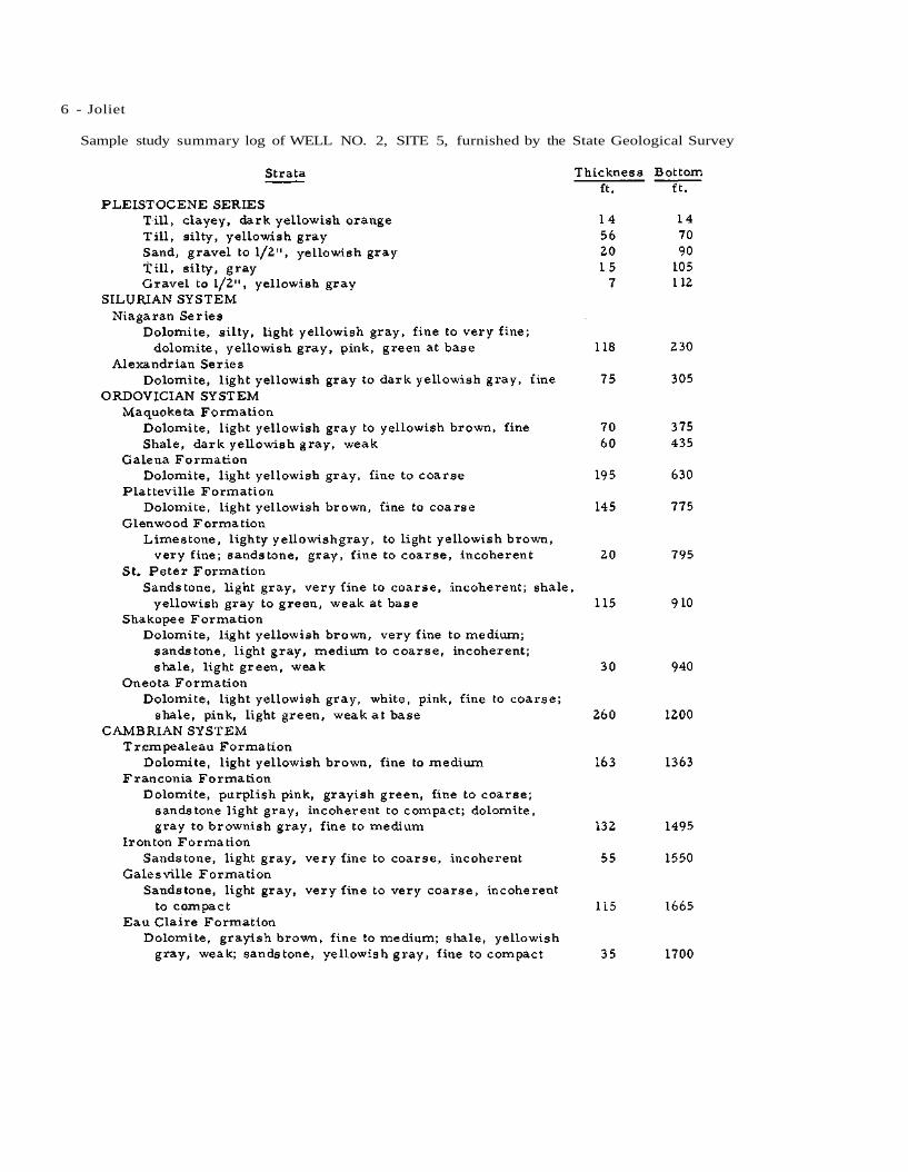
6 - Joliet
Sample study summary log of WELL NO. 2, SITE 5, furnished by the State Geological Survey

Joliet - 7
LABORATORY NO. 121163
LABORATORY NO. 122795

Illinois State Water Survey Bulletin 40 - Supplement II
JOY Mercer County July 16, 1958
Two wells are in service for the public water supply of the village of Joy (503).
WELL NO. 1, described in Bulletin 40, is available for service but is maintained for stand-by use only.
WELL NO. 2 was completed in Feb. 1948 to a depth of 420 ft. by Varner Well Co., Dubuque, Iowa, and located about 1/4 mile east of Well No. 1, or approximately 1760 ft. S. and 75 ft. E. of the N. W. corner of Section 20, T14N, R4W. The ground surface elevation at the well is 690. The well was cased with 18-in. pipe from the surface to 89 ft. and with 13 3/8-in. od. pipe from 2 ft. 11 in. above the surface to 151 ft. be-low. The annulus between the 2 casings was cemented in. The hole was finished 12 in. in diameter from the bottom of the inner casing to the bottom of the hole.
Static water levels during the drilling are shown in Table A.
TABLE A
Depth Depth of drilling to water
ft. ft.
Top to 214 0 234 145 292 140 302 144 322 135 344 130 366 137 420 132
A production test was conducted on Feb. 4-5, 1948 by representatives of the Driller, the State Water Survey, Village officials, and Beling Engineering Consultants. For test purposes the well was equipped with a turbine test pump as-sembly consisting of 2 50 ft. of 6-in. column pipe; 10 ft. of bowl section; 253 ft. of air line; 12 ft. of 6-in. suction pipe.
After 23 hr. pumping at a rate of 98 gpm.,
the drawdown was 113 ft. from a static water level of 137. 5 ft. below the top of the casing. Twenty-five min. after the pump was stopped, the water level had recovered to 144 ft.
A chemical analysis of a sample (Lab. No. 113403) collected Feb. 5, 1948, after 22 1/2 hr. pumping at 97 gpm., showed the water in Well No. 2 to have a hardness of 10 gr. per gal., total dissolved minerals of 664 ppm., and an iron content of 0. 8 ppm.
The permanent pump is a Fairbanks-Morse turbine rated at 85 gpm. and connected to a 7 l/2-hp. Fairbanks-Morse electric motor.
There are 185 services. Pumpage in July 1958 is estimated to average 33, 000 gpd.
Sample study summary and correlated driller's log of WELL NO. 2 furnished by the State Geo-logical Survey

2 - Joy
LABORATORY NO. 113403

Illinois State Water Survey Bulletin 40 - Supplement II
JUSTICE Cook County October 6, 1958
A public water supply was installed in 1954 for the village of Justice (2803).
Water is obtained from a well completed in Mar. 1954 to a depth of 145 ft. by J. P. Miller Artesian Well Co. , Brookfield. The well is owned and operated by Midwest-Justice Water Co. and is located in the southwest quadrant of the inter-section of 79th St. and 80th Ave., or approxi-mately 1430 ft. S. and 2150 ft. W. of the N. E. corner of Section 35, T38N, RUE. The ground elevation at the well is 618.
The well is cased with 86 ft. 9 in. of 10-in. gwi. pipe, below which the bore hole was finished at 10 in. in diameter. In a production test by the Driller in May 1954, the drawdown was 19 ft. be-low a nonpurr.ping water level of 15 ft. below the top of the casing, after 8 hr. pumping at a rate of 235 gpm.
The permanent pumping equipment includes 50 ft. of 5-in. column pipe; 8-in., 6-stage Peer -
less turbine pump, No. 38380, rated at 250 gpm. at 1760 rpm. ; 50 ft. of air line; 15-hp. U S elec-tric motor.
A mineral analysis of a sample (Lab. No. 146026) collected Mar. 18, 1958, after 5 min. pumping at a rate of 137 gpm., showed the water to have a hardness of 89. 5 gr. per gal . , total dissolved minerals of 2025 ppm., and an iron content of 2. 6 ppm.
Pumpage for 1957 averaged 21, 040 gpd.
Correlated dr i l ler ' s log furnished by the State Geological Survey
Strata Thickness Bottom ft. ft.
PLEISTOCENE SERIES Drift 80 80
SILURIAN SYSTEM Limestone 65 145
LABORATORY NO. 146026

Illinois State Water Survey Bulletin 40 - Supplement II
KAMPSVILLE Calhoun County September 17, 1959
A public water supply was installed for the village of Kampsville (453) in June 1959.
A Test Well was completed to a depth of 58 ft. in Apr. 1956 by Calhoun Drilling Co. , Batch-town, and located on the west side of Route 100 in the flat of Crawford Creek, 50 ft. west of the center line of the pavement and about 0. 9 mile south of Kampsville. An 8-in. casing was set to the bottom of the hole. The bottom 5 ft. of casing was slotted and exposed to the aquifer. The elevation of the top of the casing was 426.9 ft. According to the dr i l ler ' s log, the lower 8 ft. of the hole penetrated broken cherty rock and gravel. A production test was conducted on Apr. 4, 1956 by representatives of the Driller, the State Water Survey, and W. H. Klingner and Associates, Consulting Engineers. After 9 hr. pumping at a rate of 100 gpm., the drawdown was 23.52 ft. from a static water level of 18.92 ft. be-low the top of the casing. Twenty min. after pump-ing was stopped, the water level had recovered to 20. 05 ft.
WELL NO. 1 was completed to a depth of 60 ft. in July 1956 by Calhoun Drilling Co. and located at the site of the Test Well, or approxi-mately 2400 ft. N. and 1700 ft. E. of the S. W. corner of Section 11, T9S, R2W. An 8-in. casing was set with the bottom at 45 ft. followed by 15 ft. of Cook Everdur screen. The top 9 ft. of screen had No. 30 slot openings and the bottom 6 ft. had No. 80 slots.
A production test was conducted on July 11, 1956 by representatives of the Driller, the State Water Survey, and the Consulting Engineers.
After 9 hr. pumping at a rate of 100 gpm., the drawdown was 16. 25 ft. from a nonpumping water level of 18. 83 ft. below the pump base (elev. 427.16). Thirty-five min. after pumping was stopped, the water level had recovered to 19.89 ft.
During the test, water levels were noted in an observation well 65 ft. to the south. Elevation of the top of the casing in the observation well was 428. 20. At the end of the test, the water was lowered in the observation well to 1.5 ft. from the initial level of 20 ft. below the top of the casing.
The pumping equipment, ins tailed about Feb. 1959, consists of 45 ft. of 4-in. column pipe; 6-in., 4-stage MC. Fairbanks-Morse turbine pump (Serial No. A-284702), 3 ft. in length and rated at 100 gpm. ; 3-hp. Fairbanks-Morse electric motor.
A mineral analysis of a sample (Lab. No. 150648) collected Sept. 17, 1959 showed the water in Well No. 1 to have a hardness of 23. 4 gr. per gal . , total dissolved minerals of 430 ppm., and an iron content of 1. 9 ppm.
There are 150 meters installed andpumpage is estimated to average 12, 000 gpd.
Correlated dr i l ler ' s log of WELL NO. 1 furnish-ed by the State Geological Survey
LABORATORY NO. 150648

Illinois State Water Survey Bulletin 40 - Supplement II
KANGLEY LaSalle County October 26, 1960
The public water supply for the village of Kangley (267) was not completely installed in Oct. 1960.
WELL NO. 1 was drilled to a depth of 542 ft, in 1958 by Layne-Western Co., Aurora, and located adjacent to the village hall, or approxi-mately 660 ft. S. and 660 ft. E. of the N. W. corner of Section 22, T31N, R3E. The elevation of the ground surface at the well is 635.
The well was cased with 20-in. steel pipe from the surface to 85 ft., with 16-in. steel pipe from the surface to 245 ft., and with 10-in. pipe from the surface to 351 ft., below which the hole was finished 10 in. in diameter to the bottom. The 10-in. casing was cemented in the 15-in. hole
to 351 ft.
A production test was conducted by the Driller on Sept. 25, 1958. For the test a 6-in. Layne turbine test pump was installed on 4-in. column pipe. A 245-ft. air line was in place and power for pumping was from a Ford gas engine. After 8 hr. pumping at 100 gpm., the drawdown was 90 ft. from a nonpumping water level of 147 ft.
The permanent pump has not been installed.
A partial analysis of a sample (Lab. No. 148369) collected in Sept. 1958, after 8 hr. pump-ing at 100 gpm., showed the water to have a hard-ness of 19 gr. per gal., total dissolved minerals of 1401 ppm., and an iron content of 0. 3 ppm.
LABORATORY NO. 148369
Summary sample study log of WELL NO. 1 furnished by the State Geological Survey

Illinois State Water Survey Bulletin 40 - Supplement II
KANKAKEE RIVER STATE PARK Kankakee County October 10, 1960
Five wells are in use for the water supply serving the public and visitors to the Kankakee River State Park.
WELL NO. 1 was completed in Apr. 1953 to a depth of 96 ft. by Milaeger Well Drilling Co., Milwaukee, Wis., and located at the Custodian's office, 160 ft. south of the center line of Illinois Route 113N, about 900 ft. north of the north bank of the Kankakee River, or approximately 700 ft. S. and 1500 ft. W. of the N. E. corner of Sec-tion 5, T31N, RUE. The well was cased with a 10-in. drive pipe to 6 ft. depth and a 6-in. pipe from the surface to 25 ft. (cemented in), below which the hole was finished 6 in. in diameter to the bottom. The 6-in. casing was first set to a depth of 43 ft. but was pulled back to 25 ft. just above a crevice. The well was then acidized with 500 gal. of HC1. The ground surface eleva-tion at the well is 605.
Correlated driller's log of WELL NO. 1 furnished by the State Geological Survey
Strata Thickness Bottom ft. ft.
PLEISTOCENE SERIES Soil and yellow stone 6 6
SILURIAN SYSTEM Gray limestone 20 26 White limestone 45 7 1 Blue shale 25 96
A production test was conducted on May 5, 1953 by representatives of the Driller, the State Water Survey, and the State of Illinois Division of Architecture and Engineering. For test purposes the well was equipped with a rig-operated plunger pump with the bottom of the cylinder set at 44 ft. below the top of the 6-in. casing. After 12 hr. pumping on May 5, the test was discontinued be-cause of pump failure. Pumping was resumed on May 6 and after 23 hr. of continuous pumping at 7. 9 gpm., the drawdown was 20. 3 ft. from a nonpumping water level of 13 ft. below the top of the 6-in. casing. One hr. after pumping was stopped, the water level had recovered to 15. 5 ft.
The permanent pumping equipment includes a Jacuzzi turbine pump attached to 2-in. drop pipe with power furnished from a 2-hp. Century electric motor.
A mineral analysis of a sample (Lab. No. 153486) collected Oct. 10, 1960, after 15 min. pumping at 8 gpm., showed the water to have a hardness of 29 gr. per gal. , total dissolved min-
erals of 573 ppm., and an iron content of 0.1 ppm.
There is little information available on three other wells at the Park, which were drilled for private cottages before the land was purchased for use as a State Park.
CARDOSI COTTAGE WELL or Well No. 2 (this may now be the Camp Area Well) was re-portedly drilled to a depth of 95 ft. and located 1500 ft. N. and 1200 ft. E. of the S. W. corner of Section 4. The well was cased with 4-in. pipe to an unknown depth.
A partial chemical analysis of a sample (Lab. No. 129305) collected July 14, 1952 showed this water to have a hardness of 22. 3 gr. per gal . , total dissolved minerals of 429 ppm., and an iron content of 0. 3 ppm.
DWYER COTTAGE WELL (Well No. 3) was reportedly drilled about 1940 to a depth of 65 ft. and located approximately 900 ft. N. and 1500 ft. E. of the S. W. corner of Section 4. The well was cased with 30 ft. of 4-in. pipe. The static water level in 1940 was 27 ft. below the top of the casing.
PARK CUSTODIAN'S RESIDENCE WELL (called Well No. 4 in State Department of Public Health reports) was reportedly drilled in 1940 to a depth of 65 ft. and located approximately 150 ft. S. and 2700 ft. E. of the N. W. corner of Section 9, T31N, RUE. This is located on Lot 8 of Block 7, village of Altorf.
The well was cased with 22 ft. of 4-in. pipe. A jet pump is connected to a 30-gal. pressure tank. Water is furnished to theCustodian's residence and also a drinking fountain in the Custodian's yard.
This well is not located on State property but the water is available to Park patrons.
A well drilled at the WARD COTTAGE site to a depth of 80 ft. was located approximately 2025 ft. N. and 725 ft. E. of the S. W. corner of Section 4. The well has been abandoned and plug-ged.
WELL NO. 4, new camp site, was completed in 1958 to a depth of 102 ft. by Cecil Griffy, Kanka-kee, and located 2800 ft. N. and 2500 ft. E. of the S. W. corner of Section 36, T32N, R10E, Kankakee County,
When completed the static water level was 50 ft. below a surface elevation of 610.

2 - Kankak.ee River State Park
LABORATORY NO. 153486

I l l inois State Wate r Survey Bul le t in 40 - Supplement II
KEENSBURG Wabash County A p r i l 29, 1959
The ins ta l la t ion of a publ ic wa te r supply for the vi l lage of Keensburg (263) was in i t ia ted in 1959, but the d is t r ibu t ion s y s t e m was not comple ted . Water was obtained f rom a tap off a 4-in. pipe line to wa te r - f lood Well No. 1 owned by the T. W. George Oil Co. of Keensburg .
WELL NO. 1 was comple ted in May 1958 to a depth of 50 ft. by T. and M. P u m p and Equipmen t C o . , Evansv i l l e , Ind . , and loca ted about 3/4 mi l e sou theas t of Keensburg , or app rox i m a t e l y 675 ft. N. and 1650 ft. W. of the S. E. c o r n e r of Section 16, T2S, R13W. The ground su r face e levat ion at the well is 395.
C o r r e l a t e d d r i l l e r ' s log of WELL NO. 1 fu rn i shed by the State Geologica l Survey
Well No. 1 was cased with 12-in. s t ee l pipe f rom 1. 5 ft. above L. S. D. to 25 ft. followed
by 25 ft. of 12-in. Cook b r a s s s c r e e n having th ree sec t ions of slot openings; the upper 5 ft. had No. 100 s lo t s , the next 10 ft. had No. 35 s l o t s , and the bot tom 10 ft. with No. 25 s l o t s .
A product ion tes t was conducted on A p r . 29, 1959 by r e p r e s e n t a t i v e s of the D r i l l e r , the State Water Survey, and the B a r g e r Eng inee r ing Co. The p e r m a n e n t pump ins ta l la t ion cons i s t ed of 40 ft. of 4 - in . column pipe; 8 - in . , 17-s tage Byron J ackson tu rb ine , No. 357015, having a length of 8 ft. and r a t e d at 160 gpm. aga ins t 300 ft. T . D . H . ; 20-hp . U S e l e c t r i c m o t o r . After 1 h r . pumping at a r a t e of 100 g p m . , the d r a w down was 1 ft. f rom a nonpumping wa te r level of 5. 72 ft. below the top of the cas ing .
A m i n e r a l ana lys i s of a s amp le (Lab . No. 149509) co l lec ted Apr . 29, 1959, af ter 1 h r . pumping at a r a t e of 100 g p m . , showed the water in Well No. 1 to have a h a r d n e s s of 17. 5 g r . pe r g a l . , total d i sso lved m i n e r a l s of 376 p p m . , and an i ron content of 1. 8 ppm.
T h e r e a r e 48 s e r v i c e connect ions and 110 r e s i d e n t s have s igned for s e r v i c e . All s e r v i c e s a r e m e t e r e d .
Pumpage a t p r e s e n t i s e s t i m a t e d to a v e r a g e 7000 gpd.
LABORATORY NO. 149509

Illinois State Water Survey Bulletin 40 - Supplement II
KEITHSBURG Mercer County September 26, 1949
Two wells are in service for the public water supply of the city of Keithsburg (963).
The wells described in Bulletin 40 were abandoned about 1949 and after three test holes were drilled, two permanent wells were com-pleted and a new system was installed.
WELL NO. 1 was completed in 1949 to a depth of 81 ft. by Layne-Western Co., Ames, Iowa, and located in the northeastern part of town, at the site of Test Well No. 1-49, or ap-proximately 1000 ft. N. and 2530 ft. E. of the S. W. corner of Section 23, T13N, R5W. The ground surface elevation at the well is 545. A 10-in. hole was drilled to 64 ft. 5 in. then re-duced to 8 in. in diameter to the bottom of the well at 81 ft. The hole was cased with 10-in. id. welded steel pipe to a depth of 64 ft. 5 in. A 9 ft. 8 in. length of 8-in. pipe attached to the top of a 15 ft. length of 8-in. No. 8 Layne shutter screen, was baled in with the bottom of the screen set at 81 ft.
The pumping equipment, installed in Sept. 1949 prior to the production tests consists of 40 ft. of 4-in. steel column pipe; 8-in., 8-stage Layne turbine pump (No. 19966), 5 ft. long and rated at 100 gpm. against 215 ft. T.D.H.; 10 ft. of 4-in. suction pipe; 10-hp. U S electric motor. The pump is equipped with an auxiliary drive. The total length of column pipe, bowl section, and suction pipe is 55 ft. 5 in.
Production tests of Wells No. 1 and 2 were conducted on Sept. 22-23, 1949 by representa-tives of the Driller, the State Water Survey, City officials, and L. S. Pappmeier, Consulting En-gineer.
On Sept. 22, after 6 l/2 hr. pumping in Well No. 1 (with No. 2 idle) at a rate of 191 gpm., the drawdown was 26. 3 ft. from a static water level of 8.1 ft. below the pump base. During the pumping in Well No. 1, the water level in Well No. 2 dropped 2 ft.
WELL NO. 2 was completed in 1949 to a depth of 81. 5 ft. by Layne-Western Co. and lo-cated at the site of Test Well No. 2-49, about 9 ft. west of Well No. 1, or approximately 1000 ft. N. and 2520 ft. E. of the S. W. corner of Section 23.
Test Well No. 3-49 was located 20 ft. west of Well No. 2, or approximately 1000 ft. N. and 2500 ft. E. of the S. W. corner of Section 23.
Sample study summary log of TEST WELL NO. 3-49 furnished by the State Geological Survey
Well No. 2 was drilled 10 in. in diameter to a depth of 64 ft. 5 in. and below that the di-ameter of the hole was 8 in. to the bottom. The well was cased identical to that of Well No. 1.
The pumping equipment in Well No. 2 was identical to that in Well No. 1 except no auxiliary drive was installed. The Layne pump number is 19967.
On Sept. 23, 1949, the day following the production test in Well No. 1, a production test was conducted in Well No. 2. Nonpumping wa-ter levels were recorded in Well No. 1. The data recorded during the test of Well No. 2 were comparable to that recorded the day before when Well No. 1 was pumped.
Upon completion of the production test in Well No. 2, both wells were pumped simultane-ously. After 1 1/2 hr. pumping at rates of 150 gpm. in each well, the drawdowns were 20 ft. and 24. 2 ft. in Wells No. 1 and 2, respectively. Within 2 min. after the pump was stopped, the water levels had recovered completely.
A mineral analysis of a sample (Lab. No. 119408) collected Sept. 23, 1949, after 6 hr. pumping, showed the water in Well No. 2 to have a hardness of 10.9 gr. per gal., total dissolved minerals of 234 ppm., and an iron content of 0. 5 ppm.
Pumpage is estimated to average 40,000 gpd.

2 - Keithsburg
LABORATORY NO. 119408

Illinois State Water Survey Bulletin 40 - Supplement II
LA GRANGE Cook County October 31, 1958
There are five wells in service in the pub-lic water supply for the village of LaGrange (15,285).
WELL NO. 1, described inBulletin 40, was plugged at a depth of 459 ft. in 1957 by J. P. Miller Artesian Well Co., Brookfield. Before the plug was placed, water could be heard flow-ing into the well. The float and line measure-ment indicated water was entering the well at a depth of about 192 ft. The nonpumping water level, measured with counter attached to float and line was 220 ft. below the pump base (elev. 648. 5). Within a few min. after the plug was placed, the water level in the well was 162 ft., or 58 ft. higher than before the plugging operation.
Prior to the plugging of Well No. 1, the nonpumping water level in Well No. 3, approxi-mately 150 ft. southwest of Well No. 1, was 164 ft. below the pump base (645. 9) and after plug-ging Well No. 1, the water level in Well No. 3 was 146 ft. or 18 ft. higher.
The pumping equipment was reinstalled and consisted of an American Well Works turbine pump, No. 71337, rated at 1000 gpm.; 290 ft. of air line; 125-hp. General Electric motor.
WELL NO. 2 was abandoned several years ago. In Mar. 1956 J. P. Miller Artesian Well Co. completed sealing the well. The hole was opened to a depth of 960 ft. A 40 ft. length of cement plug was placed in the hole with the bot-tom at 960 ft. The hole was then filled succes-sively with pea gravel, cement grout, pea gravel, and topped with ready-mix concrete which was allowed to overflow the top of the casing which was 6 ft. below the surrounding ground surface.
WELL NO. 3 was treated with 5000 gal. of 15% HC1 on June 25, 1956. A bridge was found at a depth of 575 ft. Cement was poured in the well from 575 to 475 ft.
Before the cement was placed the hole had been backfilled with pea gravel and bank sand from 1196 to 575 ft., and before any of the back-filling the water level was 176 ft. After the hole was plugged at 475 ft. depth, the water level was 151 ft.
The following pumping equipment was in-stalled in Well No. 3: 260 ft. of 8-in. column pipe; 12-in., 6-stage Peerless turbine pump
(No. 98072); 30 ft. of 8-in. suction pipe; 262 ft. of air line; 100-hp. U S electric motor. For auxiliary power, a 4-cylinder, 100-hp. Climax gasoline engine was installed with a Peerless right angle gear drive, No. J17210.
Prior to the plugging of Well No. 1 in 1957, the nonpumping water level in Well No. 3 was 164 ft. below the pump base. Following the plugging operation the water level in Well No. 3 was 146 ft. or 18 ft. higher.
WELL NO. 4 is in service. No changes have been reported since Bulletin 40.
WELL NO. 5 was equipped in July 1950 with the following pump assembly: 295 ft. of 8-in. column pipe; 12-in., 5-stage Peerless tur-bine pump, No. 78484, rated at 700 gpm. at 325 ft. T.D.H.; 30 ft. of 8-in. suction pipe; 296 ft. of air line; 75-hp. General Electric motor.
A production test was conducted on Sept. 6, 1950 by representatives of J. P. Miller Ar-tesian Well Co. and the State Water Survey. After 5 hr. pumping at a rate of 475 gpm., the drawdown was 200 ft. from a nonpumping water level of 78 ft. below the pump base. Well No. 6, 1100 ft. east of Well No. 5, was being pumped at the same time and an interference of 2 ft. was noted while No. 5 was in operation.
A mineral analysis of a sample (Lab. No. 122864) collected Sept. 6, 1950, after 4 l/2 hr. pumping at 470 gpm., showed the water in Well No. 5 to have a hardness of 53. 5 gr. per gal., total dissolved minerals of 1138 ppm., and an iron content of 0. 9 ppm.
WELL NO. 6 was completed to a depth of 352 ft. in Oct. 1949 by J. P. Miller Artesian Well Co. and located near the intersection of the west side of Edgewood St. with the southproperty line of the C. B. & Q. Railroad, or approximately 2750 ft. N. and 3650 ft. E. of the S. W. corner of Section 5, T38N, R12E. The ground elevation at the well is 652. 4.
The well was cased with 24-in. pipe from the surface to 26 ft. 8 in., below which the hole was finished at 23 l/4 in. in diameter to the bot-tom at 352 ft.
A production test was conducted on Oct. 1, 1949 by representatives of the Drilling Contractor

2 - LaGrange
and the Village. After 16 hr, pumping at a rate of 1100 gpm., the drawdown was 205 ft. from a static water level of 75 ft. below the top of the casing.
Subsequently, the permanent pump assem-bly was installed, consisting of 200 ft. of 8-in. column pipe; 12-in., 5-stage Peerless turbine pump, No. 76716, having an over-all length of 5 ft. 5 in. and rated at 800 gpm. at 225 ft. T.D.H.;
30 ft. of 8-in. suction pipe; 196 ft. of air line; 75-hp. U S electric motor.
A partial chemical analysis of a sample (Lab. No. 148177) collected Oct. 31, 1958 showed the water in "Well No. 6 to have a hardness of 50. 6 gr. per gal., total dissolved minerals of 1199 ppm., and an iron content of 1. 3 ppm.
Pumpage for July 1957 averaged 1. 68 mgd.
LABORATORY NO. 148177

Illinois State Water Survey Bulletin 40 - Supplement II
LAKE BLUFF Lake County October 22, 1958
Since publication of Bulletin 40, the village of Lake Bluff (3494) has renumbered the munic-ipal wells; new pumping equipment has been in-stalled in Well No. 2 (formerly Well No. 4); and a new well, No. 3, has been drilled.
WELL NO. 1 (formerly No. 3) is main-tained for emergency use.
WELL NO. 2 (formerly No. 4) was drilled in 1921 by Wm. Cater, Chicago, to a depth of 1804 ft.
A production test was conducted on Mar. 3, 1950 by representatives of the Village and the State Water Survey. After 3 hr. pumping at a rate of 270 gpm., the drawdown was 28. 6 ft. from a nonpumping water level of 148.5 ft. Thirty m.in. after pumping was stopped, the water level had recovered to 150. 3 ft. In Dec. 1951 the Stan-nard Power Equipment Co., Chicago, installed new pumping equipment, consisting of 270 ft. of 6-in. column pipe; 10-in., 8-stage Fairbanks-Morse turbine pump, No. AM2416, rated at 500 gpm. at 180 ft. T.D.H.; 20 ft. of 6-in. suction pipe; 270 ft. of air line; 60-hp. U S electric mo-tor.
On Nov. 28, 1951 the static water level was 156 ft. below the surface compared to a static level of 57 ft. 9 in. in 1920 when the well was drilled.
WELL NO. 3 (fifth well of the village in order of drilling) was completed in Nov. 1956 to a depth of 1828 ft. by L. Cliff Neely, Batavia. Well No. 3 is located about 700 ft. west of Well No. 2, or approximately 1700 ft, S. and 300 ft. W. of the N. E. corner of Section 20, T44N, R12E. The ground elevation at the well is 685.
The hole and casing record is shown in Table A.
TABLE A
Hole Record
30-in. from 0 to 180 ft. 25-in. from 180 to 665 ft. 19-in. from 665 to 1260 ft. 15-in. from 1260 to 1693 ft. 12-in. from 1693 to 1828 ft.
Casing Record
30-in. od. from 0 to 171 ft. 20-in. od. from 0 to 665 ft. (cemented) 16-in. gwi. liner from 1109 to 1260 ft. 12-in. gwi. liner from 1378 to 1693 ft.
A production test was conductedon Nov. 20, 1956 by the Drilling Contractor. After 11 hr. pumping at a rate of 1420 gpm., the drawdown was 90 ft. from a nonpumping water level of 165 ft. below the surface.
Subsequently, the permanent pumping e-quipment was installed, consisting of 450 ft. of 8-in. column pipe; 10-stage Byron Jackson sub-mersible pump (No. 328456); 200-hp. electric motor.
A mineral analysis of a sample (Lab. No. 148037) collected Oct. 22, 1958, while pumping at a rate of 1526 gpm., showed the water in Well No. 3 to have a hardness of 20. 9 gr. per gal., total dissolved minerals of 510 ppm., and an iron con-tent of 2. 8 ppm.
Pumpage in July 1958 averaged 200, 000 gpd.
LABORATORY NO. 148037

Illinois State Water Survey Bulletin 40 - Supplement II
LAKE COUNTY PUBLIC WATER DISTRICT Lake County January 28, 1960
Two collectors are in service for the Lake County Public Water District (est. 15,000). The Water District furnishes water to Zion, Winthrop Harbor, Illinois Beach State Park, and a number of retail users in unincorporated communities.
WELL NO. 1 was originally constructed in Nov. 1952 by Ranney Method Water Supplies Inc., Columbus, Ohio, and reconditioned in 1957 when one 8-in. lateral and two 12-in. laterals were added to the original installation. The collector is located southeast of Zion, near the shore of Lake Michigan, or approximately 1320 ft. S. and 1056 ft. E. of the N. W. corner of Section 26, T46N, R12E. The ground surface elevation at the collector is 584. The reinforced concrete caisson (13 ft. id. by 16 ft. od.) was constructed 32 ft. 2 in. inside depth below the top (elev. 591. 3) and set on a 3/4-ft. thick concrete plug at the bottom. Two tiers of perforated steel pipe laterals were pushed out at depths of 27 and 30 ft. below the top of the caisson. The diameters and lengths of the laterals in each tier are shown in Table A. The perforations were approximately 1-in. by l/4-in. openings.
TABLE A
A Tier
Depth 30 ft.
Lateral Diameter Length
A-1 8 in. 200 ft. A-2 8 in. 72 ft. A-3 8 in. 80 ft. A-4 8 in. 80 ft.
. A-5 8 in. 184 ft.
B Tier
Depth 27 ft.
Lateral Diameter Length
B-1 12 in. 47 ft. B-2 12 in. 76 ft. B-3 12 in. 104 ft. B-4 8 in. 264 ft. B-5 8 in. 96 ft.
Subsequently, the A laterals were closed
and the B laterals were open except B-5. The collector was placed in service Aug. 1, 1957 with the following pumping equipment: 28 ft. of 8-in. column pipe; two 12-in., 5-stage Pomona turbine pumps, No. AV2516, rated at 750 gpm. against 230 ft. T.D.H.; 60-hp. Fairbanks-Morse electric motor. A Fairbanks-Morse right angle gear drive with a 6 cylinder, 70-hp. Continental gas engine was installed for auxiliary power.
On Nov. 20, 1958, after 1 hr. pumping at a rate of 700 gpm., the drawdown was 7 ft. from a nonpumping water level of 15 ft. below the pump base.
A partial chemical analysis of a sample Lab. No. 143242) collected 44 l/2 hr. after pump-ing began at a rate of 1200 gpm., showed the wa-ter in Well No. 1 to have a hardness of 11.2 gr. per gal., total dissolved minerals of 222 ppm., and an iron content of 0. 7 ppm.
Water from Well No. 1 is pumped directly into the distribution system.
WELL NO. 2 was constructed in Mar. -July 1959 by Ranney, identical to Well No. 1 and located about 300 ft. south and 25 ft. east of Well No. 1, or approximately 300 ft. S. and 1080 ft. E. of the N. W. corner of Section 26.
Following the completion of the well, the Contractor reported pumping for 36 hr. at a rate of 700 gpm.
A partial chemical analysis of a sample (Lab. No. 150131) collected after 36 hr. pumping at a rate of 700 gpm., showed the water in Well No. 2 to have a hardness of 9 gr. per gal., total dissolved minerals of 182 ppm., and an iron con-tent of 0. 6 ppm.
Well No. 2 was placed in service Oct. 1, 1959 and is equipped with two submersible pumps rated at 1000 gpm. and 325 gpm. against 20 ft. T.D.H. Water from Well No. 2 is pumped into Well No. 1.
A 100, 000 gal. elevated storage tank is lo-cated in Zion and a 60, 000 gal. elevated tankis in Winthrop Harbor.
Pumpage to Zion in 1959 averaged 0. 57 mgd.

2 - Lake County Public Water District
Pumpage to Winthrop Harbor July 1, 1959 to Jan. 1, 1960 averaged 0.16 mgd.
Total pumpage to Illinois Beach State Park in 1959 amounted to 67,000 gal. and to retail
users in unincorporated areas, 52, 000 gal.
Total pumpage in 1959 was 236.4 mg., an average of 0. 65 mgd. for the period the system was in service.
LABORATORY NO. 150131

Illinois State Water Survey Bulletin 40 - Supplement II
LAKELAND PARK SUBDIVISION McHenry County February 10, 1959
One well is in service for the public water supply of Lakeland Park Subdivision (est. 1000), located west of McHenry.
WELL NO. 1 was completed in 1954 to a depth of 86 ft. by Art Wertz, Antioch, and located approximately 1000 ft. S. and 1600 ft. E. of the N. W. corner of Section 27, T45N, R8E. The ground surface elevation at the well is 758. The well was cased with 86 ft. of 8-in. pipe.
WELL NO. 2 was completed in 1956 to a depth of 85 ft. by Henry Boysen, Libertyville, and located about 1/8 mile east of Well No. 1, or approximately 1150 ft. S. and 2300 ft. E. of the N. W. corner of Section 27. The elevation of the ground surface at the well is 757. The well was cased with 12-in. pipe followed by 15 ft. of 12-in. Cook screen having No. 14 slot openings.
When the well was being developed in 1956, a quantity of acid was introduced, following which the yield rate was 146 gpm. On May 23, 1958 the
well was flowing.
The permanent pumping equipment consists of 20 ft. of 4-in. suction pipe; Weinman centrif-ugal pump; 20-hp. General Electric motor.
A mineral analysis of a sample (Lab. No. 146785) collected May 23, 1958 showed the water in Well No. 2 to have a hardness of 23. 8 gr. per gal., total dissolved minerals of 469 ppm., and an iron content of 1. 3 ppm.
WELL NO. 3 was completed in 1954 to a depth of 190 ft. by Henry Boysen and located about 1/8 mile north of Well No. 2, or approximately 600 ft. S. and 2250 ft. E. of the N. W. corner of Section 27. The ground surface elevation at the well is 760.
The well was capped.
There are 310 services and pumpage is estimated to average 60, 000 gpd.
LABORATORY NO. 146785

Illinois State Water Survey Bulletin 40 - Supplement II
LAKEWOOD SHORES SUBDIVISION Will County May 25, 1960
A public water supply was installed in 1953 for the Lakewood Shores Subdivision, located along the Kankakee River about 1 l/2 miles south of Wilmington. Water is obtained from three wells. The system is owned and operated by the Lakewood Shores Real Estate Development Co.
WELL NO. 1 was completed to a depth of about 720 ft. and located at 1800 Roberts St. The well is cased with 5-in. steel pipe to an un-reported depth. A Reda submersible pump is installed and connected to a 3-hp. electric mo-tor.
WELL NO. 2 was constructed about the same time as Well No. 1 but no definite infor-mation is available other than that it was similar to Well No. 1 and located at 211 Lakewood Drive.
WELL NO. 3 was completed in Oct. 1953 to a depth of 700 ft. by Dreher and Schorie,
Joliet, and located at 332 Sumac St., or approx-imately 1650 ft. N. and 3500 ft. W. of the S. E. corner of Section 1, T32N, R9E. The ground surface elevation at the well is 562. The well was first drilled to 300 ft. in the fall of 1952 but when it produced about 5 gpm., it was drilled deeper penetrating the St. Peter sandstone. The well is cased with 6-in. steel pipe to an unre-ported depth. "
The permanent pump is a Red Jacket sub-mersible driven by a 3-hp. electric motor.
A mineral analysis of a sample (Lab. No. 152393) collected May 25, 1960 showed the water to have a hardness of 19.9 gr. per gal., total dissolved minerals of 385 ppm., and an iron content of 0.2 ppm.
There are 130 services. Pumpage is esti-mated to average 26,000 gpd.
LABORATORY NO. 152393

Illinois State Water Survey Bulletin 40 - Supplement II
LAKE ZURICH Lake County February 10, 1959
Two wells are in service for the public wa-ter supply of the village of Lake Zurich (3458).
WELL NO. 1 has been abandoned and filled in.
WELL NO. 2, described in Bulletin 40 as the "second well" and drilled in 1921 to a depth of 213 ft., was deepened in 1957 to a depth of 421 ft. by Henry Boysen, Libertyville. The well is located 690 ft. S. and 1950 ft. E. of the N. W. corner of Section 20, T43N, R10E. The ground surface elevation at the well is 855. The well was cased with 10-in. pipe to rock at 272 ft. and finished 10 in. in diameter to the bottom.
A production test was conducted by repre-sentatives of the Driller and the State Water Sur-vey on July 26, 1957. After 4 hr. pumping at a rate of 505 gpm., the drawdown was 11 ft. from a static water level of 108 ft. below the top of the casing (2 ft. above floor).
A mineral analysis of a sample (Lab. No. 125969) collected July 26, 1951, after 4 hr. pump-ing, showed the water in Well No. 2 to have a hardness of 51 gr. per gal., total dissolved min-
erals of 1514 ppm., and an iron content of 1.1 ppm.
The pumping equipment consists of 180 ft. of 8-in. column pipe; 10-in., 8-stage Cook tur-bine pump, No. 13863, rated at 550 gpm. against 255 ft. T.D.H.; 10 ft. of 6-in. suction pipe; 180 ft. of air line; 40-hp. U S electric motor.
On June 6, 1958 the nonpumping water level was 134 ft. (air line reading).
Well No. 2 is in service,
WELL NO. 3, described in Bulletin 40, is equipped with a 5-in. Cook turbine pump, No. 12413, rated at 325 gpm., attached to 4-in. col-umn pipe. Power for pumping is from a 20-hp. U S electric motor.
Well No. 3 is in service.
In June 1958 there were 885 dwelling units, with 730 meters.
Pumpage is estimated to average 156, 000 gpd.
LABORATORY NO. 125969

Illinois State Water Survey Bulletin 40 - Supplement II
LANARK Carroll County October 10, 1960
Two wells are in service for the public supply of the city of Lanark (1473).
WELL NO. 1, described in Bulletin 40, was abandoned in 1957.
WELL NO. 2, described in Bulletin 40, is in service.
WELL NO. 3 was completed in 1957 to a depth of 1300 ft. by Allabaugh Well Co., Rock-ford, and located about 1/8 mile southeast of Well No. 2, or approximately 2300 ft. S. and 2300 ft. E. of the N. W. corner of Section 5, T24N, R6E. The ground surface elevation at the well is 860. The well was cased with 18-in. pipe from the surface to 90 ft. and with 14-in. pipe from the surface to about 340 ft. (cemented in). The hole was finished 14 in. in diameter to
the bottom.
The well is equipped with a Fairbanks-Morse Pomona turbine pump, rated at 400 gpm., connected to a 50-hp. electric motor.
On Oct. 6, 1960, after 15 min. pumping at 500 gpm., the pumping water level was 273. 5 ft. (air line reading).
A mineral analysis of a sample (Lab. No. 153354) collected Oct. 6, 1960, after 15 min. pumping, showed the water in Well No. 3 to have a hardness of 17. 7 gr. per gal., total dissolved minerals of 323 ppm., and an iron content of 0. 5 ppm.
For the 12-month period prior to Apr. 1, 1959 pumpage for the city of Lanark averaged 150,000 gpd.
LABORATORY NO. 153354

2 - Lanark
Sample study summary log of WELL NO. 3 furnished by the State Geological Survey

Illinois State Water Survey Bulletin 40 - Supplement II
LEMONT Cook County May 15, 1958
Two wells are in service for the village of Lemont (3397).
WELL NO. 1, which is described in Bulle-tin 40, was originally Well No. 2 or the Stephens St. Well, also locally known as the "Sandstone Well." The well is now maintained for emergen-cy service. Due to its higher power cost, Well No. 1 is operated only when the present Well No. 2 is out of service.
WELL NO. 2, locally known as the "Lime-stone Well," was completed in Dec. 1954 to a depth of 240 ft. by J. P. Miller Artesian Well Co., Brookfield, and is located about 1 mile south of Well No. 1, or approximately 800 ft. N. and 2300 ft. W. of the S. E. corner of Section 29, T36N, R11E. The ground surface elevation at the well is 742.
The well was cased with 128 ft. of drive pipe, below which the hole was finished 12 in. in diameter to the bottom at 240 ft. An 8-in. test hole was authorized by the village but the Driller put down a 12-in. hole. When the test hole was completed, a production test was conducted by the Driller. After 5 l/2 hr. pumping at a rate of 530 gpm., the drawdown was 9 ft. from a
static water level of 111 ft. below the top of the casing.
The permanent pump installation consists of 170 ft. of column pipe; Peerless turbine pump; 170 ft. of air line; 30-hp. electric motor.
In July 1956 the standing water level was reportedly 4 ft. above the pump bowls and the pumping level was below the top of the bowls. The permanent pump was originally set with the top of the bowls at 132 ft. In Sept. 1956 the pump was lowered to 170 ft. and the air line was ex-tended to 170 ft.
A mineral analysis of a sample (Lab. No. 146786) collected May 15, 1958 showed the water in Well No. 2 to have a hardness of 38.4 gr. per gal., total dissolved minerals of 788 ppm., and an iron content of 0. 5 ppm.
In Mar. 1957, because of cheaper power costs, all water for the village supply was being pumped from Well No. 2.
Pumpage for the village in 1956 averaged 200,000 gpd.
LABORATORY NO. 146786

Illinois State Water Survey Bulletin 40 - Supplement II
LEWISTOWN Fulton County June 28, 1960
Four wells are in service for the city of Lewistown (2603).
WELL NO. 1, described in Bulletin 40, was in service until 1958 when it was used as an ob-servation well. On Nov. 13, 1958 the static water level was reportedly 16 ft. below the well top.
WELLS NO. 2, 3 and 4, described in Bul-letin 40, were abandoned in 1952, 1953 and 1955, respectively.
WELL NO. 5 was completed to a depth of 46 ft. in 1950 by Thorpe Concrete Well Co., Alton, and located about 33 ft. north of Well No. 3, or approximately 400 ft. N. and 2100 ft. W. of the S. E. corner of Section 32, T5N, R3E. The elevation of the ground surface at the well is 455. The well was cased with 30-in. id. by 40-in. od. plain concrete pipe from 2 1/4 ft. above to 26 ft. below ground level, followed by a 30-in. id. by 40-in. od. porous concrete screen from 26 to 46 ft.
A production test was conducted on Apr. 26-27, 1955 by representatives of the Driller, the State Water Survey, and Casler and Stapleton, Consulting Engineers. After 6 hr. pumping at an average rate of 178 gpm., the drawdown was 11. 5 ft. from a static water level of 10. 9 ft. below the top of the casing.
A partial analysis of a sample (Lab. No. 137533) collected Apr. 27, 1955, after 6 hr. pump-ing at 178 gpm., showed the water in Well No. 5 to have a hardness of 23.2 gr. per gal., total dissolved minerals of 415 ppm., and an iron con-tent of 0. 5 ppm.
The pumping installation consists ofa Dem-ing turbine pump, rated at 725 gpm., connected to a 2-hp. U S electric motor.
WELL NO. 6 was completed in 1950 to a depth of 45 ft. by Thorpe Concrete Well Co. and located 70 ft. east of Well No. 5. Construction details and pumping equipment are identical with those for Well No. 5.
WELL NO. 7 was completed in Mar. 1956 to a depth of 35 ft. by Varner Well and Pump Co., Dubuque, Iowa, and located 10 ft. north and 175 ft. west of Well No. 5. The hole was drilled 42 in. in diameter from the surface to 35 ft. and is cased with 12-in. id., ci. pipe from 7 ft. above to 25 ft. below ground level followed by 10 ft. of
12-in. stainless steel screen having .050 slot openings. The annulus between the casing and screen and the wall of the 42-in. hole was filled with 1/4 to 1/8-in. gravel from 35 ft. up to 5 ft. below the surface.
A production test was conducted on Mar. 23, 1956 by representatives of the Driller, Vil-lage officials, the State Water Survey, and Cas-ler and Stapleton, Consulting Engineers. After 8 hr. pumping at 300 gpm., the drawdown was 6. 5 ft. from a static water level of 11 ft. below ground level. Eighteen min. after the pump was stopped, the water level had recovered to 11.5 ft.
The pumping equipment consists of a Dem-ing turbine pump, rated at 125 gpm., connected to a 2-hp. U S electric motor.
WELL NO. 8 was completed in 1956 to a depth of 35 ft. by Varner Well and Pump Co. and located 111 ft. west of Well No. 7, or approxi-mately 410 ft. N. and 2386 ft. W. of the S. E. corner of Section 32.
Construction details and pumping equipment are identical with those of Well No. 7.
Correlated driller's log of WELL NO. 8 furnish-ed by the State Geological Survey
Strata Thickness Bottom ft. ft.
PLEISTOCENE SERIES Black top soil 5 5 Red clay 10 15 Medium white clean sand 5 20 Fine gravel, coarse
sand 5 25 Coarse gravel 5 30 Coarse gravel, coarse
white sand 5 35 Blue clay 35
A mineral analysis of a composite sample (Lab. No. 152608) collected June 23, 1960 showed the water from Wells No. 5, 6, 7 and 8 to have a hardness of 21. 2 gr. per gal., total dissolved minerals of 424 ppm., and an iron content of 1.2 ppm.
Pumpage in Mar. 1957 averaged 145,000 gpd. This is less than 1950 pumpage, probably because of change over of railroad locomotives from steam to diesel power.

2 - Lewistown
LABORATORY NO. 152608

Illinois State Water Survey Bulletin 40 - Supplement II
LIBERTY PARK SUBDIVISION DuPage County June 25, 1958
A public water supply was installed in 1927 for the Liberty Park Subdivision (est. 720) lo-cated just east of Downers Grove and north of Westmont. The area is generally between Wash-ington St. on the east and Jackson St. on the west and between Ogden Ave. on the south and 38th St. on the north. The system is owned and op-erated by the Liberty Park Home Owners Asso-ciation.
WELL NO. 1 was constructed 120 ft. deep about 1926 or 1927. The name of the Driller is not known. The well was located in a 5-ft. pit at the corner of Washington St. and 41st St., or approximately 1900 ft. S. and 1500 ft. W. of the N. E. corner of Section 4, T38N, R11E. The elevation of the ground surface at the well is 745.
The size and amount of casing in the well are not known. The pumping equipment includes a Fairbanks-Morse Pomona turbine pump, No. SC1468, rated at 200 gpm. atl60ft. T.D.H. Power is from a 10-hp. Fairbanks-Morse electric mo-tor.
Well No. 1 furnished the subdivision sup-ply until Well No. 2 was constructed. At pres-ent Well No. 1 is maintained for stand-by use.
WELL NO. 2 was completed in July 1956 to a depth of 278 ft. 9 in. by Layne-Western Co., Aurora, and located about 25 ft. east of Well No. 1, or approximately 1875 ft. S. and 1475 ft. W. of the N. E. corner of Section 4. The well was cased with 8-in. steel pipe to 142 ft. 8 in. and the hole was finished at 8 in. in diameter to the bottom at 278 ft. 9 in. The casing sets in a pit 11 ft. 6 in. deep and the top of the casing is 6 in. above grade (ground level at entrance to pump house).
The Drilling Contractor reported that on July 31, 1956 water was pumped for 9 hr. at a rate of 156 to 96 gpm. with a final drawdown of 25 ft. from a static water level of 105 ft. below the pump base (3 ft. above ground level).
The pumping equipment consists of 760 ft.
of 4-in. column pipe; 8-in., 10-stage Layne tur-bine pump (No. 34815), 6 ft. 2 in. long and rated at 100 gpm. at 275 ft. T.D.H.; 15-hp. U S electric motor.
A partial chemical analysis of a sample (Lab. No. 141147) collected in Aug. 1956 showed the water in Well No. 2 to have a hardness of 30.7 gr. per gal., total dissolved minerals of 539 ppm., and an iron content of 0. 7 ppm.
Pumpage for May 1958 averaged 30,000 gpd.
Sample study summary log of WELL NO. 2 fur-nished by the State Geological Survey

2 - Liberty Park Subdivision
LABORATORY NO. 141147

Illinois State Water Survey Bulletin 40 - Supplement II
LIBERTYVILLE Lake County December 18, 1958
Six wells are in service for the public wa-ter supply of the village of Libertyville (8560).
WELL NO. 1, described in Bulletin 40 as the Second St. Well, was the fifth well drilled for Libertyville. The four wells previously drilled were abandoned, as stated in Bulletin 40. The ground elevation at the well is 680. Well No. 1 is now equipped with 200 ft. of 6-in. column pipe; 8-in., 8-stage Pomona turbine pump, No. SD1605, ratedat 300 gpm. against 230 ft. T.D.H.; 200 ft. of air line; a 5-in. strainer on the suction; 25-hp. Westinghouse electric motor.
On Dec. 18, 1958, during pumping at a rate of 300 gpm., the drawdown was 57 ft. from a nonpumping water level of 96 ft. (air line read-ing).
WELL NO. 2, described in Bulletin 40 as the Garfield Ave. Well, the sixth well drilled for the village, is equipped with 73 ft. of 7-in. col-umn pipe; 8-in., 9-stage Pomona turbine pump, No. L-2690, rated at 400 gpm. against 190 ft. T.D.H.; strainer at bottom of pump; 73 ft. of air line; 30-hp. General Electric motor.
On Dec. 18, 1958, during pumping at 400 gpm., the drawdown was 25 ft. from a nonpump-ing water level of 43 ft.
Well No. 2 is maintained for stand-by use and has not been in regular service since Oct. 1955.
WELL NO. 3, described in Bulletin 40 as Appley No. 1, the seventh well drilled by the vil-lage, was completed and tested in Jan. 1948. The well was subsequently equipped with 100 ft. of 6-in. column pipe; 8-in., 12-stage Pomona turbine pump, No. SF767, rated at 325 gpm. against 200 ft. T.D.H.; strainer on bottom of bowls; 100 ft. of air line; 20-hp. General Electric motor.
On Dec. 18, 1958, after 8 hr. pumping at a rate of 325 gpm., the drawdown was 14 ft. from a nonpumping water level of 52 ft. (air line read-ing). When Well No. 4, old Test Well 46-1 at 10 ft. away was also pumping, the drawdown in No. 3 was 25 ft.
WELL NO. 4, referred to in Bulletin 40 as Test Well No. 46-1, was drilled in 1946 to a depth of 286 ft. and located 10 ft. south of the perma-
nent well, Appley St. No. 1 (now called Well No. 3). Following the favorable production test in the test well (Test Well No. 46-1), it was com-pleted in 1947 as a permanent well (Appley St. No. 2) and now known as Well No. 4. The ground surface elevation at the well is 675, and the well was cased with 6-in. pipe to an unreported depth (probably about 172 ft., the same as Well No. 3).
The pumping equipment includes 130 ft. of 4-in. column pipe; 6-in., 23-stage Pomona tur-bine pump, No. AL4703, rated at 150 gpm. a-gainst 241 ft. T.D.H.; strainer at bottom of pump; 130 ft. of air line; 15-hp. General Elec-tric motor.
On Dec. 18, 1958, during pumping at a rate of 150 gpm., the drawdown was 14 ft. from a nonpumping water level of 52 ft.
A partial chemical analysis of a sample (Lab. No. 122966) collected Sept. 13, 1950, after l/2 hr. pumping at rates of 200 to 250 gpm., show-ed the water in this well to have a hardness of 20.4 gr. per gal., total dissolved minerals of 630 gpm., and an iron content of 0.6 ppm.
WELL NO. 5 (Newberry Ave. ) was com-pleted in 1951 to a depth of 227 ft. by Henry Boysen, Libertyville, and located on Newberry Ave., about l/2 mile south of Wells No. 3 and 4, or approximately 2210 ft. N. and 2230 ft. W. of the S. E. corner of Section 16, T44N, R11E. The ground surface elevation at the well is 693. The well was cased with 12-in. pipe to 174 ft. (lime-stone), below which the hole was finished 12 in. in diameter.
A production test was conducted on Feb. 27, 1951 by representatives of the Driller and the State Water Survey. After 12 hr. pumping at rates of 305 to 590 gpm., the drawdown was 43 ft. from a static water level of 39 ft. below the pump base (1 ft. above ground level).
The well is equipped with 140 ft. of 8-in. column pipe; 10-in., 6-stage Pomona turbine pump, No. 5787, rated at 500 gpm. against 225 ft. T.D.H.; strainer at bottom of pump; 140 ft. of air line; 40-hp. Fairbanks-Morse electric mo-tor.
On Dec. 18, 1958, when pumping at a rate

2 - Libertyville
of 500 gpm., the drawdown was 26 ft. from a nonpumping water level of 79 ft. (air line read-ing).
A mineral analysis of a sample (Lab. No. 124509) collected Feb. 27, 1951, after 12 hr. pumping at rates of 305 to 590 gpm., showed the water to have a hardness of 17.5 gr. per gal., total dissolved minerals of 736 ppm., and an iron content of 0.1 ppm.
WELL NO. 6 (North Ave.) was completed in Apr. 1955 to a depth of 297 ft. by Henry Boysen and located at the end of North Ave., south of the sewage treatment plant, or approximately 1110 ft. N. aud 50 ft. W. of the S. E. corner of Section 16. This is about 1/2 mile southeast of Well No. 5. The ground surface elevation at the well is 648. The well was cased with 6-in. pipe to 198 ft., below which the hole was finished at 6 in. in diameter. The top 70 ft. of the casing was cemented in. The top of the casing was left 18 in. above the pump house floor. Limestone and shale were encountered at 188 ft.
When the well was completed, a production test was conducted and reported by the Driller. While pumping at a rate of 376 gpm., the draw-down was 180 ft. from a static water level of 20 ft. below the surface. Development of the well was continued on Apr, 13, 1955 by introducing 4000 gal. of HC1. On Apr. 15, during pumping at a rate of 728 gpm., the drawdown was 150 ft. from a nonpumping water level of 20 ft. below the surface.
The pumping equipment consists of 220 ft. of 4-in. column pipe; 6-in., 4-stage Pomona tur-bine pump, No. AT7273, rated at 200 gpm, a-gainst 380 ft. T.D.H.; strainer on bottom of
pump; 220 ft. of air line; 30-hp. U S electric mo-tor.
WELL NO. 7, the tenth well in the order of drilling for the village supply, was completed in May 1955 to a depth of 300 ft. by Henry Boysen and located 8 ft. west of Well No. 6, or approxi-mately 1110 ft. N. and 58 ft. W. of the S. E. cor-ner of Section 16, This well was originally drilled as a test well and used for observation of water levels during the production tests of Well No. 6. The finished well was cased with 24-in. outer pipe from the surface to 56 ft. and with a 16-in. inner pipe (cemented in) from the surface to 198 ft. Below the casing the hole was finished 16 in. in diameter.
On May 4, 1955, when pumping at a rate of 630 gpm., the drawdown was 155 ft. from a non-pumping water level of 33 ft. below the top of the casing. Prior to this test 3300 gal. of HC1 had been introduced into the well.
The pumping equipment consists of 260 ft. of 8-in. column pipe; 12-in., 6-stage Pomona turbine pump, No. 7277, rated at 700 gpm. a-gainst 290 ft, T.D.H.; strainer on bottom of pump; 260 ft. of air line; 75-hp. U S electric motor. A right angle gear drive with a 130-hp. Buda gas engine is installed for auxiliary power for pumping.
A partial chemical analysis of a sample (Lab. No. 137590) collected May 4, 1955, after 6 hr. pumping at a rate of 630 gpm., showed the water in Well No. 7 to have a hardness of 19.4 gr. per gal., total dissolved minerals of 552 ppm., and an iron content of 0. 6 ppm.
Pumpage for the village during 1957 av-eraged 700,000 gpd.
LABORATORY NO. 124509

Illinois State Water Survey Bulletin 40 - Supplement II
LINCOLNSHIRE Lake County August 15, 1958
A public water supply was installed in 1956 for Lincolnshire (555), a village near Half Day. The system was owned by the J. R. Ladd Enterprises.
WELL NO. 1 was completed in 1956 to a depth of 1305 ft. by Henry Boysen, Libertyville, and located about 1/2 mile southeast of Half Day, or approximately 800 ft. S. and 2100 ft. E. of the N. W. corner of Section 23, T43N, R11E. The ground surface elevation at the well is 650. The well was cased with 12-in. pipe from the surface to 138 ft. and with 10-in. pipe from the surface to 555 ft. An 8-in. liner was set from 941 to 1026 ft., below which the hole was finished 10 in. in diameter.
When the well was completed the Driller reported pumping for 8 hr. at a rate of 195 gpm. with a drawdown of 100 ft. from a static water level of 230 ft. below the surface.
The permanent pumping equipment consists of 310 ft. of 4-in. column pipe; 8-in., 10-stage Byron Jackson submersible pump, rated at 200 gpm. against 450 ft. T.D.H.; 320 ft. of air line; 35-hp. electric motor.
The nonpumping water level on Aug. 15, 1958 was 238 ft. (air line reading).
A partial chemical analysis of a sample
(Lab. No. 145347) collected Dec. 27, 1957, after 8 hr. pumping at 195 gpm., showed the water in the well to have a hardness of 19.2 gr. per gal., total dissolved minerals of 539 ppm., and an iron content of 1. 4 ppm.
In Aug. 1958 there were 103 services. Pumpage was estimated to average 24, 000 gpd.
Correlated driller's log of WELL NO. 1 furnish-ed by the State Geological Survey
LABORATORY NO. 145347

Illinois State Water Survey Bulletin 40 - Supplement II
LOCKPORT HEIGHTS SUBDIVISION Will County April 3, 1958
A public water supply was installed in 1953 for the Lockport Heights Subdivision. Two wells are in service.
WELL NO. 1 was completed in 1953 to a depth of 200 ft. and located approximately 3050 ft. N. and 175 ft. E. of the S. W. corner of Sec-tion 7, T36N, R11E. The ground surface eleva-tion at the well is 720. The well was cased with 6-in. pipe to an unreported depth.
Well No. 1 is equipped with a Reda sub-mersible pump attached to a 4-in. discharge pipe and powered by a 3-hp. electric motor.
WELL NO. 2 was completed in 1955 to a depth of 200 ft. by Dreher and Schorie, Joliet,
and located about 1/4 mile northeast of Well No. 1, or approximately 3600 ft. N. and 1425 ft. E. of the S. W. corner of Section 7. The ground surface elevation at the well is 745.
The well is cased with 6-in. pipe to an un-reported depth, and is equipped with a Reda sub-mersible pump attached to a 4-in. discharge pipe. Power is from a 3-hp. electric motor.
A mineral analysis of a sample (Lab. No. 146279) collected Apr. 3, 1958 showed the water in Well No. 2 to have a hardness of 52 gr. per gal., total dissolved minerals of 1119 ppm., and an iron content of 1. 3 ppm.
Pumpage has not been reported.
LABORATORY NO. 146279

Illinois State Water Survey Bulletin 40 - Supplement II
LODA Iroquois County June 22, 1960
Two wells are in service for the village of Loda (585).
WELL NO. 1, described in Bulletin 40, was cleaned with Weltone in Nov. 1959 and the capacity reportedly increased from 80 to 110 gpm.
WELL NO. 2 was completed in June 1951 to a depth of 158 ft. by J. Bolliger and Sons, Fairbury, and located about 15 ft. northeast of Well No. 1, or approximately 190 ft. S. and 2505 ft. W. of the N. E. corner of Section 28, T24N, R10E. The elevation of the ground surface at the well is 780. The well was cased with 149 ft. of 8-in. pipe from 1. 5 ft. above ground level. A Houston stainless steel screen, 12 ft. 2 in. long, was installed by the casing "pull-back method. " The lower half of the screen had No. 21 slot sizes and the upper half had No. 30 slot sizes.
A production test was conducted on June 13, 1951 by representatives of the Driller, the State Water Survey, Village officials, and Tracy Pitzen, Consulting Engineer.
For the test a deep-well engine driven tur-
bine pump was set with the bottom of the suction at a depth of 145 ft. Before the test, and with the pump in Well No. 1 not operating, the static water level in Well No. 2 was 99. 5 ft. below the top of the casing. After 2 l/2 hr. pumping at 157 gpm. in Well No. 2, with No. 1 still idle, the drawdown in Well No. 2 was 24. 8 ft. Two hr. after starting the Well No. 1 pump, and with simultaneous pumping in both wells (No. 2 at 154 gpm. ) the drawdown in Well No. 2 was 28.1 ft.
The permanent pump is a Deming turbine, rated at 150 gpm. and connected to a 15-hp. U S electric motor.
A mineral analysis of a sample (Lab. No. 152588) collected June 22, 1960 showed the water in Well No. 2 to have a hardness of 34. 6 gr. per gal., total dissolved minerals of 866 ppm., and an iron content of 1. 4 ppm.
There are 197 services, all metered, and pumpage is reported to average 37, 000 gpd.
A Poultry Packing Co. uses an average of 6000 gpd. from another well.
LABORATORY NO. 152588

Illinois State Water Survey Bulletin 40 - Supplement II
LOMBARD DuPage County May 14, 1959
Two wells, No. 4 and 5, are in service for the village of Lombard (22, 561). Two wells, No. 1 and 3, are available for emergency service and Well No. 2 is temporarily, at least, out of use.
WELL NO. 1, described in Bulletin 40, is equipped with a Layne-Western turbine pump set at 60 ft. and rated at 350 gpm. at 100 ft. T.D.H. Ten ft. of suction pipe and a 15-hp. U S electric motor are installed. Well No. 1 is maintained for emergency use.
WELL NO. 2, described in Bulletin 40, was rehabilitated in 1956 by J. P. Miller Artesian Well Co., Brookfield, but the well failed there-after and is no longer in use, according to a State Department of Public Health report of Jan. 13, 1959.
WELL NO. 3, described in Bulletin 40, is equipped with a Layne-Western turbine pump set at 130 ft. and rated at 600 gpm. at 110 ft. T.D.H. The pump is directly connected to a 30-hp. U S electric motor.
WELL NO. 4 was completed to a depth of 2062 ft. in Mar. 1954 by Layne-Western Co., Aurora, and located at the south end of the new pumping station at Main and St. Charles Road, or approximately 335 ft. N. and 925 ft. E. of the S. W. corner of Section 6, T39N, R11E. The well was cased with 26-in. od. drive pipe to 57 ft. 8 in. and with 20-in. pipe from the surface to 706 ft. 5 in., below which the hole was finished 19 in. in diameter to 1351 ft. and 15 in. in diameter from 1351 to 2062 ft.
A production test was conducted on Mar. 31-Apr. 1, 1954 by representatives of the Drilling Contractor and the State Water Survey. After 24 hr. pumping at a rate of 628 gpm., the drawdown was 132 ft. from a static water level of 345 ft. below the pump base.
Following the test, the well was shot with 150-lb. charges of solidified gelatin set at depths of 1250, 1285, 1325, 1365, 1800, 1830, 1965 and 2020 ft. The well was then cleaned out and shot with 200-lb. charges of solidified gelatin at depths of 1300, 1370, 1825 and 1930 ft. The well was cleaned out and the test equipment reinstalled. On Apr. 20-21 a second test was conductedby rep-
resentatives of the Driller and the State Water Survey. After 24 hr. pumping at a rate of 1200 gpm., the drawdown was 88 ft. from a nonpump-ing water level of 358 ft. below the pump base.
The permanent pumping equipment includes a 12-in., 10-stage Layne-Western turbine pump set at 550 ft. and rated at 1000 gpm. at 650 ft. T.D.H. There are 20 ft. of suction pipe and the pump is connected to a 250-hp. General Electric motor.
In Jan. 1959 the nonpumping water level was reported to be 471 ft. and the drawdown 26 ft.
WELL NO. 5 was completed in Apr. 1956 to a depth of 1793 ft. by S. B. Geiger & Co., Chicago, and located at North Ave. and West Road, outside the village limits, or approximately 626 ft. N. and 860 ft. E. of the S. W. corner of Section 31, T40N, R11E. The ground surface elevation at the well is 738. The well was cased with 26-in. pipe from the surface to 146 ft. and 20-in. pipe from the surface to 512 ft., below which the hole was finished at 16 1/4 in. in diameter to 1257 ft. and 12 in. from 1257 to 1793 ft.
A production test was conducted by the Driller when the well was completed. After 24 hr. pumping at rates of 980 to 1025 gpm., the drawdown was 105 ft. from a static water level of 452 ft. below the top of the casing (2 ft. above ground level).
A partial chemical analysis of a sample (Lab. No. 140383) collected 24 hr. after pump-ing began at 1025 to 980 gpm., showed the water in Well No. 5 to have a hardness of 12. 5 gr. per gal., total dissolved minerals of 470 ppm., and an iron content of 0. 2 ppm.
The pumping equipment installed in Well No. 5 includes 645 ft. of 8-in. column pipe; 12-in. Byron Jackson submersible pump, rated at 900 gpm.; 200-hp. electric motor.
Nonpumping water levels in the Lombard wells from 1907-1956 are shown in Table A.
There are 5000 services, all metered, and 100% of population is served. Pumpage from July-Dec. 1957 averaged 1.4 mgd.

2 - Lombard
TABLE A
LABORATORY NO. 140383

Illinois State Water Survey Bulletin 40 - Supplement II
LOMBARD HEIGHTS DuPage County November 15, 1958
A public water supply was installed in 1954 for Lombard Heights (est. 850), a subdivision northeast of Lombard. The supply is owned and operated by Midland Enterprises, a private com-pany.
WELL NO. 1 was completed in Mar. 1954 to a depth of 209 ft. by Layne-Western Co., Aurora, and located on the east side of Joyce St. about 2 blocks south of North Ave., or approxi-mately 1067 ft. S. and 3600 ft. E. of the N. W. corner of Section 5, T39N, R11E. The ground surface elevation at the well is 720. The well is cased with 15-in. id. pipe to 89 ft. The top of the casing is about 8 in. above the pump house floor. The diameter of the uncased hole is not known.
A production test was conducted in Nov. 1958 by the Drilling Contractor. After 10 hr. pumping at a rate of 335 gpm., the drawdown was 33 ft. from a nonpumping water level of 47 ft. be-
low the pump base. On Jan. 28, 1958 the draw-down was 17 ft. from a nonpumping water level of 43 ft. below the pump base. The pumping rate was not reported.
The pumping equipment consists of 120 ft. of column pipe; 8-stage Layne turbine pump, No. 27708, rated at 200 gpm. at 160 ft. T.D.H.; 120 ft. of air line; 25-hp. U S electric motor.
A partial chemical analysis of a sample (Lab. No. 148200) collected Nov. 15, 1958, after 10 hr. pumping at a rate of 335 gpm., showed the water in Well No. 1 to have a hardness of 27.9 gr. per gal,, total dissolved minerals of 574 ppm., and an iron content of 1. 6 ppm.
There are 215 services, all metered, and 100% of the population is served.
Pumpage is estimated to average 40, 000 gpd.
LABORATORY NO. 148200

2 - Lombard Heights
Sample study summary log of WELL NO. 1 furnished by the State Geological Survey

Illinois State Water Survey Bulletin 40 - Supplement II
LONETREE SUBDIVISION Cook County October 14, 1958
A public water supply was installed in 1957 for the Lonetree Subdivision (est. 130). Water is obtained from one well.
WELL NO. 1 was completed in Apr. 1957 to a depth of 1404 ft. by J. P. Miller Artesian Well Co., Brookfield. The subdivision, originally owned by A. L. Salzman & Sons, Inc., is located about 2 miles east of Wheeling. Well No. 1 is approximately 1975 ft. N. and 790 ft. E. of the S. W. corner of Section 5, T42N, R12E. The ground elevation at the well is 686. The well was cased with 16-in. pipe from the surface to 105 ft. and with 10-in. pipe (cemented in) from the surface to 565 ft. Below the 10-in. casing, the hole was finished 10 in. in diameter to the bottom.
Upon completion of the well, a pumping test was conducted by the Driller. After 13 l/2 hr. pumping at a rate of 320 gpm., the draw-down was 115 ft. from a static water level of 288 ft. below the top of the casing. For the test a
turbine test pump was set at 460 ft.
The permanent pumping equipment consists of 450 ft. of 6-in. column pipe; 8-in., 17-stage Peerless turbine pump, No. 123992, rated at 220 gpm. against 488 ft. T.D.H.; 450 ft. of air line; 40-hp. U S electric motor.
On Oct. 14, 1958 the nonpumping water level was 314 ft. below the pump base and after 10 min. pumping the water level was 351 ft.
A mineral analysis of a sample (Lab. No. 147973) collected Oct. 14, 1958, after 10 min. pumping, showed the water to have a hardness of 22 gr. per gal., total dissolved minerals of 670 ppm., and an iron content of 0. 5 ppm.
There are 33 services installed and a to-tal of 125 services is planned.
Pumpage at present is estimated to aver-age 6500 gpd.
LABORATORY NO. 147973

2 - Lonetree Subdivision
Summary sample study log of WELL NO. 1 furnished by the State Geological Survey

Illinois State Water Survey Bulletin 40 - Supplement II
LOSTANT LaSalle County February 17, 1959
One well is in service for the village of Lostant (460).
WELLS NO. 1, 2 and 3, described in Bul-letin 40, are no longer in use.
WELL NO. 4 was completed in Sept. 1953 to a depth of 1881 ft. by Layne-Western Co., Aurora, and located close to the elevated storage tank, approximately 2200 ft. S. and 1800 ft. E. of the N. W. corner of Section 24, T31N, R1E. The ground surface elevation at the well is 698. The hole and casing record is shown in Table A.
TABLE A
Hole Record
20-in. from surface to 128 ft. 16-in. from 128 to 554 ft. 14-in. from 554 to 720 ft. 111/2-in. from 720 to 1384 ft. 10-in. from 1384 to 1881 ft.
Casing Record
20-in. from surface to 128 ft. 16-in. from surface to 554 ft. 14-in. from 534 to 720 ft. 10-in. from surface to 1384 ft. The 10-in. casing was cement grouted from bottom to top.
A production test was conducted on Sept. 10-11, 1953 by representatives of the Driller, the State Water Survey, and Caldwell-Rhoads Co., Consulting Engineers. For test purposes the well was equipped with a turbine test pump, with the bottom of the tail pipe below the bowl section set at 398 ft. below the top of the casing. The bottom of a plastic air line was installed at 393 ft. below the top of the casing. After 24 hr. pumping at 58. 5 gpm., the drawdown was 183 ft. from a nonpumping water level of 193 ft. One and one-half hr. after pumping was stopped, the water level had recovered to 202 ft.
The permanent pumping equipment consists of 360 ft. of 4-in. column pipe; 8-in., 13-stage Layne and Bowler turbine pump, No. 26340,
rated at 80 gpm. against 382 ft. T.D.H., and having an over-all length of 8 ft. 2 in.; 10 ft. of 4-in. suction pipe; air line, length unreported; 20-hp. U S electric motor.
A mineral analysis of a sample (Lab. No. 133654) collected from Well No. 4 showed the water to have a hardness of 22 gr. per gal., to-tal dissolved minerals of 1539 ppm., and an iron content of 3. 6 ppm.
There are 163 services, 100% metered. Pumpage is reported to average 10, 000 gpd.
Sample study summary and correlated driller's log of WELL NO. 4 furnished by the State Geo-logical Survey

2 - Lostant
LABORATORY NO. 133654

Illinois State Water Survey Bulletin 40 - Supplement II
MACKINAW Tazewell County May 26, 1960
Three wells are in service £or the village of Mackinaw (1163).
All wells drilled prior to 1941 have been abandoned and filled and their numbering has been dropped.
WELLS NO. 1 and 2, drilled in 1941 and 1946, described in Bulletin 40, are in service.
WELL NO. 3 was completed in 1956 to a depth of 41 ft. by Varner Well and Pump Co., now J. P. Miller Artesian Well Co., Brookfield. The well is located about 300 ft. north of Well No. 2 and is cased with 50-in. pipe from the surface to 7 ft. and with 24-in. pipe from the surface to 33. 5 ft. followed by a 30-in. stain-less steel Cater-type screen from 33. 5 ft. to 38. 5 ft. The 40-in. hole was gravel packed out-side the 30-in. screen and 24-in. casing from 38. 5 ft. to 26 ft. The gravel envelope was 1 ft.
thick.
The Driller reported that after 7 hr. pump-ing at a rate of 185 gpm., the drawdown was 4 ft. from a nonpumping water level of 28 ft. below the top of the casing.
The pumping equipment consists of 29. 5 ft. of column pipe; 9-stage deep well turbine, 10. 5 ft. long, rated at 185 gpm. at 210 ft. T.D.H. An electric motor furnishes the power for pump-ing.
A mineral analysis of a sample (Lab. No. 152313) collected May 26, 1960 showed the water in Well No. 3 to have a hardness of 36. 6 gr. per gal., total dissolved minerals of 842 ppm., and a trace of iron.
Pumpage for 1957 was reported to average 60,000 gpd.
LABORATORY NO. 152313

Illinois State Water Survey Bulletin 40 - Supplement II
MACON Macon County July 13, 1960
Three wells are in service for the public water supply of the city of Macon (1229).
WELL NO. 1, described in Bulletin 40, was equipped in 1950 with a new Aurora turbine pump, No. 48755, rated at 90 gpm. against 130 ft. T.D.H. A 5-hp. U S electric motor is in-stalled.
WELL NO. 2 was completed in 1949 to a depth of 128 ft. by Woollen Bros., Wapella, and located about 65 ft. northwest of Well No. 1, or approximately 800 ft. N. and 50 ft. W. of the S. E. corner of Section 29, T15N, R2E. The ground surface elevation at the well is 715.
The well was cased with 8-in. pipe from the pump base, 12 in. above the pump house floor, to 118 ft. below ground level, followed by 10 ft. of screen to the bottom of the well. The upper 4 ft, of screen has 0.15-in. slot openings and the lower 6 ft. has 0.25-in. slot openings.
The pumping equipment includes an Aurora turbine pump, rated at 100 gpm. against 135 ft. T.D.H.; 116-ft. air line; 5-hp. U S electric mo-tor.
A mineral analysis of a sample (Lab. No. 144786) collected Sept. 27, 1957 showed the wa-ter in Well No. 2 to have a hardness of 28. 2 gr. per gal., total dissolved minerals of 715 ppm., and an iron content of 10 ppm.
A partial analysis of a sample (Lab. No. 151964) collected Mar. 31, 1960 showed similar characteristics except the iron content which was 6. 2 ppm.
WELL NO. 3 was completed in July 1960 to a depth of 128 ft. by Layne-Western Co., Kirkwood, Mo., and located 50 ft. south of Well No. 2, or approximately 750 ft. N. and 50 ft. W. of the S. E. corner of Section 29. The well was cased with 16-in. pipe inside a 28-in. hole from the surface to 20 ft. The annulus between the two casings was cemented. An 8-in. casing was set from the surface to 111 ft. followed by an 8-in. Layne stainless steel screen with No. 5 slot openings from 111 to 126 ft. The annulus between the screen and wall of the hole was gravel packed from the bottom of the well to the surface.
A production test was conducted on July 13, 1960 by representatives of the Driller, the State Water Survey, and Caldwell-Rhoads, Consulting Engineers. For test purposes the well was e-quipped with a 6-stage Layne turbine pump con-nected to a 7 l/2-hp. Hollowshaft electric motor. An air line was installed.
After 6 hr. pumping at 100 gpm., the draw-down was 19. 6 ft. from a static water level of 87 ft. After 1 hr. the water level had recovered to 86.4 ft. Pumping in Well No. 3 was resumed and after 45 min. at 80 gpm., the drawdown was 12.9 ft.
A partial chemical analysis of a sample (Lab. No. 152746) collected July 13, 1960 showed the water in Well No. 3 to have a hardness of 28. 2 gr. per gal., total dissolved minerals of 735 ppm., and an iron content of 5. 3 ppm.
There are 371 services, all metered but many meters serve two users. Pumpage is re-ported to average 60,000 gpd.
LABORATORY NO. 144786

Illinois State Water Survey Bulletin 40 - Supplement II
MAGNOLIA Putnam County November 11, 1960
A public water supply was installed in 1951 for the town of Magnolia (245). Water is obtain-ed from one well.
WELL NO. 1 was completed in Nov. 1951 to a depth of 222 ft. by Guy Defenbaugh, Dana, and located in the park on Main St., or approxi-mately 1500 ft. S. and 1500 ft. E. of the N. W. corner of Section 35, T31N, R1W . The ground surface elevation is 670. The well is cased with 8-in. pipe to an unknown depth.
The pumping equipment includes a Myers
plunger pump rated at 30 gpm., connected to a 2-hp. electric motor. In Mar. 1960 the well yield was reported to be decreasing.
A mineral analysis of a sample (Lab. No. 153590) collected Nov. 10, 1960 showed the water in Well No. 1 to have a hardness of 18. 8 gr. per gal., total dissolved minerals of 522 ppm., and an iron content of 0. 2 ppm.
There are approximately 72 services and pumpage is estimated to average 11, 000 gpd.
LABORATORY NO. 153590

Illinois State Water Survey Bulletin 40 - Supplement II
MALTA DeKalb County March 3, 1959
The village of Malta (782) has added Well No. 2 to the village supply since publication of Bulletin 40.
New pumping equipment has been installed in WELL NO. 1 and consists of 240 ft. of 3-in. column pipe; 6-in., 9-stage Byron Jackson tur-bine pump, No. C-338587, having an over-all length of 17 ft. 11 in. and rated at 110 gpm. at 325 ft. T .D .H . ; 240 ft. of air line; 15-hp. elec-tric motor.
In Nov. 1958, during pumping at a rate of approximately 140 gpm., the drawdown was 6 ft. from a nonpumping water level of 173 ft. On Mar. 3, 1959 the nonpumping water level was observed at 130 ft.
Well No. 1 is now maintained as a stand-by unit.
WELL NO. 2 was completed in 1952 to a depth of 1254 ft. by Varner Well and Pump Co. , Dubuque, Iowa, and located about 375 ft. E. of Well No. 1, or approximately 2250 ft. S. and 1600 ft. E. of the N. W. corner of Section 23, T40N, R3E. The ground surface elevation at the well is 915.
The hole and casing record is shown in Table A.
During the drilling operations the water levels in the well were reportedly as shown in Table B.
A production test was conducted on Oct. 21, 1952 by representatives of the Drilling Con-tractor, the State Water Survey, and S. W. Knetsch and Associates, Consulting Engineers. For test purposes the well was equipped with a shaft driven Peer less vertical turbine pump with power furnished from a Buda gasoline en-gine. The top of the bowl section was 270 ft. below the top of the casing and the bottom of the suction pipe was set at approximately 290 ft. An air line, 271 ft. long, was installed for measur-
ing water levels. After 8 l /2 hr . pumping at rates gradually increased from 215 to 375 gpm., the drawdown was 56 ft. from a static water lev-el of 147 ft. below the top of the casing. Thirty-five min. after the pump was stopped, the water level had recovered to 158 ft.
A complete mineral analysis of a sample (Lab. No. 130237) collected Oct. 21, 1952, after 8 l /2 hr . pumping at 370 gpm., showed the water in Well No. 2 to have a hardness of 10 gr. per gal . , total dissolved minerals of 245 ppm., and an iron content of 0. 3 ppm.
Pumpage is estimated to average 350, 000 gpd.
TABLE A
Hole Record
20-in. from surface to 229 ft. 19 1/4-in. from 229 to 530 ft. 13 l /4-in. from 530 to 1254 ft.
Casing Record
20-in. od. from +2 ft. to 229 ft. 14-in. od. from +2 ft. to 530 ft. The annulus between the casings was pressure grouted with 175 bar-rels of cement from 530 ft. to the top of the casings.
TABLE B
Depth Depth of to
Well Water ft. ft.
474 0 645 125 657 141
1069 140 1193 144 1254 141
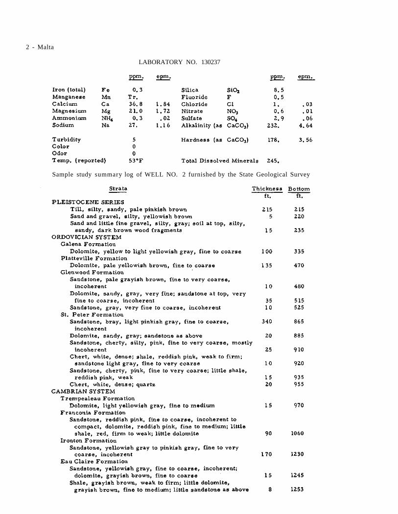
2 - Malta
LABORATORY NO. 130237
Sample study summary log of WELL NO. 2 furnished by the State Geological Survey

Illinois State Water Survey Bulletin 40 - Supplement II
MANLIUS Bureau County November 25, 1960
Water for the village of Manlius (374) is obtained from one well (No. 2).
WELL NO. 1, described in Bulletin 40, has been maintained for stand-by use for sev-eral years.
Correlated driller's log of WELL NO. 1 furnish-ed by the State Geological Survey
WELL NO. 2 was completed in 1950 to a depth of 268 ft. by Albrecht and Sons, Ohio,
and located 15 ft. east of Well No. 1, or approx-imately 1180 ft. N. and 1155 ft. W. of the S. E. corner of Section 15, T17N, R7E. The ground surface elevation at the well is 703. The well was cased with 8-in. pipe from the surface to 228 ft. followed by 20 ft. of 6-in. blank pipe and 20 ft. of 6-in. screen to the bottom of the well at 268 ft.
The permanent pump is an Aurora turbine rated at 135 gpm., connected to a 15-hp. U S electric motor.
A mineral analysis of a sample (Lab. No. 153662) collected Nov. 23, 1960 showed the wa-ter in Well No. 2 to have a hardness of 20 gr. per gal., total dissolved minerals of 411 ppm., and an iron content of 1.9 ppm.
There are 143 services. Pumpage is re-ported to average 50, 000 gpd.
LABORATORY NO. 153662

Illinois State Water Survey Bulletin 40 - Supplement II
MAPLE HILL IMPROVEMENT ASSOCIATION DuPage County November 26, 1960
A public water supply was installed in 1939 for the Maple Hill Improvement Association (est. 175).
WELL NO. 1 was completed in 1939 to a depth of 117 ft. by a Mr. Strong of Downer s Grove, and located just west of Downers Grove, or ap-proximately 5 ft. S. and 650 ft. W. of the N. E. corner of Section 13, T38N, R10E. The ground surface elevation at the well is 748. The well was cased with 6-in. pipe from the surface to 80 ft., below which the hole was finished 6 in. in diameter.
The pumping equipment consists of 98 ft. of 3 l/4-in. discharge pipe; Deming reciprocal pump, No. 58829, with a 10-in. stroke and rated at 1400 gal. per hr. at 205 ft. T.D.H.; 3-hp. Century electric motor.
On July 3, 1958 the nonpumping water level was 94 ft.
Well No. 1 is maintained for emergency use
only.
WELL NO. 2 was completed in 1954 to a depth of 158 ft. by DuPage Pump Sales Co., and located 10 ft. south of Well No. 1. The well was cased with 6-in. pipe to an unreported depth.
The pumping equipment consists of 140 ft. of 2-in. discharge pipe; 10-stage Reda submers-ible pump, rated at 43 gpm. at 205 ft. T.D.H.; 3-hp. electric motor.
On July 3, 1958, when pumping at 150 gpm. for 1/2 hr. , the drawdown was 8 ft. from a non-pumping water level of 94 ft.
A mineral analysis of a sample (Lab. No. 153759) collected Nov. 26, 1960 showed the water in Well No. 2 to have a hardness of 26.4 gr. per gal., total dissolved minerals of 574 ppm., and an iron content of 7. 4 ppm.
There are 50 services. Pumpage is esti-mated to average 9000 gpd.
LABORATORY NO. 153759

Illinois State Water Survey Bulletin 40 - Supplement II
MARENGO McHenry County April 30, 1958
One well is in service for the public water supply of the city of Marengo (3568).
WELL NO. 1 was reported in Bulletin 40 as abandoned and filled.
WELL NO. 2, described in Bulletin 40 as the shallow dug well constructed about 1938, has been retired and is maintained for emergency use only.
WELL NO. 3, formerly belonging to Borden Milk Co., was purchased by the city about 1955 or 1956. The well was drilled in 1951 to a depth of 1028 ft. by Varner Well Co., Dubuque, Iowa, and located on North Sponable St. south of West Rail-road St., or approximately 960 ft. S. and 1540 ft. W. of the N. E. corner of Section 35, T44N, R5E. The ground surface elevation at the well is 815. The well was cased with 26-in. pipe from the surface to 70 ft., with 18-in. pipe from the surface to 182 ft., and with 12-in. pipe from the surface to 538 ft. (cemented in). Below 538
ft. the hole was finished 12 in. in diameter to the bottom. When the well was completed the static water level was 91 ft. below the top of the casing (4 ft. above L. S. D. ).
The pumping equipment consists of 270 ft. of column pipe; Layne and Bowler turbine pump (No. 23294); 270 ft. of air line; 50-hp. Louis Allis electric motor.
On Apr. 30, 1958, when pumping at 300 gpm., the drawdown was 61 ft. from a nonpump-ing water level of 116 ft. below the pump base.
A mineral analysis of a sample (Lab. No. 127064) collected Nov. 27, 1951 showed the water in Well No. 3 to have a hardness of 18.2 gr. per gal., total dissolved minerals of 320 ppm., and an iron content of 0. 7 ppm.
Pumpage from Mar. 1, 1957 through April 1958 averaged 71, 000 gpd.
LABORATORY NO. 127064

2 - Marengo
Summary sample study log of City WELL NO. 3, formerly Borden Milk Co. well, furnished by the State Geological Survey

Illinois State Water Survey Bulletin 40 - Supplement II
MARTINTON Iroquois County June 23, 1960
A water supply was installed in 1959 for the village of Martinton (314). Water is obtained from one well.
WELL NO. 1 was completed in May 1959 to a depth of 265 ft. by J. P. Miller Artesian Well Co., Brookfield, and located at the east end of Thomas St., or approximately 930 ft. S. and 1680 ft. E. of the N. W. corner of Section 16, T28N, R12W. The ground surface elevation at the well is 630. The well was cased with 10-in. steel pipe to limestone at 148 ft., below which the hole was finished 10 in. in diameter.
The Driller reported that on May 8, 1959. when pumping for 8 hr. at 530 gpm. with test
pumping equipment, the drawdown was 13 ft. from a nonpumping water level of 9 ft. below the surface.
A partial analysis of a sample (Lab. No. 149533) collected May 8, 1959 showed the water in Well No. 1 to have a hardness of 15 gr. per gal., total dissolved minerals of 387 ppm., and an iron content of 1. 4 ppm.
The permanent pumping equipment includes a Peerless turbine rated at 280 gpm. connected to a 15-hp. U S electric motor.
Pumpage is estimated to average 15, 000 gpd.
LABORATORY NO. 149533

Illinois State Water Survey Bulletin 40 - Supplement II
MATTESON Cook County May 15, 1958
WELL NO. 1 of the Matteson (3225) public water supply has been equipped, since publica-tion of Bulletin 40, with a new Pomona turbine pump of 350 gpm. capacity and with power from a 25-hp. General Electric motor. This installa-tion was made in 1950.
WELL NO. 2 was completed for the village supply in 1956. It was drilled to a depth of 300 ft. by Wehling Well Works, Beecher, and located 1430 ft. S. and 100 ft. E. of the N. W. corner of Section 26, T35N, R13E, nearly l/2 mile south-west of Well No. 1. The ground elevation at the well is 700. The well was cased with 92 ft. of extra heavy wi. pipe, below which the bore hole was finished at 11 3/4 in. in diameter to the bot-tom at 300 ft.
In a production test by the Driller in May 1956, water was pumped for 10 hr . at a rate of 650 gpm. with a drawdown of 25 ft. from a static level of 20 ft. below the surface.
On May 15, 1958, after 5 min. pumping at 580 gpm., the drawdown was 6 ft.
The permanent pumping equipment installed about May or June 1956, includes a Pomona tur-bine pump, No. 484537, and a 40-hp. Fairbanks-Morse electric motor. An air line is installed but the length is not known.
A mineral analysis of a sample (Lab. No. 146780) collected May 15, 1958, after 5 min. pumping at a rate of 580 gpm., showed the water in Well No. 2 to have a hardness of 27.2 gr. per
gal . , total dissolved minerals of 661 ppm., and an iron content of 0. 5 ppm.
Pumpage from Mar. 6 to Dec. 31, 1957 inclusive, averaged 106, 300 gpd.
Summary sample study log of WELL NO. 2 fur-nished by the State Geological Survey
LABORATORY NO. 146780

Illinois State Water Survey Bulletin 40 - Supplement II
MAY STREET SUBDIVISION Will County October 10, 1958
A public water supply was installed about 1946 for the May Street Subdivision (est. 300). Two wells are in service, each pumping into the two interconnected distribution systems. The systems are owned and operated by the May Street Water Association.
WELL NO. 1 (May St.) was completed in 1946 to a depth of 165 ft. by J. P. Miller Artesian Well Co., Brookfield, and located on the east side of May St. between Nobes and Dellwood St., or approximately 1850 ft. S. and 680 ft. E. of the N. W. corner of Section 35, T36N, R10E. The ground surface elevation at the well is 638. The well was cased with 6-in. pipe into limestone at an unreported depth, and equipped with a Reda Red Jacket submersible pump, rated at 30 gpm. and powered by a 1 l/2-hp. electric motor.
A partial chemical analysis of a sample (Lab. No. 147931) collected Oct. 10, 1958 showed the water to have a hardness of 39 gr. per gal., total dissolved minerals of 861 ppm., and an iron content of 0. 7 ppm.
There are 42 services in this system, none metered, but serving the entire population.
WELL NO. 2 (Nobes St. ) was completed in 1948 to a depth of 200 ft. by Dreher and Schorie, Joliet, and located on the south side of Nobes St. between May and Brassel St., about 350 ft. northeast of Well No. 1, or approximately 1660 ft. S. and 990 ft. E. of the N. W. corner of Section 35. The ground surface elevation is 639. The well was cased into limestone at an unreported depth. When the well was completed the static water level was 62 ft. below the ground surface.
The well is equipped with a Reda Red Jacket submersible pump rated at 30 gpm., and powered by a 1 l/2-hp. electric motor.
A mineral analysis of a sample (Lab. No. 147932) collected Oct. 10, 1958 showed the water to have a hardness of 46. 5 gr. per gal., total dissolved minerals of 991 ppm., and an iron content of 1. 9 ppm.
There are 43 services on this system, none metered, but serving all the population.
Pumpage from the two distribution systems is estimated to average 18, 000 gpd.
LABORATORY NO. 147932

Illinois State Water Survey Bulletin 40 - Supplement II
MEADOWDALE SUBDIVISION Kane County April 23, 1958
Three wells are in service for the public water supply of Meadowdale Subdivision (est. 3400) located near Carpentersville. The system is owned and operated by the Meadowdale Corpora-tion.
WELL NO. 1 was completed in 1955 (?) to a depth of 247 ft. for L. W. Be singer & Associates, Subdivision Developers, and located about 1 1/2 miles east of Carpentersville, or approximately 1450 ft. N. and 1600 ft. E. of the S. W. corner of Section 13, T42N, R8E. The ground surface ele-vation at the well is 900. The well was cased with 12-in. pipe from the surface to 210 ft. pene-trating limestone. The Engineer later reported measuring the well depth at 200 ft.
When the well was completed the Driller reported pumping for 18 hr. at a rate of 125 gpm. with a drawdown of 20 ft. from a static water level of 145 ft. below the pump base.
The permanent pumping equipment consists of 170 ft. of 6-in. column pipe; 8-in., 10-stage Layne turbine pump, No. 34307, rated at 350 gpm. at 292 ft. T.D.H.; 10 ft. of suction pipe; 170 ft. of air line; 30-hp. U S electric motor.
WELL NO. 2 consists of 45 well points of 1 1/2 in. in diameter each and spaced 15 ft. apart. These were jetted-in in 1954 by the owners. The points are located in the subdivision close to the Fox River, The well points are not in service and reportedly there are no plans for their future use.
WELL NO. 3 was completed in Oct. 1955 to a depth of 72 ft. by Layne-Western Co., Aurora, for the owners, L. W. Besinger & Associates. The well is located northeast of Carpentersville, or approximately 1500 ft. S. and 400 ft. W. of the N. E. corner of Section 15. The ground surface elevation at the well is 800. The well was cas-ed with 16-in. pipe from the surface to 52 ft. followed by 20 ft. of 16-in. Layne shutter screen. The annulus outside the screen was gravel pack-ed.
A production test was reported by the Drill-er as of Oct. 18, 1955. After 8 hr. pumping at a rate of 1223 gpm., the drawdown was 21 ft. from a static water level of 18 ft. below the pump base.
The permanent pumping equipment consists of 45 ft. of 8-in. column pipe; 8 stages of Layne
turbine pump, No. 31881, rated at 1000 gpm. at 325 ft. T.D.H.; 50 ft. of air line; 100-hp. U S electric motor.
WELL NO. 4 was completed in Feb. 1957 to a depth of 177 ft. by Layne-Western Co. for L. W. Besinger & Associates.
Summary sample study log of WELL NO. 4 fur-nished by the State Geological Survey
The well is located 1230 ft. west of the center line of Route 25 and 70 ft. south of the center line of the Lake Marion Road, or approx-imately 1450 ft. S. and 1230 ft. W. of the N. E. corner of Section 14. This location is about 1 mile west of Well No. 3. The ground surface elevation at the well is 870.
The well was cased from the surface to 157 ft. with 18-in. steel pipe with welded joints,

2 - Meadowdale Subdivision
followed by 20 ft. of Armco iron shutter screen with No. 5 slot openings. The 8-in. annulus outside the screen was packed with 15 cu. yd. of pea gravel.
A production test was conducted by the Driller on Feb. 19, 1957, using a Layne test tur-bine set at 130 ft. An air line 130 ft. long was installed. Power was furnished by a Continental engine. After 8 hr. pumping at a rate of 1100 gpm., the drawdown was 11 ft. from a static wa-ter level of 69 ft. below the surface.
The permanent pumping equipment consists of 110 ft. of 10-in. column pipe; 15-in., 3-stage Layne turbine pump, No. 36704, rated at 1800 gpm.; 110 ft. of air line;150-hp. General Electric
motor. Also installed for auxiliary power, is a Johnston right angle gear drive, No. 27764, con-nected to an 8-cylinder Chrysler engine.
On Apr. 23, 1958, during pumping at 1800 gpm., the drawdown was 17 ft. from a nonpump-ing water level of 84 ft. below the pump base.
A mineral analysis of a sample (Lab. No. 146387) collected Apr. 23, 1958 showed the water in Well No. 4 to have a hardness of 23.6 gr. per gal., total dissolved minerals of 448 ppm., and an iron content of 1. 8 ppm.
Pumpage for the subdivision for Apr. 1958 was principally from Well No. 4 and averaged 630,000 gpd.
LABORATORY NO. 146387

Illinois State Water Survey Bulletin 40 - Supplement II
MELVIN Ford County July 29, 1959
Two wells are in service for the village of Melvin (559).
WELL NO. 1, described in Bulletin 40, was abandoned about 1950.
WELL NO. 2 was described in Bulletin 40 as being a failure.
WELL NO. 3, described in Bulletin 40, is maintained for emergency service by being pump-ed about once a week.
WELL NO. 4 was completed in June 1954 to a depth of 260 ft. by J. Bolliger and Sons, Fairbury, and located about 12 ft. south of Well No. 1, or approximately 1300 ft. S. and 1700 ft.
E. of the N. W. corner of Section 1, T24N, R8E. The ground surface elevation at the well is 805. The well is cased with 242 ft. of 8-in. pipe fol-lowed by 20 ft. of 8-in. Johnson Everdur screen having No. 12 slot openings.
A production test was conducted on June 9, 1954 by representatives of the Driller and the State Water Survey. After 5 1/2 hr. pumping at 153 gpm., the drawdown was 13 ft. from a non-pumping water level of 118 ft. Ten min. after the pump was stopped, the water level had re-covered to 118 1/2 ft.
There are 240 services and pumpage is estimated to average 45, 000 gpd.
Illinois State Water Survey Bulletin 40 - Supplement II
METROPOLIS Massac County March 4, 1958
Five wells are in service for the public water supply of the city of Metropolis (7339).
WELL NO. 1 (old well) is described in Bul-letin 40. The present pumping equipment report-edly consists of 70 ft. of column pipe; 5-stage Worthington turbine pump, rated at 650 gpm.; 10 ft. of suction pipe; 25-hp. electric motor.
WELL NO. 2 (new well) is described in Bulletin 40. The present pumping equipment reportedly consists of 100 ft. of 8-in. column pipe; 9-stage Worthington turbine pump, 9 ft. 11 in. long and rated at 1000 gpm.; 20 ft. of suction pipe; 40-hp. electric motor.
WELL NO. 3 was completed in July 1950 to a depth of 286 ft. by Diehl Pump and Supply Co., Louisville, Ky., and located east of the munici-pal electric plant, about 180 ft. southwest of Well No. 2, or approximately 800 ft. S. and 1000 ft. W. of the N. E. corner of Section 11, T16S, R4E. The elevation of the ground surface at the well is 3 10. The well is cased with 12-in. steel pipe to limestone at 261 ft., below which the hole was finished at 12 in. in diameter.
The well is equipped with a Cook turbine pump, rated at 1800 gpm.; 180 ft. of l/4-in. air line; 40-hp. electric motor.
A mineral analysis of a sample (Lab. No. 145940) collected Mar. 4, 1958 showed the water in Well No. 3 to have a hardness of 12. 3 gr. per gal., total dissolved minerals of 233 ppm., and an iron content of 0. 3 ppm.
WELL NO. 4 (Metropolis Ice and Fuel Co. Well) was put in service for the city as an aux-iliary supply in the summer of 1952. The well was formerly owned by the C. I. P. S. and is now the property of Walter Owens, operator of the Metropolis Ice and Fuel Co. The well was re-portedly drilled to a depth of 400 ft. at the south edge of town just east of the main street running through the old business section. The well is casedwith 8-in. pipe from 4 ft. above ground level.
The pumping equipment includes a Pomona
turbine pump, rated at 600 gpm., and a 40-hp. electric motor.
WELL NO. 5 (Hospital Well) was completed inMayl955 to a depth of 400 ft. by Layne-Western Co., Kirkwood, Mo., and located about 1 1/2 miles northwest of Well No. 2, about 100 yards north of U. S. Highway 45 near the Massac Me-morial Hospital, or approximately 1200 ft. N. and 1750 ft. E. of the N. W. corner of Section 35, T15S, R4E. The elevation of the ground surface at the well is 360. The well was cased with 16-in. welded pipe from the surface to 243 ft. 4 in.; with 12-in. threaded and coupled pipe from the surface to 335 ft., and with 10-in. threaded and coupled pipe from 308 ft. to 398 ft., the bottom 66 ft. being slotted. The annulus between the 16-in. and 12-in. casings was pressure grouted with 205 sacks of cement. During the drilling, the first static water level was 58 ft. below the surface. After bailing and surging to develop the well the static water level was 35 ft.
A production test was conducted on May 16, 1955 by representatives of the Driller, the State Water Survey, and J. W. Blankenship, Consulting Engineer. For the test the well was equipped with a Layne turbine test pump set at 160 ft. and powered by a gasoline engine. An air line, 159 ft. in length, was in place. After 6 hr. pumping at a rate of 305 gpm., the drawdown was 54 ft. from a static water level of 35 ft. below the top of the casing. Within 5 min. after the test was stopped, the water level had recovered to 39 ft.
A partial chemical analysis of a sample (Lab. No. 137686) collected May 16, 1955, after 6 hr. pumping at a rate of 300 gpm., showed the water in Well No. 5 to have a hardness of 12.9 gr. per gal., total dissolved minerals of 266 ppm., turbidity of 346 ppm., and an iron content of 11 ppm.
The permanent pump installation includes a Fairbanks-Morse turbine pump, rated at 500 gpm.; an air line of unreported length; 60-hp. Fairbanks-Morse electric motor.
Pumpage in 1958 averaged 800, 000 gpd.

2 - Metropolis
LABORATORY NO. 145940

Illinois State Water Survey Bulletin 40 - Supplement II
MILAN Rock Island County May 5, 1959
The village of Milan (3065) has three wells. Wells No. 1 and 2 pump into the old reserve tank and Well No. 3 furnishes the principal supply.
WELLS NO. 1 and 2, described in Bulletin 40, are maintained for emergency use only. New pumping equipment was installed in Well No. 2 about Nov. 1956, consisting of 210 ft. of 5-in. column pipe; 7 l/2-in., 14-stage American Well Works turbine pump, rated at 120 gpm. and hav-ing an over-all length of pump and column of 225 ft.; 210 ft. of l/4-in. air line; 15-hp. electric motor.
In Nov. 1956, after 3 hr. pumping at 115 gpm., the drawdown was reportedly 200 ft. from a nonpumping water level of 25 ft. below the pump base.
A partial chemical analysis of a sample (Lab. No. 149618) collected May 5, 1959 showed the water in Well No. 2 to have a hardness of 20.4 gr. per gal., total dissolved minerals of 399 ppm., and an iron content of 4. 2 ppm.
WELL NO. 3 was completed in Oct. 1954 to a depth of 453 ft. by Quad City Drilling Co., Milan, and located on U. S. Highway 67 south of town about 1 mile south of Well No. 2, or approx-imately 650 ft. S. and 590 ft. W. of the N. E. corner of Section 26, T17N, R2W. The ground surface elevation at the well is 600. The well was cased with 12-in. pipe from the surface to
49 ft. 10 in. and 10-in. pipe from the surface to 159 ft. 11 in. The bore hole was finished 12 in. in di-ameter to 260 ft. and 10 in. in diameter from 260 to 453 ft. at the bottom of the hole. The annulus outside the 10-in. casing was packed and cemented from the bottom of the casing to the surface.
A production test was conducted on Jan. 25-26, 1955 by representatives of the Driller, the State Water Survey, and Interstate Engineer-ing Co. For the test, a 7 l/2-in., 13-stage Peer-less turbine pump was set at 310 ft. and belt-driven from a Red Seal gasoline engine. After 12 hr. pumping at a rate of 310 gpm., the drawdown was 33. 4 ft. from a nonpumping water level of 74.1 ft. below the top of the casing (1.2 ft. above ground level). One hr. after pumping was stop-ped, the water level had recovered to 86. 5 ft.
The permanent pumping equipment con-sists of 5-in. column pipe; 5 l/4-in., 8-stage Fairbanks-Morse turbine pump, PT1202, rated at 250 gpm.; 127 ft. of l/4-in. air line; 30-hp. electric motor.
A mineral analysis of a sample (Lab. No. 149562) collected May 5, 1959 showed the water in Well No. 3 to have a hardness of 19. 8 gr. per gal., total dissolved minerals of 385 ppm., and an iron content of 0. 3 ppm.
Pumpage for a 6-mo. period in 1958 was estimated to average 288, 000 gpd.
LABORATORY NO. 149562

Illinois State Water Survey Bulletin 40 - Supplement II
MISSISSIPPI PALISADES STATE PARK Carroll County September 25, 1957
Water for the Mississippi Palisades State Park is obtained from three wells and one spring, located in the three sections of the Park.
MAIN SECTION
WELL NO. 1 was completed to a depth of 285 ft. in 1933 by Davis and Blackman, Preston, Iowa, and located approximately 1050 ft. N. and 430 ft. E. of the S. W. corner of Section 27, T25N, R3E. The ground elevation at the well is 655. The well was cased with 6-in. pipe to 84 ft. 10 in. and finished as a 6-in. hole to the bot-tom.
The well was equipped with a Fairbanks-Morse cylinder pump with power from a 2-hp. Fairbanks-Morse electric motor.
A partial analysis of a sample (Lab. No. 88745) collected Aug. 22, 1940 showed the water in this well to have a hardness of 17. 6 gr. per gal., total dissolved minerals of 316 ppm., and an iron content of 0. 5 ppm.
Well No. 1 in the Main Section was aban-doned and sealed in 1951, according to a State Department of Public Health report.
WELL NO. 2 was completed to a depth of 515 ft. in 1935 by C. H. Coad and Son, Apple River, and is located in the easterly portion of the Section on a hill, approximately 2150 ft. N. and 150 ft. W. of the S. E. corner of Section 33, T25N, R3E. The ground surface elevation at the well is 830. The casing record is not avail-able.
The well is equipped with a Deming cylinder pump, connected to a 4-hp. General Electric motor.
A partial analysis of a sample (Lab. No. 88746) collected Aug. 22, 1940 showed this wa-ter to have a hardness of 16.1 gr. per gal., total dissolved minerals of 306 ppm., and an iron content of 0. 1 ppm.
Well No. 2 is in service. Water is pump-ed into a small concrete collecting reservoir from which it flows by gravity to lower sections of the Park.
WELL NO. 3 was completed to a depth of 560 ft. in Oct. 1951 by Varner Well Co., Dubuque,
Iowa, and located about 17 ft. east of old Well No. 1, approximately 1050 ft. N. and 450 ft. E. of the S. W. corner of Section 27. The well was cased with 10-in. pipe from 1 ft. above to 53 ft. below the surface and with 6-in. pipe from 1 ft. above to 266 ft. below the surface. The annulus between the casings was cement grouted.
Sample study summary log of WELL NO. 3, Main Section, furnished by the State Geological Survey
A production test was conducted on Oct. 22-23, 1951 by representatives of the Driller, the State Water Survey, and the State Department of Architecture and Engineering. For test pur-poses the well was equipped with a Peerless Hi-Lift turbine pump, set at 145 ft. below the top of the casing. Power was from a U S electric mo-tor. After 24 hr. pumping at a rate of 40 gpm., the drawdown was 24 ft. from a nonpumping wa-ter level of 50 ft. below the top of the casing.
A mineral analysis of a sample (Lab. No. 126751) collected Oct. 23, 1951, after 24 hr. pump-ing at 40 gpm., showed the water in Well No. 3 to have a hardness of 16. 5 gr. per gal., total dissolved minerals of 287 ppm., and an iron content of 0. 5 ppm.
The well is equipped with a Peerless tur-bine pump, rated at 25 gpm., connected to a 7

2 - Mississippi Palisades State Park
1/2-hp. electric motor.
Well No. 3 is in service.
NORTH SECTION
WELL NO. 1 was completed, according to the State Department of Public Health, in 1940 to a depth of 445 ft. by J. P. Miller Artesian Well Co., Brookfield, and located near the cen-ter of the cabin area. The well was cased with 6-in. pipe to 387 ft., below which the hole was finished 6 in. in diameter to the bottom.
Pumping equipment includes a Fairbanks-
Morse Pomona turbine connected to a 2-hp. elec-tric motor.
MILLERS HOLLOW SECTION
Water is obtained from springs located approximately 1050 ft. N. and 900 ft. W. of the S. E. corner of Section 28, T25N, R3E.
A short partial analysis of a sample (Lab. No. 104677) collected Oct. 25, 1945 showed the water from one of the springs to have a hardness of 19 gr. per gal., total dissolved minerals of 374 ppm., and a trace of iron.
LABORATORY NO. 126751

Illinois State Water Survey Bulletin 40 - Supplement II
MONTGOMERY Kane County July 30, 1958
Two wells are in service for the village of Montgomery (2122).
WELL NO. 1 is described in Bulletin 40. The well has been maintained only as a stand-by unit since 1958.
WELL NO. 2 was completed in 1949 to a depth of 718 ft. by Layne-Western Co., Aurora, and located south of Well No. 1, or approximately 1825 ft. N. and 1460 ft. W. of the S. E. corner of Section 32, T38N, R8E. The ground surface ele-vation at the well is 642.
The well was cased with 20-in. pipe from the surface to 25 ft., with 18-in. pipe from the surface to 200 ft., and with 14-in. pipe from the surface to 221 ft. Below this depth the diameter of the hole was not reported.
The pumping installation consists of 250 ft. of column pipe; Aurora turbine pump, No. 44635 (?), rated at 240 gpm. against 280 ft. T.D.H.; 250 ft. of air line; 25-hp. U S electric motor.
Since July 10, 1958, when Well No. 3 went into service, Well No. 2 has been maintained as a stand-by unit.
WELL NO. 3 was completed to a depth of 1336 ft. in Nov. 1957 by Layne-Western Co. and located about 3/8 mile east of Well No. 2, or approximately 1350 ft. N. and 750 ft. E. of the S. W. corner of Section 33. The ground surface elevation at the well is 63 3.
A production test was conducted on Nov. 6, 1957 by representatives of the Driller. The well was cased with 26-in. pipe from the surface to 36 ft., with 20-in. pipe from the surface to 539 ft., and with a 16-in. liner from 860 to 1000 ft.
The 20-in. casing was cemented in.
The well was shot with 150-lb. explosives at depths of 1310, 1280, 1250 and 1230 ft.
A production test was conducted by repre-sentatives of the Driller on Nov. 6, 1957. After 23 hr. pumping at a rate of 1022 gpm., the draw-down was 120 ft. from a static water level of 253 ft. below the top of the casing (1 ft. above ground level). For the teat, a Pomona turbine test pump
was installed.
On July 30, 1958, after the permanent pump was installed, water was pumped for 1/4 hr. at a rate of 1150 gpm. with a drawdown of 83 ft. from a nonpumping water level of 250 ft. below the top of the casing.
The pumping installation consists of 450 ft. of 8-in. column pipe; 12-in., 9-stage Byron Jack-son submersible pump, No. 346708, rated at 1000 gpm. against 550 ft. T.D.H.; 450 ft. of air line; 200-hp. electric motor.
A mineral analysis of a sample (Lab. No. 147410) collected July 30, 1958, after 15 min. pumping at 1150 gpm., showed the water in Well No. 3 to have a hardness of 15.7 gr. per gal., total dissolved minerals of 466 ppm., and a trace of iron.
WELL NO. 4 was completed in 1958 to a depth of 1353 ft. by Layne-Western Co. and lo-cated near the All Steel Products Plant about 3/4 mile southwest of Well No. 3, or approxi-mately 1475 ft. S. and 2115 ft. W. of the N. E. corner of Section 32.
The well was cased with 26-in. pipe from the surface to 25 ft. and with 20-in. pipe cement-ed in, from the surface to 553 ft., below which the hole was finished at 19 1/4 in. in diameter to the bottom. The well was shot with four 150-lb. charges at depths of 1330, 1305, 1285 and 1250 ft.
A production test was conducted by the Driller on Jan. 22, 1958. For the test a Layne turbine test pump was used. After 16 hr. pump-ing at a rate of 1326 gpm., the drawdown was 142 ft. from a static water level of 250 ft. below the top of the casing.
A partial chemical analysis of a sample (Lab. No. 145594) collected Jan. 22, 1958, after 16 hr. pumping at 1326 gpm., showed the water in Well No. 4 to have a hardness of 15.2 gr. per gal., total dissolved minerals of 406 ppm., and an iron content of 0.4 ppm.
The well is not equipped for pumping and is not ready for service,
Metered pumpage from July 10 to 30, 1958, averaged 200,000 gpd.

2 - Montgomery
Sample study summary log of WELL NO. 3 furnished by the State Geological Survey

Montgomery - 3
LABORATORY NO. 147410

Illinois State Water Survey Bulletin 40 - Supplement II
MONTICELLO Piatt County November 22, 1960
Three wells are in service for the city of Monticello (3219). Three old wells that were drilled between 1892 and 1912 were described in Bulletin 40 as having been abandoned in 1922 and 1935.
WELL NO. 1, according to the present system of numbering of the municipal wells, is described in Bulletin 40 and is presently in serv-ice.
WELL NO. 2, described in Bulletin 40, is in service.
WELL NO. 3 was completed in June 1958 to a depth of 263 ft. by Layne-Western Co., Aurora, and located at the pumping station, 100 ft. north of the old wells, or approximately 765 ft. N. and 1418 ft. E. of the S. W. corner of Section 7, T18N, R6E. The ground surface ele-vation at the well is 668. A 34-in. hole was drilled from the surface to the bottom at 263 ft. A 26-in. outer steel casing was set from the sur-face to 25 ft. and a 12-in. inner casing was set from the surface to 243 ft. followed by 20 ft. of Layne stainless steel shutter screen. The annu-lus outside the screen and 12-in. casing was
packed with 65 cu. yd. of gravel.
A production test was conducted on June 9-10, 1958 by representatives of the Driller, the State Water Survey, City officials, and Engi-neering Service Corporation, Consulting Engi-neers. After 24 hr. pumping at 1005 gpm., the drawdown was 13 ft. from a nonpumping water level of 34 ft. (air line). Six min. after the test was stopped, the water level had recovered to 35 ft.
The permanent pumping equipment consists of a 10-in., 5-stage turbine pump set with the bottom of the bowls at 120 ft. and the pump rated at 750 gpm. at 150 ft. T.D.H.; 10 ft. of suction pipe; 40-hp. electric motor with auxiliary power from a 59-hp. Continental gas engine, Type M-330.
A mineral analysis of a sample (Lab. No. 153660) collected Nov. 22, 1960 showed the water in Well No. 3 to have a hardness of 15. 5 gr. per gal., total dissolved minerals of 356 ppm., and an iron content of 1.6 ppm.
There are 1150 services, all metered. Pumpage is reported to average 600, 000 gpd.
LABORATORY NO. 153660

Illinois State Water Survey Bulletin 40 - Supplement II
MORRIS Grundy County October 14, 1958
Three wells are in service for the city of Morris (7935).
WELLS NO. 1 and 2, as described in Bul-letin 40, have been abandoned and sealed.
WELL NO. 3 is described in Bulletin 40. In Aug. 1951 the Layne pump was removed and rehabilitated after a break in the oil tube had permitted a considerable amount of oil to enter the well. After repairs, the reconditioned pump was restored at the same setting. Eight 10-ft. lengths of pump column and twenty-one 5-ft. lengths of shaft tubing were replaced with new parts. A new 200-ft. length of air line was in-stalled. While the pump was out, the static wa-ter level was 52. 2 ft.
Well No. 3 is in service.
WELL NO. 4 is described in Bulletin 40. In June 1955 the Layne pump was removed for repairs, due to holes in the column pipe and corrosion of the threads of several sections of the column. The old 12-in., 3-stage pump, Layne, No. 9091, was reinstalled in Sept. 1955 with 160 ft. of 8-in. column pipe; 10 ft. of,8-in. suction pipe; new bowls; 170 ft. of air line; self-reading gage; the 50-hp. U S motor was rein-stalled. The static water level was 59.1 ft. The depth of the well was measured 1492 ft. by Layne-Western workmen.
Well No. 4 is in service.
WELL NO. 5 was completed in 1954 to a depth of 1462 ft. by Milaeger Well Drilling Co., Milwaukee, Wis., and located about 3/4 mile north of Well No. 4, or approximately 1800 ft. N. and 2250 ft. W. of the S. E. corner of Sec-tion 4, T33N, R7E. The ground surface eleva-tion at the well is 505.8. The hole and casing record is shown in Table A.
TABLE A
Hole Record
24-in. from surface to 63 ft. 23-in. from 63 ft. to 3 12 ft. 17-in. from 312 ft. to 1462 ft.
Casing Record
24-in. pipe from surface to 63 ft. 18-in. pipe from surface to 312 ft. 1 6-in. liner from 280 ft. to 800 ft. The 18-in. pipe was cement grouted in place from 312 ft. to the surface. The 16-in. liner was perforatedbe-tween depths of 425 and 600 ft.
The well was shot with four 150-lb. charges of 80% Hi-velocity gelatinat depths of 1390, 1370, 1340 and 1320 ft. The sand dislodged by the ex-plosions was removed after shooting.
A production test was conducted on May 11-12, 1954 by representatives of the Driller, the State Water Survey, and Walter E. Deuchler Co., Consulting Engineers. For test purposes, the well was equipped with a 12-in., 9-stage turbine test pump, 8. 5 ft. long and 11 ft. of tail pipe; 303 ft. of air line; electric motor. The top of the bowl section was set at a depth of 303 ft. Water levels in city wells No. 3 and 4 were measured on May 12 and 13. These and previous levels obtained from State Water Survey files are shown in Table B.
After 24 hr. pumping on May 11-12 at a rate of 1470 gpm., the drawdown was 150 ft. from a nonpumping water level of 35 ft. below the top of the casing. Twenty-two min. after pumping was stopped, the water level had recovered to 74 ft. and at 7:25 A. M. the following day or 13 hr. after pumping was stopped, the water level had

2 - Morris
recovered to 43. 5 ft.
On Mar. 4, 1955 the pump house was not yet constructed. The static water level in Well No. 5 was 49 ft.
In July 1955 a drawdown was reported in Well No. 4 when Well No. 5 was pumping. This was shortly after Well No. 5 had been placed in service.
On Oct. 14, 1958, after l/4 hr. pumping at 900 gpm., the drawdown was 193 ft. from a non-pumping water level of 46 ft. below the pump base.
The pumping equipment in Well No. 5 con-sists of 220 ft. of 10-in. column pipe (a heavy
pipe with two coats of bitumastic paint); 15-in., 3-stage Layne turbine pump (No. 29137), 4 ft. 9 in. long and rated at 1300 gpm. at 254 ft. T.D.H.; 10 ft. of 10-in. suction pipe; 220 ft. of copper air line; 125-hp. U S electric motor.
A partial chemical analysis of a sample (Lab. No. 147974) collected Oct. 14, 1958, after 15 min. pumping at a rate of 900 gpm., showed the water in Well No. 5 to have a hardness of 15.2 gr. per gal., total dissolved minerals of 419 ppm., and an iron content of 0. 3 ppm.
Pumpage from Aug. 1957 through Apr. 1958 was reported to average 825, 000 gpd.
Pumpage in July 1958 was reported to av-erage 870,000 gpd.
TABLE B

Morris - 3
LABORATORY NO. 147974

Illinois State Water Survey Bulletin 40 - Supplement II
MOUND PUBLIC WATER DISTRICT St. Clair County August 3, 1958
A well was completed for Mound Public Water District in Aug. 1958. The District ex-tends over approximately 400 acres located on the south side of U. S. Highway 40 about 2 miles west of Collinsville and l/4 mile east of Black Lane.
WELL NO. 1 was completed in July 1958 to a depthof 90 ft. by Layne-Western Co., St. Louis, Mo., and located 1380 ft. S. and 1450 ft. W. of the N. E. corner of Section 1, T2N, R9W. The well was located at the site of a test hole which had been drilled a week previous. The well is cased with 80 ft. of 8-in. pipe and 10 ft. of Layne stainless steel shutter screen, having No. 5 slot openings. The hole had been drilled 30 in. in diameter to a depth of 92 ft. but the bottom of the screen was set at 90 ft. due to the fine sand at that depth.
The casing is joint-welded pipe with the top 0. 5 ft. above the ground surface elevation of 418. It was intended to extend the casing top to 2 ft. or more above the ground level. The annu-lus outside the screen and casing was filled with 14 tons of Meramec gravel up to 40 ft. Fine sand was then packed in the annulus from 40 ft. up to 15 ft. and clay was packed in the upper 15 ft.
A production test was conducted on July 29-30, 1958 by representatives of the Driller, Cald-well-Rhoads Co., Consulting Engineers, and the State Water Survey. For test purposes the well was equipped with a 3-stage Johnston turbine
pump with the bottom of the bowls set at 50 ft. Power was furnished from a gasoline engine connected to the pump by a drive shaft. A 48 1/2-ft. air line was installed for measuring wa-ter levels. After 24 hr. pumping at a rate of 336 gpm., the drawdown was 9 ft. from a static wa-ter level of 8.5 ft. below the top of the casing. Two min. after pumping was stopped, the water level had recovered to 8. 5 ft.
A partial analysis of a sample (Lab. No. 147294) collected July 30, 1958, after 19 hr. pumping at 336 gpm., showed the water to have a hardness of 495 ppm., total dissolved miner-als of 525 ppm., and an iron content of 3. 8 ppm.
Correlated driller's log of WELL NO. 1 furnish-ed by the State Geological Survey
LABORATORY NO. 147294

Illinois State Water Survey Bulletin 40 - Supplement II
Since publication of Bulletin 40, one addi-tional well has been drilled for Mount Prospect (18, 906). Well No. 1 was abandoned and plugged; Well No. 2 is maintained for stand-by use; and Wells No. 3, 4 and 5 furnish the village supply.
WELL NO. 1 was acidized with 1000 gal. in Aug. 1950 and new pumping equipment was in-stalled. By Dec. 23, 1955 the well had been abandoned and plugged.
WELL NO. 2 was equipped in 1953 with 120 ft. of 4-in. column pipe; 6-in., 10-stage Peer-less turbine pump, No. 107644, rated at 100 gpm. against 135 ft. T.D.H.; 40 ft. of 4-in. suction pipe; 120 ft. of air line; 7 l/2-hp. U S electric motor.
In Dec. 1953, during pumping at a rate of 100 gpm., the drawdown was 100 ft. from a non-pumping water level of 37 ft. below the pump base (elev. 672).
Well No. 2 has been maintained for stand-by use, since 1957.
WELL NO. 3 is now equipped with 550 ft. of 8-in. column pipe; 12-in., 8-stage Peerless turbine pump (No. 109343); 10 ft. of 8-in. suction pipe; 556 ft. of air line; 150-hp. U S electric mo-tor.
On Aug. 31, 1958 the nonpumping water level was 408 ft. below the pump base and, dur-ing pumping to the system, the drawdown was 86 ft.
WELL NO. 4 is now equipped with 500 ft. of 8-in. column pipe; 10-in., 13-stage Fairbanks-Morse turbine pump, No. 3901, rated at 500 gpm.; 10 ft. of 8-in. suction pipe; 500 ft. of air line; 125-hp. U S electric motor.
On Aug. 31, 1958, during pumping to the system, the drawdown was 46 ft. from a non-pumping water level of 430 ft. below the pump base (elev. 693).
WELL NO. 5 was completed to a depth of 1822 ft. in Jan. 1955 by S. B. Geiger & Co., Chicago, and is located northeast of the inter-section of Emerson Ave. and Highland St., or approximately 800 ft. S. and 2300 ft. W. of the N. E. corner of Section 34, T42N, R11E. This is about 1 mile east of Well No. 3. The ground
MOUNT PROSPECT Cook County October 6, 1958
elevation at the well is 673.
The hole and casing record is shown in Table A.
TABLE A
Hole Record
24-in. to 442 ft. 17-in. to 1190 ft. 16-in. to 1583 ft. 12-in. to 1822 ft.
Casing Record
24-in. od. from surface to 130 ft. 7 in. 18-in. od. from surface to 442 ft. 10 in. 16-in. od. liner from 1008 to 1190 ft. The annulus outside the 18-in. casing was fill-ed with cement grout to a depth of 442 ft. 10 in. using 740 bags of cement.
When the well was completed in Feb. 1955, a production test was conducted by represent-atives of the Driller and the State Water Survey. After 24 hr. pumping at a rate of 910 gpm., the drawdown was 171 ft. from a nonpumping water level of 246 ft. below the top of the casing (2 ft. above the ground surface). Following the first test, it was decided to conduct a second test with a pump of larger capacity; however, when the pump was removed, it was found that sand had filled the hole up to 1660 ft. The hole was cleaned out with considerable difficulty because sand kept rolling in. One 200-lb. shot of nitrogen-gel was exploded with the bottom of the shot at 1670 ft. After several cu. yd. had been re-moved, a pump of larger capacity was installed and on Apr. 12 a second test was run. After a few min. pumping at a high rate, the rate drop-ped to 570 gpm. with a considerable amount of mud and sand in the water. Upon removing the pump, it was found that an impeller was bro-ken and that sand had again filled the well up to 1262 ft.
On May 10th, after the sand had been clean-ed out, a third test was run for 3 hr. at a rate of 570 gpm. with sand in the water at the end of the period. The pump was then operated at high speed for short periods with the sand present in the water. The test was discontinued and the well surged for a 15-hr. period in order to draw all loose sand possible into the bore hole.

2 - Mount Prospect
After removing a sand bridge between 1270 and 1330 ft. and also a 20-ft. fill of sand in the bottom of the well, a fourth test was started on May 14th, with the same pump as used in the previous tests, but terminated when the main pump bearing failed after 3 hr. pumping.
A production test was then conducted on May 15-16 by representatives of the Driller, Consoer, Townsend and Associates, Consulting
. Engineers, and the Village. After 24 hr. pump-ing at a rate of 1207 gpm., the drawdown was 160 ft. from a nonpumping water level of 295 ft. The water was reported clear at the end of the test.
The permanent pumping equipment in Well No. 5 includes 550 ft. of 10-in. column pipe; 12-in., 10-stage Peerless turbine pump, No. 113960, rated at 1200 gpm.; 10 ft. of 10-in. suction pipe; 550 ft. of air line; 750-hp. Ideal Electric motor.
A mineral analysis of a sample (Lab. No. 146788) collected June 2, 1958, after 10 min. pumping at a rate of 1200 gpm., showed the wa-ter in Well No. 5 to have a hardness of 15. 3 gr. per gal., total dissolved minerals of 453 ppm., and an iron content of 0. 6 ppm,
Pumpage in July 1958 was reported to av-erage 1. 4 mgd.
LABORATORY NO. 146788

Mount Prospect - 3
Sample study summary log of WELL NO. 5 furnished by the State Geological Survey

Illinois State Water Survey Bulletin 40 - Supplement II
Four wells are in service for the city of Mt. Pulaski (1689).
WELLS NO. 1 and 2, described in Bulletin 40, are in service. A production test was con-ducted on the two wells on Dec. 8, 1953. The test was conducted by pumping Well No. 2 (East Well) which was equipped to measure discharge, and observing the drawdown in Well No. 1 (West Well) which was equipped with an air line. The wells are 27 ft. apart. The rate of production, as determined in the test compared favorably with the rate of production observed when the wells were rehabilitated in 1932, at which time water was pumped at 180 gpm. for 4 hr. When pumping at 200 gpm., the water was drawn down below the 50 ft. length of air line. The water level in 1932 was reported to be 24 ft. 10 in. be-low floor level as compared with 20 ft. 7 in. in the 1953 test.
WELL NO. 3 was completed in Mar. 1954 to a depth of 104 ft. by Sims Drilling Co., Cham-paign, and located 400 ft. north of Wells No. 1 and 2 at the pumping station, or approximately 740 ft. S. and 1567 ft. E. of the N. W. corner of Section 14, T18N, R2W. The land surface eleva-tion at the well is 660. The well was cased with 85 ft. of 16-in. outer pipe and with 84 ft. of 8-in. inner pipe from 2 ft. above ground level, follow-ed by 20 ft. of 8-in. screen with No. 60 slot openings. The annulus outside the 8-in. screen and casing was gravel packed. The Driller re-ported a sand formation from 20 ft. to the bottom of the well.
A production test was conducted on Mar. 10, 1954 by representatives of the Driller, the State Water Survey, and the City officials. For the test a Pomona turbine test pump was installed with the bottom of the suction set at 77 ft. 6 in. Power was furnished from a Ford industrial gas engine. After 4 l/2 hr. pumping at a rate of 96 gpm., the drawdown was 21.2 ft. from a static water level of 47. 6 ft. Pumping was continued for 1 hr. at a rate of 132 gpm. but the drawdown was below the air line. Five min. after the pump was stopped, the water level had recovered to 49 ft.
The permanent pump is a 10-stage Fair-banks-Morse Pomona turbine, 10 ft. long and rated at 125 gpm. The pump is set at 80 ft. and
MT. PULASKI Logan County August 12, 1960
is followed by 10 ft. of 5-in. suction pipe. Power is furnished from a 10-hp. Fairbanks-Morse e-lectric motor.
A mineral analysis of a sample (Lab. No. 152584) collected June 27, 1960 showed the water in Well No. 3 to have a hardness of 32. 2 gr. per gal., total dissolved minerals of 630 ppm., and a trace of iron.
WELL NO. 4 (60-1) was completed in Aug. 1960 to a depth of 34 ft. by J. P. Miller Artesian Well Co., Brookfield, and located at the site of Test Well No. 1, along Salt Creek, or approxi-mately 1480 ft. N. and 2640 ft. E. of the S. W. corner of Section 35, T19N, R2W. The land sur-face elevation at the well is 585. (Test Well No. 1 had been drilled in Sept. 1959 following an elec-trical earth resistivity survey by the State Geo-logical Survey. The survey was made along Salt Creek about 3 miles north of the pump station).
Well No. 4 was cased with 10-in. pipe from 4. 3 ft. above to 27 ft. below land surface, follow-ed by 7 ft. of 10-in. stainless steel screen to the bottom at 34 ft. A production test was conducted on Aug. 3-5, 1960 by representatives of the Drill-er, City officials, State Water Survey, and Craw-ford, Murphy and Tilly, Consulting Engineers. For test purposes the well was equipped with 25 ft. of 4-in. column pipe; 5 5/8-in. Peerless tur-bine test pump, 6 ft. 11 1/4 in. long. After 45 hr. pumping at 100 gpm., the drawdown was 2. 7 ft. from a nonpumping water level of 15. 9 ft.
During the test, water levels were noted in three observation wells. The data are shown in Table A.
TABLE A
There are 650 services, 90% of which are metered. Pumpage is estimated to average 75,000 gpd.

2 - Mt. Pulaski
LABORATORY NO. 152 584

Illinois State Water Survey Bulletin 40 - Supplement II
A public water supply was being installed in Oct. 1958 for the village of Muddy (95).
WELL NO. 1 was completed in 1958 to a depth of 100 ft. by Quentin Richey, Carrier Mills, and located approximately 1500 ft. N. and 2500 ft. E. of the S. W. corner of Section 2, T9S, R6E. The ground surface elevation at the well is 360.
The well was cased with 7-in. pipe to 32 ft., below which the hole was finished in lime-stone and shale at 6 1/2 in. in diameter to the bottom at 100 ft.
A production test was conducted on Oct. 21, 1958 by representatives of the Driller, the
MUDDY Saline County October 21, 1958
State Water Survey, and the Village officials. For test purposes the well was equipped with a 5-hp. jet pump. A 65-ft. air line was installed. After 7 hr. pumping at a rate of 40 gpm., the drawdown was 58. 9 ft. from a static water level of 13. 5 ft. One hr. after the pump was stopped, the water level had recovered to 27. 7 ft.
A mineral analysis of a sample (Lab. No. 148016) collected Oct. 21, 1958, after 7 hr. pump-ing at 40 gpm., showed the water in Well No. 1 to have a hardness of 30.4 gr. per gal., total dissolved minerals of 969 ppm., and an iron content of 0. 4 ppm.
The distribution system had not yet been installed.
LABORATORY NO. 148016

Illinois State Water Survey Bulletin 40 - Supplement II
Public water supply for the village of Mul-berry Grove (745) is obtained from two wells.
WELL NO. 1, described in Bulletin 40, was acidized in Apr. 1954. During the 3-day period, while the well was out of service, water was pumped directly from a nearby creek to the iron removal treatment plant, using the jet pump from Well No. 2. The acidizing was reported to im-prove the yield of Well No. 1 considerably.
WELL NO. 2 was drilled in 1951 to a depth of 38 ft. by Smith Drilling Co., Farina, and lo-cated 11 ft. west of the Well No. 1 pump house. The well was reportedly cased with 8-in. pipe from 1 ft. above the ground surface to the bottom of the well. A 3-in. suction pipe was installed from 5 ft. below the top of the well casing and extended into the Well No. 1 pump house where it was screwed into the pump base of Well No. 1. Water was pumped by a jet pump of unknown capacity directly connected to a 3-hp. electric motor. No. 2 well was to be alternated with No. 1, but because it broke suction too frequently, it was abandoned and the pump removed about 1954.
After six test holes were drilled in 1954 and 1955, at locations from 100 to 275 ft. distant in various directions from Well No. 1, a new well, WELL NO. 3, was constructed to a depth of 37 ft. by Willeford Bros., Highland, and located at the site of the most favorable of the six test holes, or approximately 1000 ft. S. and 1800 ft. E. of the N. W. corner of Section 6, T5N, R1W. The casing and screen sizes are shown in Table A.
MULBERRY GROVE Bond County January 9, 1958
TABLE A
12-in. casing from 2 ft. above to 30 ft. below ground level
8-in. casing from 0 to 29 ft. 2 in. below ground level
8-in. id. Cook screen (No. 100 slot openings) from 29 ft. 2 in. to 37 ft. 8 in.
The annulus outside the screen was packed with gravel.
A production test was run on Mar. 24, 1955 by the Drilling Contractor and observed by rep-resentatives of the Friedewald Engineering Co., the Village, and the State Water Survey. The well was equipped for pumping with a jet pump set at 32 ft. below the top of the casing and an additional 2 ft. of suction pipe below the jet. Power was applied from a Fairbanks-Morse electric motor furnished by the village. After 5 hr. pumping at an average rate of 17.5 gpm., the drawdown was 11 ft. from a nonpumping wa-ter level of 19 ft. below the top of the casing (2 ft. above ground level).
Analysis of a sample (Lab. No. 145462) collected Jan. 9, 1958 showed the water from Well No. 3 to have a hardness of 20 gr. per gal., total dissolved minerals of 501 ppm., and an iron content of 29 ppm.
Apparently the permanent pump was in-stalled at the time of the test in Mar. 1955.
Pumpage is estimated to average 23, 000 gpd.
LABORATORY NO. 145462

Illinois State Water Survey Bulletin 40 - Supplement II
A public water supply was installed in 1957 for Mulfords Subdivision (est. 105) located near Rockford.
WELL NO. 1 was completed in Aug. 1957 to a depth of 531 ft. by Layne-Western Co., Aurora, and located 35 ft. N. and 2140 ft. W. of the S. E. corner of Section 34, T44N, R2E. The ground surface elevation at the well is 820. The well was cased with 16-in. pipe from the surface to 42 ft. penetrating limestone and with 8-in. pipe from the surface to 329 ft. (penetrating sandstone at 308 ft.), below which the diameter of the hole was finished at 8 in. to the bottom.
A production test was conducted on Aug. 27, 1957 by representatives of the Driller, the State Water Survey, and Warren and VanPraag,
MULFORDS SUBDIVISION Winnebago County January 16, 1961
Inc., Consulting Engineers. After 10 hr. pump-ing at 230 gpm., the drawdown was 70 ft. from a static water level of 65 ft. (air line) below the top of the casing (3 ft. above ground level).
A partial chemical analysis of a sample (Lab. No. 144291) collected Aug. 27, 1957 show-ed the water in Well No. 1 to have a hardness of 18.4 gr. per gal., total dissolved minerals of 3 30 ppm., and an iron content of 0. 7 ppm.
The pumping equipment consists of 160 ft. of 5-in. column pipe; 7-in., 15-stage turbine pump, rated at 200 gpm. against 280 ft. T.D.H.; 160 ft. of plastic air line; 25-hp. electric motor.
There are approximately 30 services. Pumpage is estimated to average 6000 gpd.
LABORATORY NO. 144291

Illinois State Water Survey Bulletin 40 - Supplement II
Six wells are in service for the public wa-ter supply of the village of Mundelein (10,526).
WELL NO. 1 was described in Bulletin 40. The pumping equipment includes a Pomona tur-bine pump rated at 90 gpm. and connected to a 10-hp. Fairbanks-Morse electric motor. The 150-ft. air line is reportedly defective. Well No. 1 is in service.
WELL NO. 2, described in Bulletin 40 as the East Well, was treated with 1500 gal. HC1 in 1956 by Fred Kiene and Sons, Mundelein. Follow-ing this treatment the production rate was increas-ed from 60 gpm. to 210 gpm.
The pumping equipment consists of 175 ft. of 5-in. column pipe; 8-in., 12-stage Aurora turbine pump, No. 62542, rated at 190 gpm. against 280 ft. T.D.H.; 5-in. strainer on the bottom of the bowls; 175 ft. of air line; 30-hp. U S electric mo-tor.
On Nov. 19, 1958 the nonpumping water level was 49 ft.
Well No. 2 is in service.
Old WELL NO. 3, described in Bulletin 40 as being drilled in 1946, was abandoned and filled prior to 1956.
Old WELL NO. 4 was completed as a test well to a depth of 200 ft. in June 1949 by Fred Kiene and Sons and located in Lakewood Park in the southern part of the village, or approximately 1835 ft. N. and 1465 ft. E. of the S. W. corner of Section 30, T44N, R11E. The well was cased with 6-in. pipe from 2 ft. above the surface to 192 ft. followed by 8 ft. of effective length 6-in. Johnson screen having No. 30 slot openings.
On June 8, 1949 a production test was con-ducted by representatives of the Driller, the State Water Survey, and Baxter, Nelson and Woodman, Consulting Engineers. After 4 hr. pumping at a rate of 103 gpm., the drawdown was 55 ft. from a static water level of 46. 5 ft. below the pump base.
A partial analysis of a sample (Lab. No. 118449) collected June 8, 1949, after 4 hr. pump-ing, showed the water to have a hardness of 18. 9 gr. per gal., total dissolved minerals of 558 ppm., and an iron content of 0. 7 ppm.
MUNDELEIN Lake County December 3, 1959
The well was equipped with an Aurora tur-bine pump rated at 100 gpm. connected to a 15-hp. U S electric motor.
Well No. 4 was in production during the month when Well No. 5 was being developed. Sub-sequently, Well No. 4 was abandoned and capped with concrete.
Old WELL NO. 5 was constructed in 1950 as a gravel packed well by R. E. Milaeger, Mil-waukee, Wis., and located 12 ft. north of Well No. 4 (6-in. test well), or approximately 1845 ft. N. and 1465 ft. E. of the S. W. corner of Section 30. The elevation of the ground surface is 780. The well was cased with a 16-in. od. outer pipe from 18 in. above ground level to 174 ft. and with an 8-in. id. pipe from the surface to 174 ft. fol-lowed by 20 ft. of 8-in. Johnson No. 100 slot screen. The annulus between the 8-in. and 16-in. casings was filled with l/2-in. graded gravel from a local pit. No satisfactory production test could be made owing to the failure of the water to clear. Reportedly, the well capacity varied from 50 to 100 gpm. and at the latter rate the well pumped off. From all available information pumping in either Well No. 4 or Well No. 5 had no effect on the water level in the other well.
Sample study summary log of WELL NO. 5 fur-nished by the State Geological Survey
On Oct. 31, 1951 Dowell Inc. introduced 2000 gal. HC1 into the well at the rate of 100 gpm. On Nov. 1 the well was pumped for 3 hr. at a rate of 138 gpm. with a drawdown of 105 ft. from a

2 - Mundelein
static water level of 50 ft. below the surface.
The pumping equipment included a 245-gpm. Aurora turbine pump connected to a 30-hp, U S electric motor. Old Well No. 5 was subsequently-abandoned and capped with concrete sometime prior to 1956.
In 1956 after village Wells 3, 4 and 5 had been abandoned, the village of Mundelein purchased the wells and distribution system of the Loch Lomond Subdivision. The village well numbering was revised and Well No. 8 in the order of num-bering is now Well No. 3.
WELL NO. 3 (formerly Loch Lomond Well No. 2 and sometimes called Beach Street East Well) was completed for the subdivision in 1954 toa depth of 276 ft. by Henry Boysen, Libertyville, and located about 8 ft. east of Well No. 7, or approximately 2400 ft. N. and 1492 ft. W. of the S. E. corner of Section 24. The elevation of the ground surface at the well is 750. Well No. 3 was cased with 12-in. pipe to limestone at 234 ft., below which the hole was finished at 12 in. in diameter. When the well was being developed 2200 gal. HC1 was introduced into the well, in-creasing the production from 59 to 350 gpm.
On Dec. 3, 1959, when pumping at 300 gpm., the pumping water level was 162 ft. below the pump base.
The pumping equipment consists of 220 ft, of 6-in. column pipe; 10-in., 11-stage Byron Jack-son turbine pump (No. C299322); 240 ft. of air line; 10 ft. of 6-in. suction pipe; 40-hp. U S elec-tric motor.
Since Oct. 1959 this well has been main-tained for emergency service only.
WELL NO. 4 (Loch Lomond Well No. 1, formerly Well No. 7 in the order of numbering) was completed to a depth of 270 ft. in 1954 for the subdivision by Henry Boysen and located in the southeast portion of the subdivision on Beach St., or approximately 2400 ft. N. and 1500 ft. W. of the S. E. corner of Section 24, T44N, R10E. The ground surface elevation at the well is 750. Reportedly the well was a test well and cased with 12-in. pipe to limestone at 231 ft. depth.
The Driller reported a production test. After 1 hr. pumping at a rate of 120 gpm., the
drawdown was 7 ft. from a static water level of 91 ft. below the surface.
The pumping equipment installed in 1956 consists of 170 ft. of 4-in. column pipe; 6-in., 22-stage Aurora turbine pump, No. 52685, rated at 100 gpm. against 217 ft. T.D.H.; 10 ft. of 4-in. suction pipe; 170 ft. of air line; 15-hp. U S elec-tric motor.
Auxiliary power is also installed by means of one 30-hp. Fairbanks-Morse right angle gear drive, No. AV6620, connected to 45-hp. Waukesha gas engine.
Well No. 4 is in service.
WELL NO. 5 (Loch Lomond Well No. 3, formerly Well No. 9 in the order of numbering) was completed for the subdivision in 1954 to a depth of 140 ft. by Henry Boysen and located on Killarney Pass Circle, about l/4 mile north of Loch Lomond Wells 1 and 2, village Wells 4 and 3, or approximately 1225 ft. S. and 1550 ft. W. of the N. E. corner of Section 24. The ground sur-face elevation at the well is 750. The well was cased with 12-in. pipe to 116. 5 ft. followed by a 12-in. screen in a 24-in. hole from 116 to 140 ft. exposed to the formation.
The pumping equipment consists of 111 ft. of 8-in. column pipe; 12-in., 5-stage Pomona turbine pump, No. AV950, rated at 700 gpm. against 250 ft. T.D.H.; 120 ft. of air line; 50-hp. General Electric motor.
On Dec. 3, 1959 the nonpumping water level was 90 ft.
A mineral analysis of a sample (Lab. No. 151195) collected Dec. 3, 1959 from a discharge main, showed the water in the well to have a hard-ness of 16. 2 gr. per gal., total dissolved miner-als of 529 ppm., and an iron content of 0. 6 ppm.
WELL NO. 6 was completed for the village in May 1955 to a depth of 106 ft. by J. P. Miller Artesian Well Co., Brookfield, and located on Hawley St. (Route 176) in the north end of the village, or approximately 1300 ft. N. and 1800 ft. W. of the S. E. corner of Section 24. The elevation of the ground surface at the well is 740. The well was cased with 12-in. pipe grout-ed in a 30-in. hole from the surface to 84 ft. fol-lowed by a 12-in. screen from 84 to 104 ft. exposed to the formation.

When the well was completed the Driller reported pumping for 24 hr. at a rate of 500 gpm. with a drawdown of 19 ft. from a static water level of 56 ft. below the pump base.
The pumping equipment consists of 80 ft. of 8-in. column pipe; 10-in., 6-stage Peerless tur-bine pump, No. 34465, having a length of 60 5/8 in. and rated at 500 gpm. against 217 ft. T.D.H.; 10ft. of8-in. suction pipe witha 21l/4-in. strainer; 80 ft. of air line (defective); 40-hp. U S electric motor.
A mineral analysis of a sample (Lab. No. 151197) collected Dec. 3, 1959 from discharge
Mundelein - 3
main (pump not running) showed the water in Well No. 6 to have a hardness of 15.5 gr. per gal., cotal dissolved minerals of 465 ppm., and an iron content of 2. 5 ppm.
Well No. 6 is in service.
Village WELL NO. 10 (Loch Lomond No. 4) was drilled to a depth of 351 ft. in 1953 by Henry Boysen and located 2500 ft. S. and 2200 ft. W. of the N. E. corner of Section 24. The well was capped and never put in service.
Pumpage for the village from May 1, 1957 through Apr. 30, 1958 averaged 660, 000 gpd.
LABORATORY NO. 151195
LABORATORY NO. 151197

Illinois State Water Survey Bulletin 40 - Supplement II
Two wells are in service for the public wa-ter supply of the city of Naperville (12,933)and two wells are maintained for emergency use.
WELLS NO. 1 and 2, described in Bulletin 40, have been abandoned and the pumps removed, but the wells have not been filled in.
WELL NO. 3, described in Bulletin 40, was reportedly filled with clay about Feb. 1958.
WELL NO. 4, described in Bulletin 40, is maintained for emergency use, without change since Bulletin 40.
WELL NO. 5, describedin Bulletin 40, was treated with acid on Dec. 8, 1956. On Jan. 28, 1957 the nonpumping water level was reportedly 15. 3 ft. below the pump base and after l/2 hr. pumping at 590 gpm., the drawdown was 34 ft. In Aug. 1957, after 7 hr. pumping at 715 gpm., the water level was 71 ft. Well No. 5 is in serv-ice.
WELL NO. 6, described in Bulletin 40, is not used when Well No. 5 is pumping due to in-terference between the wells. Otherwise Well No. 6 is in service and is maintained as an emer-gency unit.
WELL NO. 7 was completed to a depth of 1445 ft. in Jan. 1958 by Egerer-Galloway Co., Milwaukee, Wis., and located near the power plant at Jackson and Webster St., or approxi-mately 1050 ft. N. and 925 ft. W. of the S. E. corner of Section 13, T38N, R9E. The elevation of the ground surface at the well is 680.
The hole and casing sizes are shown in Table A.
When the well was completed a production test was conducted by representatives of the Driller. For test purposes the pumping equip-ment consisted of an 8-stage turbine test pump
NAPERVILLE DuPage County October 10, 1958
set at 550 ft. with power from a diesel engine. A 550-ft. air line was installed for measuring water levels. After 23 l/2 hr. pumping at 1070 gpm., the drawdown was 152 ft. from a non-pumping water level of 370 ft. below the top of the casing.
TABLE A
Hole Size
30-in. from surface to 25 ft. 20-in. from 25 ft. to 685 ft. 19-in. from 685 ft. to 1425 ft. 16-in. from 1425 ft. to 1445 ft.
Casing Size
30-in. from surface to 25 ft. 20-in. from surface to 685 ft.
Cemented with 1200 sacks. The top of the casing was left 3 ft. above surface.
The permanent pumping equipment consists of 620 ft. of 8-in. column pipe; 12-in., 13-stage Byron Jackson submersible pump, No. 351229, rated at 1000 gpm. at 770 ft. T.D.H.; 300-hp. electric motor.
On Oct. 10, 1958, after 10 min. pumping at 1080 gpm., the water level was 505 ft.
A mineral analysis of a sample (Lab. No. 147979) collected Oct. 10, 1958, after 30 min. pumping at 1080 gpm., showed the water in Well No. 7 to have a hardness of 16. 9 gr. per gal., total dissolved minerals of 482 ppm., and an iron content of 0. 3 ppm.
Well No. 7 is in service.
Pumpage in 1957 was reported to average 598,000 gpd.

2 - Naperville
LABORATORY NO. 147979

Illinois State Water Survey Bulletin 40 - Supplement II
Two wells are in service for the village of Neponset (495).
WELL NO. 1, described in Bulletin 40, is in limited service.
WELL NO. 2 was completed in Feb. 1955 to a depth of 250 ft. by Hydromatics Corporation, Milan, and located about 40 ft. west of Well No. 1, or approximately 1240 ft. N. and 2275 ft. E. of the S. W. corner of Section 10, T15N, R6E. The ground surface elevation at the well is 830. The well was cased with 130 ft. of 14-in. pipe, below which the hole was finished at 14 in. in diameter.
When completed the well produced 15.8 gpm. for 3 l/2 hr. with a drawdown of 64. 6 ft. from a nonpumping water level of 44. 4 ft. below the top of the casing.
A partial analysis of a sample (Lab. No. 137128) collected Mar. 14, 1955 showed the water to have a hardness of 17.9 gr. per gal., total dissolved minerals of 443 ppm., and an iron content of 0.6 ppm.
Well No. 2 is not in use. It is not equipped for pumping.
WELL NO. 3 was completed in Feb. 1956 to a depth of 1640 ft. by Hydromatics Corporation and located about 200 ft. southwest of Well No. 2, or approximately 900 ft. N. and 2050 ft. E. of the S. W. corner of Section 10. The ground surface elevation at the well is 826.
The hole and casing record is shown in Table A.
A production test was conducted on Feb.
NEPONSET Bureau County November 25, 1960
29, 1956 by representatives of the Driller, the State Water Survey, and Dwain M. Wallace, Consulting Engineer. After 3 1/2 hr. pumping at 150 gpm., the drawdown was 17 ft. from a nonpumping water level of 308 ft. below the top of the 12-in. casing, 1. 5 ft. above ground level. Ten min. after the pump was stopped, the water level had recovered to 311 ft.
TABLE A
Hole Size
Diameter at top of hole is 22 in. From 1070 to 1640 ft. is 6 in.
Casing Size
22-in. from surface to 60. 5 ft. 16-in. from surface to 136 ft. 12-in. from surface to 430 ft. 10-in. from 329 to 552 ft.
8-in. liner from 951 to 1070 ft. The 12, 16 and 22-in. casings were ce-mented.
The permanent pumping equipment consists of 350 ft. of 4-in. column pipe; 6-in., 32-stage Fairbanks-Morse turbine pump, rated at 100 gpm. at 350 ft. T.D.H.; 10 ft. of 4-in. suction pipe; 350 ft. of air line; 15-hp. electric motor.
A mineral analysis of a sample (Lab. No. 153664) collected Nov. 23, 1960 showed the water in Well No. 3 to have a hardness of 5.5 gr. per gal., total dissolved minerals of 793 ppm., and an iron content of 0. 6 ppm.
There are approximately 175 services. Pumpage is reported to average 17, 500 gpd.
LABORATORY NO. 153664

2 - Neponset
Summary sample study log of WELL NO. 3 furnished by the State Geological Survey

Illinois State Water Survey Bulletin 40 - Supplement II
One well is in service for the village of New Baden (1464) and one well is maintained for emergency use. Three other wells have been abandoned from service.
MILL WELL: The motor has been repair-ed and the well is pumped about once weekly for 1 hr. This well is being maintained for emer-gency service.
PARK WELL (formerly Well No. 2): This well is still hooked to the system but the pump parts are in bad repair and the pump motors have been removed.
BAER WELL (formerly Well No. 3): This well had a low yield for several years and has been abandoned since about 1953.
WELL NO. 4 (old Well No. 1): This well has been abandoned since about 1953.
WELL NO. 5 was completed in Sept. 1951 to a depth of 52 ft. 10 in. by Layne-Western Co., St. Louis, Mo., and located south of New Mem-phis and about 6 miles southeast of the Mill Well in New Baden, or approximately 2054 ft. N. and 30 ft. W. of the S. E. corner of Section 9, T1S, R5W. The ground surface elevation at the well is 400.
Well No. 5 is gravel packed in a 48-in. hole, having a 30-in. od. outer pipe from the surface to 25 ft. and a 10-in. id. inner pipe from the surface to 32 ft. 10 in. followed by 20 ft. of stainless steel No. 5 Layne shutter screen.
The annulus between the casings and out-side the 10-in. casing and screen was filled with gravel from the bottom of the well to the top of the casings. The annulus between the 30-in. casing and the wall of the hole was filled with cement.
A production test was conducted by the Drilling Contractor in Sept. 1951. For the test
NEW BADEN Clinton County May 6, 1959
a Layne turbine test pump was connected to a gasoline engine. After 8 hr. pumping at a rate of 360 gpm., the drawdown was 8.4 ft. from a static water level of 7. 9 ft. below the top of the 10-in. casing (1. 5 ft. above ground level). Later the casing was extended to 20 ft. above ground level.
Correlated driller's log of WELL NO. 5 furnish-ed by the State Geological Survey
The pumping equipment includes a Layne horizontal turbine pump rated at 180 gpm. and directly connected to a 25-hp. U S electric mo-tor.
A mineral analysis of a sample (Lab. No. 149495) collected Apr. 30, 1959, after 5 min. pumping at a rate of 180 gpm., showed the water in Well No. 5 to have a hardness of 9.1 gr. per gal., total dissolved minerals of 219 ppm., and an iron content of 6. 9 ppm.
Well No. 5 is the principal source of sup-ply. There are 375 services of which 12 serv-ices are located in New Memphis and 18 serv-ices are on the main between New Memphis and the corporation limit of New Baden.
Pumpage for New Baden for 1958 averaged 62, 410 gpd.

2 - New Baden
LABORATORY NO. 149495

Illinois State Water Survey Bulletin 40 - Supplement II
Water for the public water supply of the city of Newman (1097) is obtained from two wells.
WELLS NO. 1 and 2, described in Bulletin 40, have been abandoned.
WELL NO. 3 was completed in Nov. 1949 to a depth of 30 ft. by Hayes and Sims, Cham-paign, and located about 1 1/4 miles southeast of Well No. 2, or approximately 60 ft. N. and 2000 ft. E. of the S. W. corner of Section 32, T16N, R14W. The ground surface elevation at the well is 646. The well was cased with 23 ft. 10 in. of 10-in. id. pipe followed by a slotted bronze Cook screen, 11 ft. 2 in. long and connected to the cas-ing by means of a lead packer.
A production test was conducted on Nov. 21-22, 1949 by representatives of the Driller, the State Water Survey, and Warren and VanPraag, Consulting Engineers. For the test the well was equipped with a Jaeger centrifugal dewatering pump with a 2-in. suction line. After 24 hr. pumping at 70 gpm., the drawdown was 9. 5 ft. from a nonpumping water level of 4. 5 ft. below the top of the casing. Three hr. after the pump was stopped, the water level had returned to 6 ft.
A mineral analysis of a sample (Lab. No. 119976) collected Nov. 22, 1949 showed the water to have a hardness of 16. 7 gr. per gal., total dissolved minerals of 318 ppm., and an iron con-tent of 1.1 ppm.
_T.he pumping equipment includes a Jacuzzi 2-pipe jet pump, Model No. 5-T-4, rated at 66 gpm. at 160 ft. T.D.H. Well No. 3 is maintained for stand-by use.
WELL NO. 4 was completed in June 1953 to
NEWMAN Douglas County March 27, 1959
a depth of 58. 3 ft. by Hayes and Sims and located at the site of a test hole, about l/2 mile west of the corporate limits or about 2 miles northwest of Well No. 3, or approximately 140 ft. S. and 2260 ft. W. of the N. E. corner of Section 31, T14N, R11E. The elevation of the ground sur-face at the well is 649. The well was cased with 10-in. pipe from 1.8 ft. above the surface to 41 ft. below, followed by a 70 ft. length of 10-in. screen to the bottom. (The well was originally reported 62 ft. deep but on day of production test, the well was measured 58. 3 ft. deep. ) The top 10 ft. of screen had No. 30 slot openings and the bottom 10 ft. had No. 40 slots.
A production test was conducted on June 22, 1953 by representatives of the Driller, the State Water Survey, City officials, and Warren and VanPraag. After 5 hr. pumping at a rate of 115 gpm., the drawdown was 5. 4 ft. from a nonpump-ing water level of 10. 2 ft. below the top of the casing. After 11 1/2 hr. additional pumping at 297 gpm., the final drawdown was 12. 4 ft. Eight min. after the pump was stopped, the water level had returned to 14.1 ft.
A mineral analysis of a sample (Lab. No. 132251) collected June 22, 1953, after 6 hr. pump-ing at 300 gpm., showed the water to have a hard-ness of 16. 3 gr. per gal., total dissolved miner-als of 379 ppm., and an iron content of 1.1 ppm.
The pumping equipment includes 30 ft. of 5-in. column pipe; 6 l/2-in., 8-stage Peerless turbine pump, rated at 125 gpm. at 155 ft. T.D.H.; 10 ft. of 5-in. suction pipe; 7 l/2-hp. U S electric motor.
Pumpage for the city in Jan. 1957 averaged 40,000 gpd.
LABORATORY NO. 132251

Illinois State Water Survey Bulletin 40 - Supplement II
Two wells are in service for the village of Niantic (629).
WELL NO. 1 is described in Bulletin 40. The location of the well has subsequently been corrected to 1944 ft. N. and 39 ft. W. of the S. E. corner of Section 2, T16N, R1W.
WELL NO. 2 was completed in Aug. 1958 to a depth of 49.5 ft. by G. C. Mashburn and Sons, Maroa, and located about 220 ft. south of Well No. 1, or approximately 1724 ft. N. and 39 ft. W. of the S. E. corner of Section 2. The ground surface elevation at the well is 595.
The well was cased with 10-in. pipe from the surface to 40 ft. followed by 10-in. Cook wire-wound Red Brass screen from 40 to 49. 5 ft. The screen had No. 22 slot openings.
A production test was conducted on Aug. 13, 1958 by representatives of the Driller, the
NIANTIC Macon County June 28, 1960
State Water Survey, and Warren and VanPraag, Inc., Consulting Engineers. After 5 hr. pump-ing at a rate of 68 gpm., the drawdown was 13. 4 ft. from a static water level of 8. 2 ft. below the top of the casing (2 ft. above ground level). Ten min. after the pump was stopped, the water level had recovered to 8. 4 ft.
The well is equipped with a Fairbanks-Morse submersible pump, rated at 150 gpm., with a 3-hp. electric motor.
A mineral analysis of a sample (Lab. No. 152610) collected June 28, 1960 showed the water in Well No. 2 to have a hardness of 19. 3 gr. per gal., total dissolved minerals of 416 ppm., and an iron content of 1. 8 ppm.
There are 210 services, 95% of which are metered. In 1958 numerous leaks in the system had been reportedly stopped and pumpage was subsequently reported to average 24, 000 gpd.
LABORATORY NO. 152610

Illinois State Water Survey Bulletin 40 - Supplement II
Four wells are in service for the village of Noble (761).
WELL NO. 1, described in Bulletin 40, is equipped with a Fairbanks-Morse jet pump rated at 50 gpm. and connected to a 5-hp. electric mo-tor.
In Mar. 1949, after 2 hr. pumping at 50 gpm., the drawdown was reported to be 2 ft. from a static water level of 30 ft. (estimated).
WELL NO. 2 was completed in July 1948 to a depth of 210 ft. by Sutherland Drilling Co. and located 600 ft. southeast of Well No. 1, or ap-proximately 1709 ft. S. and 532 ft. E. of the N. W. corner of Section 4, T3N, R9E. The ground elevation at the well is 500.
The well was cased with 8 l/2-in. diameter steel pipe to about 80 ft. and otherwise the con-struction of the well was similar to Well No. 1. The lower section of the casing was cut with 44 slots of 1/4 in. by 12 in. length.
In 1959 the following pumping unit was in-stalled: 180 ft. of 2-in. discharge pipe; 3-in., 20-stage Jacuzzi submersible pump, model 3MA-18, Special T100B; 1. 5ft. of 3-in. suction strainer; 3-hp. electric motor.
A mineral analysis of a sample (Lab. No. 152272) collected May 17, 1960, after 15 min. pumping, showed the water in Well No. 2 to have a hardness of 22 gr. per gal., total dissolved minerals of 619 ppm., and an iron content of 0.1 ppm.
WELL NO. 3 was completed to a depth of 210 ft. in 1948 by Sutherland Drilling Co. and lo-cated about 600 ft. east of Well No. 1, or approx-imately 2202 ft. S. and 308 ft. E. of the N. W.
NOBLE Richland County September 20, 1960
corner of Section 4. The well has been deepened from 210 to 238 ft. and the 8 l/2-in. diameter steel casing cut with 1-ft. long slots at 90, 100 and 110 ft. depths. Otherwise the construction of the well is similar in all respects to Well No. 1.
Well No. 3 is equipped with a Reda sub-mersible pump rated at 11 gpm. at 100 ft. T.D.H., with a 3-hp. electric motor.
WELL NO. 4 was completed in Sept. 1960 to a depth of 230. 5 ft. by John Lowry, Olney, and located about 1000 ft. northeast of Well No. 3, or approximately 1700 ft. S. and 1000 ft. E. of the northwest corner of Section 4. The ground sur-face elevation at the well is 485.
The well was cased with 8-in. pipe in a 10-hole from 1 ft. above to 76 ft. below the surface, below which the hole was finished at 7 7/8 in. in diameter to the bottom. The annulus between the 8-in. casing and the wall of the 10-in. hole was cemented.
A production test was conducted on Sept. 15, 1960 by representatives of the Driller, the State Water Survey, and the Village officials. For the test a 4-in., 13-stage Sta-Rite submers-ible pump, 6 ft. in length, was set at 210 ft. and powered by a 2-hp. electric motor. After 4 hr. pumping at a rate of 15 gpm., the drawdown was 73. 6 ft. from a nonpumping water level of 87. 6 ft. below the top of the casing. One hr. after the pump was stopped, the water level had recovered to 91. 9 ft. Pumping was resumed and after 25 min. pumping at rates of 15, 20 and 28 gpm., the final drawdown was 85 ft.
When the system was installed, there were 191 services and 70% of the population was served. Pumpage in 1960 has been estimated to average 30,000 gpd.
LABORATORY NO. 152272

Illinois State Water Survey Bulletin 40 - Supplement II
Six wells are in service for the public wa-ter supply of the city of Nokomis (2476).
WELLS NO. 1, 2, 3 and 4 are described in Bulletin 40 and are in service.
WELL NO. 5 was completed Aug. 25, 1950 to a depth of 37 ft. by L. R. Burt, Decatur, and located about 900 ft. southwest of the treatment plant, or approximately 650 ft. N. and 2255 ft. W. of the S. E. corner of Section 22, T10N, R2W. The ground surface elevation at the well is 675. Well No. 5 was cased with 30 ft. of 24-in. od. steel pipe from 2 ft. above the surface and with 12-in. wi. pipe from 2 ft. above to 29 ft. below the surface, followed by 8 ft. of 12-in. Johnson Everdur screen with No. 150 slot openings. The screen was welded to the bottom of the 12-in. casing. The hole was finished 24 in. in diameter from top to bottom, and the annulus between the casings and between the well wall and the 12-in. casing and screen was packed with selected gravel.
A production test was conducted on Aug. 16, 1950 by representatives of the Driller, the State Water Survey, and J. J. Woltmann, Consulting Engineer. For test purposes the pumping equip-ment included an engine driven turbine pump as-sembly with 30 ft. of 6-in. column pipe; 7 l/2 ft. of 8-in. pump bowls; 2 ft. of 6-in. suction pipe. The pump base was l/2 ft. above the top of the casings. After 4 l/2 hr. pumping at a rate of 88 gpm., the drawdown was 16. 3 ft. from a static water level of 17. 9 ft. below the top of the casings (20 ft. above ground level). Thirty min. after the pump was stopped, the water level had recov-ered to 18. 6 ft. Pumping was resumed at 106 gpm. and after 10 min. the drawdown was 15.1 ft. Following some intermittent surging, pumping was resumed at a rate of 75 gpm. and after 45 min. the drawdown was 9.5 ft. Ten min. after final pumping was stopped, the water level had recovered to 18.7 ft. or 0.8 ft. below the static level at the start of the test.
The permanent pump is an Aurora turbine, No. 49183, ratedatlOO gpm. against 60 ft. T.D.H. connected to a 3-hp. U S electric motor. An al-titude gage and flow meter are installed.
A mineral analysis of a sample (Lab. No. 122707) collected Aug. 16, 1950, after 4 l/2 hr. pumping, showed the water in Well No. 5 to have a hardness of 20.1 gr. per gal., total dissolved
NOKOMIS Montgomery County March 4, 1959
minerals of 542 ppm., and an iron content of 4.1 ppm.
WELL NO. 6 was completed in Aug. 1951 to a depth of 41 ft. by Hayes and Sims, Champaign, and located 200 ft. east and 200 ft. north of Well No. 5, or approximately 840 ft. N. and 2040 ft. W. of the S. E. corner of Section 22. Well No. 6 was 480 ft. south of Test Hole No. 2-48, one of two test holes drilled for the city in 1948, by Hayes and Sims. Test Hole No. 2-48 was drilled to a depth of 39 ft. and located 1320 ft. N. and 2000 ft. W. of the S. E. corner of Section 22.
Sample study log of TEST HOLE NO. 2-48 fur-nished by the State Geological Survey
Well No. 6 was cased with 12-in. pipe from 1 ft. above ground level to 29 ft. 2 in. below, followed by 13 ft. of 12-in. silicon red brass screen, the top 4 ft. having No. 14 slot openings and the bottom 8 ft. having No. 40 slot openings.
A production test was conducted on Aug. 22, 1951 by representatives of the Driller, the State Water Survey, City officials, and J. J. Woltmann. For test purposes the well was equipped with a Pomona turbine test pump, belt driven from a John Deere tractor. An air line was installed to a depth of 35 ft. from the top of the casing. After 7 1/4 hr. pumping at rates of 100 to 255 gpm., the drawdown was 10. 9 ft. from a nonpumping wa-ter level of 18 ft. below the top of the casing. Seven min. after the pump was stopped, the wa-ter level had recovered to 18. 7 ft.
A mineral analysis of a sample (Lab. No. 126205) collected Aug. 22, 1951, after 7 1/4 hr. pumping at 255 gpm., showed the water in Well

2 - Nokomis
No. 6 to have a hardness of 22.7 gr. per gal., total dissolved minerals of 632 ppxn., and an iron content of 5. 8 ppm.
The permanent pump includes an Aurora turbine, No. 59514, rated at 140 gpm. against 60 ft. T.D.H. connected to a 5-hp. U S electric mo-tor.
There are 900 services in Nokomis all metered.
Water is furnished the village of Coalton (352). Pumpage for Nokomis and Coalton is es-timated to average 141,000 gpd. Pumpage for Nokomis only is estimated to average 125,000 gpd.
LABORATORY NO. 126205

Illinois State Water Survey Bulletin 40 - Supplement II
One well is in service for the public water supply of the village of North Aurora (2088).
WELL NO. 1 is described in Bulletin 40. The 10-in. casing was extended 60 ft. in the sum-mer of 1949. The well was given acid treatment on Aug. 11, 1953. Before treatment the static water level was 228 ft. below the pump base and, when pumping at a rate of 30 gpm., the drawdown was 55 ft. After treatment, when pumping at 125 gpm., the drawdown was 67 ft. below the static water level of 228 ft.
The depth of the well was reported 807 ft. Due to a clogged screen and other ailments the well production was curtailed until Well No. 2 was put into service. Well No. 1 presently is being maintained for emergency use.
WELL NO. 2 was completed to a depth of 1272 ft. in 1955 by Layne-Western Co., Aurora, and located behind the village hall, or approxi-mately 1750 ft. S. and 500 ft. W. of the N. E. corner of Section 4, T38N, R8E. The elevation of the ground surface at the well is 680. The well is cased with 18-in. od. pipe, cemented in. from the surface to a depth of 530 ft., below which the hole was finished at 17 l/4 in. in diam-eter to the bottom.
NORTH AURORA Kane County July 31, 1958
A production test was conducted Mar. 31 Apr. 1, 1955 by representatives of the Driller, the State Water Survey, and Walter E. Deuchler, Associates, Consulting Engineers. For test pur-poses a 10-in., 16-stage Layne turbine pump was set at 330 ft. Power was obtained from a gaso-line engine. After 24 hr. pumping at a rate of 480 gpm., the drawdown was 155.8 ft. from a static water level of 176. 2 ft. One and one-half hr. after the pump was stopped, the water level had recovered to 187.7.
The permanent pump assembly consists of 384 ft. of 6-in. column pipe; 9-stage Byron Jack-son submersible pump, No. 311794, rated at 500 gpm. against 550 ft. T.D.H.; 384 ft. of air line; 100-hp. electric motor.
A mineral analysis of a sample (Lab. No. 147411) collectedJuly 30, 1958, after l/2 hr. pump-ing at a rate of 525 gpm., showed the water in Well No. 2 to have a hardness of 15 gr. per gal., total dissolved minerals of 385 ppm., and an iron content of 0. 2 ppm.
Well No. 2 furnishes the entire supply for the village. Pumpage in July 1958 was reported to average 164,000 gpd.
LABORATORY NO. 147411

Illinois State Water Survey Bulletin 40 - Supplement II
A public water supply was installed in 1955-56 for Northbrook West Subdivision. Water is obtained from one well, drilled in Dec. 1955 and Jan. 1956 by Henry Boysen, Libertyville, and lo-cated about 1 mile west of Northbrook, or approx-imately 1650 ft. S. and 900 ft. E. of the N. W. corner of Section 17, T42N, R12E. The elevation of the ground surface at the well is 688.
The well was cased with 12-in. pipe to lime-stone at 150 ft. and finished at 12 in. in diameter to a total depth of 286 ft. The Driller reported a crevice at 187 ft. and, when pumping at a rate of 64 gpm., the drawdown was 142 ft. from a nonpumping water level of 50 ft. below the sur-face. On Dec. 27, 1955 the Driller reported the well was acidized with 2000 gal. of 15% HC1 through the pump column, the bottom of which was set at 220 ft. On Jan. 3, 1956 following the acid treat-
NORTHBROOK WEST SUBDIVISION Cook County February 10, 1959
ment, when pumping at a rate of 99 gpm., the drawdown was 122 ft. from a nonpumping water level of 50 ft.
Subsequently, the permanent pumping equip-ment was installed and includes 250 ft. of 4-in. column pipe; 8-in., 14-stage Byron Jackson tur-bine pump, No. C322387, rated at 100 gpm. at 310 ft. T.D.H.; 250 ft. of air line; 20-hp. U S electric motor.
On Nov. 17, 1958 the nonpumping water lev-el was 83 ft. by air line reading. A partial chem-ical analysis of a sample (Lab. No. 148282) col-lected Nov. 17, 1958 from a water main showed the water to have a hardness of 18. 6 gr. per gal., total dissolved minerals of 710 ppm., and an iron content of 0.1 ppm. Polyphosphate was present in the sample.
LABORATORY NO. 148282

Illinois State Water Survey Bulletin 40 - Supplement II
Two wells are in service for the village of North Chillicothe (2259).
WELL NO. 1 is described in Bulletin 40. The pump and motor were overhauled in 1957 or 1958 and Weltone treatment was applied twice. The yield was reportedly increased.
WELL NO. 2 was completed in 1951 to a depth of 100 ft. by M. Ebert Co., Washington, and located on the south side of W. Wilmot St. about 5 blocks west of Well No. 1, or approxi-mately 1045 ft. S. and 1210 ft. E. of the N. W. corner of Section 20, TUN, R9E. The ground surface elevation at the well is 529. The well was cased with 85 ft. of 10-in. black steel pipe followed by 15 ft. of Johnson Everdur screen, exposed to the aquifer, with No. 30 slot open-ings in the top 3 ft. of the screen, No. 40 slots in the next 2 ft., and the lower 10 ft. had No. 60 slots.
A production test was conducted onAug. 27, 1951 by representatives of the Driller, the State Water Survey, Village officials, and Austin En-
NORTH CHILLICOTHE Peoria County May 29, 1958
gineering Co., Consulting Engineers. For test purposes the well was equipped with a 9-stage Pomona turbine test pump set at 90 ft. and belt driven from a tractor. At the time of the test the top of the 10-in. casing was 1 ft. above ground level. After 2 hr. pumping at 365 gpm., the drawdown was 7.6 ft. from a static water level of 61. 6 ft. below the top of the casing.
A mineral analysis of a sample (Lab. No. 126311) collected Aug. 27, 1951, after 2 hr. pump-ing at 365 gpm., showed the water in Well No. 2 to have a hardness of 17.6 gr. per gal., total dissolved minerals of 389 ppm., and an iron con-tent of 0.1 ppm.
The pumping" equipment includes a Fair-banks-Morse Pomona turbine pump rated at 250 gpm. and connected to a 20-hp. General Electric motor.
There are 633 services.
Pumpage is reported to average 135, 000 gpd.
LABORATORY NO. 126311

Illinois State Water Survey Bulletin 40 - Supplement II
A public water supply was installed in 1958 for Northern Aire Estates (est. 50), a subdivision formerly known as Ferndale Heights Utility Co., located north of Palatine. Two wells are in serv-ice.
WELL NO. 1 was completed to a depth of 342 ft. in 1958 by Layne-Western Co., Aurora, and located 680 ft. S.and 2100 ft. W. of the N. E. corner of Section 11, T42N, R10E. The ground surface elevation at the well is 760.
Sample study summary log of WELL NO. 1 fur-nished by the State Geological Survey
The well was cased with 18-in. steel pipe from the surface to 22 ft. and with 12-in. steel
NORTHERN AIRE ESTATES Cook County February 10, 1960
pipe with welded joints from the surface to 197 ft., below which the hole was finished 12 in. in diameter to the bottom at 342 ft. In a production test by the Driller on Nov. 6, 1958, when the well was completed, water was pumped for 8 hr. at a rate of 40 gpm. with a drawdown of 170 ft. from a static water level of 32 ft. below the top of the casing. For the test a 10-in. Layne tur-bine test pump with 6-in. discharge pipe was used with power from a Chrysler motor. An air line, 205 ft. long, was in place.
A partial chemical analysis of a sample (Lab. No. 148238) collected Nov. 4, 1958, after 3 l/2 hr. pumping at a rate of 30 gpm., showed the water in Well No. 1 to have a hardness of 14.1 gr. per gal., total dissolved minerals of 647 ppm., an iron content of 2 ppm., and a tur-bidity of 55 ppm.
WELL NO. 2 was completed in 1959 to a depth of 1550 ft. by Layne-Western Co. and lo-cated about 55 ft. north of Well No. 1, or approx-imately 630 ft. S. and 2085 ft. W. of the N. E. corner of Section 11. The ground surface eleva-tion at the well is 755. The hole and casing record is shown in Table A.
TABLE A
Hole Record
24-in. from surface to 1 92 ft. 17 1/4-in. from 192 to 450 ft. 15-in. from 450 to 995 ft. 12-in. from 995 to 1550 ft.
Casing Record
24-in. from surface to 192 ft. 18-in. from surface to 450 ft. (cemented)
A production test was conducted by the Driller on Mar. 30, 1959, when the well was completed. For the test, a turbine test pump attached to 510 ft. of 8-in. column pipe was con-nected to a gasoline engine. After 4 hr. pump-ing at a rate of 663 gpm., the drawdown was 164 ft. from a static water level of 340 ft. below the top of the casing.
A partial chemical analysis (Lab. No. 149227) collectedMar. 30, 1959, after 4 hr. pump-ing, showed the water in Well No. 2 to have a

2 - Northern Aire Estates
hardness of 15. 6 gr. per gal., total dissolved minerals of 345 ppm., an iron content of 1.4 ppm., and a turbidity of 25 ppm.
The permanent pump is not yet installed.
A record of pumpage is not yet available. There are about 12 houses in the subdivision and fewer than 4 are occupied. Pumpage was esti-mated to average 500 to 1000 gpd. for the latter part of 1959.
LABORATORY NO. 148238
LABORATORY NO. 149227

Northern Aire Estates - 3
Summary sample study log of WELL NO. 2 furnished by the State Geological Survey

Illinois State Water Survey Bulletin 40 - Supplement II .;
A public water supply was installed in 1954 for Northfield Woods (est. 1080), a real estate development owned by the Weil-Built Homes and located at the intersection of Lake St. and Mil-waukee Ave. about 3 miles northeast of Des Plaines. The development was planned to pro-vide for 270 homes and a shopping center.
WELL NO. 1 was completed in July 1954 to a depth of 300 ft. by S. B. Geiger & Co., Chicago, and located approximately 2025 ft. N. and 725 ft. W. of the S. E. corner of Section 30, T42N, R12E. The well was cased with 12-in. od. pipe to a depth of 80 ft., below which the hole was finished 12 in. in diameter to the bottom. A production test was conducted on July 12, 1954 by representatives of the Drilling Contractor and the State Water Sur-vey. A turbine test pump was set on a 3-in. col-umn pipe at 240 ft. with the bottom of the suction pipe set at 260 ft. A 240-ft. air line was installed for measuring water levels. After 4 hr. pump-ing at a rate of 60 gpm., the drawdown was 179 ft. from a nonpumping water level of 55 ft. below the surface. One-half hr. after pumping was stopped, the water level had recovered to 61 ft.
A partial analysis of a sample (Lab. No. 135323) collected July 12, 1954, after 4 1/2 hr. pumping at 60 gpm., showed the water to have a hardness of 14 gr. per gal., total dissolved min-erals of 380 ppm., and an iron content of 0. 8 ppm.
Well No. 1 was deepened in 1958 to 1369 ft. by S. B. Geiger & Co. The 12-in. bore hole was drilled to 469 ft. depth and the hole finished at 10 in. in diameter from 469 to the bottom at 1369 ft. The 12-in. casing from 0 to 80 ft. was left in place and a 10-in. liner was set from 213 to 469 ft. The elevation of the ground surface at the well is 658.
A production test was conducted on July 18, 1958 by representatives of the Drilling Contractor and the State Water Survey. For test purposes the pumping equipment included 400 ft. of 8-in. column pipe; 13-stage turbine test pump; 400 ft. of air line; 100-hp. electric motor. After 3 1/2
NORTHFIELD WOODS Cook County July 18, 1958
hr. pumping at a rate of 393 gpm., the draw-down was 22 ft. from a nonpumping water level of 303 ft. below the pump base.
A partial analysis of a sample (Lab. No. 147269) collected July 18, 1958, after 3 1/2 hr. pumping at a rate of 393 gpm., showed the water in Well No. 1 to have a hardness of 14.1 gr. per gal., total dissolved minerals of 447 ppm., and an iron content of 0. 5 ppm.
WELL NO. 2 was completed in Nov. 1954 to a depth of 830 ft. by S. B. Geiger fa Co. and lo-cated on Lot 212, at the corner of Maple and Linden St., or approximately 100 ft. N. and 600 ft. W. of the S. E. corner of Section 30. The ground elevation at the well is 652.
The well was cased with 12-in. od. pipe from the surface to 86 ft. and a 10-in. od. liner was set with the top at a depth of 265 ft. and ex-tending to 480 ft.
A production test was conducted on Dec. 16, 1954 by representatives of the Drilling Contractor and the State Water Survey. For test purposes the well was equipped with 250 ft. of 4-in. col-umn pipe; 6-in., 12-stage Sterling turbine pump; 15-hp. U S electric motor. After 5 l/2 hr. pump-ing at 153 gpm., the drawdown was 41 ft. from a nonpumping water level of 130 ft. Ten min. after pumping was stopped, the water level had recov-ered to 144 ft.
The permanent pumping equipment includes 300 ft. of 5-in. column pipe; 13-stage Byron Jack-son turbine pump, No. C-308953, rated at 175 gpm. at 266 ft. T.D.H.; 20-hp. General Electric motor.
A mineral analysis of a sample (Lab. No. 147273) collected July 18, 1958 showed the water in Well No. 2 to have a hardness of 13. 2 gr. per gal., total dissolved minerals of 413 ppm., and an iron content of 0.1 ppm.
Pumpage for July 1958 averaged 43, 000 gpd.

2 - Northfield Woods
LABORATORY NO. 147273

Illinois State Water Survey Bulletin 40 - Supplement II
The city of Northlake (12, 318), described in Bulletin 40 as Northlake Village, was incorpo-rated in July 1949.
During drilling in 1940, WELL NO. 1 was discontinued at a depth of 855 ft. owing to failure to recover several strings of tools lost in the well. This well was rehabilitated, reamed, and deepened in 1950 to a depth of 1520 ft. by S. B. Geiger & Co. , Chicago. The well is located approximately 440 ft. N. and 2050 ft. E. of the S. W. corner of Section 32, T40N, R12E. The elevation of the ground surface at the well is 640.
While rehabilitating the well, the Driller reported encountering an iron object at 838 ft. which was "drilled by." More iron was encoun-tered at 850 and 855 ft. which was "drilled by" also. The casing and hole sizes of the 855-ft. well were found as shown in Table A.
TABLE A
"15-in. casing from the surface to 60 ft. Shouldered at 98 ft. to 12 in. 8-in. casing from 323 ft. to shoulder at 566 ft. 4 in. 8-in. hole at 850 ft. The 15-in. casing was 15 in. out of plumb."
Following the deepening of Well No. 1, the hole size was reported as shown in Table B.
TABLE B
15-in. hole from surface to 310 ft. 12-in. hole from 310 to 995 ft. 10-in. hole from 995 to 1520 ft.
The water levels before and during the r e -construction of the well are shown in Table C.
TABLE C
Date Water Depth of 1950 Level Drilling
(ft. ) (ft. )
Jan. 19 98 Mar. 31 98 750 Apr. 21 98 855 May 17 98 1370 June 28 102 1520
A production test of Well No. 1 was con-ducted on July 27-28, 1950 by representatives of the Drilling Contractor, the State Water Survey, and Edwin Hancock Engineering Co., Consulting
NORTHLAKE Cook County May 8, 1958
Engineers. For test purposes an 11 l /2-in. tur-bine pump was set on 480 ft. of 8-in. column pipe. A 480-ft. air line was installed. The water level during the final drilling stages was reportedly about 100 ft. below the drill floor. On the day prior to the production test, water was pumped for about 4 hr. The nonpumping water level was 340 ft. below the pump base. After 23 h r . of continuous pumping (300 gpm. for 4 h r . , 400 gpm. for 4 h r . , 500 gpm. for 9 h r . , 600 gpm. for 4 hr. , and 650 gpm. for 2 hr. ), the rate of production was 650 gpm, and the water level was 478 ft. below the pump base, a drawdown of 138 ft. Pumping was then increased to 740 gpm. for 1/2 hr. but the water level could not be measured because it was below the bottom of the air line at 480 ft. One hr . after pumping was stopped on July 28, the water level had recovered to 360 ft. and on Sept. 9 the water level was reported at 286.5 ft.
On Apr. 11, 1957 the pump was out for r e -pair and replaced by J. P. Miller Artesian Well Co. , Brookfield. On the same date water could be heard running into the well. During the time the pump was out, water levels were recorded as shown in Table D.
TABLE D
Date Water 1957 Level
Apr. 11 291.0 May 15 276.5 June 24 261.0
In June 1957 S. B. Geiger & Co. installed new pumping equipment as follows: 695 ft. of 6-in. column pipe; 17-stage Byron Jackson sub-mersible pump, Serial C-338811, rated at 500 gpm. at 610 ft. T .D .H. ; 695 ft. of copper tubing air line; 100-hp. electric motor.
A mineral analysis of a sample (Lab. No. 146605) collected May 6, 1958, after 126 hr . pumping at an estimated rate of 400 gpm., show-ed the water in Well No. 1 to have a hardness of 19. 6 gr. per gal . , total dissolved minerals of 558 ppm., and an iron content of 0.1 ppm.
On May 8, 1958 the pumpage was estimated at 450,000 gpd.
On Aug. 14, 1957 the 315-ft. test well, or WELL NO. 2, drilled in 1946, was reported as "not in use. "

2 - Northlake
LABORATORY NO. 146605
Sample study summary log of WELL NO. 1 furnished by the State Geological Survey

Illinois State Water Survey Bulletin 40 - Supplement II
Three wells are in service for the North Tazewell Public Water District (est. 2100). The Water District serves the following subdivisions: Robein, Sunnyland, Doering Park, Maryland, and Lawnwood, When the Water District was organized, the facilities of the Robein Water Co. were taken over.
WELL NO. 1, described in Bulletin 40 under the Robein Subdivision, is in service.
A well, No. 1, of the Sunnyland Subdivision, was completed in 1938 to a depth of 283 ft. by Forest Ebert, Washington, andlocatedatPleasant St. near Theodore St. The well was cased with 285 ft. of 4-in. steel pipe and equipped with a Peer-less lift pump connected toa5-hp. electric motor.
Sometime prior to 1952, this well was a-bandoned by the Robein Water Co.
WELL NO. 2 was completed in 1949 for the Robein Water Co. The well was drilled by Chris Ebert, Washington, and located in the main pump-ing station, about 35 ft. east of Well No. 1, or approximately 400 ft. N. and 1265 ft. W. of the S. E. corner of Section 24, T26N, R4W. The ground surface elevation at the well is 685. The well was cased with 10-in. pipe from 26 in. above floor level to 263 ft. followed by 20 ft. of 10-in. Johnson screen.
The pumping equipment reportedly includes 240 ft. of 5-in. column pipe; a 12-stage Peerless turbine pump, rated at 325 gpm., connected to a 25-hp. electric motor.
NORTH TAZEWELL PUBLIC WATER DISTRICT Tazewell County May 18, 1960
Well No. 2 is in service.
WELL NO. 3 was completed for the North Tazewell Public Water District in 1958 to a depth of 284 ft. by L. F. Winslow, Maysville, Iowa. The well is located about 400 ft. N. and 1200 ft. W. of the S. E. corner of Section 24. Well No. 3 was cased with 259 ft. 7 in. of 10-in. pipe from 1 ft. above ground level followed by 27 ft. of 8-in. screen with 5 ft. of blank steel pipe at the top of the screen. The lower part of the screen had a 12-ft. section of No. 15 slot open-ings and a 10-ft. section of No. 20 slot openings.
A production test was conducted on June 11, 1958 by representatives of the Driller, the State Water Survey, and Dwain Wallace, Consulting Engineer. After 5 1/2 hr. pumping at 425 gpm., the drawdown was 26 ft. from a nonpumping wa-ter level of 186 ft. (air line readings). Eleven min. after pumping was stopped, the water level had recovered to 186 ft.
The permanent pump assembly installed in Nov. 1958 consists of 237 ft. of 5-in. column pipe; 6-in., 7-stage HC. Fairbanks-Morse submersible turbine pump, No. 6917, rated at 400 gpm. at 230 ft. T.D.H.; 237 ft. of air line (with gage); 30-hp. electric motor.
A mineral analysis of a sample (Lab. No. 152274) collected May 16, 1960 showed the water in Well No. 3 to have a hardness of 22 gr. per gal., total dissolved minerals of 411 ppm., and an iron content of 3 ppm.
Pumpage for 1959 averaged 232, 000 gpd.
LABORATORY NO. 152274.

Illinois State Water Survey Bulletin 40 - Supplement II
Water for Oak Forest (3724) is obtained from one well. The water system, formerly owned by the Suburban Water Co., is now owned and operated by the Illinois Municipal Water Co.
WELL NO. 1, described in Bulletin 40, was disconnected from the distribution system some time after the construction of Well No. 2.
WELL NO. 2 was completed in Feb. 1952 to a depth of 297 ft. by Henry Boysen, Libertyville, and located on 151st St. between LaClaire and LaVerne Ave., about l/4 mile north and l/2 mile west of Well No. 1, or approximately 100 ft. S. and 1750 ft. W. of the N. E. corner of Section 16, T36N, R13E. The ground elevation at the well is 660.
Well No. 2 was cased with 20-in. od. steel pipe from the surface to 21 ft. and with 12-in. id. steel pipe from 12 in. above to 68 ft. below the surface. The hole was finished 12 in. in diameter to the bottom.
A production test was conducted on Feb. 6, 1952 by representatives of the Drilling Contractor, the State Water Survey, H. B. Bleck Engineering Co., Consulting Engineers, and the Owners. For test purposes a deep-well turbine pump, set at 120 ft., was used with power from a gasoline en-gine. An air line, 120 ft. in length', was installed for measurement of water levels. After 3 hr. pumping at a rate of 346 gpm., the drawdown was 31 ft. from a static level of 15 ft. below the top of the casing. Pumping was continued for an additional 3 l/2 hr. at a rate of 490 gpm. with a final drawdown of 55 ft.
The permanent pump assembly includes
OAK FOREST Cook County January 12, 1959
120 ft. of 5-in. column pipe; 8-in., 9-stage Layne turbine pump, No. 24606, having a length of 6 ft. 2 in. and rated at 375 gpm.; 10 ft. of 6-in. suction pipe; 120 ft. of l/4-in. gi. air line; 25-hp. U S electric motor.
A mineral analysis of a sample (Lab. No. 147154) collected July 1, 1958 showed the water from Well No. 2 to have a hardness of 30 gr. per gal., total dissolved minerals of 679 ppm., and an iron content of 2 ppm.
Pumpage for 1958 averaged 75, 000 gpd.
Sample study summary log of WELL NO. 2 fur-nished by the State Geological Survey
LABORATORY NO. 147154

Illinois State Water Survey Bulletin 40 - Supplement II
A public water supply was installed before 1946 for the Oakview Avenue Subdivision (est. 550). There are 150 houses in the subdivision. The water system is owned and operated by Mr. R. E. Snure, Joliet. Three wells have been drilled; one has been abandoned, one is main-tained as a stand-by unit, and one is in regular service.
WELL NO. 1 was drilled to a depth of 110 ft. and cased with 4-in. pipe to limestone at 72 ft. The well is located on Washington St., ap-proximately 800 ft. S. and 800 ft. W. of the N. E. corner of Section 14, T35N, R10E. The ground surface elevation at the well is 600.
The well is equipped with a Deming plung-er pump, with 60 ft. of 2-in. discharge pipe and connected to a 3-hp. electric motor.
In July 1953 the nonpumping water level was 37 ft.
Well No. 1 is maintained for emergency use only.
WELL NO. 2, located on Hubbard St. about 500 ft. southeast of Well No. 1, or approximately 1750 ft. S. and 500 ft. W. of the N. E. corner
OAKVIEW AVENUE SUBDIVISION Will County May 25, 1960
of Section 14, was abandoned and plugged about 1950.
WELL NO. 3 was completed in 1946 to a depth of 257 ft. by Jack Hinton, Lockport, and located on Oakview Ave. about l/2 mile south-west of Well No. 1, or approximately 2600 ft. S. and 1150 ft. W. of the N. E. corner of Section 14. The ground surface elevation at the well is 635. The well was cased with 6-in. pipe from the surface to 31 ft. and cemented in. Lime-stone was penetrated at 14 ft.
The pumping equipment consists of 150 ft. of 3-in. column pipe; 9-stage Peerless Hi-Lift pump, No. 34160, rated at 80 gpm.; 5-hp. U S electric motor.
A mineral analysis of a sample (Lab. No. 152394) collected May 25, 1960 showed the water in Well No. 3 to have a hardness of 32.4 gr. per gal., total dissolved minerals of 557 ppm., and an iron content of 0.1 ppm.
Well No. 3 is in regular service.
There are 150 services. Pumpage is esti-mated to average 33, 000 gpd.
LABORATORY NO. 152394

Illinois State Water Survey Bulletin 40 - Supplement II
A public water supply was installed for Oakview Subdivision (est. 35). The system is owned and operated by the DuPage County Utility Co.
WELL NO. 1 was completed in May 1957 to a depth of 200 ft. by Layne-Western Co., Aurora, and located south of Lisle on the west side of Kingston between Gamble and Rolling Drive, or approximately 1965 ft. N. and 915 ft. E. of the S. W. corner of Section 11, T38N, R10E. The ground surface elevation at the well is 720. The well was cased with 12-in. steel welded pipe from the surface to 115 ft. and with 8-in. steel pipe from the surface to 119 ft., below which the hole was finished 8 in. in diameter to the bottom at 200 ft. The 8-in. casing was cemented in from 119 ft. to the surface.
The Drilling Contractor reportedly con-ducted a production test on May 7, 1957 using an 8-in. American Well Works test pump, No. 04126,
OAKVIEW SUBDIVISION DuPage County April 9, 1958
on 5-in. column pipe. An air line, 140 ft. long, was installed and power was furnished from a gasoline engine. After 7 l/2 hr. pumping at a rate of 305 gpm., the drawdown was 12 ft. from a nonpumping water level of 96 ft. below the top of the casing (2 ft. above ground level).
The permanent pumping installation con-sists of 150 ft. of 6-in. column pipe; 8-in., 8-stage Layne turbine pump, rated at 300 gpm. at 215 ft. T.D.H.; 150 ft. of air line; 25-hp. U S electric motor.
• A mineral analysis of a sample (Lab, No.
146277) collected Apr. 4, 1958, after 5 min. pumping, showed the water to have a hardness of 37. 3 gr. per gal., total dissolved minerals of 646 ppm., and an iron content of 0. 3 ppm.
In Nov. 1957 there were 8 services, all metered. Daily pumpage has not been estimat-ed.
LABORATORY NO. 146277

Oakview Subdivision
Summary sample study log of WELL NO. 1 furnished by the State Geological Survey

Illinois State Water Survey Bulletin 40 - Supplement II
One well is in service for the public water supply of the Oakwood Shores Subdivision (est. 350). The subdivision is located near McHenry on the eastern shore of Wonder Lake. The well is owned by Mr. T. P. Mathews.
WELL NO. 1 was completed to a depth of 222 ft. in 1959 by Art Wertz, Antioch, and lo-cated on the eastern shore of Wonder Lake, or approximately 1850 ft. N. and 1600 ft. W. of the S. E. corner of Section 18, T45N, R8E. The ground surface elevation at the well is 870. The well was cased with 8-in. pipe from 2 ft. above the surface to 215 ft. followed by 7 ft. of 8-in. Johnson Everdur screen.
A production test was conducted on Nov. 16, 1959 by representatives of the Driller, the State Water Survey, and Subdivision officials. The permanent pump was installed at the time of the test. After 1 hr. pumping at a rate of 250 gpm.,
OAKWOOD SHORES SUBDIVISION McHenry County November 16, 1959
the drawdown was 16 ft. from a static water level of 70 ft. below the top of the casing (2 ft. above L.S. D. ).
A partial chemical analysis of a sample (Lab. No. 151002) collected Nov. 16, 1959, after 1 hr. pumping at 250 gpm., showed the water in Well No. 1 to have a hardness of 12. 8 gr. per gal., total dissolved minerals of 305 ppm., and an iron content of 1. 3 ppm.
The permanent pumping equipment consists of 100 ft. of 3-in. column pipe; 4-in., 6-stage Myers submersible pump, rated at 1989 gpm. against 100 ft. T.D.H.
No pumpage data are available as yet. Only a few homes are occupiedat present. Nine-ty-six homes will be constructed. Pumpage may then be estimated to average 20,000 gpd.
LABORATORY NO. 151002

Illinois State Water Survey Bulletin 40 - Supplement II
At Olympia Fields (1503), WELL NO. 1 Po-mona pump was overhauled about 1948. A new pump shaft and drop pipe were installed at that time. About 1949 the Westinghouse induction motor was overhauled. The well is now equipped with 60 ft. of 5-in. column pipe; 8-in., 9-stage Pomona turbine pump, No. SR-1600, rated at 250 gpm. at 201 ft. T.D.H.; 10 ft. of 5-in. suction pipe; 15-hp. Westinghouse electric motor.
A production test was conducted by the State Water Survey on May 4, 1956. After 3 hr. pumping at a rate of 380 gpm., the drawdown was 3. 9 ft. from a nonpumping water level of 17 ft. below the pump base. Twenty-five min. after pumping was stopped, the water level had recov-ered to 17. 5 ft.
A partial analysis of a sample (Lab. No. 147812) collected Sept. 25, 1958 showed the min-eral composition of the water to be generally similar to that shown in Lab. No. 107162. In addition, the boron content was shown to be 0. 5 ppm.
OLYMPIA FIELDS Cook County March 4, 1959
WELL NO. 2 was completed in Dec. 1958 to a depth of 270 ft. by Layne-Western Co., Aurora, and located 150 ft. N. and 1500 ft. E. of the S. W. corner of Section 14,. T35N, R13E. The ground surface elevationat the well is 7 11. The well was cased with 12-in. steel welded pipe to 92 ft. 9 in. and the hole was finished 12 in. in diameter to the bottom at 270 ft.
A production test was conducted by the Driller on Dec. 18, 1958, using test pumping equipment. After 8 hr. pumping at a rate of 560 gpm., the drawdown was 31 ft. from a static level of 42 ft. below the top of the casing (2 ft. above the ground surface).
A partial chemical analysis of a sample (Lab. No. 148886) collected Mar. 1959 showed the water in Well No. 2 to have a hardness of 29 gr. per gal., total dissolved minerals of 646 ppm., and an iron content of 0. 2 ppm.
Pumpage for the first 6 mo. of 1958 aver-aged 33,700 gpd.
LABORATORY NO. 148886

2 - Olympia Fields
Sample study summary log of WELL NO. 2 furnished by the State Geological Survey

Illinois State Water Survey Bulletin 40 - Supplement II
A public water supply was installed about 1953 for Oneida Heights Subdivision (est. 350).
Water is obtained from one well drilled about 1952 to a depth of 450 ft. and located about 1 1/2 miles southeast of Silvis at the junction of Tenth St. and Colona Road, or approximately 2900 ft. N. and 1600 ft. W. of the S. E. corner of Section 6, T17N, R1E. The ground surface elevation at the well is 700.
ONEIDA HEIGHTS SUBDIVISION Rock Island County May 13, 1959
The well is cased with 6 or 8-in. pipe to an unknown depth and is equipped with a Red Jacket submersible pump.
A mineral analysis of a sample (Lab. No. 149559) collected May 5, 1959 showed the water in the subdivision well to have a hardness of 15.2 gr. per gal., total dissolved minerals of 394 ppm., and an iron content of 3. 5 ppm.
Pumpage is estimated to average 17, 000 gpd.
LABORATORY NO. 149559

Illinois State Water Survey Bulletin 40 - Supplement II
A public water supply was installed for the village of Oreana (464).
WELL NO. 1 was completed in July 1958 to a depth of 131.5 ft. by Layne-Western Co., Aurora, and located 2950 ft. N. and 1250 ft. W. of the S. E. corner of Section 9, T17N, R3E. The ground surface elevation at the well is 685. The well was cased with 118 ft. of 6-in. pipe followed by 14.5 ft. of Layne wire-wrapped screen having No. 80 slot openings.
A production test was conducted on July 31, 1958 by representatives of the Driller, the State Water Survey, and Clark, Daily and Dietz, Con-sulting Engineers for the village. After 22 hr. pumping at a rate of 102 gpm., the drawdown was 13. 8 ft. from a static water level of 41.2 ft. below L. S. D. Pumping was then continued for 1 l/2 hr. at 150 gpm. with a drawdown of 17. 6 ft, and an additional 45 min. at 200 gpm. with a final drawdown of 23 ft. Forty-five min. after the test was stopped, the water level had recov-
OREANA Macon County July 31, 1958
ered to 47 ft.
A partial chemical analysis of a sample (Lab. No. 147332) collected July 31, 1958, after 21 hr. pumping, showed the water in Well No. 1 to have a hardness of 21.7 gr. per gal., total dissolved minerals of 594 ppm., and an iron content of 9.1 ppm.
The permanent pumping equipment con-sists of 4-in. column pipe; 4-in., 9-stage Dem-ing turbine pump, rated at 50 gpm. against 90 ft. T.D.H.; total length of column pipe, pump and strainer is 90 ft.; 10 ft. of 4-in. suction pipe; 75 (?) ft. of air line (defective); 2-hp. U S electric motor.
The well and pump are located outside of the building. Methane gas is present.
Pumpage records have not been made available. Pumpage is estimated to average 25,000 gpd.
LABORATORY NO. 147332

Illinois State Water Survey Bulletin 40 - Supplement IT
Water for the public supply of Orland Park (2592) is obtained from one well.
WELL NO. 1, described in Bulletin 40, is now equipped with a Deming pump, No. 16522, and a 7 l/2-hp. U S electric motor. The well is maintained for emergency use only.
WELL NO. 2 was completed in May 1956 to a depth of 397 ft. by Layne-Western Co., Aurora, and located north of 143rd St. and west of Keane Ave., about l/4 mile north and l/4 mile east of Well No. 1, or approximately 510 ft. N. and 175 ft. W. of the S. E. corner of Section 4, T36N, R12E. The ground elevation at the well is 712.
Sample study summary log of WELL NO. 2 fur-nished by the State Geological Survey
Well No. 2 was cased with 12-in. steel welded pipe to 160 ft., below which the hole was finished 12 in. in diameter. A production test was conducted on May 28, 1956 by representa-
ORLAND PARK Cook County June 29, 1960
tives of the Drilling Contractor and the State Water Survey. For test purposes a turbine test pump was used at a setting of 145 ft. An air line, 145 ft. in length, was installed for measuring water levels. After 7 l/2 hr. pumping at a rate of 458 gpm., the drawdown was 103. 5 ft. from a nonpumping water level of 35 ft. below the top of the casing. Six min. after pumping was stopped, the water level had recovered to 37 ft.
The permanent pump assembly includes 170 ft. of 8-in. column pipe; 10-in., 6-stage Layne turbine pump, No. 34265, having a length of 5 ft. 6 in. and rated at 450 gpm.; air line 185 ft. long; 10 ft. of 6-in. suction pipe; 50-hp. U S electric motor.
A mineral analysis of a sample (Lab. No. 146510) collected Apr. 29, 1958 showed the water in Well No. 2 to have a hardness of 26. 2 gr. per gal., total dissolved minerals of 563 ppm., and an iron content of 0. 4 ppm.
WELL NO. 3 was completed to a depth of 453 ft. in June 1960 by Layne-Western Co. and located about 264 ft. N. and 106 ft. E. of the S. W. corner of Section 9, T36N, R12E, which is the intersection of West Ave. and 151st St. The well was cased with 144 ft. 9 in. of 12-in. pipe ce-mented in a 16-in. hole. The hole was finished 12 in. in diameter to the bottom.
When the well was completed, the Driller reported pumping for 24 hr. at a rate of 560 gpm. with a drawdown of 35 ft. from a nonpumping water level of 52 ft. below the top of the casing.
A partial chemical analysis of a sample (Lab. No. 152723) showed the water in Well No. 3 to have a hardness of 26.4 gr. per gal., total dissolved minerals of 468 ppm., and an iron con-tent of 0. 5 ppm.
The permanent pump has not yet been in-stalled.
Pumpage for 1957 averaged 75, 000 gpd.

2 - Orland Park
LABORATORY NO. 146510

Illinois State Water Survey Bulletin 40 - Supplement II
Three wells are in service for the public water supply of the village of Oswego (1510).
WELL NO. 1, described in Bulletin 40, was acidized on Dec. 8, 1953 with 1000 gal. HC1. The total depth of the well was measured 669 ft. The original depth was 680 ft. After the acidiz-ing, the well produced at a rate of 100 gpm. with a drawdown of 37 ft. from a static water level of 143 ft. below the surface (elev. 620). In Feb. 1954 following the installation of a new pump, a production test was conducted. During pumping at a rate of 125 gpm., the drawdown was 63 ft. from a static water level of 143 ft. below the surface.
In July 1957 the air line length was reported to be 240 ft. and the pumping water level was 223 ft.
WELL NO. 2, described in Bulletin 40, was repaired in Sept. 1950 by Layne-Western Co., Aurora. The hole in the rock below the 8-in. drive pipe was reamed out from 6 in, to 8 in. in diameter. The completed depth of the well was 728 ft. or 26 ft. deeper than originally. Two shot charges of 50 lb. each were set off at depths of 718 and 711 ft. About 3 cu. yd. of sand was cleaned out. The static water level was 150 ft. below the surface.
The pump was lowered in Sept. 1954 by Layne-Western Co. The air line was then meas-ured at 240 ft. and in a production test on Sept. 20, 1954, after 4 hr. pumping at a rate of 88 gpm., the drawdown was 37 ft. from a non-pumping water level of 166 ft. below the surface (elev. 656).
WELL NO. 3 was completed in Oct. 1957 to a depth of 1378 ft. by Layne-Western Co. and located about l/4 mile southwest of Well No. 2, or approximately 75 ft. S. and 650 ft. E. of the N. W. corner of Section 20, T37N, R8E. The ground surface elevation at the well is 640. The hole and casing record is shown in Table A.
The well was shot atfour levels with 150 lb.
OSWEGO Kendall County July 31, 1958
of 100% gelatin, to wit: 1350, 1313, 1280 and 1240 ft.
TABLE A
Hole Record
26-in. from surface to 32 ft. 25-in. from 32 to 520 ft. 19 1/4-in. from 520 to 789 ft. 15 1/4-in. from 789 to 1380 ft.
Casing Record
26-in. steel pipe from surface to 32 ft. 20-in. steel pipe from surface to 520 ft. 16-in. steel pipe slotted from 709 to 789 ft. The 20-in. casing was cemented in from bottom to top.
A production test was conducted by the Driller on Oct. 26, 1957. For the test, the pump-ing equipment consisted of al5-in., 5-stage Layne turbine test pump set on 8-in. column pipe; 455 ft. of air line; LeRoi engine. After 10 hr. pump-ing at a rate of 1227 gpm., the drawdown was 149 ft. from a static water level of 190 ft. below the pump base (1 ft. above ground level). One hr. after the pump was stopped, the water level had recovered to 262 ft.
The permanent pumping equipment consists of 400 ft. of 8-in. column pipe; 12-in., 9-stage Byron Jackson submersible pump, No. 344372, rated at 1000 gpm. at 550 ft. T.D.H.; 400 ft. of air line; 200-hp. electric motor.
A mineral analysis of a sample (Lab. No. 147412) collected July 31, 1958 showed the water in Well No. 4 to have a hardness of 13.4 gr. per gal., total dissolved minerals of 467 ppm., and an iron content of 0. 3 ppm.
In May 1958 there were 435 services.
Pumpage for the village in 1958 is estimated to average 75,000 gpd.

2 - Oswego
Summary sample study log of WELL NO. 3 furnished by the State Geological Survey

Oswego - 3
LABORATORY NO. 147412

Illinois State Water Survey Bulletin 40 - Supplement II
There are four wells in service for the village of Palatine (11, 504). Well numbering, as described in Bulletin 40, has been changed, and old Wells No. 1, 2 and 4 have been abandoned.
WELL NO. 1 (formerly Well No. 3), locat-ed at 54 S. Broadway, was reported in June 1957 to be equipped with a 300-gpm. pump set at 140 ft. The nonpumping water level in June 1957 was 30 ft.
WELL NO. 2 (formerly Well No. 5) is in service with no reported change.
WELL NO. 3 was completed in June 1953 to a depth of 1380 ft. by J. P. Miller Artesian Well Co., Brookfield, and located at 610 E. Lincoln St., or approximately 1000 ft. N. and 1500 ft. E. of the S. W. corner of Section 14, T42N, R10E.
The well was reportedly cased with 16-in. pipe. A production test was conducted by the Driller on June 10-11, 1953. A 12-in., 10-stage Peerless turbine pump was used at a setting of 500 ft. on 8-in. column pipe; 500 ft. of air line was installed for measuring water levels; power was furnished by a Hercules-Buda gas engine with an Amarillo gear drive.
After 24 hr. pumping at a rate of 1000 gpm., the drawdown was 90 ft. from a static water level of 288 ft. below the pump base.
In Sept. 1955, during pumping at a rate of 950 gpm., the water level in the well was 418 ft. below the surface.
WELL NO. 4, Winston Park Well, was completed in Mar. 1956 as Well No. 1 for Pala-tine Heights Subdivision. The well was drilled to a depth of 230 ft. by Layne-Western Co., Aurora, and located approximately 50 ft. S. and 1445 ft. W. of the N. E. corner of Section 24,
PALATINE Cook County January 8, 1959
T42N, R10E. The elevation of the ground surface at the well is 732. When completed in 1956, water was pumped for 24 hr. at rates of 200 to 212 gpm. with a drawdown of 66 ft. from a static water level of 29 ft.
The village of Palatine purchased Well No. 4 from Palatine Heights Subdivision. Between Nov. 1957 and Jan. 1958, the well was deepened to 1350 ft. by Wehling Well Works, Beecher. When the deepening had reached 1350 ft., six shots of 200 lb. each of nitrogel were exploded between depths of 1295 and 1235 ft.
The well had been cased with 16-in. pipe from the surface to an unknown depth and with 12-in. pipe from the surface to 480 ft., below which the hole was finished 12 in. in diameter to the bottom at 1350 ft. The 12-in. casing was ce-mented in. When construction was completed, the Driller reportedly pumped water for 7 1/2 hr. at a rate of 650 gpm. with a drawdown of 68 ft. from a static water level of 362 ft. below the pump base. The production test was conducted witha turbine test pump set at 500 ft. and power-ed by a diesel engine. A 500-ft. air line was installed for measuring water levels.
A mineral analysis of a sample (Lab. No. 148814) collected Jan. 8, 1959 showed the water in Well No. 4 to have a hardness of 16 gr. per gal., total dissolved minerals of 414 ppm., and an iron content of 0. 2 ppm.
The permanent pumping equipment in Well No. 4 consists of 560 ft. of 8-in. column pipe; 12-in., 11-stage Byron Jackson turbine pump, No. 351306, rated at 750 gpm. at 660 ft. T.D.H.; 10 ft. of 8-in. suction pipe; 560 ft. of air line; 200-hp. Ideal electric motor.
Pumpage for the village averaged 670, 000 gpd. Dec. 1956 to May 1957 inclusive.

2 - Palatine
LABORATORY NO. 148814

Illinois State Water Survey Bulletin 40 - Supplement II
The public water supply, installed for Ridgeland Subdivision now annexed to the city of Palos Heights (3775), is owned and operated by the Ridgeland Water Service Co.
WELL NO. 1 was completed in July 1957 to a depth of 369 ft. by J. P. Miller Artesian Well Co., Brookfield, and located east of Ridgeland Ave. and south of 127th St., or approximately 773 ft. S. and 2550 ft. E. of the N. W. corner of Section 32, T37N, R13E. The ground elevation at the well is 617. The well was cased with 16-in. pipe from the surface to 50 ft. and with 10-in. pipe from the surface to 102 ft. (cemented in), below which the hole was finished 10 in. in diameter to the bottom at 369 ft. The Well Con-tractor reportedly pumped for 6 hr. at a rate of 80 gpm. with a drawdown of 82 ft. from a static water level of 8 ft. below the pump base. The turbine test pump was set at 105 ft.
Subsequently, the permanent pump assem-bly was installed consisting of 100 ft. of 3 1/2-in. column pipe; 6-in., 18-stage Pomona turbine pump, No. AW4944, rated at 75 gpm. against 205 ft. T.D.H.; 105 ft. of air line; 7 l/2-hp. electric motor.
A mineral analysis of a sample (Lab. No. 151090) collected Nov. 24, 1959 showed the water in Well No. 1 to have a hardness of 24. 4 gr. per gal., total dissolved minerals of 517 ppm., and an iron content of 0. 3 ppm.
In Dec. 1958 Well No. 1 was furnishing the entire supply for the subdivision.
In June 1958 J. P. Miller completed a well to a depth of 92 ft., located at the corner of Ridgeland Ave. and 129th St., or approximately 1100 ft. S. and 100 ft. E. of the N. W. corner of Section 32. The well was cased with 80 ft. 6 in. of 8-in. pipe, below which the hole was finished 8 in. in diameter to the bottom at 92 ft. A pro-duction test was conducted by the Well Contractor for 4 hr. at a rate of 120 gpm. with a drawdown
PALOS HEIGHTS Cook County September 9, 1960
of 12 ft. from a nonpumping water level of 7 ft. below the top of the casing.
A partial analysis of a sample (Lab. No. 147046) collected June 28, 1958, after 4 hr. pump-ing at a rate of 120 gpm., showed the water to have a hardness of 25. 9 gr. per gal., total dis-solved minerals of 585 ppm., and an iron content of 0. 9 ppm.
This well was used only during the drilling of Well No. 2 and in June 1960 was reportedly filled with cement and bentonite.
WELL NO. 2 was completed in Oct. 1958 to a depth of 1580 ft. by J. P. Miller and located in the southwest part of the intersection of 128th St. and Central Ave., or approximately 720 ft. S. and 170 ft. W. of the N. E. corner of Section 32. The ground surface elevation at the well is 603. The well was cased with 16-in. od. pipe from the surface to 52 ft.; with 13 3/8-in. pipe from the surface to 575 ft. (cemented in); a 10-in. liner was set from 1152 to 1363 ft., below which the hole was finished 10 in. in diameter.
The Well Contractor conducted a production test on Oct. 16, 1958. After 8 hr. pumping at a rate of 840 gpm., the drawdown was 103 ft. from a static water level of 409 ft. below the top of the casing.
A mineral analysis of a sample (Lab. No. 152396) collected June 2, 1960, after 2 l/2 hr. pumping at 580 gpm., showed the water from Well No. 2 to have a hardness of 29.2 gr. per gal., total dissolved minerals of 973 ppm., and an iron content of 0. 5 ppm.
The permanent pump assembly includes 550 ft. of 8-in. column pipe; 10-in., 17-stage Peerless turbine pump, connected to a 125-hp. electric motor. An air line 550 ft. long is in-stalled, but no gage.
Pumpage from Mar. 10 to June 2, 1960 av-eraged 75,000 gpd.

2 - Palos Heights
LABORATORY NO. 152396

Illinois State Water Survey Bulletin 40 - Supplement II
A public water supply was installed in 1953 for Palos Highlands (est. 260), a subdivision lo-cated on the south of Palos Park. The water system is owned and operated by the Midwest-Palos Water Co. Water is obtained from one well.
WELL NO. 1 was completed in Sept. 1953 to a depth of 234 ft. by the J. P. Miller Artesian Well Co., Brookfield, and located 1225 ft. N. and 2170 ft. W. of the S. E. corner of Section 35, T37N, R12E. The ground elevation at the well is 7 10. Well No. 1 was drilled 10 in. from the surface to the bottom and cased with 10-in. gwi. pipe from 12 in. above the pump station floor to 134 ft. penetrating 6 ft. of limestone.
A production test was conducted by the Driller on Sept. 10, 1953. For the test a turbine test pump was used, with the setting at 115 ft. below the top of the casing. After 6 hr. pump-ing at a rate of 500 gpm., the drawdown was 25 ft. from a nonpumping water level of 57 ft. be-
PALOS HIGHLANDS Cook County March 11, 1958
low the top of the casing.
A partial analysis of a sample (Lab. No. 132941) collected Sept. 10, 1953, after 6 hr. pump-ing, showed the water to have a hardness of 29 gr. per gal., total dissolved minerals of 667 ppm., an iron content of 2. 3 ppm., and a tur-bidity of 84 ppm.
The permanent pumping installation in-cludes 70 ft. of column pipe; 7-in., 7-stage Peer-less turbine pump rated at 100 gpm.; 10 ft. of suction pipe; 7 l/2-hp, electric motor.
A mineral analysis of a sample (Lab. No. 145962) collected Mar. 11, 1958 after 20 min. pumping, showed the water to have a hardness of 27 gr. per gal., total dissolved minerals of 640 ppm., an iron content of 1.1 ppm., and a turbidity of 16 ppm.
Pumpage is estimated to average 15, 000 gpd.
LABORATORY NO. 145962

Illinois State Water Survey Bulletin 40 - Supplement II
Four wells are in service for the city of Paxton (4370).
WELLS NO. 1, 2, 3 and 4, described in Bulletin 40, have been abandoned. In 1953 Well No. 3 was equipped with an Aurora turbine pump, rated at 200 gpm. and set at 140 ft. Power was from a 20-hp. U S electric motor.
WELL NO. 5, described in Bulletin 40, is equipped with a Peerless turbine pump, rated at 100 gpm., connected to a 10-hp. General Electric motor. In 1957 the static water level was report-ed to be 102 ft. Well No. 5 is in occasional serv-ice.
WELL NO. 6 was completed in 1950 to a depth of 153 ft. by Hayes and Sims, Champaign, and located in the northwest part of town approx-imately 2190 ft.' N. and 1200 ft. E. of the S. W. corner of Section 7, T23N, R10E. The ground surface elevation at the well is 800. The well was cased with 135 ft. of 10-in. casing followed by 21 ft. 4 in. over-all length of Johnson screen. The top 6 ft. of screen had No. 30 slot openings, the middle 5 ft. had No. 25 slots, and the bottom 9 ft. had No. 18 slots.
A production test was reported by the Drill-er when the well was completed July 27, 1950. After 4 l/4 hr. pumping at 200 gpm., the draw-down was 20. 2 ft. from a nonpumping water level of 102. 2 ft. below the pump base (2 ft. above ground level).
A mineral analysis of a sample (Lab. No. 122482) collected July 27, 1950 showed the water to have a hardness of 17. 3 gr. per gal., total dis-solved minerals of 451 ppm., and an iron content of 1. 3 ppm.
The permanent pump installation includes an Aurora turbine pump, rated at 200 gpm. at 225 ft. T.D.H., connected to a 15-hp. electric motor.
Well No. 6 is in occasional service.
WELL NO. 7 was completed in Oct. 1957 to a depth of 340 ft. by J. P. Miller Artesian Well Co., Brookfield, and located about 2 miles west of the corporate limits, or approximately 1200 ft. S. and 1200 ft. W. of the N. E. corner of Section 14, T23N, R9E. The ground surface elevation at the well is 755. A 36-in. hole was drilled from the surface to the bottom at 340 ft.
PAXTON Ford County June 24, 1960
A 16-in. casing was set to 240 ft. followed by a 16-in. screen, with No. 80 slot openings, from 240 to 340 ft. The annulus between the casing and screen was packed with 1/4 by l/8-in. Mus-catine gravel at depths from 340 to 185 ft., with sand and bentonite from 185 to 30 ft., and with cement from 30 ft. to the ground surface.
A production test was conducted on Nov. 7-8, 1956 by representatives of the Driller, the State Water Survey, and Tracy Pitzen, Con-sulting Engineer. After 24 hr. pumping at rates from 880 to 1900 gpm., the drawdown was 14.5 ft. from a nonpumping water level of 65. 5 ft. Thirty min. after the pump was stopped, the wa-ter level had recovered to 66 ft.
During the production test, water levels were observed in a well 58 ft. south of Well No. 7. The observation well was constructed with a 10-in. casing and 10-in. screen set in a 20-in. diameter hole to a total depth of 130 ft. Gravel was packed in the observation well between the casing and screen and the wall of the hole. After 16 hr. pumping in Well No. 7, the water was drawn down 0. 85 ft. in the observation well.
The pumping installation includes a Peer-less turbine pump, rated at 1000 gpm., connected to a 75-hp. Peerless electric motor.
A mineral analysis of a sample (Lab. No. 150859) collected Oct. 26, 1959, after 1 hr. pumping at 1000 gpm., showed the water in Well No. 7 to have a hardness of 18. 6 gr. per gal., total dissolved minerals of 387 ppm., and an iron content of 2. 2 ppm. During pumping at 1000 gpm. for 1 hr., the drawdown was 2 ft. from a nonpumping water level of 68 ft.
WELL NO. 8 was completed in Aug. 1959 to a depth of 340 ft. by J. P. Miller Artesian Well Co. and located about l/4 mile east of Well No. 7, or approximately 1250 ft. S. of the N. E. corner of Section 14. The ground surface eleva-tion at the well is 765. A 36-in. diameter hole was drilled from the surface to 340 ft. A 16-in. diameter casing was set from 2 ft. above the surface to 235 ft. and followed by a 16-in. stain-less steel screen from 235 to 335 ft., exposed to the sand and gravel aquifer.
A production test was conducted on Aug. 20-21, 1959 by the Driller. After 24 hr. pump-ing at a rate of 1200 gpm., the drawdown was 8 ft. from a nonpumping water level of 68 ft. below

2 - Paxton
the top of the casing.
The pumping installation includes a Peer-less turbine pump, No. 131830, rated at 950 gpm., connected to a 75-hp. U S electric motor.
A mineral analysis of a sample (Lab. No. 152590) collected June 22, 1960 showed the water
in Well No. 8 to have a hardness of 20.4 gr. per gal., total dissolved minerals of 418 ppm., and an iron content of 1. 7 ppm.
There are 1563 services, all metered, and pumpage from July 1, 1958 through June 30, 1959 averaged 318, 000 gpd.
LABORATORY NO. 152590

Illinois State Water Survey Bulletin 40 - Supplement II
Five wells are in service for the public water supply of the city of Pekin (28, 146).
WELLS NO. 1, 2, 3 and 4, described in Bulletins 34 and 40, are in service. A new Aurora pump, rated at 1735 gpm., was installed in Well No. 1 in 1955. A 150-hp. motor was in-stalled at the same time.
A test well was drilled in Feb. 1957 to a depth of 146. 5 ft. by M. Ebert Co., Washington, and located 2580 ft. N. and 2290 ft. W. of the S. E. corner of Section 35, T25N, R5W. The well was cased with 144. 5 ft. of 6-in. steel pipe and a 2 ft. length of Cook screen with No. 12 slot openings. The test well produced 15 gpm. The static water level was 70 ft.
WELL NO. 5 was completed in Oct. 1957 to a depth of 146 ft. by Kelly Well Co., Grand Is-land, Neb., and located at the site of the 6-in. test well drilled in 1957 by M. Ebert Co. at N. 12th and Willow St. The ground surface elevation at the well is 465. The well was cased with 100 ft. of 26-in. id. by 32-in. od. blank concrete
PEKIN Tazewell County May 30, 1960
pipe from 2 ft. above the surface to 98 ft., fol-lowed by 48 ft. of 26-in. id. by 32-in. od. porous concrete pipe screen exposed to the aquifer. The screen is set on a solid concrete plug, 6 in. thick. An envelope of gravel 4 1/2 in. thick was packed around the outside of the casing and screen, between them and the wall of the hole.
When the well was completed it was ex-pected that the yield rate would be 1400 gpm.
The permanent pump assembly consists of 100 ft. of 10-in. column pipe; 4-stage Layne tur-bine, 4 ft. 8 in. long and rated at 1400 gpm.; 10 ft. of suction pipe; 150-hp. electric motor.
A mineral analysis of a sample (Lab. No. 152374) collected May 30, 1960 showed the water in Well No. 5 to have a hardness of 24. 3 gr. per gal., total dissolved minerals of 567 ppm., and an iron content of 0. 3 ppm.
There are about 9000 services. In 1958 pumpage was reported to average 2 mgd.
LABORATORY NO. 152374

Illinois State Water Survey Bulletin 40 - Supplement II
There are 15 wells in service for the public water supply of the city of Peoria(103,162). In addition, an infiltration pit, of 4 to 5 mgd. capacity, is in service. The system is owned and operated by the Peoria Water Works Co.
NORTH FIELD
In the North Field, the MAIN WELL and RESERVE WELL NO. 3, described in Bulletin 40, at the main pumping station are in service. All other wells (2, 3, 4, 5 and 6) in the North Field, described in Bulletin 40, have been seal-ed and abandoned.
An infiltration pit, located south of the main pumping station, was constructed and placed in service in Apr. 1957. Illinois River water is pumped into the pit from an intake at the Narrows.
The bottom dimensions of the pit are 350 ft. long and 200 ft. wide at elevation 446. 0. The side slopes are 3:1 to the top of the berm at ele-vation 460. 0. A sand layer, 6 in. in thickness, is placed over the bottom and sides and acts as a filter. From 4 to 5 mgd. can be spread over the filter.
The new filtration plant, located east of the main station, was placed in service in 1959. It is capable of filtering 10 to 15 mgd. of Illinois River water. The effluent is discharged directly to the suction tank in the Main Well.
SANKOTY FIELD
In the Sankoty Field, WELLS NO. 7, 8, 9 and 10, described in Bulletin 40, and the booster pump at Well No. 7 are still available for serv-ice in delivering water to the Main Well in the North Field.
Wells No. 8 and 9 may be abandoned be-cause of their high iron and manganese content.
At Well No. 12 a booster station has been erected for service from WELLS NO. 11, 12 and 13, described in Bulletin 40, to the bluff areas west and north of Sankoty Field, Two high serv-ice booster pump units are installed. Unit No. 1 is a 2-stage DeLaval centrifugal pump, rated at 1750 gpm. against 370 ft. T.D.H. Power is fur-nished from a 200-hp. General Electric motor.
Unit No. 2 is a 2-stage DeLaval centrifu-gal pump, rated at 1750 gpm. against 370 ft. T.D.H. Power is from a 200-hp. Westinghouse electric motor.
PEORIA Peoria County July 27, 1960
CENTRAL FIELD
Six wells are in service in the Central Field.
DODGE ST. WELL NO. 1, described in Bulletin 40, was equipped in 1958 with a new pump assembly consisting of 100 ft. of 10-in. column pipe; 5-stage Peerless turbine pump, 5 ft. 10 in. over-all length and rated at 1500 gpm. against 340 ft. T. D.H.; 150-hp. General Electric motor.
Well No. 1 is in service.
DODGE ST. WELLS NO. 2 and 3, describ-ed in Bulletin 40, are in service.
DODGE ST. WELL NO. 4 was completed in 1950 to a depth of 122 ft. 2 in. by Kelly Well Co., Grand Island, Neb., and located 50 ft. southerly of Well No. 3, or approximately 820 ft. N. and 730 ft. E. of the S. W. corner of Sec-tion 17, T8N, R8E. The ground surface elevation at the well is 477.3. A 38-in. hole was drilled to the bottom at 122 ft. 2 in., and a concrete plug 1. 5 ft. thick was set at the bottom. A tem-porary steel casing 38 in. in diameter was set in the hole. A Kelly concrete screen (25-in. od. by 17-in. id. ) was set on top of the plug with the top of the screen at 84 ft. 9 in. Plain concrete pipe 86 ft. 2 in. long was set on top of the screen to 1. 5 ft. above ground level. The elevation of the top of the concrete casing is 478.78. The anna-las between the 38-in. steel casing and the con-crete pipe sections (plain and screen) was filled with selected gravel up to 15 ft. of the top of the casing. From 15 ft. to the surface the annulus was filled with concrete for a seal.
The pumping equipment consists of 80 ft. of 12-in. column pipe; 3-stage Byron Jackson turbine pump, 4 ft. 6 1/4 in. in length and rated at 2800 gpm. at 180 ft. T.D.H.; 150-hp. U S electric motor.
A mineral analysis of a sample (Lab. No. 152391) collected June 8, 1960 showed the water in Dodge St. Well No. 4 to have a hardness of 29.1 gr. per gal., total dissolved minerals of 658 ppm., and a trace of iron.
This well is in service.
GRISWOLD ST. WELL NO. 1 was com-pleted in 1949 to a depth of 166 ft. 8 in. to shale bedrock by Kelly Well Co. and located at the intersection of Griswold St. and Lincoln Ave. in

2 - Peoria
the southwestern part of the city, or approxi-mately 30 ft. N. and 2610 ft. E. of the S. W. corner of Section 7, T8N, R8E. The elevation of the top of the well is 514. 33.
The bore hole was completed at a diameter of 38 in. from the surface to the bottom. The bottom 11 in. of the hole was packed with selected gravel on which a concrete plug, 9 in. in thick-ness, was set. A 4 ft. length of 27-in. od. plain concrete pipe was set on top of the plug, and a 72 ft. length of Kelly concrete pipe screen was set on top of the 4 ft. length of pipe. An 89 ft. length of plain concrete pipe was set on top of the screen. The elevation of the top of the con-crete casing is 514. 33. The annulus between the wall of the 38-in. bore hole and the 27-in. od. concrete pipe casing and screen was filled with selected pea gravel up to 78 ft. 8 in. above the bottom of the well. On top of this the annulus was backfilled with 48 ft. of drill cuttings. Twenty ft. of clay was added and a final 20 ft. of con-crete was poured between the well casing and a 32-in. id. casing section.
On Apr. 14, 1949 the Driller reported pump-ing for 7 1/2 hr. at a rate of 1430 gpm. with a drawdown of 8 ft. 8 in. from a static water level of 87 ft. 9 in. below the top of the casing.
The pumping equipment consists of 120 ft. of 10-in. column pipe; 5-stage Peerless turbine pump, 5 ft. 10 in. long and rated at 2 mgd. at 300 ft. T.D.H.; 150-hp. General Electric mo-tor.
Griswold St. Well No. 1 is in service.
GRISWOLD ST. "WELL NO. 2 was com-pleted in Dec. 1953 to a depth of 162 ft. by Layne Western Co., Aurora, and located about 70 ft. north of Griswold St. Well No. 1, or approxi-mately 100 ft. N. and 2610 ft. E. of the S. W. corner of Section 7. The elevation of the ground surface at the well is 511.
An 18-in. inner casing of Armco iron pipe was set from 2 ft. above ground level to 112 ft. followed by 50 ft. of Armco iron shutter screen with No. 6 slot openings. The annulus between the 18-in. casing and screen and the wall of the hole was packed with 28 cu. yd. of pea gravel from the bottom up to 50 ft. below ground level.
A production test was conducted on Dec. 30, 1953 by the Driller. After 8 hr. pumping at 1470 gpm., the drawdown was 8 ft. from a static water level of 91 ft. below the top of the casing (2 ft. above ground level).
The permanent pumping equipment con-sists of 76 ft. of 10-in. column pipe; 5-stage Peerless turbine pump, 5 ft. 10 in. over-all length and rated at 2 mgd. against 330 ft. T.D.
H.; 150-hp. General Electric motor.
A mineral analysis of a sample (Lab. No. 152311) collected May 24, 1960 showed the water in this well to have a hardness of 28. 2 gr. per gal., total dissolved minerals of 569 ppm., and a trace of iron.
Total pumpage of well water for the year 1959 by the Peoria Water Works Co. averaged 17.68 mgd.
LABORATORY NO. 152311

Peoria - 3
LABORATORY NO. 152391

Illinois State Water Survey Bulletin 40 - Supplement II
Two wells are in service for the public wa-ter supply of the village of Percy (810).
WELL NO. 1, described in Bulletin 40, was rehabilitated and deepened from 424 to 427 ft. in July-Aug. 1955 by L. W. Gwin Drilling Co., Percy. A short production test had been conducted by L. W. Gwin and the State Water Survey, on Aug. 11, 1953 for the purpose of determining the capacity of the well and the rate of pumping into the mains. Water was pumped for 1 hr. 40 min. at a rate of 33-39 gpm. with a drawdown of 128 ft. from a static water level of 100 ft. (air line). In Aug. 1955, after the well had been deepened to 510 ft. and then shot by introducing 100 qts. of nitroglycerine, it was cleaned out to 427 ft. A second production test was then conducted by representatives of L. W. Gwin and the State Wa-ter Survey. After 5 hr. pumping at a rate of 147 gpm., the drawdown was 105 ft. from a static water level of 99 ft. Fifty min. after the test was stopped, the water level had recovered all but 5. 5 ft. of the drawdown.
PERCY Randolph County October 11, 1957
On Oct. 11, 1957 a third production test was conducted by representatives of L. W. Gwin and the State Water Survey. The permanent pump assembly was in place, consisting of the Cook turbine pump; 200 ft. of air line; 20-hp. U S electric motor.
After 2 1/2 hr. pumping at 115 gpm., the drawdown was 71 ft. from a static water level of 97 ft. and after an additional hr. pumping at 152 gpm. the drawdown was 97 ft.
A partial chemical analysis of a sample (Lab. No. 144689) collected Oct. 9, 1957 showed the water in Well No. 1 to have a hardness of 9.4 gr. per gal., total dissolved minerals of 277 ppm., and an iron content of 3. 3 ppm.
WELL NO. 2, described in Bulletin 40, is in service.
Pumpage is estimated to average 36, 000 gpd.
LABORATORY NO. 144689

Illinois State Water Survey Bulletin 40 - Supplement II
Two wells are in service for Pistakee High-lands (est, 1000), a subdivision owned by the Ladd Enterprises and located on U. S. Highway 12 about 2 miles northwest of Fox Lake.
WELL NO. 1 was completed to a depth of 93 ft. 4 in. in 1954 by Joe Huemann and Sons, McHenry, and located at Highland Drive and County Road, or approximately 2300 ft. N. and 2200 ft. W. of the S. E. corner of Section 5, T45N, R9E. The ground surface elevation at the well is 780. The well was cased with 12-in. pipe followed by 8 ft. of 12-in. screen exposed to a water-bearing gravel, according to the driller's log.
In 1954, after 12 hr. pumping at a rate of 250 gpm., the drawdown was 10 ft. from a non-pumping water level of 38 ft. below the pump base.
The permanent pumping equipment consists of 30 ft. of 3-in. column pipe; Deming submers-ible pump, rated at 90 gpm.; 5-hp. electric mo-tor.
WELL NO. 2 was completed in 1956 to a depth of 202 ft. by Joe Huemann and Sons and located about 28 ft. northeast of Well No. 1, or approximately 2320 ft. N. and 2180 ft. W. of the
PISTAKEE HIGHLANDS McHenry County April 8, 1959
S. E. corner of Section 5. The bottom of the concrete pump pit (elev. 770) is 10 ft. below ground level.
The well was cased with 8-in. pipe from the surface to 191 ft. followed by 10 ft. of 8-in. Johnson Everdur screen exposed to gravel and silt, according to the driller's log.
The Driller reported that when pumping at 270 gpm., the drawdown was 10 ft. from a non-pumping water level of 37 ft. below the pump base (in pit 10 ft. below ground level).
The pumping equipment includes a 7-in. Byron Jackson submersible pump, No. 341805, rated at 270 gpm., set at 105 ft.; 20-hp. electric motor.
A mineral analysis of a sample (Lab. No. 146794) collected May 29, 1958, after 22 hr. pumping at 270 gpm., showed the water in Well No. 2 to have a hardness of 18.9 gr. per gal., total dissolved minerals of 366 ppm., and an iron content of 1. 2 ppm.
There are 270 services installed with an ultimate total of 600 or 700 expected. Pumpage is estimated to average 60,000 gpd.
LABORATORY NO. 146794

Illinois State Water Survey Bulletin 40 - Supplement II
One new well has been added to the public water supply of Port Byron (1153) since publica-tion of Bulletin 40.
WELL NO. 1, described in Bulletin 40, was equipped in Nov. 1950 with a new pump con-sisting of a 15-stage Aurora turbine pump set at 180 ft. and rated at 175 gpm. against a total head of 370 ft. The well has not been in service for several years and apparently is maintained for emergency use.
A second well was drilled to a depth of 866 ft. in Aug. 1952 by Jones and Schmeiser, Burl-ington, Iowa. The location of the well is not known. It was reportedly cased with 10 ft. of 12-in. pipe and with 8-in. pipe from the surface to 204 ft. The well was cement grouted from the 204 ft. depth up to the surface. From 204 ft. to 561 ft. the hole was finished 8 in. in diameter, and from 561 to 866 ft. the hole was 6 5/8 in. in diameter. The Driller reported that water was bailed at a rate of 15 gpm. for 30 min. The static water level was 22 ft. below the ground surface. The well was abandoned.
WELL NO. 2 was completed in Sept. 1952 to a depth of 462 ft. by Jones and Schmeiser and located about 20 ft. west of the elevated tank on top of the bluff, or approximately 1900 ft. S. and 1500 ft. W. of the N. E. corner of Section 25, T19N, R1E. The ground elevation at the well is 720.
The well was cased with 131 ft. of 12-in. pipe and with 8-in. pipe from the surface to 240
PORT BYRON Rock Island County May 7, 1959
ft. From 240 ft. to 462 ft. the hole was finished 8 in. in diameter. The annulus between the 8-in. casing and the 12-in. casing was cement grout-ed.
A production test was conducted on Sept. 26, 1952 by representatives of the Driller, Village officials, State Water Survey, and Interstate Engineering Co., Consulting Engineers. For test purposes, the well was equipped with a plunger pump operated from the drill rig. After 1 hr. pumping at a rate of 42 gpm., the drawdown was 9.5 ft. from a nonpumping water level of 127. 5 ft. below the top of the casing. Twelve min. after pumping was stopped, the water level had recovered to 128. 7 ft.
In Dec. 1955 the following pumping equip-ment was installed: 220 ft. of 4-in. id. column pipe; 5 1/2-in., 25-stage Fairbanks-Morse tur-bine pump, rated at 125 gpm.; 10 ft. of 4-in. id. suction pipe; 220 ft. of air line; 15-hp, electric motor.
In 1953, during pumping at 70 gpm., the drawdown was 10 ft. from a nonpumping water level of 132 ft.
A mineral analysis of a sample (Lab. No. 149560) collected May 4, 1959 showed the water in Well No. 2 to have a hardness of 10 gr. per gal,, total dissolved minerals of 212 ppm., and an iron content of 1. 4 ppm.
Pumpage in 1958 is reported to average 57,000 gpd.
LABORATORY NO. 149560

Illinois State Water Survey Bulletin 40 - Supplement II
A public water supply was installed in 1960 for Preston Heights, a subdivision located about 1 1/2 miles southeast of Joliet. The supply is owned and operated by the Illinois Municipal Wa-ter Co.
WELL NO. 1 was completed in Apr. 1960 to a depth of 248 ft. and cased with 16-in. pipe to limestone at 56 ft., below which the hole was fin-ished at 15 1/4 in. in diameter to the bottom. The ground surface elevation at the well is 632. On Apr. 13, 1960 the Contractor reported pump-ing at a rate of 267 gpm. for 8 hr. with a draw-down of 117 ft. from a nonpumping water level of
PRESTON HEIGHTS SUBDIVISION Will County May 25, 1960
51 ft. below the top of the casing. For the test the well was equipped with an 8-in., 16-stage turbine test pump, 11 ft. 9 in. long, with power from a Continental gas engine.
A partial chemical analysis of a sample (Lab. No. 152066) collected Apr. 13, 1960, after 8 hr. pumping at a rate of 305 gpm., showed the water in Well No. 1 to have a hardness of 23.7 gr. per gal., total dissolved minerals of 467 ppm., and an iron content of 1. 8 ppm.
The permanent pump had not been installed May 25, 1960.
LABORATORY NO. 152066

Illinois State Water Survey Bulletin 40 - Supplement II
A public water supply was installed in 1949 for Prospect Meadows (est. 490), a subdivision located about l/4 mile north of Mount Prospect and about 3/4 mile east of Arlington Heights. The water plant and system is now owned and operated by the Prospect Meadows Water Co. Water is obtained from two wells.
WELL NO. 1 was completed for the National Mortgage & Investment Co. in Jan. 1949 to a depth of 201 ft. by Henry Boysen, Libertyville. The well is located south of the intersection of Rand Road and Euclid St., or approximately 2000 ft. N. and 300 ft. E. of the S. W. corner of Sec-tion 27, T42N, R11E. The ground elevation at the well is 675. The well was cased with 10-in. id. pipe from 1 l/2 ft. above to limestone at 108 ft. below the surface and the hole was finished at 10 in. in diameter to the bottom.
The Driller reported that on Jan. 10, 1949, after 6 hr. pumping at a rate of 117 gpm., with a turbine test pump, the drawdown was 117 ft. from a static water level of 33 ft. below the top of the casing. The permanent pump assembly includes 150 ft. of 4-in. column pipe; 7 5/8-in., 11-stage Cook deep-well turbine pump (No. 11846); 170 ft. of air line; 10-hp. U S electric motor.
A test to check both well and pump per-formance was conducted on Oct. 10,1950 by rep-resentatives of the Driller, the Owner, the Pump Manufacturer, and the State Water Survey. After 1 hr. pumping at varying discharge pressures, the final pumping rate was 135 gpm. with adraw-down of 68 ft. from a nonpumping water level of 33 ft. The results of this test indicated that the well was essentially in the same condition as when tested on Jan, 10, 1949.
A partial analysis of a sample (Lab. No. 134640) collected Apr. 17, 1954, after 1 hr. pump-ing, showed the water in Well No. 1 to have a hardness of 16. 8 gr. per gal., total dissolved minerals of 379 ppm., and an iron content of 0. 8 ppm.
WELL NO. 2 was completed in Aug. 1951 for the Crown Realty Co., then owners of the Prospect Meadows Subdivision. The well was
PROSPECT MEADOWS Cook County February 10, 1959
drilled to a depth of 206 ft. by Henry Boysen and located about 1000 ft. northeast of Well No. 1, or approximately 1150 ft. N. and 1500 ft. E. of the S. W. corner of Section 27. The well was cased with 20-in. od. pipe from the surface to 20 ft. and with 12-in. id. drive pipe from 1 ft. above the surface to 109 ft. The completed bore was 12 in. in diameter. The annulus between the casings was filled with cement.
During drilling, the static water levels were:
55 ft. at 120 ft. depth of drilling 40 ft. at 150 ft. depth of drilling 39 ft. at 190 ft. depth of drilling
A production test was conducted on Aug. 30, 1951 by representatives of the Driller and the State Water Survey. For test purposes a vertical turbine pump was set at 160 ft. Power was sup-plied by a gasoline engine. Before the production test, a 7-hr. clean-up run was made on Aug. 28. In the production test, after 1 1/4 hr. pumping at a rate of 187 gpm., the drawdown was 45 ft. from a nonpumping water level of 42 ft. below the top of the casing. Then followed 4 l/2 hr. pumping at a rate of 283 gpm. with a drawdown of 70 ft.
The permanent pumping equipment includes 180 ft. of 5-in. column pipe; 7-in., 15-stage Peerless turbine pump, No. 101112, rated at 150 gpm. against 288 ft. T.D.H.; 10 ft. of 5-in. suc-tion pipe; 150 ft. of air line; 15-hp. U S electric motor.
In Jan. 1958, during pumping at a rate of 283 gpm., the drawdown was 70 ft. from a non-pumping water level of 42 ft. (air line measure-ment).
A partial analysis of a sample (Lab. No. 148234) collected Nov. 20, 1958 showed the water in Well No. 2 to have a hardness of 17. 7 gr. per gal., total dissolved minerals of 434 ppm., and an iron content of 0. 9 ppm.
Pumpage in 1958 was estimated to average 25,000 gpd.

2 - Prospect Meadows
LABORATORY NO. 148234

Illinois State Water Survey Bulletin 40 - Supplement II
Four wells are in service for the public water supply of the city of Red Bud (1942).
WELLS NO. 1 and 2, described in Bulletin 40, are in service.
WELL NO. 3, described in Bulletin 40, was reconditioned in 1957 by Pringle Powder Co. and the Halliburton Co. A quantity of 100 qt. of nitroglycerine was exploded in the water yield-ing area of the well. Approximately 6 tons of sand were removed after the shooting, and in a production test (Apr. 16, 1957) following the clean out, water was pumped for 9 hr. at an average rate of 118 gpm. with a drawdown of 139 ft. from a static water level of 89 ft.
The well was equipped in Mar. 1957 with a Reda submersible pump, rated at 115 gpm. set at 270 ft., and with power from a 10-hp. electric motor.
WELL NO. 4 was completed in Jan. 1951 to a depth of 289 ft. by George Mueth, Hecker, and located about 600 ft. east of the pumping station. The well was cased with 242 ft. of 10-in. steel pipe, pressure cemented with 100 bags of cement by Texas Cementing Co. The top of the casing is 18 in. above ground level. The ground surface elevation at the well is 465.
A production test was conducted on Jan. 17, 1951 by representatives of the Driller, the State Water Survey, and Russell and Axon, Consulting
RED BUD Randolph County September 19, 1958
Engineers. For test purposes the well was e-quipped with a Jacuzzi submersible turbine pump. An air line was installed. After 10 hr. pumping at a rate of 39 gpm., the drawdown was 154 ft. from a static water level of 58 ft.
The pumping equipment includes 230 ft. of column pipe; 5 l/2-in., 26-stage Jacuzzi turbine pump, No. 887731, rated at 95 gpm.; 30 ft. of 4-in. suction pipe; 10-hp. U S electric motor.
Table A gives the pumping rate from each well as of Mar. 10, 1958.
TABLE A
Well No. Pumping Rate gpm.
1 30 2 50 3 115 4 59
A mineral analysis of a sample (Lab. No. 147734) collected on Sept. 19, 1958 from Well No. 4, five min. after pumping began, showed the water to have a hardness of 15. 3 gr. per gal., total dissolved minerals of 304 ppm., and an iron content of 2 ppm.
There are 553 services, all metered, and 95% of the population is served. Pumpage is reported to average 36,000 gpd.
LABORATORY NO. 147734

Illinois State Water Survey Bulletin 40 - Supplement II
A public water supply was installed about 1945 for the Richland Subdivision (est. 150), lo-cated about 4 miles northwest of Joliet on U. S. Highway 30 (Plainfield Road). The system is own-edand operated by the Richland Improvement As-sociation. Two small limestone wells were used until about 1949.
WELL NO. 3 was completed in Oct. 1949 to a depth of 300 ft. by Simpson and Johnson, Lockport, and located on the west lot of the sub-division at the corner of Park Rose and Webb St., or approximately 510 ft. N. and 833 ft. E. of the S. W. corner of Section 31, T36N, R10E. The ground surface elevation at the well is 600. The well was originally cased with assorted lengths of pipe. In 1951, J. P. Miller Artesian Well Co., Brookfield, reconditioned the well. A 10-in. casing was set from the surface to lime-stone and shale at 55 ft. An 8-in. casing was set from 55 to 165 ft., below which the hole was fin-ished 8 in. in diameter to the bottom. Water was encountered at 65 and 90 ft. below the sur-face.
Following the repair work a production test was conducted by representatives of the Driller and the State Water Survey. After 1 1/4
RICHLAND SUBDIVISION Will County October 18, 1951
hr. pumping at 210 gpm., the drawdown was 15 ft. from a nonpumping water level of 30 ft. below the top of the casing.
A partial chemical analysis of a sample (Lab. No. 126480) collected in Oct. 1951 showed the water to have a hardness of 21. 8 gr. per gal., total dissolved minerals of 440 ppm., and an iron content of 1. 7 ppm.
A second well was drilled to a depth of 100 ft. in 1952 by Dreher and Schorie, Joliet, and located in the rear of Lot 343 on Sycamore St. about 1/2 mile north of Well No. 1 in the N. W. l/4 of Section 31. The well was cased with 6-in. steel pipe to limestone at 80 ft., below which the hole was finished 6 in. in diameter.
The Driller reported pumping at a rate of 15 gpm. with a drawdown of 3 ft. from a non-pumping water level of 35 ft. below the top of the casing.
The present status of the well is not known.
There are about 40 services. Pumpage is estimated to average 8000 gpd.
LABORATORY NO. 126480

Illinois State Water Survey Bulletin 40 - Supplement II
Two wells are in service for the public supply of the village of Richmond (855).
WELL NO. 1, described in Bulletin 40, is in service.
WELL NO. 2 was completed in Apr. 1956 to a depth of 144 ft. by J. P. Miller Artesian Well Co., Brookfield, and located about 60 ft. from the elevated tank on Route 31 in the north end of the village, or approximately 1600 ft. S., and 2400 ft. W. of the N. E. corner of Section 9, T46N, R8E. The ground surface elevation at the well is 832. The well was cased with 12-in. black pipe from 3 ft. above the surface to 119 ft. followed by 25 ft. of 12-in. Cook red brass screen, having No. 45 slot openings. The screen was set opposite the formation. The hole was bored 30 in. in diameter, and from 144 to 119 ft. the annulus outside the screen was packed with "red flint" filter sand. From 96 ft. to the surface the annulus was filled with torpedo sandand bentonite and with 10 lb. of HTH.
A production test was conducted on Apr. 16,
RICHMOND McHenry County May 23, 1958
1956 by representatives of the Driller, the State Water Survey, and Baxter and Woodman, Con-sulting Engineers. After 15 hr. pumping at rates up to 300 gpm., the drawdown was 50.2 ft. from a static water level of 29 ft. below the top of the casing. Ten min. after the pump was stopped, the water level had recovered to 35 ft.
The permanent pumping equipment consists of 100 ft. of 8-in. column pipe; 8-in., 8-stage Layne turbine pump (No. 36033), 5. 9 ft. long and rated at 300 gpm. against 220 ft. T.D.H.; 100 ft. of air line; 10 ft. of 8-in. suction pipe; 25-hp. U S electric motor.
A mineral analysis of a sample (Lab. No. 146783) collected May 23, 1958, after 5 min. pumping at 300 gpm., showed the water in Well No. 2 to have a hardness of 21 gr. per gal., total dissolved minerals of 382 ppm., and an iron con-tent of 0. 8 ppm.
There are 300 services but no master me-ter. Pumpage is estimated to average 80, 000 gpd.
LABORATORY NO. 146783

Illinois State Water Survey Bulletin 40 - Supplement II
WELL NO. 1 at Richton Park (933) is now equipped with 200 ft. of 4-in. column pipe; 6-in., 24-stage Pomona turbine pump, No. SJ-1280, rated at 100 gpm. against 308 ft. T.D.H.; 10 ft. of 4-in. suction pipe; 10-hp. General Electric motor. There is no air line installed. The ground elevation at the well is 733.
RICHTON PARK Cook County October 9, 1958
A mineral analysis of a sample (Lab. No. 147811) collected on Sept. 9, 1958 showed the wa-ter in Well No. 1 to have a hardness of 28 gr. per gal., total dissolved minerals of 633 ppm., and an iron content of 0.1 ppm.
There are 250 services. Pumpage is esti-mated to average 50,000 gpd.
LABORATORY NO. 147811

Illinois State Water Survey Bulletin 40 - Supplement II
A public water system was installed for Ridgewood Homes (est. 1000), a subdivision lo-cated south and west of 115th St. and Ridgeland Ave., and north of the Calumet-Sag Channel. Water is obtained from one well, which was originally constructed as a private well for Judge Humphrey and is now owned by the Southwest Water Co.
The subdivision well was drilled as an oil test in 1925 to a depth of 1408 ft. by E. L. Feel. The well is located about 1/2 mile southeast of Worth, or approximately 250 ft. N. and 300 ft. W. of the S. E. corner of Section 19, T37N, R13E. The ground surface elevation at the well is 605. The well was reportedly cased with 10-in. pipe to rock at 43 ft., below which the hole was 6 l/2 in. in diameter to the bottom. In 1954 when the well was cleaned to a depth of 1032 ft. by S. B. Geiger & Co., Chicago, it was found that an 8-in. casing extends to 1015 ft., below which a 6-in. casing extends at least to 1032 ft.
On Jan. 25, 1954 a production test was con-ducted by representatives of the Geiger Co. and the State Water Survey. For test purposes, the Drilling Contractor installed 210 ft. of 6-in. col-umn pipe; an 8-stage turbine test pump, 6 ft. in length; 10 ft. of suction pipe; 210 ft. of air line;
RIDGEWOOD HOMES Cook County June 24, 1958
belt driven stationary gasoline engine. The air line was in very poor condition, and depths to pumping water levels were approximated. After 2 hr. pumping, the rate decelerated from 220 to 124 gpm. with a drawdown of 9 ft. from a non-pumping water level of 11 ft. below the ground level. During the following 4 hr. the pumping rate varied from 260 to 300 gpm. with a final drawdown of 36 ft.
Subsequently, the permanent pump assem-bly was installed and includes 80 ft. of 6-in. col-umn pipe; 8-in., 5-stage Layne turbine pump, No. 28932, having a length of 4 ft. 2 in. and rat-ed at 200 gpm.; 10 ft. of 6-in. suction pipe; 15-hp. U S electric motor.
On June 24, 1958, after 5 min. pumping at 250 gpm., the drawdown was 14 ft, from a non-pumping water level of 20 ft. below the pump base.
A mineral analysis (Lab. No. 147019) col-lected June 24, 1958, after 5 min. pumping at 250 gpm., showed the water in this well to have a hardness of 37. 5 gr. per gal., total dissolved minerals of 842 ppm., and an iron content of 3. 1 ppm.
Pumpage for 1957 averaged 47, 000 gpd.
LABORATORY NO. 147019

Illinois State Water Survey Bulletin 40 - Supplement II
A public water system was installed for Ridgewood Subdivision (est. 100) located about 1 mile southeast of Hinsdale, south of 55th St. and west of Wolf Road. Water is obtained from one well.
WELL NO. 1 was completed in Aug. 1957 to a depth of 349 ft. by J. P. Miller Artesian Well Co., Brookfield, and located 1050 ft. S. and 1200 ft. W. of the N. E. corner of Section 18, T38N, R12E. The ground surface elevation at the well is 647.
The well was cased with 10-in. pipe, ce-mented in a 12-in. hole from the surface to 50 ft., below which the hole was finished 10 in. in diameter to the bottom. When the well was com-pleted, the Driller reported that during pumping at a rate of 450 gpm. for 7 hr. the drawdown was 45 ft. from a static water level of 25 ft.
RIDGEWOOD SUBDIVISION Cook County May 1, 1958
Subsequently, the permanent pump assem-bly was installed, including 60 ft. of 4-in. column pipe; 6-stage Peerless turbine pump, No. 125524, rated at 150 gpm. against 130 ft. T.D.H.; 60 ft. of air line; 7 l/2-hp. U S electric motor.
A mineral analysis of a sample (Lab. No. 146499) collected Apr. 30, 1958, after 2 min. pumping, showed the water in Well No. 1 to have a hardness of 73.7 gr. per gal., total dissolved minerals of 1614 ppm., turbidity of 17 ppm., and an iron content of 3. 7 ppm.
In May 1958 there were 20 services install-ed and it was reported that eventually there would be 200 services.
Pumpage in May 1958 was estimated to av-erage 5000 gpd.
LABORATORY NO. 146499

Illinois State Water Survey Bulletin 40 - Supplement II
A public water supply was installed about 1930 for the Ridgewood Water Association (est. 300). One well is in service.
WELL NO. 1 was completed about 1927 or 1930 to a depth of 277 ft. by a Mr. Dorsey and located on Walnut St. between Sterling and Ridge-wood Ave., or approximately 2300 ft. S. and 2800 ft. W. of the N. E. corner of Section 11, T35N, R10E. The ground surface elevation at the well is 640. The well was cased with 8-in. pipe from the surface to 35 ft. and with 6-in. pipe from the surface to 92 ft., below which the hole was finished at 6 in. in diameter to the bot-tom.
The well is equipped with 150 ft. of 4-in.
RIDGEWOOD WATER ASSOCIATION Will County March 20, 1959
column pipe; 6-in., 22-stage Peerless turbine pump, No. 6940, rated at 80 gpm. against 276 ft. T.D.H.; 10-hp. Fairbanks-Morse electric motor. The pump was installed new in 1945.
On Mar. 20, 1959, when pumping at capac-ity, the drawdown was 15 ft. from a nonpumping water level of 128 ft. below the pump base.
A mineral analysis of a sample (Lab. No. 147934) collected Oct. 10, 1958 showed the water in Well No. 1 to have a hardness of 43. 5 gr. per gal., total dissolved minerals of 955 ppm., and an iron content of 0.1 ppm.
There are approximately 80 services. Pumpage is estimated to average 17, 000 gpd.
LABORATORY NO. 147934

Illinois State Water Survey Bulletin 40 - Supplement II
A public water supply was installed for the village of Rio (177) in 1958.
WELL NO. 1 was completed in Dec. 1958 to a depth of 675 ft. by Peerless Service Co., Andover, and located approximately 193 ft. N. and 207 ft. W. of the S. E. corner of Section 17, T13N, R1E. The ground surface elevation at the well is 780. The well was cased with 8-in. pipe from the surface to 422 ft., below which the hole was finished 8 in. in diameter.
A production test was conducted on Dec. 8, 1958 by representatives of the Driller, the State Water Survey, and L. S. Pappmeier, Consulting
RIO Knox County December 8, 1958
Engineer. For the test a submersible pump rated at 50 gpm. was set at 290 ft. After 5 hr. pump-ing at a rate of 62 gpm., the drawdown was 9 ft. from a static water level of 257 ft.
A mineral analysis of a sample (Lab. No. 148358) collected Dec. 8, 1958, after 5 hr. pump-ing at a rate of 62 gpm., showed the water in Well No. 1 to have a hardness of 6. 5 gr. per gal., total dissolved minerals of 860 ppm., and an iron content of 0. 2 ppm.
No record of pumpage has been furnished as yet. It is estimated to average 11, 000 gpd.
LABORATORY NO. 148358

Illinois State Water Survey Bulletin 40 - Supplement II
Four wells are in service for the village of Roberts (504).
WELLS NO. 1 and 3 were described in Bulletin 40 as having been abandoned and filled in 1916 and 1939.
WELLS NO. 2 and 4, described in Bulletin 40, are either in service occasionally or main-tained as stand-by units. Their present status is not definitely known.
WELL NO. 5 was completed to a depth of 226 ft. in Sept. 1950 by J. Bolliger and Sons, Fairbury, and located about l/4 mile southwest of Well No. 2, or approximately 920 ft. S. and 2550 ft. E. of the N. W. corner of Section 21, T25N, R9E. The ground surface elevation at the well is 775. The well was cased with 8-in. pipe from 1. 5 ft. above to 214. 5 ft. below the surface followed by a Johnson Everdur screen, 12.3 ft. long, with the bottom set at 226 ft. below the surface. The upper 5 ft. of screen had No. 10 slot openings and the lower 6 ft. had No. 20 slots. Nine ft. of openings were exposed to the forma-tion.
A production test was conducted on Sept. 22, 1950 by representatives of the Driller, the State Water Survey, Village officials, and Tracy Pitzen, Consulting Engineer. After 4 hr. pump-ing at 105 gpm., the drawdown was 34. 6 ft. from a nonpumping water level of 81.1 ft. below the top of the 8-in. casing. Twenty-five min. after the pump was stopped, the water level had re-turned to 81. 7 ft.
The pumping equipment includes a Sterling turbine rated at 105 gpm., connected to a 15-hp. U S electric motor. An air line, 155 ft. long,
ROBERTS Ford County November 17, 1960
is installed. On Sept. 20, 1951, when pumping at capacity (105 gpm.), the drawdown was 21 ft. from a nonpumping water level of 85 ft.
WELL NO. 6 was completed to a depth of 228 ft. in Nov. 1960 by J. Bolliger and Sons and located about 250 ft. west of Well No. 5, or ap-proximately 900 ft. S. and 2300 ft. E. of the N. W. corner of Section 21. The well was cased with 8-in. pipe from the surface to 215 ft. fol-lowed by a 13 ft. length of Johnson Everdur 8-in. diameter screen having No. 16 slot open-ings.
A production test was conducted on Nov. 17, 1960 by representatives of the Driller, the State Water Survey, Village officials, and Vail H. Moore, Consulting Engineer. After 5 hr. pumping at a rate of 128 gpm., the drawdown was 19. 8 ft. from a nonpumping water level of 86.6 ft. below the top of the pit (1 ft. above ground level). Thirty min. after the pump was stopped, the water level had recovered to 87.2 ft.
The permanent pump includes a Red Jacket submersible, rated at 130 gpm., set at 152 ft. with an electric motor rated at 10-hp. against 226 ft. T. D.H.
A partial chemical analysis of a sample (Lab. No. 153647) collected Nov. 17, 1960 show-ed the water in Well No. 6 to have a hardness of 24.8 gr. per gal., total dissolved minerals of 681 ppm., and an iron content of 1. 2 ppm.
There are approximately 180 services, all metered and serving approximately the entire village. Pumpage is reported to average 21, 600 gpd.
LABORATORY NO. 153647

Illinois State Water Survey Bulletin 40 - Supplement II
A public water supply was installed in 1957 for the village of Rock City (202).
WELL NO. 1 was completed to a depth of 432 ft. in Aug. 1957 by Allabaugh Well Co., Rockford, and located on N. Main St., approxi-mately 700 ft. S. and 2200 ft. E. of the N. W. corner of Section 21, T28N, R8E. The ground surface elevation at the well is 940. The well was cased to sandstone with 220 ft. of steel pipe, below which the hole was finished 10 in. in diam-eter.
The Driller reported pumping for 6 hr. at 318 gpm. (pump capacity) with a drawdown of 61
ROCK CITY Stephenson County October 10; 1960
ft. from a static water level of 105 ft. (air line reading).
The pumping equipment includes a Fair-banks-Morse Pomona turbine pump, rated at 200 gpm., connected to a 25-hp. electric motor.
A mineral analysis of a sample (Lab. No. 153351) collected Oct. 5, 1960 showed the water to have a hardness of 15.7 gr. per gal., total dissolved minerals of 268 ppm., and a trace of iron.
There are 60 services, without meters. Pumpage is estimated to average 9500 gpd.
LABORATORY NO. 153351

Illinois State Water Survey Bulletin 40 - Supplement II
There are 23 wells in service for the public water supply of the city of Rockford (128,075). There are the 6 Group wells, the 15 Unit wells, and the 2 wells of the Edgebrook Subdivision, now owned by the Rockford Water Department.
The 6 GROUP WELLS, located at Tay and Cedar St., are described in Bulletin 40. Wells No. 1, 2, 4 and 5 have been improved by extend-ing the casings above ground level and replacing the air lift equipment in the Stanley St. station with new Layne and Bowler turbines, rated at 1000 gpm. in each well and each pump connected to a 50-hp. General Electric motor. Wells No. 3 and 5 are to be equipped likewise.
A mineral analysis of a sample (Lab. No. 147386) collected Aug. 7, 1958 from Group Well No. 1, showed the water to have a hardness of 15. 7 gr. per gal., total dissolved minerals of 314 ppm., and a trace of iron.
The 10 UNIT WELLS, described in Bulletin 40, are in service. There is no Well No. 2. Apparently the number was never assigned.
UNIT WELL NO. 11 was completed in 1950 to a depth of 245 ft. by Layne-Western Co., Aurora, and located at 7th Ave. and 9th St. The well is cased with 30-in. pipe from 6 in. above to 30 ft. below the surface and with 20-in. pipe from 6 in. above to 160 ft., followed by 85 ft. of 15-in. Layne silicon brass shutter screen to the bottom at 245 ft. The annulus between the screen and the wall of the 30-in. hole was gravel packed. The annulus between the casings and between the 20-in. casing and the wall of the 30-in. hole was filled with cement grout from 160 ft. to the sur-face.
The pumping equipment includes a Layne and Bowler turbine pump, rated at 4200 gpm., con-nected to a 2-speed GeneralElectric motor, 100/33 hp. The output of the well is automatically con-trolled by the depth of the water in the reservoir.
The water from Well No. 11 is discharged into the 53,000-gal. capacity storage reservoir.
UNIT WELL NO. 12 was completed in 1954 to a depth of 245 ft. by Layne-Western Co. and located at 1030 Benton St. The well was cased with 20-in. ci. pipe to 163 ft. followed by 82 ft. of uncased hole to the bottom. The well is ce-ment grouted from 163 ft. to the surface.
The pumping equipment includes a Fair-
ROCKFORD Winnebago County July 21, 1960
banks-Morse Pomona turbine rated at 2100/4200 gpm., connected to a 100/56-hp. General Elec-tric motor. The pump and motor are of the 2-speed type, being automatically controlled to meet the demand from the reservoir.
The water from Well No. 12 is discharged into the 40, 000-gal. capacity concrete reservoir located nearby.
UNIT WELL NO. 13 was completed in 1957 to a depth of 1457 ft. by Layne-Western Co. and located at 4623 Guilford Road (east of Alpine Road). The well is cased with 30-in. steel pipe from the surface to the limestone, below which the hole is finished 30 in. in diameter to 20 ft. below the top of the St. Peter sandstone. A 20-in. ci. pipe is set from the surface to 325 ft., below which is open hole. The annular space between the 20-in. casing and the 30-in. casing and hole is filled with cement grout.
The pumping equipment includes a Layne and Bowler turbine pump, No. 34073, rated at 2000 gpm. and connected to a 200-hp. General Electric motor.
The water from Well No. 13 is discharged into the 5-mg. concrete Guilford-Alpine storage reservoir.
UNIT WELL NO. 14 was completed in 1957 to a depth of 235 ft. by Layne-Western Co. and located at Harrison Ave. and Hyde St. The well was cased with 155 ft. of ci. pipe, below which is an uncased hole to the bottom. The well is ce-ment grouted from the bottom of the casing to the surface.
The pumping equipment includes a Layne and Bowler turbine, No. 38761, rated at 4200 gpm. and connected to a 100-hp. General Electric mo-tor.
A mineral analysis of a sample (Lab. No. 147389) collected Aug. 7, 1958 showed the water in Well No. 14 to have a hardness of 24 gr. per gal., total dissolved minerals of 457 ppm., and an iron content of 1. 7 ppm.
The water from Well No. 14 is discharged into the 30, 000-gal. underground reinforced con-crete reservoir nearby.
UNIT WELL NO. 8A was completed in 1959 to a depth of 243. 5 ft. by Layne-Western Co. and located adjacent to Unit Well No. 8 in the north-

2 - Rockford
western part of the city in the triangular park at the intersection of Auburn, Camp, and Douglas St., or approximately 2050 ft. N. and 1900 ft. E. of the S. W. corner of Section 13, T44N, R1E. The ground surface elevationat the well is 723.9.
The well was cased with 135 ft. of 20-in. ci. pipe followed by 10 ft. of 16-in. stainless steel inside pipe to the top of the screen. A 100 ft. length of 16-in. Layne No. 6 stainless steel, shutter screen was set from 145 ft. to the bottom of the well.
The Driller reported pumping for 6 hr. at a rate of 1900 gpm. with a drawdown of 6 ft. from a static water level of 29 ft.
The pumping equipment has not yet been installed.
UNIT WELL NO. 15 was completed in Aug. 1959 to a depth of 1355 ft. by Layne-Western Co. and located about l/2 block west of the Willardand Chestnut St. intersection (3100 west). The well was cased with 30-in. steel pipe from the sur-face to 33 ft. and with 20-in. ci. pipe in a 29-in. hole from the surface to 260 ft, followed by a 20-in. hole to the bottom of the well. The annulus between the 20-in. casing and the 30-in. casing and wall of the hole was cement grouted from 260 ft. to the surface.
When the well was completed the Driller reported pumping for 6 hr. at a rate of 963 gpm. with a drawdown of 49 ft. from a static water level of 155 ft.
The pumping equipment includes a Layne and Bowler turbine pump, rated at 2000 gpm., and connected to a 200-hp. U S electric motor.
The water is discharged into the 5-mg. Willard-Chestnut reservoir, located about 300 ft. west of Well No. 15.
UNIT WELL NO. 16 was completed in Nov. 1959 to a depth of 1310 ft. by Layne-Western Co. and located at the northeast corner of Alpine Road and Harrison Ave. The well was cased with 30-in. steel pipe from the surface to 71. 5 ft. and with 20-in. pipe in a 29-in. hole from the surface to 330 ft. followed by a 19-in. hole to the bottom of the well. The annulus between the casings and between the 20-in. casing and the wall of the 29-in. hole was cement grouted.
When the well was completed, the Driller
reported pumping 3 hr. at a rate of 963 gpm. with a drawdown of 43 ft. from a static water level of 127 ft.
The pumping equipment includes a Layne and Bowler turbine pump rated at 2000 gpm. a-gainst 290 ft. T.D.H. and connected to a 200-hp. U S electric motor.
The water from Well No. 16 is discharged into a 40,000-gal. concrete reservoir located nearby.
The Edgebrook Subdivision, comprising about 1000 homes and located on Spring Creek Road about 5 miles north of Rockford, was an-nexed to the city of Rockford early in 1960 and the two existing wells and distribution system were taken over by the Rockford Water Department.
EDGEBROOK WELL NO. 1 was completed in 1928 for the Edgebrook Water Co., by P. E. Millis Co., Byron, and located on Brookview Road about 200 ft. west of Edgebrook Road, or approximately 1250 ft. S. and 1550 ft. E. of the N. W. corner of Section 17, T44N, R2E. The well was originally reported to be 1210 ft. deep but in 1952 the Francis Engineering Co. reported the measured depth of the well to be 907 ft. The elevation of the top of the well is 776. 2. The well was cased with 12-in. pipe to an unknown depth.
When taken over by the Rockford Water Department the pumping installation included a 9 l/2-in., 2-stage Price turbine with 80 ft. of 7-in. column pipe connected to a 25-hp. Fairbanks-Morse electric motor. At the time the well re-portedly produced 747 gpm. with a drawdown of 48. 5 ft. from a static water level of 20 ft. Five min. after the pump was stopped, the water lev-el had recovered to 33 ft.
Well No. 1 is to be worked on and a new pump installed.
EDGEBROOK WELL NO. 2 was completed in 1927 to a depth of 1200 ft. but recently report-ed to be 750 ft. deep. The well is located about 50 ft. east of Well No. 1 and is reportedly cased with 12-in. pipe to an unknown depth.
Well No. 2 was worked over by Allabaugh Well Co., Rockford, in 1957. The casing was extended upward to 14 in. above the pump house floor. A new Deming turbine, No. 19568, and rated at 500 gpm. was installed and connected to a 60-hp. U S electric motor.

A mineral analysis of a sample (Lab. No. 147387) collected Aug. 7, 1958 showed the water in Edgebrook Well No. 2 to have a hardness of 19.4 gr. per gal . , total dissolved minerals of 349 ppm., and a trace of iron.
Rockford - 3
A new 25,000-gal. capacity storage re se r -voir is to be constructed near the wells.
Pumpage for the city of Rockford for the year 1959 averaged 20. 890 mgd.
LABORATORY NO. 147386
LABORATORY NO. 147387

4 - Rockford
LABORATORY NO. 147389

Rolling Meadows - 3
Sample study summary log of WELL NO. 2 furnished by the State Geological Survey

Illinois State Water Survey Bulletin 40 - Supplement II
Two wells are in service for the public wa-ter supply of the village of Roselle (3581).
WELL NO. 1 pump was overhauled in Feb. 1955, and on Mar. 1, 1955 a production test was conducted by J. P. Miller Artesian Well Co. , Brookfield. During pumping at a rate of 140 gpm., the drawdown was 60 ft. from a static water level of 47 ft. On Mar. 9, 1955 about 1000 gal. HC1 was poured into the well. On Mar. 11, after 1 hr . 20 min. pumping at a rate of 97 gpm., the draw-down was 78 ft. below a static water level of 42 ft.
The pumping equipment in Well No. 1 con-sists of 140 ft. of 5-in. column pipe; 7-in., 15-stage Peer less turbine pump, No. 34545, rated at 175 gpm. against 235 ft. T.D.H.; 140 ft. of air line; 10 ft. of 5-in. suction pipe; 15-hp. U S electric motor.
WELL NO. 2 was completed in 1954 to a depth of 183 ft. by J. P. Miller Artesian Well Co. , Brookfield, and located in the village hall about 75 ft. south of Well No. 1, or approximate-ly 2000 ft. S. and 2400 ft. W. of the N. E. cor-ner of Section 3, T40N, R10E. The elevation of
ROSELLE DuPage County December 4, 1959
the top of the well is 770.2. The well was cased with 10-in. pipe from the surface to 145 ft. , below which the hole was finished 10 in. in diameter to the bottom.
The pumping equipment consists of 140 ft. of 5-in. column pipe; 8-in., 8-stage Layne tur-bine pump (No. 27653), 5 ft. 8 in. long and rated at 300 gpm. against 237 ft. T.D.H.; 10 ft. of 6-in. suction pipe; 140 ft. of air line (defective); 25-hp. U S electric motor.
In July 1956 the nonpumping water level was reportedly 48 ft. and on Mar. 19, 1959, dur-ing pumping at a rate of 400 gpm., the drawdown was 36 ft. from a nonpumping water level of 54 ft.
A mineral analysis of a sample (Lab. No. 151193) collected Dec. 4, 1959, after 20 min. pumping at 400 gpm., showed the water in Well No. 2 to have a hardness of 18. 3 gr. per gal . , total dissolved minerals of 447 ppm., and an iron content of 0. 7 ppm.
Pumpage is estimated to average 110, 000 gpd.
LABORATORY NO. 151193

Illinois State Water Survey Bulletin 40 - Supplement II
Two wells are in service for the public wa-ter supply of the village of Round Lake (997). Cross connection with the Round Lake Park pub-lic water supply was completed in Oct. 1951.
WELL NO. 1 is described in Bulletin 40.
WELL NO. 2 is partially described in Bul-
ROUND LAKE Lake County December 10, 1956
letin 40. The pumping equipment, installed about 1947 includes an Aurora turbine pump, rated at 250 gpm. against 275 ft. T.D.H. and a 25-hp. U S electric motor.
Pumpage in Dec. 1956 was reported to av-erage 60, 000 gpd.

Illinois State Water Survey Bulletin 40 - Supplement II
A public water supply was installed for Round Lake Park (2565) in 1939. At that time the community was a subdivision, but in 1947 it was incorporated as a village.
Two wells furnish water to the village.
WELL NO. 1 is described in Bulletin 40 and is in service.
A well drilled in 1943 (No. 2 in the order of drilling) is described in Bulletin 40 as being abandoned as a dry hole,
WELL NO. 2, described in Bulletin 40 as Well No. 3, is in service. A partial chemical analysis of a sample (Lab. No. 147409) collected in July 1958 from the distribution system showed the water to have a hardness of 9.1 gr. per gal . , total dissolved minerals of 387 ppm., and an iron content of 7.4 ppm.
There are approximately 800 services. None of the residential services is metered, but the business stores are metered. Reportedly 95% of the population is served.
ROUND LAKE PARK Lake County August 8, 1958
Pumpage is estimated to average 176, 000 gpd.
Correlated dr i l ler ' s log of WELL NO. 2 furnished by the State Geological Survey
LABORATORY NO. 147409
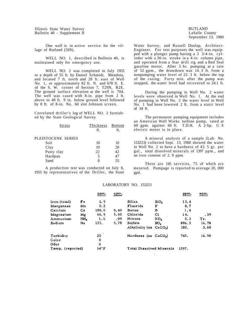
Illinois State Water Survey Bulletin 40 - Supplement II
One well is in active service for the vil-lage of Rutland (509).
WELL NO. 1, described in Bulletin 40, is maintained only for emergency use.
WELL NO. 2 was completed in July 1955 to a depth of 55 ft. by Daniel Schmidt, Mendota, and located 7 ft. north and 28 ft. east of Well No. 1, or approximately 82 ft. N. and 678 ft. E. of the S. W. corner of Section 7, T29N, R2E. The ground surface elevation at the well is 704. The well was cased with 8-in. pipe from 2 ft. above to 48 ft. 9 in. below ground level followed by 8 ft. of 8-in. No. 60 slot Johnson screen.
Correlated dri l ler ' s log of WELL NO. 2 furnish-ed by the State Geological Survey
Strata Thickness Bottom ft. ft.
PLEISTOCENE SERIES Soil 10 10 Clay 10 20 Putty clay 22 42 Hardpan 5 47 Sand 8 55
A production test was conducted on July 8, 1955 by representatives of the Driller, the State
RUTLAND LaSalle County September 13, 1960
Water Survey, and Russell Dunlap, Architect-Engineer. For test purposes the well was equip-ped with a plunger pump having a 3 3/4-in. cyl-inder with a 30-in. stroke in a 4-in. column pipe, and operated from a Star drill rig and a Red Seal gasoline motor. After 5 hr. pumping at a rate of 52 gpm., the drawdown was 14. 3 ft. from a nonpumping water level of 22. 3 ft. below the top of the casing. Forty min. after the pump was stopped, the water level had recovered to 24.1 ft.
During the pumping in Well No. 2 water levels were observed in Well No. 1. At the end of pumping in Well No. 2 the water level in Well No. 1 had been lowered 2 ft. from a static level of 34 ft.
The permanent pumping equipment includes an American Well Works turbine pump, rated at 60 gpm. against 60 ft. T.D.H. A 2-hp. U S electric motor is in place.
A mineral analysis of a sample (Lab. No. 153213) collected Sept. 13, 1960 showed the water in Well No. 2 to have a hardness of 43. 5 gr. per gal . , total dissolved minerals of 1397 ppm., and an iron content of 2. 9 ppm.
There are 145 services, 75 of which are metered. Pumpage is reported to average 20, 000 gpd.
LABORATORY NO. 153213

Illinois State Water Survey Bulletin 40 - Supplement II
Four wells are in service for the city of St. Charles (9269).
WELLS NO. 1 and 2 were described in Bul-letin 40 and reported as being abandoned.
WELL NO. 3 is described in Bulletin 40. The pump failed in May 1950 and after repairs were made, the air line was reinstalledandmeas-ured 240 ft. in length. The well was returned to service. In Sept. and Oct. 1952 the static water level measured 148 ft. below the pump base(elev. 690). In Nov. 1952 the air line was found inoper-ative.
In Dec. 1953 the rehabilitation of Well No.' 3 was started by J. P. Miller Artesian Well Co., Brookfield. The old casing and the liner were removed and the hole reamed out to 19 in. in diameter from the surface to 665 ft.; 17 in. in diameter from 665 to 710 ft., and 10 in. in diam-eter to the bottom at 2197 ft. By Apr. 1955 the well had been recased with 16-in. pipe, cemented in, from the surface to 690 ft. A 12-in. liner was set between 823 and 935 ft. depths.
On Apr. 21, 1955 the static water level was 167 ft. below the surface.
On May 4, 1955 a production test was con-ducted by the Contractor. For test purposes the well was equipped with 330 ft. of 10-in. column pipe; 7-stage Peerless turbine test pump; 10 ft. of suction pipe; 100-hp, electric motor. After 24 hr. continuous pumping at a rate of 1065 gpm., the drawdown was 143 ft. from a nonpumping water level of 177 ft. below the pump base.
A partial chemical analysis of a sample (Lab. No. 137602) collected May 4, 1955, after 24 hr. pumping at 1065 gpm., showed the water in Well No. 3 to have a hardness of 20.9 gr. per gal., total dissolved minerals of 689 ppm., and an iron content of 0.4 ppm.
WELL NO. 4 is described in Bulletin 40. In Dec. 1950 C. W. Varner removed the pump to rework the well and repair the pump. By Mar. 1951 the well had been shot at three depths: 400 lb. at 2130 ft., 700 lb. at 2070 ft., and 350 1b. at 2020 ft. Very little sand was bailed out so additional charges were set off as follows: 400 lb. at 2130 ft., 400 lb. at 2020 ft., 400 lb. at 1940 ft., and 350 lb. at 1380 ft.
ST. CHARLES Kane County November 3, 1958
In Mar. 1952 the production fell off. The depth of the well was measured and found to be 1833 ft. or 367 ft. above the original depth of 2200 ft. The static water level at the time was 151 ft. below the surface. In May 1952 the well had been cleaned out a second time to a depth of 2190 ft. The static water level at the time was 145 ft. below the pump base (elev. 691. 6). New pump bowls and shaft were installed and the pump bearings were replaced. In a production test conducted on May 31, 1952, during pumping at a maximum rate of 1146 gpm., the drawdown was 95 ft. from a static water level of 145 ft. below the pump base.
WELL NO. 5 is described in Bulletin 40. On May 20, 1950 this well had not yet been con-nected to the system. In a production test, much sand was pumped for the first 30 hr. During the last 9 hr. there was very little sand pumped. During pumping at 1200 gpm., the drawdown was 30 ft. from a static water level of 250 ft. below the pump base (elev. 760).
In Nov. 1952 the static water level was re-portedly 240 ft. below the pump base.
WELL NO. 6 was completed to a depth of 2250 ft. in Oct. 1955 by L. Cliff Neely, Batavia, and located on the same lot as Well No. 5, or approximately 1900 ft. S. and 1400 ft. E. of the N. W. corner of Section 34, T40N, R8E. The elevation of the top of the pump base is 766.1. The well was cased with 26-in. pipe from the surface to 79 ft. with 20-in. pipe from the sur-face to 334 ft., and with a 16-in. liner from 1021 to 1172. 7 ft., below which the hole was finished 15 1/4 in. in diameter. The 20-in. casing was pressure grouted. The well was shot with 800 qt. of liquid nitro at a depth of 1925 ft. The static water level was 243 ft. below the surface.
A production test was conducted on Oct. 17, 1955 by representatives of the Driller, the State Water Survey, and Caldwell-Rhoads, Consulting Engineers. After 11 hr. pumping at a rate of 1300 gpm., the drawdown was 118 ft. from a static wa-ter level of 240 ft. below the pump base. Thirty min. after pumping was stopped, the water level had recovered to 270 ft.
The permanent pump assembly consists of 400 ft. of 8-in. column pipe; 11-in., 7-stage Byron Jackson submersible pump, No. 328548,

2 - St. Charles
rated at 1000 gpm. at 410 ft. T.D.H.; 400 ft. of air line; 150-hp. electric motor.
A mineral analysis of a sample (Lab. No. 146378) collected in June 1958, after 1 hr. pumping at a rate of 1000 gpm., showed the wa-
ter in Well No. 6 to have a hardness of 12. 5 gr. per gal . , total dissolved minerals of 302 ppm., and an iron content of 0. 4 ppm.
Pumpage in July 1958 was reported to av-erage 1. 2 mgd.
LABORATORY NO. 146378
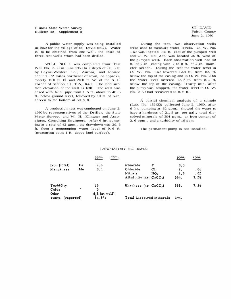
Illinois State Water Survey Bulletin 40 - Supplement II
A public water supply was being installed in 1960 for the village of St. David (862). Water is to be obtained from one well, the third of three test wells which had been drilled.
WELL NO. 1 was completed from Test Well No. 3-60 in June 1960 to a depth of 50. 5 ft. by Layne-Western Co., Aurora, and located about 1 l/2 miles northeast of town, or approxi-mately 1100 ft. N. and 2100 ft. W. of the S. E. corner of Section 10, T6N, R4E. The land sur-face elevation at the well is 630. The well was cased with 6-in. pipe from 1. 5 ft. above to 40. 5 ft. below ground level, followed by 10 ft. of 5-in. screen to the bottom at 50. 5 ft.
A production test was conducted on June 2, 1960 by representatives of the Driller, the State Water Survey, and W. H. Klingner and Asso-ciates, Consulting Engineers. After 6 hr. pump-ing at a rate of 42 gpm., the drawdown was 29. 3 ft. from a nonpumping water level of 9. 6 ft. (measuring point 1 ft. above land surface).
ST. DAVID Fulton County June 2, 1960
During the test, two observation wells were used to measure water levels. O. W. No. 1-60 was located 165 ft. east of the pumped well and O. W. No. 2-60 was located 20 ft. west of the pumped well. Each observation well had 40 ft. of 2-in. casing with 7 to 8 ft. of 2-in. diam-eter screen. During the test the water level in O. W. No. 1-60 lowered 12.4 ft. from 8.9 ft. below the top of the casing and in O. W. No. 2-60 the water level lowered 17. 7 ft. from 8. 2 ft. below the top of the casing. Thirty min. after the pump was stopped, the water level in O. W. No. 2-60 had recovered to 8. 6 ft.
A partial chemical analysis of a sample (Lab. No. 152422) collected June 2, 1960, after 6 hr. pumping at 62 gpm., showed the water to have a hardness of 21. 5 gr. per gal., total dis-solved minerals of 394 ppm., an iron content of 2. 6 ppm., and a turbidity of 16 ppm.
The permanent pump is not installed.
LABORATORY NO. 152422

Illinois State Water Survey Bulletin 40 - Supplement II
Water for the public supply of the city of St. Francisville (1040) is obtained from three wells.
WELL NO. 1, described in Bulletin 40, was equipped in 1951 witha new pumping installa-tion consisting of a Fairbanks-Morse Pomona turbine pump, rated at 50 gpm. and connected to a 5-hp. Fairbanks-Morse electric motor. In Aug. 1952 the nonpumping water level was 35 ft. below the ground surface and during pumping at 50 gpm. the drawdown was 89 ft.
WELL NO. 2: No change since Bulletin 40.
WELL NO. 3 was completed in 1951 to a depth of 136 ft. by E. I. Potts & Son, St. Francis-ville, and located about 1/4 mile south of Well No. 1 (South Well), or approximately 2000 ft. N. and 900 ft. W. of the S. E. corner of Section 20, T2N, R11W. The ground surface elevation at the well is 400. The well was cased with 10-in. drive pipe to 35 ft.
ST. FRANCISVILLE Lawrence County April 29, 1959
A production test was conducted on Sept. 28, 1951 by representatives of Heldt-Monroe Co., the City, and the State Water Survey. After 1 1/4 hr. pumping at a rate of 50 gpm., the draw-down was 91 ft. from a nonpumping water level of 33 ft. below the top of the casing. Thirty min. after the pump was stopped, the water level had returned to 33. 5 ft.
The pumping equipment consists of a Fair-banks-Morse Pomona turbine pump, rated at 50 gpm., connected to a 5-hp. electric motor.
A mineral analysis of a sample (Lab. No. 149505) collected Apr. 29, 1959, while pumping at a rate of 40 gpm., showed the water in Well No. 3 to have a hardness of 16 gr. per gal., total dissolved minerals of 335 ppm., and an iron con-tent of 1.1 ppm.
Pumpage is estimated to average 40, 000 gpd.
LABORATORY NO. 149505

Illinois State Water Survey Bulletin 40 - Supplement II
A public water supply was installed in 1954 for the village of St. Marie (347). One well is in service.
WELL NO. 1 was completed in Sept. 1953 to a depth of 54 ft. by Sims Drilling Co., Cham-paign, and located north of the Embarrass River, about 1/4 mile north of the village, or approxi-mately 530 ft. N. and 80 ft. E. of the S. W. cor-ner of Section 19, T6N, R14W. The elevation of the ground surface at the well is 465. The well was cased with 8-in. pipe from 3. 3 ft. above to 44. 4 ft. below the surface followed by 10 ft. 10. 5 in. of 8-in. diameter screen having No. 8 slot openings. The bottom of the screen was seated in 2 ft. of shale.
The well site is subject to flooding from the river. A 36-in. casing was set with the top 20 ft. above and the bottom 3 ft. below the ground surface.
A production test was conducted on Sept. 30, 1953 by representatives of the Driller, the State Water Survey, and Village officials. For test purposes the well was equipped with a plunger
ST. MARIE Jasper County July 1, 1960
pump operated from a Bucyrus-Erie drill rig. An air line was installed for measuring water levels. After 6 hr. pumping at rates of 33.5 to 61 gpm., the drawdown was 15. 5 ft. from a non-pumping water level of 14. 3 ft. Eleven min. after the pump was stopped, the water level had re-covered to 14. 3 ft.
During the test water levels were noted in O. W. No. 1 located 500 ft. S. and 50 ft. W. of Well No. 1. During the pumping in Well No. 1, water levels in the O. W. No. 1 were lowered 0. 3 ft. from 16. 38 ft. below the surface.
A mineral analysis of a sample (Lab. No. 133026) collected Sept. 30, 1953, after 6 hr. pump-ing at a rate of 61 gpm., showed the water in Well No. 1 to have a hardness of 14.8 gr. per gal., total dissolved minerals of 295 ppm., an iron content of 8. 3 ppm., and a turbidity of 63 ppm.
The pumping equipment includes a Jacuzzi submersible pump, rated at 120 gpm.
There are 111 services. Pumpage is esti-mated to average 18,000 gpd.
LABORATORY NO. 133026

Illinois State Water Survey Bulletin 40 - Supplement II
Two wells are in service for the city of Sandwich (3842).
WELL NO. 1, described in Bulletin 40 as having been drilled in 1911 to a depth of 600 ft., is equipped with 100 ft. of 8-in. column pipe; 12-in., 5-stage Byron Jackson turbine pump, rated at 800 gpm. against 92 ft. T.D.H.; 100 ft. of air line; 40-hp. U Selectric motor. AJohnston right angle gear drive is installed with power from a Continental engine.
On May 14, 1959 the nonpumping water level was 18 ft. below the pump base (elev. 661) which is 6 ft. below L. S. D.
SANDWICH DeKalb County May 14, 1959
WELL NO. 2, described in Bulletin 40 as having been drilled in 1939 to a depth of 600 ft., is equipped with 110 ft. of 8-in. column pipe; 12-in., 2-stage Byron Jackson turbine pump, No. 358514, rated at 750 gpm. against 110 ft. T.D.H.; 110 ft. of air line; 30-hp. U S electric motor.
On May 14, 1959 the nonpumping water level was 26 ft. below the pump base (elev. 667) at L. S. D.
There are 1300 services, all metered. Pumpage is reportedly estimated to average 400, 000 gpd.

Illinois State Water Survey Bulletin 40 - Supplement II
A public water supply was installed in May 1957 for Sauk Village (4687) on Sauk Trail about 2 miles east of Chicago Heights. The system is owned and operated by the Indian Hill Utility Co.
WELL NO. 1 was drilled in 1957 to a depth of 470 ft. by Wehling Well Works, Beecher, and located 1400 ft. N. and 1950 ft. W. of the S. E. corner of Section 25, T35N, R14E. The ground elevation at the well is 650. The well was cas-ed with 8-in. pipe to limestone. A production test was conducted on May 1, 1957 using the fol-lowing pumping equipment: 100 ft. of 6-in. col-umn pipe; 7-stage Peerless turbine test pump. Power was furnished from a gear drive. The static water level was reportedly 32 ft. With no air line installed, the drawdown was not report-ed. The pumping rate was started at 550 gpm. and maintained at that rate for 4 hr. , then ac-celerated to 860 gpm.; and after 1 l/4 hr. pump-ing, the pumping rate was decreased to 705 gpm. and maintained at that rate for 1 l/4 hr.
Subsequently, the permanent pump was installed consisting of 100 ft. of column pipe; Peerless turbine pump, No. 124490, rated at 1000 gpm.; 100 ft. of air line; 40-hp. U S electric motor.
A mineral analysis of a sample (Lab. No. 146508) collected Apr. 27, 1958, after 5 min. pumping, showed the water in Well No. 1 to have a hardness of 21. 8 gr. per gal., total dissolved minerals of 554 ppm., and an iron content of 0. 4 ppm.
SAUK VILLAGE Cook County December 5, 1959
A production test was conducted by the Driller on Dec. 5, 1959 after Well No. 2 was tested. After 2 hr. pumping at pump capacity, the drawdown was 15 ft. from a nonpumping wa-ter level of 23 ft. (air line reading).
WELL NO. 2 was completed to a depth of 480 ft. in Dec. 1959 by Wehling Well Works and located about 1/4 mile northeast of Well No. 1, or approximately 2300 ft. N. and 235 ft. W. of the S. E. corner of Section 25. The ground sur-face elevation at the well is 635. The well was cased with 12-in. pipe to an unreported depth.
A production test was conducted by the Driller on Dec. 3-5, 1959. For test purposes the well was equipped with 250 ft. of column pipe; 11 5/8-in. Byron Jackson turbine pump (No. 1234560); 248 ft. of air line; LeRoi gas engine. After 24 hr. pumping at a rate of 1000 gpm., the drawdown was 11 ft. from a static water level of 27 ft. below the pump base.
A partial chemical analysis of a sample (Lab. No. 151228), collected 24 hr. after pump-ing began at a rate of 1000 gpm., showed the wa-ter in Well No. 2 to have a hardness of 23. 3 gr. per gal., total dissolved minerals of 522 ppm., and an iron content of 0. 5 ppm.
There are 1000 services all metered.
Pumpage for the village for Jan. -Mar. 1958 averaged 264, 000 gpd.
LABORATORY NO. 146508

Illinois State Water Survey Bulletin 40 - Supplement II
Two wells (No. 4 and 5) are in service for the city of Savanna (4950).
WELLS NO. 1 and 2, described in Bulletin 40, were abandoned and filled in about 1953.
WELL NO. 3, described in Bulletin 40, was in stand-by use in 1956. Since then it has not been in service and reportedly maybe abandoned.
WELL NO. 4, described in Bulletin 40, is in service.
WELL NO. 5 was completed to a depth of 1804 ft. in Apr. 1953 by Milaeger Well Drilling Co., Milwaukee, Wis., and located at the north end of Main St., about 1 block south of the Mississippi River bridge about 3/4 mile north-west of Well No. 4, or approximately 1678 ft. N. and 690 ft. W. of the S. E. corner of Section 4, T24N, R3E. The ground surface elevation at the well is 600.
The well was first drilled to a depth of 1504 ft. in Dec. 1952 and cased as shown in Table A. A 6-hr, production test was conducted on Dec. 10, 1952 by representatives of the Driller, the State Water Survey, City officials, and Beling Engineering Consultants. After 6 hr. pumping at a rate of 300 gpm., the drawdown was 63.5 ft. from a nonpumping water level of 3. 5 ft.
TABLE A
Hole Sizes
26-in. from surface to 155 ft. 25-in. from 155 to 555 ft. 19-in. from 555 to 893 ft. 15-in. from 893 to 1277 ft. 12-in. from 1277 to 1504 ft.
Casing Record
26-in. id. from surface to 155 ft. 20-in. id. from surface to 555 ft. 16-in. id. from 632 to 783 ft. (liner) 12-in. id. from 1096 to 1172 ft. (liner)
SAVANNA Carroll County April 30, 1953
Following the test the hole was drilled 12 in. in diameter to a depth of 1804 ft. and shot with 450 lb. of explosives at seven levels as shown in Table B.
TABLE B
A second production test was conducted on Apr. 29-30, 1953 by the same representatives. For the test the well was equipped with 200 ft. of column pipe; a turbine pump, with 7-ft. bowl section; air line 207 ft, long; electric mo-tor. After 24 hr. pumping at rates of 350 gpm. gradually increased to 900 gpm., the final draw-down was 191 ft. from a nonpumping water level of 5 ft. One and one-half hr. after the pump was stopped, the water level had recovered to 50 ft.
A mineral analysis of a sample (Lab. No. 131834) collected Apr. 30, 1953, after 23 hr. pumping at a rate of 850 gpm., showed the water in Well No. 5 to have a hardness of 15. 7 gr. per gal., total dissolved minerals of 286 ppm., and an iron content of 0. 6 ppm.
The pumping equipment includes 200 ft. of 8-in. column pipe; 10-in., 13-stage Fairbanks-Morse Pomona turbine pump (No. AN4107), 10 ft. 2 in. long and rated at 500 gpm. at 390 ft. T.D.
H.; 20 ft. of 8-in. suction pipe; air line; 60-hp. U S electric motor.
There are approximately 2000 services.
Pumpage for 1956 averaged 433, 000 gpd.

2 - Savanna
Sample study summary log of WELL NO. 5 furnished by the State Geological Survey

Savanna - 3
LABORATORY NO. 131834

Illinois State Water Survey Bulletin 40 - Supplement II
A public water supply was installed in 1958 for Sturm's Subdivision, now village of Schaum-burg (986), located about 2 miles south of Lake Zurich, and about 2 miles east of Barrington.
WELL NO. 1 was completed in Jan. 1958 to a depth of 295 ft. by Hoover Water Well Service, Zion, and located approximately 300 ft. S. and 2590 ft. W. of the N. E. corner of Section 33, T43N, R10E. The elevation of the ground surface at the well is 840. The well was cased with 8-in. pipe to limestone at 238 ft., below which the hole was finished 8 in. in diameter to the bottom.
SCHAUMBURG Cook and Lake Counties September 9, 1960
The pumping equipment consists of 126 ft. of 3-in. column pipe; 4-in. Fairbanks-Morse submersible pump, No. LCBC1002XB; 1-hp. elec-tric motor.
A mineral analysis of a sample (Lab. No. 146911) collected June 5, 1958 showed the water in the well to have a hardness of 26. 7 gr. per gal., total dissolved minerals of 877 ppm., and an iron content of 0. 5 ppm.
There were 18 services at the time of this report. Pumpage is estimated to average 6000 gpd.
LABORATORY NO. 146911

Illinois State Water Survey Bulletin 40 - Supplement II
A public water supply was installed in 1960 for the Scots Plains Subdivision. The system is owned and operated by the Westview Utilities Co.
WELL NO. 1 was completed in Sept. 1960 to a depth of 205 ft. by Layne-Wes tern Co., Aurora, and located about 2 1/2 miles northwest of Naper-ville, or approximately 2523 ft. S. and 1285 ft. W. of the N. E. corner of Section 9, T38N, R9E. The elevation of the ground surface at the well is 709. The well was cased with 18-in. pipe to limestone at 69. 5 ft. and with 12 3/4-in. pipe from the surface to 79. 5 ft. (cemented in), below which the hole was finished at 12 in. in diameter to the bottom at 205 ft.
A production test was conducted on Sept.
SCOTS PLAINS SUBDIVISION DuPage County September 29, 1960
28-29, 1960 by representatives of the Driller and the State Water Survey. After 23 hr. pump-ing at 600 gpm., the drawdown was 17 ft. from a nonpumping water level of 25 ft. below the top of the casing (2 ft. above ground level). For the test the pumping equipment consisted of 150 ft. of 8-in. column pipe; 12-in., 4-stage. Layne test turbine; 150 ft. of air line; Continental gas en-gine.
A partial chemical analysis of a sample (Lab. No. 153371) collected Sept. 29, 1960, after 23 hr. pumping at 600 gpm., showed the water to have a hardness of 17.4 gr. per gal., total dissolved minerals of 339 ppm., and an iron con-tent of 0. 5 ppm.
The permanent pump is not yet installed.
LABORATORY NO. 153371

Illinois State Water Survey Bulletin 40 - Supplement II
Three wells furnish the entire public sup-ply for the city of Shelbyville (4821).
A completely new well field has been lo-cated southwest of Shelbyville about 3 miles from the wells described in Bulletin 40, which have been retired.
WELL NO. 1 was completed in Sept. 1955 to a depth of 59 ft. 10 in. by Layne-Western Co., Kirkwood, Mo., and located 640 ft. S. and 2387 ft. W. of the N. E. corner of Section 26, T11N, R3E. The ground surface elevation at the well is 557. A 34-in. hole was drilled from the sur-face to 59 ft. 10 in. The well was then cased with 26-in. pipe from the surface to 15 ft. and with 12-in. pipe from the surface to 44 ft. 10 in. followed by 15 ft. of Layne stainless steel screen, 12 in. in diameter. The annulus between the screen and casing and the wall of the hole was packed with gravel.
A production test was conducted on Oct. 24, 1955 by representatives of the Driller, the State Water Survey, and the Engineering Service Corporation. For test purposes the well was equipped with a Fairbanks-Morse Pomona test turbine pump with 30 ft. of column pipe with power from a right angle gear head operated from a gasoline engine. After 6 1/2 hr. pump-ing at 328 gpm., the drawdown was 6. 5 ft. from a nonpumping water level of 22. 2 ft. below the top of the casing. Thirty min. after the pump was stopped, the water level had recovered to 22. 9 ft.
The permanent pumping equipment consists of 40 ft. of 6-in. column pipe; 5-stage Layne turbine pump, rated at 500 gpm.; 5 ft. of 6-in. suction pipe; 43 ft. 8 in. of l/4-in. air line; 20-hp. U S electric motor. Auxiliary power is available from a Johns ton right angle gear drive connected to a 4-cylinder Hercules gas engine.
A partial chemical analysis of a sample (Lab. No. 138899) collected Oct. 24, 1955, after 6 1/2 hr. pumping, showed the water in Well No. 1 to have a hardness of 23. 5 gr. per gal., total dissolved minerals of 476 ppm., and a trace of iron.
WELL NO. 2 was completed in Sept. 1955 to a depth of 57 ft. 10 in. by Layne-Western Co. and located about 300 ft. north of Well No. 1, or approximately 340 ft. S. and 2387 ft. W. of the
SHELBYVILLE Shelby County November 19, 1957
N. E. corner of Section 26. The hole was drilled 34 in. in diameter from the surface to the bot-tom, and cased with 26-in. pipe from the sur-face to 15 ft. A 12-in. casing was set from the surface to 42 ft. 10 in. followed by 15 ft. of 12-in. Layne stainless steel shutter screen. The annulus between the screen and 12-in. casing and the wall of the hole was packed with gravel.
Sample study summary log of WELL NO. 2 fur-nished by the State Geological Survey
A production test was conducted on Oct. 20, 1955 by representatives of the Driller, the State Water Survey, and the Consulting Engineer. After 12 hr. pumping at a rate of 545 gpm., the drawdown was 11. 2 ft. from a nonpumping water level of 18. 5 ft. below the surface. Thirty-six min. after the pump was stopped, the water level had recovered to 17.1 ft.
The permanent pumping equipment consists of 40 ft. of 6-in. column pipe; 5-stage Layne turbine pump, 3 ft. 8 in. long and rated at 500 gpm.; 43 ft. 8 in. of air line; 5 ft. of 6-in. suc-tion pipe; 20-hp. U S electric motor. Auxiliary power for pumping is provided by the installation

2 - Shelbyville
of a 4-cylinder Hercules gas engine connected to a right angle gear drive.
WELL NO. 3 (the first in order of drilling) was completed in May 1955 to a depth of 56 ft. 8 in. by Layne-Western Co. and located 600 ft. north of Well No. 1, or approximately 40 £t. S. and 2387 ft. W. of the N. E. corner of Section 26. The hole was drilled 38 in. in diameter from top to bottom and cased with 30-in. pipe to 13 ft. and 12-in. pipe to 39 ft. followed by 15 ft. of 12-in. Layne stainless steel shutter screen. The annulus between the screen and 12-in. cas-ing and the wall of the hole was gravel packed.
A production test was conducted on June 8, 1955 by representatives of the Driller, the State Water Survey, and the Consulting Engi-neer. After 24 hr. pumping at a rate of 500
gpm., the drawdown was 10. 3 ft. from a non-pumping water level of 15. 5 below the top of the casing.
A mineral analysis of a sample (Lab. No. 137848) collected June 10, 1955, after 24 hr. pumping, showed the water in Well No. 3 to have a hardness of 27. 8 gr. per gal . , total dis-solved minerals of 508 ppm., and an iron con-tent of 0.1 ppm.
The permanent pumping equipment consists of 40 £t. of 6-in. column pipe; 5-stage Layne tur-bine pump, 3 ft. 8 in. long; 44 ft. of air line; 5 ft. of 6-in. suction pipe; 20-hp. U S electric motor.
There are 1900 services, 100% metered, and 95% of the population is served. Pumpage is reported to average 500,000 gpd.
LABORATORY NO. 137848

Illinois State Water Survey Bulletin 40 - Supplement II
Two wells are in service for the public wa-ter supply of the village of Sidney (686).
WELL NO. 1, described in Bulletin 40, was equipped in 1956 with a new Deming pump, rated at 75 gpm., connected to a 1 l/2-hp. U S elec-tric motor.
The new pump was installed because the pumping rate with the old one had declined to 20 gpm.
WELL NO. 2 was completed to a depth of 58 ft. 9 in. in Nov. 1954 by Guy McElwee and Son, Sidney, and located at the site of Test Hole No. 54-7, or approximately 1090 ft. S. and 850 ft. W. of the N. E. corner of Section 16, T18N, R10E. The test hole was drilled in Oct. 1954 to a depth of 61.6 ft. by C. M. Hayes, Champaign. The elevation of the ground surface at the well is 665.
A 16-in. hole was drilled to a depth of 58 ft. 9 in. below ground level. A 16-in. outer casing was set from ground level to 48 ft. 9 in. and 48 ft. of 8-in. inner casing was set from 2. 5 ft. above ground level to 45. 5 ft. followed by 13 ft. of 8-in. screen with No. 50 slot openings. The annulus between the screen and the wall of the hole and between the two casings was packed with 1/4 to 3/8-in. Covington gravel.
A production test was conducted on Nov. 16, 1954 by representatives of the Driller, the State Water Survey, Village officials, and Wilson and Anderson, Consulting Engineers. For the test a Fairbanks-Morse turbine pump, belt driven from a Ford gas engine, was installed. An air
SIDNEY Champaign County April 29, 1960
line was installed but it was defective. Water levels were measured by dropline. After 5 hr. pumping at rates of 150 to 318 gpm., the draw-down was 13.1 ft. from a static water level of 25 ft. below the top of the casing. Fifteen min. aft-er the pump was stopped, the water level had re-covered to 31. 2 ft.
Correlated driller's log of TEST HOLE NO. 54-7 furnished by the State Geological Survey
The pumping equipment includes a Deming turbine pump, rated at 140 gpm., connected to a 3-hp. U S electric motor.
A mineral analysis of a sample (Lab. No. 152155) collected Apr. 26, 1960, after 45 min. pumping, showed the water in Well No. 2 to have a hardness of 12.8 gr. per gal., total dissolved minerals of 455 ppm., and an iron content of 7 ppm. The well had not been in use for several weeks.
From Apr. 1, 1959 to Mar. 31, 1960 pump-age averaged 56, 000 gpd.
LABORATORY NO. 152155

Illinois State Water Survey Bulletin 4.0 - Supplement II
One new well has been added to the public water supply of Silv.is (3973) since publication of Bulletin 40. The supply is now obtained from two drilled wells.
WELL NO. 1, the shallow dug well describ-ed in Bulletin 40, has been abandoned, filled in, and covered over.
WELL NO. 2, described in Bulletin 40, was repaired in May 1957 and equipped with a new pump assembly. In 1956 the 10-in. casing was extended to ground level. There was re-portedly 11 ft. of interference between Wells No. 1 and 2. The new pump installation includes 210 ft. of 6-in. id. column pipe; 9 l/2-.in., 10-stage Peerless turbine pump, rated at 400 gpm.; 30 ft. of 6-in. suction pipe; 210 ft. of l/4-in. air line; 30-hp. electric motor.
In 1956, after 5 hr. pumping at 400 gpm., the drawdown was 67 ft. from a nonpumping wa-ter level of 113 ft. below the discharge head.
WELL NO. 3 was completed to a depth of 1680 ft. in Apr. 1956 by Thorpe Well Drilling Co., DesMoines, Iowa, and located about 250 ft. north of Well No. 2, or approximately 1000 ft. S. and 1250 ft. E. of the N. W. corner of Section 32, T18N,. R1E. The elevation of the ground surface at the well is 580.
The hole and casing record is shown in Table A.
A production test was conducted on May 1, 1956 by representatives of the Drilling Contractor, the State Water Survey, and Missman, Stanley, Farmer & Associates, Consulting Engineers,
SILVIS Rock Island County May 7, 1959
Rock Island. After 7 1/2 hr. pumping at a rate of 483 gpm., the drawdown was 136 ft. from a nonpumping water level (Well No. 2 pumping simultaneously) of 122 ft. Five min. after pump-ing was stopped, the water level had recovered to 173 ft.
TABLE A
Hole Size
26-in. from 0 to 123 ft. 23-in. from 123 to 672 ft. 17 l/4-in. from 672 to 1680 ft.
Casing Size
24-in. from 0 to 119 l/2 ft. 18-in. from 0 to 672 ft. (cemented with 835 sacks of cement)
The permanent pumping equipment install-ed in 1956 consists of 300 ft. of 6-in. column pipe; 9 l/2-in., 10-stage Fairbanks-Morse sub-mersible turbine pump, No. PV4230, rated at 600 gpm.; 2 air lines, No. 1 is 203 ft. long and No. 2 is 300 ft. long; 60-hp. electric motor.
In Apr. 1957, after pumping for 5 hr. at a rate of 600 gpm., the drawdown was 177 ft. from a nonpumping water level of 118 ft.
A mineral analysis of a sample (Lab. No. 149561) collected May 5, 1959 showed the water in Well No. 3 to have a hardness of 20 gr. per gal., total dissolved minerals of 1456 ppm., and an iron content of 0. 4 ppm.
Pumpage for 1958 averaged 261, 370 gpd.
LABORATORY NO. 149561

2 - Silvis
Summary sample study log of WELL NO. 3 furnished by the State Geological Survey

Illinois State Water Survey Bulletin 40 - Supplement II
Two wells are in service for the public wa-ter supply of Silvis Heights Subdivision (est, 12Z5).
WELL NO. 1 was described in Supplement I of Bulletin 40.
WELL NO. 2 was completed to a depth of 556 ft. in Nov. 1957 by Carl Larson, Peerless Service Co., Orion, and located about 50 ft. east of Well No. 1, or approximately 40 ft. N. and 2040 ft. W. of the S. E. corner of Section 31, T18N, R1E. The ground surface elevation at the well is 690. The well was cased with 16-in. pipe from the surface to 79 ft. and with 10-in. pipe from the surface to 225 ft. An 8-in. liner was set from 380 to 440ft., below which the hole was finished 8 in. in diameter.
A production test was conducted on Jan. 24, 1958 by representatives of the Driller, the State
SILVIS HEIGHTS SUBDIVISION Rock Island County November 13, 1958
Water Survey, and Louis Pappmeier, Consulting Engineer. The permanent pump was installed consisting of a Deming vertical turbine connected to a 25-hp. electric motor. A 250-ft. air line was installed. After 3 hr. pumping at rates ac-celerated from 130 to 225 gpm., the final draw-down was 7. 5 ft. from a static water level of 168. 5 ft. One min. after pumping was stopped, the water level had recovered to 170 ft.
A mineral analysis of a sample (Lab. No. 145584) collected Jan. 24, 1958, after 2 1/2 hr. pumping at 225 gpm., showed the water in Well No. 2 to have a hardness of 14.2 gr. per gal., total dissolved minerals of 356 ppm., and an iron content of 0. 6 ppm.
There are approximately 350 services. Pumpage is estimated to average 60,000 gpd.
LABORATORY NO. 145584

2 - Silvis Heights Subdivision
Summary sample study log of WELL NO. 2 furnished by the State Geological Survey

Illinois State Water Survey Bulletin 40 - Supplement II
Two wells are in service for the village of Somonauk (899).
WELL NO. 1 (East Well), described in Bul-letin 40 as having been drilled to a depth of 190 ft. in 1880, is equipped with 70 ft. of 5-in. col-umn pipe; 8-in., 9-stage Byron Jackson sub-mersible pump, No. 341954, rated at 300 gpm. against 150 ft. T.D.H.; 70 ft. of air line; 20-hp. electric motor.
On May 14, 1959 the nonpumping water level was 15 ft. below the pump base (elev. 685) which is 5 ft. below L. S. D.
SOMONAUK DeKalb County May 14, 1959
WELL NO. 2 (West Well), described in Bul-letin 40 as having been drilled to a depth of 502 ft. in 1903, is equipped with 70 ft. of 5-in. col-umn pipe; 8-in., 9-stage Byron Jackson sub-mersible pump, No. 341955, rated at 300 gpm. against 150 ft. T.D.H.; 70 ft. of air line; 20-hp. electric motor.
On May 14, 1959 the nonpumping water level was 13 ft. below the pump base (elev. 685) which is 5 ft. below L. S. D.
There are 290 services, 16 of which are metered and none is read. Pumpage is esti-mated to average 50,000 gpd.

Illinois State Water Survey Bulletin 40 - Supplement II
The village of South Chicago Heights (4043) obtains its water supply from two wells.
WELL NO. 1 is described in Bulletin 40.
WELL NO. 2 was completed in Mar. 1956 to a depth of 250 ft. by Wehling Well Works, Beecher, and located at the rear of the village hall, about 40 ft. from Well No. 1, or approxi-mately 1650 ft. N. and 118 ft. W. of the S. E. corner of Section 29, T35N, R14E. The ground surface elevation at the well is 715.
The well was cased with 63 ft. of genuine wi. pipe, below which the hole was finished at 11 1/2 in. in diameter to the bottom at 250 ft. The Drilling Contractor reported a production test was conducted on May 26, 1956. After 3 hr. pumping at a rate of 500 gpm., the drawdown was 66 ft. from a nonpumping water level of 82 ft. below the top of the casing (24 in. above ground level).
The permanent pumping equipment con-sists of a Peerless turbine pump, No. 120550,
SOUTH CHICAGO HEIGHTS Cook County April 29, 1958
rated at 450 gpm. powered by a 50-hp. electric motor.
A mineral analysis of a sample (Lab. No. 146509) collected Apr. 29, 1958 showed the wa-ter in Well No. 2 to have a hardness of 25. 9 gr. per gal . , total dissolved minerals of 503 ppm., and an iron content of 0. 4 ppm.
From Apr. 11, 1957 to Mar. 7, 1958 pump-age averaged 270,000 gpd.
Correlated dri l ler 's log of WELL NO. 2 fur-nished by the State Geological Survey
Strata Thickness Bottom ft. ft.
PLEISTOCENE SERIES Cinders and fill 3 3 Clay and very little
gravel 53 56 Soft broken rock 7 63
SILURIAN SYSTEM Limestone 187 250
LABORATORY NO. 146509

Illinois State Water Survey Bulletin 40 - Supplement II
Two wells are in service for the village of South Elgin (2624).
WELL NO. 1, described in Bulletin 40, was deepened in 1952 to a depth of 1400 ft. New pump-ing equipment was installed consisting of 340 ft. of 5-in. column pipe; 8-in., 11-stage Aurora tur-bine pump, No. 66519, rated at 150 gpm. against 300 ft. T.D.H.; 340 ft. of air line; 20-hp. U S electric motor.
On Feb. 20, 1959 water was pumped at a rate of 175 gpm. for a 20 min. period. The draw-down was 30 ft. from a nonpumping water level of 260 ft. below the pump base (elev. 761. 2).
WELL NO. 2 was completed in 1951 to a depth of 133 ft. by Ed O'Brien, Elgin, and located in the Crystal Springs Subdivision in the southeast part of town near the intersection of Spring and Fulton St., or approximately 500 ft. N. and 1400 ft. W. of the S. E. corner of Section 35, T41N, R3E. The ground surface elevation at the well is 730. The well was cased with 111 ft. of 12-in. pipe followed by 10 ft. of No. 12 Cater shutter screen.
SOUTH ELGIN Kane County June 16, 1959
A production test was conducted on Apr. 15, 1952 by representatives of the Driller, the State Water Survey, and City Engineer, Victor Kasser. After 2 hr. pumping at a rate of 271 gpm., the drawdown was 33 ft. 2 in. from a static water lev-el of 29 ft. 9 in. below the top of the casing (1 ft. above ground level). Thirty min. after the pump was stopped, the water level had recovered to 31. 5 ft. For the test a vertical turbine pump was set at 80 ft.
The permanent pumpassembly, installed in 1952, consists of 90 ft. of 5-in. column pipe; 8-in., 11-stage Aurora turbine pump, No. 60909, rated at 200 gpm. at 260 ft. T.D.H.; 90 ft. of air line; 20-hp. U S electric motor.
A partial chemical analysis of a sample (Lab. No. 149964) collected June 16, 1959 showed the water in Well No. 2 to have a hardness of 26.7 gr. per gal., total dissolved minerals of 538 ppm., and an iron content of 1.1 ppm.
Meters were not being read in 1958.
Pumpage was estimated to average 100,000 gpd.
LABORATORY NO. 149964

Illinois State Water Survey Bulletin 40 - Supplement II
A public water supply was installed for the Southlands Subdivision (est. 250) in 1954. The subdivision is located about 1/2 mile west of Tinley Park and the water system is owned and operated by Midwest-Tinley Water Co.
WELL NO. 1 was completed in Oct. 1954 to a depth of 459 ft. by J. P. Miller Artesian Well Co., Brookfield, and located on 173rd St. and Overhill Ave., or approximately 1325 ft. N. and 2400 ft. E. of the S. W. corner of Section 25, T36N, R12E. The ground surface elevation at the well is 705. The well was cased with 10-in. gwi. pipe from 12 in. above the pump station floor to 98 ft. below the ground level. The hole was finished 10 in. in diameter to the bottom of the hole at 459 ft. total depth.
A production test was conducted by the
SOUTHLANDS SUBDIVISION Cook County January 10, 1958
Driller on Oct. 28, 1954 using test pumping e-quipment. After 8 l/2 hr. pumping at a rate of 265 gpm., the drawdown was 66 ft. from a non-pumping water level of 28 ft. below the top of the casing (about 2 ft. above the ground level). Analysis of a sample (Lab. No. 136174) collected Oct. 28, 1954, after 8 l/2 hr. pumping, showed the water to have a hardness of 42.4 gr. per gal., total dissolved minerals of 824 ppm., and an iron content of 1. 4 ppm.
Subsequently, the permanent pump assem-bly was installed and consists of 100 ft. of col-umn pipe; 8-stage Peerless turbine pump rated at 130 gpm. at 168 ft. T.D.H.; 100 ft. of air line; 10 ft. of suction pipe; 7 l/2-hp. U S electric mo-tor.
Pumpage for 1957 averaged 4700 gpd.
LABORATORY NO. 136174

Illinois State Water Survey Bulletin 40 - Supplement II
One well is in service for the public water supply of the village of South Wilmington (730). Another well is maintained for emergency use, and a third one has been abandoned.
WELL NO. 1, described in Bulletin 40, has been cross connected to the system, accord-ing to a State Department of Public Health report of Mar. 15, 1955. The water is discharged to the fire reservoir without treatment, and can be used only for fire protection.
WELL NO. 2, the shallow drilled well de-scribed in Bulletin 40, has been sealed andaban-doned.
WELL NO. 3 was completed to a depth of 993. 5 ft. in May 1950 by Joliet Pump Co., Joliet, and located at the rear of the village hall near Fourth St., or approximately 820 ft. N. and 1294 ft. E. of the S. W. corner of Section 11, T31N, R8E. The elevation of the ground surface at the well is 600. The well was cased with 10-in. pipe from the ground surface to 77 ft. 6 in., and with 8-in. pipe from the ground surface to a depth of 294 ft.
A production test was conducted on May 31, 1950 by representatives of the Driller and the State Water Survey. For test purposes a work-ing barrel, operated by the engine for the drill rig, was installed with the cylinder set on 4-in. discharge column at a depth of 255 ft. 6 in. Aft-er 8 hr. pumping at 40 gpm., the drawdown was 121 ft. from a nonpumping water level of 112 ft.
SOUTH WILMINGTON Grundy County October 30, 1958
A mineral analysis of a sample (Lab. No. 121959) collected June 15, 1950, after 8 hr. pump-ing at 40 gpm., showed the water in Well No. 3 to have a hardness of 21.8 gr. per gal., total dissolved minerals of 1304 ppm., and an iron content of 0. 4 ppm.
On July 7, 1950 the permanent pump was installed consisting of 300 ft. of 5-in. column pipe; 9-stage Berkeley turbine pump, No. 3540-F, 10 ft. in length and rated at 45 gpm.; 10 ft. of suction pipe; 15-hp. electric motor. A 5-hp. Berkeley centrifugal booster pump, rated at 150 gpm. was also installed. In Mar. 1952 the pump was out of the well for repairs for several months. The pump shaft was broken and other sections showed considerable corrosion. After numerous breakdowns in the pump, during which Well No. 1 was put into emergency service, a new Reda submersible pump was installed about Feb. 1, 1955. The pump is rated at 30 gpm. and operated by an electric motor.
In June 1956 a new 25,000 gal. elevated steel storage tank was erected.
A partial chemical analysis of a sample (Lab. No. 137231) collected Mar. 17, 1955 showed the water in Well No. 3 to have a hardness of 19.8 gr. per gal., total dissolved minerals of 1284 ppm., and an iron content of 0.1 ppm.
There are approximately 150 services, and pumpage for Oct. 1958 averaged 20, 000 gpd.
LABORATORY NO. 121959

2 - South Wilmington
Sample study summary log of WELL NO. 3 furnished by the State Geological Survey

Illinois State Water Survey Bulletin 40 - Supplement II
Three wells are in service for Starved Rock State Park. There are four other wells of minor importance but incidental to the Park water supply.
WELLS NO. 1 (Park Swimming Pool) and 2 (Park Garage) are described in Bulletin 40.
WELL NO. 3 was completed in Sept. 1953 to a depth of 401 ft. by Varner Well Drilling Co., Dubuque, Iowa, and located about 250 ft. west of Well No. 2 (Park Garage Well), or approximately 1250 ft. S. and 700 ft. W. of the N. E. corner of Section 21, T33N, R2E. The ground surface elevation at the well is 460. The well was cased with 12-in. od. pipe from the surface to 205 ft., below which the hole was finished 12 in. in di-ameter.
A production test was conducted on Sept. 18-19, 1953 by representatives of the Driller, the State Water Survey, and the State Division of Architecture and Engineering. After 8 hr. pumping at 355 gpm., the drawdown was 43 ft. from a nonpumping water level of 47. 5 ft. below
STARVED ROCK STATE PARK LaSalle County September 13, 1960
the top of the casing.
During the test, water levels were observ-ed in Well No. 2. The water in Well No. 2 low-ered 18 ft. from a starting level of 37 ft.
The Well No. 3 is equipped with a Fair-banks-Morse turbine pump connected to a 40-hp. U S electric motor.
A mineral analysis of a sample (Lab. No. 153217) collected Sept. 13, 1960 showed the water in Well No. 3 to have a hardness of 21.2 gr. per gal., total dissolved minerals of 424 ppm., and an iron content of 2. 4 ppm.
Well No. 3 is used as the main source of the Park's water supply.
The old C. C. Camp Wells No. 1 and 2, the old Salt Weil, and the old Sulphur Well are avail-able for limited use although only incidental to the Park's main water supply.
The daily pumpage is reported to average 20,000 gpd.
LABORATORY NO. 153217

Illinois State Water Survey Bulletin 40 - Supplement II
Two wells furnish water to the public sup-ply of Stillman Valley (598).
WELL NO. 1, described in Bulletin 40, was completely rehabilitated and the pump repaired in 1957 or 1958. The well now is maintained for emergency service.
WELL NO. 2 was completed in Sept. 1954 to a depth of 445 ft. by Allabaugh Well Co., Rock-ford, and located adjacent to the elevated tank, or approximately 300 ft. N. and 750 ft. E. of the S. W. corner of Section 1, T24N, R11E. The ground elevation at the well is 740. The well was cased with 159 ft. 6 in. of 12-in. pipe and with 8-in. pipe from the surface to 179 ft. 6 in., below which the hole was finished 8 in. in diameter to the bottom. The annulus between the two cas-ings and between the 8-in. casing and the wall of the 12-in. hole was pressure grouted.
During the drilling of the well, water levels were observed as shown in Table A.
The pumping equipment includes a Fair-
STILLMAN VALLEY Ogle County October 10, 1960
banks-Morse Pomona turbine pump, No. 175987, rated at 280 gpm. and connected to a 25-hp. e-lectric motor.
A mineral analysis of a sample (Lab. No. 153360) collected Oct. 6, 1960 showed the water in Well No. 2 to have a hardness of 16. 5 gr. per gal., total dissolved minerals of 294 ppm., and an iron content of 0. 9 ppm.
There are 150 services. Pumpage is re-ported to average 40,000 gpd.
TABLE A
LABORATORY NO. 153360
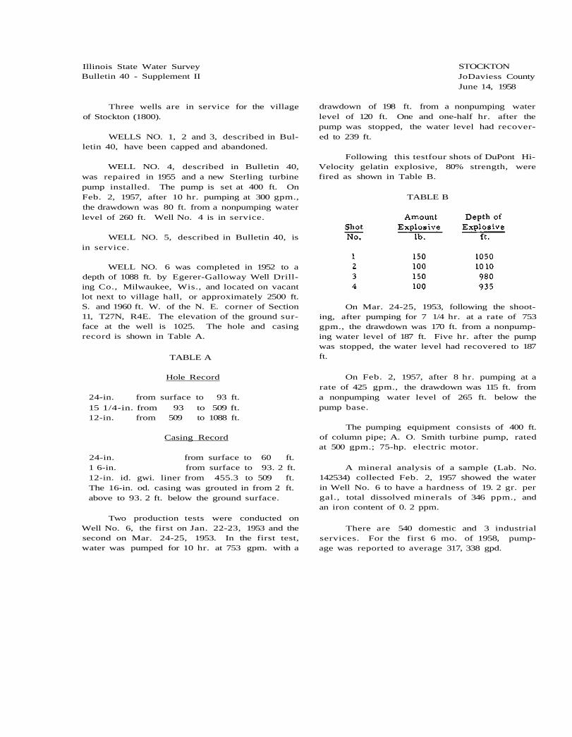
Illinois State Water Survey Bulletin 40 - Supplement II
Three wells are in service for the village of Stockton (1800).
WELLS NO. 1, 2 and 3, described in Bul-letin 40, have been capped and abandoned.
WELL NO. 4, described in Bulletin 40, was repaired in 1955 and a new Sterling turbine pump installed. The pump is set at 400 ft. On Feb. 2, 1957, after 10 hr. pumping at 300 gpm., the drawdown was 80 ft. from a nonpumping water level of 260 ft. Well No. 4 is in service.
WELL NO. 5, described in Bulletin 40, is in service.
WELL NO. 6 was completed in 1952 to a depth of 1088 ft. by Egerer-Galloway Well Drill-ing Co., Milwaukee, Wis., and located on vacant lot next to village hall, or approximately 2500 ft. S. and 1960 ft. W. of the N. E. corner of Section 11, T27N, R4E. The elevation of the ground sur-face at the well is 1025. The hole and casing record is shown in Table A.
TABLE A
Hole Record
24-in. from surface to 93 ft. 15 1/4-in. from 93 to 509 ft. 12-in. from 509 to 1088 ft.
Casing Record
24-in. from surface to 60 ft. 1 6-in. from surface to 93. 2 ft. 12-in. id. gwi. liner from 455.3 to 509 ft. The 16-in. od. casing was grouted in from 2 ft. above to 93. 2 ft. below the ground surface.
Two production tests were conducted on Well No. 6, the first on Jan. 22-23, 1953 and the second on Mar. 24-25, 1953. In the first test, water was pumped for 10 hr. at 753 gpm. with a
STOCKTON JoDaviess County June 14, 1958
drawdown of 198 ft. from a nonpumping water level of 120 ft. One and one-half hr. after the pump was stopped, the water level had recover-ed to 239 ft.
Following this testfour shots of DuPont Hi-Velocity gelatin explosive, 80% strength, were fired as shown in Table B.
TABLE B
On Mar. 24-25, 1953, following the shoot-ing, after pumping for 7 1/4 hr. at a rate of 753 gpm., the drawdown was 170 ft. from a nonpump-ing water level of 187 ft. Five hr. after the pump was stopped, the water level had recovered to 187 ft.
On Feb. 2, 1957, after 8 hr. pumping at a rate of 425 gpm., the drawdown was 115 ft. from a nonpumping water level of 265 ft. below the pump base.
The pumping equipment consists of 400 ft. of column pipe; A. O. Smith turbine pump, rated at 500 gpm.; 75-hp. electric motor.
A mineral analysis of a sample (Lab. No. 142534) collected Feb. 2, 1957 showed the water in Well No. 6 to have a hardness of 19. 2 gr. per gal., total dissolved minerals of 346 ppm., and an iron content of 0. 2 ppm.
There are 540 domestic and 3 industrial services. For the first 6 mo. of 1958, pump-age was reported to average 317, 338 gpd.

2 - Stockton
LABORATORY NO. 142534

Illinois State Water Survey Bulletin 40 - Supplement II
A public water supply is being installed for the village of Stonefort (349).
Village WELL NO. 1, originally American Legion Post Well No. 1, was completed about 1950 or 1951 to a depth of 90 ft. by Quentin Richey, Carrier Mills, and located 1100 ft. N. and 2000 ft. E. of the S. W. corner of Section 30, T10S, R5E. The ground surface elevation at the well is 400. The well was cased with 7-in. pipe to 41 ft. 6 in.
A production test was conducted on Aug. 18, 1958 by representatives of the Driller, the State Water Survey, and Robert R. Callaghan, Inc., Consulting Engineers. For the test the well was equipped with the American Legion Post pump installation of a Rex centrifugal suction pump, rated at 15, 000 gal. per hr. connected to a Wis-consin gas engine with 3-in. piston and 3 l/4-in. stroke. After 9 hr. of interrupted pumping the final rate of pumping was 70 gpm. and the draw-down was 21 ft. from a nonpumping water level of 0. 7 ft. below the top of the casing. Fifteen min.
STONEFORT Saline and Williamson Counties July 18, 1960
after the pump was stopped, the water level had recovered to 11.1 ft.
During the production test in Well No. 1, water levels were observed in American Legion Post Well No. 2, 500 ft. to the southwest of Well No. 1. After 6 3/4 hr. pumping in Well No. 1, the water level in Well No. 2 was lowered 8. 3 ft. from a static level of 3. 1 ft. below the top of the casing.
The permanent pump in Well No. 1, in-stalled recently by Lane Machinery Co., consists of 50 ft. of 2 l/2-in. column pipe; 12-stage John-ston turbine pump, rated at 50 gpm. at 250 ft. T.D.H.; 2 l/2-in. suction strainer; 5-hp. electric motor.
A mineral analysis of a sample (Lab. No. 152355) collected June 1, 1960 showed this water to have a hardness of 11 gr. per gal., total dis-solved minerals of 669 ppm., and an iron con-tent of 1. 2 ppm.
LABORATORY NO. 152355

Illinois State Water Survey Bulletin 40 - Supplement II
A public water supply was installed in 1957 for the village of Streamwood (4821) originally called Streamwood Development Corporation, located about 1 mile north of Bartlett. The wa-ter system is owned and operated by Streamwood Utilities Corporation.
Three test wells were drilled in 1956 by J. P. Miller Artesian Well Co., Brookfield.
TEST WELL NO. 1 was drilled to a depth of 108 ft. and located 65 ft. S. and 2045 ft. E. of the N. W. corner of Section 23, T41N, R9E. The well penetrated sand and gravel from 100 to 106 ft. and was cased with 6-in. pipe to a depth of 97 ft. 8 in. followed by 10 ft. of Houston screen. The Driller reported that after 3 hr. pumping at a rate of 50 gpm., the drawdown was 2 ft. from a static water level of 61 ft. below the surface (elev. 827).
The well was subsequently capped below the ground surface.
TEST WELL NO. 2 was drilled to a depth of 134 ft. and located 635 ft. S. and 1135 ft. E. of the N. W. corner of Section 23. The well penetrated sand and gravel from 115 to 135 ft. and was cased with 6-in. pipe from the surface to 117 ft. followed by 10 ft. of Houston screen. The Driller reported that after 3 l/2 hr. pump-ing at a rate of 50 gpm., the drawdown was 3 ft. below a static water level of 52 ft. below the surface (elev. 817).
The well was subsequently capped.
TEST WELL NO. 3 was drilled to a depth of 76 ft. in Nov. 1956 and located 1460 ft. S. and 1000 ft. E. of the N. W. corner of Section 23. The well penetrated sand and gravel from 60 to 75 ft. and was cased with 5-in. pipe to 66 ft. 5 in. followed by 10 ft. of Houston screen. The Driller reported that after 3 hr. pumping at a rate of 30 gpm., the drawdown was 1 ft. from a static level of 65 ft. below the surface (elev. 825).
WELL NO. 1, Source Well, was completed in Aug. 1957 to a depth of 120 ft. by J. P. Miller Artesian Well Co. and located at McCabe Drive and Grow Lane, or approximately 760 ft. S. and 2156 ft. E. of the N. W. corner of Section 23. The ground surface elevation at the well is 830. The Driller reported encountering a gravel for-mation from 95 ft. to bedrock at 132 ft. The well was cased with 10-in. pipe from 30 in. above
STREAMWOOD Cook County July 14, 1958
to 110 ft. below the ground surface followed by 10 ft. of 10-in. brass screen to the bottom at 120 ft. The bore hole was finished 15 in. in di-ameter from the surface to 120 ft., and the an-nular space outside the casing and screen was backfilled from 120 to 100 ft. with silica gravel and from 100 ft. to the surface with an imper-vious material.
The Well Contractor reportedly conducted a production test on Aug. 7, 1957 using pumping test equipment. After 7 1/2 hr. pumping at a rate of 1300 gpm., the drawdown was 10 ft. from a nonpumping water level of 60 ft. below the top of the casing.
Subsequently, the permanent pump assem-bly was installed and consists of 80 ft. of 6-in. column pipe; 5-stage Peerless turbine pump, No. 125835, rated at 315 gpm. at 212 ft. T.D.H.; 80 ft. of air line; 25-hp. U S electric motor.
A mineral analysis of a sample (Lab. No. 147272) collected July 14, 1958 showed the water to have a hardness of 28.5 gr. per gal., total dissolved minerals of 583 ppm., and an iron content of 2. 9 ppm.
WELL NO. 2 was completed in Aug. 1957 to a depth of 121 ft. by J. P. Miller Artesian Well Co. and located about 16 ft. west of Well No. 1. The well was cased with 16-in. pipe from 12 in. above to 91 ft. below the ground level, followed by 30 ft. of 16-in. stainless steel screen to the bottom at 121 ft. The hole was finished 36 in. in diameter to the bottom at 121 ft. The annular space outside the screen and casing was back-filled from 121 to 80 ft. with silica gravel and from 80 ft. to the surface with an impervious material. Upon completion of the well, the Con-tractor reportedly pumped 9 hr. at a rate of 1300 gpm. with a drawdown of 10 ft. from a non-pumping water level of 60 ft. below the top of the casing.
Correlated driller's log of WELL NO. 2 furnish-ed by the State Geological Survey
Strata Thickness Bottom ft. ft.
PLEISTOCENE SERIES Clay 95 95 Gravel 26 121
In July 1958 there were 300 services and 5000 are planned. Pumpage is estimated to average 50, 000 gpd.

2 - Streamwood
LABORATORY NO. 147272

Illinois State Water Survey Bulletin 40 - Supplement II
Two wells are in service for the village of Sugar Grove (326).
WELL NO. 1, described in Bulletin 40, is not in service.
WELL NO. 2, described in Bulletin 40, is in service.
WELL NO. 3 was completed to a depth of 104 ft. in 1948 by Hayes and Sims, Champaign, and located approximately 2400 ft. S. and 2500 ft. W. of the N. E. corner of Section 21, T38N, R7E. Land surface elevation at the well is 727. The permanent well was drilled about 12 ft. north of a test well which had been drilled to the same depth penetrating a sand and gravel formation. Well No. 1 was cased with 10-in. pipe from the surface to 41 ft. 7 in. and with 8-in. pipe from the surface to 91 ft. 8 in., below which was 12 ft. of exposed length of 8-in. Johnson Everdur telescope screen having No. 30 slot openings.
A production test was conducted on Apr. 28, 1948 by representatives of the Driller, the State Water Survey, and the Village officials. After 4 1/2 hr. pumping at a rate of 106 gpm., the
SUGAR GROVE Kane County June 23, 1960
drawdown was 5. 8 ft. from a nonpumping water level of 49.6 ft. below the top of the 10-in. cas-ing. Five min. after the pump was stopped, the water level had recovered to 49. 6 ft.
On Mar. 9, 1960, when pumping at 100 gpm. for 5 min., the drawdown was 30 ft. from a non-pumping water level of 40 ft.
A chemical analysis of a sample (Lab. No. 151911) collected Mar. 9, 1960 showed the water to have a hardness of 25.2 gr. per gal., total dis-solved minerals of 503 ppm., and an iron con-tent of 0. 2 ppm.
The pumping equipment consists of 70 ft. of 6-in. column pipe; 8-in., 6-stage Aurora tur-bine pump, No. 80952, rated at 100 gpm. against 180 ft. T.D.H.; 70 ft. of air line; 10-hp. U S electric motor.
In June 1960 this pump was reportedly hav-ing trouble from sand clogging and was producing about 30 gpm.
There are 95 services, all metered. Pump-age is estimated to average 18, 000 gpd.
LABORATORY NO. 151911

Illinois State Water Survey Bulletin 40 - Supplement II
A public water supply was installed in 1956 for Suncrest Highlands (est. 300), a subdivision located south of Bloomingdale.
WELL NO. 1 was completed in 1956 to a depth of 1395 ft. by Milaeger Well Drilling Co., Milwaukee, Wis., and located 2150 ft. N. and 600 ft. E. of the S. W. corner of Section 14, T40N, R10E. The elevation of the ground surface at the well is 790. The well was cased with 20-in. steel pipe from the surface to 104 ft. and with 16-in. steel pipe from the surface to 425 ft. The annulus outside the 16-in. casing was filled with cement. A 12-in. steel liner was set from 1027 to 1160 ft., below which the hole was fin-ished 12 in. in diameter to the bottom of the well at 1395 ft.
The pumping equipment consists of 550 ft. of 5-in. column pipe; Reda submersible pump rated at 400 gpm.; 75-hp. electric motor.
On May 1, 1958, during pumping at 400 gpm., the drawdown was reported to be 100 ft. from a nonpumping water level of 325 ft.
SUNCREST HIGHLANDS DuPage County May 1, 1958
A mineral analysis of a sample (Lab. No. 146507) collected May 1, 1958 showed the water in Well No. 1 to have a hardness of 16. 6 gr. per gal., total dissolved minerals of 439 ppm., and an iron content of 0.1 ppm,
WELL NO. 2 was drilled in 1956 to a depth of 420 ft. penetrating limestone. The well was drilled by Milaeger Well Drilling Co. and lo-cated 2150 ft. N. and 590 ft. E. of the S. W. cor-ner of Section 14. This location is about 10 ft. west of Well No. 1. The elevation of the ground surface at Well No. 2 is 750. When the well was completed, the static water level was 50.2 ft. below the top of the casing.
Well No. 2 has not been equipped for serv-ice.
There are 80 services now installed, and 600 services are planned within 5 years.
Pumpage for the subdivision is estimated to average 23,000 gpd.
LABORATORY NO. 146507

2 - Suncrest Highlands
Sample study summary log of WELL NO. 1 furnished by the State Geological Survey

Illinois State Water Survey Bulletin 40 - Supplement II
A public water supply was installed about 1945 for Sunnyland Subdivision (est. 300), a com-munity of about 85 homes located on U. S. Highway 30 about 4 1/2 miles southeast of Plainfield. The water system is owned and operated by the Sunny-land Improvement Association. Two wells are in service.
WELL NO. 1 was completed in 1946 to a depth of 140 ft. by Dreher and Schorie, Joliet, and located north of Flower St. and west of Gay-lord Road, or approximately 1530 ft. N. and 730 ft. W. of the S. E. corner of Section 25, T36N, R9E. The ground surface elevation at the well is 615. The well was cased with 6-in. pipe to a reported depth of 60 ft.
The well is equipped with a Clayton-Mar ks submersible pump set on 1 l/2-in. column pipe at 60 ft. and rated at 1900 gal. per hr. , and powered by a 2-hp. electric motor.
A partial analysis of a sample (Lab. No. 147643) collected Sept. 9, 1958 showed the water in Well No. 1 to have a hardness of 32. 8 gr. per gal., total dissolved minerals of 430 ppm., and an iron content of 1. 2 ppm.
SUNNYLAND SUBDIVISION Will County September 9, 1958
Well No. 1 serves 60 houses.
WELL NO. 2 was completed in 1948 to a depth of 140 ft. by Dreher and Schorie and lo-cated about 350 ft. east of Well No. 1, or ap-proximately 1500 ft. N. and 460 ft. W. of the S. E. corner of Section 25. The ground surface elevation at the well is 618. The well was cased with 6-in. pipe to an unknown depth and the hole was finished at 6 in. in diameter at the bottom.
The well is equipped with a Reda Red Jacket submersible pump attached to 60 ft. of 2-in. discharge pipe with power from a 3-hp. elec-tric motor. The nonpumping water level was 20 ft. below the surface.
A mineral analysis of a sample (Lab. No. 147644) collected Sept.' 9, 1958 showed the water in Well No. 2 to have a hardness of 26.1 gr. per gal., total dissolved minerals of 508 ppm., and an iron content of 1. 8 ppm.
Well No. 2 serves 25 houses. The supply from the two systems is 100% metered and all the population served. Pumpage is estimated to average 18,000 gpd.
LABORATORY NO. 147644

Illinois State Water Survey Bulletin 40 - Supplement II
One well is in service for the village of Sunnyside (303), formerly Sunnyside Estates Subdivision located on the south side of the Fox River about 1/4 mile west of Lake Pistakee. Work was started on this subdivision in 1940.
WELL NO. 1 was drilled in 1942 to a depth of 260 ft. by Joseph Huemann, McHenry, and located in what is now known as the old section of the subdivision. Water in the so-called new section was supplied from an old farm well until Well No. 2 was drilled. Well No. 1 is not in use.
WELL NO. 2 was completed in June 1955 to a depth of 297 ft. for Ladd Enterprises, then owners of the subdivision. The well was drilled by Joseph Huemann and located on Indian Ridge Drive, or approximately 2200 ft. N. and 500 ft. E. of the S. W. corner of Section 7, T45N, R9E. The ground surface elevation at the well is 855. The well was cased with 12-in. pipe from the
SUNNYSIDE McHenry County July 23, 1958
surface to 260 ft. penetrating limestone at 246 ft.
When the well was completed in 1955, the Driller reported pumping for 12 hr. at a rate of 40 gpm. with a drawdown of 66 ft. from a static water level of 84 ft. below the pump base (about 18 in. above L. S. D. ).
The pumping equipment consists of 160 ft. of 3-in. column pipe; Reda submersible pump rated at 90 gpm.; 7 1/2-hp. electric motor.
A mineral analysis of a sample (Lab. No. 146789) collected May 29, 1958 showed the water in Well No. 2 to have a hardness of 15.2 gr. per gal., total dissolved minerals of 289 ppm., and an iron content of 0. 4 ppm.
In May 1958 there were 85 services, none metered. Pumpage is estimated to average 20, 000 gpd.
LABORATORY NO. 146789

Illinois State Water Survey Bulletin 40 - Supplement II
A public water supply was installed in 1952 for Sycamore-Greengold Subdivision (est. 100), a community located about 3 1/2 miles southwest of Lockport on U. S. Highway 30. One well serves about 27 homes and the water system is ownedand operated by the Sycamore-Greengold Real Estate Development Co.
WELL NO. 1 was completed to a depth of 280 ft. in 1952 by Dreher and Schorie, Joliet, and located 620 ft. S. and 800 ft. E. of the N. W. corner of Section 31, T36N, R10E. The ground surface elevation at the well is 624. A 6-in. casing extends from the surface to about 80 ft.
The well is equipped with a Reda Red
SYCAMORE -GREENGOLD SUBDIVISION Will County October 8, 1958
Jacket submersible pump, rated at 35 gpm. and connected to a 1 1/2-hp. electric motor.
In 1956 the nonpumping water level was 35 ft. below the surface, and when pumping at ca-pacity the drawdown was 3 ft.
A mineral analysis of a sample (Lab. No. 147933) collected Oct. 8, 1958 showed the water in Well No. 1 to have a hardness of 20.6 gr. per gal., total dissolved minerals of 443 ppm., and an iron content of 0. 7 ppm.
There are about 27 services, all metered, and all of the population served. Pumpage is estimated to average 6000 gpd.
LABORATORY NO. 147933

Illinois State Water Survey Bulletin 40 - Supplement II
Water for the public supply of the village of Teutopolis (1140) is obtained from two wells.
WELL NO. 1 is described in Bulletin 40.
In 1953 six test wells were drilled in the vicinity of Teutopolis by E. C. Baker and Sons, Sigel. The wells were drilled to depths of 150 to 170 ft. and yielded 10 to 30 gpm. In 1955 a num-ber of test holes were drilled in Section 8, 16 and 17 about 2 l/2 miles northeast of town by E. C. Baker and Sons.
WELL NO. 2, originally Test Well No. 2-55, was completed in Mar. 1955 to a depth of 31 ft. and located in the flat of Salt Creek about 2 miles northeast of town, or approximately 1000 ft. S. and 2500 ft. E. of the N. W. corner of Sectionl6, T8N, R7E. The elevation of the ground surface at the well is 590. The well was cased with 10-in. pipe from 2 ft. above to 22 ft. below the surface followed by 10 ft. of 10-in. No. 30 slot Cook screen, exposed to the aquifer from 27 to 32 ft.
A production test was conducted on Mar. 14-16, 1955 by representatives of the Driller, the State Water Survey, and Warren and VanPraag, Consulting Engineers. During the test, a dug well located about 3. 5 ft. northwest of Well No. 2 was used for observing water levels. After 48
TEUTOPOLIS Effingham County January 13, 1958
hr. pumping at a rate of 100 gpm., the drawdown in Well No. 2 was 7. 6 ft. from a static water lev-el of 6. 5 ft. below the top of the casing. The wa-ter was lowered in the observation well 7. 6 ft. from a static level of 4. 9 ft. below the ground level. Twenty-four hr. after pumping was stop-ped, the water level in Well No. 2 had recovered to 9. 6 ft. below the top of the casing. Occasional water level readings were made in Well No. 2 for several days after pumping was stopped. After 48 hr. the water level had recovered to 6. 6 ft.
The pumping equipment in Well No. 2 con-sists of 65 ft. of 4-in. id. column pipe; 6-in., 6-stage MC. Fairbanks-Morse turbine pump (No. A60994), 7 ft. long and rated at 100 gpm. at 80 ft. T.D.H.; 3-hp. electric motor.
A mineral analysis of a sample (Lab. No. 145466) collected Jan. 10, 1958, after 4 hr. pump-ing at 78 gpm., showed the water in Well No. 2 to have a hardness of 20 gr. per gal., total dis-solved minerals of 466 ppm., and an iron con-tent of 1. 8 ppm.
There are 210 services all of which are metered.
Pumpage is reported to average 40, 000 gpd.
LABORATORY NO. 145466

Illinois State Water Survey Bulletin 40 - Supplement II
Wells No. 1, 2 and 3 of the public water supply of Thornton (2895) were described in Bul-letin 40.
WELL NO. 1 was cleaned out from 433 to 481 ft. depth in July 1947 by Kramer Bros., Homewood. The Pomona pump was reinstalled in the well with 317 ft. 5 in. of column pipe; 8-ft. 7-in. bowl section; 10 ft. of 5-in. suction pipe with 18-in. strainer; 317 ft. of air line; the 20-hp. electric motor was reinstalled. The static water level was 44 ft. and after 35 min. pump-ing, the water level dropped below the air line. The pump was shut downand about 50 min. later, the water level had recovered to 44 ft.
Wells No. 1 and 2 are not being used.
WELL NO. 3 is described in Bulletin 40 and is in service.
WELL NO. 4 was completed in June 1954 to a depth of 1785 ft. by L. Cliff Neely, Batavia, and is located about l/2 mile south of Well No. 3, or approximately 2550 ft. N. and 2630 ft. E. of the S. W. corner of Section 34, T36N, R14E. The ground surface elevationat the well is 617. The well was cased with 16-in. od. pipe from the surface to 48 ft. and with 10-in. gwi. pipe from the surface to 675 ft., below which the hole was finished 10 in. in diameter to the bottom at 1785 ft. The 10-in. casing was cemented in.
When the well was completed the Driller reported that after 8 hr. pumping at a rate of 572 gpm., the drawdown was 19 ft. from a static water level of 325 ft. below the top of the cas-ing.
The permanent pumping equipment consists of 400 ft. of 6-in. column pipe; 14-stage Peer-less turbine pump, No. 4540, rated at 300 gpm.; 400 ft. of air line; 50-hp. U S electric motor.
THORNTON Cook County May 26, 1959
On May 14, 1958, during pumping at 300 gpm. for 2 hr . , the drawdown was 5 ft. from a nonpumping water level of 345 ft. below the pump base.
A mineral analysis of a sample (Lab. No. 146633) collected May 14, 1958, after 2 hr. pump-ing at 300 gpm., showed the water in Well No. 4 to have a hardness of 42. 5 gr. per gal., total dissolved minerals of l715 ppm., andaniron con-tent of 2.1 ppm.
Well No. 4 is being maintained for reserve use.
Thornton WELL NO. 5 (Old Brewery Well No. 3 purchased by the village several years ago) was drilled to a depth of 1724 ft. in 1944 by J. P. Miller Artesian Well Co., Brookfield, and located south of Well No. 3, or approximately 1050 ft. S. and 2400 ft. E. of the N. W. corner of Section 34. The ground elevation at the well is 612. The well was cased with 14-in. pipe from the surface to 25 ft. and with 10-in. pipe from the surface to 666 ft. The casing was ap-parently not cemented in and, reportedly, is defective. The well has been pumping shale with iron scales.
The well is equipped with a Peerless tur-bine pump rated at 400 gpm. and a 75-hp. electric motor.
A partial analysis of a sample (Lab. No. 148014) collected Oct. 20, 1958 showed the water in Well No. 5 to have a hardness of 35. 6 gr. per gal., total dissolved minerals of 998 ppm., and an iron content of 1. 6 ppm.
Well No. 5 is the main source of supply for the village.
Pumpage for 1957 averaged 120, 000 gpd.
LABORATORY NO. 146633

2 - Thornton
Summary sample study log of WELL NO. 4 furnished by the State Geological Survey

Illinois State Water Survey Bulletin 40 - Supplement II
WELLS NO. 1 and 2 of the public water supply for the village of Toledo (998) are de-scribed in Bulletin 40.
WELL NO. 3 was completed in July 1952 to a depth of 29 ft. by E. C. Baker and Sons, Sigel, and located at the site of Test Hole No. 4-52, or 98 ft. west of Well No. 2 (dug well), or approximately 1300 ft. N. and 700 ft. E. of the S. W. corner of Section 29, T10N, R9E. The ground surface elevation at the well is 555.
Before the permanent well was completed, a production test was conducted on Test Hole No. 4-52 on July 28, 1952 by representatives of the Drilling Contractor, the Village, and the State Water Survey. The Test Hole No. 4-52 was drilled to a depth of 29 ft. and cased with 19 ft. 4 in. of 10 3/4-in. od. welded pipe (which was extended 2 ft. above the ground level) followed by a 9 l/2-in. od. Cook wire-wound screen, with an over-all length of 12 ft. 4 in. The screen was constructed with 4 ft. of No. 45 slot-size open-ings and 7 ft. of No. 35. The joint between the screenand casing was sealed witha lead packer. For test purposes the well was equipped with 20 ft. of 4-in. column pipe; 5 5/8-in., 9-stage Aurora turbine pump rated at 50 gpm. against 113 ft. T.D.H. and having an over-all length of 5 ft. 4 in.; 4 ft. of 4-in. suction pipe. Power was furnished through a right angle drive from a 7 l/2-hp. Briggs and Stratton gasoline engine.
During the test, water levels were ob-
TOLEDO Cumberland County May 6, 1959
servedin TestHole No. 1-52, located 7 ft. eastand 5 ft. south of Test Hole No. 4-52. Test Hole No. 1-52 was cased with 8-in. pipe to an unknown depth but reportedly not extended through the water-bearing formation of Test Hole No. 4-52.
Water levels were also observed in Well No. 2, which was 98 ft. east of Test Hole No. 4-52.
After 6 l/2 hr. pumping at a rate of 81 gpm. from TestHole No. 4-52, the drawdown was 11. 2 ft. from a static water level of 7. 7 ft. below the top of the casing. Thirty min. after pumping was stopped, the water level in Test Hole No. 4-52 recovered to 10. 55 ft. During the same period the water in Test Hole No. 1-52 was low-ered 4. 4 ft. from a static level of 5. 9 ft. below the top of the casing. Thirty min. after pump-ing was stopped in 4-52, the water level in 1-52 had recovered to 8. 51 ft. In Well No. 2 the wa-ter was lowered 3 ft., and 30 min. after pump-ing was stopped, there was no recovery in Well No. 2.
A mineral analysis of a sample (Lab. No. 149503) collected Apr. 30, 1959 showed the water in Well No. 3 to have a hardness of 12. 9 gr. per gal., total dissolved minerals of 333 ppm., and an iron content of 1. 3 ppm.
In May 1959 the pumpage for the village av-eraged 39,000 gpd.
LABORATORY NO. 149503

Illinois State Water Survey Bulletin 40 - Supplement II
One well is in servicefor the cityof Toluca (1352).
WELL NO. 1, described in Bulletin 40, was retired after Well No. 2 was constructed and placed in service in 1951.
WELL NO. 2 was completed in Nov. 1951 to a depth of 1870 ft. by J. P. Miller Artesian Well Co., Brookfield, and located about 300 ft. east of Well No. 1, or approximately 200 ft. S. and 2480 ft. E. of the N. W. corner of Section 8, T29N, R1E. The ground surface elevation at the well is 695. The hole and casing record is shown in Table A.
TABLE A
Hole Record
24-in. from surface to 94 ft. 1 9-in. from 94 to 617 ft. 12-in. from 617 to 1358 ft.
8-in. from 1358 to 1884 ft. A concrete plug was placed from 1884 to 1870 ft.
Casing Record
20-in. from +2 ft. to 94 ft. 12-in. from +2 ft. to 593 ft. 16-in. liner from 3 14 to 617 ft.
8-in. casing from 593 to 1358 ft. The 12-in. and 8-in. casings were cemented with 903 bags of cement and 45 bags of bentonite.
A production test was conducted on Nov. 5, 1951. After 10 hr. pumping at a rate fluc-tuating from 60 to 102 gpm., the drawdown was 174 ft. from a nonpumping water level of 192 ft.
TOLUCA Marshall County November 25, 1960
below the top of the 12-in. casing. Twenty min. after the pump was stopped, the water level had recovered to 205 ft.
Following the production test, three shots were set off in the well as shown in Table B.
TABLE B
Following the shots a second production test was conducted on Dec. 11, 1951 by repre-sentatives of the Driller, the State Water Sur-vey, City officials, and Austin Engineering Co., Consulting Engineers. After 10 hr. pumping at 420 gpm., the drawdown was 186 ft. from a non-pumping water level of 187 ft. Twenty-two min. after the pump was stopped, the water level had recovered to 216 ft.
The pumping equipment consists of 400 ft. of column pipe; 8-in., 10-stage Peerless turbine pump, rated at 200 gpm.; 400 ft. of air line; 20-hp. electric motor.
A mineral analysis of a sample (Lab. No. 153666) collected Nov. 23, 1960 showed the water in Well No. 2 to have a hardness of 12. 5 gr. per gal., total dissolved minerals of 1550 ppm., and an iron content of 1. 2 ppm.
There are approximately 450 services. Pumpage is reported to average 115,000 gpd.

2 - Toluca
LABORATORY NO. 153666
Sample study log of WELL NO. 2 furnished by the State Geological Survey

Illinois State Water Survey Bulletin 40 - Supplement II
Two wells are in service for the public water supply of the Towner Subdivision (est. 200). The ownership of the system is reportedly coop-erative.
WELL NO. 1 was completed in 1910 to a depth of 265 ft. by H. Luebbe, Mundelein, and located west of Willow Springs Road about 4miles south of Mundelein, southwest of the intersection of Routes 83 and 45, or approximately 860 ft. S. and 900 ft. E. of the N. W. corner of Section 6, T43N, RUE. The well was cased with 4-in. pipe to an unreported depth, followed by 2-in. pipe to an unknown depth. The ground surface eleva-tion at the well is 755. The pumping equipment included a Myers plunger pump, belt-connected to a 1-hp. General Electric motor.
The well was abandoned and filled in 1957.
WELL NO. 2 was completed in 1950 to a depth of 180 ft. by Fred Kiene, Mundelein, and located north of Osage Road and 1 block west of Route 83, or approximately 2125 ft. S. and 2900 ft. W. of the N. E. corner of Section 6. This is about 1/2 mile southeast of Well No. 1. The well was cased with 8-in. pipe to limestone at 180 ft. below a ground surface elevation of 728.
The pumping equipment consists of 100 ft. of 4-in. column pipe; 6-in., 16-stage Byron
TOWNER SUBDIVISION Lake County December 3, 1959
Jackson turbine pump, No. C-299428, rated at 60 gpm. against 204 ft. T.D.H.; 10 ft. of 4-in. suction pipe; 100 ft. of air line; 4-hp. U S elec-tric motor.
A mineral analysis of a sample (Lab. No. 151196) collected Dec. 3, 1959 showed the water in Well No. 2 to have a hardness of 26 gr. per gal., total dissolved minerals of 961 ppm., and an iron content of 0.1 ppm.
WELL NO. 3 was completed in 1957 to a depth of 280 ft. by Henry Boysen, Libertyville, and located near Well No. 1, or approximately 850 ft. S. and 900 ft. E. of the N. W. corner of Section 6. The well was cased with 6-in. pipe to 241 ft., below which the hole was finished 6 in. in diameter. Limestone was encountered at 235 ft.
The pumping equipment consists of 168 ft. of 2-in. column pipe; Red Jacket submersible pump (No. 8PKP376); 3-hp. electric motor.
The Driller reportedly pumped at a rate of 50 gpm. with a drawdown of 75 ft. from a static water level of 85 ft. below the surface.
There are approximately 50 services. Pumpage for the subdivision is estimated to av-erage 12, 000 gpd.
LABORATORY NO. 151196

Illinois State Water Survey Bulletin 40 - Supplement II
The public water supply for the city of Trenton (1866) is obtained from seven wells.
WELL NO. 1 (reported in Bulletin 40 as Old Well No. 2 - City Well No. 3) was reported in 1955 to yield 9 gpm. Some improvements to the pump were planned.
WELL NO. 2 (reported in Bulletin 40 as Old Well No. 3) was reported in 1951 as having been abandoned and capped with concrete.
WELL NO. 3 (called City Well No. 1 in Bulletin 40) was reported in 1952 to be equipped with a Jacuzzi deep well pump rated at 25 gpm. The electric motor bearings had beenburned out twice in 3 weeks. In 1954 the pump was report-edly throttled to 11 gpm. and the pumping water level was 183 ft. on the altitude gage. In 1955 the discharge line was choked and the well re-portedly delivered 10-11 gpm.
WELL NO. 4 (called City Well No. 2 in Bulletin 40) was reported to be equipped with a new pump late in 1952. The well, at the time, measured 233 ft. in depth and 125 ft. to static water level. The new pump installation includ-ed 205 ft. of column pipe; Jacuzzi jet pump rated at 25 gpm. but throttled to 10 gpm.; 12 ft. of suc-tion pipe with screen; 5-hp. electric motor.
WELL NO. 5 was drilled in 1950 to a depth of 244 ft. by M. M. Butler Well Drilling Co., St. Louis, Mo. The well is located at the east end of Front St., or approximately 1800 ft. N. and 2600 ft. W. of the S. E. corner of Section 20, T2N, R5W. Well No. 5 is reportedly cased with 8-in. steel pipe to a depth of 100 ft., below which the diameter of the hole is not known.
Water is pumped by a Fairbanks-Morse Pomona turbine pump directly connected to a 5-hp. Westinghouse electric motor. Analysis of a sample (Lab. No. 145464) collected Jan. 9, 1958, after 2 mo. continuous pumping at 20 gpm., showed the water in Well No. 5 to have a hard-ness of 1.5 gr. per gal., total dissolved miner-als of 950 ppm., and a trace of iron.
WELL NO. 6 was drilled in 1951 to a depth of 244 1/2 ft. by M. M. Butler Well Drilling Co. and located about 1000 ft. east of the granary and about 75 ft. southof the railroad, or approx-imately 1000 ft. N. and 1700 ft. W. of the S. E.
TRENTON Clinton County January 9, 1958
corner of Section 20. The ground elevation is 498.
The well was cased with 12-in. pipe to an unknown depth. A 3-ft. berm is constructed around the well to prevent flooding.
Water is pumped by a Pomona turbine pump rated at 25 gpm. connected to a 5-hp. Fairbanks-Morse electric motor. In 1954 it was reported that the pump was throttled to 11 gpm.
An altitude pressure gage is installed.
WELL NO. 7 was drilled in 1951 to a depth of 210 or 220 ft. and located about 800 ft. east of Well No. 6 and about 200 ft. south of the rail-road, or approximately 875 ft. N. and 1000 ft. W. of the S. E. corner of Section 20. The well was cased with 15-in. pipe to an unknown depth. A 3-ft. high berm is constructed aroundWell No. 7.
Water is pumped by a Jacuzzi deep well pump rated at 25 gpm. and connected to a 5-hp. Robbins and Myers electric motor. An altitude pressure gage is installed.
WELL NO. 8 was drilled in 1954 to a depth of 238 ft. below the ground surface by the M. M. Butler Well Drilling Co. The well is located about 650 ft. west of Well No. 6 on E. Main St., or approximately 1000 ft. N. and 2350 ft. W. of the S. E. corner of Section 20. The well was cased with 115 ft. of standard wrought steel pipe from ground level. Below the casing the hole was finished 10 in. in diameter to the bottom. Later a 5 l/2-ft. berm was built up around the casing.
A concrete envelope was poured around the casing to 10 ft. below ground level. When the well was completed the yield was 10 gpm. and in Apr. 1956 the static water level was re-ported by the Driller to be 146 ft.
The permanent pumping installation in-cludes a 5-stage Jacuzzi multistage deep well pump, Serial No. H2029, attached to 225 ft. of 2 l/2-in, discharge pipe. Power is furnished by a 5-hp. U S electric motor.
Pumpage is reported to average 60, 000 gpd.

2 - Trenton
LABORATORY NO. 145464
Correlated dri l ler 's log of WELL NO. 8 furnished by the State Geological Survey

Illinois State Water Survey Bulletin 40 - Supplement II
A public water supply was installed in 1940 for Tri-State Village (est. 400), an unincorpo-rated community about 4 miles south of Hinsdale. The system is owned and operated by the Tri-State Village Water Association. Water is ob-tained from two drilled wells.
WELL NO. 1 was completed about 1940 to a depth of 200 ft. by William Wenz, Lyons, and located immediately south of the fire station at Sunrise near Central St., or approximately 1850 ft. N. and 1925 ft. E. of the S. W. corner of Section 35, T38N, R11E. The ground surface elevation at the well is 725. The well is cased with 6-in. gwi. pipe from 18 in. above the pump housefloor to rock atapproximately 110 ft. depth.
The pumping equipment installed in 1952 by J. P. Miller Artesian Well Co., Brookfield, in-cludes a Peerless turbine pump, No. 79398, rated at 50 gpm. at 110 ft. T. D.H.; 105 ft. of air line; 5-hp. U S electric motor.
On May 5, 1958 the nonpumping water lev-el was 59 ft.
TRI-STATE VILLAGE DuPage County May 12, 1958
A mineral analysis of a sample (Lab. No. 146607) collected May 5, 1958 showed the water to have a hardness of 23.8 gr. per gal., total dissolved minerals of 526 ppm., and an iron content of 1. 8 ppm.
WELL NO. 2 was completed to a depth of 206 ft. about 1940 by William J. Wenz. The well was located at the northeast corner of High-land and Sunrise St. approximately 1000 ft. south of Well No. 1, or approximately 750 ft. N. and 1600 ft. E. of the S. W. corner of Section 35. The ground elevation at the well is 724. The well is cased with 6-in. gwi. pipe from 18 in. above ground level to an unreported depth.
The pumping equipment includes 110 ft. of 3-in. column pipe; Peerless Hi-Lift turbine pump, No. 77296, rated at 50 gpm. against 115 ft. T.D.H. connected to a 5-hp. U S electric motor.
There are 102 services. Pumpage from Apr. 21, 1958 to May 5, 1958 averaged 3340 gpd.
LABORATORY NO. 146607

Illinois State Water Survey Bulletin 40 - Supplement II
A public water supply was installed in 1959 for the village of Ullin (577). Water is obtained from one well.
WELL NO. 1 was completed in 1959 to a depth of 150 ft. by Layne-Western Co., St. Louis, Mo., and located 600 ft. N. and 1800 ft. W. of the S. E. corner of Section 23, T14S, R1W. The land surface elevation at the well is 345.
The well was cased with 20-in. pipe from 1. 5 ft. above to 18 ft. below the surface and with 8-in. pipe from 0. 75 ft. above to 140 ft. below the surface, followed by an 8-in. Layne-Western No. 11 shutter screen from 140 to 150 ft.
A production test was conducted on July 30, 1959 by representatives of the Driller, the State Water Survey, and the Village officials. For the test the well was equipped with a turbine test pump set at 67 ft. with power from a gasoline
ULLIN Pulaski County May 25, 1960
engine. An air line, 67 ft. long, was installed. After 4 hr. pumping at a rate of 300 gpm., the drawdown was 26. 7 ft. from a static water level of 11 ft. One and three-fourth hr. after the pump was stopped, the water level had recovered to 11 ft.
The permanent pumping equipment consists of 50 ft. of 5-in. column pipe; 8-in., 4-stage Johnston turbine pump, rated at 200 gpm. against 110 ft. T.D.H.; 5-in. suction strainer; 7 1/2-hp. electric motor.
A mineral analysis of a sample (Lab. No. 152302) collected May 25, 1960 showed the water in Well No. 1 to have a hardness of 14. 9 gr. per gal., total dissolved minerals of 290 ppm., and an iron content of 4. 8 ppm.
No pumpage has been reported to date. Pumpage is estimated to be about 50, 000 gpd.
LABORATORY NO. 152302

Illinois State Water Survey Bulletin 40 - Supplement II
A public water supply was installed in 1957 for the Valley View Subdivision (est. 160) located about 2 miles south of Glen Ellyn. The system is owned and operated by Citizens Utilities Co. of Illinois. Two wells are in service.
WELL NO. 1 was completed in May 1957 to a depth of 290 ft. by Layne-Western Co., Aurora, and located at the north end of the subdivision, or approximately 820 ft. S. and 1630 ft. E. of the N. W. corner of Section 35, T39N, R10E. The ground elevation at the well is 745. Well No. 1 was cased with 12-in. steel pipe to 117 ft., below which the hole was finished 12 in. in diameter to the bottom.
A production test of Well No. 1 was con-ducted on May 27, 1957 by the Driller. For the test, a 12-in., 2-stage Layne turbine pump at-tached to 8-in. column pipe was used. After 5 hr. pumping at a rate of 537 gpm., the draw-down was 11 ft. from a nonpumping water level of 80 ft. below the top of the casing (2 ft. above ground level).
The permanent pump consists of 120 ft. of 6-in. column pipe; 10-in., 4-stage Layne turbine pump (No. 38105), 4 ft. 3 in. long and rated at 500 gpm. at 170 ft. T.D.H.; 120 ft. of air line; 10 ft. of 6-in. suction pipe; 30-hp. Westinghouse electric motor.
A mineral analysis of a sample (Lab. No. 146912) collected June 12, 1958 showed the water in Well No. 1 to have a hardness of 18. 6 gr. per gal., total dissolved minerals of 408 ppm., and an iron content of 0. 9 ppm.
A second well was drilled about June 1957 but proved to be a dry hole and was immediately abandoned and filled.
WELL NO. 2 (originally No. 3 in the order of drilling) was completed by Layne-Western Co. in July 1957 to a depth of 250 ft. and located about 400 ft. southeast of Well No. 1, or approx-imately 975 ft. S. and 2000 ft. E. of the N. W. corner of Section 35. The ground elevation at the well is 720. The well was cased with 12-in. steel pipe to 81 ft., below which the hole was finished 12 in. in diameter.
VALLEY VIEW SUBDIVISION DuPage County October 9, 1958
Summary sample study log of WELL NO. 2 fur-nished by the State Geological Survey
A production test was conducted by the Driller on July 17, 1957 using a Layne turbine test pump attached to 8-in. column pipe and powered by a gas engine. An air line, 105 ft, in length, was installed. After 12 hr. pumping at a rate of 560 gpm., the drawdown was 7. 5 ft. from a nonpumping water level of 32 ft. below the top of the casing.
A partial chemical analysis of a sample (Lab. No. 144001) collected July 16, 1957, after 12 hr. pumping at a rate of 560 gpm., showed the water in Well No. 2 to have a hardness of 18 gr. per gal., total dissolved minerals of 378 ppm., and an iron content of 0. 3 ppm.
On Oct. 9, 1958 the nonpumping water lev-el was 35 ft. below the pump base. The per-manent pumping equipment consists of 60 ft. of 6-in. column pipe; 10-in., 4-stage Layne tur-bine pump (No. 38374), 4 ft. 3 in. in length and rated at 500 gpm. at 150 ft. T.D.H.; 10 ft. of 6-in. suction pipe; 60 ft. of air line; 25-hp. Westinghouse electric motor.
Pumpage is estimated to average 12, 000 gpd.

2 - Valley View Subdivision
LABORATORY NO. 146912

Illinois State Water Survey Bulletin 40 - Supplement II
One well is in service for the public water supply of the city of Villa Grove (2308) and one well is maintained for stand-by use.
WELL NO. 1, described in Bulletin 40, is maintained for stand-by use.
WELL NO. 2, described in Bulletin 40, was equipped in 1954 with a new pump installa-tion following a production test of the well. On Mar. 11, 1954 the production test was conducted by L. R. Burt, Decatur, and observed by rep-resentatives of the State Water Survey, City of-ficials, and the Engineering Service Corporation. Well No. 1 is located about 170 ft. west of Well No. 2. Before the pump was started on Well No. 2, the pump in Well No. 1 was operating for 45 min. with a lowering of the water level in Well No. 2 of 0. 5 ft. The pump in Well No. 1 con-tinued to operate during the test of Well No. 2. After 3 hr. pumping in Well No. 2 at a rate of 252 gpm., the drawdown was 4. 4 ft. below a non-pumping water level of 114. 4 ft. below the pump house floor. Fifteen min. after the pump was stopped in Well No. 2 with No. 1 still pumping,
VILLA GROVE Douglas County June 27, 1960
the water level had recovered to 115 ft.
The new pump assembly consists of 160 ft. of 6-in. id. column pipe; 7 3/4-in., 8-stage Fair-banks-Morse turbine pump, rated at 350 gpm.; 20 ft. of 6-in. suction pipe; 25-hp. electric mo-tor.
A partial chemical analysis of a sample (Lab. No. 134183) collected Mar. 11, 1954, after 2-3 hr. pumping at 250 gpm., showed the water in Well No. 2 to have a hardness of 12. 8 gr. per gal., total dissolved minerals of 662 ppm., and an iron content of 0. 8 ppm.
A mineral analysis of a sample (Lab. No. 152579) collected June 27, 1960 showed the water in Well No. 1 to have a hardness of 13. 7 gr. per gal., total dissolved minerals of 529 ppm., and an iron content of 0.1 ppm.
There are 790 services, of which 740 are metered. Pumpage for the city July 1, 1957 through June 30, 1958 averaged 123, 900 gpd.
LABORATORY NO. 152579

Illinois State Water Survey Bulletin 40 - Supplement II
One new well has been added to the public water supply of Villa Park (20, 391) since publi-cation of Bulletin 40. Wells No. 1, 2 and 7 are in service and Wells No. 3 and 4 are maintained for emergency use. Well No. 5 has been aban-doned.
WELL NO. 1, described in Bulletin 40, was rehabilitated in 1955 by Layne-Western Co. , Aurora, The well was cleaned out to 1400 ft., and a production test was conducted in Sept. 1955. After 1 hr. pumping at a rate of 602 gpm., the drawdown was 72 ft. from a nonpumping water level of 490 ft.
In May 1959 the pumping equipment includ-ed 680 ft. of 8-in. column pipe; 12-in., 11-stage Layne turbine pump, No. 22871, rated at 700 gpm.; 29 ft. of suction pipe; 680 ft. of air line (defective); 150-hp. U S electric motor.
Well No. 1 is in service.
WELL NO. 2, described in Bulletin 40, is equipped with 680 ft. of 8-in. column pipe; 12-in. , 23-stage Layne turbine pump, No. 25837, rated at 650 gpm. at 700 ft. T.D.H.; 680 ft. of air line; 200-hp. Westinghouse electric motor.
When Well No. 1 was shut down, the non-pumping water level in Well No. 2 was reported-ly 528 ft. and the drawdown, when pumping from the well, was 50 ft.
Well No. 2 is in service.
WELL NO. 3, described in Bulletin 40, is maintained for emergency use. The well is e-quipped with 160 ft. of 6-in. column pipe; 8-in., 14-stage Layne turbine pump, No. 20255, rated at 400 gpm. at 300 ft. T.D.H.; 10 ft. of 6-in. suction pipe; 50-hp. U S electric motor.
In May 1958 the static water level was r e -portedly 54 ft. , and after 30 min. pumping, the drawdown was 24 ft.
WELL NO. 4, described in Bulletin 40, is maintained for emergency use. In Feb. 1955 the well was reamed to 8 in. in diameter to 180 ft. and 6 in. in diameter from 180 to 212 ft. Follow-ing the reaming, 750 gal. of 15% HC1 was poured in the well.
Well No. 4 is equipped with 160 ft. of 5-in.
VILLA PARK DuPage County May 21, 1959
column pipe; 8-in., 14-stage Layne turbine pump (No. 29787); 160 ft. of air line; 10 ft. of 6-in. suction pipe; 50-hp, U S electric motor.
A partial chemical analysis of a sample (Lab. No. 147513) collected Aug. 20, 1958, after 1 hr. pumping, showed the water in Well No. 4 to have a hardness of 24.9 gr. per gal . , total dis-solved minerals of 537 ppm., and an iron content of 8. 4 ppm.
A production test was conducted on May 14, 1959 by a representative of the State Water Sur-vey. After 3 1/2 hr. pumping at a rate of 425 gpm., the drawdown was 23 ft. from a nonpump-ing water level of 53 ft. below the pump base. One hr . after the pumping was stopped, the wa-ter level had recovered to 54 ft. below the pump base.
WELL NO. 5, described in Bulletin 40, was filled and abandoned in Aug. 1957.
No. 6 is a booster pump and does not exist as a water well.
WELL NO. 7 was completed in Nov. 1956 to a depth of 1419 ft. by Layne-Western Co. and located about 170 ft. east of Well No. 5, or ap-proximately 2050 ft. S. and 550 ft. W. of the N. E. corner of Section 4, T39N, R11E. The elevation of the top of the unfinished casing is 702. 8. The hole and casing record is shown in Table A.
TABLE A
Hole Record
26-in. from surface to 67 ft. 24-in. from 67 ft. to 401 ft. 19-in. from 401 ft. to 1136 ft. 15 1/4-in. from 1136 ft. to 1419 ft.
Casing Record
26-in. from surface to 67 ft. 20-in. from surface to 401ft. (cemented) 16-in. from 970. 5 ft. to 1136 ft. (liner)
In an attempt to develop the well, a charge of 250 lb. of nitrogengel was set off. The shot caused the liner to collapse with its top settled down to about 1040 ft. After repairing the liner, four shots of 250 lb. each were exploded between 1350 and 1240 depths.

2 - Villa Park
During drilling, water levels were reported as shown in Table B.
TABLE B
Depth of Well Depth to Water ft. ft.
325 41 695 475 840 478 950 490
1337 440 1419 482
A production test was conducted by the Driller on Oct. 23, 1956. After 24 hr. pump-ing at a rate of 812 gpm., the drawdown was 106 ft. from a static water level of 490 ft. below the top of the casing. Following this test, about 75 ft. of sand was removed from the well. Follow-ing the removal of the sand a second test was conducted on Nov. 5. After 24 hr. pumping at a rate of 842 gpm., the drawdown was 112 ft. from a static water level of 476 ft. below the top
of the casing. Six ft. of sand was found in the well following the second test.
The pump assembly, installed about Mar. 1957, consists of 680 ft. of 10-in. column pipe; 12-in., 12-stage Layne turbine pump (No. 36145), 11 ft. 4 in. long and rated at 1025 gpm.; 20 ft. of 8-in. suction pipe; 680 ft. of plastic air line; 300-hp. Westinghouse electric motor.
A mineral analysis of a sample (Lab. No. 146384) collected Apr. 22, 1958, after 5 min. pumping, showed the water in Well No. 7 to have a hardness of 21 gr. per gal . , total dissolved minerals of 665 ppm., and an iron content of 0. 2 ppm.
Well No. 7 is in service.
Nonpumping water levels in the Villa Park municipal wells from 1923 to 1957 are shown in Table C.
Pumpage for 1958, entirely from Wells No. 1, 2 and 7, averaged 1.128 mgd.
TABLE C

Villa Park - 3
Summary sample study log of WELL NO. 7 furnished by the State Geological Survey

4 - Villa Park
LABORATORY NO. 146384

Illinois State Water Survey Bulletin 40 - Supplement II
Three wells are in service for the village of Walnut (1192).
WELLS NO. 1, 2 and 3, described in Bul-letin 40, have been abandoned and covered over.
WELL NO. 4, described in Bulletin 40, was drilled in 1918 to a depth of 247 ft. and lo-cated about 4 ft. north of Well No. 3 (old East Well), or approximately 2090 ft. N. and 1090 ft. W. of the S. E. corner of Section 8, T18N, R8E. The ground surface elevation at the well is 711.
WELL NO. 5, described in Bulletin 40, was drilled in 1936 to a depth of 272 ft. and lo-cated about 14 ft. south of Well No. 4.
In 1951 a 16-stage pump was installed with a rated capacity of 250 gpm. at 340 ft. T. D.H. The pump was set at 160 ft. An air line, 158 ft. 11 in. long, is in place.
Correlated driller's log of WELL NO. 5furnish-ed by the State Geological Survey
WELL NO. 6 was completed in 1951 to a
WALNUT Bureau County November 6, 1958
depth of 267 ft. by Milaeger Well Drilling Co., Milwaukee, Wis., and located about 600 ft. south of Well No. 4, or approximately 1500 ft. N. and 1140 ft. W. of the S. E. corner of Section 8. The well is cased with 239 ft. of 10-in. id. pipe followed by 28 ft. of 9 5/8-in. od. Johnson Everdur screen with No. 10 slot size from 0 to 5 ft. and with No. 24 slot size from 10 to 30 ft.
A pump efficiency test was conducted on Oct. 15-16, 1951 by representatives of the Driller, the State Water Survey, andFrancis Engineering Co., Consulting Engineers. The pumping equip-ment consisted of a 9 l/4-in., 12-stage Fair-banks-Morse Pomona turbine pump, 7 ft. 10 in. long, with the top of the bowls set at 149 ft. 10 in. The pump was rated at 350 gpm. at 340 ft. T. D.H.;150. 5 ft. of air line; 40-hp. U S electric motor. Also installed is a Fairbanks-Morse right angle gear drive hooked to a Chrysler Industrial 12 gas engine. Pumping was carried on intermittently for 28 hr. at rates of 370 to 420 gpm. with a final drawdown of 17. 6 ft. from a nonpumping water level of 89 ft. Seven min. after the pump was stopped, the water level had recovered to 89.1 ft.
A mineral analysis of a sample (Lab. No. 126678) collected Oct. 15, 1951 showed the water in Well No. 6 to have a hardness of 17.9 gr. per gal., total dissolved minerals of 320 ppm., and an iron content of 4. 2 ppm.
There are 485 services. Pumpage is re-ported to average 175, 000 gpd.
LABORATORY NO. 126678

Illinois State Water Survey Bulletin 40 - Supplement II
One well furnishes the entire supply for the village of Warren (1470).
WELLS NO. 1 and 2, described in Bulletin 40, have been abandoned and the pumps remov-ed.
WELL NO. 3 was completed in 1952 to a depth of 1000 ft. by J. P. Miller Artesian Well Co., Brookfield, and located at the water works on W. Main St., or approximately 2200 ft. S. and 830 ft. W. of the N. E. corner of Section 24, T29N, R4E. The ground surface elevation at the well is 1008. The well was cased with 12-in. pipe, in a 17 1/4-in. hole, to 338 ft. 3 in., below which the hole was finished 12 in. in diameter. The casing was grouted in.
Following an unsatisfactory production test on Sept. 22, 1952 the well bore was shot at twolevels. Shot No. 1(228 lb.) was set off between 950 and 960 ft. depths and Shot No. 2 (228 lb. ) was set off at 930 to 940 ft. depths. A second
WARREN JoDaviess County October 10, 1960
production test was conducted by the Driller on Sept. 22. For the test the pumping installation consisted of 300 ft. of 8-in. column pipe; 12-in., 10-stage Peerless turbine pump (No. 11707); 300 ft. of air line; Buda gas engine. After 10 hr. pumping at a rate of 320 gpm., the drawdown was 58 ft. from a nonpumping water level of 196 ft. Thirty min. after the pump was stopped, the water level had recovered to 198 ft.
The permanent pump assembly consists of a Peerless turbine pump rated at 285 gpm. and connected to a 40-hp. electric motor.
A mineral analysis of a sample (Lab. No. 153363) collected Oct. 5, 1960, after 10 min. pumping, showed the water in Well No. 3 to have a hardness of 21. 7 gr. per gal., total dissolved minerals of 374 ppm., and an iron content of 0. 1 ppm.
There are 480 services. Pumpage in 1959 was reported to average 146,400 gpd.
LABORATORY NO. 153363

Illinois State Water Survey Bulletin 40 - Supplement II
Two wells are in service for the village of Warrensburg (681).
WELL NO. 1 is described in Bulletin 40.
WELL NO. 2 was completed in Dec. 1955 to a depth of 132 ft. by J. P. Miller Artesian Well Co., Brookfield, and located about 130 ft. southeast of Well No. 1, or approximately 40 ft. S. and 40 ft. E. of the N. W. corner of Section 14, T17N, R1E. The ground surface elevation at the well is 690. The well was finished in a sand and gravel formation and cased with 10-in. pipe to 120 ft. followed by 12 ft. of Cook screen.
A production test was conducted on Jan. 3, 1956 by representatives of the Driller, the State Water Survey, and Wilson and Anderson, Con-sulting Engineers. After 6 hr. pumping at 350 gpm., the drawdown was 22 ft. from a nonpump-
WARRENSBURG Macon County June 27, 1960
ing water level of 73 ft. below the pump base (2 ft. above ground level). One hr. after the pump was stopped, the water level had recovered to 78.1 ft.
The well is equipped with 100 ft. of 4-in. column pipe; 5 1/2-in., 6-stage Fairbanks-Morse Pomona turbine pump, 6 ft. long and rated at 120 gpm.; 10 ft. of 4-in. suction pipe; 115 ft. of air line; 5-hp. Fairbanks-Morse electric mo-tor.
A mineral analysis of a sample (Lab. No. 152577) collected June 27, 1960 showed the water in Well No. 2 to have a hardness of 18. 8 gr. per gal., total dissolved minerals of 504 ppm., and an iron content of 3.1 ppm.
There are 250 services, all metered. Pumpage is reported to average 30, 000 gpd.
LABORATORY NO. 152577

Illinois State Water Survey Bulletin 40 - Supplement II
A public water supply was installed for Warrenville (unincorporated-3134) in 1949. Three wells are in service.
WELL NO. 1 was drilled to a depth of 125 ft. in 1949 by C. C. Diebold, West Chicago, and located at the west end of Richard St., approxi-mately 1600 ft. S. and 950 ft. E. of the N. W. corner of Section 35, T39N, R9E. The elevation of the ground surface at the well is 710. The well was cased with 8-in. pipe from the surface to limestone at 65 ft., below which the hole was finished 8 in. in diameter to the bottom.
The pumping equipment, presently install-ed, includes 90 ft. of column pipe; 4-stage Po-mona turbine pump, No. AK3169, rated at 150 gpm. at 186 ft. T.D.H.; 90 ft. of air line; 10-hp. General Electric motor.
On Sept. 9, 1958, after 10 min. pumping at pump capacity, the drawdown was 42 ft. from a nonpumping water level of 20 ft. below the pump base.
A mineral analysis of a sample (Lab. No. 147701) collected 10 min. after pumping began, showed the water in Well No. 1 to have a hard-ness of 22. 2 gr. per gal., total dissolved min-erals of 609 ppm., and an iron content of 0. 5 ppm.
WELL NO. 2, drilled about 1949 to a depth of 120 ft., was located on the Moore Lumber Co. property on the east side of Curtiss Ave. south of Rodgers. According to a State Department of Public Health report in Nov. 1950, the well was
WARRENVILLE DuPage County September 9, 1958
cased with 6-in. wi. pipe and equipped with an American Well Works centrifugal pump designed to deliver 75 gpm. Power was furnished by a 3-hp. U S electric motor. In 1956 the well was re-portedly not used and sometime later was aban-doned and filled in.
WELL NO. 3 was completed to a depth of 162 ft. about 1925 or 1930 by C. C. Diebold and located on the north side of Central Ave. east of Elizabeth St., approximately 1500 ft. N. and 850 ft. E. of the S. W. corner of Section 36. Well No. 3 serves a completely separate distribution system on the east side of the river. The well was cased with 6-in. pipe to 115 ft., below which the hole was finished 6 in. in diameter to the bot-tom. The elevation of the ground surface at the well is 745. Water is pumped by a submersible pump connected to an electric motor,
WELL NO. 4 was completed in 1955 to a depth of 256 ft. by Ray Feuerborn, Batavia, and located in the northeast part of the intersection of Rodgers and Warren St., approximately 725 ft. N. and 2990 ft. W. of the S, E. corner of Section 35. The well is cased with 10-in. pipe to an unreported depth. The elevation of the ground surface at the well is 693.
Water is pumped by an 8-in. Aurora tur-bine pump, No. 91614, rated at 200 gpm. at 220 ft. T.D.H.; connected to a 15-hp. U S electric motor.
There are 300 services of which 274 are metered. Pumpage for the year 1957 was esti-mated at 66,500 gpd.
LABORATORY NO. 147701

Illinois State Water Survey Bulletin 40 - Supplement II
Three wells are in service for the public water supply of the village of Wauconda (3227).
WELL NO. 1 is described in Bulletin 40.
WELL NO. 2 is described in Bulletin 40 as the well drilled to a depth of 257 ft. by W. R. Boetsch, Crystal Lake.
WELL NO. 3 was completed to a depth of 325 ft. in Mar. 1957 by R. C. Hoover Water Well Service, Zion, and located about l/4 mile south-west of Well No. 1, or approximately 1000 ft. N. and 1600 ft. W. of the S. E. corner of Section 26, T44N, R9E. The ground surface elevation at the well is 780. The well was cased with 12-in. pipe from 14 in. above L. S. D. to limestone at 194 ft., below which the hole was finished at 12 in. in diameter to the bottom at 325 ft.
A production test was conducted on Mar. 18-19, 1957 by representatives of the Driller, the State Water Survey, and Baxter and Woodman, Consulting Engineers. For test purposes a ver-tical turbine test pump was set on 220 ft. of col-
WAUCONDA Lake County November 7, 1958
umn pipe. Power was furnished from a gasoline engine. An air line, 220 ft. long, was installed for measurement of water levels. After 24 hr. pumping at a rate of 297 gpm., the drawdown was 155 ft. from a static water level of 25 ft. be-low the top of the casing. Ten min. after the pump was stopped, the water level had recovered to 40 ft.
A partial chemical analysis of a sample (Lab. No. 143884) collected July 10, 1957, while pumping at a rate of 380 gpm., showed the water in Well No. 3 to have a hardness of 22 gr. per gal., total dissolved minerals of 373 ppm., and an iron content of 0. 7 ppm.
The pumping equipment consists of 250 ft. of 6-in. column pipe; 10-in., 10-stage Layne turbine pump, No. 38442, rated at 400 gpm. at 360 ft. T.D.H.; 250 ft. of air line (defective); 50-hp. Westinghouse electric motor.
Pumpage for the Wauconda supply for the years 1949 through 1957 averaged 134,000 gpd.
LABORATORY NO. 143884

Illinois State Water Survey Bulletin 40 - Supplement II
A public water supply was installed for Waycinden Park (est. 700), a subdivision located on Route 62 about 1 1/2 miles south of Mount Prospect. The system is owned and operated by the Citizens' Waycinden Co. Two wells are in service.
WELL NO. 1 was completed in Mar. 1958 to a depth of 487 ft. by L. Cliff Neely, Batavia, and located on Mount Prospect Road about 1/4 mile north of Route 62, or approximately 1250 ft. S. and 100 ft. W. of the N. E. corner of Sec-tion 24, T41N, R11E. The ground surface eleva-tion at the well is 660. The well was cased with 20-in. pipe from the surface to 20 ft. and with 12-in. pipe from the surface to 202 ft. (cemented in) and with 10-in. pipe from 202 to 302 ft. Below the 10-in. casing, the hole was finished 10 in. in diameter.
A production test was conducted on Mar. 25, 1958 by representatives of the Driller. After 6 hr. pumping at 144 gpm., the drawdown was 80 ft. from a static water level of 370 ft. below the top of the casing (1 ft. above L. S. D. ).
A partial analysis of a sample (Lab. No. 150305) collected Aug. 11, 1959 showed the water in Well No. 1 to have a hardness of 18. 5 gr. per gal., total dissolved minerals of 526 ppm., and an iron content of 0. 3 ppm.
The pumping equipment includes a Reda submersible pump rated at 150 gpm. connected to a 30-hp. electric motor.
WELL NO. 2 was completed in May 1959 to a depth of 1601 ft. by L. Cliff Neely and located near Well No. 1, or approximately 1200 ft. S. and 110 ft. W. of the N. E. corner of Section 24. The hole and casing record is shown in Table A.
WAYCINDEN PARK Cook County April 8, 1960
TABLE A
Hole Record
19-in. from 500 to 690 ft. 15 1/4-in. from 690 to 821 ft. 12-in. from 925 to 1309 ft. 10-in. from 1500 to 1652 ft.
Casing Record
26-in. from 0 to 194 ft. (cemented) 20-in. from 0 to 500 ft. 22-in. liner from 182 to 500 ft. 12-in. liner from 821 to 925 ft. 10-in. liner from 1309 to 1500 ft.
A production test was conducted by the Driller when the well was completed. After 4 hr. pumping at 680 gpm., the drawdown was 25 ft. from a static water level of 405 ft., below the pump base.
A mineral analysis of a sample (Lab. No. 152023) collected Apr. 8, 1960, after l/2 hr. pumping at 700 gpm., showed the water in Well No. 2 to have a hardness of 19.9 gr. per gal., total dissolved minerals of 537 ppm., and an iron content of 0. 2 ppm.
The pumping equipment consists of 500 ft. of 8-in. column pipe; Layne turbine pump, No. 7045, rated at 700 gpm.; 500 ft. of air line; 100-hp. Westinghouse electric motor.
Thereare 200 services, all metered, serv-ing 100% of the population. Pumpage for the sub-division is estimated to average 30, 000 gpd. During Jan. through Mar. 1960, pumpage from the subdivision wells averaged 140, 000 gpd. be-cause 110, 000 gpd. was purchased by DesPlaines.
LABORATORY NO. 152023

Illinois State Water Survey Bulletin 40 - Supplement II
There are five wells and three springs serv-ing the Weldon Springs State Park. The Park covers about 80 acres including the lake in the W. 1/2 of the N. E. 1/4 of Section 12, T19N, R2E.
The designation of the wells is in accord-ance with the Park Custodian's records.
WELL NO. 1 was completed about 1949 to a depth of 55 ft. by Woollen Bros., Wapella, and located in the picnic area south of the pavilion, or approximately 2600 ft. S. and 2200 ft. W. of the N. E. corner of Section 12, T19N, R2E. The ground surface elevation at the well is 705.
A mineral analysis of a sample (Lab. No. 152601) collected June 27, 1960 showed the water to have a hardness of 17. 5 gr. per gal., total dissolved minerals of 338 ppm., and an iron con-tent of 2. 6 ppm.
WELL NO. 2 was completed to a depth of 135 ft. in 1939 by Woollen Bros. and located in the picnic area near the dam. No casing or pumping equipment records are available.
WELL NO. 3 was completed in 1957 to a depth of 67 ft. and serves the picnic area on the east side of the lake. No casing or pumping e-quipment records are available.
WELL NO. 4 (Custodian's house) was com-pleted in 1950 to a depth of 73 ft. and located ap-proximately 40 ft. northwest of the Park Custo-dian's house. The well reportedly serves only the Custodian's house and is not used by patrons of the Park. A Burks' shallow well pump, orig-inally located in a well pit 45 ft. east of the well, has been installed in the furnace room which is above ground level.
WELL NO. 5 was completed in 1959 to a depth of 60 ft. by G. C. Mashburn and Sons, Maroa, and located in the S. W. 1/4 of the S. W.
WELDON SPRINGS STATE PARK DeWitt County June 27, 1960
N. E. 1/4 of Section 12. The ground surface elevation at the well is 705. The well was cas-ed with 4-in. pipe from the surface to 57 ft. fol-lowed by a 3 ft. length of 4-in. red brass screen havingNo. 16 slot openings, and exposed to coarse sand, according to the Driller's report.
The Driller reported that after pumping 1 hr. at a rate of 12 gpm., the drawdown was 6 ft. from a static water level of 36 ft. below the surface.
Summary sample study log of WELL NO. 5 fur-nished by the State Geological Survey
SPRING NO. 1 serves the shelter house. The lower portion was constructed as a rein-forced concrete box about 4 l/2 ft. square and 8 to 10 ft. deep. In 1954 it was reported that this spring was to be abandoned.
SPRING NO. 2 (Old Faithful) was con-structed as a reinforced concrete box 6 ft. below the surface. In 1954 it was recommended that this spring be reconstructed.
SPRING NO. 3 (Twin Springs) was con-structed as a cemented rock box about 9 ft. below the surface.
Pumpage at the Park is estimated to aver-age 1000 gpd. over a 120-day period per year.
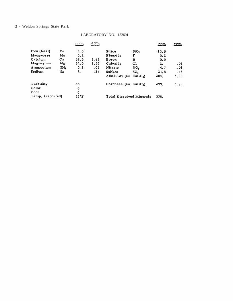
2 - Weldon Springs State Park
LABORATORY NO. 152601

Illinois State Water Survey Bulletin 40 - Supplement II
Three wells are in service for the city of West Chicago (6854).
WELL NO. 1, described in Bulletin 40, is now equipped with 180 ft. of 5-in. column pipe; 8-in., 9-stage Aurora turbine pump, No. 67073, rated at 450 gpm. at 130 ft. T.D.H.; 10 ft. of 5-in. suction pipe; 25-hp. U S electric motor.
The nonpumping water level was reported-ly 91 ft. below the pump base on Apr. 24, 1958.
WELL NO. 2, described in Bulletin 40, was treated on Oct. 16, 1952 with 2750 gal. of 15% HC1. All three wells were shut down. Two hr. after placing the last acid in the well and be-fore pumping was started, the static water level was 86 ft. After 4 hr. pumping at 430 gpm., the drawdown was 82 ft. The water was clear and turned into the system. There was little trace of the acid in Well No. 1.
Well No. 2 is now equipped with 180 ft. of 5-in. column pipe; 8-in., 9-stage Aurora tur-bine pump, No. 65186, rated at 450 gpm, at 130 ft. T.D.H.; 10 ft. of 5-in. suction pipe; 180 ft. of air line (defective); 25-hp. General Electric motor.
WELL NO. 3 was completed in 1950 to a depth of 310 ft. by Layne-Western Co., Aurora, and located about 1000 ft. northwest of Wells No. 1 and 2, or approximately 1000 ft. N. and 1000 ft. W. of the S. E. corner of Section 4, T39N, R9E. The elevation of the top of the well is 762.
The well was cased with 28-in. od. pipe from the surface to 83 ft. and with 24-in. od. pipe from the surface to 86 ft., below which the hole was finished 24 in. in diameter to the bot-tom at 310 ft. The annulus between the casings was cemented by the gravity method. A pro-duction test was conducted on Jan. 24-25, 1950 by representatives of the Driller, City officials, Wells Engineering Co., Consulting Engineers, and the State Water Survey. For test purposes a 4-stage Layne turbine pump, 5 ft. in length, was set on 180 ft. of 6-in. column pipe and pow-ered by a 150-hp. gasoline engine directly con-nected to a Johnston right angle gear drive.
After 22 hr. pumping at a rate of 510 gpm., the drawdown was 40. 5 ft. from a static water level of 72. 5 ft. below the top of the air line (2 ft. above the top of the casing).
WEST CHICAGO DuPage County August 5, 1960
On Aug. 19, 1953 the well capacity had re-ceded from 750 to 375 gpm. with a drawdown of 112 ft. from a nonpumping water level of 88 ft. The well was then' acidized with 3000 gal. of HC1. On Aug. 29, 1953, after 8 hr. pumping at a rate of 800 gpm., the drawdown was 80 ft. from a static level of 88 ft. below the surface.
Well No. 3 is equipped with 250 ft. of 6-in. column pipe; 9-stage Aurora turbine pump, No. 50633, rated at 750 gpm. at 250 ft. T.D.H.; 250 ft. of air line; 60-hp. U S electric motor.
On Apr. 24, 1958, after 12 hr. pumping at a rate of 395 gpm., the drawdown was 90 ft. from a nonpumping water level of 160 ft. below the pump base.
A partial chemical analysis of a sample (Lab. No. 146374) collected Apr. 24, 1958 show-ed the water in Well No. 3 to have a hardness of 22. 6 gr. per gal., total dissolved minerals of 425 ppm., and an iron content of 0. 3 ppm.
WELL NO. 4 was completed in Mar. 1960 to a depth of 1465 ft. by Wehling Well Works, Beecher, and located about 1 1/4 miles southeast of Well No. 3, or approximately 100 ft. S. and 1000 ft. E. of the N. W. corner of Section 15, T39N, R9E. The land surface elevation at the well is 745. 7. The well was cased with 26-in. pipe from the surface to 109 ft. 4 in. and with 20-in. pipe from the surface to 672 ft. (cement-ed in). A 24-in. liner was set from 541 to 585 ft. and a 14-in. liner was set from 962 to 1067 ft., below which the hole was finished 13 1/4 in. in diameter to the bottom.
The pumping equipment consists of 650 ft. of 8-in. column pipe; 12-in., 11-stage Byron Jackson submersible pump, No. 363204, rated at 1000 gpm. at 640 ft. T.D.H.; 650 ft. of air line; 250-hp. electric motor.
On Aug. 4, 1960 water was pumped for 3 hr. at a rate of 530 gpm. with a drawdown of 38 ft. from a nonpumping water level of 400 ft. be-low the top of flange (1.1 ft. above land sur-face).
There are 1755 services, all metered, and 100% of the population served. Pumpage for the city supply is reported (1958) to average 590,000 gpd.

2 - West Chicago
Summary sample study log of WELL NO. 4 furnished by the State Geological Survey

West Chicago - 3
LABORATORY NO. 146374

Illinois State Water Survey Bulletin 40 - Supplement II
The public water supply for the village of Western Springs (10, 838) is described in Bulletin 40 and includes Wells No. 1 and 2.
Since publication of Bulletin 40, new pump-ing equipment has been installed in WELL NO. 1 consisting of 160 ft. of 8-in. column pipe; 12-in., 6-stage Layne turbine pump, No. 6137, rated at 500 gpm. at 135 ft. T.D.H.; 20 ft. of 6-in. suction pipe; 40-hp. General Electric motor. An air line was installed but is reported as defective.
WELL NO. 2 is now equipped with 160 ft. of 7-in. column pipe; 12-in., 6-stage Layne tur-bine pump, No. 26532, rated at 500 gpm. at 135 ft. T .D .H . ; 10 ft. of 6-in. suction pipe;160 ft. of air line; 40-hp. General Electric motor.
On July 7, 1958, during pumping at 500 gpm., the drawdown was 27 ft. from a nonpump-ing water level of 91 ft.
WELL NO. 3 was completed in Feb. 1956 to a depth of 1600 ft. by J. P. Miller Artesian Well Co. , Brookfield, and located at Wolf Road and Johnson Ave. about 200 ft. west of Well No. 2, or approximately 2200 ft. N. and 200 ft. E. of the S. W. corner of Section 5, T38N, R12E. The ground surface elevation at the well is 678.
The well was cased with 28-in. pipe from the surface to 59 ft. and with 20-in. pipe from the surface to 554 ft. The annulus outside the 20-in. casing was filled with cement. An 18-in. liner was set between 1103 and 1203 ft. and a 16-in. inner liner from 1096 to 1336 ft., below which the hole was finished at 15 in. in diameter. Ten shots (total 3237 lb. ) of 100% nitrogel were ex-ploded between 1528 and 1425 ft.
During the drilling operation water levels in the well were observed as shown in Table A.
A production test was conducted by the Driller on Feb. 10-11, 1956. For test pur-poses the pumping equipment consisted of 550 ft. of 8-in. column pipe; 9 l/16-in., 11-stage Peer less test turbine; 200-hp. Westinghouse electric motor. After 30 hr . pumping at a rate
WESTERN SPRINGS Cook County September 23, 1958
of 1000 gpm., the drawdown was 115 ft, from a static level of 440 ft. below the top of the casing.
TABLE A
Depth Depth of to
Drilling Water ft. ft.
215 105 666 400
1275 410 1382 410 1504 412 1600 410 (before shooting) 1600 439 (after shooting)
The permanent pumping equipment install-ed in Aug. 1956 consisted of 650 ft. of 8-in. col-umn pipe; 16-in., 12-stage Layne turbine pump, No. 34112, rated at 900 gpm. at 856 ft. T.D.H.; 10 ft. of 8-in. suction pipe; 300-hp. U S electric motor.
On Aug. 1, 1956, after 7 hr. pumping at 1100 gpm., the drawdown was 127 ft. from a non-pumping water level of 465 ft., and on Aug. 9, 1956 the nonpumping water level was 462 ft. Both readings were by air line measurements.
On July 6, 1958 the well had been backfill-ed to 1256 ft. and the pump lowered to 760 ft. On Aug. 12, 1958, during pumping at 1000 gpm., the drawdown was 100 ft. from a nonpumping water level of 515 ft. A mineral analysis of a sample (Lab. No. 142088) collected Dec. 10, 1957, after 3 hr. pumping at a rate of 800 gpm., showed the water in Well No. 3 to have a hardness of 23.4 gr. per gal . , total dissolved minerals of 664 ppm. , and an iron content of 0. 2 ppm. The r e -ported temperature of 54. 4°F indicated that the water might not be all Galesville water.
In May 1957 it was reported that Well No. 3 furnished most of the municipal water supply.
In 1956 pumpage for Western Springs aver-aged 827,000 gpd.

2 - Western Springs
LABORATORY NO. 142088

Illinois State Water Survey Bulletin 40 - Supplement II
Three wells are in service for the public water supply of the village of Westfield (636) and a new well needs pumping equipment installed.
WELL NO. 1, described in Bulletin 40, has been retired from service.
WELL NO. 2, described in Bulletin 40, has a low water level and is used intermittently.
In Aug. 1952 the east drilled well in the bottom of Well No. 2 was cleaned out by E. C. Baker and Sons, Sigel, to a depth of 70 ft. in an effort to improve the rate of flow into the dug portion of the well. Before the cleaning, the well had filled up to a depth of 49 ft. After clean-ing, a production test proved that the improve-ment in flow was negligible.
WELL NO. 3, described in Bulletin 40, is in 24-hr, daily service.
A 6-in. Test Well No. 1-52 was drilled in Aug. 1952 to a depth of 82 ft. by E. C. Baker and Sons and located west of old Well No. 2. The yield was small and on request of the Driller, the test well was acidized on Sept. 8 and 10 under the supervision of the State Geological Survey. The acidizing, reportedly, caused an enlarge-ment of the hole in the bottom producing forma-tion but no increase in yield. This indicated that the capacity of the artesian system was limited and neither shooting, acidizing, or any other well treatment would likely increase it.
Apparently the well, even though low in yield, was accepted by the village and recon-structed as Well No. 4.
WELL NO. 4 was completed in Oct. 1952 to a depth of 82 ft. by E. C. Baker and Sons and locatedat the site of Test Well No. 1-52 about 300 ft. west of Well No. 2, or approximately 2180 ft. S. and 300 ft. W. of the N. E. corner of Sec-tion 30, TUN, R14W. The ground surface eleva-tion at the well is 700. The well was cased with 6 5/8-in. od. pipe from approximately 5 l/2 ft. above the ground surface to a depth of 52 ft. A 24-in. steel pipe was set around the casing ex-tending from 7 ft. above the ground surface to several feet below the ground surface. A 6-in. envelope of concrete was placed around the steel pipe housing from 6 ft. above the ground surface to a point 10 ft. below the ground surface. Be-
WESTFIELD Clark County April 30, 1959
cause the well site was subject to high waters from a creek (40 ft. to the south of the well) an earth berm was constructed around the well.
The pumping equipment includes a Red Jacket submersible pump, rated at 20 gpm. a-gainst 120 ft. T.D.H. Power is furnished by a 1-hp. electric motor.
In Dec. 1953 it was reported to have been pumped at a rate of 8 gpm. almost continuously for 24 hr. daily.
WELL NO. 5 was completed in Nov. 1957 to a depth of 50 ft. by J. P. Miller Artesian Well Co., Brookfield, and located about 1 mile north-east of Well No. 4, or approximately 2340 ft. N. and 700 ft. E. of the S. W. corner of Section 20. The ground surface elevation at the well is 695. The well was cased with 10-in. pipe to 40 ft. fol-lowed by 10 ft. of 10-in. screen.
Sample study summary log of WELL NO. 5 fur-nished by the State Geological Survey
A production test was conducted on Nov. 27, 1957 by representatives of the Driller, the

2 - Westfield
State Water Survey, and the Consulting Engineer, G. E. DeJong. For test purposes a 12-stage Peerless test turbine pump was powered by a 4-cylinder Red Seal gas engine. After 24 hr. pump-ing at rates gradually decelerated from 100 to 50 gpm., the drawdown was 33 ft. from a static wa-ter level of 3 ft. below the top of the casing (3 ft. above ground level).
A partial chemical analysis of a sample (Lab. No. 145154) collected Nov. 27, 1957, after
8 hr. pumping at a rate of 809 gpm., showed the water in Well No. 5 to have a hardness of 26.1 gr. per gal., total dissolved minerals of 451 ppm., an iron content of 4.7 ppm., and a tur-bidity of 69 ppm.
The pumping equipment had not been in-stalled as of this report.
Pumpage for the village in July 1958 aver-aged 18, 000 gpd.
LABORATORY NO. 145154

Illinois State Water Survey Bulletin 40 - Supplement II
Three wells are in service for the public water supply of the village of Westmont (5997).
WELL NO. 1, described in Bulletin 40, has been abandoned.
WELL NO. 2 is described in Bulletin 40. In Aug. 1957 the 118-ft. air line was reported to be defective. In May 1959 the nonpumping water level was reported to be 152 ft. and the draw-down was 4 ft.
WELL NO. 3, described in Bulletin 40, was equipped in May 1957 with 180 ft. of 5-in. column pipe; 8-in., 9-stage Layne turbine pump (No. 36892), 6 ft. 2 in. long; 10 ft. of 6-in. suc-tion pipe; 180 ft. of air line; 25-hp. U S electric motor.
In May 1959 the nonpumping water level was reportedly 133 ft. and the drawdown was 13 ft.
WELL NO. 4 was completed in Jan. 1958 to a depth of 313 ft. by Layne-Western Co., Aurora, and located about 1/2 mile north of Well No. 3, or approximately 2425 ft. S. and 465 ft. E.
WESTMONT DuPage County May 5, 1959
of the N. W. corner of Section 10, T38N, R11E. The elevation of the ground surface at the well is 757.
The well was cased with 12-in. steel pipe with welded joints from 2 ft. above the surface to 151 ft. The hole was finished 12 in. in diam-eter from the bottom of the casing to the bottom of the hole at 313 ft. The top 15 ft. of the casing was cemented in. Upon completion of the well, the Driller reported that, after 11 hr. pumping at a rate of 259 gpm., the drawdown was 27 ft. from a static water level of 128 ft.
The permanent pumping equipment includes a Layne turbine pump, rated at 270 gpm. with power from a 20-hp. electric motor.
A mineral analysis of a sample (Lab. No. 145601) collected Jan. 25, 1958 showed the water in Well No. 4 to have a hardness of 26. 2 gr. per gal., total dissolved minerals of 628 ppm., an iron content of 29 ppm., and a turbidity of 2500 ppm.
Pumpage for 1957 averaged 320, 000 gpd.
LABORATORY NO. 145601

Illinois State Water Survey Bulletin 40 - Supplement II
Four wells are in service for the public water supply of the city of Wheaton (24,312). When Old Well No. 1 was abandoned, new num-bering was given to the wells.
OLD WELL NO. 1, described in Bulletin 40 as abandoned, has been filled and capped. All sign of the well has been obliterated.
WELL NO. 1 was described in Bulletin 40 as Well No. 2. In Apr. 1958 the nonpumping wa-ter level was 47 ft. and the drawdown, during pumping, was 50 ft.
WELL NO. 2 was described in Bulletin 40 as Well No. 3. In Apr. 1958 the nonpumping wa-ter level was 54 ft. and the drawdown was 20 ft.
WELL NO. 3 was described in Bulletin 40 as Well No. 4. In Apr. 1958 the nonpumping wa-ter level was 55 ft. and the drawdown was 42 ft.
WELL NO. 4 was completed in 1954 to a depth of 341 ft. by Layne-Western Co., Aurora, and located about 1/4 mile north and l/2 mile east of Well No. 3, near the corner of Country Side Drive and Irving Park Road, or approxi-mately 1775 ft. S. and 1150 ft. W. of the N. E. corner of Section 9, T39N, R10E. The elevation of the ground surface at the well is 750. The
WHEATON DuPage County September 16, 1959
well was cased with 20-in. pipe from the surface to 105 ft., below which the hole was finished 19 in. in diameter to the bottom at 341 ft. A pro-duction test was conducted on Oct. 27-28, 1954 by representatives of the Driller and the State Water Survey. After 15 hr. pumping at a rate of 799 gpm., the drawdown was 53 ft. from a nonpump-ing water level of 45 ft. (air line readings). Three and one-half hr. after pumping was stopped, the water level had recovered to 51 ft.
The permanent pumping equipment con-sists of 220 ft. of 8-in. column pipe; 12-in., 6-stage Layne turbine pump, No. 34613, rated at 700 gpm. at 384 ft. T.D.H.; 10 ft. of 8-in. suc-tion pipe; 220 ft. of air line; 100-hp. Westing-house electric motor.
Analysis of a sample (Lab. No. 150615) col-lected Sept. 16, 1959 showed the water in Well No. 4 to have a hardness of 25.6 gr. per gal., total dissolved minerals of 528 ppm., and an iron content of 1.1 ppm.
Nonpumping water levels for the Wheaton wells are shown in Table A.
Pumpage for the city wells in July, Aug. Sept., and Oct. of 1957 averaged 1. 77 mgd.
TABLE A
Nonpumping Water Levels
* Old Well No. 1 (abandoned 1930) ** No. 2 on

2 - Wheaton
LABORATORY NO. 150615

Illinois State Water Survey Bulletin 40 - Supplement II
Water for the Wheaton Farms (unincorpor-ated-est. 350) community is obtained from one well.
WELL NO. 1, described in Bulletin 40, is now equipped with a Byron Jackson turbine pump, set at 110 ft. and rated at 50 gpm. against 160 ft. T.D.H. The power for pumping is furnished by a 5-hp. U S electric motor.
Since a 2-ft. section of casing has been welded on the top of the old one, the casing now
WHEATON FARMS DuPage County August 16, 1957
extends 2 ft. above the floor of the 7 ft. by 7 ft. concrete pit, which is 5 ft. deep.
On Oct. 30, 1956 the nonpumping water lev-el was reportedly 75 ft., and the drawdown dur-ing pumping was 15 ft.
There were 96 services in 1957, all metered, and all but two homes were served.
Pumpage for 1958 averaged 11, 367 gpd.

Illinois State Water Survey Bulletin 40 - Supplement II
Since publication of Bulletin 40, two addi-tional wells have been constructed for the village of Wheeling (7169). Water for the village is ob-tained from three wells.
WELL NO. 1, described in Bulletin 40 as located in Section 12, T42N, R12E, is actually at R11E. The pumping equipment in Well No. 1 now consists of 80 ft. of 5-in. column pipe; 8-in., 9-stage Aurora turbine pump, No. 30159, rated at 200 gpm. at 200 ft. T.D.H.; 20 ft. of 5-in. suction pipe; 15-hp. U S electric motor; 80 ft. of air line.
Well No. 1 is in daily service. On Oct. 14, 1958 the nonpumping water level was 43.2 ft. Water from Well No. 1 is pumped directly into the mains.
WELL NO. 2 was completed in 1955 to a depth of 245 ft. by J. P. Miller Artesian Well Co., Brookfield, and located in Dunhurst Heights Subdivision at the intersection of S. Wayne and E. Wayne St., about 1 1/4 miles southwest of Wheel-ing Well No. 1, or approximately 2300 ft. S. and 400 ft. W. of the N. E. corner of Section 10, T42N, R11E. This well was originally owned by Herzog Construction Co. for the Dunhurst Heights Subdivision but was subsequently taken over by the village and designated Village Well No. 2. The elevation of the ground surface at the well is 646. The well was cased with 16-in. pipe to a depth of 104 ft., below which the hole was finish-ed 16 in. in diameter to the bottom.
Correlated driller's log of Wheeling WELL NO. 2 furnished by the State Geological Survey
A production test was conducted on July 14, 1955 by representatives of the Drilling Con-tractor and the State Water Survey. A Peerless turbine pump was used for test purposes. After 12 hr. pumping at a rate of 135 gpm., the draw-
WHEELING Cook County December 22, 1958
down was 130 ft. from a nonpumping water level of 20 ft. below the top of the casing.
A partial analysis of a sample (Lab. No. 138149) collected on July 14, 1955, after 12 hr. pumping, showed the water to have a hardness of 9 ppm., total dissolved minerals of 356 ppm., and an iron content of 0. 3 ppm.
A few days later the well was acidized with 4000 gal. after which a second production test was conducted on July 23 by the Driller. After 7 1/2 hr. pumping at a rate of 174 gpm., the drawdown was 110 ft. from a nonpumping water level of 40 ft. The pumping test equipment consisted of 155 ft. of 6-in. column pipe; 10-in., 5-stage Peerless turbine test pump driven from a Buda engine; 155 ft. of air line.
A partial analysis of a sample (Lab. No. 138282) collected July 27, 1955 showed the water in Well No. 2 to have a hardness of 71.1 gr. per gal., total dissolved minerals of 2280 ppm., and an iron content of 19 ppm.
When the sample (Lab. No. 138282) was col-lected on July 27, the pump had been operated for 4 hr. at a rate of 145 gpm. The drawdown was 78 ft. from a nonpumping water level of 50 ft. be-low the top of the casing.
Subsequently, the permanent pump assem-bly was installed as follows: 200 ft. of 5-in. col-umn pipe; 8-in., 8-stage Peerless turbine pump, No. 115361, rated at 170 gpm. against 175 ft. T.D.H.; 20 ft. of 5-in. suction pipe; 200 ft. of air line; 15-hp. U S electric motor.
A partial analysis of a sample (Lab. No. 148229) collected Nov. 17, 1958 showed the water in Well No. 2 to have a hardness of 18. 2 gr. per gal., total dissolved minerals of 538 ppm., and an iron content of 0. 3 ppm.
Well No. 2 supplies the western part of Wheeling, about 60% of the population. Water from Well No. 2 is pumped into a 300, 000-gal. impounding reservoir.
WELL NO. 3 was completed in June 1956 to a depth of 1370 ft. by J. P. Miller Artesian Well Co. and located at the corner of Sunset and Manchester in Meadowbrook Subdivision, about 3/8 mile east of Well No. 2, or approximately 2400 ft. S. and 1700 ft. E. of the N. W. corner
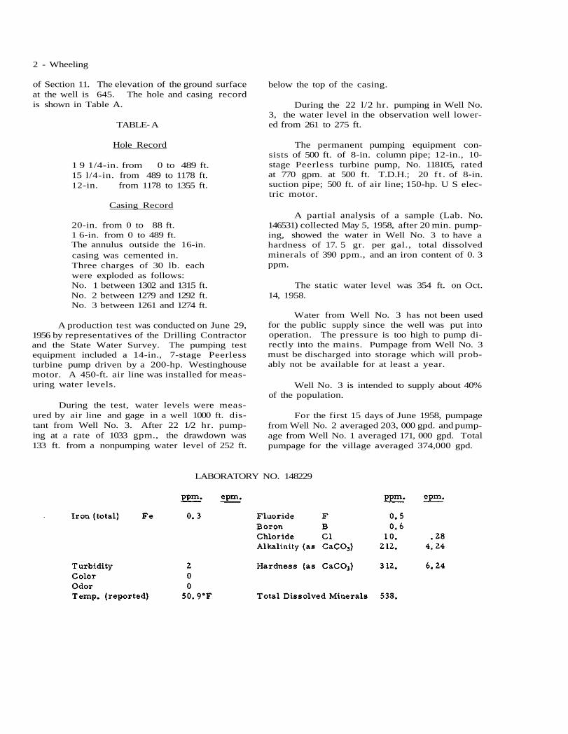
2 - Wheeling
of Section 11. The elevation of the ground surface at the well is 645. The hole and casing record is shown in Table A.
TABLE- A
Hole Record
1 9 1/4-in. from 0 to 489 ft. 15 l/4-in. from 489 to 1178 ft. 12-in. from 1178 to 1355 ft.
Casing Record
20-in. from 0 to 88 ft. 1 6-in. from 0 to 489 ft. The annulus outside the 16-in. casing was cemented in. Three charges of 30 lb. each were exploded as follows: No. 1 between 1302 and 1315 ft. No. 2 between 1279 and 1292 ft. No. 3 between 1261 and 1274 ft.
A production test was conducted on June 29, 1956 by representatives of the Drilling Contractor and the State Water Survey. The pumping test equipment included a 14-in., 7-stage Peerless turbine pump driven by a 200-hp. Westinghouse motor. A 450-ft. air line was installed for meas-uring water levels.
During the test, water levels were meas-ured by air line and gage in a well 1000 ft. dis-tant from Well No. 3. After 22 1/2 hr. pump-ing at a rate of 1033 gpm., the drawdown was 133 ft. from a nonpumping water level of 252 ft.
below the top of the casing.
During the 22 l/2 hr. pumping in Well No. 3, the water level in the observation well lower-ed from 261 to 275 ft.
The permanent pumping equipment con-sists of 500 ft. of 8-in. column pipe; 12-in., 10-stage Peerless turbine pump, No. 118105, rated at 770 gpm. at 500 ft. T.D.H.; 20 f t . of 8-in. suction pipe; 500 ft. of air line; 150-hp. U S elec-tric motor.
A partial analysis of a sample (Lab. No. 146531) collected May 5, 1958, after 20 min. pump-ing, showed the water in Well No. 3 to have a hardness of 17. 5 gr. per gal., total dissolved minerals of 390 ppm., and an iron content of 0. 3 ppm.
The static water level was 354 ft. on Oct. 14, 1958.
Water from Well No. 3 has not been used for the public supply since the well was put into operation. The pressure is too high to pump di-rectly into the mains. Pumpage from Well No. 3 must be discharged into storage which will prob-ably not be available for at least a year.
Well No. 3 is intended to supply about 40% of the population.
For the first 15 days of June 1958, pumpage from Well No. 2 averaged 203, 000 gpd. and pump-age from Well No. 1 averaged 171, 000 gpd. Total pumpage for the village averaged 374,000 gpd.
LABORATORY NO. 148229

Wheeling - 3
Sample study summary log of WELL NO. 3 furnished by the State Geological Survey

Illinois State Water Survey Bulletin 40 - Supplement II
Water for the public supply of Wildwood Subdivision (est. 1800) on Gages Lake is obtained from three wells. The subdivision lies north and east of the intersection of Routes 20 and 45. The system is operated by the John Rule Lake County Water Co.
Prior to 1950, Henry Boysen, Libertyville, drilled about 12 wells in this area. Seven of the wells were finished in sand and gravel and pro-duced at least 150 gpm. Wells No. 1 and 3 were drilled as a result.
WELL NO. 1 was completed to a depth of 145 ft. in Apr. 1950 by Henry Boysen and located approximately 470 ft. S. and 700 ft. E. of the N. W. corner of Section 31, T45N, RUE. The ground surface elevation at the well is 814. The well was cased with 6-in. pipe to 134 ft. followed by 11 ft. of 6-in. Cook red brass screen.
The pumping equipment consists of 110 ft. of 3 l/2-in. column pipe; 5 5/8-in., 18-stage Cook turbine pump, No. 11845, rated at 50 gpm.; 10 ft. of 3 l/2-in. suction pipe; 110 ft. of air line; 5-hp. U S electric motor.
In Mar. 1952 the well reportedly supplied about 30 gpm.
WELL NO. 2 was completed to a depth of 1311 ft. in July 1951 (deepened in 1952 to 1570 ft. and in 1959 to 1845 ft. ) by Henry Boysen and lo-cated about 1/4 mile north of Well No. 1, or ap-proximately 600 ft. N. and 75 ft. E. of the S. W. corner of Section 29. The ground surface eleva-tion at the well is 790. The well was cased with 14-in. pipe from the surface to 183 ft. and with 10-in. pipe from the surface to 583 ft., below which the hole was finished 10 in. in diameter to the bottom. The 10-in. casing was cemented in.
In July 1951 a production test was conducted by the Driller, using a vertical turbine pump set at 320 ft. After 2 hr. pumping at a rate of 141 gpm., the drawdown was 105 ft. from a static water level of 216 ft. below the surface. In July 1953 the nonpumping water level was 240 ft. be-low the surface.
The pumping equipment, installed in July 1951, consists of a Pomona turbine pump, No.
WILDWOOD SUBDIVISION Lake County April 20, 1959
SR1112, rated at 300 gpm. and connected to a 40-hp. Westinghouse electric motor.
A mineral analysis of a sample (Lab. No. 125913) collected July 18, 1951, after 2 hr. pump-ing at a rate of 141 gpm., showed the water in Well No. 2 to have a hardness of 16. 3 gr. per gal., total dissolved minerals of 360 ppm., and an iron content of 2 ppm.
After the well was deepened in May 1952 from 1311 ft. to 1570 ft., a production test was conductedbyHenryBoysen. After 6 1/2 hr. pump-ing at a rate of 297 gpm., the drawdown was 136 ft, from a nonpumping water level of 207 ft. be-low the surface.
The McCullough Tool Co. reportedly logged and shot the well in Jan. 1959 at four levels. Two hundred fifty shots were set off at two per ft. as follows: 1790-1760 ft.; 1734-1714 ft.; 1684-1674 ft.; 1480-1415 ft.
In Mar. 1959 the depth of the well was 1845 ft. and the nonpumping water level was reportedly 247 ft. below the surface. A partial chemical analysis of a sample (Lab. No. 149006) collected after 7 hr. pumping at a rate of 590 gpm., show-ed the water in Well No. 2 to have a hardness of 16. 3 gr. per gal., total dissolved minerals of 325 ppm., and an iron content of 0. 8 ppm.
WELL NO. 3 was completed to a depth of 173 ft. in 1952 by Henry Boysen and located near the south end of John Mogg Road West, about 1/2 mile east of Well No. 1, or approximately 600 ft. S. and 2326 ft. W. of the N. E. corner of Section 31. The ground surface elevation at the well is 827. The lower 30 ft. of the hole penetrated clean gravel. The well was cased with 6-in. pipe from the surface to 160 ft. followed by 13 ft. of 6-in. screen. The upper 6 1/2 ft. of the screen has No. 14 slot openings and the lower 6 1/2 ft. has No. 18 slot openings. On Mar. 1, 1952, dur-ing pumping at a rate of 162 gpm., the drawdown was 7 1/2 ft. from a static water level of 97 ft. below the surface.
The permanent pump assembly installed in Nov. 1952, consists of 150 ft. of 4-in. column pipe; 6-in., (?)-stage Cook turbine pump, No. C272377LAW; 150 ft. of air line; 20-hp. U S elec-tric motor.

2 - Wildwood Subdivision
On Dec. 20, 1953 the Driller reportedpump-ing at a rate of 201 gpm. with a drawdown of 6 ft. from a static water level of 108 ft. below the pump base.
A partial chemical analysis of a sample (Lab. No. 148237) collected Nov. 20, 1958 show-
ed the water in Well No. 3 to have a hardness of 8. 9 gr . per gal . , total dissolved minerals of 301 ppm., and an iron content of 0.1 ppm.
In 1955 there were 508 services, 250 of which were metered. Pumpage is estimated to average 120, 000 gpd.
LABORATORY NO. 148237
LABORATORY NO. 149006

Wildwood Subdivision - 3
Summary sample study log of WELL NO. 2 furnished by the State Geological Survey

Illinois State Water Survey Bulletin 40 - Supplement II
Two wells are in service for the public supply of the village of Willisville (532).
WELL NO. 1 is described in Bulletin 40.
WELL NO. 2 was completed in 1955 to a depth of 555 ft. by L. W. Gwin Drilling Co., Percy, and located in the southwest part of town, approximately 1300 ft. S. and 100 ft. E. of the N. W. corner of Section 30, T6S, R4W. The ground surface elevation at the well is 500. The well was cased with 8-in. pipe to 278 ft. (cement-ed in), below which the hole was finished 8 in, in diameter. Sandstone was reportedly penetrated at 276 ft.
A production test was conducted on July 13, 1954 by representatives of the Driller and the State Water Survey. The air line was inoperable.
WILLISVILLE Perry County March 3, 1958
However, the nonpumping water level was ap-proximately 160 ft. and the pump performance curve showed a water level of 240 ft. during pumping at a rate of 90 ft.
The permanent pump is a Jacuzzi submers-ible set at 294 ft. and rated at 100 gpm. A 10-hp. electric motor is installed.
A mineral analysis of a sample (Lab. No. 145895) collected Mar. 3, 1958 showed the water in Well No. 2 to have a hardness of 12. 9 gr. per gal., total dissolved minerals of 313 ppm., and an iron content of 0. 4 ppm.
Reportedly, about 98% of the population is served through 220 services, all metered. Pump-age is estimated to average 35,000 gpd.
LABORATORY NO. 145895

Illinois State Water Survey Bulletin 40 - Supplement II
A public water supply was installed in 1959 for Willowick Estates, a subdivision owned by Sherry Builders and located near Oak Forest. The subdivision, when completed, is to be a part of Oak Forest.
WELL NO. 1 was completed to a depth of 455 ft. in Aug. 1959 by Wehling Well Works, Beecher, and located 700 ft. N. and 1375 ft. E. of the S. W. corner of Section 22, T36N, R13E. The elevation of the ground surface at the well is 660. The well was cased with 16-in. od. pipe from the surface to 84 ft., below which the hole was finished 15 in. in diameter to the bot-tom. The top of the limestone was penetrated at 45 ft. depth below the surface.
A production test was conducted on July 27, 1959, after which the pump was removed and four applications of 55 gal. each of HC1 (total 220 gal. ) were poured into the well through a 2-in. pipe, 100 ft. in length. After each application
WILLOWICK ESTATES Cook County September 9, 1960
the well wall was "scratched" and the well was surged and baled. After the acid treatment a larger pump assembly and engine were installed on Aug. 14 consisting of 347 ft. of 6-in. column pipe; 12-in., 15-stage American Well Works tur-bine pump; 347 ft. of air line; 150-hp. LeRoi engine.
On Aug. 5, 1959, after 1 l/2 hr. pumping at a rate of 350 gpm., the drawdown was 113 ft. from a nonpumping water level of 32 ft.
A mineral analysis of a sample (Lab. No. 151277) collected from Well No. 1 showed the wa-ter to have a hardness of 29. 8 gr. per gal., total dissolved minerals of 669 ppm., and an iron con-tent of 1. 4 ppm.
Pumpage for the subdivision is not known as no records are yet available. The number of services is not known.
LABORATORY NO. 151277

Illinois State Water Survey Bulletin 40 - Supplement II
Four wells are in service for the city of Winchester (1657).
WELL NO. 1, described in Bulletin 40, was abandoned in 1949.
WELLS NO. 2 and 3, described in Bulletin 40, are in service.
WELL NO. 4 was completed in Oct. 1949 to a depth of 47 ft. by Hayes and Sims, Cham-paign, and located at the site of Test Hole No. 1-49, about l/2 mile southwest of Well No. 3, or approximately 1320 ft. S. and 2000 ft. W. of the N. E. corner of Section 5, T13N, R12W. The elevation of the ground surface at the well is 463. 3. The well was cased with 16-in. pipe to 37 ft. 7 in. and with 8-in. id. pipe from 1 1/2 ft. above to 36 ft. 3 in. below the ground level, fol-lowed by an 8-in. Johnson Everdur screen, 11 ft. long, and with No. 60 slot openings. The annu-lus between the casings and between the screen and the wall of the hole was gravel packed.
A production test was conducted on Oct. 27, 1949 by representatives of the Driller, the State Water Survey, and Crawford, Murphy, and Tilly, Consulting Engineers. An air line, 29.5 ft. long, was installed from the top of the casing for meas-uring water levels. After 7 hr. pumping at 165 gpm., the drawdown was 18. 3 ft. from a static water level of 9. 5 ft. The pump was then oper-ated for 30 min. at 225 gpm. when the water was drawn down to 29. 5 ft., the bottom of the air line. Forty-five min. after the pump was stop-ped, the water level had recovered to 12. 5 ft.
During the test, water levels were observed in two 2-in. test holes located (Test Hole No. 1) at 117.9 ft. south of the pumped well and (Test Hole No. 2) at 334. 8 ft. south of the pumped well.
When the test was concluded the water lev-el in Test Hole No. 1 had lowered 9. 2 ft. from a static level of 6. 8 ft. below the top of the 2-in. casing (elev. 464).
In Test Hole No. 2 the water level had low-ered 5.1 ft. from a static level of 9.6 ft. below the top of the 2-in. casing (elev. 466. 5).
After the well was accepted the top of the casing was extended above high water level in a nearby creek (elev. 472. 5). The well was e-quipped with 30 ft. of 4-in. column pipe; 5 5/8-in., 3-stage Aurora turbine pump (No. 46721), 6 ft. 2 1/4 in. long, rated at 125 gpm. at 122 ft.
WINCHESTER Scott County January 28, 1957
T.D.H.; 13 5/8-in. length of strainer; 35 ft. of air line; 7 1/2-hp. electric motor.
WELL NO. 5 was completed in Nov. 1949 to a depth of 50 ft. by Hayes and Sims and lo-cated about 270 ft. south of Well No. 4, or ap-proximately 1590 ft. S. and 2000 ft. W. of the N. E. corner of Section 5. The well was cased with 16-in. od. pipe from the surface to 41 ft. 5 in. and an 8-in. id. pipe was set from 1 ft. above to 39 ft. 10 in. below ground level, followed by a 10 ft. length of Johnson Everdur screen having No. 60 slot openings. The annulus between the casings and between the screen and the wall of the hole was packed with select gravel.
A production test was conducted on Nov. 9, 1949 by representatives of the Driller, the State Water Survey, and the Consulting Engineers. After 8 hr. pumping at 100 gpm., the drawdown was 25 ft. from a nonpumping water level of 9. 3 ft. (An air line was installed at a length of 37 ft. below the top of the casing. ) Two and one-half hr. after pumping was stopped, the water level in Well No. 4 had returned to 11 ft.
Water levels were observed, during the test, in the same two test holes as used in the test of Well No. 4. Test Hole No. 1 was 152.1 ft. north of the pumped well (No. 4) and Test Hole No. 2 was 64. 8 ft. north of the pumped well. When pumping in Well No. 5 was stopped, the water level in Test Hole No. 1 had lowered to 11. 5 ft. from a static level of 6. 6 ft. below the top of the 2-in. casing (elev. 464). Two and one-half hr. later the water level had returned to 8 ft.
When pumping in Well No. 5 was stopped, the water level in Test Hole No. 2 had lowered to 15. 6 ft. from a static level of 9. 7 ft. below the top of the 2-in. casing (elev. 466. 5). Two and one-half hr. later the water level had raised to 11 ft.
Well No. 5 is equipped with 40 ft. of 4-in. column pipe; 5 5/8-in., 8-stage Aurora turbine pump (No. 46722), 4 ft. 1 l/4 in. long, and rated at 90 gpm. at 100 ft. T.D.H.; 13 5/8 in. of strain-er; 40 ft. of air line; 5-hp. electric motor.
After the well was accepted the casing was extended upwards, similar to Well No. 4, and the top of the air line at the top of the casing was at elevation 472. 5.
Pumpage in Jan. 1957 was reported to av-erage 95,000 gpd.

Illinois State Water Survey Bulletin 40 - Supplement II
Four wells are in service for the city of Windsor (1021).
WELL NO. 1 was described in Bulletin 40 as being drilled in 1934 to a depth of 100 ft. 10 in. at the site of Test Well No. 6. The well was out of service for several years, but was returned to service in 1957 after being equipped with a new Jacuzzi turbine pump, rated at 60 gpm.
WELL NO. 2 was completed in Feb. 1949 to a depth of 131 ft. 5 in. by Hayes and Sims, Cham-paign, and located 10 ft. south of Test Well No. 11, described in Bulletin 40. Well No. 2 is located in town near the corner of Virginia and Pine St., or approximately 1550 ft. N. and 2325 ft. E. of the S. W. corner of Section 36, T12N, R6E. The ground surface elevation at the well is 708. The well was cased with 12-in. id. pipe from 2 ft. above to 119 ft. 9 1/2 in. followed by 10 ft. 11 in. of 11 l/4-in. od. Johnson Everdur screen having No. 25 slot openings.
A production test was conducted on Feb. 22, 1949 by representatives of the Driller, the State Water Survey, and Wilson and Anderson, Con-sulting Engineers. After 7 hr. pumping at 33. 5 gpm., the drawdown was 87 ft. from a nonpump-ing water level of 30. 6 ft. below the top of the casing. One hr. after the pump was stopped, the water level had recovered to 54. 5 ft.
The pump presently installed in Well No. 2 is a Jacuzzi turbine with a capacity of 18-20 gpm.
WINDSOR Shelby County January 13, 1958
WELL NO. 3 was completed in 1951 to a depth of 99 ft. 9 in. by E. C. Baker and Sons, Sigel, and located about 30 ft. west of Well No. 1, or approximately 75 ft. S. and 1285 ft. E. of the N. W. corner of Section 12, T11N, R5E. The ground surface elevation at the well is 720. The well was cased with 7 l/2-in. od. pipe from 2 ft. above to 93 ft. 5 in. below the surface followed by 6 ft. 2 in. of slotted pipe screen (l/8-in. slots).
The permanent pump is a Red Jacket sub-mersible rated at 40 gpm. against 180 ft. T.D.H., with power from a 3-hp. electric motor.
A mineral analysis of a sample (Lab. No. 145470) collected Jan. 10, 1958 showed the water in Well No. 3 to have a hardness of 20 gr. per gal., total dissolved minerals of 446 ppm., and an iron content of 6 ppm.
WELL NO. 4 was completed in May 1952 to a depth of 99 ft. 9 in. by E. C. Baker and Sons and located about 150 ft. west of Well No. 1, or approximately 50 ft. S. and 1150 ft. E. of the N. W. corner of Section 12. The well was cased with 7 l/2-in. od. pipe from 2 ft. above to 89 ft. 2 in. below ground level followed by a 6-ft. section of slotted pipe (l/8-in. slots).
The permanent pump assembly is similar to the installation in Well No. 3.
In 1957 there were 375 services, all but 26 metered. Pumpage was estimated in 1957 to av-erage 91, 800 gpd.
LABORATORY NO. 145470

Illinois State Water Survey Bulletin 40 - Supplement II
Water for the public supply of Winfield (1575) is obtained from two wells.
WELL NO. 1, described in Bulletin 40, is now equipped with a Layne turbine pump, rated at 150 gpm. at 75-psi. discharge pressure, di-rectly connected to a 15-hp. U S electric motor,
WELL NO. 2 was completed in Mar. 1957 to a depth of 335 ft. by Layne-Western Co., Aurora, and located at the corner of Williams and Lincoln, about 3/4 mile south of Well No. 1, or approximately 1400 ft. N. and 1600 ft. E. of the S. W. corner of Section 13, T39N, R9E. The elevation of the ground surface at the well is 778.
The well is cased with 12-in. steel pipe to 133 ft., below which the hole was finished 12 in. in diameter.
The Driller reported a pumping test was conducted on Mar. 16, 1957. A 10-in., 7-stage Layne test pump was installed with a 6-in. col-umn pipe and 235 ft. of air line; a Chrysler en-gine furnished the power. After 8 hr. pumping at a rate of 523 gpm., the drawdown was 1 ft. from a static water level of 85 ft. below the top of the casing (1. 5 ft. above ground level).
The permanent pumping equipment, in-stalled in the summer of 1957, includes 135 ft. of 8-in. column pipe; 10-in., 4-stage Byron Jackson turbine pump, No. 346589, rated at 800 gpm. at 100 ft. T.D.H.; 10 ft. of 8-in. suction pipe; 135 ft. of air line; 30-hp. U S electric mo-tor.
On Oct. 17, 1958, during pumping at 400 gpm. for 3 hr. , the drawdown was 5 ft. from a nonpumping water level of 85 ft. below the pump base.
WINFIELD DuPage County September 9, 1960
A mineral analysis of a sample (Lab. No. 148010) collected Oct. 17, 1958, after 3 hr. pump-ing at 400 gpm., showed the water in Well No. 2 to have a hardness of 27. 2 gr. per gal., total dissolved minerals of 580 ppm., and an iron content of 0. 5 ppm.
Pumpage in 1958 was reported to average 75,000 gpd.
Sample study summary log of WELL NO. 2 fur-nished by the State Geological Survey

2 - Winfield
LABORATORY NO. 148010
WHEATON PARK MANOR
The public water supply of the Wheaton Park Manor Subdivision has been reportedly-taken over by the village of Winfield.
WELL NO. 1, located at the northeast cor-ner of Williams and Madison St., is now aban-
doned. The well was drilled about 1924 to a r e -ported depth of 180 ft. and cased with 6-in. pipe to an unknown depth.
WELL NO. 2 was completed about Aug. 1955 to a depth of 263 ft. by N. H. Geltz, Aurora, and located about 35 ft. east of Well No. 1. The well is being maintained as a stand-by unit.

Illinois State Water Survey Bulletin 40 - Supplement II
Since July 1959 the village of Winthrop Harbor (3848) has purchased its public water supply from Lake County Public Water District. Prior to 1959, five wells had been constructed for the village supply and at the time of connect-ing to the Public Water District, WELLS NO. 1, 2 and 3, all described in Bulletin 40, had been abandoned.
WELL NO. 4 was completed to a depth of 138 ft. in 1948 and located at Sixth and College, about 2 blocks north of the water tank in the northwest portion of the village, or approximate-ly 650 ft. S. and 300 ft. W. of the N. E. corner of Section 9, T46N, R12E. The ground surface elevation at the well is 650. The well was cas-ed with 8-in. pipe from 2 ft. above the pump house floor to he bottom of the well.
The pumping equipment consists of an American Well Works turbine pump, rated at 150 gpm. against 200 ft. T.D.H. connected to a 10-hp. U S electric motor.
Well No. 4 has been maintained for emer-gency use since July 1959 when the village began purchasing water from the Water District.
WELL NO. 5 was completed about 1953 to a depth of 130 ft. by Ausherman and Clark, Zion, and located close to the lake shore about 1/2 mile
WINTHROP HARBOR Lake County January 28, 1960
southeast of Well No. 4, or approximately 2000 ft. N. and 2000 ft. E. of the S. W. corner of Section 10. The ground surface elevation at the well is 600. The well was cased with 8-in. pipe to rock at 95 ft., below which the hole was finish-ed at 6 in. in diameter to the bottom at 130 ft.
When the well was completed, water was pumped at a rate of 250 gpm. with a drawdown of 50 ft. from a static water level of 10 ft. below the top of the casing.
The pumping equipment includes 85 ft. of 5-in. column pipe; 8-in., 4-stage Byron Jackson submersible pump, rated at 160 gpm. against 160 ft. T.D.H.; 85 ft. of air line; 15-hp. electric mo-tor.
A partial analysis of a sample (Lab. No. 148586) collected in Jan. 1958, while pumping at a rate of 250 gpm., showed the water in Well No. 5 to have a hardness of 7 gr. per gal., total dis-solved minerals of 235 ppm., and an iron con-tent of 0.1 ppm.
In July 1958, when Winthrop Harbor was using water from two wells, pumpage averaged 150, 000 gpd. In the last six months of 1959 after the wells had been retired, the village was pur-chasing 158, 000 gpd. from the Lake County Pub-lic Water District.
LABORATORY NO. 148586

Illinois State Water Survey Bulletin 40 - Supplement II
One well is in service for the public water supply of the Wooded Shores Subdivision (est. 300). The well and system, formerly owned by Mr. G. W. Wickline, is now owned by Mr. T. P. Mathews, Realtor, Wonder Lake. The subdivision is located on the eastern shore of Wonder Lake.
WELL NO. 1 was completed in 1934 to a depth of 87 ft. by Art Wertz, Antioch, and locat-ed approximately 1150 ft. N. and 900 ft. E. of the S. W. corner of Section 18, T45N, R8E. The ground surface elevationat the well is 820. The well was cased with 6-in. pipe.
The pumping equipment, installed new in 1958, consists of 30 ft. of 2 l/2-.in. column pipe; Sta-Rite submersible pump, rated at 60 gpm.;
WOODED SHORES SUBDIVISION McHenry County October 28, 1958
5-hp. electric motor.
On Oct. 28, 1958, during pumping at a rate of 60 gpm., the drawdown was 6 ft. from a non-pumping water level of 4 ft. below the top of the casing.
A partial chemical analysis of a sample (Lab. No. 148175) collected Oct. 28, 1958, after pumping began, showed the water in Well No. 1 to have a hardness of 28. 8 gr. per gal., total dis-solved minerals of 521 ppm., and a trace of iron.
There are 85 services, none of which is metered. Pumpage is estimated to average 18,000 gpd.
LABORATORY NO. 148175

Illinois State Water Survey Bulletin 40 - Supplement II
Seven wells are in service for the public water supply of the city of Wood River (11, 694).
WELLS NO. 1 to 8 inclusive and WELLS NO. 11 and 13, as described in Bulletin 40, have been abandoned.
WELL NO. 9, described in Bulletin 40, is in service. A partial chemical analysis of a sample (Lab. No. 136978) collected Feb. 9, 1955 showed the water in Well No. 9 to have a hardness of 20. 8 gr. per gal., total dissolved minerals of 370 ppm., and an iron content of 0.4 ppm.
WELL NO. 10, described in Bulletin 40, is in service.
WELL NO. 12, described in Bulletin 40, is in service. A mineral analysis of a sample (Lab. No. 148792) collected Feb. 6, 1959 showed the water in Well No. 12 to have a hardness of 27 gr. per gal., total dissolved minerals of 556 ppm., and an iron content of 1 ppm.
WELL NO. 13 was abandoned in 1959. A mineral analysis of a sample (Lab. No. 148793) collected Feb. 9, 1959 showed the water in Well No. 13 to have a hardness of 26. 3 gr. per gal., total dissolved minerals of 544 ppm., and an iron content of 0. 4 ppm.
WELL NO. 14 was completed to a depth of 112 ft. in May 1952 by Harold Watson, East St. Louis, and located approximately 3140 ft. N. and 1080 ft. E. of the S. W. corner of Section 26, T5N, R9W. The elevation of the ground surface at the well is 440. Well No. 14 is reportedly identical with Well No. 13.
A partial chemical analysis of a sample (Lab. No. 143395) collected May 17, 1957, after 1 hr. pumping (the pump had not been operated for 1 yr.), showed the water in Well No. 14 to have a hardness of 25. 2 gr. per gal., total dis-solved minerals of 530 ppm., and an iron con-tent of 1. 3 ppm.
WELL NO. 15 was completed to a depth of 110 ft. in Apr. 1956 by Luhr Brothers, Columbia, and located approximately 1350 ft. S. and 570 ft. E. of the N. W. corner of Section 26. The eleva-tion of the ground surface at the well is 440. The hole was drilled to a diameter of 32 in. from top to bottom and cased with 16-in. steel pipe, the bottom 40. 8 ft. being slotted pipe (l/4-in.
WOOD RIVER Madison County February 5, 1960
slots). An envelope of gravel was packed out-side the casing and screen.
A production test was conducted by the Driller on Apr. 24, 1956. After 3/4 hr. pump-ing at a rate of 925 gpm., the drawdown was 6 ft. from a static water level of 58 ft. below the pump base.
A mineral analysis of a sample (Lab. No. 142941) collected Mar. 22, 1957 showed the wa-ter in Well No. 15 to have a hardness of 23.4 gr. per gal., total dissolved minerals of 516 ppm., and an iron content of 0. 3 ppm.
The pumping equipment consists of 90 ft. of 8-in. column pipe; 11-in., 6-stage Pomona turbine pump, No. AM4232, rated at 800 gpm.; 10 ft. of 6-in. suction pipe; 87. 3 ft. of air line; 75-hp. General Electric motor. Well No. 15 is in service.
WELL NO. 16 was completed to a depth of 112.2 ft. in June 1957 by Luhr Brothers and locat-ed 1280 ft. S. and 760 ft. E. of the N. W. cor-ner of Section 26. The elevation of the ground surface at the well is 445. The hole was drilled 32 in. in diameter from top to bottom and cased with 72. 2 ft. of 16-in. pipe followed by 40 ft. of slotted (l/4-in. by 3-in.) pipe screen. The gravel envelope was packed between the casing, screen, and wall of the hole.
The pumping equipment consists of 80 ft. of column pipe; Pomona turbine pump, 5 ft. in length; 75-hp. General Electric motor.
On May 15, 1958, after 10 min. pumping at a rate of 820 gpm., the drawdown was 6. 5 ft. from a nonpumping water level of 63. 5 ft. below the ground surface.
A mineral analysis of a sample (Lab. No. 146646) collected May 15, 1958, after 10 min. pumping at a rate of 820 gpm., showed the water in Well No. 16 to have a hardness of 27.7 gr. per gal., total dissolved minerals of 626 ppm., and an iron content of 1.1 ppm. Well No. 16 is in service.
WELL NO. 17 was completed to a depth of 113 ft. in Feb. 1959 by Luhr Brothers and was located 20 ft. west of Well No. 13, or approxi-mately 1300 ft. S. and 880 ft. E. of the N. W. corner of Section 26. The ground elevation at

2 - Wood River
the well is 440. The well was cased with 74.4 ft. of 16-in. pipe (from 1. 4 ft. above ground lev-el) followed by 40 ft. of double-slotted 16-in. screen. The annulus outside the casing and screen was packed with Meramec gravel.
The pumping equipment consists of 80 ft. of 8-in. column pipe; Pomona turbine pump, 5. 8 ft. long; 13.2 ft. of 6-in. suction pipe; air line (unreported length); 40-hp. Westinghouse elec-
tric motor.
On Feb. 5, 1960, after 10 min. pumping at 725 gpm., the drawdown was 6.7 ft. from a nonpumping water level of 62. 2 ft. below the top of the casing.
Pumpage in 1957 reportedly averaged 700,000 gpd.
LABORATORY NO. 146646

Illinois State Water Survey Bulletin 40 - Supplement II
Two wells are in service for the public wa-ter supply of the village of Worden (1060).
WELL NO. 1, described in Bulletin 40, was tested for capacity on Apr. 14, 1955 by repre-sentatives of the Calhoun Drilling Co., the State Water Survey, Village officials, and Abraham Engineering Co., Consulting Engineers. After 24 hr. pumping at 40 gpm., the drawdown was 14.1 ft. from a static water level at the top of the 8-in. casing 1 ft. below ground level. One hr. after the pump was stopped, the water level had recovered to 3. 3 ft. below the top of the casing. The nonpumping water level at the start of the test was reportedly 5 ft. higher than in Sept. and Oct. 1947.
Well No. 1 was equipped with a Johnston tur-bine pump connected to a 5-hp. General Electric induction motor. An air line was installed.
About 75% of the village supply is provided by Well No. 1.
Owing to need for an economical supple-mental supply, village officials searched for a new source nearer town. Five test wells were drilled in 1954-55 on the Siever farm in the N. W. 1/4 of Section 35, T6N, R7W, about l/2 mile southwest of Worden and about 1 1/2 miles nearer town than Well No. 1. Test Well No. 5 was drilled in May 1955 to a depth of 178 ft. by Carl Wilson Drilling Co. and Friederich Construction Co., both of Mascoutah. Test Well No. 5 was located approximately 1800 ft. S. and 25 ft. E. of the
WORDEN Madison County April 23, 1960
N. W. corner of Section 35, T6N, R7W. The test well was cased with 179 ft. of 8-in. pipe with the bottom 12 ft. being slotted and exposed to a sand and gravel formation. Gravel was packed around the 8-in. pipe up to about 50 ft.
A production test was conducted May 9-10, 1955 by representatives of the Driller, the State Water Survey, Village officials, and C. W. Abra-ham, Consulting Engineer. After 19 hr. pump-ing at a rate of 30 gpm., the drawdown was 53. 5 ft. from a static water level of 56 ft. Two and one-half hr. after the pump was stopped, the wa-ter level had recovered to 75. 7 ft.
WELL NO. 2 was completed in 1955 or 1956 at the site of Test Well No. 5 and equipped with a Johnston turbine pump, No. JL8608, rated at 25 gpm. at 130 ft. T.D.H. with the bottom of the pump set at 176 ft.; a 3-hp. General Electric mo-tor was installed.
A mineral analysis of a sample (Lab. No. 152183) collected Apr. 23, 1960, after 15 min. pumping at 80 gpm., showed the water in Well No. 2 to have a hardness of 9.3 gr. per gal., total dissolved minerals of 715 ppm., and an iron content of 0. 9 ppm.
There are 295 services, all of which are metered, and 100% of the population is served.
Pumpage for July 1959 and Mar. 1960 av-eraged 44,000 gpd.
LABORATORY NO. 152183
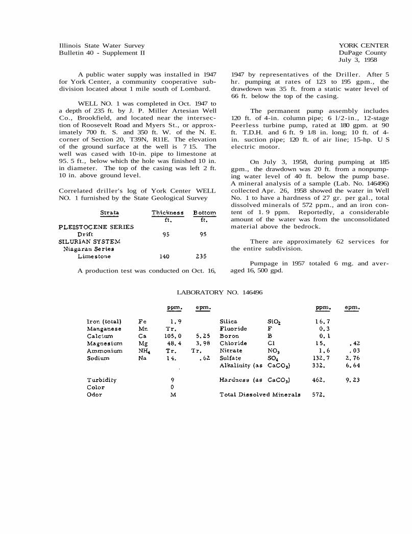
Illinois State Water Survey Bulletin 40 - Supplement II
A public water supply was installed in 1947 for York Center, a community cooperative sub-division located about 1 mile south of Lombard.
WELL NO. 1 was completed in Oct. 1947 to a depth of 235 ft. by J. P. Miller Artesian Well Co., Brookfield, and located near the intersec-tion of Roosevelt Road and Myers St., or approx-imately 700 ft. S. and 350 ft. W. of the N. E. corner of Section 20, T39N, R11E. The elevation of the ground surface at the well is 7 15. The well was cased with 10-in. pipe to limestone at 95. 5 ft., below which the hole was finished 10 in. in diameter. The top of the casing was left 2 ft. 10 in. above ground level.
Correlated driller's log of York Center WELL NO. 1 furnished by the State Geological Survey
A production test was conducted on Oct. 16,
YORK CENTER DuPage County July 3, 1958
1947 by representatives of the Driller. After 5 hr. pumping at rates of 123 to 195 gpm., the drawdown was 35 ft. from a static water level of 66 ft. below the top of the casing.
The permanent pump assembly includes 120 ft. of 4-in. column pipe; 6 l/2-in., 12-stage Peerless turbine pump, rated at 180 gpm. at 90 ft. T.D.H. and 6 ft. 9 1/8 in. long; 10 ft. of 4-in. suction pipe; 120 ft. of air line; 15-hp. U S electric motor.
On July 3, 1958, during pumping at 185 gpm., the drawdown was 20 ft. from a nonpump-ing water level of 40 ft. below the pump base. A mineral analysis of a sample (Lab. No. 146496) collected Apr. 26, 1958 showed the water in Well No. 1 to have a hardness of 27 gr. per gal., total dissolved minerals of 572 ppm., and an iron con-tent of 1. 9 ppm. Reportedly, a considerable amount of the water was from the unconsolidated material above the bedrock.
There are approximately 62 services for the entire subdivision.
Pumpage in 1957 totaled 6 mg. and aver-aged 16, 500 gpd.
LABORATORY NO. 146496

Illinois State Water Survey Bulletin 40 - Supplement II
Two wells are in service for the public water supply of the village of Yorkville (1568). The original supply from springs is maintained for emergency.
WELL NO. 1, described in Bulletin 40 as the well drilled in 1923, was equipped in Oct. 1951 with a new 12-stage Aurora turbine pump, rated at 100 gpm. An air line was installed 120 ft. long to the top of the bowls. The old 7 1/2-hp. electric motor was reinstalled.
Summary sample study log of WELL NO. 1 fur-nished by the State Geological Survey
The pump was pulled and rebuilt in June 1953.
WELL NO. 2 was completed in May 1954 to a depth of 42 ft. by Layne-Western Co., Aurora, and located at the site of Test Hole No. 2-54 near the southeast corner of the spring reser-voir, or approximately 2000 ft. N. and 1500 ft. E. of the S. W. corner of Section 4, T36N, R7E. The ground surface elevation at the well is 670. The well was double cased 38 in. by 12 in. and gravel packed with 12-in. pipe from 3 ft. above the ground surface to 18 ft. below; with 12-in. No. 5 stainless steel Layne shutter screen from 18 to 28 ft.; with 12-in. pipe from 28 to 37 ft.; and with 12-in. No. 5 stainless steel Layne shut-ter screen from 37 to 42 ft. A 38-in. od. No. 3 gage "Armco" iron casing was set from 2. 5 ft. above to 1. 75 ft. below the surface and the bore hole was finished 38 in. in diameter from top to bottom. The annulus between the 12-in. and 38-in. casings was packed with l/4 in. by 3/8 in. gravel.
A production test was conducted May 24-25, 1954 by representatives of the Driller, the State Water Survey, and Walter E. Deuchler Co., Consulting Engineers. After 16 hr. pump-ing at a rate of 203 gpm., the drawdown was 17. 9
YORKVILLE Kendall County March 10, 1958
ft. from a static water level of 2. 63 ft. below the top of the 12-in. casing (3 ft. above ground level). Ten min. after the pump was stopped, the water level had recovered to 6. 4 ft.
A 12 in. by 36 in. gravel pack well, 32 ft. deep including 10 ft. of screen, located 34 ft. west of the pumped well, was used for observing water levels during the test. At the end of the test the water level in the observation well had lowered 14. 4 ft. from a static level of 1. 3 ft. be-low the surface. Ten min. after the end of the test, the water level had risen 7. 7 ft.
A partial chemical analysis of a sample (Lab. No. 134922) collected May 25, 1954, after 16 hr. pumping at a rate of 203 gpm., showed the water in Test Hole No. 2-54 to have a hard-ness of 24. 6 gr. per gal., total dissolved min-erals of 530 ppm., and an iron content of 0.7 ppm.
The permanent pumping equipment in Well No. 2, finished at the site of Test Hole No. 2-54, consists of 30 ft. of 6-in. column pipe; 8-in., 4-stage Layne turbine pump (No. 27881), 3 ft. 8 in. in length; 7 ft. of 6-in. suction pipe; 32 ft. of air line; 10-hp. U S electric motor.
On Mar. 10, 1958, after 5 min. pumping at a rate of 165 gpm., the drawdown in Well No. 2 was 3 ft. from a nonpumping water level of 21 ft. below the pump base.
A mineral analysis of a sample (Lab. No. 145958) collected Mar. 10, 1958, after 5 min. pumping at a rate of 165 gpm., showed the water in Well No. 2 to have a hardness of 24.2 gr. per gal., total dissolved minerals of 488 ppm., and an iron content of 0.1 ppm.
Nonpumping water levels for Well No. 2 are shown in Table A.
TABLE A
Nonpumping Date water level
ft. 1956 July 19 Aug. 22 Sept. 23 Oct. 28 1957 July 18
Pumpage for the first 6 mo. of 1957 averaged 90,000 gpd.

2 - Yorkville
LABORATORY NO. 145958

Illinois State Water Survey Bulletin 40 - Supplement II
Since 1957 the city of Z.ion (11,941) has obtained its water supply from the Lake County Public Water District. Two of the city wells are maintained for stand-by use and the third well has been filled in and capped.
WELL NO. 1 is described in Bulletin 40. In Mar. 1954 a 10-in. liner was set from 307 to 376 ft. In Aug. 1955 nine new sections of column pipe were added making 370 ft. of column pipe; 32 ft. of suction pipe; 325 ft. of air line. In Sept. 1958 the pumping equipment included a Layne turbine pump and 60-hp. U S electric mo-tor.
Static water levels in Well No. 1 are shown in Table A.
WELL NO. 2, described in Bulletin 40, is
ZION Lake County January 28, 1960
now maintained for stand-by use.
WELL NO. 3, described in Bulletin 40, was filled in and capped early in 1958 by J. P. Miller Artesian Well Co., Brookfield.
During 1959 the city purchased an average of 570, 000 gpd. from the Water District.
TABLE A
Jan. 19, 1954 - static water level - 140 ft. Aug. 16, 1955 - static water level - 160 ft. Sept. 30, 1958 - static water level - 132 ft.
The static water level for Sept. 1958 was measured after the well had been put on stand-by basis.

Illinois State Water Survey Bulletin 40 - Supplement II
A public water supply was installed in 1932 for the Zurich Heights Subdivision, now known as the Zurich Heights Sanitary District (est. 350), located outside the west corporate limits of the village of Lake Zurich.
WELL NO. 1 was completed for Zurich Heights Subdivision about 1932 to a depth of 298 ft. by Otto Radke, Grays Lake, and located on Golf Road between Ravinia Ave. and Country Club Road at the extreme east end of the subdi-vision about 150 ft. west of U. S. Highway No. 12. The well was cased with 6-in. pipe to 298 ft. below ground level. The casing terminated in the bottom of a pit 6 ft. 5 in. below ground level. The pumping equipment included a 17-gpm. Deming plunger pump connected to a 3-hp. Wagner electric motor.
In 1956 this well was reportedly rehabili-tatedand restored to service by the Zurich Heights Sanitary District, consisting of residents in the Zurich Heights Subdivision.
A well was reportedly drilled for the Zurich
ZURICH HEIGHTS SANITARY DISTRICT Lake County February 10, 1959
Heights Sanitary District in 1947 to a depth of 276 ft. by Henry Boysen, Libertyville, and lo-cated 1425 ft. N. and 2250 ft. E. of the S. W. corner of Section 18, T43N, R10E. The well was deepened by Henry Boysen in 1951 to a depth of 300 ft. and cased with 6-in. pipe which termi-nated in the bottom of a pit 3 ft. below ground level.
The pumping equipment includes 160 ft. of ' 3-in. column pipe; Byron Jackson submersible pump rated at 100 gpm.; 160 ft. of air line; 10-hp. electric motor.
On June 5, 1958 the nonpumping water level was 128 ft.
A mineral analysis of a sample (Lab. No. 146914) collected June 5, 1958 from a tap in the storage tank showed the water in the well to have a hardness of 43 gr. per gal., total dissolved minerals of 1378 ppm., and an iron content of 0. 5 ppm.
There are 98 services, allmetered. Pump-age is estimated to average 20,000 gpd.
LABORATORY NO. 146914