additive manufacturing efforts and applications in expendable
TRANSCRIPT

Additive Manufacturing Efforts and Applications in Expendable Launch Vehicles
By:
Kyle A. Whitlow
05/01/2015

Kyle Whitlow AM Efforts and Applications in Expendable Launch Vehicles 1
Introduction
Expendable Launch Vehicles are single use space rockets used for lifting payloads into
space. The two primary expendable launch vehicle programs in use today are the Atlas V and
Delta IV launch vehicles. Both vehicles are designed, manufactured, and launched by ULA
headquartered in Centennial, Colorado. Both vehicles have a vast history dating back to the
1950s. This incredible history includes the launch of John Glenn, the first American to orbit the
earth, all American Mars rovers, and the vast majority of national security satellites [1]. Such
significant missions drive a very high standard of reliability. This high standard of reliability
often suppresses innovations that other industries experience as new technologies must be proven
repeatable and reliable to an extent that is not required of other industries. As a result of these
high standards, the Atlas V and Delta IV programs use a significant amount of outdated
technologies and processes. Advanced manufacturing methods such as Additive Manufacturing
promise to help modernize the technology used by the Atlas V and Delta IV launch vehicles
programs in an effort to significantly reduce cost, component lead times, processing and
assembly hours, and enable advanced analytical techniques. This paper reviews the approach
taken for utilization of Additive Manufacturing in the Atlas V and Delta IV expendable launch
vehicle programs.
Additive Manufacturing Applications in Expendable Launch Vehicles
There are three main areas where Additive Manufacturing is being implemented in the
Atlas V and Delta IV expendable launch vehicle programs: tooling, rapid prototyping, and both
polymer and metallic flight hardware.

Kyle Whitlow AM Efforts and Applications in Expendable Launch Vehicles 2
As expendable launch vehicles do require such high levels or repeatability and reliability,
the first logical application of Additive Manufacturing is tooling. Additive Manufacturing has
been used to produce tooling at ULA for several years now. Hundreds of tools have been printed
that have not only resulted in significant cost savings but have also significantly reduced
production cycle times. That is, the time in which it takes vehicle components to be
manufactured and assembled at the production facilities. Figure 1 shows example tools that have
been manufactured using the extrusion based process of Fused Deposition Modeling (FDM).
Figure 1: Example Additive Manufactured Tools
The figure shown above includes fastener drill templates, weld locating tools, destructive
spray-on insulation molds, avionics box geometric stay-out zones, and bracket locating
hardware. All tooling that is additive manufactured at ULA provides the production facilities one
of two benefits. Either the newly printed tool shows a great cost savings as the tool would have
otherwise been manufactured using more expensive, traditional methods or the tool is an enabler
as the tool would not have been created if Additive Manufacturing was not available. Both cases
represent a great benefit of Additive Manufacturing as it is applied to tooling.

Kyle Whitlow AM Efforts and Applications in Expendable Launch Vehicles 3
The second application of Additive Manufacturing at ULA is rapid prototyping. Rapid
prototyping allows for an abbreviated iterative design process flow for flight hardware. If an
error is discovered during manufacturing of a traditionally released design package, a large
amount of rework is required. Figure 2 represents the process flow of releasing a traditional
engineering package. Figure 3 represents the process flow of releasing an engineering package
using rapid-prototyping.
Figure 2: Traditional Engineering Process Flow
Figure 3: Engineering Process Flow using Rapid Prototyping
Through the use of rapid prototyping, additive manufacturing can identify design errors
far earlier in the process and can cut months from the development cycle. This is true whether or
not the end product is additively created. An important note is that related process innovations
that additive manufacturing enables such as model-based definition for components that the end
use product is additively created can even further reduce the engineering process flow.
Flight hardware is the most difficult and final application of Additive Manufacturing at
ULA. Extensive testing has been performed to fully characterize the polymer material and
process in order to qualify the material and process for flight use. Flight hardware is also the
application that has the most potential benefit as the Atlas V and Delta IV product lines are
expendable, meaning that new hardware is manufactured for each launch. During vehicle

Kyle Whitlow AM Efforts and Applications in Expendable Launch Vehicles 4
screenings that were performed in November of 2014, more than 150 additive candidates were
selected for both Atlas V and Delta IV. These were both metallic and polymer applications that
represented unique, complex geometries that drove expensive manufacturing methods.
Additional important considerations included part consolidation opportunities, critical lead time
reductions, potential to bring work in-house, and eliminating troublesome suppliers. Figure 4
shows a case study of a polymer additive manufactured flight assembly where Additive
Manufacturing enabled significant component-by-component cost savings, extensive part
consolidation, optimal conditioned air flow paths, and reduced weight when compared to the
heritage system.
Figure 4: Example Polymer Flight Component
Current Technology at ULA
ULA currently has three additive manufacturing systems as well as a significant number
of related technologies. All three systems use FDM technology. Figure 5 shows the current AM
systems and materials at ULA.

Kyle Whitlow AM Efforts and Applications in Expendable Launch Vehicles 5
Figure 5: Current Additive Manufacturing Systems at ULA
The Dimension machine is primarily used for rapid prototyping and small tooling
components. The two Fortus 900mc’s are used for rapid prototyping, tooling, material testing,
and flight hardware. ABS is a medium strength polymer used primarily for tooling. ABS – ESD7
is a modified form of ABS that is statically dissipative and used for avionics applications. One
benefit of ABS material is that it has support material that is dissolvable in Sodium Hydroxide
(NaOH). ULTEM 9085 is a high strength thermoplastic and is the material that ULA has fully
qualified for flight use. ULTEM 1010 is a slightly different type of ULTEM material that has
high better high-temperature characteristics. ULTEM 1010 would have great applications for
composite layup mandrels as this material can withstand the high temperatures of autoclaves.
Finally, ULA is pursuing a Nylon 12 material module as this material has exceptional elongation
and has dissolvable support material.

Kyle Whitlow AM Efforts and Applications in Expendable Launch Vehicles 6
ULA has a significant number of technologies that compliment the Additive
Manufacturing capabilities. These technologies include, but are not limited to: an ATOS Digital
Scanner to geometrically accept parts, a stereoscope, a 20 kip Instron tensile frame, a NaOH
dissolver tank, and a High-Speed Digital Imaging Correlation (HDIC) system as well as software
capabilities such as model-based definition and topology optimization. The digital scanner is
primarily used for geometric acceptance of parts by means of overlaying a point-cloud on the
nominal geometry to develop a contour plot of actual deviations from the nominal part geometry.
The stereoscope and tensile frame are used to test the raw and as-built material, respectively. The
NaOH tank is used to dissolve support material from components during post-processing and the
HDIC system is used to obtain comprehensive dynamic response data during static or high-speed
testing. Model-Based Definition eliminates dimensioning and drawing creations that are
unnecessary when using Additive Manufacturing. Finally, topology optimization is used to
design parts optimized for parameters such as strength, stiffness, and minimal weight.
FDM ULTEM 9085 Material and Process Qualification
ULTEM 9085 is the high strength polyetherimide thermoplastic that has been has been
fully characterized and qualified for flight use manufactured using FDM. The material and
process have been qualified through extensive testing. Appropriate processes have been
developed to control and ensure that the final production parts are acceptable for use in flight
applications.
The first testing performed was to define the specification controlled build parameters.
The Fortus pre-processing software has a number of build parameters that can be adjusted.
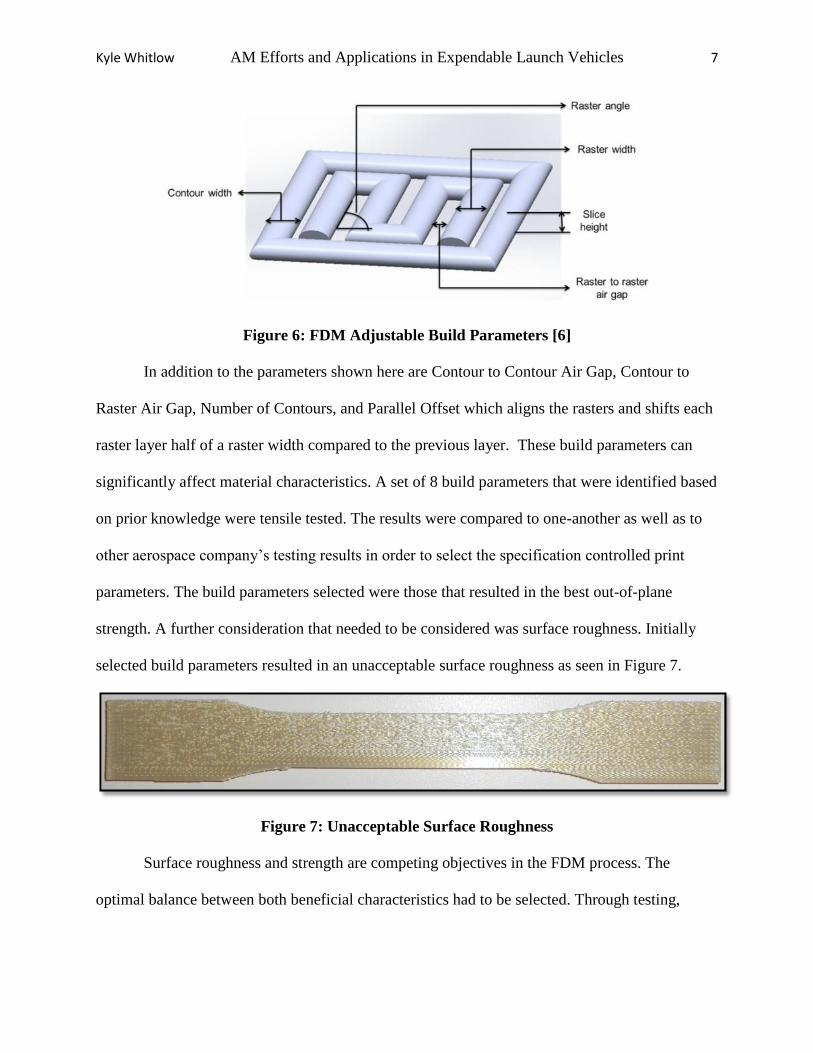
Figure 6 shows a visual representation of some of the build parameters that can are adjustable.
Kyle Whitlow AM Efforts and Applications in Expendable Launch Vehicles 7
Figure 6: FDM Adjustable Build Parameters [6]
In addition to the parameters shown here are Contour to Contour Air Gap, Contour to
Raster Air Gap, Number of Contours, and Parallel Offset which aligns the rasters and shifts each
raster layer half of a raster width compared to the previous layer. These build parameters can
significantly affect material characteristics. A set of 8 build parameters that were identified based
on prior knowledge were tensile tested. The results were compared to one-another as well as to
other aerospace company’s testing results in order to select the specification controlled print
parameters. The build parameters selected were those that resulted in the best out-of-plane
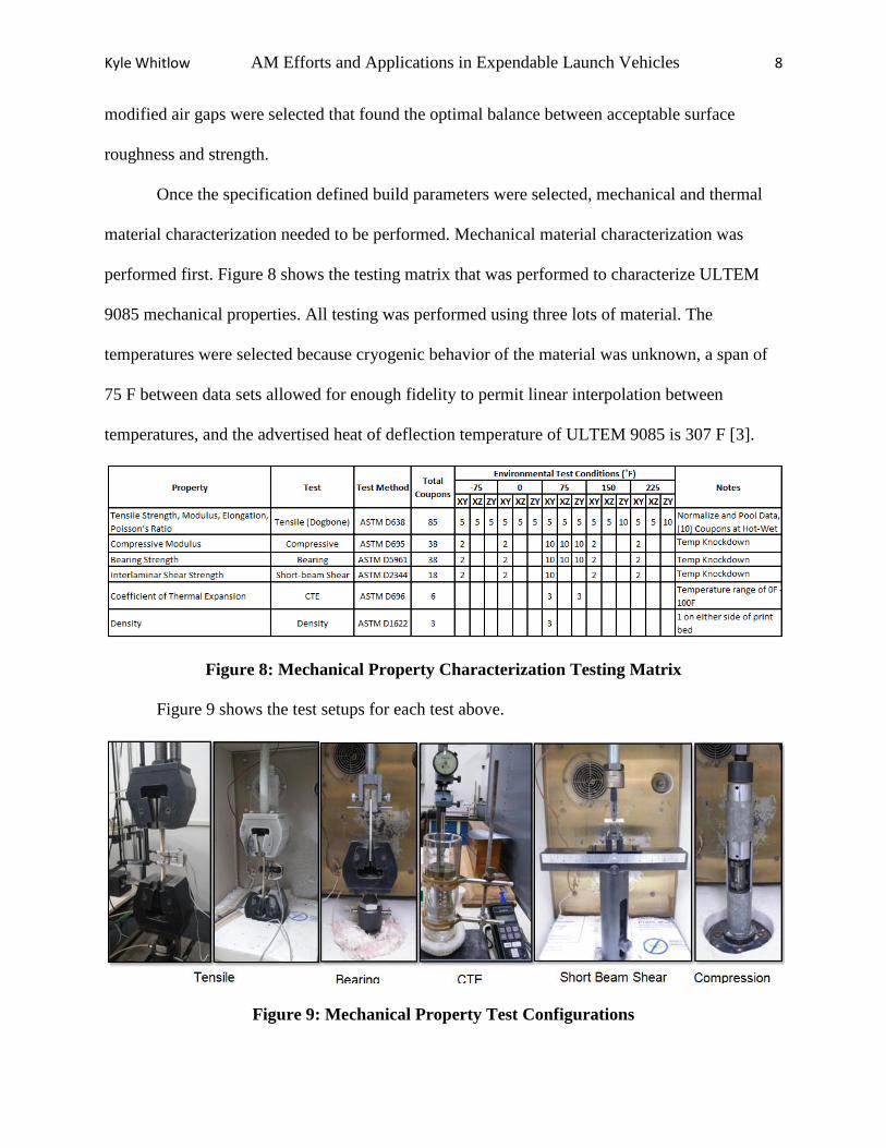
strength. A further consideration that needed to be considered was surface roughness. Initially
selected build parameters resulted in an unacceptable surface roughness as seen in Figure 7.
Figure 7: Unacceptable Surface Roughness
Surface roughness and strength are competing objectives in the FDM process. The
optimal balance between both beneficial characteristics had to be selected. Through testing,
Kyle Whitlow AM Efforts and Applications in Expendable Launch Vehicles 8
modified air gaps were selected that found the optimal balance between acceptable surface
roughness and strength.
Once the specification defined build parameters were selected, mechanical and thermal
material characterization needed to be performed. Mechanical material characterization was
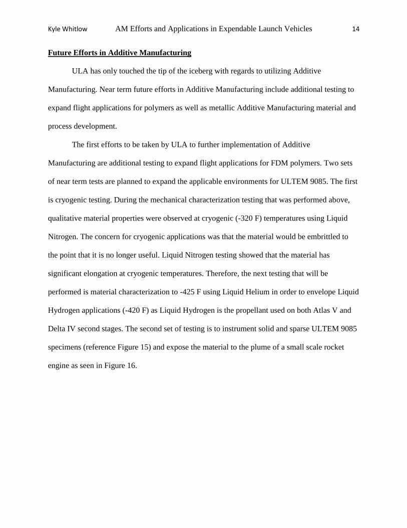
performed first. Figure 8 shows the testing matrix that was performed to characterize ULTEM
9085 mechanical properties. All testing was performed using three lots of material. The
temperatures were selected because cryogenic behavior of the material was unknown, a span of
75 F between data sets allowed for enough fidelity to permit linear interpolation between
temperatures, and the advertised heat of deflection temperature of ULTEM 9085 is 307 F [3].
Figure 8: Mechanical Property Characterization Testing Matrix
Figure 9 shows the test setups for each test above.
Figure 9: Mechanical Property Test Configurations

Kyle Whitlow AM Efforts and Applications in Expendable Launch Vehicles 9
The following testing was performed in addition to the mechanical testing shown above:
moisture conditioned tensile testing, moisture-freezing cycling, thermal vacuum testing, torque
definition testing, torque relaxation (compressive creep) testing, geometric shrink due to
differential cooling, and build volume thermal gradient effects testing.
All results were successfully obtained. This includes: all material properties, all MIL-
HDB-17 [2] derived A and B Basis strength allowables, all applicable knockdowns or weighting
factors dependent on moisture conditioning, temperature, orientation, and build location within
the build volume, torque definitions dependent on fastener size and type, and geometric shrink
factors.
The next step was to define all necessary thermal properties. Figure 10 shows the testing
matrix that was performed to characterize ULTEM 9085 thermal properties. All testing was
performed to the same lots of material and temperatures as the mechanical testing described
earlier.
Figure 10: Thermal Property Characterization Testing Matrix
Figure 11 shows the test setups for each test above.

Kyle Whitlow AM Efforts and Applications in Expendable Launch Vehicles 10
Figure 11: Thermal Property Test Configurations
All necessary thermal property values were successfully derived including the effects of
temperature and build orientation of the component on the respective thermal properties.
Additional testing that has been performed includes multiple vibration tests to show that
this material processed using FDM is not sensitive to a vibration environment. Vibration testing
has been successfully performed to +6 dB over flight environments to prove that the material’s
structural integrity is not sensitive to vibrations. Figure 12 shows the test configuration of one
such vibration tests.
Figure 12: Vibration Testing Test Configuration

Kyle Whitlow AM Efforts and Applications in Expendable Launch Vehicles 11
Successfully completing these vibration tests eliminates the need to vibration qualify or
proof test specific designs and allows for the use of static equivalent load factors in the strength
analysis of Additive Manufactured parts rather than complicated dynamic analyses.
The next steps in implementing FDM ULTEM 9085 for flight applications is sufficient
material and process control. Both material and process specifications have been released that
properly control both the raw material purchased for flight use as well as the process followed to
pre-process, manufacture, and post-process flight hardware. The material specification includes
lot traceability requirements, raw filament mechanical testing, and raw filament storage. The
process specification defines the build parameters, machine qualification process, machine
validation process, part finishing requirements, part geometric acceptance requirements, and part
integrity acceptance requirements.
All data derived from the testing described herein and the process utilized to manufacture
flight hardware was presented to the US Air Force, NASA, and Aerospace Corporation
customers on April 17, 2015. This presentation successfully approved FDM ULTEM 9085 for
flight use on Atlas, Delta, and next generation launch vehicles. This testing limits the material
applications to -75 to 225 F. Applications that fall outside of these temperature ranges must be
properly insulated until further testing approves the use of ULTEM 9085 beyond this
temperature range.
Training Efforts
One very important aspect of implementing Additive Manufacturing is properly training
the users of the technology. Training is currently being implemented that properly trains the
engineers that are to design and analyze Additive Manufactured hardware. Four important

Kyle Whitlow AM Efforts and Applications in Expendable Launch Vehicles 12
aspects of this training exist: when to use Additive Manufacturing, the Additive Manufacturing
process, how to best design and analyze for Additive Manufacturing, and all unique
considerations and lessons learned.
The first critical training topic is when to use Additive Manufacturing. One key idea
highlighted here is that Additive Manufacturing is a method of manufacturing intended to
supplement other manufacturing technologies. It is not a fix-all solution. As Figure 13 Shows,
Additive Manufacturing’s niche is parts that have a high level of geometric complexity and a
relatively low quantity of parts.
Figure 13: Training for Use of Additive Manufacturing [5]
The ULA Additive Manufacturing team feels that it is important for engineers that are
going to be using the technology to have a basic understanding of the process itself. Figures such
as Figure 14 are used to train the engineers as to how the FDM process works.

Kyle Whitlow AM Efforts and Applications in Expendable Launch Vehicles 13
Figure 14: FDM Process Diagram [6]
How to design and analyze for Additive Manufacturing is perhaps the most important
topic that an engineer using the technology must understand. Simply printing a component that is
designed for traditional manufacturing is like forcing a square peg through a round hole [4]. It is
forcing a technology on a design that was created for the limitations of traditional manufacturing.
It is critical that ULA not only teaches the engineers what the limitations of the technology are
but also to dream big in the sense that the part geometry can really be optimized in a way that
cannot be done using traditional manufacturing methods. Topology optimization is an advanced
analytical geometric optimization technique that the Additive Manufacturing training is to
include.
Finally, much has been learned about the FDM process and Additive Manufacturing in
general through the efforts that ULA has taken to implement Additive Manufacturing across the
enterprise. Lessons and best practices will continue to be learned as Additive Manufacturing is
further implemented across ULA. These lessons learned and best practices need to be properly
communicated to all engineers that will use this advanced manufacturing technology through the
training efforts described herein.
Kyle Whitlow AM Efforts and Applications in Expendable Launch Vehicles 14
Future Efforts in Additive Manufacturing
ULA has only touched the tip of the iceberg with regards to utilizing Additive
Manufacturing. Near term future efforts in Additive Manufacturing include additional testing to
expand flight applications for polymers as well as metallic Additive Manufacturing material and
process development.
The first efforts to be taken by ULA to further implementation of Additive
Manufacturing are additional testing to expand flight applications for FDM polymers. Two sets
of near term tests are planned to expand the applicable environments for ULTEM 9085. The first
is cryogenic testing. During the mechanical characterization testing that was performed above,
qualitative material properties were observed at cryogenic (-320 F) temperatures using Liquid
Nitrogen. The concern for cryogenic applications was that the material would be embrittled to
the point that it is no longer useful. Liquid Nitrogen testing showed that the material has
significant elongation at cryogenic temperatures. Therefore, the next testing that will be
performed is material characterization to -425 F using Liquid Helium in order to envelope Liquid
Hydrogen applications (-420 F) as Liquid Hydrogen is the propellant used on both Atlas V and
Delta IV second stages. The second set of testing is to instrument solid and sparse ULTEM 9085
specimens (reference Figure 15) and expose the material to the plume of a small scale rocket
engine as seen in Figure 16.

Kyle Whitlow AM Efforts and Applications in Expendable Launch Vehicles 15
Figure 15: Instrumented Ablative Test Specimens
Figure 16: Conceptual Test Setup for Material Ablative Properties
The ablative testing proposed will quantify the material’s heat, rate, and temperature of
ablation. Testing instrumented coupons printed with a sparse core will also provide a proof of
concept for a sacrificial, ablative layer separated from the structural aspect of the component by
means of a poor thermally conductive path. If this concept proves viable, it will eliminate the
need for thermal insulation on ULTEM 9085 hardware external to the vehicle that sees
temperatures in excess of 225 F due to aeroheating.
Following the completion of ULTEM 9085 testing, the next step in implementation of
polymer Additive Manufacturing is to qualify Nylon 12 material. The benefit of this material is
the very high elongations that the material can be subjected to as well as support material that is
dissolvable in NaOH. This allows for hardware to be designed that need not consider how
support material will be manually removed.

Kyle Whitlow AM Efforts and Applications in Expendable Launch Vehicles 16
In addition to the polymer materials testing and qualification, ULA is also pursuing the
purchase of a metallic Additive Manufacturing technology and later the qualification of the
metallic material and process for flight use. A trade study has been performed with assistance
from Oak Ridge National Laboratories and NASA Marshall Spaceflight Center that led to the
decision of purchasing a Concept Laser M1 powder bed system and dedicating this machine to
Inconel 718. In addition to considerations such as cost, lead time, build rate, build volume, and
in-situ quality tools, this decision was made largely on the fact that Marshall Spaceflight Center
is fully characterizing this material with the Concept Laser LaserCUSING technology and
making this information public in the NASA MAPTIS database. Partnering with Marshall
Spaceflight Center will allow for ULA to qualify the process and material for flight use on a very
condensed timeline.
Conclusion
Advanced manufacturing methods such as Additive Manufacturing promise to help
modernize the technology that the Atlas V and Delta IV launch vehicles programs use in an
effort to not only significantly reduce cost but also component lead times, processing and
assembly hours, and enable advanced analytical techniques. Although a significant amount of
effort has been performed to date, ULA has only touched the tip of the iceberg with respect to
implementation of Additive Manufacturing into the Atlas V and Delta IV expendable launch
vehicle programs.
Kyle Whitlow AM Efforts and Applications in Expendable Launch Vehicles 17
References:
[1] Butler, Amy. "A U.S. Air Force EELV Program Timeline." Aviation Week &
Space Technology (2015). Web. <aviationweek.com>.
[2] "Composite Materials Handbook." United States of America Department of
Defense MIL-HDBK-17 (2002). Print.
[3] "FortusUltem9085MaterialSpecSheet-US-1213." (2013). Web. <stratasys.com>.
[4] Grimm, Todd. "Focus on Manufacturing Using 3D Printing." Focus on
Fundamentals (2015). Print.
[5] Hayes, Michael. "Additive Manufacturing in Aerospace." Washington University
in St. Louis (2014). Print.
[6] Hossain, Mohammad, Jorge Ramos, David Espalin, Mireya Perez, and Ryan
Wicker. "Improving Tensile Mechanical Properties of FDM-Manufactured
Specimens via Modifying Build Parameters." University of Texas at El Paso
(2013). Web. <sffsymposium.engr.utexas.edu>.