additive manufacturing of silicon carbide-based … · national aeronautics and space...
TRANSCRIPT

National Aeronautics and Space Administration
www.nasa.gov
Additive Manufacturing of Silicon Carbide-Based
Ceramic Matrix Composites:
Technical Challenges and Opportunities
Mrityunjay Singh1, Michael C. Halbig2 and Joseph E. Grady2
1Ohio Aerospace Institute, Cleveland, OH2NASA Glenn Research Center, Cleveland, OH
https://ntrs.nasa.gov/search.jsp?R=20160010285 2018-07-15T23:50:10+00:00Z

National Aeronautics and Space Administration
www.nasa.gov
Outline
• Introduction and Background
• Technical Challenges
• Additive Manufacturing of SiC based Materials
• Laminated Object Manufacturing
• Binder Jet Printing
• Wood Containing Filaments for Preforms
• Powder Loaded Filaments/Paste Extrusion
• New Efforts
• NScrypt Machine
• Polymer composites for multi-functional applications
• Summary and Conclusions

National Aeronautics and Space Administration
www.nasa.gov
National Manufacturing Initiative and Role
of Additive Manufacturing Technologies
Major Policy Milestones
Frank Gayle, AMNPO, NIST
Major Initiatives

National Aeronautics and Space Administration
www.nasa.gov
Additive Manufacturing Technologies
2006
2010
Major Milestones
Various AM or RP
technologies were
developed in late
80’s and 90’s.
Copyright © 2016 Deloitte Development LLC. All rights reserved.

National Aeronautics and Space Administration
www.nasa.gov
Layers Have Been Used Differently Through
Cultures and Times… • Subtractive
– Material is successively removed from a solid
block until the desired shape is reached (2.5M
BC – Hominids)
• Fabricative– Elements or physical material are combined and
joined (6,000 BC – Western Asia)
• Formative– Mechanical forces and, or heat are applied to
material to form it into the desired shape such as
bending, casting and molding (3,000 BC –
Egyptians)
• Additive– Material is manipulated so that successive
pieces of it combine to make the desired object
(1984 – Californians)Dr Phil Reeves – lead consultant, Econolyst

National Aeronautics and Space Administration
www.nasa.gov
Potential Benefits of Additive Manufacturing
- Ease of Fabrication and Manufacturing
• Simplified formation matrix materials.
• Custom-made and complex geometries are possible which
were previously limited by traditional CMC processing
methods.
• Complex shapes involving the formation of curvatures and
sharp part transitions can be fabricated.
- Tailorable Composition and Properties
• Hybrid composites can be fabricated by the manipulation of
ceramic fiber preforms. Manual layer by layer assembly is time
consuming and expensive.
• Fabrication of composites with multifunctional properties.
- Lower Cost
• Reduced cost through fewer processing steps and short
production time from utilization of additive manufacturing.

National Aeronautics and Space Administration
www.nasa.gov
Conventional Manufacturing
• Customized parts in small volumes are time consuming and expensive to produce.
• Complex shape fabrication issues: mold design, dimensional tolerances, etc..
• Manufacturing of multifunctional parts are challenging.
Additive Manufacturing
▪ Small series of ceramic parts can be manufactured rapidly and cost-effectively.
▪ Specific molds are not required.
▪ Different designs can be optimized (no major cost of changes)
▪ Parts with significant geometric complexity.
Material and Process Challenges
▪ Property and behavior of starting materials
▪ Sintering and densification challenges
▪ Process modeling
▪ Mechanical behavior
▪ NDE and in-situ damage characterization
▪ Material and property databases
Efforts in the last >30 years have now
resulted in commercialized turbine engine applications.
Efforts in this very promising field are just now underway.
Materials and processing
challenges are quite similar
Additive Manufacturing of CMCs
Largest barrier to CMC insertion has been high acquisition cost
For AM, the starting materials are very low cost (powders and fibers)

National Aeronautics and Space Administration
www.nasa.gov
Overview of Additive Manufacturing Technologies(many variants and combinations)
NASA Aeronautics Research Mission Directorate FY12 LEARN Phase I Technical Seminar
Selective Laser Sintering
High powered laser fuses plastic, metal,
or ceramic powders by moving along
cross-sections repeating the process
upon the addition of powder.
Stereolithography
A beam of ultraviolet light is directed
onto a vat filled with a liquid ultraviolet
curable photopolymer and moves along
cross-sections of the object.
Fused Deposition Modeling
Plastic or metal is heated and supplied
through an extrusion nozzle and
deposited in a path determined by a
CAD model.
Binder Jet 3D Printing
An inkjet-like printing head moves
across a bed of powder and deposits
a liquid binding material in the shape
of the object’s cross section
Material choices are limited by the machine’s manufacturers
Fabrication of continuous fiber composites is not possible

National Aeronautics and Space Administration
www.nasa.gov
Current Approaches for Manufacturing of
Ceramic Matrix Composites
Melt Infiltration
(MI) Process
Preforming
and
Interface
Machining
(grinding, milling, drilling)
Polymer Infiltration/
Pyrolysis (PIP)
Process
Chemical Vapor
Infiltration (CVI) Process Hybrid Process
Joining
(brazing and attachments)
Coating and FinishingNDE
Post Processing and Nondestructive Evaluation
Hand lay-up and tooling of
ceramic fibers or woven shapes
A gas mixture is
infiltrated and SiC is
deposited into a fiber
preform.- Slow; large objects can
take weeks to months.
Preceramic polymer
infiltration and
pyrolysis to create a
SiC based matrix.- Multiple steps to
achieve matrix density
Slurry coated
prepregs or infiltration
of slurry/ resins into a
fiber preform.
- Infiltration of liquid
silicon to react with carbon to form SiC.
Combination of
CVI/PIP, CVI/MI,
or PIP/MI to
create a SiC
based matrix.- Several steps to
make a matrix

National Aeronautics and Space Administration
www.nasa.gov
Laminated Object Manufacturing of Ceramic Matrix
Composites (NASA LEARN Project by OAI)
• LOM is a viable option for manufacturing fiber reinforced
CMCs with modification to the machine.
• Issues with LOM machines manufacturing base.
Typical Process:
1. CAD design is turned into computer generated cross sections.
2. Layers of adhesive coated materials adhered to substrate with
heated roller.
3. Laser cuts cross-section of part.
4. Laser cross hatches non-part area.
5. Platform with completed layer moves down.
6. Fresh sheet moves over and platform
moves up. Layers are stacked to form the
shape with the desired thickness.
http://www.rpc.msoe.edu
New CMC prepreg material development
and characterization is a critical step

National Aeronautics and Space Administration
www.nasa.gov
Evaluation of Laser Cutting Parameters for
Silicon Carbide Fabrics and Prepregs
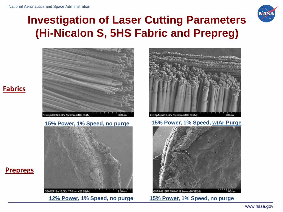
SEM specimens cut with different laser power/speeds
Prepregs for Composite Processing
• A number of SiC (Hi-Nicalon S, uncoated)
fabrics (~6”x6”) were prepregged.
• These prepregs were used for optimization
of laser cutting process.
• Baseline laser cutting data was also
generated for different types of SiC fabrics
(CG Nicalon, Hi-Nicalon, and Hi-Nicalon S)
Laser cut prepregs used for composite processing
Universal Laser System (Two 60 watt laser heads and a work area of 32”x18”)
National Aeronautics and Space Administration
www.nasa.gov
15% Power, 1% Speed, no purge 15% Power, 1% Speed, w/Ar Purge
Prepregs
12% Power, 1% Speed, no purge 15% Power, 1% Speed, no purge
Investigation of Laser Cutting Parameters
(Hi-Nicalon S, 5HS Fabric and Prepreg)
Fabrics
National Aeronautics and Space Administration
www.nasa.gov
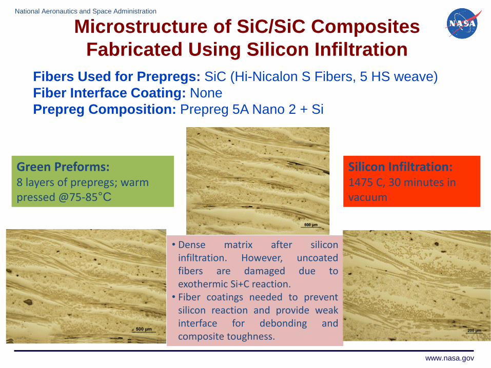
Microstructure of SiC/SiC Composites
Fabricated Using Silicon Infiltration
Fibers Used for Prepregs: SiC (Hi-Nicalon S Fibers, 5 HS weave)
Fiber Interface Coating: None
Prepreg Composition: Prepreg 5A Nano 2 + Si
• Dense matrix after siliconinfiltration. However, uncoatedfibers are damaged due toexothermic Si+C reaction.
• Fiber coatings needed to preventsilicon reaction and provide weakinterface for debonding andcomposite toughness.
Green Preforms: 8 layers of prepregs; warm pressed @75-85°C
Silicon Infiltration: 1475 C, 30 minutes in vacuum

National Aeronautics and Space Administration
www.nasa.gov
Microstructure of SiC/SiC Composites Fabricated Using Single Step Reaction Forming Process
Fibers Used for Prepregs: SiC (Hi-Nicalon S Fibers, 5 HS weave)
Fiber Coating: None
Prepreg Composition: Prepreg 5A Nano 2 + Si
Uncoated SiC fibersshow no visible damagedue to Si exothermicreaction.
Green Preforms: 8 layers of prepregs; warm pressed @75-85°C
Heat Treatment: 1475°C, 30 minutes in vacuum
Micrographs show gooddistribution of SiC andSi phases.
National Aeronautics and Space Administration
www.nasa.gov
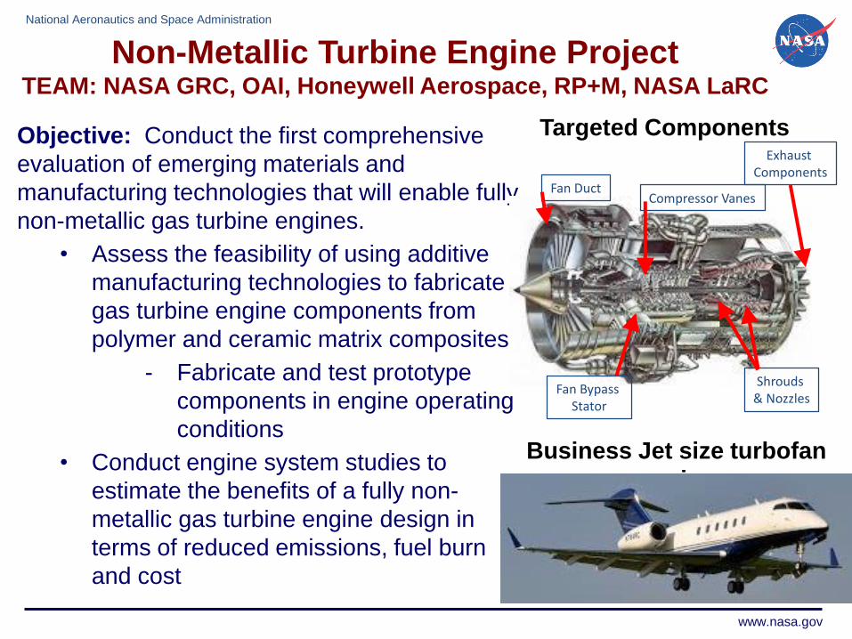
Objective: Conduct the first comprehensive
evaluation of emerging materials and
manufacturing technologies that will enable fully
non-metallic gas turbine engines.
• Assess the feasibility of using additive
manufacturing technologies to fabricate
gas turbine engine components from
polymer and ceramic matrix composites.
- Fabricate and test prototype
components in engine operating
conditions
• Conduct engine system studies to
estimate the benefits of a fully non-
metallic gas turbine engine design in
terms of reduced emissions, fuel burn
and cost
Fan Duct
Shrouds & Nozzles
Fan Bypass Stator
Compressor Vanes
Exhaust Components
Business Jet size turbofan
engine
Targeted Components
Non-Metallic Turbine Engine ProjectTEAM: NASA GRC, OAI, Honeywell Aerospace, RP+M, NASA LaRC

National Aeronautics and Space Administration
www.nasa.gov
Additive Manufacturing of Ceramics
using Binder Jet Printing Technologies
Binder Jet printing
An inkjet-like printing head moves across a bed of powder and deposits
a liquid binding material in the shape of the object’s cross section
Binder jet printing capability will allow for
powder bed processing with tailored binders and chopped
fiber reinforcements for advanced ceramics.
In Collaboration with rp+m
ExOne’s M-Flex print machine

National Aeronautics and Space Administration
www.nasa.gov
Processing
- Constituents
• SiC powders: Carborex 220, 240, 360, and 600 powders
(median grain sizes of 53, 45, 23, and 9 microns
respectively). Used solely and in powder blends
• Infiltrants: SMP-10 (polycarbosilane), SiC powder loaded
SMP-10, phenolic (C, Si, SiC powder loaded), pure silicon
• Fiber reinforcement: Si-TUFF SiC fiber; 7 micron mean
diameter x 65-70 micron mean length, 350 GPa Modulus
• Optimization of powder spreading and bimodal
distributions of powders is critical
Microstructure
- Optical microscopy
- Scanning electron microscopy
Properties
- Material density (as-manufactured and after infiltration steps)
- Mechanical properties: 4-point bend tests
Approach for Additive Manufacturing of CMCs
Si-TUFF SiC fibers (Advanced Composite
Materials, LLC)
Constituents
SiC powder loaded SMP-10
SiC powder
SiCpowder
Phenolic infiltrant
SiC powder
SiC powder
Processing, microstructure, and property correlations provide
an iterative process for improving the CMC materials.

National Aeronautics and Space Administration
www.nasa.gov
Microstructure of Silicon Carbide Preforms
Carborex 240 SiC Powders with
SMP-10 Infiltration
Carborex 360 SiC Powders with
SMP-10 Infiltration

National Aeronautics and Space Administration
www.nasa.gov
Different views of are shown of a
CMC coupon with 35 vol% SiC fiber
loading and infiltrant with smaller
SiC powders.
- Higher density observed due to
powder loaded infiltrant
- Good distribution and non-
preferred orientation of SiC fibers
is observed.
SiC FiberSiC
Powder
InfiltrantSiC
Powder
SiC FiberSiCPowder
SiCPowder
Infiltrant
SiCPowder
SiCPowder
SiC Fiber
Fabrication and Microstructure of SiC Fiber
Reinforced CMCs

National Aeronautics and Space Administration
www.nasa.gov
Mechanical Properties of SiC and CMC
Materials at RT and 1200°C
20
0
10
20
30
40
50
0.000 0.020 0.040 0.060 0.080
Str
ess (
MP
a)
Strain (%)
Non-Reinforced SiC - Set G
1.40
1.50
1.60
1.70
1.80
1.90
2.00
2.10
2.20
Den
sity
(g
/cc)
Density at as-processed through 1, 2, and 3 infiltrations
I5
N5
O5
G5
P6
Q6
0 321
0
10
20
30
40
50
60
70
80
0.000 0.020 0.040 0.060 0.080 0.100
Str
ess (
MP
a)
Strain (%)
65 vol. % SiC Fiber Reinforced SiC - Set N
The fiber loaded SiC
materials had significantly
higher stresses and higher
strains to failure.

National Aeronautics and Space Administration
www.nasa.gov
Demonstration of the Additive Manufacturing of
Turbine Engine CMC Components (20 vol.% SiC Fiber)
High pressure turbine nozzle segments: cooled doublet vane sections.
First stage nozzle segments.

National Aeronautics and Space Administration
www.nasa.gov22
Additive Manufacturing of Ceramics using
3-D Printing Technologies
These printers can print polymers with specific filaments
Ability to fabricate ceramics is being investigated
MakerBot Replicator 2XOrion Delta 3D Printer
Rostock 3D Printer
Develop and characterize feed materials for 3-D printing of silicon
carbide (SiC)-based ceramics.3-D Printing Efforts
• Powder Loaded Filament - direct printing of ceramic parts
• Wood Containing Filament - provide preforms for densification
• Slurry Dispensing of Pastes - evaluate pastes for full conversion to dense SiC

National Aeronautics and Space Administration
www.nasa.gov
3-D Printing: Powder Loaded Filament
• Green SiC ceramic filament was extruded for the 3-D printing.
National Aeronautics and Space Administration
www.nasa.gov
3-D Printed Sample
23

National Aeronautics and Space Administration
www.nasa.gov
3-D printed porous
disc
Dip-coated in Polycarbosilane(PCS) solution
Heat treated at 400°C in
argon
Dip-coated in
PCS solution
Exposed to 1000°C in argon
Pyrolyzed at 1450°C
in vacuum
3-D Printing: Wood Containing Filament Parts
for Ceramic Preforms and Conversion
A 3-d printed disc is made using a commercially available wood filament.
Printed part is pyrolyzed to serve as a preform.
Procedure:
National Aeronautics and Space Administration
50%wt. Retention
35%wt. Retention

National Aeronautics and Space Administration
www.nasa.gov
Wood Containing Filament –
PCS/SiC then PCS –1450°C
National Aeronautics and Space Administration
www.nasa.gov

National Aeronautics and Space Administration
www.nasa.gov
3-D Printing: Slurry Dispensing of Pastes
Orion Delta 3D Printer
National Aeronautics and Space Administration
www.nasa.gov
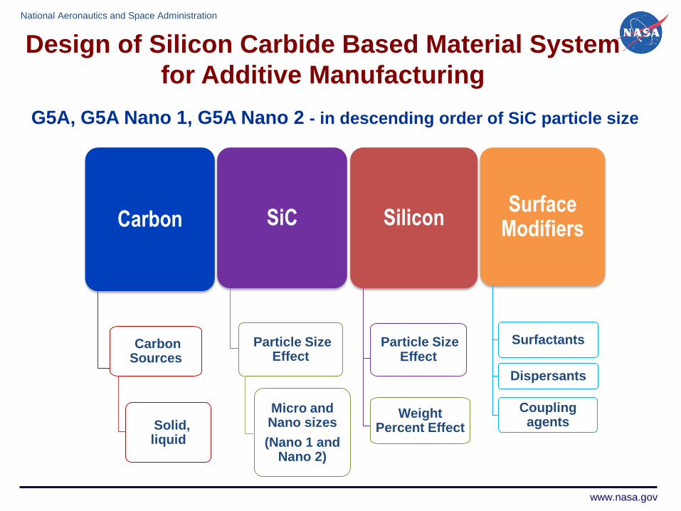
G5A, G5A Nano 1, G5A Nano 2 - in descending order of SiC particle size
Carbon
Carbon Sources
Solid, liquid
SiC
Particle Size Effect
Micro and Nano sizes
(Nano 1 and Nano 2)
Silicon
Particle Size Effect
Surface Modifiers
Surfactants
Dispersants
Coupling agents
Design of Silicon Carbide Based Material System
for Additive Manufacturing
Weight Percent Effect

National Aeronautics and Space Administration
www.nasa.gov
Weight Retention of Pre-Ceramic Pastes
Weight retention values are promising for all samples secondary infiltration steps may not be necessary
Weight loss trends found in furnace weight loss studies similar to TGA data
0
10
20
30
40
50
60
70
80
90
100
1200°C Low Vacuum 1350°C Low Vacuum 1450°C Low Vacuum 1450°C High Vacuum
Per
cen
t M
ass
Ret
ain
ed
Pyrolysis Conditions
G5A G5A Nano 1 G5A Nano 2G5A 10 wt% G5A Nano 1 10 wt% Si G5A Nano 2 10 wt% SiG5A 20 wt% Si G5A Nano 1 20 wt% Si G5A Nano 2 20 wt% Si

National Aeronautics and Space Administration
www.nasa.gov
• All compositions after pyrolysis show a high yield of SiC.
• Vaporization of Si occurs in vacuum due to its high vapor pressure.
0
20
40
60
80
100
Silicon Carbide Silicon Carbon
Wei
gh
t P
erce
nta
ge
Chemical Compound
G5A 10 wt% Si G5A Nano 1 10 wt% Si G5A Nano 2 10 wt% Si
G5A 20 wt% G5A Nano 1 20 wt% G5A Nano 2 20 wt%
G5A 30 wt% Si G5A Nano 1 30 wt% Si G5A Nano 2 30 wt % Si
0102030405060708090
100
Silicon Carbide Silicon Carbon
Wei
gh
t P
erce
nta
ge
Chemical Compound
Low Vacuum
(10-2 Torr)
High Vacuum
(10-5 – 10-6 Torr)
Without
extra Si
Chemical Composition of Heat-treated Pastes at 1450°C
(from X-Ray Diffraction Analysis)

National Aeronautics and Space Administration
www.nasa.gov
Additive Manufacturing of Electric Motors (Ultra-Efficient Commercial Vehicles and Transition to
Low Carbon Propulsion)
NScrypt 3D Printer
Micro Dispense Pump 3D Direct Printing
Systems
•Ability to host up to four separate materials
and print on curved surfaces or print 3D
structures.
•Motion control accuracy of ±5 microns and
repeatability of ±2 microns in XY Micro-
dispensing pump has volume control of
dispensed materials of 100 picoliters.
•Ability to print a wide variety of ceramic
pastes (structural and functional), electronic
pastes, adhesives, solders, bio-materials.

National Aeronautics and Space Administration
www.nasa.gov
Additive Manufacturing of Polymer
Composites for Multifunctional Applications
Microstructures and coupon properties being evaluated• Color Fab, bronze fill metal, PLA • Color Fab, copper fill metal, PLA • GMASS, Tungsten, ABS • GMASS, Bismuth, ABS• Proto Pasta, Magnetic iron, PLA • Proto Pasta, Stainless Steel, PLA• 3DXTech, premium red, ABS • 3DXTech, black, ABS• 3DXNano ESD (CNT) black, ABS • Carbon Fiber 5 wt%, ABS• Homemade ABS, (200C) • wood containing filament• SeeMeCNC ABS natural • iglidur, l180-PF Tribo Filament
Potential Missions/Benefits:• On demand fabrication of as needed functional components in
space (ISS, in-orbit manufacturing)
• Tailored, high strength, lightweight support structures that are
reinforced with CNT for lightweight multifunctional aerospace
structures (e.g., thermal management with structural capability,
solar panels with structural capability, habitat structures)
• Tailored facesheets for functional properties, i.e. wear resistance,
vibration dampening, radiation shielding, acoustic attenuation,
thermal management

National Aeronautics and Space Administration
www.nasa.gov
Color Fab, copper fill metal, PLA
Proto Pasta, Magnetic iron, PLA
3-D Printing of Multi-Functional Materials
GMASS, Tungsten,
ABS
GMASS, Bismuth, ABS
0.1 mm
0.4 mm
Highest strength and modulus in CNT reinforced coupons
Pure ABS Coupons – less porosity for lower print heights

National Aeronautics and Space Administration
www.nasa.gov
Summary and Conclusions
• Additive manufacturing can offer significant
advantages in fabricating preforms, ceramics
and CMCs.
• They will have to be selectively applied to
“traditional” components but can also enable
new applications.
• Good progress is occurring in binder jet
printing and LOM.
• AM and 3-D printing of ceramics has the
potential to be game changing.
33
National Aeronautics and Space Administration
www.nasa.gov
Acknowledgements
• The LOM effort was supported by NASA funded
LEARN Phase I award at OAI.
• The binder jet effort was supported by a NASA
Aeronautics Research Institute (NARI) project.
• The authors would like to thank personnel at rp+m
for their collaborative efforts in binder jet printing.
• The authors would like to thank summer students,
Shirley Zhu, Anton Salem, Lily Kuentz, and
laboratory support staff.
34