additive systems inc. since 1984 hammer injection block
TRANSCRIPT
ADDITIVE SYSTEMS INC.407 S. Main St • Broken Arrow OK, 74012
www.additivesystems.com 1-800-324-1420
“Since 1984”
Hammer Injection BlockInstallation & Operation Manual
ADDITIVE SYSTEMS INC.Since 1984
®
Rev 21
*Disassembly of ASI Hammer Injection Block Voids Warranty*
2 Copyright 2020 www.additivesystems.com 1-800-324-1420
AD
DIT
IVE
SY
ST
EM
SIN
C.
“Sin
ce 1
984”
Hammer Injection Block®
STANDARD FEATURES
• Stainless steel machined manifold block.• 3/8” FNPT inlet and outlet connections machined into block.• Oval gear meter machined into manifold block.• High resolution gears 5200 pulses per gallon output.• Meter accuracy of 0.5%.• Meter repeatability 0.25%.• Oval Gear material 316 Stainless Steel.• Gear pinion shafts of Carbide tool steel.• Explosion proof Hall-Effect meter sensor.• Sensor is 3-wire type with power (12VDC), common, and pulse signal connections.• 3/8” FNPT Calibration port with standard quick disconnect coupler.• Built-in strainer• Built-in check valve• Inlet and outlet isolation and throttling valves.• ASCO® Solenoid 120 VAC (120/60hz , 110/50hz)**
• Solenoid is UL or Cenelec Class I, Div I machined into manifold block.
• Max 400 PSI working pressure.• Max 150 PSI differential pressure.• Solenoid Chemraz seat standard.• ** Option: ASCO® Solenoid 240 VAC (240/60hz , 220/50hz)
Optional Accessories
• Calibration kit, including quick-coupler (female), cylinder, back pressure check valve, and spout. (ASI HB-200)• New and improved calibration port quick-coupler (male). (ASI HB-109)• Inlet and outlet isolation/flow control locking needle valves. (ASI HB-101)• Inlet strainer (100 Mesh). (Call to order)• Inlet manifolds for 2-pak thru 8-pak. (Call to order)
• Up to 8 slave hammer injection blocks can be mounted, pumbed and wired for A/C + D/C on mounting back board.
*See Page 14 for complete list of spare parts & accessories.

3Copyright 2020 www.additivesystems.com 1-800-324-1420
AD
DIT
IVE
SY
ST
EM
SIN
C.
“Sin
ce 1
984”
Hammer Injection Block®
FUNCTIONAL DESCRIPTION
The ASI Hammer Injection Block manifold is a low cost solution to chemical additive injection in the petroleum terminal environ-ment. This manifold design meets all of the normal requirement for metering and control of a cyclical injection chemical stream. The ASI Hammer Injection Block provides an electrically operated solenoid valve and a precision fluid meter in a common manifold. In addition, the manifold includes inlet and outlet isolation valves, an inlet strainer, and an outlet check valve. Combining this func-tionality into a single monolithic manifold block reduces the size of the instrumentation. This is critical in the limited spaces available on truck loading racks today. Additionally, combining the solenoid, meter, and test port into a single manifold eliminates most potential leak points common to stick built manifolds assembled in the field.
This manifold block provides the physical instrument needed to allow a Terminal Automation System, Preset, or PLC System to directly control chemical additive injection. This manifold does not include the electronics control necessary to pace the chemical to a flowing fuel stream, nor does it contain the logic necessary to accumulate additive volume passing through it.
AC line voltage is typically used to energize the solenoid valve and allow flow. The controlling device then accumulates flow volume in the form of pulses transmitted from the meter sensor. When sufficient volume of additive chemical has moved through the manifold, the controlling device then turns off the solenoid valve in order to stop flow. It is the responsibility of the controlling device, Terminal Automation System, Preset, or PLC System, to perform the algorithms necessary to ratio the chemical properly into the fuel stream. Functionality for recipe, injection interval, tolerance, alarm annunciation, shutdown, etc. all are the responsibility of the controlling system. If the controlling system is not capable of this level of function, manifold blocks alone are not the solution. The user should consult our factory for information on complete injec-tion panels that include microprocessor based controllers having the capability of complete injection control.
4 Copyright 2020 www.additivesystems.com 1-800-324-1420
AD
DIT
IVE
SY
ST
EM
SIN
C.
“Sin
ce 1
984”
Hammer Injection Block®
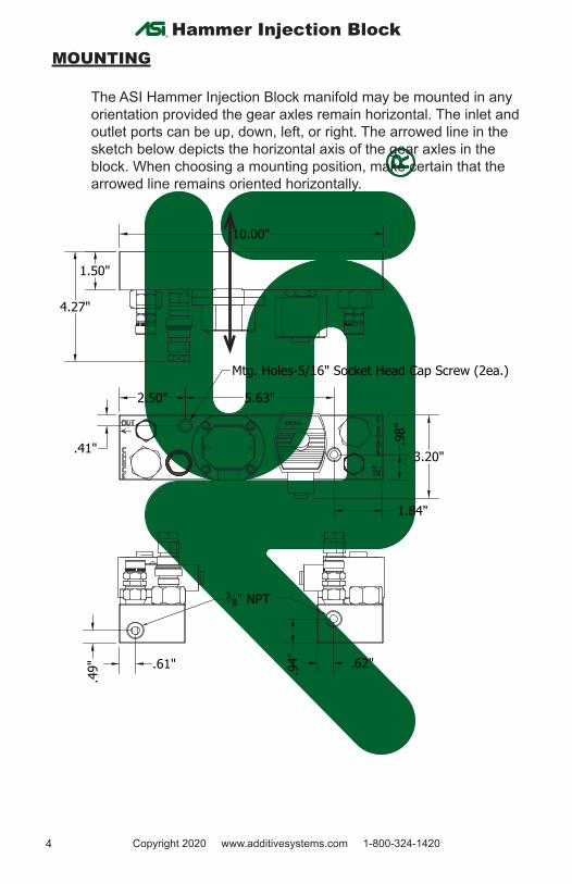
MOUNTING
The ASI Hammer Injection Block manifold may be mounted in any orientation provided the gear axles remain horizontal. The inlet and outlet ports can be up, down, left, or right. The arrowed line in the sketch below depicts the horizontal axis of the gear axles in the block. When choosing a mounting position, make certain that the arrowed line remains oriented horizontally.
10.00"
1.50"
4.27"
3.20"
2.50"
1.84"
5.63"
.41" .98"
Mtg. Holes-5/16" Socket Head Cap Screw (2ea.)
.62".94".61"
.49"
38" NPT
5Copyright 2020 www.additivesystems.com 1-800-324-1420
AD
DIT
IVE
SY
ST
EM
SIN
C.
“Sin
ce 1
984”
Hammer Injection Block®
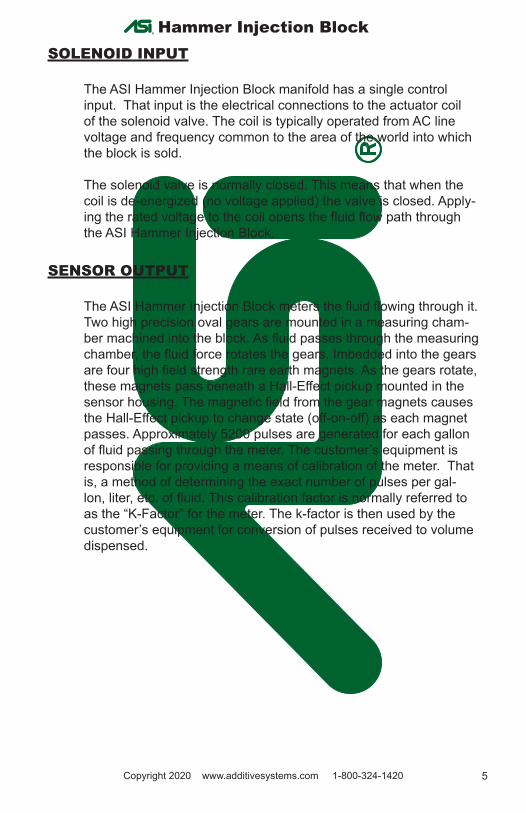
SOLENOID INPUT
The ASI Hammer Injection Block manifold has a single control input. That input is the electrical connections to the actuator coil of the solenoid valve. The coil is typically operated from AC line voltage and frequency common to the area of the world into which the block is sold.
The solenoid valve is normally closed. This means that when the coil is de-energized (no voltage applied) the valve is closed. Apply-ing the rated voltage to the coil opens the fluid flow path through the ASI Hammer Injection Block.
SENSOR OUTPUT
The ASI Hammer Injection Block meters the fluid flowing through it. Two high precision oval gears are mounted in a measuring cham-ber machined into the block. As fluid passes through the measuring chamber, the fluid force rotates the gears. Imbedded into the gears are four high field strength rare earth magnets. As the gears rotate, these magnets pass beneath a Hall-Effect pickup mounted in the sensor housing. The magnetic field from the gear magnets causes the Hall-Effect pickup to change state (off-on-off) as each magnet passes. Approximately 5200 pulses are generated for each gallon of fluid passing through the meter. The customer’s equipment is responsible for providing a means of calibration of the meter. That is, a method of determining the exact number of pulses per gal-lon, liter, etc. of fluid. This calibration factor is normally referred to as the “K-Factor” for the meter. The k-factor is then used by the customer’s equipment for conversion of pulses received to volume dispensed.
6 Copyright 2020 www.additivesystems.com 1-800-324-1420
AD
DIT
IVE
SY
ST
EM
SIN
C.
“Sin
ce 1
984”
Hammer Injection Block®
WIRING
SolenoidThe solenoid wiring should be a minimum of #16 AWG, type THHN or THWN wire. Good practice dictates AC and DC wiring should be ran in separate conduits for extended distances. Follow local, state, and federal codes and practices applicable to your area.
WARNING: The solenoid coil presents an inductive load to the switching device controlling it. High counter EMF volt-ages may be produced when removing the voltage source from such loads. Steps should be taken to ensure these high surge voltages are properly dissipated or equipment damage to the controlling device may occur. Consult with the manufacturer of the controlling equipment for guidance regarding the control of inductive loads. Triac switching is recommended
Meter Sensor (general)The sensor wiring can be three conductor, #18-22 AWG shielded instrument cable, with a foil or braided wire shield. Use Belden® number 9363 or similar. Drain or shield wires should be terminated on a DC COMMON or on a specifically assigned shield termination at the controller end only. Do not terminate shields to AC earth ground. Tape off and isolate the shield at the sensor end. Refer to wiring diagrams in this document for specific connection details.
Meter Sensor - Pulse Signal OutputThe ASI Hammer Injection Block meter sensor output is an un-sourced, open collector, transistor output. The blue sensor wire is connected to the transistor collector. The emitter of the transistor is connected to the black wire, or DC COMMON connection. The term “un-sourced” means that no voltage is applied to the output from within the sensor. It must be pulled to a ‘high’ or ‘on’ or ‘true’ state by voltage supplied from an external source. The sensor electronics then drives the collector ‘low’ or ‘off’ or ‘false’ with each pulse transmitted. The output is NOT driven high internally within the sensor. This industry common scheme allows the sensor to drive external equipment supplied by its own internal transmitter power. There must be a common connection between the DC negative of the sensor supply and the DC COMMON of the signal accumulating device. Refer to the wiring diagrams at the end of this manual for specific connection details.
7Copyright 2020 www.additivesystems.com 1-800-324-1420
AD
DIT
IVE
SY
ST
EM
SIN
C.
“Sin
ce 1
984”
Hammer Injection Block®
Customer Equipment for Meter Sensor InputThe controlling equipment used for capturing pulses from the ASI Hammer Injection Block may be of two general categories; Un-sourced Inputs, having no voltage present normally on the input connection; Sourced Inputs, having a DC pull-up voltage supplied to the input connection. Two different wiring methods are used for the two types of pulse inputs. Wiring diagrams are provided at the end of this document for each type of input. Refer to the documen-tation for the controlling equipment for a description of the inputs to determine the type. If the documentation still does not resolve the issue, the following test can be performed.
A digital volt-ohm meter is used to test the equipment input for the presence of voltage. Place the meter in the DC Voltage mode. Disconnect any wires on the DC Pulse Input. Power the control-ler. Measure the voltage from the DC COMMON terminal (black voltmeter lead) to the DC Pulse Input (red voltmeter lead). If the voltage reading is greater than +5.0 volts, the input is considered a sourced input. If the voltage reading is less than +5.0 volts, the input is considered an un- sourced input. Refer to the correspond-ing wiring diagram for connections.
Test setup for determining customer equipment input type.> +5.0 Volts = Sourced Input< +5.0 Volts = Un-sourced Input
8 Copyright 2020 www.additivesystems.com 1-800-324-1420
AD
DIT
IVE
SY
ST
EM
SIN
C.
“Sin
ce 1
984”
Hammer Injection Block®
FLUID CONNECTIONS
The fluid inlet and outlet of the ASI Hammer Injection Block mani-fold is marked with engraved text on the block. The inlet pressure should always be higher than the outlet pressure to ensure proper operation.
Fluid Inlet PipingAttention should be given to flow dynamics when sizing the tubing, isolation valve, and strainer components feeding the injector inlet. The minimum tubing size for the ASI Hammer Injection Block is ½”. Significantly lower flow rates may allow smaller tubing dimensions. Tubing ID should always be smaller than the OD. The isolation valve and strainer size must be increased to handle the flow re-quired for the number of blocks being fed.
Fluid Outlet PipingStainless steel tubing is also used for piping the outlet of the ASI Hammer Injection Block manifold to the point of injection.
WARNING: A check valve and an isolation valve MUST be installed between the manifold and the point of injection! Failure to install an isolation valve will require complete fuel delivery system shutdown in the event of a need for service on the injector manifold. Failure to install a check valve in the line may result in fuel backing up into the additive chem-ical delivery system and may cause contamination or spill.
Good design practice dictates that an isolation valve, usually a quarter turn ball valve, be installed at the point of chemical injec-tion into the fuel piping. This valve should meet the needs of local policies and practices regarding piping system valves.
An injection point check valve is required. This check valve should be a positive shutoff, spring closed check such as a plug or ball type. A small opening or ‘cracking’ pressure is acceptable, gener-ally limited to a maximum of 15 PSI. Cracking pressures of 1 PSI and 10 PSI are common in the industry. Ensure the flow character-istic ( Cv ) of the check valve is adequate to handle the maximum flow rate expected through the injector manifold. Although the lo-cation is not critical, it is common practice to place the check valve near the isolation valve at the point of injection.
9Copyright 2020 www.additivesystems.com 1-800-324-1420
AD
DIT
IVE
SY
ST
EM
SIN
C.
“Sin
ce 1
984”
Hammer Injection Block®
Remember, pressure differentials across the isolation valve, check valve, tubing, manifold, strainer, etc. all accumulate and ultimately dictate the required supply pump pressure. Minimizing the individ-ual pressure drops allow the lowering of the supply pump pressure and effectively reduces the load and wear on the system.
WARNING: Care should be exercised when connecting multiple injector manifold blocks to one common point of injection. Each manifold line MUST have its own check valve to ensure against cross contamination. The length of common piping should be minimized to ensure all additive chemical being injected reaches the fuel line. Not all chem-icals are compatible. If multiple additives are used simulta-neously, be certain to size common piping for the combined flow.
Thermal Expansion ReliefThermal relief bypass kits are required with the ASI Hammer Injec-tion Block manifold when installed with a point-of- injection actu-ated valve. This includes a solenoid valve or electric or pneumatic actuated ball valve.
The ASI Hammer Injection Block manifold will stop flow in the re-verse direction when the solenoid is de-energized. The check valve in the block prevents reverse flow. When the additive chemical injection system is idle, any fluid expansion that occurs between the block and the point of injection MUST be relieved, usually back to additive storage. When designing the pumping system, provision should be made to allow this thermal expansion volume to return to the additive chemical storage tank.
10 Copyright 2020 www.additivesystems.com 1-800-324-1420
AD
DIT
IVE
SY
ST
EM
SIN
C.
“Sin
ce 1
984”
Hammer Injection Block®
SPECIFICATIONS
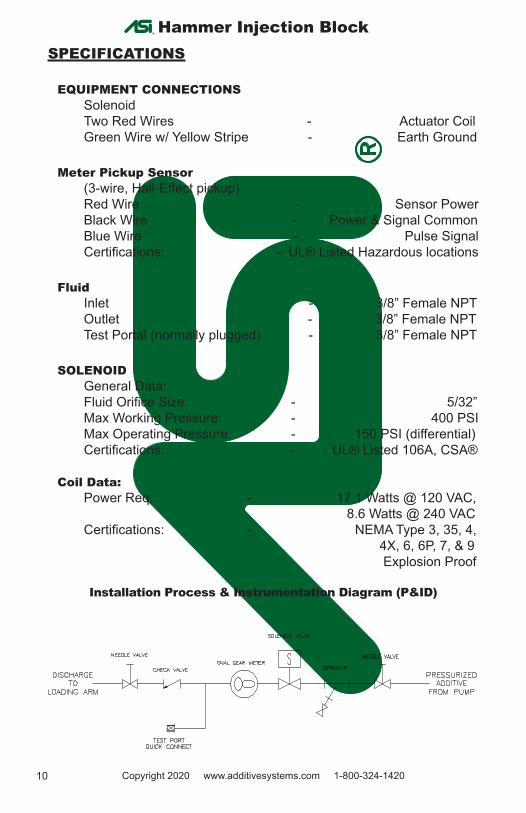
EQUIPMENT CONNECTIONSSolenoidTwo Red Wires - Actuator CoilGreen Wire w/ Yellow Stripe - Earth Ground
Meter Pickup Sensor(3-wire, Hall-Effect pickup)Red Wire - Sensor PowerBlack Wire - Power & Signal CommonBlue Wire - Pulse SignalCertifications: - UL® Listed Hazardous locations
FluidInlet - 3/8” Female NPTOutlet - 3/8” Female NPT Test Portal (normally plugged) - 3/8” Female NPT
SOLENOIDGeneral Data:Fluid Orifice Size: - 5/32”Max Working Pressure: - 400 PSIMax Operating Pressure: - 150 PSI (differential)Certifications: - UL® Listed 106A, CSA®
Coil Data:Power Req.: - 17.1 Watts @ 120 VAC, 8.6 Watts @ 240 VAC Certifications: - NEMA Type 3, 35, 4, 4X, 6, 6P, 7, & 9 Explosion Proof
Installation Process & Instrumentation Diagram (P&ID)
11Copyright 2020 www.additivesystems.com 1-800-324-1420
AD
DIT
IVE
SY
ST
EM
SIN
C.
“Sin
ce 1
984”
Hammer Injection Block®
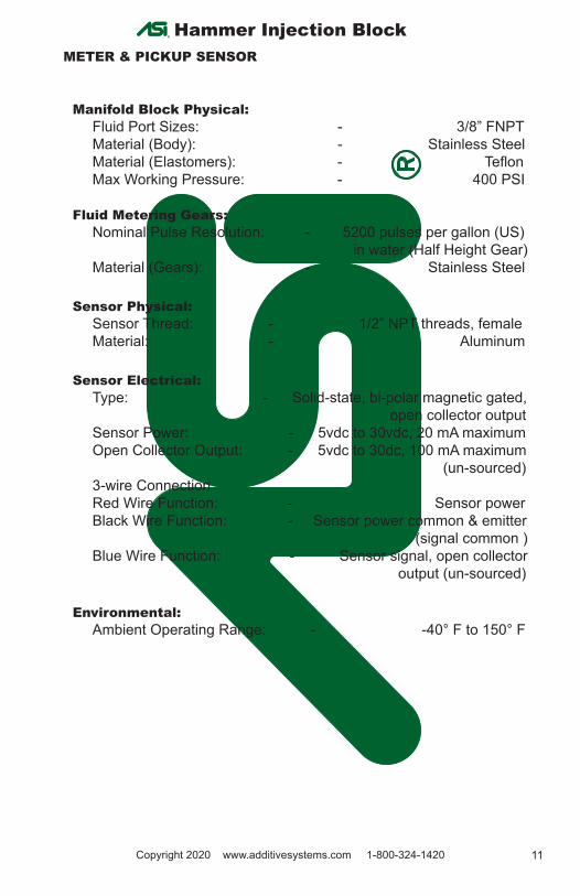
METER & PICKUP SENSOR
Manifold Block Physical:Fluid Port Sizes: - 3/8” FNPTMaterial (Body): - Stainless SteelMaterial (Elastomers): - TeflonMax Working Pressure: - 400 PSI
Fluid Metering Gears:Nominal Pulse Resolution: - 5200 pulses per gallon (US) in water (Half Height Gear)Material (Gears): - Stainless Steel
Sensor Physical:Sensor Thread: - 1/2” NPT threads, femaleMaterial: - Aluminum
Sensor Electrical:Type: - Solid-state, bi-polar magnetic gated, open collector outputSensor Power: - 5vdc to 30vdc, 20 mA maximumOpen Collector Output: - 5vdc to 30dc, 100 mA maximum (un-sourced)3-wire Connection Red Wire Function: - Sensor powerBlack Wire Function: - Sensor power common & emitter (signal common ) Blue Wire Function: - Sensor signal, open collector output (un-sourced)
Environmental:Ambient Operating Range: - -40° F to 150° F
12 Copyright 2020 www.additivesystems.com 1-800-324-1420
AD
DIT
IVE
SY
ST
EM
SIN
C.
“Sin
ce 1
984”
Hammer Injection Block®
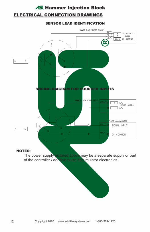
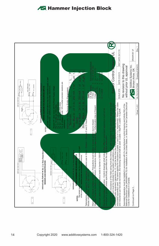
ELECTRICAL CONNECTION DRAWINGS
SENSOR LEAD IDENTIFICATION
WIRING DIAGRAM FOR SOURCED INPUTS
NOTES:The power supply pictured above may be a separate supply or part of the controller / additive pulse accumulator electronics.
13Copyright 2020 www.additivesystems.com 1-800-324-1420
AD
DIT
IVE
SY
ST
EM
SIN
C.
“Sin
ce 1
984”
Hammer Injection Block®
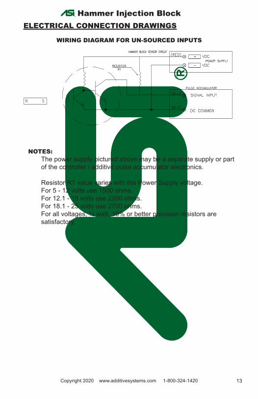
ELECTRICAL CONNECTION DRAWINGS
WIRING DIAGRAM FOR UN-SOURCED INPUTS
NOTES:The power supply pictured above may be a separate supply or part of the controller / additive pulse accumulator electronics.
Resistor R1 value varies with the Power Supply voltage. For 5 - 12 volts use 1500 ohms.For 12.1 - 18 volts use 2200 ohms. For 18.1 - 25 volts use 2700 ohms.For all voltages, ½ watt, 10% or better precision resistors are satisfactory.
14 Copyright 2020 www.additivesystems.com 1-800-324-1420
AD
DIT
IVE
SY
ST
EM
SIN
C.
“Sin
ce 1
984”
Hammer Injection Block®
®
NO
TE
S:
The p
ow
er
supply
pic
ture
d a
bove
may b
e a
separa
te s
upply
or
part
of th
e c
ontr
olle
r / additi
ve p
uls
e a
ccum
ula
tor
ele
ctr
onic
s.
Resi
stor
R1 v
alu
e v
aries
with
the P
ow
er
Supply
voltage.
For
5 -
12 v
olts
use
1500 o
hm
s.F
or
12.1
- 1
8 v
olts
use
2200 o
hm
s.
For
18.1
- 2
5 v
olts
use
2700 o
hm
s.
For
all
volta
ges,
½ w
att, 10%
or
better
pre
cis
ion r
esis
tors
are
satis
fact
ory
.
WIR
ING
DIA
GR
AM
FO
R S
OU
RC
ED
IN
PU
TS
NO
TE
S:
The p
ow
er
supply
pic
ture
d a
bove
may
be a
separa
te s
upply
or
part
of th
e c
ontr
olle
r / additi
ve p
uls
e a
ccum
ula
tor
ele
ctro
nic
s.
Intr
insic
ally S
afe
Div
. 2 o
r N
on
Haza
rdo
us
Intr
insic
ally S
afe
Div
. 2 o
r N
on
Haza
rdo
us
Intr
insic
ally S
afe
Div
. 2 o
r N
on
Haza
rdo
us
WIR
ING
DIA
GR
AM
FO
R U
N-S
OU
RC
ED
IN
PU
TS
SE
NS
OR
LE
AD
ID
EN
TIF
ICA
TIO
N
Term
inals
U
I C
L P
i
i
i
i
i
Red, B
lue to
Bla
ck24 V
dc
1 n
F250 m
A1.5
.4 µ
H
Red to B
lack
24 V
dc
1 n
F250 m
A.7
5.4
µH
Blu
e to B
lack
24 V
dc
1 n
F250 m
A.7
5.4
µH
Intr
insi
cally
Sa
fe D
evi
ce E
ntit
y P
ara
me
ters
:
I m
ax
(or
Li)
≥
Is
c o
r It
(o
r Io
)
TA
BL
E 1
Ci +
Cca
ble
≤
Ca
(o
r C
o)
Li +
Lca
ble
≤
L
a (
or
Lo
)
I.S
. E
qu
ipm
en
t
Ass
oci
ate
d A
pp
ara
tus
P m
ax
(or
Pi)
≥
Po
V m
ax
(or
Ui)
≥
Vo
c o
r V
t (o
r U
o)
W
arn
ing
: E
nce
inte
co
ntie
nt
en
alu
min
ium
. P
réca
utio
ns
do
ive
nt
êtr
e p
rise
s p
ou
r é
vite
r l'i
nfla
mm
atio
n d
ue
à l'
imp
act
.
Mo
de
l: A
SIH
B-1
03
, -4
0°C
< T
a <
65
°C, T
4
Ma
xim
um
ca
ble
le
ng
th f
rom
de
vic
e le
ad
s to
ba
rrie
r is
10
00
ft.
Ca
pa
cita
nce
an
d in
du
cta
nce
of
the
fie
ld w
irin
g f
rom
th
e in
trin
sica
lly s
afe
eq
uip
me
nt
to t
he
ass
oci
ate
d a
pp
ara
tus
sha
ll b
e c
alc
ula
ted
an
d m
ust
be
incl
ud
ed
in t
he
sys
tem
ca
lcu
latio
ns
as
sho
wn
in T
ab
le 1
. C
ab
le c
ap
aci
tan
ce,
Cca
ble
, p
lus
intr
insi
cally
sa
fe e
qu
ipm
en
t ca
pa
cita
nce
, C
i, m
ust
be
le
ss
tha
n t
he
ma
rke
d c
ap
aci
tan
ce,
Ca
(o
r C
o),
sh
ow
n o
n a
ny
asso
cia
ted
ap
pa
ratu
s u
sed
. T
he
sa
me
ap
plie
s fo
r in
du
cta
nce
(L
cab
le,
Li a
nd
La
or
Lo
, re
spe
ctiv
ely
). W
he
re t
he
ca
ble
a
nd
in
du
cta
nce
pe
r fo
ot
are
no
t kn
ow
n,
the
fo
llow
ing
va
lue
s sh
all
be
use
d:
Cca
ble
= 6
0p
F/f
t, L
cab
le =
0.2
µH
/ft.
Wa
rnin
g:
En
clo
su
re c
on
tain
s a
lum
inu
m.
Pre
cau
tion
s m
ust
be
ta
ken
to
avo
id ig
niti
on
du
e t
o im
pa
ct.
Mu
ltip
le A
sso
cia
ted
Ap
pa
ratu
s -
Co
ntr
ol d
raw
ing
s sh
all
ind
ica
te t
ha
t d
iffe
ren
t a
sso
cia
ted
ap
pa
ratu
s m
ust
no
t b
e
co
nn
ect
ed
in p
arr
alle
l un
less
sp
eci
fica
lly p
erm
itte
d b
e t
he
ap
pa
ratu
s ce
rtifi
catio
n.
Ass
oci
ate
d a
pp
ara
tus
mu
st
be
in
sta
lled
in a
cco
rda
nce
with
it’s
ma
nu
fact
ure
r’s
con
tro
l dra
win
g a
nd
Art
icle
50
4 o
f th
e
Na
tion
al E
lect
rica
l Co
de
(A
NS
I/N
FP
A 7
0)
for
inst
alla
tion
in t
he
Un
ited
Sta
tes,
or
Se
ctio
n 1
8 o
r th
e C
an
ad
ian
Ele
ctrica
l C
od
e f
or
inst
alla
tion
s in
Ca
na
da
.
Co
ntin
ue
d o
n P
ag
e 2
...
Tele
me
terin
g E
qu
ipm
en
t fo
r H
aza
rdo
urs
Lo
ca
tio
ns
use
in C
lass
I D
ivis
ion
1 G
rou
ps
C a
nd
D H
aza
rdo
us
Lo
catio
ns
Ad
diti
ve
Syste
ms I
nc.
Bro
ke
n A
rro
w,
OK
.
UL F
ILE
# E
472546
Dra
win
g #
823415
Rev.
1
SC
ALE
NT
SD
AT
E 0
1/2
3/1
5E
DIT
DA
TE
03/1
1/1
5
DR
AW
N B
Y J
F
Sheet 1 o
f 2
Se
nso
r C
on
tro
l Dra
win
g U
L
No
re
visi
on
to
th
is d
raw
ing
w
itho
ut
prio
r U
L a
pp
rova
l
15Copyright 2020 www.additivesystems.com 1-800-324-1420
AD
DIT
IVE
SY
ST
EM
SIN
C.
“Sin
ce 1
984”
Hammer Injection Block®
®
Additi
ve S
yste
ms
Inc.
Bro
ken A
rrow
, O
K.
UL F
ILE
# E
472546
Dra
win
g #
823415
Rev.
1
SC
ALE
NT
SD
AT
E 0
1/2
3/1
5E
DIT
DA
TE
03/1
1/1
5
DR
AW
N B
Y J
F
Sheet 2 o
f 2
Senso
r C
ontr
ol D
raw
ing U
L
No
re
visi
on
to
th
is d
raw
ing
w
itho
ut
prio
r U
L a
pp
rova
l
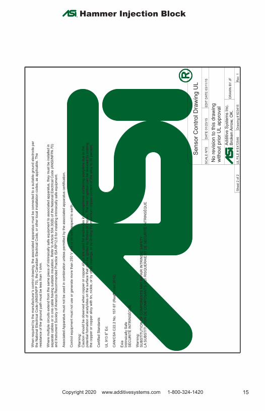
Co
ntr
ol e
qu
ipm
en
t m
ust
no
t u
se
or
ge
ne
rate
mo
re t
ha
n 2
50
V r
ms
or
dc
with
re
spe
ct t
o e
art
h.
Asso
cia
ted
Ap
pa
ratu
s m
ust
no
t b
e u
sed
in c
om
bin
atio
n u
nle
ss p
erm
itte
d b
y th
e a
sso
cia
ted
ap
pa
ratu
s ce
rtifi
catio
n.
Wh
en
re
qu
ire
d b
y t
he
ma
nu
factu
rer’
s c
on
tro
l d
raw
ing
, th
e a
sso
cia
ted
ap
pa
ratu
s m
ust
be
co
nn
ect
ed
to
a s
uita
ble
gro
un
d e
lect
rod
e p
er
the
Na
tion
al E
lect
rica
l Co
de
(A
NS
I/N
FP
70
), t
he
Ca
na
dia
n E
lect
rica
l C
od
e,
or
oth
er
loca
l in
sta
llatio
n c
od
es,
as
ap
plic
ab
le. T
he
re
sis
tan
ce o
f th
e g
rou
nd
pa
th m
ust
be
le
ss t
ha
n 1
oh
m.
Wh
ere
mu
ltip
le c
ircu
its e
xte
nd
fro
m t
he
sa
me
pie
ce
of
intr
insi
ca
lly s
afe
eq
uip
me
nt
to a
sso
cia
ted
ap
pa
ratu
s, t
he
y m
ust
be
in
sta
lled
in
se
pa
rate
ca
ble
s o
r in
on
e c
ab
le h
avin
g s
uita
ble
insu
latio
n.
Re
fer
to A
rtic
le 5
04
.30
(B)
of
the
Na
tio
na
l E
lect
rica
l C
od
e (
AN
SI/
NF
PA
70
) a
nd
In
str
um
en
t S
oci
ety
of A
me
rica
Re
co
mm
en
de
d P
ractice
IS
A R
P1
2.6
fo
r in
sta
llin
g in
trin
sica
lly s
afe
eq
uip
me
nt.
SU
BS
TIT
UT
ION
OF
CO
MP
ON
EN
TS
MA
Y I
MP
AIR
IN
TR
INS
IC S
AF
ET
Y
Wa
rnin
g: th
U
L 9
13
8E
d.
Exi
a
Ce
rtifi
ed
Sta
nd
ard
s
SÉ
CU
RIT
É I
NT
RIN
SÈ
QU
E
Ca
utio
n s
ho
uld
be
ob
se
rve
d w
he
n c
op
pe
r o
r co
pp
er
allo
ys a
re u
sed
fo
r e
ncl
osu
res
in a
tmo
sph
ere
s co
nta
inin
g a
cety
len
e d
ue
to
th
e
po
ten
tial f
orm
atio
n o
f a
cety
lide
s o
n t
he
su
rfa
ce
th
at
ca
n b
e ig
nite
d b
y f
rict
ion
or
imp
act
. T
he
ris
k o
f ig
nitio
n c
an
be
re
du
ced
by
coa
tin
g
the
co
pp
er
or
cop
pe
r a
lloy w
ith t
in,
nic
kle
, o
r b
y o
the
r co
atin
gs,
or
by li
mitin
g t
he
ma
xim
um
co
pp
er
con
ten
t o
f th
e a
lloy
to 3
0 p
erc
en
t.
CA
N/C
SA
C2
2.2
No
. 1
57
-97
(R
ea
ffirm
ed
20
12
)
Wa
rnin
g:
LA
SU
BS
TIT
UT
ION
DE
CO
MP
OS
AN
TS
QU
I R
ISQ
UE
RA
IEN
T D
E S
ÉC
UR
ITÉ
IN
TR
INS
ÈQ
UE
Intr
insic
ally
Sa
fe
16 Copyright 2020 www.additivesystems.com 1-800-324-1420
AD
DIT
IVE
SY
ST
EM
SIN
C.
“Sin
ce 1
984”
Hammer Injection Block®
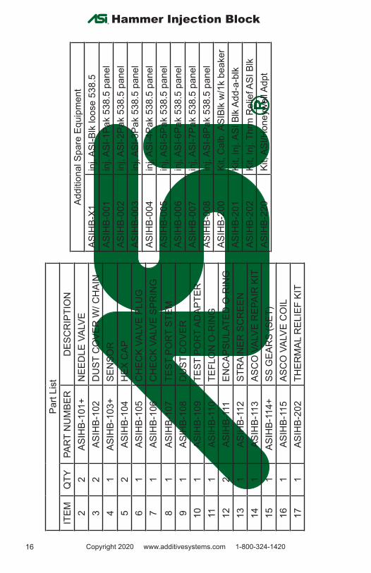
Addi
tiona
l Spa
re E
quip
men
tAS
IHB-
X1in
j, AS
I-Blk
loos
e 53
8.5
AS
IHB-
001
inj,
ASI-1
Pak
538.
5 pa
nel
ASIH
B-00
2in
j, AS
I-2Pa
k 53
8.5
pane
lAS
IHB-
003
inj,
ASI-3
Pak
538.
5 pa
nel
ASIH
B-00
4in
j, AS
I-4Pa
k 53
8.5
pane
lAS
IHB-
005
inj,
ASI-5
Pak
538.
5 pa
nel
AS
IHB-
006
inj,
ASI-6
Pak
538.
5 pa
nel
ASIH
B-00
7in
j, AS
I-7Pa
k 53
8.5
pane
lAS
IHB-
008
inj,
ASI-8
Pak
538.
5 pa
nel
ASIH
B-20
0Ki
t, C
alb.
ASI
Blk
w/1
k be
aker
ASIH
B-20
1Ki
t, In
j. AS
I Blk
Add
-a-b
lk
ASIH
B-20
2Ki
t, In
j. Th
rm R
elie
f ASI
Blk
ASIH
B-22
0Ki
t, AS
I/Hon
eyw
ell A
dpt
Part
List
ITEM
QTY
PAR
T N
UM
BER
DES
CR
IPTI
ON
22
ASIH
B-10
1+N
EED
LE V
ALVE
32
ASIH
B-10
2D
UST
CO
VER
W/ C
HAI
N4
1AS
IHB-
103+
SEN
SOR
52
ASIH
B-10
4H
EX C
AP6
1AS
IHB-
105
CH
ECK
VALV
E PL
UG
7
1AS
IHB-
106
CH
ECK
VALV
E SP
RIN
G8
1AS
IHB-
107
TEST
PO
RT
STEM
91
ASIH
B-10
8D
UST
CO
VER
101
ASIH
B-10
9TE
ST P
OR
T AD
APTE
R11
1AS
IHB-
110
TEFL
ON
O-R
ING
122
ASIH
B-11
1EN
CAP
SULA
TED
O-R
ING
131
ASIH
B-11
2ST
RAI
NER
SC
REE
N14
1AS
IHB-
113
ASC
O V
ALVE
REP
AIR
KIT
151
ASIH
B-11
4+SS
GEA
RS
(SET
)16
1AS
IHB-
115
ASC
O V
ALVE
CO
IL
171
ASIH
B-20
2TH
ERM
AL R
ELIE
F KI
T
17Copyright 2020 www.additivesystems.com 1-800-324-1420
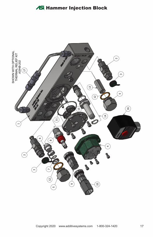
Hammer Injection Block®PA
RTS
LIST
DESC
RIPT
ION
PART
NUM
BER
QTY
ITEM
INJE
CTOR
BLO
CKAS
IHB-
100
11
NEED
LE V
ALVE
AS
IHB-
101
22
DUST
COV
ER W
/ CH
AIN
ASIH
B-10
22
3
SENS
ORAS
IHB-
103
14
HEX
CAP
ASIH
B-10
42
5CH
ECK
VALV
E PL
UG
(PTF
E)AS
IHB-
105
16
CHEC
K VA
LVE
SPRI
NGAS
IHB-
106
17
TEST
POR
T ST
EMAS
IHB-
107
18
DUST
COV
ERAS
IHB-
108
19
TEST
POR
T CO
UPLE
RAS
IHB-
109
110
TEFL
ON O
-RIN
GAS
IHB-
110
111
ENCA
PSUL
ATED
O-
RING
ASIH
B-11
12
12
STRA
INER
SCR
EEN
ASIH
B-11
21
13AS
CO V
ALVE
REP
AIR
KIT
ASIH
B-11
31
14
SS G
EARS
(SET
)AS
IHB-
114
115
ASCO
VAL
VE C
OIL
ASIH
B-11
51
16TH
ERM
AL R
ELIE
F KI
TAS
IHB-
202
117
1 1
2 2
3 3
4 4
AA
BB
Edit
Date
:Dr
awn
By:
Rev.
Draw
ing
Num
ber:
Addi
tive
Syst
ems
Inc.
Date
:Sc
ale:
08/0
7/19
J.F.
ASIH
B-00
0
Ham
mer
Blo
ck Expl
oded
Vie
w
Shee
t:1
of 1
Rev.
#Re
visio
nsDa
te
NTS
05/3
1/13
5
1
2
3
3
2
13
12
5
16
14
15
6
712
58
11
4
9 10
17
SHO
WN
WIT
H O
PTIO
NAL
SH
OW
N W
ITH
OPT
ION
AL
THER
MAL
REL
IEF
KIT
THER
MAL
REL
IEF
KIT
AS
IHB
-202
AS
IHB
-202
18 Copyright 2020 www.additivesystems.com 1-800-324-1420
AD
DIT
IVE
SY
ST
EM
SIN
C.
“Sin
ce 1
984”
®ADDITIVE SYSTEMS INC
“Since 1984”Quality Control Statement
Additive Systems Inc. Broken Arrow, Oklahoma is the owner operated factory where ASI Hammer Injection Blocks are manufac-tured, assembled and tested. ASI Hammer Injection Blocks undergo a series of Quality Assurance tests during the course of manufacturing. The Quality Control tests are performed on finished products to verify the initial performance and consistent repeatability of product output units, including performance with special materials, etc. A typical Quality Control test consists of meter accuracy and assured operational power to the pick-up coil. ASI Hammer Injection Blocks are tested as a complete unit before shipping through ASI’s distribution ware-house and ultimately the end user.
• Parts manufactured for ASI are accepted to a tolerance of +or- .001” • ASI Hammer Injection Blocks are leak tested at 500psi for 30 minutes• Fully assembled ASI Hammer Injection Blocks are tested to a field simulation for 10 gallons at 4 second intervals injections, con-firming injection accuracy
ASI WarrantyAdditive Systems Inc. warrants the ASI Hammer Injection Block manufactured by ASI to be free from defects in workmanship or material for a period of one (1) year* from date of startup, provided that in no event shall this warranty extend more than eighteen (18) months form the date of sale.
ASI assumes no liability for consequential damages of any kind and purchaser by acceptance of delivery assumes all liability for the consequences of the use or misuse of ASI products by the purchaser, his employees or others. ASI will assume no field expense for service or parts unless written authorization for it is received in advance.
This is ASI’s sole warranty and is in lieu of all other warranties, expressed or implied, which are hereby excluded, including in particular all warranties of merchantability or fitness for a particular purpose. No officer or employee of Additive Systems Inc. is authorized to alter this warranty.

19Copyright 2020 www.additivesystems.com 1-800-324-1420
AD
DIT
IVE
SY
ST
EM
SIN
C.
“Sin
ce 1
984”
Hammer Injection Block®
Notes:
20 Copyright 2020 www.additivesystems.com 1-800-324-1420
AD
DIT
IVE
SY
ST
EM
SIN
C.
“Sin
ce 1
984”
Hammer Injection Block®
Products• Custom fabricate to your spec’ in steel, aluminum, SS, etc.• Industrial, commercial, agricultural, residential• Gasoline, Diesel, Biodiesel, CNG, Ethanol, Jet, Water, etc.• Turnkey Truck Racks, Blending Skids, Metering Skids• High Pressure Sampling Pumps• Leak-Free Magnetically-Coupled Gear Pumps• SS Hammer Industrial Duty Magnetically-Coupled Pumps• Tanks built to virtually any size• OSHA Standards, NFPA Specifications • Custom Vent Hatches• Mercaptan Injection Systems• Desiccant Filters, Specialty Breathers• Additive Monitoring and Management Systems• Custom containment pans • Ladders, Platforms, Cages • Mechanical Gauges • ”Red-line” Tank Gauges
Service• Turnkey Installation of Additive Equipment• Quality Preventative Maintenance Programs• Complete System Calibration• Retrofit Installation of existing equipment• General Maintenance• Complete CAD Services and Design• Systems Replacement and Upgrades• Over 250 Years Combined Employee Experience• Guarantee the Job Is Done Right• Tailored jobs for specific requirements