addressing heterogeneity in omg d&c-based...
TRANSCRIPT

Addressing Heterogeneity in OMG D&C-based Deployment
Lubomír Bulej 1,2, Tomáš Bureš 1,2
1 Charles University, Faculty of Mathematics and Physics, Department of Software Engineering
Malostranske namesti 25, 118 00 Prague 1, Czech Republic {bulej,bures}@nenya.ms.mff.cuni.cz
http://nenya.ms.mff.cuni.cz
2 Academy of Sciences of the Czech Republic Institute of Computer Science
{bulej,bures}@cs.cas.cz http://www.cs.cas.cz
Abstract. The OMG Deployment and Configuration specification is an attempt at standardizing the deployment process of component-based applications in distributed environment. A software connector is an abstraction capturing interaction among components. Apart from middleware independence, connectors provide additional services (e.g. adaptation, monitoring, etc.) and benefits, especially in the area of integration of heterogeneous component-based applications. This paper presents an approach for using connectors in the context of deployment process defined by the OMG Deployment and Configuration specification to overcome incompatibilities in different component models and allow for a true heterogeneous deployment.
1. Introduction and motivation
Component-based software engineering is a paradigm advancing a view of constructing software from reusable building blocks, components. A component is typically a black box with a well defined interface, performing a known function. The concept builds on the techniques well known from modular programming, which encourage the developers to split a large and complex system into smaller and better manageable functional blocks and attempt to minimize dependencies between those blocks.
Pursuing the vision of building software from reusable components, the component-based software engineering paradigm puts a strong emphasis on design and modeling of software architectures, which allows for reuse of both implementation and application design. The high level abstractions employed in
This work was partially supported by the Grant Agency of the Czech Republic project 102/03/0672. The results will be applied in the OSMOSE/ITEA project.

2 Lubomír Bulej, Tomáš Bureš
architecture modeling often lack support in the existing technology, so an emphasis is put also on developing support for runtime binding of components, flexible communication mechanisms, or deployment of component applications in distributed environment.
Some of the ideas have been embraced by the software development industry and as a result, there are now several component models, which are extensively used for production of complex software systems. The well-known models include Enterprise Java Beans [24] by Sun Microsystems, CORBA Component Model [18] by OMG, and .Net [14] by Microsoft.
There are a large number of other component models, designed and used mainly by the academic community. While most of the academic component models lack the maturity of their industrial counterparts, they aim higher with respect to fulfilling the vision of the component-based software engineering paradigm. This is mainly reflected in support for advanced modeling features, such as component nesting, or connector support. Of those we are familiar with, we should probably mention SOFA [22, 17], Fractal [16], and Darwin [13].
One of possibly several common problems of most component models is the deployment of component-based applications. Most of the existing component models have attempted to address the issue in some way, but the differences between various component models have made it difficult to arrive at a common solution. The differences comprise mainly component packaging and deployment, communication middleware, hierarchical composition, component instantiation, and lifecycle management. As a result, integration and maintenance of component applications implemented in different component models is very difficult.
The deployment process generally consists of several steps, which have to be performed in order to successfully launch an application, and is typically specific to particular component technology and vendor. Consequently, even applications written with specific technology in mind have to be deployed in a way specific to the vendor of the (standardized) technology and the vendor’s proprietary tools.
The specification by Object Management Group [20] aims to lay a foundation for an industrial standard for deployment and configuration of component-based distributed applications. Since it does not explicitly address deployment and configuration of heterogeneous component applications, as a part of our research, we are attempting to design and develop tools compatible with the OMG D&C specification that would allow for deployment of heterogeneous component applications. To demonstrate the problems associated with deployment of heterogeneous component applications as well as the feasibility of our approach, we have decided to support deployment of component applications with components written using SOFA, Fractal, and EJB.
One of the main problems inherent to deployment of heterogeneous component applications is related to interconnection of components from different component models. The problem arises mainly due to 1) different middleware used by the component models to achieve distribution, and 2) different ways of instantiating components and accessing their interfaces.
Of the three mentioned component models, SOFA offers the most freedom in the choice of middleware, as it has native support for software connectors, which allow using almost arbitrary middleware for communication. Fractal, on the other hand,

Addressing Heterogeneity in OMG D&C-based Deployment 3
supports distribution with its own middleware based on serialization defined by RMI [26]. The middleware is, however, not compatible with classic SUN RMI. Finally, EJB uses SUN RMI to achieve distribution.
Regarding the component instantiation mechanisms, the SOFA and the Fractal component models are quite similar. Both employ the concept of factory (component builder in SOFA, generic factory in Fractal) for creating component instances, yet they differ substantially in the way a component structure is described. The SOFA model describes the structure statically, using SOFA-specific ADL called Component Definition Language. In Fractal, the description of the structure is dynamic, passed as a parameter to the generic factory. However, still there is still a distinction between components’ code and code for instantiating and binding of components.
The EJB component model, on the other hand, bears very little similarity to either of the discussed models. The EJB component model supports four different kinds of components, beans: a) entity beans, stateful, the state is persistent and usually stored in a database, b) stateful session beans, the state of which is preserved for the duration of a session, c) stateless session beans, which are quite similar to libraries, and d) message-driven beans, which are similar to stateless session beans, except they lack the classic business interface, and instead process incoming requests in a message loop. Every component has a business interface and a home interface. The home interface of a bean is used to instantiate components of a specific kind, and in case of entity beans, restore component state from the database. Bean home interfaces can be obtained through naming service. The actual instantiation is performed from components’ and client’s code. Prior to any request to the naming service, a bean has to be first deployed into an EJB container, using implementation-specific deployment tools. Unlike the SOFA and the Fractal models, EJB does not support component nesting.
To overcome the differences between these models, we have decided to use software connectors to facilitate the bridging between these technologies. Software connectors encapsulate all communication among components and are typically responsible for 1) distribution (employing a communication middleware), 2) adaptation (hiding changes in method names, and order of arguments, or performing more complex transformation), and 3) additional services (e.g. encryption, communication monitoring, etc.). Being such a flexible concept, the connectors fit very well in our approach.
2. Goals and structure of the text
Although a connector based approach appears to be very promising for our project, the OMG D&C specification does not support connectors natively. Instead, the components are meant to be directly interconnected. Therefore, the concept of connectors has to be first integrated into the specification. To preserve compatibility with the OMG D&C specification, we would like the integration of connectors to have minimal impact on the original specification, and attempt to map the connectors onto concepts already present in the specification. With regard to the discussion above, the goal of this paper is to show

4 Lubomír Bulej, Tomáš Bureš
• how to use connectors in a deployment framework compatible with the OMG D&C specification, and
• how to utilize connectors to overcome the differences between the selected component models. The rest of the paper is organized as follows. To introduce the context of our work,
Section 3 gives an overview of the relevant parts of the OMG D&C specification. Section 4 then presents an overview and key features of our connector model and explains what a deployment of a component-based application with connectors looks like. Having explained the related topics, Section 5 shows how to utilize connectors in the scope of OMG D&C specification. Section 6 then presents a simple case study demonstrating the use of connectors to overcome the differences between the three component models. We discuss related work in Section 7 and conclude the paper with summary and future work in Section 8 and Section 9, respectively.
3. Overview of OMG D&C Specification
The deployment and configuration of component-based distributed application describes the relation between three major abstractions. First, there is a component-based application, which consists of other components, the application itself being a component considered independently useful. Then there is a target environment, termed domain, which provides computational resources for execution of component-based applications. And finally, there is a deployment process, which takes a component-based application and a target environment as an input and produces an instance of the application running in the target environment as a result.
Given enough information about the application and the target environment, the deployment process is expected to be reasonably generic, especially at higher levels of abstraction. The required information is made available to the process in form of detailed description with a standardized data model. To allow for specialization at lower levels of abstraction, the OMG specification is compliant with the Model Driven Architecture (MDA) [21], also defined by OMG. The core of the specification defines a set of concepts and classes relevant for the implementation of the specification, which forms a platform independent model (PIM) of the specification. The model can be the transformed to platform specific models (PSM), which can capture the specifics of particular component middleware technology, programming language, or information formatting technology.
The component model defined by the core specification is explicitly independent of distributed component middleware technology such as CORBA CCM [18] or EJB [24]. Components can be either implemented directly (a monolithic implementation), or by an assembly of other components. The hierarchical composition allows for capturing logical structure of an application and a configuration of an assembly of components. Ultimately, though, every application can be decomposed into a set of components with monolithic implementation, which is required for deployment.
The target environment, a domain, consists of nodes, interconnects and bridges. Of these, only the nodes provide computational resources, while interconnects group

Addressing Heterogeneity in OMG D&C-based Deployment 5
nodes that are able to communicate directly within a domain. A situation where the nodes cannot, for some reason (e.g. a firewall, an application proxy), communicate directly is modeled by grouping the nodes in different interconnects. Bridges are then used to facilitate communication between nodes in different interconnects.
The deployment process consists of five stages, termed installation, configuration, planning, preparation, and launch. Prior to deployment, the application must be
packaged and made available by the producer. The package has to contain all relevant meta-data describing the application as well as binary code and data, required to run the application.
To minimize the amount of interdependencies and to lower the overall complexity of the platform independent model, the specification defines two dimensions for segmenting the model into modules. The first dimension provides a distinction between a data model of the descriptive information and a management model of runtime entities, which process the information. The second dimension takes into account the role of the models in the deployment process, and distinguishes among component, target, and execution models.
Since giving a complete overview of the whole specification is far beyond the scope of this paper, we have selected only the parts required to understand the context of the presented work. Of the modules mentioned earlier, we will only describe the component and execution data models, and provide a brief description of the deployment process with emphasis on the planning stage.
3.1. Component Data Model
The component data and management models are mainly concerned with description of and manipulation with component software packages. The description specifies requirements that have to be satisfied for successful deployment, most of which are independent of a particular target system. Both the application metadata and code artifacts are expected to be stored and configured in a repository during the installation and configuration stages of the deployment. The information will be then accessed and used during the planning, and preparation stages.
Figure 1 shows a high level overview of the component data model. The key concept here is a component package, which contains the configuration and implementation of a component. If a component has multiple implementations, the configuration should specify selection requirements, which influence deployment decisions by matching the requirements to capabilities of individual implementations.
Each component package realizes a component interface, which is implemented by possibly multiple component implementations. Figure 2 shows a detailed view of a component interface description. A component interface is a collection of ports, which can participate as endpoints in connections among components. A collection of properties carries component interface configuration.

6 Lubomír Bulej, Tomáš Bureš
Fig. 1. An overview of the component data model
Fig. 2. A detailed view of the component interface description
As shown in Figure 1, an implementation of a component can be either monolithic, or an assembly of other components. In case of monolithic implementation, the description of the implementation consists of a list of implementation artifacts that make up the implementation. The artifacts can depend on each other and, which is not shown on the figure, can carry a set of deployment requirements and execution parameters. The requirements have to be satisfied before an artifact can be deployed on a node.
Addressing Heterogeneity in OMG D&C-based Deployment 7
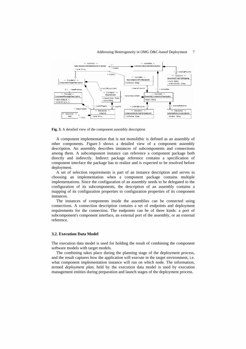
Fig. 3. A detailed view of the component assembly description
A component implementation that is not monolithic is defined as an assembly of other components. Figure 3 shows a detailed view of a component assembly description. An assembly describes instances of subcomponents and connections among them. A subcomponent instance can reference a component package both directly and indirectly. Indirect package reference contains a specification of component interface the package has to realize and is expected to be resolved before deployment.
A set of selection requirements is part of an instance description and serves in choosing an implementation when a component package contains multiple implementations. Since the configuration of an assembly needs to be delegated to the configuration of its subcomponents, the description of an assembly contains a mapping of its configuration properties to configuration properties of its component instances.
The instances of components inside the assemblies can be connected using connections. A connection description contains a set of endpoints and deployment requirements for the connection. The endpoints can be of three kinds: a port of subcomponent's component interface, an external port of the assembly, or an external reference.
3.2. Execution Data Model
The execution data model is used for holding the result of combining the component software models with target models.
The combining takes place during the planning stage of the deployment process, and the result captures how the application will execute in the target environment, i.e. what component implementation instance will run on which node. The information, termed deployment plan, held by the execution data model is used by execution management entities during preparation and launch stages of the deployment process.

8 Lubomír Bulej, Tomáš Bureš
Fig. 4. An overview of the execution data model
Figure 4 shows a high level overview of the execution data model with additional details exposed in some of the classes. The deployment plan is analogous to the description of component assembly, and in fact contains a flattened view of the top level component assembly which represents the whole application. Of the original logical structure of the application, only the information required to create component instances and connections is retained. There is not, however, a direct mapping between all the classes in the component and execution data models.
The classes capturing the composition of individual artifacts into component implementations, instantiation of components and the connections among components are similar to those of the component data model, but not identical. This adds a significant amount of flexibility to the deployment process. If e.g. the component data model is extended to support other, possibly higher level, abstractions for which code can be automatically generated, the planner tool performing the transformation from the component data model to the execution data model can also generate the required code (or have other application do it on demand) and augment the resulting deployment plan so that it reflects the higher level abstractions in implementation.
3.3. Deployment Process
The deployment process as defined by the OMG specification consists of five stages. Prior to deployment, the software must be developed, packaged, and published by the provider and obtained by the user. The target environment in which the software is to run consists of nodes, interconnects and bridges, and contains a repository, in which the software package can be stored.
Installation During the installation stage, the software package is put into a repository, where it will be accessible from other stages of deployment. The location of the repository is

Addressing Heterogeneity in OMG D&C-based Deployment 9
not related to the domain the software will execute in, and the installation also does not involve any copying of files to individual nodes in a domain.
Configuration When the software is in the installation repository, its functionality can be configured by the deployer. The software can be configured multiple times for different configurations, but the configuration should not concern any deployment related decisions or requirements. The configuration stage is meant solely for functional configuration of the software.
Planning After a software package has been installed into a repository and configured, the deployer can start planning the deployment of the application. The process of planning involves selection of computational nodes the software will run on, the resources it will require for execution, deciding which implementations will be used for instantiation of components, etc. The planning does not have any immediate effect on the environment.
The planning stage of deployment is probably the most powerful concept of the specification. The result of planning is a deployment plan, which is specific to the target environment and the software being deployed. The plan is produced by transforming the information from the component data model into execution data model. Higher level abstractions in the component data model can be interpreted by the planner tool and transformed into deployment primitives of the deployment plan. In this stage, the planner or planner plugins can generate additional code artifacts, resolve indirect artifact or component package references, and transform the logical view of the component application into the physical view of the application, which is required for deployment.
An example of such a higher level abstraction are software connectors. While the original specification intends the connections among component interface ports to be direct, indirect communication can be achieved by modifying the planner to interpret requirements of individual endpoints in a connection and synthesize a connector implementation with desired features. The original component model can be then automatically adjusted to reflect the use of connectors for communication among components. The resulting component model is then transformed into deployment plan, which will describe the newly created artifacts and connections.
Preparation Unlike planning, the preparation stage involves performing work in the target environment in order to prepare the environment for execution of the software. If the software is to be executed more than once according to the same plan, the work performed during the preparation stage is reusable. The actual moving of files to computational nodes in the domain can be postponed until the launch of the application.
10 Lubomír Bulej, Tomáš Bureš
Launch The application is brought to the executing state during the launch stage. As planned, instances of components are created and configured on target nodes and the connections among the instances are established. The application runs until it is terminated.
4. Software Connectors
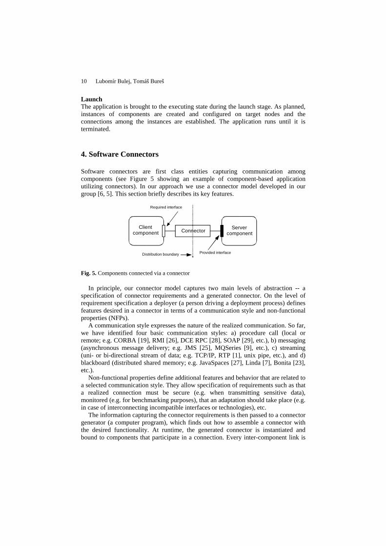
Software connectors are first class entities capturing communication among components (see Figure 5 showing an example of component-based application utilizing connectors). In our approach we use a connector model developed in our group [6, 5]. This section briefly describes its key features.
Distribution boundary Provided interface
Required interface
ConnectorClient
componentServer
component
Fig. 5. Components connected via a connector
In principle, our connector model captures two main levels of abstraction -- a specification of connector requirements and a generated connector. On the level of requirement specification a deployer (a person driving a deployment process) defines features desired in a connector in terms of a communication style and non-functional properties (NFPs).
A communication style expresses the nature of the realized communication. So far, we have identified four basic communication styles: a) procedure call (local or remote; e.g. CORBA [19], RMI [26], DCE RPC [28], SOAP [29], etc.), b) messaging (asynchronous message delivery; e.g. JMS [25], MQSeries [9], etc.), c) streaming (uni- or bi-directional stream of data; e.g. TCP/IP, RTP [1], unix pipe, etc.), and d) blackboard (distributed shared memory; e.g. JavaSpaces [27], Linda [7], Bonita [23], etc.).
Non-functional properties define additional features and behavior that are related to a selected communication style. They allow specification of requirements such as that a realized connection must be secure (e.g. when transmitting sensitive data), monitored (e.g. for benchmarking purposes), that an adaptation should take place (e.g. in case of interconnecting incompatible interfaces or technologies), etc.
The information capturing the connector requirements is then passed to a connector generator (a computer program), which finds out how to assemble a connector with the desired functionality. At runtime, the generated connector is instantiated and bound to components that participate in a connection. Every inter-component link is
Addressing Heterogeneity in OMG D&C-based Deployment 11
realized by a unique instance of connector (more precisely by a unique instance of a connector unit as explained later in this section).
The connector generator relies on two basic concepts – connector and element architectures [2] and primitive element templates [5].
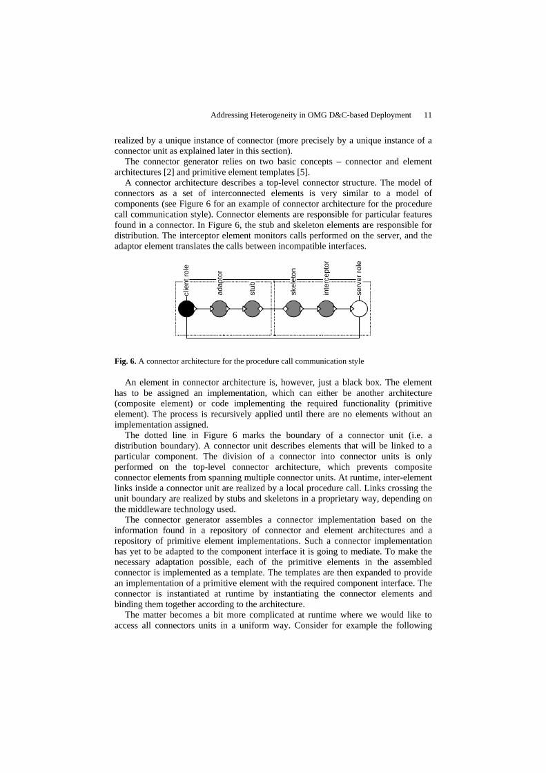
A connector architecture describes a top-level connector structure. The model of connectors as a set of interconnected elements is very similar to a model of components (see Figure 6 for an example of connector architecture for the procedure call communication style). Connector elements are responsible for particular features found in a connector. In Figure 6, the stub and skeleton elements are responsible for distribution. The interceptor element monitors calls performed on the server, and the adaptor element translates the calls between incompatible interfaces.
stub
clie
nt ro
le
adap
tor
skel
eton
inte
rcep
tor
serv
er ro
le
Fig. 6. A connector architecture for the procedure call communication style
An element in connector architecture is, however, just a black box. The element has to be assigned an implementation, which can either be another architecture (composite element) or code implementing the required functionality (primitive element). The process is recursively applied until there are no elements without an implementation assigned.
The dotted line in Figure 6 marks the boundary of a connector unit (i.e. a distribution boundary). A connector unit describes elements that will be linked to a particular component. The division of a connector into connector units is only performed on the top-level connector architecture, which prevents composite connector elements from spanning multiple connector units. At runtime, inter-element links inside a connector unit are realized by a local procedure call. Links crossing the unit boundary are realized by stubs and skeletons in a proprietary way, depending on the middleware technology used.
The connector generator assembles a connector implementation based on the information found in a repository of connector and element architectures and a repository of primitive element implementations. Such a connector implementation has yet to be adapted to the component interface it is going to mediate. To make the necessary adaptation possible, each of the primitive elements in the assembled connector is implemented as a template. The templates are then expanded to provide an implementation of a primitive element with the required component interface. The connector is instantiated at runtime by instantiating the connector elements and binding them together according to the architecture.
The matter becomes a bit more complicated at runtime where we would like to access all connectors units in a uniform way. Consider for example the following

12 Lubomír Bulej, Tomáš Bureš
function: bindToRemoteReference(Reference ref). The function is responsible for establishing a remote connection between client and server connector units. Although the processing of this function call is in most cases delegated to a stub element, we cannot rely on it. We have to access a connector unit as a black-box. Therefore, a connector unit has to implement these control functions and (with knowledge of its own structure) delegate them to appropriate connector elements (i.e. the stub element in our example).
We implement the required control functions by adding a special element (called element manager) to each connector unit and composite element. The control interface it exposes is subsumed to the "frame" of encapsulating connector unit or composite element. The element manager knows the structure of the connector unit/composite element it resides in and delegates the control function calls to corresponding elements (in fact its neighbors). Since the services realized by the element manager are mostly an implementation detail, we do not reflect this element in connector unit/composite element architectures.
5. Solution
The OMG D&C specification is very comprehensive, but also fairly complex. To allow use of connectors for mediating communication among components, we only have to deal with parts of it. Most of the work concerned with generation of connectors will be done at planning stage. The specification itself requires some modifications to the component data model to allow for specification of desired connector features for every connection among components (using communication style and non-functional properties), a way of transforming the modified specification to the base component and execution data models, and a way of ensuring correct instantiation of connectors and establishing of connections at application launch.
Figure 7 shows an example of a simple component application using a connector to mediate the communication between the Client and the Server components. The example will be used throughout this section to demonstrate the approach we have chosen.
5.1. Specification of connector features
To generate a connector, a connector generator needs to have enough information concerning the requirements for the communication the connector is expected to mediate. The specification of connector features has a form of communication style and non-functional properties. Each connection among instances of components in an assembly can have different requirements.

Addressing Heterogeneity in OMG D&C-based Deployment 13
Client Server
cRol
e
sRol
e
skel
etonstub
elem
ent
man
ager
elem
ent
man
ager
NodeBNodeA
Fig. 7. An example of a component application using a connector
Fig. 8. The modification of the AssemblyConnectionDescription class
The original OMG D&C platform independent component data model requires a minor extension to allow for specification of connector features. We have added another association, identical to that of deployRequirement, but named connectionRequirement to the AssemblyConnectionDescription class. The reason for not using the existing deployRequirement is to avoid overloading the semantics of the deployRequirement association, the contents of which are matched against requirement satisfiers describing resources available on the nodes in a domain.
Figure 8 shows the modified AssemblyConnectionDescription class with the new connectionRequirement association. The XML fragments shown bellow are parts of the component data model description of the simple application depicted in Figure 7. The connectionRequirement element contains a description a connection requirements.
ExampleApplication.cpd
<componentPackageDescription> <label>Example Application</label>

14 Lubomír Bulej, Tomáš Bureš
<realizes href="ExampleApplicationIfc.cfd"/> <implementation> <name>Example Application Implementation</name> <referencedImplementation href= "ExampleApplicationImpl.cid"/> </componentPackageDescription>
ExampleApplicationImpl.cid
<componentImplementationDescription> <label>Example Application Implementation</label> <assemblyImpl> <instance id="1"> <name>Client Component</name> <basePackage href="ClientComponent.cpd"/> </instance> <instance id="2"> <name>Server Component</label> <basePackage href="ServerComponent.cpd"/> </instance> <connection> <name>Connection between Client and Server components</name> <internalEndpoint> <instance idref="1"/> <portName>ClientComponentInterfacePort</portName> </internalEndpoint> <internalEndpoint> <instance idref="2"/> <portName>ServerComponentInterfacePort</portName> </internalEndpoint> <connectionRequirement> <resourceType>connectionType</resourceType> <property> <name>allow-remote</name><value>true</value> </property> <property> <name>comm-style</name><value>procedure call</value> </property> </connectionRequirement> </connection> </assemblyImpl> <implements href="ExampleApplicationIfc.cfd"/> </componentImplementationDescription>
5.2. Transformation of the component application description
During the planning stage of the deployment process, a planning tool aware of the connection requirements communicates with a connector generator [6] and provides it with information necessary to build a connector for each connection in the application. In addition to the connection requirements specified in the description of

Addressing Heterogeneity in OMG D&C-based Deployment 15
the component application, the tool can also provide information on the assignment of connection endpoints to individual nodes in a domain as well as information on resources available on each of the nodes. The connector generator creates the necessary connector code and the connector-aware part of the planning tool transforms the original application description specifying connection requirements into a new description, which reflects the changes required to deploy connectors along with the original components.
The transformation adds instances of connector units into the application description and decomposes the original connections so that for each endpoint of the original connection, a new connection is created, connecting the component endpoint to an endpoint of connector unit instance. The original connection is then replaced with a new connection connecting the connector units together. The resulting description of component application adheres to the original OMG D&C specification of component data model, with connectors represented by regular components. This description can be then transformed to deployment plan by flattening the logical structure of the application description.
The following XML fragment describes the implementation of the simple application depicted in Figure 7 after the connectors have been integrated into the original description. Note the new component instances and connections.
ExampleApplicationImpl.cid
<componentImplementationDescription> <label>Example Application Implementation</label> <assemblyImpl> <instance id="1"> <name>Client Component</name> <basePackage href="ClientComponent.cpd"/> </instance> <instance id="2"> <name>Server Component</name> <basePackage href="ServerComponent.cpd"/> </instance> <instance id="3"> <name>ClientComponentInterfacePort Unit</name> <importedPackage> <location> repository://ClientComponentInterfacePortUnit.cpd </location> </importedPackage> </instance> <instance id="4"> <name>ServerComponentInterfacePort Unit</name> <importedPackage> <location> repository://ServerComponentInterfacePortUnit.cpd </localtion> </importedPackage> </instance> <connection>

16 Lubomír Bulej, Tomáš Bureš
<name>Connection between Client component and unit</name> <internalEndpoint> <instance idref="1"/> <portName>ClientComponentInterfacePort</portName> </internalEndpoint> <internalEndpoint> <instance idref="3"/> <portName>ServerComponentInterfacePort</portName> </internalEndpoint> </connection> <connection> <name>Connection between Server component and unit</name> <internalEndpoint> <instance idref="2"/> <portName>ServerComponentInterfacePort</portName> </internalEndpoint> <internalEndpoint> <instance idref="4"/> <portName>ClientComponentInterfacePort</portName> </internalEndpoint> </connection> <connection> <name>Connection between Client and Server units</name> <internalEndpoint> <instance idref="3"/> <portName>ClientComponentInterfacePort</portName> </internalEndpoint> <internalEndpoint> <instance idref="4"/> <portName>ServerComponentInterfacePort</portName> </internalEndpoint> </connection> </assemblyImpl> <implements href="ExampleApplicationIfc.cfd"/> </componentImplementationDescription>
5.3. Instantiation of connectors
A connector has to be instantiated from top to bottom, starting with a connector unit and the corresponding element manager. Then the elements on the next level are instantiated. In case of composite connector elements, the process has to be applied recursively until all the primitive elements are reached. Since the OMG D&C specification does not support ordering of instantiation of individual components, decomposing the internal structure of connectors into components and connections so as to let the execution management entities instantiate the connector elements would not produce the expected result.
Instead of modification of the OMG D&C specification of the deployment process, the instantiation of a connector is a responsibility of an element/unit factory. For that it needs to know the internal structure of the connector. Since the connector code is generated, code for instantiating specific connector architecture can be generated as well. A more flexible solution though, is to pass a description of connector structure

Addressing Heterogeneity in OMG D&C-based Deployment 17
to a generic element/unit factory through execution parameters in the description of connector implementation.
6. Case Study – A connector support for SOFA, Fractal and EJB
In this section we present how to map the connector support we have introduced to the OMG D&C to the three selected component models. Our goal was to create such a mapping that would not raise the necessity of rewriting the existing components.
Pragmatically, the whole trick of using connectors is to plug an appropriate connector instance between every two components. More specifically, it means attaching a server connector unit to every provided interface and letting every required interface point to a client connector unit. This is easily done by hooking in the process of component instantiation and binding. Upon instantiation of a component we create the server connector units and make sure that whenever component interfaces are queried a connector reference to a corresponding server connector unit is returned (instead of a reference to the interface). Similarly, whenever an interface is being connected to another component, a client connector unit is created and bound using the connector reference. In our approach, the connector reference is a container holding a set of server unit identities depending on available transport methods (e.g. Java reference for in-address-space connections, RMI reference for RMI connections, or IOR for CORBA connections).
The information what implementation is to be used for a particular connector unit is contained in a global connector configuration map. The map contains couples <connector unit discriminator, implementation>. The connector unit discriminator is either a triple <dock name, component frame, interface name> in the case of server connector units, or a 6-tuple <server dock name, server component frame, server interface name, client dock name, client component frame, client interface name> in the case of client connector units. Such a description reflects the fact that a server connector unit is created in advance and can exist standalone, while a client connector unit is created during component binding when the binding target is already known.
Having such a modified runtime, we can easily map connectors from the OMG D&C specification to filling in the global connector configuration map. The runtime then takes care of the connector instantiation. Our approach thus introduces connectors as a distinct runtime construct not modifying the original architecture of a component application.
Such an approach works theoretically pretty well; however, it is not always straightforward how to apply it to different component models. In the case of the three component models we have chosen, it means no change for SOFA, as this component model is already equipped with connectors and their instantiation complies with what we have described so far.
In Fractal, it is sufficient to hook in the component instantiation process by modifying the binding controller. (Fractal uses AOP for the implementation of controllers, so it is relatively easy to extend or modify the behavior of the default controllers.) The only difficulty is that Fractal permits calling provided component interfaces directly (i.e. without binding it to a required interface first), which can

18 Lubomír Bulej, Tomáš Bureš
result in code casting a connector reference to a business interface, which is an error. To overcome this problem we introduce so called shared client connector units. Unlike “classical” client connector units, these are not associated with a particular client component. A shared connector is created for each connector reference and is used thorough the whole dock instead of the direct use of the connector reference. When a component is about to be bound to a shared client connector unit (as it would be normally bound to a connector reference), a new client connector unit is created and connected to a server connector unit (using the reference contained in the shared client connector unit). Using this approach we still achieve own client connector units for every component, while allowing to access component interfaces without binding them first. As the client connector is built without knowledge of the client component, its connector unit discriminator for the global connector configuration map takes the form of 4-tuple <server dock name, server component frame, server interface name, client dock name>.
Server connector unit
Shared client connector unit
Client connector unit(associated with a component)
Component AComponent B
Component C
Fig. 9. An example of a shared connector usage. The component A holds a reference (the circle) to an interface of the component C. The reference points to a shared client connector unit which is connected to a server connector unit bound to the interface of the component C. The shared client unit can be passed through another connector (e.g. to the component B). When the component B is regularly bound to the component C using the shared client unit, a new client connector unit is created and used instead.
Establishing a connector support for EJB is similar to Fractal. As EJB has no notion of required interfaces, all the client connector units are shared (i.e. when two components in the same dock access the same interface of a particular server component, they share the instance of the client connector unit). To hook in the instantiation process we use our own implementation of the JNDI naming context from which references to bean homes are obtained.

Addressing Heterogeneity in OMG D&C-based Deployment 19
7. Evaluation and related work
In this paper, we have presented an approach which allows using software connectors in the context of OMG D&C specification. The original platform independent component data model assumes direct communication among component endpoints in a connection. This assumption requires that a connection to be described at a lower level of abstraction than e.g. the structure of the component application, because it has to connect ports provided by specific artifacts. As a consequence, the description of the component application cannot abstract from e.g. a middleware technology used for communication in distributed environment.
Enhancing the description of a connection among components with the specification of communication style and non-functional properties allows e.g. the selection of communication middleware to be postponed until the planning stage of the deployment, or introduction of logging, monitoring, or encryption facilities into communication without changing the description of the component application.
To our knowledge, there is no other work concerning use of connectors in the OMG D&C specification or other deployment orchestration framework. There are, however, a number of mature business solutions for interconnecting the leading business component models such as EJB [24], CCM [18], and .NET [14]. A common denominator of these models is the lack of certain features (e.g. component nesting), which makes the problem of their interconnection a matter of middleware bridging. Each of those component models has a native middleware for communication in distributed environment (RMI [26] in case of EJB, CORBA [19] in case of CCM, and .NET remoting in case of .NET). A middleware bridge is usually realized as a "bridge" component translating one middleware protocol to another. A list of leading middleware bridges comprises:
• Borland Janeva [4] – Allows for interconnection of .NET applications with
CORBA objects. It uses CORBA IIOP natively and provides a tool for generating .NET proxies. The proxies are then added into the resulting .NET assembly, thus allowing for easier deployment of the .NET part.
• ObjectWeb DotNetJ [15] – Allows to call Java classes or even EJB components from .NET applications. It starts a dedicated JVM with class implementing the .NET remoting protocol. Remotely called Java classes are loaded directly to the JVM, calls to EJB components (residing in another JVM) are transformed to RMI calls.
• Intrinsyc J-Integra for .NET [10] – Works in a way similar to DotNetJ. Uses .NET remoting as a native protocol and allows to bridge .NET and EJB technologies. Unlike DotNetJ, allows for calls in both directions.
• BEA WebLogic [3] – More a middleware suite than just a middleware bridge. Allows accessing CORBA servers from EJB via a designated bridge.
• IONA Orbix [11] – Also a rather comprehensive middleware suite, similar to BEA WebLogic. It builds on CORBA infrastructure. It provides bridges for EJB, COM and .NET clients allowing them to access CORBA objects. All of them are based on deploying a "bridge" component into respective component technology.

20 Lubomír Bulej, Tomáš Bureš
• IONA Artix [12] – A full-fledged SOAP middleware. Provides "bridge" classes for EJB and CORBA technologies that accept SOAP calls and delegate them to appropriate components/objects. The bridging is only done in one direction.
• K2 [8] – An implementation of CCM container. Allows for integration with EJB via an EJB bridge. Natively supports also SOAP [29], thus allowing for seamless integration with Web Services. Even though these bridges represent mature software products, they do not provide
a standardized approach. All the listed bridges are proprietary solutions of individual vendors. Usually, they were either created to achieve a specific goal of connecting two particular platforms (e.g. DotNetJ) or they were originally created as an ORB middleware and evolved into a more robust solution later, allowing to accommodate other platforms. Nevertheless, the bridging only works in one direction (e.g. .NET, EJB clients accessing CORBA object in case of Orbix, or EJB component accessing CORBA services in case of WebLogic).
In our approach, we address heterogeneity from the very beginning. We use the platform independent component data model defined in the OMG D&C specification to describe a component application. Our extension of the component data model also does not introduce any platform or language dependencies. Component interconnections are modeled by connectors, which are created for a specific platform and language during the planning stage of the deployment process. A connector is generated for each of the connections, which allows for adaptation of the connector to the platforms on which the connection endpoints reside.
The adaptation of the connector to the connection endpoint's platform results in no or minimal overhead for local connections, small overhead for connections between identical platforms (e.g. using RMI for connecting Java to Java), and moderate overhead when connecting originally incompatible platforms (e.g. Java to .NET using SOAP). All connections are two-way, without any specialized code in the component implementation, which allows for smooth building of heterogeneous component applications.
8. Summary
We have presented an approach for using software connectors in deployment frameworks compatible with OMG D&C specification. The use of connectors eases the deployment and interconnection of heterogeneous component-based distributed applications, the components of which can be implemented in different component models. We have only needed to introduce a very minor change into the specification for it to support specification of connection requirements.
The description and implementation of connectors is mapped into already present concepts and classes (i.e. component packages, monolithic component implementation, implementation artifact). The presented solution is generic, described in a platform independent way, and allows mapping to different component models.

Addressing Heterogeneity in OMG D&C-based Deployment 21
To justify our approach we have shown how to model connectors in three component systems (namely SOFA, Fractal and EJB) we have selected as representatives of the wide spectrum of component models.
9. Future work
The presented solution relies on a connector generator capable of creating connectors with respect to a high-level specification and generates their implementation for different component models and middleware technologies. We currently have a prototype implementation of such a connector generator for the SOFA and Fractal component system. The generator needs to be extended to allow us to automatically generate connectors even for the EJB component model.
References
[1] Audio-Video Transport Working Group, RTP: A Transport Protocol for Real-Time Applications, RFC 1889, Jan 1996
[2] Balek, D., Plasil, F., Software Connectors and Their Role in Component Deployment, Proceedings of DAIS'01, Krakow, Kluwer, Sep 2001
[3] BEA WebLogic 8.1, http://www.bea.com, 2003 [4] Borland Janeva 6.0, http://www.borland.com/janeva, 2004 [5] Bulej, L., Bures, T., A Connector Model Suitable for Automatic Generation of Connectors,
Tech. Report No. 2003/1, Dep. of SW Engineering, Charles University, Prague, Jan 2003 [6] Bures, T., Plasil, F., Communication Style Driven Connector Configurations, Copyright
Springer-Verlag, Berlin, LNCS3026, ISBN: 3-540-21975-7, ISSN: 0302-9743, pp. 102-116, 2004
[7] Gelernter, D., Generative communication in Linda, ACM Transactions on Programming Languages and Systems, pp. 80-112, Jul 1985
[8] iCMG, K2 Component Server 1.5, http://www.icmgworld.com/corp/k2/k2.overview.asp, 2003
[9] IBM Corporation, WebSphere MQ family, http://www-306.ibm.com/software/integration/mqfamily/, Apr 2002
[10] Intrinsyc, J-Integra for .NET, http://j-integra.intrinsyc.com/, 2004 [11] IONA Technologies PLC, Orbix 6.1, http://www.iona.com/products/orbix.htm, 2004 [12] IONA Technologies PLC, Artix 2.1, http://www.iona.com/products/artix, 2003 [13] Magee, J., Dulay, N., Kramer, J., Regis: A Constructive Development Environment for
Distributed Programs, In IEE/IOP/BCS Distributed Systems Engineering, 1(5), pp. 304-312, Sep 1994
[14] Microsoft Corporation, .NET, http://www.microsoft.com/net, 2004 [15] ObjectWeb Consortium, DotNetJ, http://dotnetj.objectweb.org, 2003 [16] ObjectWeb Consortium, Fractal Component Model, http://fractal.objectweb.org, 2004 [17] ObjectWeb Consortium, SOFA Component Model, http://sofa.objectweb.org, 2004 [18] Object Management Group, Corba Components, version 3.0,
http://www.omg.org/docs/formal/02-06-65.pdf, Jun 2002 [19] Object Management Group, Common Object Request Broker Architecture: Core
Specification, version 3.0.3, http://www.omg.org/docs/formal/04-03-12.pdf, Mar 2004

22 Lubomír Bulej, Tomáš Bureš
[20] Object Management Group, Deployment and Configuration of Component-based Distributed Applications Specification, http://www.omg.org/docs/ptc/04-08-02.pdf, Feb 2004
[21] Object Management Group, Model Driven Architecture, http://www.omg.org/docs/ormsc/01-07-01.pdf, Jul 2001
[22] Plasil, F., Balek, D., Janecek, R., SOFA/DCUP: Architecture for Component Trading and Dynamic Updating, Proceedings of ICCDS'98, Annapolis, Maryland, USA, IEEE CS Press, May 1998
[23] Rowstron, A., Wood, A., BONITA: A set of tuple space primitives for distributed coordination, Proceedings of the 30th Annual Hawaii International Conference on System Sciences. Published by the IEEE Computer Society Press, 1997
[24] Sun Microsystems, Inc., Java 2 Platform Enterprise Edition Specification, version 1.4, http://java.sun.com/j2ee/j2ee-1_4-fr-spec.pdf, Nov 2003
[25] Sun Microsystems, Inc., Java Message Service Specification, version 1.2, http://java.sun.com/products/jms/docs.html, Apr 2002
[26] Sun Microsystems, Inc., Java Remote Method Invocation Specification, ftp://ftp.java.sun.com/docs/j2se1.4/rmi-spec-1.4.pdf, 2001
[27] Sun Microsystems, Inc., Java Spaces Service Specification, version 2.0, http://wwws.sun.com/software/jini/specs/js2_0.pdf, Jun 2003
[28] The Open Group, Inc., DCE 1.1: Remote Procedure Call, Aug 1997 [29] World Wide Web Consortium, SOAP, version 1.2, http://www.w3.org/2000/xp/Group/,
Jun 2003