addressing hospital staffing shortages
TRANSCRIPT

a D D R e s s I n G H o s P I t a l s t a f f I n G s H o R t a G e s
abstractSeveral hospitals face nurse staffi ng shortages for surgeries. This research focuses on building a system with a Baxter robot capable of identifying surgical tools using computer vision and delivering them to the surgeon on demand. This would deal with the issue of nurse unavailability during simple surgical procedures. The key aspects of the project were testing the accuracies of various artifi cial neural networks (ANNs) in classifying surgical instruments and programming Baxter to implement a surgical tool delivery system using magnets at the tip of its 7 degrees of freedom (DOF) robotic arms. The methodology consisted of fi rst implementing algorithms to enable Baxter to do pick and deliver tasks for surgical tools, and second, gathering HuMoments of various tools using the cameras on Baxter's arm, which were then used to train the ANNs. Tool detection accuracies of ANNs with hidden layer neuron number varying from 5–50 and learning rates varying from 0.005‒0.1 were collected. Then, the tool identifi cation and tool delivery system were merged together to create a turn-by-turn dynamic tool tracking and delivery system, which retrieved tools, based on the surgeons input, through a Leap Motion Controller. In addition to delivery, the system was modifi ed to retrieve used tools from the surgeon, using a computer vision-based approach. The optimal ANN confi guration consisted of an ensemble of various ANNs working together and achieved a detection accuracy of 93%. The average time taken for a mock abdominal incision surgery with the system is expected to be around 10 minutes and 30 seconds.
Parida, S. (2015). Addressing hospital staffi ng shortages: Dynamic surgical tool tracking and delivery using Baxter. Journal of Purdue Undergraduate Research, 5, 72–81. http://dx.doi.org/10.5703/jpur.05.1.09
Keywordscomputer vision, neural networks, Baxter, intelligent systems, surgical tool detection, machine learning, Robot Operating System (ROS), tool classifi cation, multi-ANN systems, gesture-based input, surgical tool delivery
Sthitapragyan (Sid) Parida is a junior in computer engineering and mathematics, interested in the applicability of machine learning algorithms to solve problems that arise in everyday life. He was a participant in the 2014 Summer Undergraduate Research Fellowship (SURF) program in Dr. Juan Pablo Wachs’ Intelligent Systems and Assistive Technologies (ISAT) Laboratory.
Student author
Juan Pablo Wachs is an assistant professor at Purdue University, at the School of Industrial Engineering. Previously, he was a postdoctoral fellow at the Naval Postgraduate School’s MOVES Institute, where he worked on problems related to body posture recognition, subresolution tracking, and surveillance applications. He completed his PhD on the intelligent systems track, entitled "Hand Gesture Vocabularies Design." His current focus is on two connected disciplines related to machine vision: intelligent systems and human-machine interfaces.
Maria Eugenia Cabrera completed her master’s degree, working with the Mechatronics Research Group at Simón Bolivar University in Venezuela. Currently, she is a part of the ISAT Laboratory, pursuing her doctorate under the guidance of Dr. Juan Pablo Wachs, where she is studying the possibility of switching from joystick interfaces to touchless ones to control robots used in robotic-assisted surgery (RAS).
Mentors
72 journal of purdue undergraduate research: volume 5, fall 2015http://dx.doi.org/10.5703/jpur.05.1.09

inTRoduCTion
In recent years, hospitals have started facing a dearth of nursing staff (Janes, 2014). In numerous medical work-places, an adequate number of nurses are unavailable to cater to the number of surgeries performed, which leads to critical delays in making proper treatment available to patients. Overwork and understaffi ng leads to nursing errors, which can be avoided by using alternative measures.
Robots, since the information revolution of the 1980s, have made a profound impact on industry and revolutionized the ways products are manufactured and assembled, leading to a culture of mass production. Lately, robots have been found to be a viable alternative to manpower in diverse areas of medical interest. Currently, most of the applications focus on remote control of robots by expert surgeons—a fi eld of ever-increasing applicability—called remote sur-gery (Ayache, Delingette, Golland, & Mori, 2012). Tech-nological breakthroughs like the Da Vinci robot have made remote surgery both possible and viable, and are being used by a number of medical facilities around the world.
In our effort to address the nurse shortage problem, it was nat-ural to consider the possibility of using robots. Consequently, this research project took a different approach to the appli-cability of robots during surgery. A big part of a nurse’s job description involves making the proper tools available to the surgeon at the right time, enabling the surgeon to devote com-plete attention to the actual task at hand. This research focused on developing a system that was capable of proper tool deliv-ery to surgeons, on demand, and retrieval of the tools after use.
In the course of the research, a surgical tool tracking and delivery system capable of identifying surgical tools placed
randomly on a table using ANNs (Marsland, 2009) was implemented with Baxter, a research robot manufactured by Rethink Robotics. The system was capable of delivering tools to the surgeon on demand and retrieving tools back after use. The tools were tracked at regular intervals over the entire period of the surgery, enabling the robot to work in a more realistic surgery scenario, where the conditions are chaotic and the position of objects cannot be assumed to be constant.
The following sections take a thorough look at the com-position of the subsystems comprising the fi nal system, the role they play in the fi nal system, and the calibration processes necessary to ensure seamless operation of the system. Thereafter, the results from the initial system are presented, along with an analysis of the preliminary results. Based on the initial analysis, modifi cations and further improvements are discussed (see Figure 1).
Figure 1. Final system layout including system components.
Sthitapragyan Parida, Electrical and Computer Engineering
a D D R e s s I n G H o s P I t a l s t a f f I n G s H o R t a G e s :Dynamic Surgical Tool Tracking and Delivery Using Baxter
Baxter delivery arm
Retrieval Box
Magnet
Retrieval zone
Camera arm
Tool Table
addressing hospital staffing shortages 73

MeThodS
Baxter works on the Robot Operating System (ROS) frame-work designed by Willow Garage. As stated on the official ROS website, ROS is a collection of tools and libraries that make writing software for robotic systems simpler and more efficient. Programs that utilize the ROS framework can be programmed in C++ and Python, and usually need an Ubuntu system to function. For this project, Python, along with an Ubuntu workstation running Precise Pango-lin (Ubuntu 12.04), was chosen to design the system. Bax-ter communicated with the workstation through the ROS framework on the Ubuntu machine, which in turn was con-trolled by the Python (Oliphant, 2007) programs.
The final system was capable of receiving user input for the selection of a tool. The robot identified the tool selected using computer vision, figured out a path to pick the tool up, and delivered it to the surgeon. After use, the robot retrieved the tool and stored it away from the sur-gery. Accordingly, the system consisted of three subsys-tems working in unison: tool request, tool identification, and tool delivery/retrieval. Calibration programs were
used to smoothly transition through the two coordinate frames used in the system: Baxter 3-D world space and 2-D image coordinates. Figure 2 depicts the final system and its subsystems.
Tool Request
Traditionally, human-computer interaction has been domi-nated by serial lines of communication using a mouse or a keyboard. During a surgery, either method is ineffective. A more intuitive and natural method of input was sought so that surgeons can concentrate on the surgery, rather than deviate their attention on actual tool request. Motivated by the goal of keeping surgeon-system interaction as natural as possible, and guided by the observation that surgeons com-municate with nurses using hand gestures, a hand gesture-based tool request system was agreed upon. A Leap Motion Controller was used to track the surgeon’s hands during surgery. The sensor communicated with the Ubuntu work-station through a USB port and provided real-time 3-D data about the surgeon’s hand position, orientation, finger count, finger joint velocities, and so forth.
Figure 2. Final system process flow along with subsystems.
74 journal of purdue undergraduate research: volume 5, fall 2015

The finger count data was used to differentiate between indi-vidual tools. As the finger count can range from 0 through 5, for testing purposes a predetermined set of 6 tools was selected. Each tool corresponded to a specific finger count. The set of tools along with their corresponding finger count are listed in Table 1. The finger count of the number also known as the Unique Tool ID, was used to represent the tool internally in the Python scripts.
Table 1. Tool set and unique tool identification of each tool.
The data obtained from the Leap Motion Controller was further utilized to keep track of the occurrence of a simple key-tap gesture needed for temporal segmentation. The finger count was recorded continually, regardless of the surgeon’s intent to request a tool. Therefore, the key-tap gesture was adopted as a temporal segmentation technique to initiate the tool request sequence. Whenever the surgeon wanted a tool, he/she, would perform a key-tap gesture and then extend the appropriate number of fingers correspond-ing to the specific tool choice. The system would then pass the Unique Tool ID to the system for tool identification and subsequent delivery to the surgeon.
Tool delivery/Retrieval
We decided to use Baxter, a research robot with two 7 degrees of freedom (DOF) robotic arms for tool delivery. Each arm has seven joints that could be manipulated to move the arm to any point in 3-D space around the robot while maintaining a specific orientation for the endpoint of the arm. An inbuilt red-green-blue (RGB) camera at the endpoint facilitated object detection and location. The left arm of Baxter was equipped with a gripper kit, attached with a permanent magnet, which was used to pick up the metallic tools used in the surgery. The camera on the right arm was used to map the tool area and provide input to the tool identification system. The camera on the left arm was used to track the tool retrieval area for the presence of tools that needed to be retrieved.
The reason we chose Baxter as our test robot was because it had an inbuilt collision avoidance system and could stop moving when it sensed human presence or a bulk object around it, therefore minimizing risk and damage to the
surgical setting and surgeons themselves. In addition, Baxter was equipped with an on-board inverse kinematics solver, IKFast, which had been optimized to work with Baxter’s 7 DOF arms. This streamlined the movement of the arms and eliminated the need for an external path planning system.
Tool Delivery
Baxter’s left arm rested in a neutral position directly above the tool retrieval location when not delivering a tool. The delivery sequence was initiated by the tool identification system, which provided the tool delivery system with the 2-D pixel coordinates of the centroid of the requested tool in the image captured by Baxter’s right arm. The 2-D image coordinates were converted to 3-D Baxter space coordinates using the rotation and translation matrix obtained from calibration process (described later). The 3-D Baxter world space coor-dinates were provided to the inbuilt IKFast in Baxter. IKFast also received the quaternion representation of the orientation of the tip of the delivery arm from the orien-tation control system. The algorithm finally output the joint space values for the delivery arm of Baxter, which were used by ROS to actually move the arm. See Figure 2 for reference.
Upon being triggered, the left delivery arm was moved to the center of the surgical table in a quick motion and was slowly lowered onto the tool. The tool was picked up by the magnet on contact and then the arm was moved to the delivery location, which was prespecified as a particular set of joint space values. After delivery, the arm moved back to the neutral position and monitoring of the retrieval zone resumed.
Tool Retrieval
The camera at the bottom plane of Baxter’s delivery arm was used to track the retrieval zone. In a process similar to delivery, on being triggered the delivery arm moved to the centroid of the tool. The tool was picked up using the magnet at the tip and then the arm moved to the retrieval box, placed away from the surgical area. The tool was low-ered into the box though a linear slit on the top surface of the box. Once inside, the orientation of the arm changed so that as the arm moved away, the tool was held back in the box by the flaps at the top surface. After retrieval, the arm moved back to the neutral position.
Orientation Control
During operation, the orientation of Baxter’s arm was controlled using the orientation control system. Although Baxter ships with an in built IKFast Solver, quaternions are used to specify orientation, which can be counterintuitive
Finger Count Tool Unique Tool
ID1 Scalpel 02 Retractor 13 Hemostat 24 Scissors 35 Hook 46 Needle 5
addressing hospital staffing shortages 75
to the human mind. Hence, a program was devised that takes as input a unit vector in 3-D space, which specifies the orientation. The program output the necessary qua-ternion orientation of the unit vector, which was directly used in the IKFast Solver afterward. As a result, Baxter’s arm could move to a specific 3-D position and point in a specific direction while at that position. The 3-D unit vector was converted to Euler angles using the following equations:
As a point of interest, Γ was independent of the unit vector used to specify the orientation, as it represented the rotation of the arm around the axis passing through Baxter’s arm. (The gamma value was manipulated during disposal to ensure that the tool was oriented perpendicular to the slit in the box). Rotation matrices Rx, Ry, and Rz, were constructed out of the Euler angles, as the angles Θ, Φ, and Γ specified rotation around the X, Y, and Z axes, respectively.
These matrices were concatenated to form the final rotation matrix Rfinal.
Finally, the quaternion representation was calculated from Rfinal.
Tool Identification
The tool identification process is the heart of the system. The right arm of Baxter, which is not used for delivery, has a camera at the bottom plane and is used for capturing images. After mapping the tools present on the surgical area, pixel coordinates of the centroids of these tools are obtained. These pixel coordinates are converted into 3-D Baxter space coordinates, using the transformation matrix obtained during the calibration process described later. For tool identification, we chose to use ANNs as the base classifier and tested their efficiency in a variety of scenar-ios. All image processing algorithms were implemented using OpenCV (Bradski, 2000), because it is open source, free, and a potent and robust library for image processing. It also comes with a subset of tools required for the sys-tem, which is inbuilt into the library. A breakdown of the steps involved follows.
Obtain Image
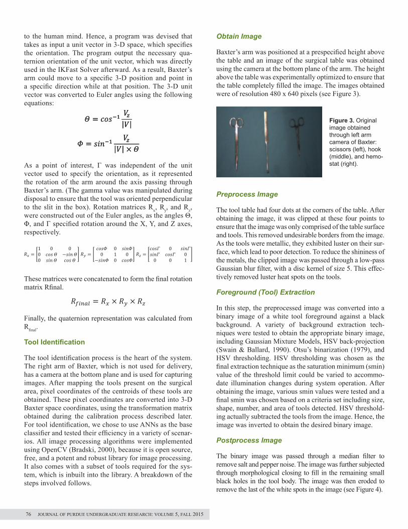
Baxter’s arm was positioned at a prespecified height above the table and an image of the surgical table was obtained using the camera at the bottom plane of the arm. The height above the table was experimentally optimized to ensure that the table completely filled the image. The images obtained were of resolution 480 x 640 pixels (see Figure 3).
Preprocess Image
The tool table had four dots at the corners of the table. After obtaining the image, it was clipped at these four points to ensure that the image was only comprised of the table surface and tools. This removed undesirable borders from the image. As the tools were metallic, they exhibited luster on their sur-face, which lead to poor detection. To reduce the shininess of the metals, the clipped image was passed through a low-pass Gaussian blur filter, with a disc kernel of size 5. This effec-tively removed luster heat spots on the tools.
Foreground (Tool) Extraction
In this step, the preprocessed image was converted into a binary image of a white tool foreground against a black background. A variety of background extraction tech-niques were tested to obtain the appropriate binary image, including Gaussian Mixture Models, HSV back-projection (Swain & Ballard, 1990). Otsu’s binarization (1979), and HSV thresholding. HSV thresholding was chosen as the final extraction technique as the saturation minimum (smin) value of the threshold limit could be varied to accommo-date illumination changes during system operation. After obtaining the image, various smin values were tested and a final smin was chosen based on a criteria set including size, shape, number, and area of tools detected. HSV threshold-ing actually subtracted the tools from the image. Hence, the image was inverted to obtain the desired binary image.
Postprocess Image
The binary image was passed through a median filter to remove salt and pepper noise. The image was further subjected through morphological closing to fill in the remaining small black holes in the tool body. The image was then eroded to remove the last of the white spots in the image (see Figure 4).
� � ����� ��|�|
� � ����� ��|�| � �
�� � �1 0 00 ����� ������0 ����� �����
� �� � ����� 0 ����0 1 0
����� 0 ����� �� � �
���� 0 �������� ���� 00 0 1
�
������ � �� � �� � ��
� � ���� ��� ������ ��� ���1 1 1
� � � � ���� ��� ������ ��� ������ ��� ���
�
� � � ����
� � ����� ��|�|
� � ����� ��|�| � �
�� � �1 0 00 ����� ������0 ����� �����
� �� � ����� 0 ����0 1 0
����� 0 ����� �� � �
���� 0 �������� ���� 00 0 1
�
������ � �� � �� � ��
� � ���� ��� ������ ��� ���1 1 1
� � � � ���� ��� ������ ��� ������ ��� ���
�
� � � ����
� � ����� ��|�|
� � ����� ��|�| � �
�� � �1 0 00 ����� ������0 ����� �����
� �� � ����� 0 ����0 1 0
����� 0 ����� �� � �
���� 0 �������� ���� 00 0 1
�
������ � �� � �� � ��
� � ���� ��� ������ ��� ���1 1 1
� � � � ���� ��� ������ ��� ������ ��� ���
�
� � � ����
Figure 3. Original image obtained through left arm camera of Baxter: scissors (left), hook (middle), and hemo-stat (right).
� � ����� ��|�|
� � ����� ��|�| � �
�� � �1 0 00 ����� ������0 ����� �����
� �� � ����� 0 ����0 1 0
����� 0 ����� �� � �
���� 0 �������� ���� 00 0 1
�
������ � �� � �� � ��
� � ���� ��� ������ ��� ���1 1 1
� � � � ���� ��� ������ ��� ������ ��� ���
�
� � � ����
76 journal of purdue undergraduate research: volume 5, fall 2015

Find Contours
The postprocessed image was passed through OpenCV’s findContours function, based on Suzuki and Be’s border-fol-lowing algorithm (1985). A list of contours of the white blobs that represented the different tools in the image was obtained. The contours were lists of 2-D pixel coordinates. Properties of these contours including arc length, hierarchy index, and contour area were calculated using OpenCV (see Figure 5).
Filter Contours
The initial list of contours contained contours other than that of the tools. To screen these unwanted contours, two criteria were used. First, only base contours with no par-ents (enclosing contours) were selected. This was based on the hierarchy list of contours provided by OpenCV, and hence, only contours with parent ID of -1 were selected. Further, only contours with a boundary perimeter greater than 400 were chosen for subsequent analysis. This ensured that smaller contours of holes in the background were not identified as tools.
Calculate Modified HuMoments
To increase the speed of the identification process and reduce training time for the neural networks used for iden-tification, instead of working directly with the contours, 2-D shape descriptors were used to represent the contours. HuMoments were chosen to represent the homomorphism between the 2-D contour points and the shape descriptors. HuMoments are a set of seven numbers invariant to transla-tion scaling and rotation in a plane. They are used to repre-sent a 2-D contour or image in a succinct manner.
Due to the invariability of the HuMoments to rotation, translation, and scaling, the tool identification process
was unaffected by the location, size, and orientation of the tools (Huang & Leng, 2010). However, as proposed by Flusser and Suk (2006), the set of seven HuMoments is incomplete, and following their work an eighth moment was included in the set. Thereafter, each tool was repre-sented by 8 HuMoment Invariants. Figure 6 depicts the calculation of HuMoments from the scale of invariant moments represented by η.
Figure 6. Calculation of HuMoments, I1 through I8.
Pass to ANN and Identify Tool
Neural networks were used to classify the HuMoments obtained and identify different tools. The set of 8 HuMo-ments was passed to the ANN as input, and finally the net-work classified the tool into one of the six tool categories mentioned earlier. The details of the ANN configuration are described in the next section (see Figure 7).
Neural Network Configuration and Training
The ANNs used in the system were simple three-layer net-works (Mitchell, 1997) including the input layer, hidden layer, and output layer, that used backpropagation for learn-ing (Nielsen, 2014). Various configurations were tested to gather a sufficiently large base of neural networks to exam-ine identification accuracy. Each data point used in the pro-cess was a set of 8 HuMoments representing a specific tool. The gathered data was split into different sets for proper training, validation, and testing. Table 2 presents the num-ber of data points used for each case.
Figure 4. Binary image obtained after background subtrac-tion and postpro-cessing.
Figure 5. Individual contour obtained via Suzuki and Be’s border-following algorithm (1985).
Figure 7. Output of ANN, identifying contour as a hook. The green dot at the center indi-cates the centroid.
addressing hospital staffing shortages 77
ANN Configuration
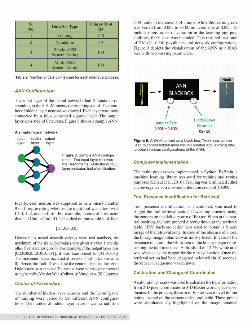
The input layer of the neural networks had 8 inputs corre-sponding to the 8 HuMoments representing a tool. The num-ber of hidden layer neurons was varied. Each layer was inter-connected by a fully connected sigmoid layer. The output layer consisted of 6 neurons. Figure 8 shows a sample ANN.
Ideally, each neuron was supposed to be a binary number 0 or 1, representing whether the input tool was a tool with ID 0, 1, 2, and so forth. For example, in case of a retractor that had Unique Tool ID 1, the ideal output would look like:
[0,1,0,0,0,0]
However, as neural network outputs were real numbers, the maximum of the six output values was given a value 1 and the other five were assigned 0. For example, if the output layer was [0.2,0.88,0.1,0.05,0.3,0.1], it was transformed to [0,1,0,0,0,0]. The maximum value occurred at position 1 (if index started at 0). Hence, the Tool ID was 1, so the neuron identified the set of HuMoments as a retractor. The vectors were internally represented using NumPy (Van der Walt, Colbert, & Varoquaux, 2011) arrays.
Choice of Parameters
The number of hidden layer neurons and the learning rate of training were varied to test different ANN configura-tions. The number of hidden layer neurons was varied from
5‒50 units in increments of 5 units, while the learning rate was varied from 0.005 to 0.100 in increments of 0.005. To include three orders of variation in the learning rate pos-sibilities, 0.001 also was included. This resulted in a total of 210 (21 x 10) possible neural network configurations. Figure 9 depicts the visualization of the ANN as a black box with two varying parameters.
Figure 9. ANN visualized as a black box. Two knobs can be used to control hidden layer neuron number and learning rate, to obtain various configurations of the ANN.
Computer Implementation
The entire process was implemented in Python. PyBrain, a machine learning library was used for training and testing purposes (Schaul et al., 2010). Training was terminated either at convergence or a maximum iteration count of 10,000.
Tool Presence Identification for Retrieval
Tool presence identification, as mentioned, was used to trigger the tool retrieval action. It was implemented using the camera on the delivery arm of Baxter. When at the neu-tral position, the arm pointed directly down at the retrieval table. HSV back-projection was used to obtain a binary image of the retrieval zone. In case of the absence of a tool, the binary image obtained was mostly black. In case of the presence of a tool, the white area in the binary image repre-senting the tool increased. A threshold of 12.5% white area was selected as the trigger for the retrieval action. Once the retrieval action had been triggered twice within 10 seconds, the retrieval sequence was initiated.
Calibration and Change of Coordinates
A calibration process was used to calculate the transformation from 2-D pixel coordinates to 3-D Baxter world space coor-dinates. In the process, the arm of Baxter was moved to four points located on the corners of the tool table. These points were simultaneously highlighted on the image obtained
Sl. No. Data Set Type Unique Tool
ID1 Training 2402 Validation 60
3 Single-ANN System Testing 100
4 Multi-ANN System Testing 100
Table 2. Number of data points used for each individual process.
Figure 8. Sample ANN configu-ration. The input layer receives the HuMoments, while the output layer indicates tool classification.
a simple neural networkinput layer
hidden layer
output layer
78 journal of purdue undergraduate research: volume 5, fall 2015

from Baxter using a mouse. Each measurement resulted in a set of 3-D Baxter world space coordinates (represented by Bx, By, and Bz) along with a set of 2-D image coordinates (Mx and My). Motivated by Kabsch’s (1976) approach of using a matrix to relate two sets of vector, a transformation matrix (T) was calculated from three out of the four measurements. The matrix was then used to map the 2-D tool center pixel coordinates in the image to actual 3-D locations where the arm could move (Arun, Huang, & Blostein, 1987).
ReSulTS
initial Results
The identification accuracy of each ANN configuration was tested on the test data set using receiver operating charac-teristics (ROC) analysis (Fawcett, 2006). The results were combined and plotted with the learning rate constant on
each plot, while the hidden layer neuron number was varied as the independent variable. Figure 10 shows the results for a subset of the ANN configurations.
Initial analysis showed that maximum accuracy was achieved for the neural network possessing 10 neurons in the hidden layer, trained at a learning rate of 0.025 (see Figure 11).
After further analysis using visualization libraries like mat-plotlib (Hunter, 2007), it was found that the tools could be classified into two groups based on 2-D similarities in the contours of the tools. Group 1 comprised of the scalpel, hook, and needle, while Group 2 included the retractor, hemostat, and scissors. Figure 12 shows the similarities in contours of Group 1 tools. Similarly, the ANNs could be classified into two groups based on the group they were bet-ter at classifying. Group 1 ANNs were better at differentiat-ing between Group 1 tools, while Group 2 ANNs similarly had higher accuracy in classifying Group 2 tools. Figure 13 depicts the classification trends.
Modification Based on Analysis
To incorporate the results of the analysis mentioned above, a multi-ANN identification system was adopted. Three ANNs with the highest identification accuracy from
� � ����� ��|�|
� � ����� ��|�| � �
�� � �1 0 00 ����� ������0 ����� �����
� �� � ����� 0 ����0 1 0
����� 0 ����� �� � �
���� 0 �������� ���� 00 0 1
�
������ � �� � �� � ��
� � ���� ��� ������ ��� ���1 1 1
� � � � ���� ��� ������ ��� ������ ��� ���
�
� � � ����
� � ����� ��|�|
� � ����� ��|�| � �
�� � �1 0 00 ����� ������0 ����� �����
� �� � ����� 0 ����0 1 0
����� 0 ����� �� � �
���� 0 �������� ���� 00 0 1
�
������ � �� � �� � ��
� � ���� ��� ������ ��� ���1 1 1
� � � � ���� ��� ������ ��� ������ ��� ���
�
� � � ����
Figure 10. Identification accuracy of various learning rates. Hidden layer neuron number is spotted on the X-axis while the accuracy percentage is on the Y-axis.
addressing hospital staffing shortages 79

Figure 11. Highest identification accuracy for single ANN system.
Figure 12. Similarity in contours of group 1 tools: scissors (left), hemostat (middle), and retrac-tor (right).
Figure 13. Identification trends in ANN based on group clas-sification of tools.
each group were combined together to form an ensemble detection system. Each of the six ANNs output what they thought the tool was along with a confidence measure. The output of the ANN with the highest confusion measure was selected to be the final classification. Figure 14 shows the new multi-ANN system, while Figure 15 depicts how the confidence measure was calculated from the output of the ANN. The multi-ANN approach increased identification accuracy to 93%.
Figure 14. Multi-ANN system using confidence measure approach.
Figure 15 a, b. Calculation of confidence measure from result obtained at output layer of ANN.
Confusion Matrix
A confusion matrix was constructed to understand the iden-tification patterns. It was found that in numerous cases, a needle was classified as a scalpel. It was suggested that the confusion could be attributed to the similarity in the 2-D outline of needles and scalpels (see Figure 16). Figure 17 shows the final confusion matrix.
a
B
80 journal of purdue undergraduate research: volume 5, fall 2015

Figure 17. Confusion matrix corresponding to ANN clas-sification of tools. Rows indicate actual tool type, while columns indicate classification by ANN. Example: Out of the 17 needle data points, 6 get classified as scalpels, one as a hook, and ten as needles. This indicates high scalpel-needle confusion.
ConCluding ReMaRKS and FuTuRe woRK
Efficiency of System
As of now, the system is only a first prototype. At times during arm movement, the table was dislodged from its position, which hints at the need of an independent path planning system. We hope to build on this work and improve the system to an extent where it is capable of being used in a real-life surgical scenario in an error-free manner.
possible areas of Future work
Future work in this area will attempt to improve needle-scalpel differentiation, adopt a mosaic approach to increase work area, implement surgeon hand tracking for effective delivery, develop a tool orientation control to manage sharp edges of tools, and use an electromagnet to deliver and retrieve tools.
Figure 16. Top image shows original image of needle (left) and scalpel (right). Bottom image shows the similarity in contours of the above-mentioned tools.
aCKnowledgMenTS
This publication was made possible by the NPRP award (NPRP 6-449-2-181) from the Qatar National Research Fund (a member of the Qatar Foundation). The statements made herein are solely the responsibility of the author.
I would like to express my deep gratitude to my faculty advisor Professor Juan Pablo Wachs in guiding me through this project. I would also like to thank all the members of the ISAT Laboratory, especially my graduate mentor Maria Eugenia Cabrera, for her knowledge and the hours spent in deliberation, trying to find an optimal solution to a problem. Finally, I am grateful to SURF 2014 for the opportunity to work on this challenging and exciting project.
ReFeRenCeS
Arun, K. S., Huang, T. S., & Blostein, S. D. (1987). Least-squares fitting of two 3-D point sets. IEEE Transactions on Pattern Analysis and Machine Intelligence, PAMI-9(5), 698–700. http://doi.org/10.1109/TPAMI.1987.4767965Ayache, N., Delingette, H., Golland, P., & Mori, K. (Eds.). (2012). Medical image computing and computer-assisted intervention—MICCAI 2012 (Vol. 7511). Berlin, Heidelberg: Springer Berlin Heidelberg. Retrieved from http://www.springerlink.com /index/10.1007/978-3-642-33418-4Bradski, G. (2000). The OpenCV Library. Dr. Dobb’s Journal of Software Development. Retrieved from http://www.drdobbs.com/open-source/the-opencv-library/184404319Fawcett, T. (2006). An introduction to ROC analysis. Pattern Recognition Letters, 27(8), 861–874. http://doi.org/10.1016/j.patrec.2005.10.010Flusser, J., & Suk, T. (2006). Rotation moment invariants for recognition of symmet-ric objects. IEEE Transactions on Image Processing, 15(12), 3784–3790. http://doi .org/10.1109/TIP.2006.884913Huang, Z., & Leng, J. (2010). Analysis of Hu’s moment invariants on image scaling and rotation. Proceedings from Second International Conference on Computer Engineering and Technology. Chengdu: IEEE. http://doi.org/10.1109/ICCET.2010.5485542Hunter, J. D. (2007). Matplotlib: A 2D graphics environment. Computing in Science & Engineering, 9(3), 90–95. http://doi.org/10.1109/MCSE.2007.55Janes, L. (2014). Many nursing errors are down to overwork and understaffing. Nurs-ing Standard, 28(20), 32–33. http://doi.org/10.7748/ns2014.01.28.20.32.s42Kabsch, W. (1976). A solution for the best rotation to relate two sets of vectors. Acta Crys-tallographica Section A, 32(5), 922–923. http://doi.org/10.1107/S0567739476001873Marsland, S. (2009). Machine learning: An algorithmic perspective. Boca Raton: CRC Press.Mitchell, T. M. (1997). Machine learning. New York: McGraw-Hill.Nielsen, M. (2014). Neural networks and deep learning. (n.d.). Retrieved from http://neuralnetworksanddeeplearning.com/Oliphant, T. E. (2007). Python for scientific computing. Computing in Science & Engineering, 9(3), 10–20. http://doi.org/10.1109/MCSE.2007.58Otsu, N. (1979). A threshold selection method from gray level histogram. IEEE SMC-9, 1, 62‒66.Schaul, T., Bayer, J., Wierstra, D., Sun, Y., Felder, M., Sehnke, F., Schmidhuber, J. (2010). PyBrain. Journal of Machine Learning Research, 11, 743‒746.Suzuki, S., & Be, K. (1985). Topological structural analysis of digitized binary images by border following. Computer Vision, Graphics, and Image Processing, 30(1), 32–46. http://doi.org/10.1016/0734-189X(85)90016-7Swain, M. J., & Ballard, D. H. (1990). Indexing via color histograms. Proceedings from Third International Conference on Computer Vision. Osaka: IEEE. http://doi .org/10.1109/ICCV.1990.139558Van der Walt, S., Colbert, S. C., & Varoquaux, G. (2011). The NumPy Array: A struc-ture for efficient numerical computation. Computing in Science & Engineering, 13(2), 22–30. http://doi.org/10.1109/MCSE.2011.37
addressing hospital staffing shortages 81