adept robot control using a simatic s7-300 controller · 2.3.2 software components ... easy robot...
TRANSCRIPT

Applications & Tools
Answers for industry.
Cover sheet
ADEPT Robot Control using a SIMATIC S7-300 Controller “ADEPT_RobotControl” Function Block
Application Description August 2013

2 FB "ADEPT_RobotControl"
V1.0, Entry ID: 79100154
Cop
yrig
ht
Sie
men
s AG
201
3 Al
l rig
hts
rese
rved
Siemens Industry Online Support This entry is from the Siemens Industry Online Support. The following link will take you directly to the download page of this document: http://support.automation.siemens.com/WW/view/en/79100154 Caution: The functions and solutions described in this entry are mainly limited to the realization of the automation task. Please also take into account that corresponding protective measures have to be taken in the context of Industrial Security when connecting your equipment to other parts of the plant, the enterprise network or the Internet. For more information, please refer to Entry ID 50203404. http://support.automation.siemens.com/WW/view/en/50203404

FB "ADEPT_RobotControl" V1.0, Entry ID: 79100154 3
Cop
yrig
ht
Sie
men
s AG
201
3 Al
l rig
hts
rese
rved
s
SIMATIC FB "ADEPT_RobotControl" SIMATIC S7-300
Task 1
Solution 2
Basics 3
Function Mechanisms 4
Installation 5
Startup 6
Operation of the Application
7
Related Literature 8
History 9

Warranty and Liability
4 FB "ADEPT_RobotControl"
V1.0, Entry ID: 79100154
Cop
yrig
ht
Sie
men
s AG
201
3 Al
l rig
hts
rese
rved
Warranty and Liability
Note The Application Examples are not binding and do not claim to be complete with regard to configuration, equipment or any contingencies. The application examples do not represent customer-specific solutions; they are only intended to provide support for typical applications. You are solely responsible for the correct operation of the described products. These Application Examples do not relieve you of your responsibility to use sound practices in application, installation, operation and maintenance. Through using these Application Examples, you acknowledge that we will not be liable for any damage/claims beyond the liability clause described. We reserve the right to make changes to these Application Examples at any time and without prior notice. If there are any deviations between the recommendations provided in this Application Example and other Siemens publications – e.g. Catalogs – the contents of the other documents shall have priority.
We do not accept any liability for the information contained in this document. Any claims against us – based on whatever legal reason – resulting from the use of the examples, information, programs, engineering and performance data etc., described in this Application Example shall be excluded. Such an exclusion shall not apply in the case of mandatory liability, e.g. under the German Product Liability Act (“Produkthaftungsgesetz”), in case of intent, gross negligence, or injury of life, body or health, guarantee for the quality of a product, fraudulent concealment of a deficiency or breach of a condition which goes to the root of the contract (“wesentliche Vertragspflichten”). The compensation for damages due to a breach of a fundamental contractual obligation is, however, limited to the foreseeable damage, typical for the type of contract, except in the event of intent or gross negligence or injury to life, body or health. The above provisions do not imply a change in the burden of proof to your disadvantage. Any form of duplication or distribution of these Application Examples or excerpts hereof is prohibited without the express consent of Siemens Industry Sector.

Preface
FB "ADEPT_RobotControl" V1.0, Entry ID: 79100154 5
Cop
yrig
ht
Sie
men
s AG
201
3 Al
l rig
hts
rese
rved
Preface Objective of this application
It is the purpose of the application to describe how an ADEPT robot can be controlled via a SIMATIC S7-300 controller in a convenient and easy way using a preprogrammed function block. In this application, the description of the robot control is restricted to the use of the preprogrammed function block for influencing the robot functions on the robot controller. For robot-specific features and functions please refer to the documentation by the robot manufacturer. This application was developed in cooperation with the following robot manufacturer:
Adept Technology GmbH Otto-Hahn-Str. 23 44227 Dortmund, Germany
Phone: +49 - 231 75 89 4-0 Fax: +49 - 231 75 89 4-50 E-mail: [email protected]
Main contents of this application
The following main points will be discussed in this application: • Connecting an ADEPT robot to a SIMATIC controller • Controlling the ADEPT robot via a preprogrammed function block through a
SIMATIC controller
Validity
This application can only be used together with the ADEPT data interface for the ADEPT SmartController EX with the following version: • ADEPT ePLC V3.1B Preliminary or higher
Security notice
This application is limited to controlling the ADEPT Robot via a SIMATIC S7-300 Controller. Secure operation of the ADEPT robot is not possible this way. Particularly in case of a communication failure between the SIMATIC Controller and the robot controller the robot behavior can no longer be influenced through the SIMATIC Controller.
DANGER
In case of danger, take additional measures for stopping the robot if the robot movements can no longer be influenced by the SIMATIC Controller.

Table of Contents
6 FB "ADEPT_RobotControl"
V1.0, Entry ID: 79100154
Cop
yrig
ht
Sie
men
s AG
201
3 Al
l rig
hts
rese
rved
Table of Contents Warranty and Liability ................................................................................................. 4
Table of Contents ......................................................................................................... 6 1 Task ..................................................................................................................... 8
1.1 Introduction ........................................................................................... 8 1.2 Automation Task .................................................................................. 9
2 Solution............................................................................................................. 10
2.1 Overview............................................................................................. 10 2.1.1 Advantages of the automation solution .............................................. 10 2.1.2 Delimitation ......................................................................................... 10 2.2 Core functionality ................................................................................ 11 2.3 Required hardware and software components .................................. 11 2.3.1 Hardware components ....................................................................... 11 2.3.2 Software components ......................................................................... 12 2.3.3 Sample files and projects ................................................................... 13
3 Basics ............................................................................................................... 14
3.1 Communication connection to the robot ............................................. 14 3.2 ADEPT ePLC setup ............................................................................ 14 3.2.1 General ............................................................................................... 14 3.2.2 Communication principle .................................................................... 15 3.2.3 Command data ................................................................................... 15 3.2.4 Status data ......................................................................................... 22
4 Function Mechanisms ..................................................................................... 28
4.1 POWER - switching the power on/off ................................................. 28 4.1.1 Functionality ....................................................................................... 28 4.1.2 ADEPT ePLC signals involved ........................................................... 28 4.1.3 Signal sequence for function control .................................................. 28 4.2 CALIBRATE - Reference the robot axes ............................................ 29 4.2.1 Functionality ....................................................................................... 29 4.2.2 ADEPT ePLC signals involved ........................................................... 29 4.2.3 Signal sequence for function control .................................................. 29 4.3 RESET - Reset errors at the robot ..................................................... 30 4.3.1 Functionality ....................................................................................... 30 4.3.2 ADEPT ePLC signals involved ........................................................... 30 4.3.3 Signal sequence for function control .................................................. 30 4.4 BRAKE - Immediately stop robot movement...................................... 31 4.4.1 Functionality ....................................................................................... 31 4.4.2 ADEPT ePLC signals involved ........................................................... 31 4.4.3 Signal sequence for function control .................................................. 31 4.5 JOG - Move axes in jog mode ............................................................ 32 4.5.1 Functionality ....................................................................................... 32 4.5.2 ADEPT ePLC signals involved ........................................................... 32 4.5.3 Signal sequence for function control .................................................. 32 4.6 MOVE - Perform sequences of movements ....................................... 33 4.6.1 Functionality ....................................................................................... 33 4.6.2 ADEPT ePLC signals involved ........................................................... 33 4.6.3 Signal sequence for function control .................................................. 34
5 Installation ........................................................................................................ 36
5.1 Hardware installation .......................................................................... 36 5.2 Integrating the application into a STEP 7 project ............................... 36 5.2.1 Copying the required blocks and sources .......................................... 36

Table of Contents
FB "ADEPT_RobotControl" V1.0, Entry ID: 79100154 7
Cop
yrig
ht
Sie
men
s AG
201
3 Al
l rig
hts
rese
rved
5.2.2 Compiling the SCL source of the function block (optional) ................ 38 5.2.3 Integrating the function block into a cyclic OB ................................... 38 5.2.4 Using the HMI user interface .............................................................. 38
6 Startup .............................................................................................................. 40
6.1 Description of the function block interface ......................................... 40 6.1.1 Block interface .................................................................................... 40 6.1.2 “ComData” data structure ................................................................... 42 6.1.3 “JOG” data structure ........................................................................... 43 6.1.4 “MOVE” data structure ....................................................................... 45 6.1.5 “ActualPosition” data structure ........................................................... 46 6.1.6 “RobotErrorMessage” data structure .................................................. 47 6.2 Structure of the instance data block ................................................... 47 6.3 Error and warning messages ............................................................. 49 6.4 Defining the communication parameters ............................................ 50 6.5 Testing the block function................................................................... 51 6.5.1 Using the tag table ............................................................................. 51 6.5.2 Using the HMI user interface .............................................................. 52
7 Operation of the Application .......................................................................... 54
7.1 Starting the communication with the robot controller ......................... 54 7.2 Switching on the robot power ............................................................. 55 7.3 Referencing (calibrating) the robot axes ............................................ 56 7.4 Acknowledging potentially pending errors .......................................... 57 7.5 Immediately stopping a robot movement ........................................... 58 7.6 Moving the robot axes in jog mode .................................................... 59 7.7 Executing coordinated movements .................................................... 60 7.7.1 Executing a single movement ............................................................ 62 7.7.2 Executing a sequence of movements ................................................ 62
8 Related Literature ............................................................................................ 64
8.1 Bibliography ........................................................................................ 64 8.2 Internet Links ...................................................................................... 64
9 History............................................................................................................... 64

1 Task 1.1 Introduction
8 FB "ADEPT_RobotControl"
V1.0, Entry ID: 79100154
Cop
yrig
ht
Sie
men
s AG
201
3 Al
l rig
hts
rese
rved
1 Task 1.1 Introduction
Robot applications in industry are very frequently integrated into production lines that are controlled by programmable logic controllers. Figure 1-1 Industrial robot applications
Usually the robot application is a separate unit acting independently from the production line controller and needs to be supplied with data required for operating the robot by this controller. Figure 1-2 Basic diagram of a production line
Production lineController
Complete system – “Production line“
Partial system 1 – “Robot 1" Partial system 2 – “Robot 2"
Commissioning a production line requires both the knowledge for commissioning the PLC and the knowledge of the robot system. The same applies to maintaining this production line and to changing production to a different product.

1 Task 1.2 Automation Task
FB "ADEPT_RobotControl" V1.0, Entry ID: 79100154 9
Cop
yrig
ht
Sie
men
s AG
201
3 Al
l rig
hts
rese
rved
1.2 Automation Task
In order to control the robot in a production line in a convenient way it should be possible to fully integrate the robot into the production line controller and to define and influence the robot movements directly from this controller. Figure 1-3 Basic diagram of the automation task
Production lineController
Complete system – “Production line“
“Robot 1" “Robot 2"
Through this it will be possible to commission the production line even without any knowledge of the robot system and to carry out maintenance works or production changes directly via the production line controller.

2 Solution 2.1 Overview
10 FB "ADEPT_RobotControl"
V1.0, Entry ID: 79100154
Cop
yrig
ht
Sie
men
s AG
201
3 Al
l rig
hts
rese
rved
2 Solution 2.1 Overview
To solve the automation task, this application will introduce a function block for the SIMATIC S7-300 PLC, through which an ADEPT robot can be controlled directly from the automation system. For this purpose, the ADEPT robot provides a data interface through which commands for the robot and status data from the robot can be exchanged with the automation system. Figure 2-1 Overview of the solution of the automation task
Automation systemSIMATIC S7-300 ADEPT RobotADEPT Robot Controller
TCP/IP Communication
T_SENDT_RECV ADEPT
ePLC
2.1.1 Advantages of the automation solution
The automation solution presented in this document offers the following advantages: • No robot controller knowledge required
The robot system is usually delivered by the manufacturer with a preinstalled ePLC data interface and is immediately ready for operation. Adapting the IP address of the robot controller might be required.
• Easy robot control via the SIMATIC S7-300 Controller The robot is fully controlled via the SIMATIC S7-300 Controller, which allows for addressing and programming the robot functions via the automation system. STEP-7 knowledge is sufficient for that.
2.1.2 Delimitation
This application does not include any information on ... • ... the basic usage and handling of a robot. • ... the specific geometric characteristics of different robot kinematics for
programming the robot movements. • ... the internal functional principle of the ADEPT ePLC data interface. Basic knowledge of these topics is assumed.

2 Solution 2.2 Core functionality
FB "ADEPT_RobotControl" V1.0, Entry ID: 79100154 11
Cop
yrig
ht
Sie
men
s AG
201
3 Al
l rig
hts
rese
rved
2.2 Core functionality
The focus of this application example is a function block for the SIMATIC S7-300 automation system, through which an ADEPT robot with ePLC data interface can be fully controlled and monitored. The function block includes the following functionalities: • Setting up the communication connection between the SIMATIC S7-300
automation system and the robot controller with ePLC data interface • Switching the robot power on and off • Acknowledging and resetting error events in the robot controller • Triggering a homing operation (Calibration) at the robot • Moving the robot axes in jog mode (JOG) • Perform travel movements at the robot by defining the required target position • Chaining individual movements to one sequence of movements that can be
performed by the robot without interruption with a smooth travel movement. Figure 2-2 Overview of the core functionality of the function block
CO
MM
UN
ICA
TE (T
_SE
ND
/T_R
EC
V)
POWER
RESET
CALIBRATE
JOG
MOVE
FB 600“ADEPT_RobotControl“
ADEPT Robot
2.3 Required hardware and software components
The hardware and software components described in the following chapters were used for creating the application example.
2.3.1 Hardware components
Table 2-1 SIEMENS hardware components
SIEMENS Component
Qty. Order number Note
CPU 315-2 PN/DP 1 6ES7 315-2EH14-0AB0 Firmware: V3.1 or higher

2 Solution 2.3 Required hardware and software components
12 FB "ADEPT_RobotControl"
V1.0, Entry ID: 79100154
Cop
yrig
ht
Sie
men
s AG
201
3 Al
l rig
hts
rese
rved
SIEMENS Component
Qty. Order number Note
SM 323 DI8/DO8x24V 1 6ES7 323-1BH01-0AA0 Optional component for additional hardware wiring of the robot. Currently not used in the Application Example.
Table 2-2 ADEPT hardware components
ADEPT Component
Qty. Order number Note
Robot 1 Please inquire order number from ADEPT.
Models “Viper” and “Cobra” were used for testing with the application example.
Power unit robot 1 Please inquire order number from ADEPT.
If not already integrated in the robot.
Robot controller: • SmartController EX
1 Please inquire order number from ADEPT.
The ePLC data interface is compatible with this controller.
2.3.2 Software components
Table 2-3 SIEMENS software components
SIEMENS Component
Qty. Order number Note
STEP 7 1 6ES7 810-4CC10-0YA5 Version: V5.5 SP3
STEP 7 option “S7-SCL”
1 6ES7 811-1CC05-0YA5 Version: V5.3 SP6
Only required if the function block is to be opened, changed or recompiled.
WinCC flexible 1 6AV6 613-0AA51-3CA5 Version: 2008 SP3 Upd3
Engineering system of the HMI user interface, in case this is to be adapted or extended.
WinCC flexible Runtime 1 6AV6 613-4BD01-3AD0 Version: 2008 SP3 Upd3
In case the HMI user interface is to be operated on a PC without engineering system.

2 Solution 2.3 Required hardware and software components
FB "ADEPT_RobotControl" V1.0, Entry ID: 79100154 13
Cop
yrig
ht
Sie
men
s AG
201
3 Al
l rig
hts
rese
rved
Table 2-4 ADEPT software components
ADEPT Component
Qty. Order number Note
ADEPT ePLC 1 Please inquire order number from ADEPT. Version: V3.1 (Siemens)
Data interface as a software solution in the robot controller.
ADEPT ACE 3.3.3.1 1 Please inquire order number from ADEPT.
Automation Control Environment Software. Required only if the robot controller IP address needs to be changed.
2.3.3 Sample files and projects
The following list includes all files and projects associated with this application example. Table 2-5 Example files and projects
Component Note
79100154_ADEPT_RobotControlFB_DOKU_en.pdf This documentation 79100154_ADEPT_RobotControlFB_CODE_EXP.zip STEP 7 archive of the application
example as a full STEP 7 project with HMI user interface
79100154_ADEPT_RobotControlFB_CODE.zip STEP 7 archive of the function block with all required blocks for integration into own STEP 7 projects.

3 Basics 3.1 Communication connection to the robot
14 FB "ADEPT_RobotControl"
V1.0, Entry ID: 79100154
Cop
yrig
ht
Sie
men
s AG
201
3 Al
l rig
hts
rese
rved
3 Basics 3.1 Communication connection to the robot
Data is exchanged between robot and SIMATIC automation system through “programmed communication” via a TCP/IP connection, which is executed via functional blocks FB 65 “TCON”, FB 66 “TDISCON” for setting up and clearing the connection and FB 63 “TSEND”, FB 64 “TRCV” for sending and receiving the data. Storing the IP address of the robot in the SIMATIC Controller for the “programmed communication“, as well as defining a freely selectable communication ID (which must be unique for every connection, meaning for every addressed robot) is sufficient for establishing the communication connection to the robot. In addition, the communication port must be defined for the robot controller. For this purpose, the function block for controlling the robot includes a specific port for transmitting the required connection data such as communication ID, IP address and port. Figure 3-1 Port for transmitting the required connection data
Robot Controller
IP addressPort number
FB 600“ADEPT_RobotControl“
ComDataCommunication ID
IP addressPort number
Note Usually the port number of the robot controller has been defined to be 46555 by the manufacturer and cannot be changed!
3.2 ADEPT ePLC setup
3.2.1 General
The robot can receive commands and the robot status can be determined via the ADEPT ePLC data interface which has two messages that are exchanged between the SIMATIC Controller and the robot controller via a TCP/IP connection: • Command data
Command bits and parameters for controlling the required robot function in the robot controller.
3 Basics 3.2 ADEPT ePLC setup
FB "ADEPT_RobotControl" V1.0, Entry ID: 79100154 15
Cop
yrig
ht
Sie
men
s AG
201
3 Al
l rig
hts
rese
rved
• Status data Status bits and parameters transmitting the current status of the robot as well as execution status of the commanded robot function to the SIMATIC Controller.
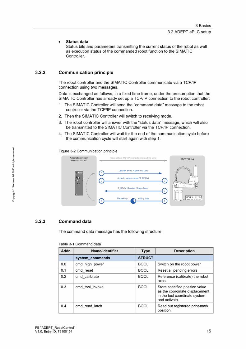
3.2.2 Communication principle
The robot controller and the SIMATIC Controller communicate via a TCP/IP connection using two messages. Data is exchanged as follows, in a fixed time frame, under the presumption that the SIMATIC Controller has already set up a TCP/IP connection to the robot controller: 1. The SIMATIC Controller will send the “command data” message to the robot
controller via the TCP/IP connection. 2. Then the SIMATIC Controller will switch to receiving mode. 3. The robot controller will answer with the “status data” message, which will also
be transmitted to the SIMATIC Controller via the TCP/IP connection. 4. The SIMATIC Controller will wait for the end of the communication cycle before
the communication cycle will start again with step 1. Figure 3-2 Communication principle
Automation systemSIMATIC S7-300 ADEPT RobotPrecondition: TCP/IP connection is ready to send
1
2
T_SEND: Send “Command Data“
Activate receive mode (T_RECV)
3T_RECV: Receive “Status Data“
44Remaining waiting time
2
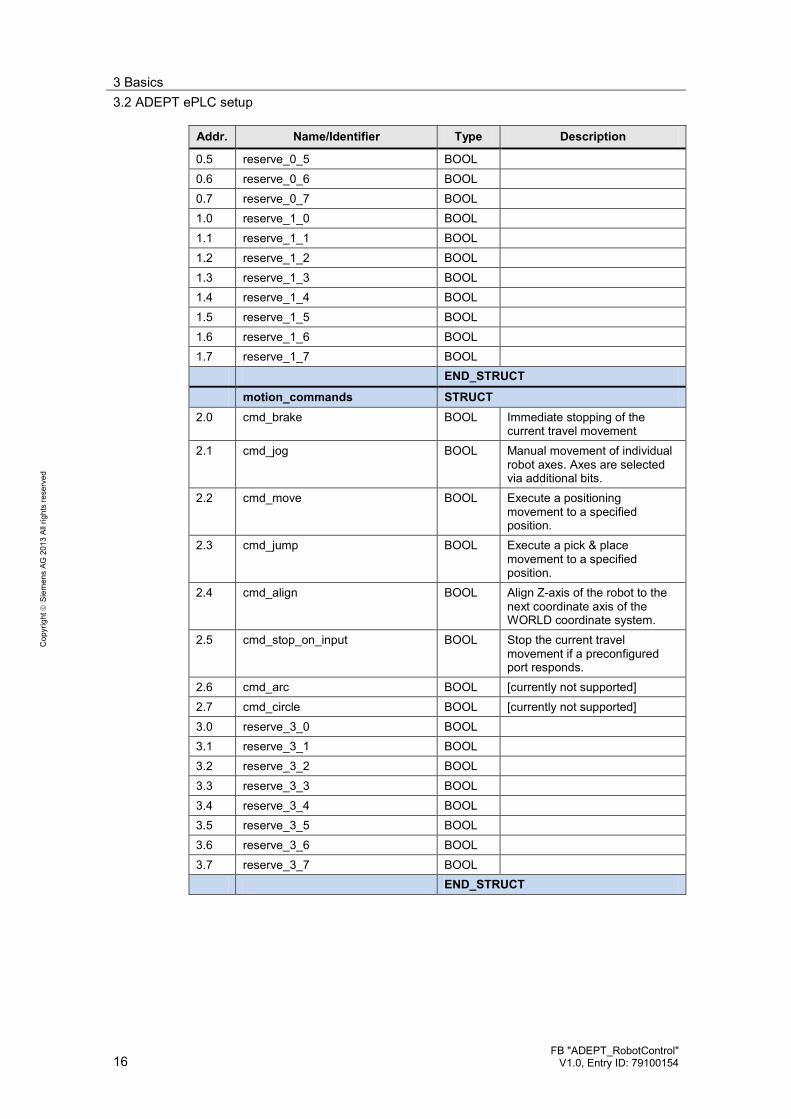
3.2.3 Command data
The command data message has the following structure: Table 3-1 Command data
Addr. Name/Identifier Type Description
system_commands STRUCT
0.0 cmd_high_power BOOL Switch on the robot power 0.1 cmd_reset BOOL Reset all pending errors 0.2 cmd_calibrate BOOL Reference (calibrate) the robot
axes 0.3 cmd_tool_invoke BOOL Store specified position value
as the coordinate displacement in the tool coordinate system and activate.
0.4 cmd_read_latch BOOL Read out registered print-mark position.
3 Basics 3.2 ADEPT ePLC setup
16 FB "ADEPT_RobotControl"
V1.0, Entry ID: 79100154
Cop
yrig
ht
Sie
men
s AG
201
3 Al
l rig
hts
rese
rved
Addr. Name/Identifier Type Description
0.5 reserve_0_5 BOOL
0.6 reserve_0_6 BOOL
0.7 reserve_0_7 BOOL
1.0 reserve_1_0 BOOL
1.1 reserve_1_1 BOOL
1.2 reserve_1_2 BOOL
1.3 reserve_1_3 BOOL
1.4 reserve_1_4 BOOL
1.5 reserve_1_5 BOOL
1.6 reserve_1_6 BOOL
1.7 reserve_1_7 BOOL
END_STRUCT
motion_commands STRUCT
2.0 cmd_brake BOOL Immediate stopping of the current travel movement
2.1 cmd_jog BOOL Manual movement of individual robot axes. Axes are selected via additional bits.
2.2 cmd_move BOOL Execute a positioning movement to a specified position.
2.3 cmd_jump BOOL Execute a pick & place movement to a specified position.
2.4 cmd_align BOOL Align Z-axis of the robot to the next coordinate axis of the WORLD coordinate system.
2.5 cmd_stop_on_input BOOL Stop the current travel movement if a preconfigured port responds.
2.6 cmd_arc BOOL [currently not supported] 2.7 cmd_circle BOOL [currently not supported] 3.0 reserve_3_0 BOOL
3.1 reserve_3_1 BOOL
3.2 reserve_3_2 BOOL
3.3 reserve_3_3 BOOL
3.4 reserve_3_4 BOOL
3.5 reserve_3_5 BOOL
3.6 reserve_3_6 BOOL
3.7 reserve_3_7 BOOL
END_STRUCT

3 Basics 3.2 ADEPT ePLC setup
FB "ADEPT_RobotControl" V1.0, Entry ID: 79100154 17
Cop
yrig
ht
Sie
men
s AG
201
3 Al
l rig
hts
rese
rved
Addr. Name/Identifier Type Description
motion_qualifiers STRUCT
4.0 relative_move BOOL 0 = Interpretation of the specified position as absolute target position 1 = Interpretation of the specified position as relative target position
4.1 joint_coordinates BOOL 0 = movement in the WORLD coordinate system 1 = movement in the JOINT coordinate system
4.2 straightline_move BOOL 0 = movement axis-interpolated 1 = movement on a straight line
4.3 approach_at_absolute BOOL 0 = Interpretation of the specified retraction height as a relative value. 1 = Interpretation of the specified retraction height as the absolute height.
4.4 nonull BOOL 0 = Exact approach of the end points of the specified movement 1 = Blending of two movements
4.5 coarse_nulling BOOL 0 = Positioning in the approximate range 1 = Positioning in the precise range
4.6 single_turn BOOL 0 = Allow multiple turns of the axis of revolution 1 = Allow only one single turn of the axis of revolution
4.7 reserve_4_7 BOOL 5.0 righty_configuration BOOL 0 =Arm alignment to the left
1 =Arm alignment to the right 5.1 below_configuration BOOL 0 =Arm alignment at the top
1 =Arm alignment at the bottom 5.2 flip_configuration BOOL 0 =Arm alignment not flipped
1 =Arm alignment flipped 5.3 relative_to_pallet_frame BOOL 0 = No application of settings for
pallet/frame 1 = Application of settings for pallet/frame
5.4 reserve_5_4 BOOL 5.5 reserve_5_5 BOOL 5.6 reserve_5_6 BOOL 5.7 reserve_5_7 BOOL END_STRUCT
jog_mode_qualifiers STRUCT
6.0 jog_world_mode BOOL Manual travel movement in WORLD coordinate system

3 Basics 3.2 ADEPT ePLC setup
18 FB "ADEPT_RobotControl"
V1.0, Entry ID: 79100154
Cop
yrig
ht
Sie
men
s AG
201
3 Al
l rig
hts
rese
rved
Addr. Name/Identifier Type Description
6.1 jog_tool_mode BOOL Manual travel movement in TOOL coordinate system
6.2 jog_joint_mode BOOL Manual travel movement in JOINT coordinate system
6.3 jog_free_mode BOOL Remove axis for manual travel movement from the controller
6.4 reserve_6_4 BOOL 6.5 reserve_6_5 BOOL 6.6 reserve_6_6 BOOL 6.7 reserve_6_7 BOOL 7.0 reserve_7_0 BOOL 7.1 reserve_7_1 BOOL 7.2 reserve_7_2 BOOL 7.3 reserve_7_3 BOOL 7.4 reserve_7_4 BOOL 7.5 reserve_7_5 BOOL 7.6 reserve_7_6 BOOL 7.7 reserve_7_7 BOOL 8.0 jog_joint_1_or_x_PLUS BOOL Manually moving axis 1/X in
plus direction 8.1 jog_joint_2_or_y_PLUS BOOL Manually moving axis 2/Y in
plus direction 8.2 jog_joint_3_or_z_PLUS BOOL Manually moving axis 3/Z in
plus direction 8.3 jog_joint_4_or_yaw_PLUS BOOL Manually moving axis 4/YAW in
plus direction 8.4 jog_joint_5_or_pitch_PLUS BOOL Manually moving axis 5/PITCH
in plus direction 8.5 jog_joint_6_or_roll_PLUS BOOL Manually moving axis 6/ROLL
in plus direction 8.6 reserve_8_6 BOOL 8.7 reserve_8_7 BOOL 9.0 jog_joint_1_or_x_MINUS BOOL Manually moving axis 1/X in
minus direction 9.1 jog_joint_2_or_y_ MINUS BOOL Manually moving axis 2/Y in
minus direction 9.2 jog_joint_3_or_z_ MINUS BOOL Manually moving axis 3/Z in
minus direction 9.3 jog_joint_4_or_yaw_ MINUS BOOL Manually moving axis 4/YAW in
minus direction 9.4 jog_joint_5_or_pitch_ MINUS BOOL Manually moving axis 5/PITCH
in minus direction 9.5 jog_joint_6_or_roll_ MINUS BOOL Manually moving axis 6/ROLL
in minus direction 9.6 reserve_9_6 BOOL 9.7 reserve_9_7 BOOL END_STRUCT

3 Basics 3.2 ADEPT ePLC setup
FB "ADEPT_RobotControl" V1.0, Entry ID: 79100154 19
Cop
yrig
ht
Sie
men
s AG
201
3 Al
l rig
hts
rese
rved
Addr. Name/Identifier Type Description
motion_parameters STRUCT
10 speed INT Absolute value of the speed of movement
12 acceleration INT Absolute value of the acceleration of movement
14 deceleration INT Absolute value of the deceleration of movement
16 acceleration_profile INT 0 = Trapezoidal movement profile 1 = S-shaped moving profile
18 speed_limit INT
20 pallet_index INT Number of the required “pallet index” as the target position
22 approach_height REAL Retraction height for the pick-and-place movement
26 reserve_26 REAL END_STRUCT
location_data STRUCT
30 X REAL X position 34 Y REAL Y position 38 Z REAL Z position 42 Yaw REAL Yaw angle 46 Pitch REAL Pitch angle 50 Roll REAL Roll angle END_STRUCT
location_2_data STRUCT
54 X REAL X position 58 Y REAL Y position 62 Z REAL Z position 66 Yaw REAL Yaw angle 70 Pitch REAL Pitch angle 74 Roll REAL Roll angle END_STRUCT
pallet STRUCT
pallet_origin STRUCT
78 X REAL X position 82 Y REAL Y position 86 Z REAL Z position 90 Yaw REAL Yaw angle 94 Pitch REAL Pitch angle 98 Roll REAL Roll angle END_STRUCT pallet_1st_row_location STRUCT
102 X REAL X position 106 Y REAL Y position

3 Basics 3.2 ADEPT ePLC setup
20 FB "ADEPT_RobotControl"
V1.0, Entry ID: 79100154
Cop
yrig
ht
Sie
men
s AG
201
3 Al
l rig
hts
rese
rved
Addr. Name/Identifier Type Description
110 Z REAL Z position 114 Yaw REAL Yaw angle 118 Pitch REAL Pitch angle 122 Roll REAL Roll angle END_STRUCT pallet_last_row_location STRUCT
126 X REAL X position 130 Y REAL Y position 134 Z REAL Z position 138 Yaw REAL Yaw angle 142 Pitch REAL Pitch angle 146 Roll REAL Roll angle END_STRUCT
150 pallet_positions_1st_row INT Number of positions in the first row of the pallet
152 pallet_number_of_rows INT Number of rows on the pallet 154 pallet_configuration INT Configuration of positions on
the pallet (0...4) 156 pallet_s_traversal INT 0 = Position configuration
always starting from one side 1 = S-Shaped configuration of positions
END_STRUCT
output_signals STRUCT
158.0 out_signal_1 BOOL XDIO output 158.1 out_signal_2 BOOL XDIO output 158.2 out_signal_3 BOOL XDIO output 158.3 out_signal_4 BOOL XDIO output 158.4 out_signal_5 BOOL XDIO output 158.5 out_signal_6 BOOL XDIO output 158.6 out_signal_7 BOOL XDIO output 158.7 out_signal_8 BOOL XDIO output 158.0 out_signal_3001 BOOL Solenoid output 159.1 out_signal_3002 BOOL Solenoid output 159.2 out_signal_3003 BOOL Solenoid output 159.3 out_signal_3004 BOOL Solenoid output 159.4 reserve_159_4 BOOL 159.5 reserve_159_5 BOOL 159.6 reserve_159_6 BOOL 159.7 reserve_159_7 BOOL END_STRUCT
vision STRUCT
commands STRUCT
160.0 vis_sequence_start BOOL Start vision sequence
3 Basics 3.2 ADEPT ePLC setup
FB "ADEPT_RobotControl" V1.0, Entry ID: 79100154 21
Cop
yrig
ht
Sie
men
s AG
201
3 Al
l rig
hts
rese
rved
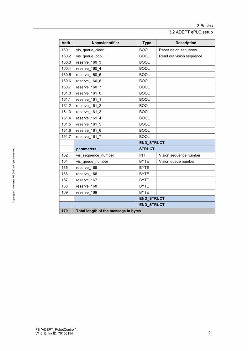
Addr. Name/Identifier Type Description
160.1 vis_queue_clear BOOL Reset vision sequence
160.2 vis_queue_pop BOOL Read out vision sequence 160.3 reserve_160_3 BOOL 160.4 reserve_160_4 BOOL 160.5 reserve_160_5 BOOL 160.6 reserve_160_6 BOOL 160.7 reserve_160_7 BOOL 161.0 reserve_161_0 BOOL 161.1 reserve_161_1 BOOL 161.2 reserve_161_2 BOOL 161.3 reserve_161_3 BOOL 161.4 reserve_161_4 BOOL 161.5 reserve_161_5 BOOL 161.6 reserve_161_6 BOOL 161.7 reserve_161_7 BOOL END_STRUCT
parameters STRUCT
162 vis_sequence_number INT Vision sequence number 164 vis_queue_number BYTE Vision queue number 165 reserve_165 BYTE 166 reserve_166 BYTE 167 reserve_167 BYTE 168 reserve_168 BYTE 169 reserve_169 BYTE END_STRUCT
END_STRUCT 170 Total length of the message in bytes

3 Basics 3.2 ADEPT ePLC setup
22 FB "ADEPT_RobotControl"
V1.0, Entry ID: 79100154
Cop
yrig
ht
Sie
men
s AG
201
3 Al
l rig
hts
rese
rved
3.2.4 Status data
The status data message has the following structure: Table 3-2 Status data
Addr. Name/Identifier Type Description
system_state STRUCT 0.0 system_heartbeat BOOL Toggle bit that is inverted with
every robot position update. 0.1 power_state BOOL 0 = Robot power off
1 = Robot power on 0.2 power_ready_state BOOL Robot is ready for switch-on
(key on the Adept panel is flashing)
0.3 system_initalized_state BOOL Robot controller re-initialized 0.4 emergency_stop_state BOOL The robot is in emergency stop
status 0.5 fault_state BOOL The robot is in fault status 0.6 calibrated_state BOOL Referencing of robot axes is
completed 0.7 command_execution_state BOOL Command detected and being
processed - reset with undoing command
1.0 read_latch_state BOOL Print-mark position was read. Configured port has released.
1.1 ace_control_mode BOOL The robot is currently controlled via the Adept engineering software.
1.2 reserve_1_2 BOOL 1.3 reserve_1_3 BOOL 1.4 reserve_1_4 BOOL 1.5 reserve_1_5 BOOL 1.6 reserve_1_6 BOOL 1.7 reserve_1_7 BOOL 2 state_robot_overall INT Robot status STATE(1)
For more information please refer to the manufacturer’s documentation.
4 state_robot_motion INT Robot status STATE(2) For more information please refer to the manufacturer’s documentation.
6 state_manual_control_mode INT Robot status STATE(3) For more information please refer to the manufacturer’s documentation.
8 state_hardware INT Robot status STATE(4) For more information please refer to the manufacturer’s documentation.

3 Basics 3.2 ADEPT ePLC setup
FB "ADEPT_RobotControl" V1.0, Entry ID: 79100154 23
Cop
yrig
ht
Sie
men
s AG
201
3 Al
l rig
hts
rese
rved
Addr. Name/Identifier Type Description
10 state_switch INT Robot status STATE(5) For more information please refer to the manufacturer’s documentation.
12 state_current_motion INT Robot status STATE(10) For more information please refer to the manufacturer’s documentation.
14 state_power_light INT Robot status STATE(30) For more information please refer to the manufacturer’s documentation.
END_STRUCT
motion_state STRUCT
16.0 in_position_state BOOL Positioning completed. Target position reached.
16.1 motion_state BOOL Robot movement active 16.2 brake_state BOOL Command detected and being
processed - reset with finishing command execution
16.3 stop_on_input_state BOOL Command detected and being processed - reset with finishing command execution
16.4 tool_mode_state BOOL The current robot movement is executed in the TOOL coordinate system
16.5 reserve_16_5 16.6 reserve_16_6 16.7 reserve_16_7 17.0 jog_mode_state BOOL The robot is currently moved in
jog mode. 17.1 world_jog_mode_state BOOL The current robot movement is
executed in the WORLD coordinate system
17.2 tool_ jog_mode_state BOOL The current robot movement is executed in the TOOL coordinate system
17.3 joint_ jog_mode_state BOOL The current robot movement is executed in the JOINT coordinate system
17.4 free_ jog_mode_state BOOL Robot axes were removed from the controller for manual movement.
17.5 reserve_17_5 BOOL 17.6 reserve_17_6 BOOL 17.7 reserve_17_7 BOOL 18.0 righty_configuration BOOL 0 =Arm alignment to the left
1 =Arm alignment to the right 18.1 below_configuration BOOL 0 =Arm alignment at the top
1 =Arm alignment at the bottom
3 Basics 3.2 ADEPT ePLC setup
24 FB "ADEPT_RobotControl"
V1.0, Entry ID: 79100154
Cop
yrig
ht
Sie
men
s AG
201
3 Al
l rig
hts
rese
rved
Addr. Name/Identifier Type Description
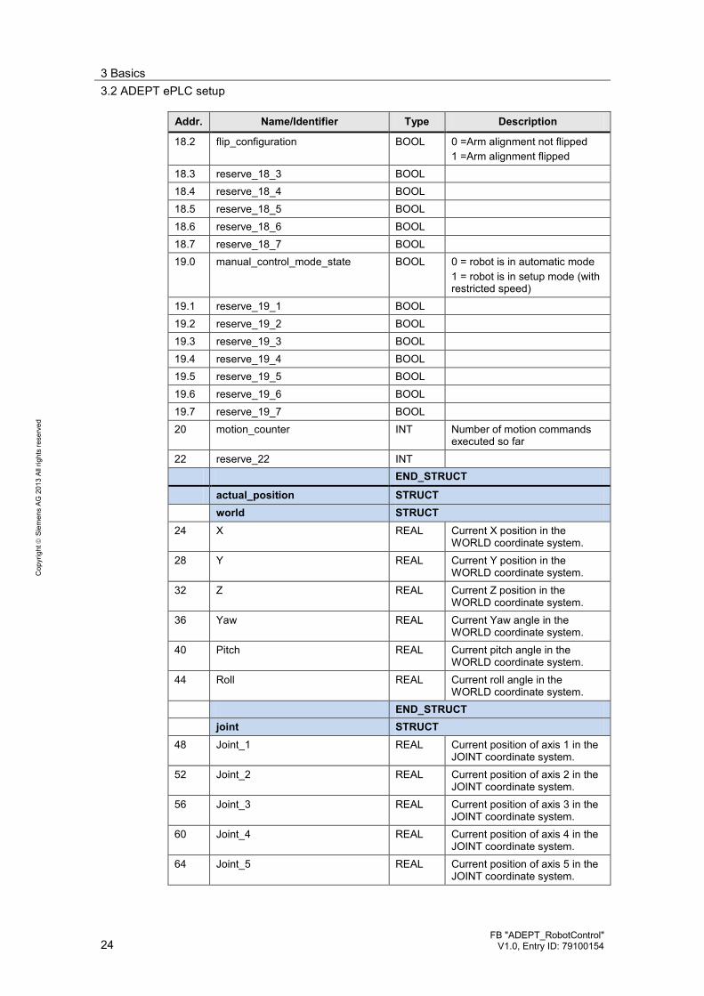
18.2 flip_configuration BOOL 0 =Arm alignment not flipped 1 =Arm alignment flipped
18.3 reserve_18_3 BOOL 18.4 reserve_18_4 BOOL 18.5 reserve_18_5 BOOL 18.6 reserve_18_6 BOOL 18.7 reserve_18_7 BOOL 19.0 manual_control_mode_state BOOL 0 = robot is in automatic mode
1 = robot is in setup mode (with restricted speed)
19.1 reserve_19_1 BOOL 19.2 reserve_19_2 BOOL 19.3 reserve_19_3 BOOL 19.4 reserve_19_4 BOOL 19.5 reserve_19_5 BOOL 19.6 reserve_19_6 BOOL 19.7 reserve_19_7 BOOL 20 motion_counter INT Number of motion commands
executed so far 22 reserve_22 INT END_STRUCT
actual_position STRUCT
world STRUCT
24 X REAL Current X position in the WORLD coordinate system.
28 Y REAL Current Y position in the WORLD coordinate system.
32 Z REAL Current Z position in the WORLD coordinate system.
36 Yaw REAL Current Yaw angle in the WORLD coordinate system.
40 Pitch REAL Current pitch angle in the WORLD coordinate system.
44 Roll REAL Current roll angle in the WORLD coordinate system.
END_STRUCT
joint STRUCT
48 Joint_1 REAL Current position of axis 1 in the JOINT coordinate system.
52 Joint_2 REAL Current position of axis 2 in the JOINT coordinate system.
56 Joint_3 REAL Current position of axis 3 in the JOINT coordinate system.
60 Joint_4 REAL Current position of axis 4 in the JOINT coordinate system.
64 Joint_5 REAL Current position of axis 5 in the JOINT coordinate system.

3 Basics 3.2 ADEPT ePLC setup
FB "ADEPT_RobotControl" V1.0, Entry ID: 79100154 25
Cop
yrig
ht
Sie
men
s AG
201
3 Al
l rig
hts
rese
rved
Addr. Name/Identifier Type Description
68 Joint_6 REAL Current position of axis 6 in the JOINT coordinate system.
END_STRUCT
END_STRUCT
latch_position STRUCT
world STRUCT
72 X REAL For more information please refer to ADEPT documentation. 76 Y REAL
80 Z REAL 84 Yaw REAL 88 Pitch REAL 92 Roll REAL END_STRUCT
END_STRUCT
pallet_relative_coordinates STRUCT
world STRUCT
96 X REAL For more information please refer to ADEPT documentation. 100 Y REAL
104 Z REAL 108 Yaw REAL 112 Pitch REAL 116 Roll REAL END_STRUCT
END_STRUCT
input_singals STRUCT
120.0 input_1001 BOOL XDIO Input 1001 120.1 input_1002 BOOL XDIO Input 1002 120.2 input_1003 BOOL XDIO Input 1003 120.3 input_1004 BOOL XDIO Input 1004 120.4 input_1005 BOOL XDIO Input 1005 120.5 input_1006 BOOL XDIO Input 1006 120.6 input_1007 BOOL XDIO Input 1007 120.7 input_1008 BOOL XDIO Input 1008 121.0 input_1009 BOOL XDIO Input 1009 121.1 input_1010 BOOL XDIO Input 1010 121.2 input_1011 BOOL XDIO Input 1011 121.3 input_1012 BOOL XDIO Input 1012 121.4 soft_signal_2001 BOOL eV+ soft signal 2001 121.5 soft_signal_2002 BOOL eV+ soft signal 2002 121.6 soft_signal_2003 BOOL eV+ soft signal 2003 121.7 soft_signal_2004 BOOL eV+ soft signal 2004 END_STRUCT

3 Basics 3.2 ADEPT ePLC setup
26 FB "ADEPT_RobotControl"
V1.0, Entry ID: 79100154
Cop
yrig
ht
Sie
men
s AG
201
3 Al
l rig
hts
rese
rved
Addr. Name/Identifier Type Description
error_message STRUCT
122 error_number INT Error number. Positive or negative values can be output here.
124 reserve_124 INT 126 maximum_length BYTE In the SIMATIC, data can be
interpreted as SIMATIC string and processed. SIMATIC String = 1 byte total length (here 80) / 1 byte number of characters / 80 bytes character.
127 actual_length BYTE 128 data ARRAY
[1..80] OF CHAR
END_STRUCT
vision STRUCT vis_state STRUCT
208.0 vis_sequence_started BOOL For more information please refer to ADEPT documentation. 208.1 vis_queue_cleared BOOL
208.2 vis_queue_popped BOOL 208.3 vis_results_valid BOOL 208.4 vis_system_online BOOL 208.5 reserve_208_5 BOOL 208.6 reserve_208_6 BOOL 208.7 reserve_208_7 BOOL 209.0 reserve_209_0 BOOL 209.1 reserve_209_1 BOOL 209.2 reserve_209_2 BOOL 209.3 reserve_209_3 BOOL 209.4 reserve_209_4 BOOL 209.5 reserve_209_5 BOOL 209.6 reserve_209_6 BOOL 209.7 reserve_209_7 BOOL 210 vis_sequence_number INT For more information please
refer to ADEPT documentation. 212 vis_sequence_state BYTE 213 vis_instances_found BYTE 214 vis_results_queue_number BYTE 215 reserve_215 BYTE END_STRUCT
vis_queue_size STRUCT
216 Vision_queue_0 BYTE For more information please refer to ADEPT documentation. 217 Vision_queue_1 BYTE
218 Vision_queue_2 BYTE 219 Vision_queue_3 BYTE 220 Vision_queue_4 BYTE 221 Vision_queue_5 BYTE 222 Vision_queue_6 BYTE

3 Basics 3.2 ADEPT ePLC setup
FB "ADEPT_RobotControl" V1.0, Entry ID: 79100154 27
Cop
yrig
ht
Sie
men
s AG
201
3 Al
l rig
hts
rese
rved
Addr. Name/Identifier Type Description
223 Vision_queue_7 BYTE END_STRUCT vis_result STRUCT
224 X REAL For more information please refer to ADEPT documentation. 228 Y REAL
232 Z REAL 236 Yaw REAL 240 Pitch REAL 244 Roll REAL END_STRUCT
END_STRUCT 248 Total length of the message in bytes

4 Function Mechanisms 4.1 POWER - switching the power on/off
28 FB "ADEPT_RobotControl"
V1.0, Entry ID: 79100154
Cop
yrig
ht
Sie
men
s AG
201
3 Al
l rig
hts
rese
rved
4 Function Mechanisms The functions described in the following chapters are stored in the function block for controlling the robot functions which is introduced in this application. They can easily be executed through the function block. In the following, the controlling of these functions via the ADEPT ePLC data interface in the robot controller, which is executed by the function block in the SIMATIC controller, will be described briefly.
4.1 POWER - switching the power on/off
4.1.1 Functionality
Switching the power at the robot on and off to enable the movement of the robot axes.
4.1.2 ADEPT ePLC signals involved
The following signals of the ADEPT ePLC data interface will be used for realizing this function. Table 4-1ADEPT ePLC signals involved
Addr. Name/Identifier Type
Command data 0.0 system_commands.cmd_high_power BOOL 0.1 system_commands.cmd_reset BOOL Status data
0.1 system_state.power_state BOOL 0.4 system_state.emergency_stop_state BOOL 0.5 system_state.fault_state BOOL 0.7 system_state.command_execution_state BOOL
4.1.3 Signal sequence for function control
The function is controlled in the robot controller as follows:
Switch on power Table 4-2 Signal sequence for function control
No. Functionality Note/Remark
1. Check whether the robot is in emergency stop state.
If the robot is in emergency stop state, the function will branch into the error handling routine.
2. Reset the robot in order to acknowledge any pending errors.

4 Function Mechanisms 4.2 CALIBRATE - Reference the robot axes
FB "ADEPT_RobotControl" V1.0, Entry ID: 79100154 29
Cop
yrig
ht
Sie
men
s AG
201
3 Al
l rig
hts
rese
rved
No. Functionality Note/Remark
3. Switch on the power at the robot. If there is a robot error or if a robot error occurs when the power is switched on, the function will branch into the error handling routine.
4. Power will stay on at the robot as long as the “cmd_high_power” command is set.
Switch off power Table 4-3 Signal sequence for function control
No. Functionality Note/Remark
1. Switch off the power at the robot. If there is a robot error or if a robot error occurs when the power is switched off, the function will branch into the error handling routine.
2. Power will stay off at the robot until the “cmd_high_power” command is set.
4.2 CALIBRATE - Reference the robot axes
4.2.1 Functionality
Calibrate or reference the robot axes. For this, the robot axes will perform a hardly noticeable movement around the current position.
4.2.2 ADEPT ePLC signals involved
The following signals of the ADEPT ePLC data interface will be used for realizing this function. Table 4-4ADEPT ePLC signals involved
Addr. Name/Identifier Type
Command data 0.2 system_commands.cmd_calibrate BOOL Status data
0.5 system_state.fault_state BOOL 0.6 system_state.calibrated_state BOOL 0.7 system_state.command_execution_state BOOL
4.2.3 Signal sequence for function control
The function is controlled in the robot controller as follows:

4 Function Mechanisms 4.3 RESET - Reset errors at the robot
30 FB "ADEPT_RobotControl"
V1.0, Entry ID: 79100154
Cop
yrig
ht
Sie
men
s AG
201
3 Al
l rig
hts
rese
rved
Table 4-5 Signal sequence for function control
No. Functionality Note/Remark
1. Check whether the robot axes have already been calibrated.
If the robot axes have already been calibrated, the function will not be executed at the robot.
2. Trigger the function for calibrating the robot axes.
If there is a robot error when the function is triggered, the function will branch into the error handling routine.
4.3 RESET - Reset errors at the robot
4.3.1 Functionality
Reset or acknowledge any error states pending at the robot or the robot controller.
4.3.2 ADEPT ePLC signals involved
The following signals of the ADEPT ePLC data interface will be used for realizing this function. Table 4-6ADEPT ePLC signals involved
Addr. Name/Identifier Type
Command data 0.1 system_commands.cmd_reset BOOL 0.2 system_commands.cmd_calibrate BOOL 0.3 system_commands.cmd_tool_invoke BOOL 0.4 system_commands.cmd_read_latch BOOL 2.0 motion_commands.cmd_brake BOOL 2.1 motion_commands.cmd_jog BOOL 2.2 motion_commands.cmd_move BOOL 2.3 motion_commands.cmd_jump BOOL 2.4 motion_commands.cmd_align BOOL 2.5 motion_commands.cmd_stop_on_input BOOL 2.6 motion_commands.cmd_arc BOOL 2.7 motion_commands.cmd_circle BOOL Status data
0.7 system_state.command_execution_state BOOL 0.5 system_state.fault_state BOOL
4.3.3 Signal sequence for function control
The function is controlled in the robot controller as follows:

4 Function Mechanisms 4.4 BRAKE - Immediately stop robot movement
FB "ADEPT_RobotControl" V1.0, Entry ID: 79100154 31
Cop
yrig
ht
Sie
men
s AG
201
3 Al
l rig
hts
rese
rved
Table 4-7 Signal sequence for function control
No. Functionality Note/Remark
1. Reset any currently pending system commands and travel commands.
2. Trigger the function for acknowledging the pending error states at the robot.
4.4 BRAKE - Immediately stop robot movement
4.4.1 Functionality
Stop a robot movement currently performed by the robot, or inhibit the triggering of a new robot movement.
4.4.2 ADEPT ePLC signals involved
The following signals of the ADEPT ePLC data interface are used for realizing this function. Table 4-8 ADEPT ePLC signals involved
Addr. Name/Identifier Type
Command data 2.0 motion_commands.cmd_brake BOOL Status data
16.2 motion_state.brake_state BOOL
4.4.3 Signal sequence for function control
The function is controlled in the robot controller as follows: Table 4-9 Signal sequence for function control
No. Functionality Note/Remark
1. Trigger the function for stopping the current robot movement, or for inhibiting further robot movements.
The function will stay active as long as the input at the function block is set.
2. Further robot movements will be inhibited as long as the order “cmd_brake” command is set.
3. Complete the function by resetting the input at the function block.
Robot movements are now enabled again. Any error states occurred due to the stopping action might have to be acknowledged before the next robot movement.

4 Function Mechanisms 4.5 JOG - Move axes in jog mode
32 FB "ADEPT_RobotControl"
V1.0, Entry ID: 79100154
Cop
yrig
ht
Sie
men
s AG
201
3 Al
l rig
hts
rese
rved
4.5 JOG - Move axes in jog mode
4.5.1 Functionality
Move the individual robot axes in jog mode. The direction of travel and the required axis are defined by selecting the corresponding command.
4.5.2 ADEPT ePLC signals involved
The following signals of the ADEPT ePLC data interface will be used for realizing this function. Table 4-10 ADEPT ePLC signals involved
Addr. Name/Identifier Type
Command data 2.1 motion_commands.cmd_jog BOOL 6.0 jog_mode_qualifiers.jog_world_mode BOOL 6.1 jog_mode_qualifiers.jog_tool_mode BOOL 6.2 jog_mode_qualifiers.jog_joint_mode BOOL 6.3 jog_mode_qualifiers.jog_free_mode BOOL 8.0 jog_mode_qualifiers.jog_joint_1_or_x_PLUS BOOL 8.1 jog_mode_qualifiers.jog_joint_2_or_y_PLUS BOOL 8.2 jog_mode_qualifiers.jog_joint_3_or_z_PLUS BOOL 8.3 jog_mode_qualifiers.jog_joint_4_or_yaw_PLUS BOOL 8.4 jog_mode_qualifiers.jog_joint_5_or_pit_PLUS BOOL 8.5 jog_mode_qualifiers.jog_joint_6_or_rol_PLUS BOOL 9.0 jog_mode_qualifiers.jog_joint_1_or_x_MINUS BOOL 9.1 jog_mode_qualifiers.jog_joint_2_or_y_ MINUS BOOL 9.2 jog_mode_qualifiers.jog_joint_3_or_z_ MINUS BOOL 9.3 jog_mode_qualifiers.jog_joint_4_or_yaw_ MINUS BOOL 9.4 jog_mode_qualifiers.jog_joint_5_or_pit_ MINUS BOOL 9.5 jog_mode_qualifiers.jog_joint_6_or_rol_ MINUS BOOL 10 motion_parameters.speed INT 12 motion_parameters.acceleration INT 14 motion_parameters.deceleration INT 16 motion_parameters.acceleration_profile INT 18 motion_parameters.speed_limit INT Status data
17.0 motion_state.jog_mode_state BOOL
4.5.3 Signal sequence for function control
The function is controlled in the robot controller as follows:

4 Function Mechanisms 4.6 MOVE - Perform sequences of movements
FB "ADEPT_RobotControl" V1.0, Entry ID: 79100154 33
Cop
yrig
ht
Sie
men
s AG
201
3 Al
l rig
hts
rese
rved
Table 4-11 Signal sequence for function control
No. Functionality Note/Remark
1. Apply the coordinate system required for jog mode.
Usually jog mode (JOG) is carried out in the axis coordinate system (JOINT) or in the Cartesian coordinate system (WORLD).
2. Apply the dynamic values required for jog mode.
For security reasons, individual dynamic values will be specified for jog mode (JOG).
3. Triggering the jog mode (JOG) for the axes selected.
4. The axis movements will be performed as long as the jog mode is selected for each axis.
5. Reset the jog mode (JOG).
4.6 MOVE - Perform sequences of movements
4.6.1 Functionality
Perform a coordinated movement or a sequence of movements, which may involve all axes of the robot and which may be performed using the kinematic transformation of the robot controller.
4.6.2 ADEPT ePLC signals involved
The following signals of the ADEPT ePLC data interface will be used for realizing this function. Table 4-12 ADEPT ePLC signals involved
Addr. Name/Identifier Type
Command data 2.1 motion_commands.cmd_jog BOOL 2.2 motion_commands.cmd_move BOOL 2.3 motion_commands.cmd_jump BOOL 2.4 motion_commands.cmd_align BOOL 2.5 motion_commands.cmd_stop_on_input BOOL 2.6 motion_commands.cmd_arc BOOL 2.7 motion_commands.cmd_circle BOOL 4.0 motion_qualifiers.relative_move BOOL 4.1 motion_qualifiers.joint_coordinates BOOL 4.2 motion_qualifiers.straightline_move BOOL 4.3 motion_qualifiers.approach_at_absolute BOOL 4.4 motion_qualifiers.nonull BOOL 4.5 motion_qualifiers.coarse_nulling BOOL 4.6 motion_qualifiers.single_turn BOOL 5.0 motion_qualifiers.righty_configuration BOOL

4 Function Mechanisms 4.6 MOVE - Perform sequences of movements
34 FB "ADEPT_RobotControl"
V1.0, Entry ID: 79100154
Cop
yrig
ht
Sie
men
s AG
201
3 Al
l rig
hts
rese
rved
Addr. Name/Identifier Type
5.1 motion_qualifiers.below_configuration BOOL 5.2 motion_qualifiers.flip_configuration BOOL 5.3 motion_qualifiers.relative_to_pallet_frame BOOL 10 motion_parameters.speed INT 12 motion_parameters.acceleration INT 14 motion_parameters.deceleration INT 16 motion_parameters.acceleration_profile INT 18 motion_parameters.speed_limit INT 20 motion_parameters.pallet_index INT 22 motion_parameters.approach_height REAL 30 location_data.X REAL 34 location_data.Y REAL 38 location_data.Z REAL 42 location_data.Yaw REAL 46 location_data.Pitch REAL 50 location_data.Roll REAL Status data
0.7 system_state.command_execution_state BOOL 16.0 motion_state.in_position_state BOOL
4.6.3 Signal sequence for function control
The function is controlled in the robot controller as follows: Table 4-13 Signal sequence for function control
No. Functionality Note/Remark
1. Reset any currently pending travel commands.
2. Apply the movement criteria for performing the movement.
3. Apply the dynamic values required for the movement.
For security reasons, individual dynamic values will be specified for the coordinated movement of the robot.
4. Apply the target position specified for the movement.
For security reasons, the target position is specified through different parameters in the axis coordinate system (JOINT) and in the Cartesian coordinate system (WORLD). Parameters are selected via the motion qualifier “motion_qualifiers.joint_coordinates”.
5. Trigger the travel movement.

4 Function Mechanisms 4.6 MOVE - Perform sequences of movements
FB "ADEPT_RobotControl" V1.0, Entry ID: 79100154 35
Cop
yrig
ht
Sie
men
s AG
201
3 Al
l rig
hts
rese
rved
No. Functionality Note/Remark
6. If, during an active travel movement, a new travel command is issued, this command will be added to the currently processed travel movement.
7. If no new travel command is issued, the current movement will be completed and then the robot axes will be stopped.

5 Installation 5.1 Hardware installation
36 FB "ADEPT_RobotControl"
V1.0, Entry ID: 79100154
Cop
yrig
ht
Sie
men
s AG
201
3 Al
l rig
hts
rese
rved
5 Installation 5.1 Hardware installation
For commissioning the application example the SIMATIC automation system must be connected to the Ethernet interface of the robot controller via the PROFINET/Ethernet interface. Figure 5-1 Hardware installation - wiring of the components
Robot Controller
SIMATIC Controller
Ethernet or PROFINET cable
Note In case the interfaces of the SIMATIC Controller and the robot controller are directly connected, the use of an Ethernet cross cable might be required.
5.2 Integrating the application into a STEP 7 project
This section describes how to integrate the application into an existing or a newly established STEP 7 project.
5.2.1 Copying the required blocks and sources
Copy the blocks listed in the table into your existing or newly established STEP 7 project. Table 5-1 Required blocks
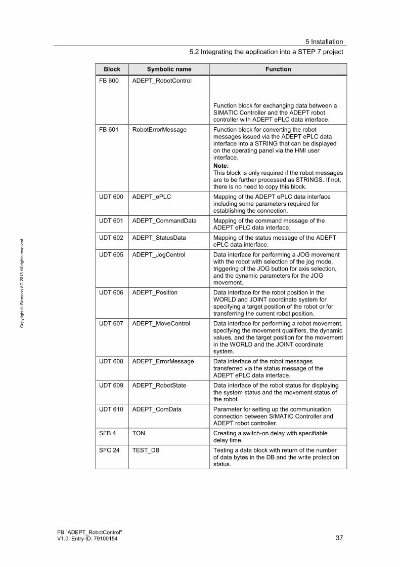
Block Symbolic name Function
FB 63 TSEND Function block working asynchronously, sending data through an existing communication connection.
FB 64 TRCV Function block working asynchronously, receiving data through an existing communication connection.
FB 65 TCON Function block working asynchronously, for setting up and establishing a communication connection.
FB 66 TDISCON Function block working asynchronously, for clearing a communication connection.
5 Installation 5.2 Integrating the application into a STEP 7 project
FB "ADEPT_RobotControl" V1.0, Entry ID: 79100154 37
Cop
yrig
ht
Sie
men
s AG
201
3 Al
l rig
hts
rese
rved
Block Symbolic name Function
FB 600 ADEPT_RobotControl Function block for exchanging data between a SIMATIC Controller and the ADEPT robot controller with ADEPT ePLC data interface.
FB 601 RobotErrorMessage Function block for converting the robot messages issued via the ADEPT ePLC data interface into a STRING that can be displayed on the operating panel via the HMI user interface. Note: This block is only required if the robot messages are to be further processed as STRINGS. If not, there is no need to copy this block.
UDT 600 ADEPT_ePLC Mapping of the ADEPT ePLC data interface including some parameters required for establishing the connection.
UDT 601 ADEPT_CommandData Mapping of the command message of the ADEPT ePLC data interface.
UDT 602 ADEPT_StatusData Mapping of the status message of the ADEPT ePLC data interface.
UDT 605 ADEPT_JogControl Data interface for performing a JOG movement with the robot with selection of the jog mode, triggering of the JOG button for axis selection, and the dynamic parameters for the JOG movement.
UDT 606 ADEPT_Position Data interface for the robot position in the WORLD and JOINT coordinate system for specifying a target position of the robot or for transferring the current robot position.
UDT 607 ADEPT_MoveControl Data interface for performing a robot movement, specifying the movement qualifiers, the dynamic values, and the target position for the movement in the WORLD and the JOINT coordinate system.
UDT 608 ADEPT_ErrorMessage Data interface of the robot messages transferred via the status message of the ADEPT ePLC data interface.
UDT 609 ADEPT_RobotState Data interface of the robot status for displaying the system status and the movement status of the robot.
UDT 610 ADEPT_ComData Parameter for setting up the communication connection between SIMATIC Controller and ADEPT robot controller.
SFB 4 TON Creating a switch-on delay with specifiable delay time.
SFC 24 TEST_DB Testing a data block with return of the number of data bytes in the DB and the write protection status.

5 Installation 5.2 Integrating the application into a STEP 7 project
38 FB "ADEPT_RobotControl"
V1.0, Entry ID: 79100154
Cop
yrig
ht
Sie
men
s AG
201
3 Al
l rig
hts
rese
rved
5.2.2 Compiling the SCL source of the function block (optional)
The FB 600 “ADEPT_RobotControl“ function block is written in the “STEP 7 SCL” high-level language for easier handling of data structures. The compiled block is available in the block folder of the STEP 7 project. In order to use the block in STEP 7 projects without the “SCL” option, it is sufficient to copy the compiled FB 600 “ADEPT_RobotControl” block from the block folder into the existing or newly created STEP 7 project. In case the “SCL” option has been installed in the SIMATIC Manager, the FB 600 “ADEPT_RobotControl” block can easily be changed and re-compiled.
5.2.3 Integrating the function block into a cyclic OB
In order to use the application in your STEP 7 project, call function block FB 600 “ADEPT_RobotControl” in a cyclically processed organization block, OB1 for example. If the robot messages from the status message of the ADEPT ePLC data interface are to be further processed as a STRING tags, by displaying them on a HMI user interface, for example, FB 601 “RobotErrorMessage” will also have to be called in a cyclically processed organization block, e.g. OB1. It is recommendable to call FB 601 “RobotErrorMessage” directly after FB 600 “ADEPT_RobotControl” and to transfer the data from port “RobotErrorMessage” of FB 600 “ADEPT_RobotControl” to port “RobotErrorMessage” of FB 601 “RobotErrorMessage”.
5.2.4 Using the HMI user interface
If the HMI user interface for FB 600 “ADEPT_RobotControl” is to be transferred to the STEP 7 project as well, the WinCC flexible project of the HMI user interface will also have to be transferred into your STEP 7 project and, if required, the tags of the HMI user interface will have to be reconnected with the instance block of FB 600 “ADEPT_RobotControl” via WinCC flexible project; in this example this would be DB 600 “idb_ADEPT_RobotControl”. This is how to proceed: • In the SIMATIC Manager, copy HMI object “SIMATIC MobilePanel 277” from
the application example into your STEP 7 project. • Open the copied HMI object in your STEP 7 project in WinCC flexible and
reconnect the tags of the HMI user interface to the instance block of FB 600 “ADEPT_RobotControl” in your STEP 7 project.
To reconnect the tags of the HMI user interface in the STEP 7 project, proceed as follows: After copying the HMI object into your STEP 7 project, open the HMI object via WinCC flexible. In the project tree, under “Communication > Tags”, you can see whether the connection of the tags to the controller, or the instance block of FB 600 “ADEPT_RobotControl”, is still active. If it is not, first check the connection to the HMI user interface to the controller via “Communication > Connections”. Here, if required, select the controller from your STEP 7 project. You can then select the function “Reconnect” via the context menu of the “Communication > Tags” tree object.

5 Installation 5.2 Integrating the application into a STEP 7 project
FB "ADEPT_RobotControl" V1.0, Entry ID: 79100154 39
Cop
yrig
ht
Sie
men
s AG
201
3 Al
l rig
hts
rese
rved
Figure 5-2 WinCC flexible – reconnecting tags
In the function dialog for reconnection, set the functions for reconnecting the tags as shown below. Definitely make sure that the option “Replace tag name with symbol name” is deselected. Otherwise the tag table of the HMI project might be renamed. Figure 5-3 Options for reconnecting symbols in WinCC flexible
Execute the function by clicking “OK”. After that, all tags should be reconnected with the controller.

6 Startup 6.1 Description of the function block interface
40 FB "ADEPT_RobotControl"
V1.0, Entry ID: 79100154
Cop
yrig
ht
Sie
men
s AG
201
3 Al
l rig
hts
rese
rved
6 Startup 6.1 Description of the function block interface
6.1.1 Block interface
FB 600“ADEPT_RobotControl“
ComData
ConnectBOOL
STRUCT
PowerBOOL
CalibrateBOOL
ResetBOOL
BrakeBOOL
JOGSTRUCT
MOVESTRUCT
Connected BOOL
PowerReady BOOL
PowerON BOOL
Calibrated BOOL
ResetDone BOOL
BrakeON BOOL
Jogging BOOL
Moving BOOL
NextMove BOOL
MoveDone BOOL
Error BOOL
ErrorID WORD
ActualPosition STRUCT
RobotErrorMessage STRUCT/STRING
Table 6-1 Function block interface
Parameter Data type Initial value Description
Input parameters
Connect BOOL False Communication with the robot controller is started through this parameter. The communication with the robot controller is active as long as the input is set.
ComData STRUCT Communication parameter for connection setup with the robot controller see next chapter
Power BOOL False Switching on the power at the robot. The robot power will stay on as long as the input is set. If necessary, due to fault conditions, the robot power may also be switched off by the robot controller.
Calibrate BOOL False Triggering the homing operation of the robot axes (with minimum axis movement). The homing operation will only be performed if the axes of the robot have not yet been referenced, or calibrated.

6 Startup 6.1 Description of the function block interface
FB "ADEPT_RobotControl" V1.0, Entry ID: 79100154 41
Cop
yrig
ht
Sie
men
s AG
201
3 Al
l rig
hts
rese
rved
Parameter Data type Initial value Description
Reset BOOL False Acknowledging any error messages pending at the robot controller and canceling any current commands within the function block.
Brake BOOL False Immediately stopping any travel movements of the robot. Further travel movements of the robot axis will be prevented as long as the input is set.
JOG STRUCT Parameter for performing the jog mode of the robot axes see next chapter
MOVE STRUCT Parameter for the performance of coordinated movements or a sequence of movements by the robot. see next chapter
Output parameters
Connected BOOL False The communication connection with the robot controller is set up. The robot can be influenced via the function block.
PowerReady BOOL False Robot is ready for switch-on. The robot power can be switched on by actuating the button at the robot operating panel.
PowerON BOOL False The power at the robot is switched on. The robot axes can now be moved.
Calibrated BOOL False The axes of the robot are referenced, or calibrated.
ResetDone BOOL False Any error messages pending at the robot controller were acknowledged.
BrakeON BOOL False All axes of the robot are stopped. No travel movements of the robot axis can be performed as long as the output is set.
Jogging BOOL False The robot axes are moved in jog mode.
Moving BOOL False The robot axes are moved through a coordinated movement.
NextMove BOOL False Another movement command for performing a sequence of movements can be issued via the “MOVE” input.

6 Startup 6.1 Description of the function block interface
42 FB "ADEPT_RobotControl"
V1.0, Entry ID: 79100154
Cop
yrig
ht
Sie
men
s AG
201
3 Al
l rig
hts
rese
rved
Parameter Data type Initial value Description
MoveDone BOOL False The current coordinated movement or sequence of movements is completed.
Error BOOL False Error at the function block. ErrorID WORD W#16#0 Error number for more detailed
specification of the error cause. see next chapter
ActualPosition STRUCT Current position of the robot axes in the axis coordinate system (JOINT) and in the Cartesian coordinate system (WORLD) see next chapter
RobotErrorMessage STRUCT Output of the robot controller messages see next chapter
DANGER
In case of danger, take additional measures for stopping the robot if the robot movements can no longer be influenced by the SIMATIC Controller.
6.1.2 “ComData” data structure
Table 6-2 “ComData” data structure
Parameter Data type Initial value Description
STRUCT
ID WORD W#16#5F Freely selectable communication ID that must be uniquely specified for each robot.
IP_Address ARRAY[1..6] OF BYTE IP_Address[1] BYTE B#16#0 IP address of the robot controller
in IPv4 format for setting up the communication connection. IP_Address[2] BYTE B#16#0
IP_Address[3] BYTE B#16#0 IP_Address[4] BYTE B#16#0 IP_Address[5] BYTE B#16#0 Not used. IP_Address[6] BYTE B#16#0 END_STRUCT LocalDevice_Type BYTE B#16#2 Identifier of the controller hardware
from which the robot is controlled. The setting options for this parameter correspond to the “local_device_id” parameter according to the UDT 65 for the “CONNECT” input of the “T_CON” block for setting up the connection.

6 Startup 6.1 Description of the function block interface
FB "ADEPT_RobotControl" V1.0, Entry ID: 79100154 43
Cop
yrig
ht
Sie
men
s AG
201
3 Al
l rig
hts
rese
rved
Parameter Data type Initial value Description
Port DINT 46555 Port number of the robot controller through which the communication with the SIMATIC Controller takes place.
BasicComTime TIME T#100ms Cycle time for the communication with the robot. The data sending and receiving process between controller and robot must be completed within this period of time.
WatchDogComTime TIME T#40ms Monitoring time for setting up the connection to the robot.
END_STRUCT
6.1.3 “JOG” data structure
Table 6-3 “JOG” data structure
Parameter Data type Initial value Description
STRUCT JOG_Mode STRUCT
jog_world_mode BOOL False Jog mode along the axes of the Cartesian coordinate system (WORLD).
jog_tool_mode BOOL False Jog mode along the axes of the tool coordinate system.
jog_joint_mode BOOL False Jog mode along the axes of the axis coordinate system (JOINT).
jog_free_mode BOOL False [currently not supported] END_STRUCT JOG_Buttons STRUCT
jog_joint_1_or_ x_PLUS
BOOL False Movement of robot axis 1 or along the x axis of the coordinate system in plus direction, as long as the button is pressed.
jog_joint_1_or_ x_MINUS
BOOL False Movement of robot axis 1 or along the x axis of the coordinate system in minus direction, as long as the button is pressed.
jog_joint_2_or_ y_PLUS
BOOL False Movement of robot axis 2 or along the Y axis of the coordinate system in plus direction, as long as the button is pressed.
jog_joint_2_or_ y_MINUS
BOOL False Movement of robot axis 2 or along the Y axis of the coordinate system in minus direction, as long as the button is pressed.
jog_joint_3_or_ z_PLUS
BOOL False Movement of robot axis 3 or along the Z axis of the coordinate system in plus direction, as long as the button is pressed.

6 Startup 6.1 Description of the function block interface
44 FB "ADEPT_RobotControl"
V1.0, Entry ID: 79100154
Cop
yrig
ht
Sie
men
s AG
201
3 Al
l rig
hts
rese
rved
Parameter Data type Initial value Description
jog_joint_3_or_ z_MINUS
BOOL False Movement of robot axis 3 or along the Z axis of the coordinate system in minus direction, as long as the button is pressed.
jog_joint_4_or_ yaw_PLUS
BOOL False Movement of robot axis 4 or angular movement about the Z axis of the coordinate system in plus direction, as long as the button is pressed.
jog_joint_4_or_ yaw_MINUS
BOOL False Movement of robot axis 4 or angular movement about the X axis of the coordinate system in minus direction, as long as the button is pressed.
jog_joint_5_or_ pit_PLUS
BOOL False Movement of robot axis 5 or angular movement about the Y axis of the coordinate system in plus direction, as long as the button is pressed.
jog_joint_5_or_ pit_MINUS
BOOL False Movement of robot axis 5 or angular movement about the Y axis of the coordinate system in minus direction, as long as the button is pressed.
jog_joint_6_or_ rol_PLUS
BOOL False Movement of robot axis 6 or angular movement about the Z axis of the coordinate system in plus direction, as long as the button is pressed.
jog_joint_6_or_ rol_MINUS
BOOL False Movement of robot axis 6 or angular movement about the Z axis of the coordinate system in minus direction, as long as the button is pressed.
END_STRUCT JOG_MotionParameters STRUCT
speed INT 0 Absolute value of the speed of movement in jog mode.
acceleration INT 0 Absolute value of the acceleration of movement in jog mode.
deceleration INT 0 Absolute value of the deceleration of movement in jog mode.
acceleration_profile INT 0 0 = Trapezoidal movement profile 1 = S-shaped moving profile
speed_limit INT 0 [currently not supported] END_STRUCT END_STRUCT

6 Startup 6.1 Description of the function block interface
FB "ADEPT_RobotControl" V1.0, Entry ID: 79100154 45
Cop
yrig
ht
Sie
men
s AG
201
3 Al
l rig
hts
rese
rved
6.1.4 “MOVE” data structure
Table 6-4 “MOVE” data structure
Parameter Data type Initial value Description
STRUCT Command STRUCT
Execute BOOL False Via a rising edge at this input the movement command is started with the data specified here.
END_STRUCT qualifiers STRUCT
relative_move BOOL False 0 = Interpretation of the specified position as absolute target position 1 = Interpretation of the specified position as relative target position
joint_coordinates BOOL False 0 = movement in the Cartesian coordinate system (WORLD) 1 = movement in the axis coordinate system (JOINT) Notice: For security reasons, depending on this parameter, the target position of the movement is taken over from the corresponding structure (WORLD or JOINT).
straightline_move BOOL False 0 = movement axis-interpolated 1 = movement on a straight line
nonull BOOL False 0 = Exact approach of the end points of the specified movement 1 = Blending of two movements
coarse_nulling BOOL False 0 = Positioning in the approximate range 1 = Positioning in the precise range
single_turn BOOL False 0 = Allow multiple turns of the axis of revolution 1 = Allow only one single turn of the axis of revolution
righty_configuration BOOL False 0 =Arm alignment to the left 1 =Arm alignment to the right
below_configuration BOOL False 0 =Arm alignment at the top 1 =Arm alignment at the bottom
flip_configuration BOOL False 0 =Arm alignment not flipped 1 =Arm alignment flipped
END_STRUCT parameters STRUCT
speed INT 0 Absolute value of the speed of movement.
acceleration INT 0 Absolute value of the acceleration of movement.
deceleration INT 0 Absolute value of the deceleration of movement.

6 Startup 6.1 Description of the function block interface
46 FB "ADEPT_RobotControl"
V1.0, Entry ID: 79100154
Cop
yrig
ht
Sie
men
s AG
201
3 Al
l rig
hts
rese
rved
Parameter Data type Initial value Description
acceleration_profile INT 0 0 = Trapezoidal movement profile 1 = S-shaped movement profile
END_STRUCT location_data STRUCT world STRUCT
X REAL 0.0 Target position of the movement for movements in the Cartesian coordinate system (WORLD) Notice: For security reasons, depending on the “joint_coordinates” parameter, the target position of the movement is taken over from the corresponding structure (WORLD or JOINT).
Y REAL 0.0
Z REAL 0.0
Yaw REAL 0.0
Pitch REAL 0.0
Roll REAL 0.0
END_STRUCT joint STRUCT
joint_1 REAL 0.0 Target position of the movement for movements in the axis coordinate system (JOINT) Notice: For security reasons, depending on the “joint_coordinates” parameter, the target position of the movement is taken over from the corresponding structure (WORLD or JOINT).
joint_2 REAL 0.0
joint_3 REAL 0.0
joint_4 REAL 0.0
joint_5 REAL 0.0
joint_6 REAL 0.0
END_STRUCT END_STRUCT
6.1.5 “ActualPosition” data structure
Table 6-5 “ActualPosition” data structure
Parameter Data type Initial value Description
STRUCT world STRUCT
X REAL 0.0 Current position of the robot in the Cartesian coordinate system (WORLD) Y REAL 0.0
Z REAL 0.0 Yaw REAL 0.0 Pitch REAL 0.0 Roll REAL 0.0 END_STRUCT

6 Startup 6.2 Structure of the instance data block
FB "ADEPT_RobotControl" V1.0, Entry ID: 79100154 47
Cop
yrig
ht
Sie
men
s AG
201
3 Al
l rig
hts
rese
rved
Parameter Data type Initial value Description
joint STRUCT
joint_1 REAL 0.0 Current position of the robot in the axis coordinate system (JOINT) joint_2 REAL 0.0
joint_3 REAL 0.0 joint_4 REAL 0.0 joint_5 REAL 0.0 joint_6 REAL 0.0 END_STRUCT END_STRUCT
6.1.6 “RobotErrorMessage” data structure
Table 6-6 “ComData” data structure
Parameter Data type Initial value Description
STRUCT error_message STRUCT error_number INT 0 Error number.
Positive or negative values can be output here.
reserve_124 INT 0 [currently not supported] maximum_length BYTE B#16#0 In the SIMATIC, data can be
interpreted as SIMATIC string and processed. SIMATIC String = 1 byte total length (here 80) / 1 byte number of characters / 80 bytes character.
actual_length BYTE B#16#0
data ARRAY[1..80] OF CHAR data[1] CHAR “ “ Character 1 of the message … … … … data[80] CHAR “ “ Character 80 of the message END_STRUCT END_STRUCT END_STRUCT
6.2 Structure of the instance data block
The instance data block of FB 600 “ADEPT_RobotControl” has the following structure:

6 Startup 6.2 Structure of the instance data block
48 FB "ADEPT_RobotControl"
V1.0, Entry ID: 79100154
Cop
yrig
ht
Sie
men
s AG
201
3 Al
l rig
hts
rese
rved
Table 6-7 Structure of the instance data block of FB 610 „ADEPT_RobotComm“
Address Decl. Name Function
Block interface
0.0 IN Connect Input for activating the connection setup and clearance
2.0 to 20.0
IN ComData Structure of the connecting parameters for setting up the communication connection.
24.0 IN Power Input for switching on the robot power.
24.1 IN Calibrate Input for activating the calibrating function of the robot.
24.2 IN Reset Input for resetting and acknowledging error events at the robot.
24.3 IN Brake Input for immediate stopping of travel movements at the robot.
26.0 to 38.0
IN JOG Structure for activating a jog movement with specification of JOG options and dynamic values.
40.0 to 96.0
IN MOVE Structure for specifying the options, dynamic values and target position for a moving command.
100.0 to 102.0
OUT … Outputs for displaying the current status of the function block.
104.0 to 148.0
OUT ActualPosition Structure for outputting the current position of the robot in WORLD and JOINT coordinates.
152.0 to 273.0
OUT RobotErrorMessage Structure for outputting the robot messages.
238.0 to 260.0
OUT RobotState Structure for displaying the current robot status.
Internal tags
262.0 to 302.0
STAT … Internal tags of the function block.
304.0 to 758.0
STAT RobotData Structure of the ADEPT ePLC data interface for the communication between SIMATIC Controller and ADEPT robot controller.
762.0 to 824.0
STAT ComConfiguration Structure for the connection parameters of the communication connection (according to UDT 65).
826.0 to 830.0
STAT … Actually detected times of the sending and receiving process for diagnostic purposes.
834.0 to 950.0
STAT … Multi-instances of the blocks used in the function block.

6 Startup 6.3 Error and warning messages
FB "ADEPT_RobotControl" V1.0, Entry ID: 79100154 49
Cop
yrig
ht
Sie
men
s AG
201
3 Al
l rig
hts
rese
rved
NOTICE To ensure the correct function of the block, do not make any direct changes directly in the internal tags of the instance data block.
6.3 Error and warning messages
The meaning of the error and warning messages issued at the “ErrorID” output is as follows: Table 6-8 Error and warning messages
FB_ ErrorID
Error Ref. Remark
0000 No error --- Communication
F001 Timeout during setup of the communication connection.
Connect Check the connection between the SIMATIC Controller and the robot or, if required, increase the monitoring time “WatchDogComTime”.
F002 Timeout when sending command data
Connect Check the connection between the SIMATIC Controller and the robot or, if required, increase the monitoring time “BasicComTime”.
F003 Timeout when receiving status data
Connect Check the connection between the SIMATIC Controller and the robot or, if required, increase the monitoring time “BasicComTime”.
F004 The length of the “CommandData” structure could not be determined in the block.
Connect
F005 The length of the “StatusData” structure could not be determined in the block.
Connect
F006 The send-receive cycle could not be executed since there is no connection to the robot.
Connect Check the connection between the SIMATIC Controller and the robot
Power: Switching the robot on/off. F101 Emergency stop at the
ADEPT robot operator panel active
Power Unlock the emergency stop of the ADEPT robot operator panel
F102 Error in resetting the robot controller
Power
F103 Error in switching on the robot power
Power

6 Startup 6.4 Defining the communication parameters
50 FB "ADEPT_RobotControl"
V1.0, Entry ID: 79100154
Cop
yrig
ht
Sie
men
s AG
201
3 Al
l rig
hts
rese
rved
FB_ ErrorID
Error Ref. Remark
F104 Error in switching on the robot power
Power
F105 Error in switching off the robot power
Power
Calibrate: Referencing the robot axes F201 Error in starting the
referencing function of the robot axes.
Calibrate
F202 Error in performing the referencing function of the robot axes.
Calibrate
F203 Error in completing the referencing function of the robot axes.
Calibrate
6.4 Defining the communication parameters
Prior to setting up the communication connection between the SIMATIC Controller and the ADEPT robot controller, define the communication parameters via the structure of the “ComData” input. Table 6-9 “ComData” data structure
Parameter Data type Initial value Description
STRUCT
ID WORD W#16#5F The communication ID needs to be changed only if connections with more than one robot controller exist within the project.
IP_Address ARRAY[1..6] OF BYTE IP_Address[1] BYTE B#16#0 Enter the IP address of the robot
controller here. IP_Address[2] BYTE B#16#0 IP_Address[3] BYTE B#16#0 IP_Address[4] BYTE B#16#0 IP_Address[5] BYTE B#16#0 Not used. IP_Address[6] BYTE B#16#0 END_STRUCT LocalDevice_Type BYTE B#16#2 The default setting is suitable for
the communication from SIMATIC CPUs 315-2 PN/DP and 317-2 PN/DP via the integrated interface. For further setting options please refer to the FB 65 “TCON” Online Help.

6 Startup 6.5 Testing the block function
FB "ADEPT_RobotControl" V1.0, Entry ID: 79100154 51
Cop
yrig
ht
Sie
men
s AG
201
3 Al
l rig
hts
rese
rved
Parameter Data type Initial value Description
Port DINT L46555 The port must be left at default setting for the communication with ADEPT robot controllers.
BasicComTime TIME T#2s Usually the setting of the communication monitoring can be left at the default setting.
WatchDogComTime TIME T#10s Usually the setting of the monitoring time of the connection setup can be left at the default setting.
END_STRUCT
6.5 Testing the block function
For testing the block functions, the application provides a tag table “VAT_STATES” and an HMI user interface “SIMATIC MobilePanel 277” that may also be operated on a PC via the WinCC flexible Runtime.
6.5.1 Using the tag table
In the “VAT_STATES” tag table the required input bits of FB 600 “ADEPT_RobotControl” for controlling and the output bits and parameters for monitoring the block response have already been entered.
Note The parameters for setting up the communication are not listed in the tag table, but must be specified directly in the program via OB 1 or OB 100.
In addition, the tag table includes further information on the monitoring of the block response or the robot: • Current positions of the robot axes in WORLD coordinates for the X, Y and Z
axes of the world coordinate system. • Currently active state of the state machine of the individual functions of
function block F600 “ADEPT_RobotControl” for verifying the execution of the individual functions that can be triggered via the function block inputs.
• Internal error messages of the communication blocks “TCON”, “TDISCON”, “TSEND”, “TRECV”, that are responsible for setting or clearing the connection and for data transmission between SIMATIC Controller and ADEPT robot.
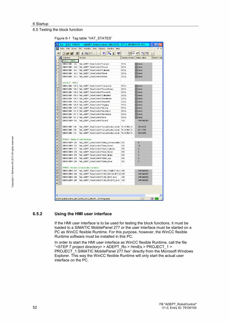
6 Startup 6.5 Testing the block function
52 FB "ADEPT_RobotControl"
V1.0, Entry ID: 79100154
Cop
yrig
ht
Sie
men
s AG
201
3 Al
l rig
hts
rese
rved
Figure 6-1 Tag table “VAT_STATES”
6.5.2 Using the HMI user interface
If the HMI user interface is to be used for testing the block functions, it must be loaded to a SIMATIC MobilePanel 277 or the user interface must be started on a PC as WinCC flexible Runtime. For this purpose, however, the WinCC flexible Runtime software must be installed in this PC. In order to start the HMI user interface as WinCC flexible Runtime, call the file “<STEP 7 project directory> > ADEPT_Ro > HmiEs > PROJECT_1 > PROJECT_1.SIMATIC MobilePanel 277.fwx“ directly from the Microsoft Windows Explorer. This way the WinCC flexible Runtime will only start the actual user interface on the PC.

6 Startup 6.5 Testing the block function
FB "ADEPT_RobotControl" V1.0, Entry ID: 79100154 53
Cop
yrig
ht
Sie
men
s AG
201
3 Al
l rig
hts
rese
rved
Figure 6-2 HMI user interface - “Communication” function
Through the HMI user interface you can now easily control and monitor all inputs and outputs of FB 600 “ADEPT_RobotControl” on the corresponding pages. Figure 6-3 HMI user interface - “Movement” function

7 Operation of the Application 7.1 Starting the communication with the robot controller
54 FB "ADEPT_RobotControl"
V1.0, Entry ID: 79100154
Cop
yrig
ht
Sie
men
s AG
201
3 Al
l rig
hts
rese
rved
7 Operation of the Application The application and thus the entire robot is operated through the function block of the application example. The proceeding for the individual functions of the function block will be described in the following chapters.
7.1 Starting the communication with the robot controller
Enter the connection parameters and the cycle and monitoring times for data exchange via the “ComData” input and then start the connection via the “Connect” input. If the connection to the robot controller was successful, the “Connected” output will be set and the cyclic data exchange between SIMATIC Controller and robot controller will be executed within the specified time frame. After successful connection setup, the robot controller will also issue a message that can be viewed via the “RobotErrorMessage” output. In case an error occurred during connection setup, it can be identified and analyzed via the “Error” and “ErrorID” outputs. Figure 7-1 Communication with the robot controller
FB 600“ADEPT_RobotControl“
ComData
ConnectBOOL
STRUCT
PowerBOOL
CalibrateBOOL
ResetBOOL
BrakeBOOL
JOGSTRUCT
MOVESTRUCT
Connected BOOL
PowerReady BOOL
PowerON BOOL
Calibrated BOOL
ResetDone BOOL
BrakeON BOOL
Jogging BOOL
Moving BOOL
NextMove BOOL
MoveDone BOOL
Error BOOL
ErrorID WORD
ActualPosition STRUCT
RobotErrorMessage STRUCT/STRING
The connection parameters and the cycle and monitoring times for data exchange will be specified via the structure at the “ComData” input. Here, a unique but freely selectable (connection) ID, the IP address of the robot controller and the communication port of the robot controller through which data is exchanged must be defined for each robot. In addition, the cycle time for data exchange between SIMATIC Controller and robot controller must be specified and the monitoring time for the communication connection setup must be defined.

7 Operation of the Application 7.2 Switching on the robot power
FB "ADEPT_RobotControl" V1.0, Entry ID: 79100154 55
Cop
yrig
ht
Sie
men
s AG
201
3 Al
l rig
hts
rese
rved
Figure 7-2 Definition of connection parameters and the cycle / monitoring times
FB 600“ADEPT_RobotControl“
ComData
ConnectINT
Power
Calibrate
Reset
Brake
JOG
MOVE
Connected
PowerReady
PowerON
Calibrated
ResetDone
BrakeON
Jogging
Moving
NextMove
MoveDone
Error
ErrorID
ActualPosition
RobotErrorMessage
DINT
TIME
TIME
ID
IP_Adress
Port
BasicComTime
WatchDogComTime
STRUCT (ARRAY OF BYTE)
Note Any other functions of the robot can only be controlled via the function block if the communication connection with the robot was set up successfully and the connection is currently active.
An active communication connection with the robot controller will be indicated through the “Connected” output of the function block.
DANGER
In case of danger, take additional measures for stopping the robot if the robot movements can no longer be influenced by the SIMATIC Controller.
7.2 Switching on the robot power
If the “Power” input at the function block is set, the command for switching on the robot power will be issued to the robot controller. If the robot controller is ready for switching on the power at the robot, the “PowerReady” output at the function block will be set and the key for switching on the robot power at the robot front panel will be flashing. Pressing the key will switch on the power at the robot and the robot axes will go to controlled mode. This status will be displayed at the function block by setting the “PowerON” output. In case any error occurs at the robot when the power is switched on, this will be indicated via the “Error” and “ErrorID” outputs of the function block. The robot controller can also send out a message concerning the error via the “RobotErrorMessage” output. The potential cause for such an error might be an active emergency stop function at the robot, e.g. if the emergency stop button at the front panel of the robot is pressed.

7 Operation of the Application 7.3 Referencing (calibrating) the robot axes
56 FB "ADEPT_RobotControl"
V1.0, Entry ID: 79100154
Cop
yrig
ht
Sie
men
s AG
201
3 Al
l rig
hts
rese
rved
Figure 7-3 Switching on the robot power
FB 600“ADEPT_RobotControl“
ComData
ConnectBOOL
STRUCT
PowerBOOL
CalibrateBOOL
ResetBOOL
BrakeBOOL
JOGSTRUCT
MOVESTRUCT
Connected BOOL
PowerReady BOOL
PowerON BOOL
Calibrated BOOL
ResetDone BOOL
BrakeON BOOL
Jogging BOOL
Moving BOOL
NextMove BOOL
MoveDone BOOL
Error BOOL
ErrorID WORD
ActualPosition STRUCT
RobotErrorMessage STRUCT/STRING
Figure 7-4 Switching on the robot power at the front panel of the robot
7.3 Referencing (calibrating) the robot axes
Prior to their first use, the robot axes must be calibrated or referenced via the “Calibrate” input. A rising edge at the input will trigger the function. At the “Calibrated” output, the function blocks indicates that the robot axes are referenced or calibrated and can now be used for further movement functions. In case any error occurs at the robot when the power is switched on, this will be indicated via the “Error” and “ErrorID” outputs of the function block. In addition, the robot controller may also output further information on this function via the “RobotErrorMessage” output.
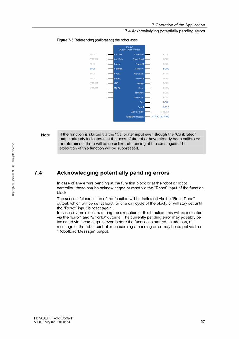
7 Operation of the Application 7.4 Acknowledging potentially pending errors
FB "ADEPT_RobotControl" V1.0, Entry ID: 79100154 57
Cop
yrig
ht
Sie
men
s AG
201
3 Al
l rig
hts
rese
rved
Figure 7-5 Referencing (calibrating) the robot axes
FB 600“ADEPT_RobotControl“
ComData
ConnectBOOL
STRUCT
PowerBOOL
CalibrateBOOL
ResetBOOL
BrakeBOOL
JOGSTRUCT
MOVESTRUCT
Connected BOOL
PowerReady BOOL
PowerON BOOL
Calibrated BOOL
ResetDone BOOL
BrakeON BOOL
Jogging BOOL
Moving BOOL
NextMove BOOL
MoveDone BOOL
Error BOOL
ErrorID WORD
ActualPosition STRUCT
RobotErrorMessage STRUCT/STRING
Note If the function is started via the “Calibrate” input even though the “Calibrated” output already indicates that the axes of the robot have already been calibrated or referenced, there will be no active referencing of the axes again. The execution of this function will be suppressed.
7.4 Acknowledging potentially pending errors
In case of any errors pending at the function block or at the robot or robot controller, these can be acknowledged or reset via the “Reset” input of the function block. The successful execution of the function will be indicated via the “ResetDone” output, which will be set at least for one call cycle of the block, or will stay set until the “Reset” input is reset again. In case any error occurs during the execution of this function, this will be indicated via the “Error” and “ErrorID” outputs. The currently pending error may possibly be indicated via these outputs even before the function is started. In addition, a message of the robot controller concerning a pending error may be output via the “RobotErrorMessage” output.

7 Operation of the Application 7.5 Immediately stopping a robot movement
58 FB "ADEPT_RobotControl"
V1.0, Entry ID: 79100154
Cop
yrig
ht
Sie
men
s AG
201
3 Al
l rig
hts
rese
rved
Figure 7-6 Acknowledging potentially pending errors
FB 600“ADEPT_RobotControl“
ComData
ConnectBOOL
STRUCT
PowerBOOL
CalibrateBOOL
ResetBOOL
BrakeBOOL
JOGSTRUCT
MOVESTRUCT
Connected BOOL
PowerReady BOOL
PowerON BOOL
Calibrated BOOL
ResetDone BOOL
BrakeON BOOL
Jogging BOOL
Moving BOOL
NextMove BOOL
MoveDone BOOL
Error BOOL
ErrorID WORD
ActualPosition STRUCT
RobotErrorMessage STRUCT/STRING
7.5 Immediately stopping a robot movement
If the robot axes are currently moving, this axis movement can immediately be stopped by setting the “Brake” input. The axes cannot be started again as long as the “Brake” input of the function block is set. The “BrakeON” output of the function block indicates that the function for stopping the robot axes is active and that no further travel movement of the axes can be started. In case any error occurs during the execution of this function, this will be indicated via the “Error” and “ErrorID” outputs. In addition, a message of the robot controller concerning this function may be output via the “RobotErrorMessage” output. Figure 7-7 Immediately stopping a robot movement
FB 600“ADEPT_RobotControl“
ComData
ConnectBOOL
STRUCT
PowerBOOL
CalibrateBOOL
ResetBOOL
BrakeBOOL
JOGSTRUCT
MOVESTRUCT
Connected BOOL
PowerReady BOOL
PowerON BOOL
Calibrated BOOL
ResetDone BOOL
BrakeON BOOL
Jogging BOOL
Moving BOOL
NextMove BOOL
MoveDone BOOL
Error BOOL
ErrorID WORD
ActualPosition STRUCT
RobotErrorMessage STRUCT/STRING

7 Operation of the Application 7.6 Moving the robot axes in jog mode
FB "ADEPT_RobotControl" V1.0, Entry ID: 79100154 59
Cop
yrig
ht
Sie
men
s AG
201
3 Al
l rig
hts
rese
rved
7.6 Moving the robot axes in jog mode
The robot axes can be moved in the different coordinate systems of the robot in jog mode via the “JOG” input. Active travel movement of the robot axes in jog mode will be indicated via the “Jogging” output. In case any error occurs during the execution of this function, this will be indicated via the “Error” and “ErrorID” outputs. In addition, a message of the robot controller concerning this function may be output via the “RobotErrorMessage” output. Figure 7-8 Moving the robot axes in jog mode
FB 600“ADEPT_RobotControl“
ComData
ConnectBOOL
STRUCT
PowerBOOL
CalibrateBOOL
ResetBOOL
BrakeBOOL
JOGSTRUCT
MOVESTRUCT
Connected BOOL
PowerReady BOOL
PowerON BOOL
Calibrated BOOL
ResetDone BOOL
BrakeON BOOL
Jogging BOOL
Moving BOOL
NextMove BOOL
MoveDone BOOL
Error BOOL
ErrorID WORD
ActualPosition STRUCT
RobotErrorMessage STRUCT/STRING
Jog mode is controlled through the structure of the “JOG” input. “JOG_Mode” enables switching between the Cartesian coordinate system (“jog_world_mode” input), the tool coordinate system (“jog_tool_mode” input), and the axis coordinate system (“jog_joint_mode” input). The dynamic parameters for the jog mode of the axes, such as speed (“speed” input), acceleration (“acceleration” input), and deceleration (“deceleration” input) and the dynamic profile (“acceleration_profile” input) will be specified via the “JOG_MotionParameters”. After that, through the “JOG_Buttons”, the respective axis can be moved, and several axes can be selected at the same time. The robot axes will keep moving as long as the corresponding jog buttons are pressed.

7 Operation of the Application 7.7 Executing coordinated movements
60 FB "ADEPT_RobotControl"
V1.0, Entry ID: 79100154
Cop
yrig
ht
Sie
men
s AG
201
3 Al
l rig
hts
rese
rved
Figure 7-9 Controlling the jog mode
FB 600“ADEPT_RobotControl“
ComData
ConnectBOOL
Power
Calibrate
Reset
Brake
JOG
MOVE
Connected
PowerReady
PowerON
Calibrated
ResetDone
BrakeON
Jogging
Moving
NextMove
MoveDone
Error
ErrorID
ActualPosition
RobotErrorMessage
JOG_MotionParameters
JOG_Buttons
JOG_Mode
jog_joint_mode
jog_tool_mode
jog_world_mode
Jog_joint_1_or_x_plus
Jog_joint_1_or_x_minus
Jog_joint_6_or_rol_plus
Jog_joint_6_or_rol_minus
...
speed
acceleration
deceleration
acceleration_profile
BOOL
BOOL
BOOL
BOOL
BOOL
BOOL
INT
INT
INT
INT
7.7 Executing coordinated movements
One or more coordinated and chained movements of the robot can be executed, with a target position specified, via the “MOVE” input. Active travel movement of the robot axes will be indicated via the “Moving” output. The “NextMove” output indicates that a further moving command for a chained sequence of movements can be transferred to the function block, allowing orbital movements of the robot with several support points to be executed. The “MoveDone” ouput indicates that a single movement or a chained sequence of movements or orbital movement was fully executed and completed. This output will be displayed at least for one call cycle of the block, or until the “MOVE.command.Execute” input is reset. In case any error occurs during the execution of this function, this will be indicated via the “Error” and “ErrorID” outputs. In addition, a message of the robot controller concerning this function may be output via the “RobotErrorMessage” output.

7 Operation of the Application 7.7 Executing coordinated movements
FB "ADEPT_RobotControl" V1.0, Entry ID: 79100154 61
Cop
yrig
ht
Sie
men
s AG
201
3 Al
l rig
hts
rese
rved
Figure 7-10 Executing coordinated movements
FB 600“ADEPT_RobotControl“
ComData
ConnectBOOL
STRUCT
PowerBOOL
CalibrateBOOL
ResetBOOL
BrakeBOOL
JOGSTRUCT
MOVESTRUCT
Connected BOOL
PowerReady BOOL
PowerON BOOL
Calibrated BOOL
ResetDone BOOL
BrakeON BOOL
Jogging BOOL
Moving BOOL
NextMove BOOL
MoveDone BOOL
Error BOOL
ErrorID WORD
ActualPosition STRUCT
RobotErrorMessage STRUCT/STRING
The moving functions of the robot will be controlled through the structure of the “MOVE” input. The properties of the required movement are defined by means of the qualifiers. They allow the setting whether the target specification of the movement is an absolute or a relative position specification (“relative_mode” input), whether the position is specified in the Cartesian coordinate system or in the axis coordinate system (“joint_coordinates” input), whether the movement is to be executed on a straight line (“straightline_move” input), whether the command shall be chained to the next command (“nonull” input), and whether the specified target position is to be targeted precisely or only approximately (“coarse_nulling” input). The movement of the rotary axes can also be limited (“single_turn” input) or the arm positions of the robot can be defined (“righty_configuration”, “below_configuration”, and “flip_configuration” inputs). The dynamic properties of the movement or the sequence of movements will be defined through the “parameters” structure. Finally the target position of the movement or the individual support point of a sequence of movements will be defined through the “location_data” structure. This structure also has the two sub-structures “world” and “joint” which, for security reasons, will be selected in dependence of the “qualifiers.joint_coordinates” input: • If the “qualifiers.joint_coordinates” input is set, the target position will be taken
from the “joint” structure. The movement will then be executed in the axis coordinate system.
• If the “qualifiers.joint_coordinates” input is not set, the target position will be taken from the “world” structure. The movement will then be executed in the Cartesian coordinate system.
The sub-structures each have six parameter inputs for the target position in the Cartesian coordinate system of the “world“ structure (inputs “X“, “Y“, “Z“, “Yaw“, “Pitch“, “Roll“) or in the axis coordinate system of the “joint“ structure (inputs “joint_1“, “joint_2“, “joint_3“, “joint_4“, “joint_5“, “joint_6“). Finally the parameterized movement can be started via the “command.Execute” input.

7 Operation of the Application 7.7 Executing coordinated movements
62 FB "ADEPT_RobotControl"
V1.0, Entry ID: 79100154
Cop
yrig
ht
Sie
men
s AG
201
3 Al
l rig
hts
rese
rved
Figure 7-11 Controlling the “MOVE” function
FB 600“ADEPT_RobotControl“
ComData
Connect
BOOL
Power
Calibrate
Reset
Brake
JOG
MOVE
Connected
PowerReady
PowerON
Calibrated
ResetDone
BrakeON
Jogging
Moving
NextMove
MoveDone
Error
ErrorID
ActualPosition
RobotErrorMessage
parameters
qualifiers
commandexecute
relative_move
joint_coordinates
single_turn
righty_configuration
speed
acceleration
deceleration
acceleration_profile
BOOL
BOOL
BOOL
BOOL
INT
INT
INT
INT
location_data
straightline_move
nonull
coarse_nulling
below_configuration
flip_configuration
BOOL
BOOL
BOOL
BOOL
BOOL
world
joint
STRUCT
STRUCT
7.7.1 Executing a single movement
The properties of the movement will be defined through the structures “qualifiers” and “parameters” and the target position will be set through the “location_data” structure. After that, a rising edge at the “MOVE.command.Execute” input will start the movement. The active movement will be indicated via the “Moving” output. Once the “NextMove” output is set, the command for another movement for a sequence of movements could be given. However, this output is of no significance for executing a single movement. After successful execution of the movement the “Moving” output will be reset and the “MoveDone” output will be set, which will stay active until the “MOVE.command.Execute” input is reset again. Figure 7-12 Executing a single movement
Moving
MOVE.command.Execute
NextMove
MoveDone
t
7.7.2 Executing a sequence of movements
If a sequence of movements is to be executed, the properties of the movement must first be defined through the structures “qualifiers” and “parameters” and the target position of the first movement, i.e. the first support point of the movement, will be set through the “location_data” structure.

7 Operation of the Application 7.7 Executing coordinated movements
FB "ADEPT_RobotControl" V1.0, Entry ID: 79100154 63
Cop
yrig
ht
Sie
men
s AG
201
3 Al
l rig
hts
rese
rved
Then a rising edge at the “MOVE. command.Execute“ input will start the sequence of movements. The active movement will be indicated via the “Moving” output. Once the “NextMove” output is set, the properties of the movement can be defined through the structures “qualifiers” and “parameters” and the target position of the next movement, i.e. the next support point of the movement, will be set through the “location_data” structure. Then a rising edge at the “MOVE. command.Execute“ input will activate the next movement. This movement will be executed as soon as the previous movement has been completed with the defined properties. Once the “NextMove” output is set again, the command for the next movement can be given. This process will repeat until the command for the last movement of the sequence of movements has been given. After successful execution of the sequence of movements, or the last movement of the sequence, the “Moving” output will be reset and the “MoveDone” output will be set, which will stay active until the “MOVE.command.Execute” input is reset again. Figure 7-13 Executing a sequence of movements
Moving
MOVE.command.Execute
NextMove
MoveDone
t
1 2 3Movement
Note If the individual movements in a sequence of movements are to be “blended”, i.e. executed without stopping the robot axis between the individual movements, the command for the follow-up movement must be given while the current movement is still being executed.
In addition, the “MOVE.Qualifiers.nonull” input must be set for each movement of the sequence.

8 Related Literature
64 FB "ADEPT_RobotControl"
V1.0, Entry ID: 79100154
Cop
yrig
ht
Sie
men
s AG
201
3 Al
l rig
hts
rese
rved
8 Related Literature 8.1 Bibliography
This list is by no means complete and only represents a selection of relevant literature. Table 8-1
Subject Title
/1/ STEP7 SIMATIC S7-300/400
Automating with STEP7 in STL and SCL Author: Hans Berger Publicis MCD Verlag ISBN: 978-3895784125
/2/ STEP7 SIMATIC S7-300/400
Automating with STEP7 in LAD and FBD Author: Hans Berger Publicis MCD Verlag ISBN: 978-3895784101
/3/ STEP7 SIMATIC S7-300
Automating with SIMATIC S7-300 inside TIA Portal Author: Hans Berger Publicis MCD Verlag ISBN: 978-3895783821
8.2 Internet Links
The following list is not complete and only represents a selection of relevant information. Table 8-2
Subject Title
\1\ Reference to this entry
http://support.automation.siemens.com/WW/view/en/79100154
\2\ Siemens Industry Online Support
http://support.automation.siemens.com
9 History Table 9-1
Version Date Modifications
V1.0 08/2013 First version