adeq draft operating air permit€¦ · ... permit history ... air defense missile system •...
TRANSCRIPT

ADEQ DRAFT
OPERATING AIR PERMIT
Pursuant to the Regulations of the Arkansas Operating Air Permit Program, Regulation 26:
Permit No. : 0617-AOP-R16
IS ISSUED TO:
Aerojet Rocketdyne, Inc. East Walton Road, (Highway 274), Highland Industrial Park
East Camden, AR 71701 Calhoun County AFIN: 07-00035
THIS PERMIT AUTHORIZES THE ABOVE REFERENCED PERMITTEE TO INSTALL, OPERATE, AND MAINTAIN THE EQUIPMENT AND EMISSION UNITS DESCRIBED IN THE PERMIT APPLICATION AND ON THE FOLLOWING PAGES. THIS PERMIT IS VALID BETWEEN:
April 8, 2015 AND April 7, 2020 THE PERMITTEE IS SUBJECT TO ALL LIMITS AND CONDITIONS CONTAINED HEREIN. Signed: Stuart Spencer Date Associate Director, Office of Air Quality

Aerojet Rocketdyne, Inc. Permit #: 0617-AOP-R16 AFIN: 07-00035
2
Table of Contents SECTION I: FACILITY INFORMATION .............................................................................. 5 SECTION II: INTRODUCTION ............................................................................................... 6
Summary of Permit Activity .................................................................................................... 6 Process Description ................................................................................................................... 6 Regulations .............................................................................................................................. 13 Emission Summary ................................................................................................................. 14
SECTION III: PERMIT HISTORY ........................................................................................ 37 SN-02A, 02B, 02C, 02D, 02E, 02F, 02G, 25A, 25C, 25E, 25F, 69C, 69D, 69E, 69F, 69G, 69H, SN-94, SN-96, SN-97, 101A and 101B .......................................................................... 42 Natural Gas-Fired Boilers and Heaters ................................................................................ 42 SN-03A, 03B, 03C, 03D, 03E, 03F, 03G - Rocket Test Facility ........................................... 48 SN-04 - Thermal Treatment Facility ..................................................................................... 51 SN-07 - Liner Mixer and Spray Liner Machine ................................................................... 53 SN-11 - Lacquer Preparation ................................................................................................. 54 SN-12 - Spray Paint Booth ..................................................................................................... 55 SN-13 - Ultrasonic Cleaner .................................................................................................... 56 SN-19 - Motor Case Cleaner .................................................................................................. 57 SN-20A and B - Solvent Wipe Rooms ................................................................................... 58 SN-22 - Mix Room ................................................................................................................... 59 SN-24 - Spray Paint Booth ..................................................................................................... 60 SN-28 - Spray Liner Machine and Mixer Unit ..................................................................... 61 SN-30 - High Explosives Test Facility ................................................................................... 62 SN-36 - Vapor Degreaser........................................................................................................ 64 SN-37A and B - Motor Case Cleaning (Prior to Grit Blasting) .......................................... 65 SN-38A and B - Motor Case Cleaning (After Grit Blasting) .............................................. 66 SN-39A and B - Adhesive Primer Operations ...................................................................... 67 SN-40A and B - Adhesive Operations ................................................................................... 69 SN-41A and 41B - Adhesive Barrier Coating Operations ................................................... 71 SN-42 - Spray Liner Machine ................................................................................................ 73 SN-43 - Spray Paint Booth ..................................................................................................... 74 SN-44A, 44B, 44C, 44D - Floor Operations .......................................................................... 75 SN-47 - Foam-Blowing Operations........................................................................................ 79 SN-48A and B - Phenolic Molding Operations..................................................................... 80 SN-49 - Hockey Puck Manufacturing ................................................................................... 82 SN-52A and B - Sling Liner Machines .................................................................................. 83 SN-56 - MK 104 Sample Collection ....................................................................................... 84 SN-63 - Nitramines and Explosives Dryer ............................................................................ 85 SN-67A through R - Grit Blast Machines ............................................................................. 86 SN-71 - Gasoline Storage Tank .............................................................................................. 89 SN-72 - Diesel Fuel Storage Tanks ........................................................................................ 90 SN-73 - Nitramines and Explosives Grinder ........................................................................ 91 SN-74 - Solvent Wipe Room Building M-2 ........................................................................... 92 SN-75 - Sling Liner Machine Building M-2 .......................................................................... 93
Aerojet Rocketdyne, Inc. Permit #: 0617-AOP-R16 AFIN: 07-00035
3
SN-76A and 76B - Adhesive Primer Operations .................................................................. 94 SN-77A and 77B - Adhesive Operations ............................................................................... 96 SN-78A and 78B - Adhesive Barrier Coating Operations ................................................... 98 SN-80 - Warhead Coating Operation .................................................................................. 100 SN-81 - Diesel-Powered Pump at Rocket Motor Case Washout Facility ........................ 101 SN-84 - Warhead Manufacturing Operations .................................................................... 104 SN-85 - Motor Case Cleaning Operations .......................................................................... 106 SN-86, SN-87, SN-89, SN-90, SN-91, SN-92, SN-93, SN-95, SN-102, SN-103, SN104, and SN-105 Emergency Power Generators ................................................................................ 107 SN-98 – Spray Liner Operation at Building M-125 ........................................................... 113 SN-99 - Spray Liner Machine (Building 102) ..................................................................... 115 SN-100A and 100B - Floor Operations at Building 101 and Building 102 ...................... 116 SN-104 - Propellant Cutting Operation (Building C39) .................................................... 118
SECTION V: COMPLIANCE PLAN AND SCHEDULE ................................................... 120 SECTION VI: PLANTWIDE CONDITIONS ...................................................................... 121
40 C.F.R 63 Subpart GG (Aerospace) Requirements ........................................................ 126 SECTION VII: INSIGNIFICANT ACTIVITIES................................................................. 130 SECTION VIII: GENERAL PROVISIONS ......................................................................... 131 Appendix A Appendix B Appendix C

Aerojet Rocketdyne, Inc. Permit #: 0617-AOP-R16 AFIN: 07-00035
4
List of Acronyms and Abbreviations
Ark. Code Ann. Arkansas Code Annotated
AFIN ADEQ Facility Identification Number
C.F.R. Code of Federal Regulations
CO Carbon Monoxide
HAP Hazardous Air Pollutant
lb/hr Pound Per Hour
MVAC Motor Vehicle Air Conditioner
No. Number
NOx Nitrogen Oxide
PM Particulate Matter
PM10 Particulate Matter Smaller Than Ten Microns
SNAP Significant New Alternatives Program (SNAP)
SO2 Sulfur Dioxide
SSM Startup, Shutdown, and Malfunction Plan
Tpy Tons Per Year
UTM Universal Transverse Mercator
VOC Volatile Organic Compound

Aerojet Rocketdyne, Inc. Permit #: 0617-AOP-R16 AFIN: 07-00035
5
SECTION I: FACILITY INFORMATION
PERMITTEE: Aerojet Rocketdyne, Inc.
AFIN: 07-00035
PERMIT NUMBER: 0617-AOP-R16
FACILITY ADDRESS: East Walton Road, (Highway 274), Highland Industrial Park East Camden, AR 71701
MAILING ADDRESS: Post Office Box 1036 Camden, AR 71711-1036
COUNTY: Calhoun County
CONTACT NAME: J'Ne Chilcote
CONTACT POSITION: SH&E Manager TELEPHONE NUMBER: (870) 574-3440
REVIEWING ENGINEER: Shawn Hutchings
UTM North South (Y): Zone 15: 3721136.22 m UTM East West (X): Zone 15: 528500.00 m

Aerojet Rocketdyne, Inc. Permit #: 0617-AOP-R16 AFIN: 07-00035
6
SECTION II: INTRODUCTION
Summary of Permit Activity Aerojet Rocketdyne, Inc. currently operates a manufacturing facility located in the Highland Industrial Park near East Camden, Arkansas. This permit includes a minor modification to install two emergency generators, SN-105 and 106, and two administrative amendments to add a grit blaster (category A-13) and three water heaters (category A-1) to the insignificant activities list. Sources SN-25B and 25D were removed. Permitted emissions increased. 0.4 tpy of particulate, 0.4 tpy of SO2, 0.5 tpy of VOC, 1 tpy of CO, and 8.4 tpy of NOx.
Process Description DESCRIPTION OF GENERIC ROCKET MOTOR PRODUCTION PROGRAM Aerojet Rocketdyne manufactures a number of solid rocket motors for the U.S. Department of Defense (DoD) and other military contractors. These production programs include the following:
• MK-104 Ballistic Missile Defense System • Army Tactical Missile System (ATACMS) • Multiple Launch Rocket System (MLRS) • Patriot (PAC-2) Air Defense Missile System • Patriot (PAC-3) Air Defense Missile System • Tactical Tomahawk Cruise Missile System • Sidewinder Air-To-Air Missile System • Javelin Air Defense Missile System • Stinger Portable Air Defense System • Supersonic Sea-Skimming Target (SSST) Missile System • TOW Missile System • Terminal High Altitude Aerial Defense (THAAD)
A generic description of the manufacturing operations for a typical rocket motor program is provided below. Motor Case Preparation Production of a typical rocket motor commences with the receipt of pre-manufactured metal motor cases from a vendor. Each case is subsequently cleaned to remove residual oil and grease. Cleaning is performed using one of two degreaser units: the motor case cleaner (vapor degreaser) at Building 2-SH-14 (SN-19) or the aqueous degreaser at Building 2-SH-2 (no SN). As an alternative, the motor case may be manually cleaned. The hand-wipe cleaning activities (SN-37) are conducted at Buildings 2-SH-2 and 2-SH-14.

Aerojet Rocketdyne, Inc. Permit #: 0617-AOP-R16 AFIN: 07-00035
7
After cleaning, the rocket motor case is grit blasted at Building 2-SH-2 or 2-SH-14. This operation prepares the interior surface of the metal case for coating. Sand, coal slag, steel grit, and other materials are used as the abrasive media. The particulate emissions from the grit blast machines (SN-67) are controlled using various devices (cyclones, baghouses, shop vacuums, etc.). After grit blasting, the case is degreased a second time. Cleaning is again performed using the motor case cleaner (SN-19) at Building 2-SH-14 or the aqueous degreaser at Building 2-SH-2. As an alternative, the case may be hand-wipe cleaned (SN-38) at either location. Once clean, the rocket motor case is transported to Building M-2. At this time, the case is physically inspected for defects using a "Magnaflux" machine. This equipment is a specially-designed black-light fluoroscope (SN-68). It is used to examine metal components for hairline cracks and other flaws. After inspection, the rocket motor case is transferred to Building 2-SH-14, 2-SH-15, or M-8 (or remains at M-2) for adhesive application. First, an adhesive primer is applied to the interior surface of the case (SN-39 and SN-76). The coating is applied within enclosed production bays. Depending on the program, the adhesive primer is manually applied using paintbrushes (SN-39) at Buildings 2-SH-14 and 2-SH-15. The facility also operates adhesive spray machines at Buildings M-2 and M-8. Each automated unit consists of a spray nozzle mounted on a traveling wand. During application of the adhesive primer (SN -76), the wand is slowly drawn through the motor case to provide a uniform coating. Afterwards, the case is either allowed to air dry at ambient temperature or is cured in a steam-heated oven (no SN). Next, the motor case is coated with an adhesive. Depending on the production program, the coating is manually applied (SN-40) at Buildings 2-SH-14 and 2-SH-15 or is applied using the spray machines (SN-77) at Buildings M-2 and M-8. The motor case is then allowed to air dry or is cured in an oven. Rubber insulators are fabricated concurrent with preparation of a typical rocket motor case. This production operation is conducted at Buildings 2-SH-14 and M-2. The "case rubber" for the rocket motor is made by "laying up" (wrapping) rubber sheeting around a metal forming tool (a mandrel). The unit is then cured in an oven. The finished rubber piece has a cylindrical shape. After fabrication, the insulator component is degreased with a solvent. The hand-wipe cleaning operations are performed within enclosed rooms at Building 2-SH-14 (SN-20), Building 2-SH-15 (SN-20), or Building M-2 (SN-74). After cleaning, the case rubber is installed within the prepared motor case. Tooling is then attached to the case assembly ("tool-up" process). The motor case is subsequently subjected to a series of mechanical and physical tests for quality control purposes. After testing, the entire insulated case assembly is cured within an oven. The tooling is then removed from the motor case ("de-tooling" process). The insulated motor case is subsequently wiped down with a solvent (SN-20 and SN-74).

Aerojet Rocketdyne, Inc. Permit #: 0617-AOP-R16 AFIN: 07-00035
8
After degreasing, the rocket motor case is returned to the oven for an extended period of curing (several days). Next, the case is again hand-wipe cleaned (SN-20 and SN-74). An adhesive barrier coating is subsequently applied to the interior surface of the insulated motor case. The coating is manually applied using paintbrushes (SN-41) at Buildings 2-SH-l4 and 2-SH-l5, or is applied using the spray machines (SN-78) at Buildings M-2 and M-8. The case is then cured again in an oven (IE). The prepared rocket motor case is subsequently lined with a polyurethane coating. Lining of Prepared Motor Case Once prepared, the interior of the typical rocket motor case is lined with a specially formulated polyurethane coating. The liner compounds are prepared for use in the mixer units at Building M-8 (SN-07), Building 2-SH-l5 (SN-22), Building M-125 (SN-98), and Building M-2 (SN-28). (The liner mixtures are composed of a polymer, curing agent, bonding agent, and a filler. These materials are not volatile. The coatings are prepared within closed mixer units. As a result, the mixing operations themselves are insignificant sources of air emissions. However, various solvents are used to clean the liner mixers.) The prepared liner material is first applied by hand to the dome areas of the rocket motor case. The case is then cured in an oven. The remaining interior sections of the cylindrical case are then coated with the liner material. Application is performed using several "sling liner" machines. Each automated unit consists of a rotating applicator head mounted on a traveling wand. During liner application, the wand is slowly drawn through the motor case to provide a uniform coating. The spinning head slings the liner onto the inside of the case. The lined rocket motor case is then cured in an oven. The facility operates sling liner machines at Building 2-SH-15 (SN-52), Building M-8 (SN-52), and Building M-2 (SN-75). Depending on the production program, the liner material may also be applied using a "spray liner machine." Each automated unit consists of a spray nozzle mounted on a traveling wand. During application of the liner, the wand is slowly drawn through the motor case to provide a uniform coating. The lined rocket motor case is then cured in an oven. The facility operates spray liner machines at Building M-8 (SN-07), Building M-2 (SN-28), and Building 2-SH-15 (SN-42). A specialized spray liner operation, SN-98, is also performed at Building M-125. The lined rocket motor case is now ready for loading with solid propellant ("casting" process). Fabrication of Nozzle Assembly The "nozzle assembly" for the typical rocket motor is fabricated in a separate series of operations. This component is made of a composite carbon/phenolic resin material plus pre-manufactured metal and plastic hardware. First, sections of carbon-impregnated phenolic resin tape are die cut to the desired sizes and shapes. The cut patterns are then assembled and press molded to form a rigid plastic nozzle. The press machines at Buildings 2-SH-3 or 2-SH-14 (both

Aerojet Rocketdyne, Inc. Permit #: 0617-AOP-R16 AFIN: 07-00035
9
SN-48) are utilized. After molding, the nozzle unit is machined to attain the proper dimensions. The metalworking lathes (IE) at Building 2-SH-3 (SN-66) are used for this operation. The nozzle unit is then assembled at Building 2-SH-14 or Building M-2 (or elsewhere). The metal and plastic components are manually glued together using small quantities of epoxy and/or urethane adhesives. The nozzle unit is subsequently wiped down with a solvent. The hand-wipe cleaning operations are performed at Building 2-SH-14 (SN-20) or Building M-2 (SN-74). The entire nozzle assembly is then transported to Building 33 or Building 48 for installation on the motor case. Fabrication of Igniter Assembly Launch of a typical rocket motor is initiated using an electrically-fired igniter. Fabrication of the igniter assembly is performed as follows: First, the pre-manufactured metal igniter cup is etched with acid. This bench-top operation is conducted in the Chemistry Lab at Building B-17. Concurrently, the pre-manufactured plastic igniter components are cut to size, hand-wiped with solvent and glued together. The plastic parts are then combined with the etched metal cup to form the igniter assembly. These production operations are performed at Building M-85. The fugitive air emissions from the small-scale cleaning and gluing activities are accounted for in the facility-wide "floor operations" (SN-44). After assembly, a small charge of propellant is placed within the igniter. The loaded component is then sealed. The finished igniter unit is subsequently shipped to Building 33 or Building 48 for installation within the motor case. Casting, Curing and Assembly of Finished Rocket Motor As stated above, the interior of the clean rocket motor case is coated with a primer and an adhesive. A "case rubber" insulator is then installed within the unit. Following an extended oven-curing period, an adhesive barrier coating is applied to the rubber insulator. The interior of the case is then lined with a polyurethane material. After curing, the lined motor case is ready for propellant "casting." An integral component of the facility’s manufacturing activities is the formulation of solid rocket propellants that perform to exacting specifications. In general, propellant production involves the combining of various dry energetic materials (premix, oxidizer, and fuel), plus liquid polymers and plasticizers/curing agents, within a mechanical mixer. The ingredients are then consolidated into a uniform propellant formulation. Mixer units are operated at multiple locations throughout the East Camden complex. (All of the dry and liquid ingredients are handled in a controlled manner. The liquid polymers and curing agents are not volatile. No significant air emissions are generated during the mixing operations.) Once formulated, the rocket fuel is "cast" (loaded) within the prepared rocket motor case. During this operation, the lined case is filled with the propellant/polymer/plasticizer mixture

Aerojet Rocketdyne, Inc. Permit #: 0617-AOP-R16 AFIN: 07-00035
10
while under vacuum. The fuel mixture is then allowed to cure within the motor case. (The casting and curing activities are insignificant sources of air emissions.) A number of propellant casting and curing stations are operated throughout the facility. Upon receipt at a particular building, the case is "tooled-up" and positioned at the casting station. Preparation of the case may include insertion of a metal mandrel. Use of the forming tool creates a hollow core within the cast propellant. The motor case is then filled with the fuel mixture. After casting, the case is loaded into a steam-heated or electric oven. The propellant is then cured under controlled temperature conditions. Once cured, the motor case is removed from the oven and allowed to cool. The mandrel is then withdrawn from the cast motor case ("core pull" operation). Next, any propellant residue on the exterior of the case is manually removed for later disposal ("cut back" operation). Finally, the tooling is removed from the motor case. At this time, the cast and cured rocket motor case is transported to Building 33 or Building 48 for final assembly. First, a primer coat of paint is applied to the exterior of the motor case. The unit is then allowed to air dry. As an alternative, the case may be cured in a steam-heated oven. The facility operates spray paint booths at Building 33 (SN-43) and Building 48 (SN-24). The coatings are applied using air-assisted paint guns. The paint booths are equipped with high-density mesh filters for the control of over-spray. Small-scale painting activities are also conducted at Building 60 (SN-12) and Building M-85 (SN-83). Afterwards, a topcoat of paint is applied to the rocket motor case within one of the spray booths (SN-24 or SN-43). The unit is then allowed to air dry or is cured in an oven. The nozzle assembly and igniter are now installed on the motor case. The entire unit is then leak tested for quality control purposes. An inert gas (nitrogen, helium, or argon) is utilized. After leak testing, the rocket motor case is transported to Building 46. The motor is then x-rayed to check for defects. Other quality control testing is also performed at this time. The finished rocket motor is then labeled and packaged. These operations are performed at Building 33 or Building 48. The fugitive air emissions from the labeling activities are part of the floor operations (SN-44). The rocket motors are then stored pending shipment off-site. Other DoD contractors perform the final assembly of most of the rocket motors made. PROPELLANT TESTING AND TREATMENT UNITS Aerojet Rocketdyne tests rocket and air bag propellant formulations at the East Camden facility. Waste energetic materials are treated on-site. These operations are discussed below:

Aerojet Rocketdyne, Inc. Permit #: 0617-AOP-R16 AFIN: 07-00035
11
Rocket Test Facility (RTF) Rocket motors, air bag initiators, and other energetic devices are test fired for quality control and R&D purposes. These activities are performed at multiple locations throughout the East Camden complex. The rocket test sites include Bays 15, 18, 45, and 49; and Buildings 16, M-85, and M-125. The RTF (SN-03) encompasses all of these locations. To prepare for a test event, the rocket motor assembly is fitted with instrumentation and then temperature-conditioned. Once conditioning is complete, the motor is secured to a specially designed test stand. The rocket is then fired from a remote control building. Various test data are recorded during the event. After a cool-down period, the spent motor case is disassembled and evaluated. The test bays and apparatus are not equipped with air pollution control devices. Air bag igniters, inflators, and other small energetic devices are also test fired for production and R&D purposes. A particular component is assembled, temperature-conditioned, secured to special test equipment, and then fired. Various test data are recorded during the event. The hardware is then disassembled and evaluated. The testing units are not equipped with air pollution control devices. Thermal Treatment Facility (TTF) Waste rocket and air bag propellants and propellant-contaminated materials are generated during the facility's manufacturing operations. These waste streams are destroyed via open burning in the TTF. It is a permitted hazardous waste treatment unit. To prepare for a thermal treatment event, the waste materials are transported from temporary storage areas to the TTF. The wastes are then placed in the burn pans, burn cages, rocket firing fixture, and/or miscellaneous treatment devices. Once preparations are complete, the materials are ignited using an electric current. Ignition is initiated from the remote control building. The wastes are then allowed to burn until combustion has been completed. After the event, the treatment devices are allowed to cool for 24 hours. The items are then prepared for reuse. The treatment units are not equipped with air pollution control devices. High Explosives Test Facility (EXTEF) This site is used to support the manufacturing operations at the East Camden complex. Ordnance, explosives, and other energetic materials are tested at the EXTEF (SN-30) for quality control and R&D purposes. The items that are test-fired range from finished automobile air bag systems to various military ordnance to specially-prepared experimental propellant formulations. The tests are conducted under a variety of physical conditions. Denotation or ignition of a particular component may be initiated by dropping the item onto a hard surface, by the impact of a bullet, by a blasting cap-initiated high-explosive donor charge, or by a controlled bonfire. The test events are initiated and monitored from a control building. Various test data are recorded during each detonation event for subsequent evaluation. The test-firing area and apparatus are not equipped with air pollution control devices.

Aerojet Rocketdyne, Inc. Permit #: 0617-AOP-R16 AFIN: 07-00035
12
The EXTEF is located within the 16-A T Area of the Highland Industrial Park. It is situated approximately ten miles away from the main manufacturing complex. MISCELLANEOUS MANUFACTURING OPERATIONS AND EQUIPMENT Aerojet Rocketdyne operates several miscellaneous production units at the East Camden facility. The most significant of these items are discussed below: Lacquer Preparation Operations "Lacquer" is the facility's generic term for various liquid explosive compounds. These products are processed at Building 56. There are two general categories of operations involving lacquer: (1) the preparation of premixed lacquer solutions for use in propellant production and (2) the stabilization of lacquer premix for shipping and/or long-term storage. When purchased from vendors, the lacquer products are premixed with a solvent, usually methylene chloride or isopropyl alcohol. The solvent acts as a stabilizing agent during transportation. To prepare the lacquer for subsequent use, the solvent is removed by sparging with nitrogen gas. The lacquer is then transferred to the mixing area for processing. All stripping of lacquer premix (SN-11) is performed at Building 56. The sparging operation is a batch process. The second category of lacquer preparation involves the addition of stabilizing materials to liquid explosives prior to their use, shipment, and/or long-term storage. The stabilization process (SN-11) is also performed at Building 56. The solvents and explosives are combined in a mixing vessel. The resultant lacquer premix is then packaged for use, transportation or storage. Explosives Dryer The facility uses various energetic materials ("nitramine" compounds) and explosives in its production operations. When purchased from vendors, these products are wetted with isopropyl alcohol. The solvent acts as a stabilizing agent for safety purposes. Prior to use, the energetic materials are processed in a rotary vacuum dryer (SN-63). This unit is located at Building 57. The dryer operates as follows: The explosive compounds are received in plastic bags. The containers are manually opened, and the materials are placed in the rotary drum dryer. The building is secured once the unit is loaded. The dryer is then heated using a hot-water jacket, while a vacuum pump simultaneously exhausts the dryer chamber. During operation, the chamber is periodically rotated to ensure thorough drying of its contents. Once dry, the energetic materials are ready for further processing. The vacuum pump is equipped with a chiller system, which condenses the solvent in the off-gas stream. Explosives Grinder

Aerojet Rocketdyne, Inc. Permit #: 0617-AOP-R16 AFIN: 07-00035
13
After drying, the nitramine compounds and explosives are milled to the proper particle size. A specialized grinder unit (SN-73) is operated at Building 58 for this purpose. Once prepared, the ground energetic materials are used in the production of rocket propellants and related compounds. The nitramines and explosives grinder is equipped with two baghouses for the control of dust emissions. Rocket Motor Case Reclamation Facility Certain rocket motors cannot be fired due to damage or the age of the units. The propellants are removed from these products so that the metal motor cases can be reclaimed. First, the bulk propellant is mechanically removed using an electric-powered lathe ("hogout" operation). The remaining propellant is then extracted using a high-pressure spray of water ("washout operation"). A 300 horsepower diesel-fired internal combustion engine (SN-81) is used to power the water pump for the "hydro-lance machine." Warhead Manufacturing Operations The facility makes a variety of warheads and other ordnance (SN-84) at Building M-11. The production activities include two coating operations. An asphalt or wax compound is applied to the inside of certain warhead units. The "stress-relaxing liner" prevents the explosive charge inside the case from cracking as the material cools after installation. Two "melter/applicator machines" are operated for this purpose. The hot liner material is applied to the warhead cases using a hand-held wand. The asphalt or wax coating hardens as the components cool. The lined warhead cases are subsequently filled with an explosive. SOURCES OF AIR EMISSIONS The two largest individual sources of air emissions at the East Camden plant are utilized for the testing and disposal of rocket propellants and other energetic materials. These units are the Rocket Test Facility (SN-03) and the Thermal Treatment Facility (SN-04/04R). The facility's manufacturing operations and associated plant activities also represent a number of air emission sources at the East Camden facility. These operations include the following: multiple parts cleaning activities involving solvents; a variety of surface coating operations; parts assembly using specialty adhesives; the production of rocket and air bag propellants, explosives, and other energetic materials; the operation of natural gas-fired combustion equipment; R&D activities; and a number of miscellaneous production operations.
Regulations The following table contains the regulations applicable to this permit.
Regulations

Aerojet Rocketdyne, Inc. Permit #: 0617-AOP-R16 AFIN: 07-00035
14
Arkansas Air Pollution Control Code, Regulation 18, effective March 14, 2016 Regulations of the Arkansas Plan of Implementation for Air Pollution Control, Regulation 19, effective March 14, 2016 Regulations of the Arkansas Operating Air Permit Program, Regulation 26, effective March 14, 2016 40 C.F.R 63 Subpart GG - National Emission Standards for Aerospace Manufacturing and Rework Facilities 40 C.F.R 63 Subpart ZZZZ - National Emission Standards for Hazardous Air Pollutants for Reciprocating Internal Combustion Engines 40 C.F.R Part 60 Subpart JJJJ - Standards of Performance for Stationary Spark Ignition Internal Combustion Engines. 40 C.F.R Part 63 Subpart DDDDD - National Emission Standards for Hazardous Air Pollutants for Industrial, Commercial, and Institutional Boilers and Process Heaters
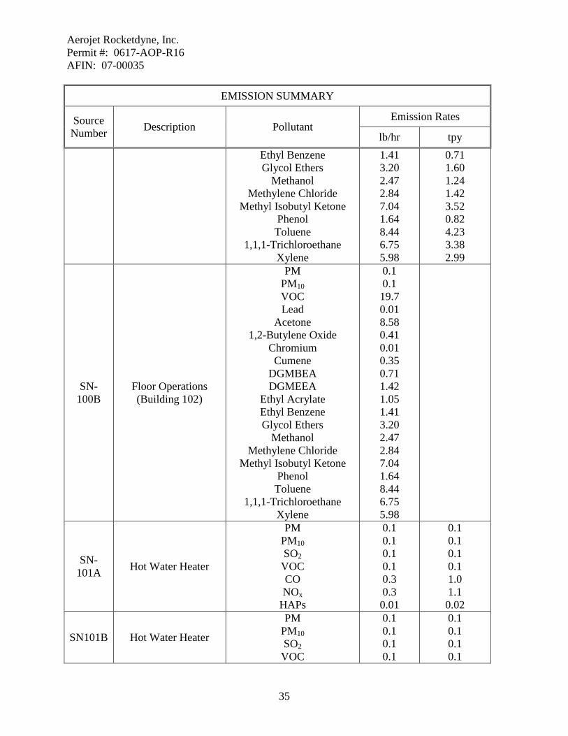
Emission Summary
The following table is a summary of emissions from the facility. This table, in itself, is not an enforceable condition of the permit.
EMISSION SUMMARY
Source Number Description Pollutant
Emission Rates
lb/hr tpy
Total Allowable Emissions
PM PM10 PM2.5 SO2 VOC CO
NOX Lead
16320.1 16320.1
See Note* 6.5
1521.6 11572.6 434.5 305.64
207 207
6.8
172.3 103.3 103.3 6.73
HAPs
Acetaldehyde Acrolein Benzene
1,2-Butylene Oxide 1,3 Butadiene
Cadmium Chlorine
Chromium Cumene
Diethylene Glycol Monobutyl Ether Acetate
0.1 0.1 2.7 5.44 0.1 2.71
207.12 23.93 4.8
8.62
0.1 0.1 0.2 1.73 0.1 0.08 7.83 0.64 1.68
1.86

Aerojet Rocketdyne, Inc. Permit #: 0617-AOP-R16 AFIN: 07-00035
15
EMISSION SUMMARY
Source Number Description Pollutant
Emission Rates
lb/hr tpy Diethylene Glycol
Monoethyl Ether Acetate Ethyl Acrylate Ethyl Benzene Formaldehyde
Hydrogen Chloride Hydrogen Fluoride
Methanol Methylene Chloride
Methyl Isobutyl Ketone Phenol
Tetrachloroethylene Toluene
1,1,1-Trichloroethane Trichloroethylene
Xylene HAPs
17.24 13.9 39.84 0.97
10894.7 38.02 61.44 107.18 141.76 19.86 12.53 155.56 158.33 32.2
152.54 1.12
3.61 4.83 9.33 0.5
145.4 0.8
19.08 26.02 36.62 4.4 2.6
44.95 39.56 6.68 37.63 0.77
Air Contaminants ***
Acetone Ammonia
HFC-245fa CFC-113
146.26 0.03 0.7 6.6
39.1 0.04 2.5 2.0
02A Boiler #1 Building M-
2 3.352 MMBTU/hr
PM PM10 SO2 VOC CO
NOX HAPs
0.1 0.1 0.1 0.1 0.3 0.4 0.01
0.2 0.2 0.1 0.1 1.3 1.5 0.01
02B Boiler #2 Building M-
2 3.352 MMBTU/hr
PM PM10 SO2 VOC CO
NOX HAPs
0.1 0.1 0.1 0.1 0.3 0.4 0.01
0.2 0.2 0.1 0.1 1.3 1.5 0.01
02C Boiler #4R
Building M-2 4.185 MMBTU/hr
PM PM10 SO2 VOC CO
0.1 0.1 0.1 0.1 0.4
0.2 0.2 0.1 0.2 1.6

Aerojet Rocketdyne, Inc. Permit #: 0617-AOP-R16 AFIN: 07-00035
16
EMISSION SUMMARY
Source Number Description Pollutant
Emission Rates
lb/hr tpy NOX HAPs
0.5 0.01
1.9 0.01
02D Boiler #6 Building M-
8 2.1 MMBTU/hr
PM PM10 SO2 VOC CO
NOX HAPs
0.1 0.1 0.1 0.1 0.2 0.3 0.01
0.1 0.1 0.1 0.1 0.8 1.0 0.01
02E Boiler #7 Building M-
8 2.1 MMBTU/hr
PM PM10 SO2 VOC CO
NOX HAPs
0.1 0.1 0.1 0.1 0.2 0.3 0.01
0.1 0.1 0.1 0.1 0.8 1.0 0.01
02F Boiler #8 Building M-
8 4.185 MMBTU/hr
PM PM10 SO2 VOC CO
NOX HAPs
0.1 0.1 0.1 0.1 0.4 0.5 0.01
0.2 0.2 0.1 0.2 1.6 1.9 0.01
02G Boiler #9 Building M-
2 4.185 MMBTU/hr
PM PM10 SO2 VOC CO
NOX HAPs
0.1 0.1 0.1 0.1 0.4 0.5 0.01
0.2 0.2 0.1 0.2 1.6 1.9 0.01
03A-G Rocket Test Facility
PM PM10 VOC CO
NOX Lead
Cadmium Chlorine
Chromium Hydrogen Chloride
-
48.7 48.7 2.5 44.5 0.5 1.5 0.01 0.3 0.11 35.1

Aerojet Rocketdyne, Inc. Permit #: 0617-AOP-R16 AFIN: 07-00035
17
EMISSION SUMMARY
Source Number Description Pollutant
Emission Rates
lb/hr tpy Hydrogen Fluoride 0.1
03A Rocket Test Facility Bay 15
PM PM10 VOC CO
NOX Lead
Cadmium Chlorine
Chromium Hydrogen Chloride Hydrogen Fluoride
1,900.0 1,900.0 100.0
1,765.5 16.5 58.8 0.46 12.0 4.2
1,400.0 4.1
03B Rocket Test Facility Bay 18
PM PM10 VOC CO
NOX Lead
Cadmium Chlorine
Chromium Hydrogen Chloride Hydrogen Fluoride
1,900.0 1,900.0 100.0
1,765.5 16.5 58.8 0.46 12.0 4.2
1,400.0 4.1
03C Rocket Test Facility Bay 45
PM PM10 VOC CO
NOX Lead
Cadmium Chlorine
Chromium Hydrogen Chloride Hydrogen Fluoride
7,600.0 7,600.0 400.0
7,062.0 66.0 58.8 0.46 48.0 4.2
5,600.0 16.2
03D Rocket Test Facility Bay 16
PM PM10 CO
NOX Hydrogen Chloride
45.7 45.7 14.7 0.1 1.6

Aerojet Rocketdyne, Inc. Permit #: 0617-AOP-R16 AFIN: 07-00035
18
EMISSION SUMMARY
Source Number Description Pollutant
Emission Rates
lb/hr tpy
03E Rocket Test Facility M-85
PM PM10 CO
NOX Hydrogen Chloride
45.7 45.7 14.7 0.1 1.6
03F Rocket Test Facility M-125
PM PM10 CO
NOX Hydrogen Chloride
45.7 45.7 14.7 0.1 1.6
SN-03G Rocket Test Facility Bay 49
PM PM10 VOC CO NOx Lead
Cadmium Chlorine
Chromium Hydrogen Chloride Hydrogen Fluoride
760.0 760.0 40.0 706.2 6.6 39.2 0.31 4.8 2.8
560.0 1.62
04 Thermal Treatment Facility
PM PM10 VOC CO
NOX Lead
Cadmium Chlorine
Chromium, Trivalent Chromium, Hexavalent
Hydrogen Chloride Hydrogen Fluoride
3,874.4 3,874.4 160.0 40.0 236.0 84.0 0.97 129.6 7.9 0.13
1,840.8 12.0
143.2 143.2 9.3 2.4 13.7 4.9 0.06 7.5 0.45 0.01 106.5 0.7
07 Liner Mixer and Spray Liner Machine VOC 17.0 2.2
11 Lacquer Preparation VOC
Acetone Methylene Chloride
40.1 40.1 40.1
5.1 5.1 5.1
12 Spray Painting Area PM PM10
0.1 0.1
0.1 0.1

Aerojet Rocketdyne, Inc. Permit #: 0617-AOP-R16 AFIN: 07-00035
19
EMISSION SUMMARY
Source Number Description Pollutant
Emission Rates
lb/hr tpy VOC Lead
Acetone Cumene
Ethyl Acrylate Ethyl Benzene
Methanol Methyl Isobutyl Ketone
Toluene Xylene
15.5 0.01 9.4 0.4 1.1 0.7 1.4 4.2 6.0 4.2
2.6 0.01 1.4 0.1 0.3 0.2 0.4 1.1 1.5 1.1
13 Ultrasonic Cleaner VOC 1,2-Butylene Oxide
0.2 0.01
0.3 0.01
19 Motor Case Cleaner VOC 1,2-Butylene Oxide
6.6 0.07
13.8 0.14
20A Solvent Wipe Room Building 2-SH-14 VOC 8.5 2.2
20B Solvent Wipe Room Building 2-SH-15 VOC 8.5
22 Mix Room VOC 8.5 4.3
24 Spray Paint Booth
PM PM10 VOC Lead
Acetone Chromium Cumene
Ethyl Acrylate Ethyl Benzene
Methanol Methyl Isobutyl Ketone
Toluene Xylene
0.1 0.1 53.5 0.01 11.2 0.01 1.4 4.2 2.8 5.6 16.8 23.8 16.8
0.1 0.1 7.6 0.01 2.1 0.01 0.3 0.8 0.6 1.1 3.2 4.5 3.2
SN-25A
Natural Gas Fired Boiler Unit #1
Building #47 2.35 MMBTU/hr
PM PM10 SO2 VOC CO
NOX HAPs
0.1 0.1 0.1 0.1 0.2 0.3 0.01
0.1 0.1 0.1 0.1 0.9 1.1 0.01

Aerojet Rocketdyne, Inc. Permit #: 0617-AOP-R16 AFIN: 07-00035
20
EMISSION SUMMARY
Source Number Description Pollutant
Emission Rates
lb/hr tpy
SN-25C
Natural Gas Fired Boiler Unit #3
Building #48 2.0 MMBTU/hr
PM PM10 SO2 VOC CO
NOX HAPs
0.1 0.1 0.1 0.1 0.2 0.2 0.01
0.1 0.1 0.1 0.1 0.8 0.9 0.01
SN-25E
Natural Gas Fired Boiler Unit #5
Building M-85 2.0 MMBTU/hr
PM PM10 SO2 VOC CO
NOX HAPs
0.1 0.1 0.1 0.1 0.2 0.2 0.01
0.1 0.1 0.1 0.1 0.8 0.9 0.01
SN-25F
Natural Gas Fired Boiler Unit #6
Building M-85 2.0 MMBTU/hr
PM PM10 SO2 VOC CO
NOX HAPs
0.1 0.1 0.1 0.1 0.2 0.2 0.01
0.1 0.1 0.1 0.1 0.8 0.9 0.01
28 Spray Liner Machine and Mixer Unit VOC 17.0 2.2
30 High Explosives Test Facility
PM PM10 VOC CO
NOX Lead
Cadmium Chlorine
Chromium, Trivalent Hydrogen Chloride
137.0 137.0 6.0
106.0 1.0 5.88 0.05 0.72 0.42 89.1
5.5 5.5 0.3 4.3 0.1 0.24 0.01 0.03 0.02 3.8
36 Vapor Degreaser VOC 1,2-Butylene Oxide
1.1 0.02
8.3 0.09
37A Motor Case Cleaning
(Prior to Grit Blasting) Building 2-SH-2
VOC 4.3 1.5
37B Motor Case Cleaning (Prior to Grit Blasting) VOC 4.3

Aerojet Rocketdyne, Inc. Permit #: 0617-AOP-R16 AFIN: 07-00035
21
EMISSION SUMMARY
Source Number Description Pollutant
Emission Rates
lb/hr tpy Building 2-SH-14
38A Motor Case Cleaning (After Grit Blasting)
Building 2-SH-2 VOC 4.3 1.5
38B Motor Case Cleaning (After Grit Blasting)
Building 2-SH-14 VOC 4.3
39A Adhesive Primer
Operations Building 2-SH-14
VOC 1,2-Butylene Oxide
Ethyl Benzene Formaldehyde
Methanol Methyl Isobutyl Ketone
Tetrachloroethylene Toluene
1,1,1-Trichloroethane Trichloroethylene
Xylene
10.0 0.29 1.44 0.03 1.2 3.8 0.9 1.5 3.2 2.3 4.9
3.0 0.12 0.58 0.02 0.46 1.5 0.35 0.58 1.27 0.92 1.96
39B Adhesive Primer
Operations Building 2-SH-15
VOC 1,2-Butylene Oxide
Ethyl Benzene Formaldehyde
Methanol Methyl Isobutyl Ketone
Tetrachloroethylene Toluene
1,1,1-Trichloroethane Trichloroethylene
Xylene
10.0 0.29 1.44 0.03 1.2 3.8 0.9 1.5 3.2 2.3 4.9
40A Adhesive Operations Building 2-SH-14
VOC 1,2-Butylene Oxide
Ethyl Benzene Formaldehyde
Methanol Methyl Isobutyl Ketone
Tetrachloroethylene Toluene
1,1,1-Trichloroethane Trichloroethylene
10.0 0.29 1.44 0.03 1.2 3.8 0.9 1.5 3.2 2.3
3.0 0.12 0.58 0.02 0.46 1.5 0.35 0.58 1.27 0.92

Aerojet Rocketdyne, Inc. Permit #: 0617-AOP-R16 AFIN: 07-00035
22
EMISSION SUMMARY
Source Number Description Pollutant
Emission Rates
lb/hr tpy Xylene 4.9 1.96
40B Adhesive Operations Building 2-SH-15
VOC 1,2-Butylene Oxide
Ethyl Benzene Formaldehyde
Methanol Methyl Isobutyl Ketone
Tetrachloroethylene Toluene
1,1,1-Trichloroethane Trichloroethylene
Xylene
10.0 0.29 1.44 0.03 1.2 3.8 0.9 1.5 3.2 2.3 4.9
41A Adhesive Barrier
Coating Operations Building 2-SH-14
VOC 1,2-Butylene Oxide
Ethyl Benzene Formaldehyde
Methanol Methyl Isobutyl Ketone
Tetrachloroethylene Toluene
1,1,1-Trichloroethane Trichloroethylene
Xylene
10.0 0.29 1.44 0.03 1.2 3.8 0.9 1.5 3.2 2.3 4.9
3.0 0.12 0.58 0.02 0.46 1.5 0.35 0.58 1.27 0.92 1.96
41B Adhesive Barrier
Coating Operations Building 2-SH-15
VOC 1,2-Butylene Oxide
Ethyl Benzene Formaldehyde
Methanol Methyl Isobutyl Ketone
Tetrachloroethylene Toluene
1,1,1-Trichloroethane Trichloroethylene
Xylene
10.0 0.29 1.44 0.03 1.2 3.8 0.9 1.5 3.2 2.3 4.9
42 Spray Liner Machine VOC 8.5 1.1
43 Spray Paint Booth
PM PM10 VOC Lead
0.1 0.1 22.5 0.01
0.1 0.1 8.5 0.01
Aerojet Rocketdyne, Inc. Permit #: 0617-AOP-R16 AFIN: 07-00035
23
EMISSION SUMMARY
Source Number Description Pollutant
Emission Rates
lb/hr tpy Acetone
Chromium Cumene
Ethyl Acrylate Ethyl Benzene
Methanol Methyl Isobutyl Ketone
Toluene Xylene
5.6 0.01 0.7 2.1 1.4 2.8 8.4 11.9 8.4
2.8 0.01 0.4 1.1 0.7 1.4 4.2 6.0 4.2
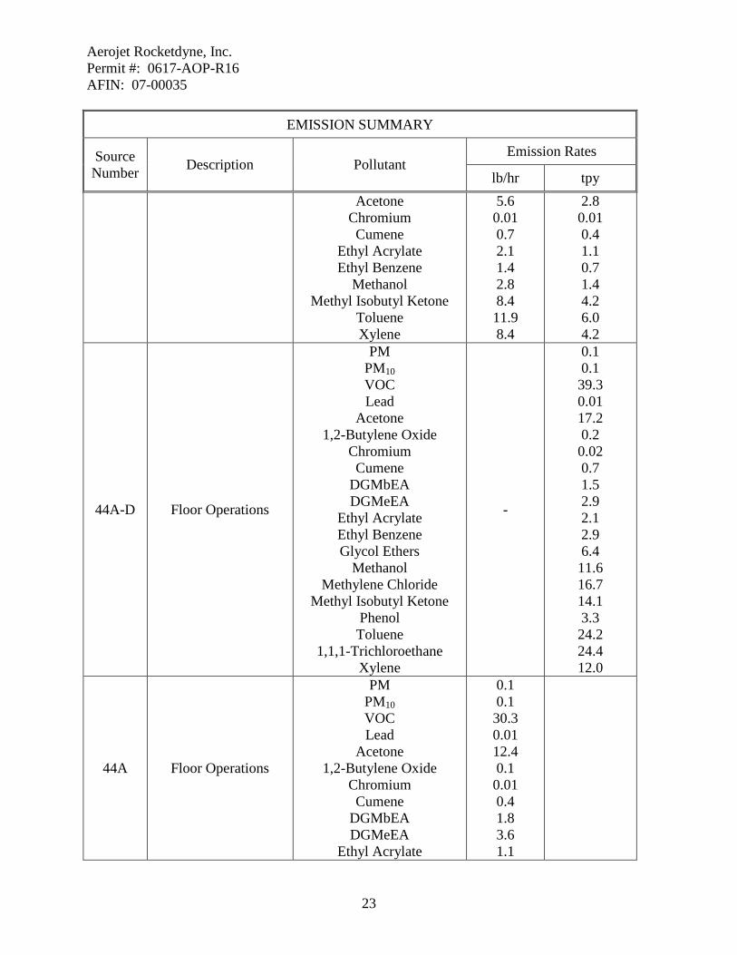
44A-D Floor Operations
PM PM10 VOC Lead
Acetone 1,2-Butylene Oxide
Chromium Cumene
DGMbEA DGMeEA
Ethyl Acrylate Ethyl Benzene Glycol Ethers
Methanol Methylene Chloride
Methyl Isobutyl Ketone Phenol Toluene
1,1,1-Trichloroethane Xylene
-
0.1 0.1 39.3 0.01 17.2 0.2 0.02 0.7 1.5 2.9 2.1 2.9 6.4 11.6 16.7 14.1 3.3 24.2 24.4 12.0
44A Floor Operations
PM PM10 VOC Lead
Acetone 1,2-Butylene Oxide
Chromium Cumene
DGMbEA DGMeEA
Ethyl Acrylate
0.1 0.1 30.3 0.01 12.4 0.1 0.01 0.4 1.8 3.6 1.1

Aerojet Rocketdyne, Inc. Permit #: 0617-AOP-R16 AFIN: 07-00035
24
EMISSION SUMMARY
Source Number Description Pollutant
Emission Rates
lb/hr tpy Ethyl Benzene Glycol Ethers
Methanol Methylene Chloride
Methyl Isobutyl Ketone Phenol Toluene
1,1,1-Trichloroethane Xylene
2.5 8.0 7.5 12.6 11.3 4.1 15.8 22.3 8.7
44B Floor Operations
PM PM10 VOC Lead
Acetone 1,2-Butylene Oxide
Chromium Cumene
DGMbEA DGMeEA
Ethyl Acrylate Ethyl Benzene Glycol Ethers
Methanol Methylene Chloride
Methyl Isobutyl Ketone Phenol Toluene
1,1,1-Trichloroethane Xylene
0.1 0.1 30.3 0.01 12.4 0.1 0.01 0.4 1.8 3.6 1.1 2.5 8.0 7.5 12.6 11.3 4.1 15.8 22.3 8.7
44C Floor Operations
PM PM10 VOC Lead
Acetone 1,2-Butylene Oxide
Chromium Cumene
DGMbEA DGMeEA
Ethyl Acrylate
0.1 0.1 30.3 0.01 12.4 0.1 0.01 0.4 1.8 3.6 1.1

Aerojet Rocketdyne, Inc. Permit #: 0617-AOP-R16 AFIN: 07-00035
25
EMISSION SUMMARY
Source Number Description Pollutant
Emission Rates
lb/hr tpy Ethyl Benzene Glycol Ethers
Methanol Methylene Chloride
Methyl Isobutyl Ketone Phenol Toluene
1,1,1-Trichloroethane Xylene
2.5 8.0 7.5 12.6 11.3 4.1 15.8 22.3 8.7
44D Floor Operations
PM PM10 VOC Lead
Acetone 1,2-Butylene Oxide
Chromium Cumene
DGMbEA DGMeEA
Ethyl Acrylate Ethyl Benzene Glycol Ethers
Methanol Methylene Chloride
Methyl Isobutyl Ketone Phenol Toluene
1,1,1-Trichloroethane Xylene
0.1 0.1 30.3 0.01 12.4 0.1 0.01 0.4 1.8 3.6 1.1 2.5 8.0 7.5 12.6 11.3 4.1 15.8 22.3 8.7
47 Foam-Blowing Operations
VOC HFC-245fa
8.5 0.7
1.3 2.5
48A Phenolic Molding Operations
VOC Ammonia
Formaldehyde Phenol
0.1 0.01 0.01 0.06
0.2 0.02 0.01 0.14
48A Phenolic Molding Operations
VOC Ammonia
Formaldehyde Phenol
0.1 0.01 0.01 0.06
Aerojet Rocketdyne, Inc. Permit #: 0617-AOP-R16 AFIN: 07-00035
26
EMISSION SUMMARY
Source Number Description Pollutant
Emission Rates
lb/hr tpy
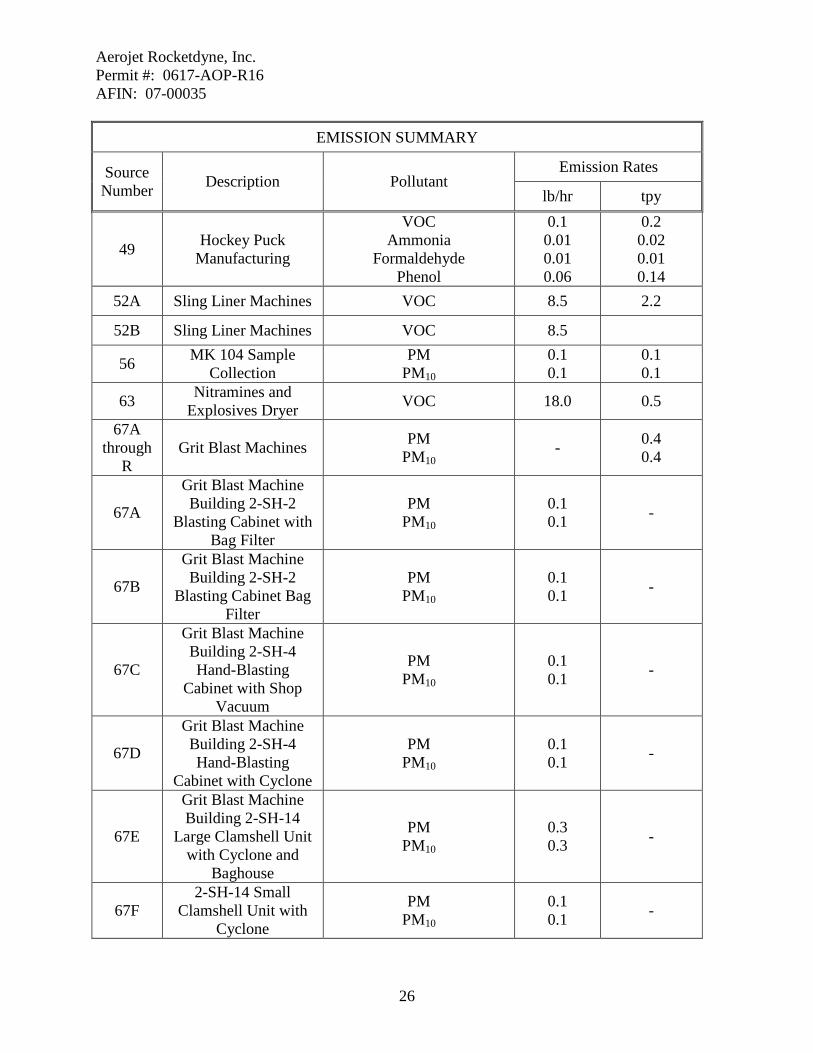
49 Hockey Puck Manufacturing
VOC Ammonia
Formaldehyde Phenol
0.1 0.01 0.01 0.06
0.2 0.02 0.01 0.14
52A Sling Liner Machines VOC 8.5 2.2
52B Sling Liner Machines VOC 8.5
56 MK 104 Sample Collection
PM PM10
0.1 0.1
0.1 0.1
63 Nitramines and Explosives Dryer VOC 18.0 0.5
67A through
R Grit Blast Machines PM
PM10 - 0.4
0.4
67A
Grit Blast Machine Building 2-SH-2
Blasting Cabinet with Bag Filter
PM PM10
0.1 0.1 -
67B
Grit Blast Machine Building 2-SH-2
Blasting Cabinet Bag Filter
PM PM10
0.1 0.1 -
67C
Grit Blast Machine Building 2-SH-4 Hand-Blasting
Cabinet with Shop Vacuum
PM PM10
0.1 0.1 -
67D
Grit Blast Machine Building 2-SH-4 Hand-Blasting
Cabinet with Cyclone
PM PM10
0.1 0.1 -
67E
Grit Blast Machine Building 2-SH-14
Large Clamshell Unit with Cyclone and
Baghouse
PM PM10
0.3 0.3 -
67F 2-SH-14 Small
Clamshell Unit with Cyclone
PM PM10
0.1 0.1 -

Aerojet Rocketdyne, Inc. Permit #: 0617-AOP-R16 AFIN: 07-00035
27
EMISSION SUMMARY
Source Number Description Pollutant
Emission Rates
lb/hr tpy
67G
Grit Blast Machine Building 2-SH-14
Hand-Blasting Cabinet with Shop
Vacuum
PM PM10
0.1 0.1 -
67H
Grit Blast Machine Building 2-SH-14
Hand-Blasting Cabinet with Shop
Vacuum
PM PM10
0.1 0.1 -
67I
Grit Blast Machine Building 2-SH-14
Hand-Blasting Cabinet with Cyclone
PM PM10
0.1 0.1 -
67J
Grit Blast Machine Building 33 Large
Blasting Machine with Baghouse
PM PM10
0.1 0.1 -
67K
Grit Blast Machine Building 36 Hand-
Blasting Cabinet with Bag Filter
PM PM10
0.3 0.3 -
67L
Grit Blast Machine Building M-2 Grit Blasting Machine
Shop Vacuum
PM PM10
0.2 0.2
- -
67M
Grit Blast Machine Building M-2 Sand
Blasting Machine with Bag Filter
67N M-2 Grit Blasting Machine with Dust
Collector
PM PM10
0.3 0.3 -
67P
Grit Blast Machine Building M-82 Large
Blasting Machine with Baghouse
PM PM10
0.3 0.3 -
67Q Grit Blast Machine
Building M-85 Hand-Blasting Cabinet with
PM PM10
0.3 0.3 -

Aerojet Rocketdyne, Inc. Permit #: 0617-AOP-R16 AFIN: 07-00035
28
EMISSION SUMMARY
Source Number Description Pollutant
Emission Rates
lb/hr tpy Baghouse
67R
Grit Blast Machine Building M-85 Hand-Blasting Cabinet with
Baghouse
PM PM10
0.3 0.3 -
69C Building M-125 2.1 MMBTU/hr
PM PM10 SO2 VOC CO
NOX HAPs
0.1 0.1 0.1 0.1 0.2 0.3 0.01
0.1 0.1 0.1 0.1 0.8 1.0 0.01
69D Building M-125 2.1 MMBTU/hr
PM PM10 SO2 VOC CO
NOX HAPs
0.1 0.1 0.1 0.1 0.2 0.3 0.01
0.1 0.1 0.1 0.1 0.8 1.0 0.01
69E Building 2-SH-2 2.0 MMBTU/hr
PM PM10 SO2 VOC CO
NOX HAPs
0.1 0.1 0.1 0.1 0.2 0.2 0.01
0.1 0.1 0.1 0.1 0.8 0.9 0.01
69F Building 2-SH-15 1.34 MMBTU/hr
PM PM10 SO2 VOC CO
NOX HAPs
0.1 0.1 0.1 0.1 0.2 0.2 0.01
0.1 0.1 0.1 0.1 0.6 0.7 0.01
69G Building 2-SH-15 1.34 MMBTU/hr
PM PM10 SO2 VOC CO
NOX
0.1 0.1 0.1 0.1 0.2 0.2
0.1 0.1 0.1 0.1 0.6 0.7

Aerojet Rocketdyne, Inc. Permit #: 0617-AOP-R16 AFIN: 07-00035
29
EMISSION SUMMARY
Source Number Description Pollutant
Emission Rates
lb/hr tpy HAPs 0.01 0.01
69H Building 2-SH-15 1.34 MMBTU/hr
PM PM10 SO2 VOC CO
NOX HAPs
0.1 0.1 0.1 0.1 0.2 0.2 0.01
0.1 0.1 0.1 0.1 0.6 0.7 0.01
71 Gasoline Storage Tank
VOC Benzene
Ethyl Benzene Hexane
Naphthalene Toluene Xylene
44.1 2.6 1.6 2.0 1.4 12.8 7.7
0.9 0.1 0.1 0.1 0.1 0.3 0.2
72 Diesel Fuel Storage Tanks VOC 0.1 0.1
73 Nitramines and Explosive Grinder
PM PM10
0.1 0.1
0.1 0.1
74 Solvent Wipe Room VOC 8.5 2.2
75 Sling Liner Machine VOC 8.5 1.1
76A Adhesive Primer Operations
PM PM10 VOC Lead
1,2-Butylene Oxide Ethyl Benzene Formaldehyde
Methanol Methyl Isobutyl Ketone
Tetrachloroethylene Toluene
1,1,1-Trichloroethane Trichloroethylene
Xylene
0.1 0.1 14.3 0.01 0.3 1.5 0.1 1.2 3.8 0.9 1.5 3.2 2.3 4.9
0.1 0.1 3.0 0.01 0.2 0.6 0.1 0.5 1.5 0.4 0.6 1.3 1.0 2.0
76B Adhesive Primer Operations
PM PM10 VOC
0.1 0.1 14.3

Aerojet Rocketdyne, Inc. Permit #: 0617-AOP-R16 AFIN: 07-00035
30
EMISSION SUMMARY
Source Number Description Pollutant
Emission Rates
lb/hr tpy Lead
1,2-Butylene Oxide Ethyl Benzene Formaldehyde
Methanol Methyl Isobutyl Ketone
Tetrachloroethylene Toluene
1,1,1-Trichloroethane Trichloroethylene
Xylene
0.01 0.3 1.5 0.1 1.2 3.8 0.9 1.5 3.2 2.3 4.9
77A Adhesive Operations
PM PM10 VOC Lead
1,2-Butylene Oxide Ethyl Benzene Formaldehyde
Methanol Methyl Isobutyl Ketone
Tetrachloroethylene Toluene
1,1,1-Trichloroethane Trichloroethylene
Xylene
0.1 0.1 14.3 0.01 0.3 1.5 0.1 1.2 3.8 0.9 1.5 3.2 2.3 4.9
0.1 0.1 3.0 0.01 0.2 0.6 0.1 0.5 1.5 0.4 0.6 1.3 1.0 2.0
77B Adhesive Operations
PM PM10 VOC Lead
1,2-Butylene Oxide Ethyl Benzene Formaldehyde
Methanol Methyl Isobutyl Ketone
Tetrachloroethylene Toluene
1,1,1-Trichloroethane Trichloroethylene
Xylene
0.1 0.1 14.3 0.01 0.3 1.5 0.1 1.2 3.8 0.9 1.5 3.2 2.3 4.9

Aerojet Rocketdyne, Inc. Permit #: 0617-AOP-R16 AFIN: 07-00035
31
EMISSION SUMMARY
Source Number Description Pollutant
Emission Rates
lb/hr tpy
78A Adhesive Barrier Coating Operation
PM PM10 VOC Lead
1,2-Butylene Oxide Ethyl Benzene Formaldehyde
Methanol Methyl Isobutyl Ketone
Tetrachloroethylene Toluene
1,1,1-Trichloroethane Trichloroethylene
Xylene
0.1 0.1 14.3 0.01 0.3 1.5 0.1 1.2 3.8 0.9 1.5 3.2 2.3 4.9
0.1 0.1 3.0 0.01 0.2 0.6 0.1 0.5 1.5 0.4 0.6 1.3 1.0 2.0
78B Adhesive Barrier Coating Operation
PM PM10 VOC Lead
1,2-Butylene Oxide Ethyl Benzene Formaldehyde
Methanol Methyl Isobutyl Ketone
Tetrachloroethylene Toluene
1,1,1-Trichloroethane Trichloroethylene
Xylene
0.1 0.1 14.3 0.01 0.3 1.5 0.1 1.2 3.8 0.9 1.5 3.2 2.3 4.9
80 Warhead Coating Operation
VOC CFC-113
1.0 6.6
0.3 2.0
81 Diesel-Powered Pump Rocket at Motor Case
Washout Facility
PM PM10 SO2 VOC CO
NOX Acetaldehyde
Acrolein Benzene
1,3 Butadiene
0.7 0.7 0.7 0.8 2.0 9.2 0.1 0.1 0.1 0.1
2.9 2.9 2.7 3.3 8.7 40.0 0.1 0.1 0.1 0.1

Aerojet Rocketdyne, Inc. Permit #: 0617-AOP-R16 AFIN: 07-00035
32
EMISSION SUMMARY
Source Number Description Pollutant
Emission Rates
lb/hr tpy Formaldehyde
PAHs Toluene Xylene
0.1 0.1 0.1 0.1
0.1 0.1 0.1 0.1
84 Warhead
Manufacturing Operations
PM PM10 SO2 VOC CO
NOX HAPs
0.1 0.1 0.1 10.1 0.3 0.4 0.01
0.2 0.2 0.1 1.7 1.3 1.7 0.01
85 Motor Case Cleaning Operations
VOC Methylene Chloride
1,1,1-Trichloroethane
17.0 11.0 10.9
2.2 2.8 2.8
86 Emergency Power Generator
PM PM10 SO2 VOC CO NOx
HAPs
0.1 0.1 0.1 0.1 0.7 0.4 0.01
0.1 0.1 0.1 0.1 0.2 0.1 0.01
87 Emergency Power Generator
PM PM10 SO2 VOC CO NOx
HAPs
0.1 0.1 0.1 0.1 7.4 4.4 0.01
0.1 0.1 0.1 0.1 1.9 1.1 0.01
89 Emergency Power Generator Building
M-142
PM PM10 SO2 VOC CO NOx
HAPs
0.1 0.1 0.1 0.1 5.9 3.5 0.01
0.1 0.1 0.1 0.1 1.5 0.9 0.01
90 Emergency Power Generator Building
M-8
PM PM10 SO2 VOC CO
0.1 0.1 0.1 0.1 4.2
0.1 0.1 0.1 0.1 1.1
Aerojet Rocketdyne, Inc. Permit #: 0617-AOP-R16 AFIN: 07-00035
33
EMISSION SUMMARY
Source Number Description Pollutant
Emission Rates
lb/hr tpy NOx
HAPs 2.5 0.01
0.7 0.01
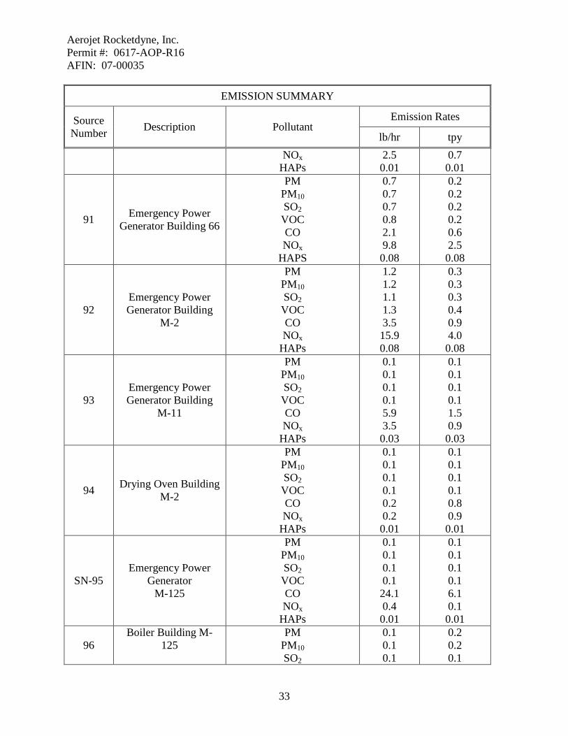
91 Emergency Power Generator Building 66
PM PM10 SO2 VOC CO NOx
HAPS
0.7 0.7 0.7 0.8 2.1 9.8 0.08
0.2 0.2 0.2 0.2 0.6 2.5 0.08
92 Emergency Power Generator Building
M-2
PM PM10 SO2 VOC CO NOx
HAPs
1.2 1.2 1.1 1.3 3.5 15.9 0.08
0.3 0.3 0.3 0.4 0.9 4.0 0.08
93 Emergency Power Generator Building
M-11
PM PM10 SO2 VOC CO NOx
HAPs
0.1 0.1 0.1 0.1 5.9 3.5 0.03
0.1 0.1 0.1 0.1 1.5 0.9 0.03
94 Drying Oven Building M-2
PM PM10 SO2 VOC CO NOx
HAPs
0.1 0.1 0.1 0.1 0.2 0.2 0.01
0.1 0.1 0.1 0.1 0.8 0.9 0.01
SN-95 Emergency Power
Generator M-125
PM PM10 SO2 VOC CO NOx
HAPs
0.1 0.1 0.1 0.1 24.1 0.4 0.01
0.1 0.1 0.1 0.1 6.1 0.1 0.01
96 Boiler Building M-
125
PM PM10 SO2
0.1 0.1 0.1
0.2 0.2 0.1

Aerojet Rocketdyne, Inc. Permit #: 0617-AOP-R16 AFIN: 07-00035
34
EMISSION SUMMARY
Source Number Description Pollutant
Emission Rates
lb/hr tpy VOC CO
NOX HAPs
0.1 0.4 0.5 0.1
0.2 1.6 1.9 0.1
97 Boiler Building M-8
PM PM10 SO2 VOC CO
NOX HAPs
0.1 0.1 0.1 0.1 0.4 0.5 0.1
0.2 0.2 0.1 0.2 1.6 1.9 0.1
SN-98 Spray Liner Operation Building M-125
PM PM10 VOC
Acetone
0.1 0.1 15.5 13.2
0.1 0.1 6.9 6.2
SN-99 Spray Liner Machine (Building 102)
PM PM10 VOC Lead
1,2-Butylene Oxide Ethyl Benzene Formaldehyde
Methanol Methyl Isobutyl Ketone
Tetrachloroethylene Toluene
1,1,1-Trichloroethane Trichloroethylene
Xylene
0.1 0.1 28.5 0.01 0.58 2.88 0.06 2.30 7.48 1.73 2.88 6.33 4.60 9.78
0.1 0.1 4.0 0.01 0.12 0.58 0.02 0.46 1.50 0.35 0.58 1.27 0.92 1.96
SN100A Floor Operations (Building 101)
PM PM10 VOC Lead
Acetone 1,2-Butylene Oxide
Chromium Cumene
DGMBEA DGMEEA
Ethyl Acrylate
0.1 0.1 19.7 0.01 8.58 0.41 0.01 0.35 0.71 1.42 1.05
0.1 0.1 9.9 0.01 4.30 0.21 0.01 0.18 0.36 0.71 0.53
Aerojet Rocketdyne, Inc. Permit #: 0617-AOP-R16 AFIN: 07-00035
35
EMISSION SUMMARY
Source Number Description Pollutant
Emission Rates
lb/hr tpy Ethyl Benzene Glycol Ethers
Methanol Methylene Chloride
Methyl Isobutyl Ketone Phenol Toluene
1,1,1-Trichloroethane Xylene
1.41 3.20 2.47 2.84 7.04 1.64 8.44 6.75 5.98
0.71 1.60 1.24 1.42 3.52 0.82 4.23 3.38 2.99
SN-100B
Floor Operations (Building 102)
PM PM10 VOC Lead
Acetone 1,2-Butylene Oxide
Chromium Cumene
DGMBEA DGMEEA
Ethyl Acrylate Ethyl Benzene Glycol Ethers
Methanol Methylene Chloride
Methyl Isobutyl Ketone Phenol Toluene
1,1,1-Trichloroethane Xylene
0.1 0.1 19.7 0.01 8.58 0.41 0.01 0.35 0.71 1.42 1.05 1.41 3.20 2.47 2.84 7.04 1.64 8.44 6.75 5.98
SN-101A Hot Water Heater
PM PM10 SO2 VOC CO NOx
HAPs
0.1 0.1 0.1 0.1 0.3 0.3 0.01
0.1 0.1 0.1 0.1 1.0 1.1 0.02
SN101B Hot Water Heater
PM PM10 SO2 VOC
0.1 0.1 0.1 0.1
0.1 0.1 0.1 0.1

Aerojet Rocketdyne, Inc. Permit #: 0617-AOP-R16 AFIN: 07-00035
36
EMISSION SUMMARY
Source Number Description Pollutant
Emission Rates
lb/hr tpy CO NOx
HAPs
0.3 0.3 0.01
1.0 1.1 0.02
SN-102 Emergency Power
Generator (Building 101)
PM PM10 SO2 VOC CO NOx
HAPs
0.1 0.1 0.1 0.2 13.1 7.8 0.37
0.1 0.1 0.1 0.1 3.8 2.0 0.09
SN-103 Emergency Power
Generator (Building 102)
PM PM10 SO2 VOC CO NOx
HAPs
0.1 0.1 0.1 0.1 4.2 2.5 0.12
0.1 0.1 0.1 0.1 1.1 0.7 0.03
SN-104 Propellant Cutting
Operation (Building C39)
PM PM10
0.1 0.1
0.1 0.1
105 NG Emergency
Generator at 2-SH-9
PM PM10 SO2 VOC CO NOx
HAPs
0.1 0.1 0.1 0.4 1.7 12.2 0.01
0.1 0.1 0.1 0.1 0.5 3.1 0.01
106 Diesel Emergency
generator at M-14
PM PM10 SO2 VOC CO NOx
HAPs
0.9 0.9 0.9 1.1 2.7 12.5 0.01
0.5 0.5 0.5 0.6 1.4 6.3 0.01
*PM2.5 limits are source specific, if required. Not all sources have PM2.5 limits. **HAPs included in the VOC totals. Other HAPs are not included in any other totals unless specifically stated. ***Air Contaminants such as ammonia, acetone, and certain halogenated solvents are not VOCs or HAPs.

Aerojet Rocketdyne, Inc. Permit #: 0617-AOP-R16 AFIN: 07-00035
37
SECTION III: PERMIT HISTORY Permits 538-A and 617-A were issued to Atlantic Research in 1979 and 1980 for the installation of a facility in Highland Industrial Park to manufacture rocket propellants and the assembly of rocket motors. Permit 617-AR-1 was issued on September 23, 1983. This permit allowed for installation of additional facilities to re-manufacture rocket motors from the U.S. Army Red River Depot in Texarkana. Permit 617-AR-2 was issued on April 25, 1989. It allowed for production of solid propellant rocket motors and new facilities for painting rocket motor cases. Permit 617-AR-3 was issued on April 18, 1990. This permit allowed for construction of a new facility to be used to conduct acceptance tests for military and commercial high explosives. In 1992, ARC submitted an application for modification of its existing SIP permit. At that time, a number of significant process changes, including additional emission sources, were proposed for the East Camden facility. In June 1992, a draft air permit, 617-AR-4, was issued. ARC submitted comments on the draft in July 1992. A final permit was never issued. In May 1996, a minor modification of 617-AR-3 was approved. It authorized production of the Sidewinder Missile at the East Camden facility. New sources SN-37 through SN-45 were added to the permit. In October 1997, another minor modification of 617-AR-3 was approved. It authorized production of the AMRAAM warhead (SN-80) and the installation of a new grit blast machine (SN-67) at Building 2-SH-14. In May 1998, a third minor modification of 617-AR-3 was approved. It authorized installation of a diesel-powered pump (SN-81). This equipment was part of a new facility for the reclamation of rocket motor cases. In September 1998, a fourth minor modification was approved. It authorized construction of a new facility for the manufacture of air bag propellants (SN-82). In February 1999, a de minimis change to 617-AR-3 was approved. It authorized production of the PAC-2 Missile. New sources SN-74, SN-75, and SN-79 were added to the permit and SN-67 was modified. In March 1999, a second de minimis change was approved. It authorized production of the Advanced Tomahawk Missile at the facility. New source SN-83 was added to the permit and Sources SN-39 through SN-42 were modified.

Aerojet Rocketdyne, Inc. Permit #: 0617-AOP-R16 AFIN: 07-00035
38
On December 3, 2001, air permit 617-AOP-R0 was issued to ARC. This permit allowed for installation of the new Advanced Tomahawk production program, for modifications to the PAC-2 manufacturing operations, and for expansion of the air bag propellant and component manufacturing operations. This was also the first Title V Operating Permit issued to this facility. On October 10, 2002, air permit 617-AOP-R1 was issued to Atlantic Research Corporation. This minor modification application allowed for production of the Supersonic Sea-Skimming Target Rocket (SSST) Motor and to add an insignificant activity. A proposed new vent for an existing cutting/grinding operation was also added to the list of insignificant activities. Emissions increases were 1.3 tons per year of carbon monoxide and 0.02 tons per year of hydrogen fluoride. On May 13, 2003, Atlantic Research Corporation was granted authorization to relocate the Thermal Treatment Facility (SN-04) to a new site within the East Camden facility. There was no change in throughput or emissions. On July 7, 2003, air permit 0617-AOP-R2 was issued to Atlantic Research Corporation. This minor modification application allowed for a replacement of a 1.7 MMBTU/hr boiler in SN-02 with a new 3.352 MMBTU/hr boiler. On August 21, 2003, air permit 0617-AOP-R2 was administratively amended to add a new building to SN-82. There was no change in emissions. On September 9, 2003, Atlantic Research Corporation was granted authorization to replace two 1.7 MMBTU/hr boilers at Building M-2 with a 3.352 MMBTU/hr unit (SN-02). There was no change in overall fuel capacity or emissions. On October 4, 2003, air permit 0617-AOP-R2 was transferred from Atlantic Research Corporation to Aerojet-General Corporation. On July 15, 2004, air permit 0617-AOP-R2 was administratively amended to add two insignificant activities. These activities were the Six-Bladed Saw, Camfer, and Drill Machine and the Composite Case Grinding Machine. There was no change in emissions. On June 29, 2005, air permit 0617-AOP-R3 was issued to Aerojet – General Corporation. This permit involved several minor modifications for this facility. They were the following:
1. Production of a new propellant, ARCOMP 408, at the facility. This product is an ignition material for automobile air bag inflators. As part of the ARCOMP 408 program, three additional production buildings (70, 71, and 74) were installed at the East Camden facility. These units are considered part of the New Air Bag Manufacturing Operations (SN-82). Production of ARCOMP 408 did not change any of the currently permitted emission rates.

Aerojet Rocketdyne, Inc. Permit #: 0617-AOP-R16 AFIN: 07-00035
39
2. An increase in the throughput of the waste air bag propellants burned in the Thermal Treatment Facility (SN-04). Throughput was increased by 25,000 lb/year. This change increased PM and PM10 by 6.04 tons per year, NOX by 0.01 tons per year, and Hydrogen Chloride by 0.01 tons per year.
3. Correct the number of boilers listed in the group Process Boilers (SN-25). During
an internal compliance audit, Aerojet determined that the inventory of gas-fired process equipment used to prepare the original Operating Permit application was not accurate. A total of 7, rather than 4, boilers should have been included. The correct heat input capacity of the equipment is 10.06 MMBTU/hr instead of 4.20.
4. Install a new Grit Blast Machine as part of SN-67. In addition, the existing Liner
Spray Machine (SN-28) was to be replaced with an equivalent unit. On December 1, 2005, air permit 0617-AOP-R4 was issued to Aerojet- General Corporation. This minor modification application allowed for installation of new processes and equipment for the production of warheads and ordnance at Building M-11 (SN-84). These items included two coating operations (application of asphalt and wax liners), two propane-fired “melter/applicator machines,” and a natural gas-fired boiler. This change increased PM by 0.2 tons per year, SO2 by 0.1 tons per year, VOCs by 1.7 tons per year, CO by 1.3 tons per year, and NOX by 1.7 tons per year. This permit also added two steam-heated ovens to the Insignificant Activities section. On April 3, 2006, air permit 0617-AOP-R5 was issued to Aerojet - General Corporation. This minor modification application allowed for processing new rocket propellants that contain two hazardous air pollutants (Cadmium and Chromium) during the testing and treatment activities at the Rocket Test Facility (SN-03), the Thermal Treatment Facility (SN-04), and the High Explosives Test Facility (SN-30). In addition, Aerojet proposed to install a new spray liner machine (SN-07) and grit blast machine (SN-67) to support multiple rocket motor manufacturing programs. Finally, Aerojet proposed to implement new motor case cleaning activities (SN-85) to support several production programs. This included construction of a solvent wipe room and installation of a motor case flush-cleaning apparatus. The rocket propellant part of this modification resulted in permitted emissions increases of 0.05 tpy of Cadmium, 0.01 tpy of Chlorine, 0.54 tpy of Chromium, and 0.01 tpy of Hydrogen Chloride and permitted emissions decrease of 0.68 tpy of lead and 0.32 tpy of 1,3 Dioxolane. The new SN-85 part of this modification resulted in permitted increases of 1.6 tpy of VOC, 1.58 tpy of Methylene Chloride, 1.58 tpy of Methyl Ethyl Ketone, and 1.58 tpy of 1,1,1-Trichloroethane. On July 3, 2006, air permit 0617-AOP-R6 was issued to Aerojet – General Corporation. This minor modification was issued to replace one of the two natural gas-fired process boilers at Building 48 (SN-25). The new unit has a heat input capacity of 2.00 MMBTU/hr and replaces the 1.55 MMBTU/hr boiler. In addition, the source description for SN-02 was corrected. Increases from this modification were 0.2 tons per year of CO and 0.2 tons per year of NOX. Permit 617-AOP-R7 was issued on January 7, 2007. This modification is the first Title V Permit renewal for this facility. In addition, the facility made the following changes:
Aerojet Rocketdyne, Inc. Permit #: 0617-AOP-R16 AFIN: 07-00035
40
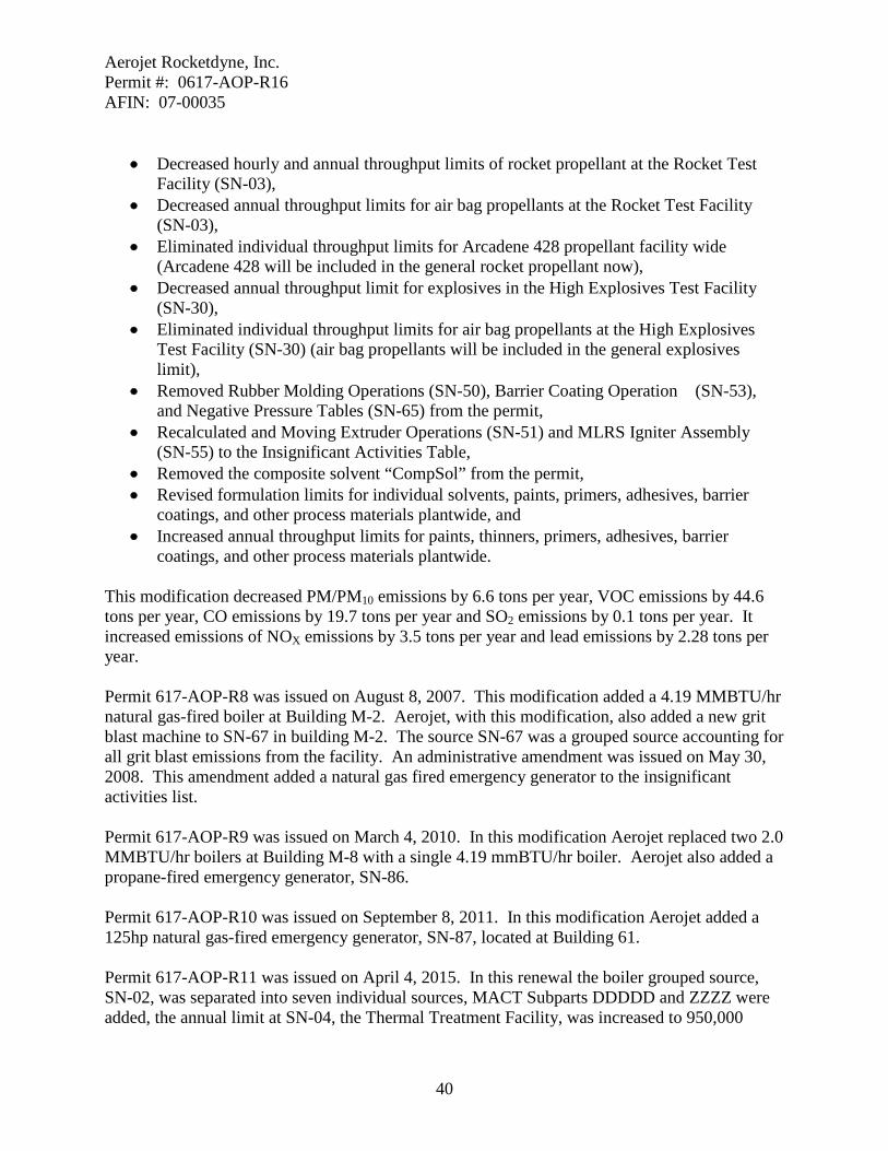
• Decreased hourly and annual throughput limits of rocket propellant at the Rocket Test
Facility (SN-03), • Decreased annual throughput limits for air bag propellants at the Rocket Test Facility
(SN-03), • Eliminated individual throughput limits for Arcadene 428 propellant facility wide
(Arcadene 428 will be included in the general rocket propellant now), • Decreased annual throughput limit for explosives in the High Explosives Test Facility
(SN-30), • Eliminated individual throughput limits for air bag propellants at the High Explosives
Test Facility (SN-30) (air bag propellants will be included in the general explosives limit),
• Removed Rubber Molding Operations (SN-50), Barrier Coating Operation (SN-53), and Negative Pressure Tables (SN-65) from the permit,
• Recalculated and Moving Extruder Operations (SN-51) and MLRS Igniter Assembly (SN-55) to the Insignificant Activities Table,
• Removed the composite solvent “CompSol” from the permit, • Revised formulation limits for individual solvents, paints, primers, adhesives, barrier
coatings, and other process materials plantwide, and • Increased annual throughput limits for paints, thinners, primers, adhesives, barrier
coatings, and other process materials plantwide.
This modification decreased PM/PM10 emissions by 6.6 tons per year, VOC emissions by 44.6 tons per year, CO emissions by 19.7 tons per year and SO2 emissions by 0.1 tons per year. It increased emissions of NOX emissions by 3.5 tons per year and lead emissions by 2.28 tons per year. Permit 617-AOP-R8 was issued on August 8, 2007. This modification added a 4.19 MMBTU/hr natural gas-fired boiler at Building M-2. Aerojet, with this modification, also added a new grit blast machine to SN-67 in building M-2. The source SN-67 was a grouped source accounting for all grit blast emissions from the facility. An administrative amendment was issued on May 30, 2008. This amendment added a natural gas fired emergency generator to the insignificant activities list. Permit 617-AOP-R9 was issued on March 4, 2010. In this modification Aerojet replaced two 2.0 MMBTU/hr boilers at Building M-8 with a single 4.19 mmBTU/hr boiler. Aerojet also added a propane-fired emergency generator, SN-86. Permit 617-AOP-R10 was issued on September 8, 2011. In this modification Aerojet added a 125hp natural gas-fired emergency generator, SN-87, located at Building 61. Permit 617-AOP-R11 was issued on April 4, 2015. In this renewal the boiler grouped source, SN-02, was separated into seven individual sources, MACT Subparts DDDDD and ZZZZ were added, the annual limit at SN-04, the Thermal Treatment Facility, was increased to 950,000
Aerojet Rocketdyne, Inc. Permit #: 0617-AOP-R16 AFIN: 07-00035
41
pounds per year, and the requirements for MACT Subpart T was removed. The facility no longer uses a halogenated solvent as defined by the Subpart and is no longer subject to the MACT. Some boilers and emergency generators were added because the sources are new or some previously insignificant activities now subject to federal regulations. Permit 617-AOP-R12 was issued on August 3, 2015. This modification added a natural gas fired boiler, SN-96. Permit 617-AOP-R13 was issued on December 18. 2015. This modification added a natural gas fired boiler, SN-97. Permitted emissions increased 0.2 tpy of particulate and VOC, 0.1 tpy of SO2 and HAPs, 1.6 tpy of CO, and 1.9 tpy of NOx. Permit 617-AOP-R14 was issued on August 17, 2016. This permit added a new spray liner operation, SN-98, at Building M-125. Permitted emission rates increased 0.1 tpy of particulate, 6.9 tpy of VOC, and 6.2 tpy of Acetone. Permit 617-AOP-R15 was issued on December 15, 2016. This permit modification added a new motor rocket manufacturing program with the new sources SN-03G Rocket Test Facility; SN-99 Spray Liner Machine; SN-100A/B Floor Operations; SN-101A/B Hot Water Heaters; SN-102 and SN-103 Emergency Power Generators; and SN-104, Propellant Cutting Operation. Permitted emissions rates increased 0.7 tons per year of particulate, 0.4 tpy of SO2, 14.3 tpy of VOC, 6.9 tpy of CO, 4.9 tpy of NOX, 0.02 tpy of lead, 1.7 tpy of methanol, 4.81 tpy of toluene, 4.95 tpy of xylene, 4.3 tpy of acetone and less than 1 tpy increase in a number of HAPS.

Aerojet Rocketdyne, Inc. Permit #: 0617-AOP-R16 AFIN: 07-00035
42
SECTION IV: SPECIFIC CONDITIONS SN-02A, 02B, 02C, 02D, 02E, 02F, 02G, 25A, 25C, 25E, 25F, 69C, 69D, 69E, 69F, 69G, 69H,
SN-94, SN-96, SN-97, 101A and 101B
Natural Gas-Fired Boilers and Heaters
Source Description These boilers are used to produce the steam and/or hot water for the operations in facility buildings. Sizes and locations of each of the boilers are listed with the emission rates in Specific Conditions 1 and 2. All of these units are less than 10 MMBTU/hr each and are therefore not subject to New Source Performance Standard Subpart Dc. All sources in this section except 101A and B are subject to MACT Subpart DDDDD. SN-02G, 96, and 97 are new sources as defined by the MACT. All others are existing sources as defined in the MACT.
Specific Conditions 1. The permittee shall not exceed the emission rates set forth in the following table. The
permittee shall demonstrate compliance with this condition by equipment limitations and burning only natural gas. [Reg.19.501 et seq. and 40 C.F.R § 52, Subpart E]
Source Number Description Pollutant lb/hr tpy
02A
Boiler #1 Building M-2
3.352 MMBTU/hr
PM10 SO2 VOC CO
NOX
0.1 0.1 0.1 0.3 0.4
0.2 0.1 0.1 1.3 1.5
02B
Boiler #2 Building M-2
3.352 MMBTU/hr
PM10 SO2 VOC CO
NOX
0.1 0.1 0.1 0.3 0.4
0.2 0.1 0.1 1.3 1.5
02C
Boiler #4R Building M-2
4.185 MMBTU/hr
PM10 SO2 VOC CO
NOX
0.1 0.1 0.1 0.4 0.5
0.2 0.1 0.2 1.6 1.9
02D Boiler #6
Building M-8 2.1 MMBTU/hr
PM10 SO2 VOC CO
NOX
0.1 0.1 0.1 0.2 0.3
0.1 0.1 0.1 0.8 1.0

Aerojet Rocketdyne, Inc. Permit #: 0617-AOP-R16 AFIN: 07-00035
43
02E Boiler #7
Building M-8 2.1 MMBTU/hr
PM10 SO2 VOC CO
NOX
0.1 0.1 0.1 0.2 0.3
0.1 0.1 0.1 0.8 1.0
02F
Boiler #8 Building M-8
4.185 MMBTU/hr
PM10 SO2 VOC CO
NOX
0.1 0.1 0.1 0.4 0.5
0.2 0.1 0.2 1.6 1.9
02G Boiler #9 Building M-2
PM10 SO2 VOC CO
NOX
0.1 0.1 0.1 0.4 0.5
0.2 0.1 0.2 1.6 1.9
SN-25A
Natural Gas Fired Boiler Unit #1
Building #47 2.35 MMBTU/hr
PM10 SO2 VOC CO
NOX
0.1 0.1 0.1 0.2 0.3
0.1 0.1 0.1 0.9 1.1
SN-25C
Natural Gas Fired Boiler Unit #3
Building #48 2.0 MMBTU/hr
PM10 SO2 VOC CO
NOX
0.1 0.1 0.1 0.2 0.2
0.1 0.1 0.1 0.8 0.9
SN-25E
Natural Gas Fired Boiler Unit #5 Building M-85 2.0 MMBTU/hr
PM10 SO2 VOC CO
NOX
0.1 0.1 0.1 0.2 0.2
0.1 0.1 0.1 0.8 0.9
SN-25F
Natural Gas Fired Boiler Unit #6 Building M-85 2.0 MMBTU/hr
PM10 SO2 VOC CO
NOX
0.1 0.1 0.1 0.2 0.2
0.1 0.1 0.1 0.8 0.9
SN-69C Building M-125 2.1 MMBTU/hr
PM10 SO2 VOC CO
NOX
0.1 0.1 0.1 0.2 0.3
0.1 0.1 0.1 0.8 1.0

Aerojet Rocketdyne, Inc. Permit #: 0617-AOP-R16 AFIN: 07-00035
44
SN-69D Building M-125 2.1 MMBTU/hr
PM10 SO2 VOC CO
NOX
0.1 0.1 0.1 0.2 0.3
0.1 0.1 0.1 0.8 1.0
SN-69E Building 2-SH-2 2.0 MMBTU/hr
PM10 SO2 VOC CO
NOX
0.1 0.1 0.1 0.2 0.2
0.1 0.1 0.1 0.8 0.9
SN-69F Building 2-SH-15 1.34 MMBTU/hr
PM10 SO2 VOC CO
NOX
0.1 0.1 0.1 0.2 0.2
0.1 0.1 0.1 0.6 0.7
SN-69G Building 2-SH-15 1.34 MMBTU/hr
PM10 SO2 VOC CO
NOX
0.1 0.1 0.1 0.2 0.2
0.1 0.1 0.1 0.6 0.7
SN-69H Building 2-SH-15 1.34 MMBTU/hr
PM10 SO2 VOC CO
NOX
0.1 0.1 0.1 0.2 0.2
0.1 0.1 0.1 0.6 0.7
94 Drying Oven Building M-2
PM10 SO2 VOC CO NOx
0.1 0.1 0.1 0.2 0.2
0.1 0.1 0.1 0.8 0.9
96
Boiler Building M-125 4.185
MMBTU/hr
PM10 SO2 VOC CO
NOX
0.1 0.1 0.1 0.4 0.5
0.2 0.1 0.2 1.6 1.9
97
Boiler Building M-8
4.185 MMBTU/hr
PM10 SO2 VOC CO
NOX
0.1 0.1 0.1 0.4 0.5
0.2 0.1 0.2 1.6 1.9
Aerojet Rocketdyne, Inc. Permit #: 0617-AOP-R16 AFIN: 07-00035
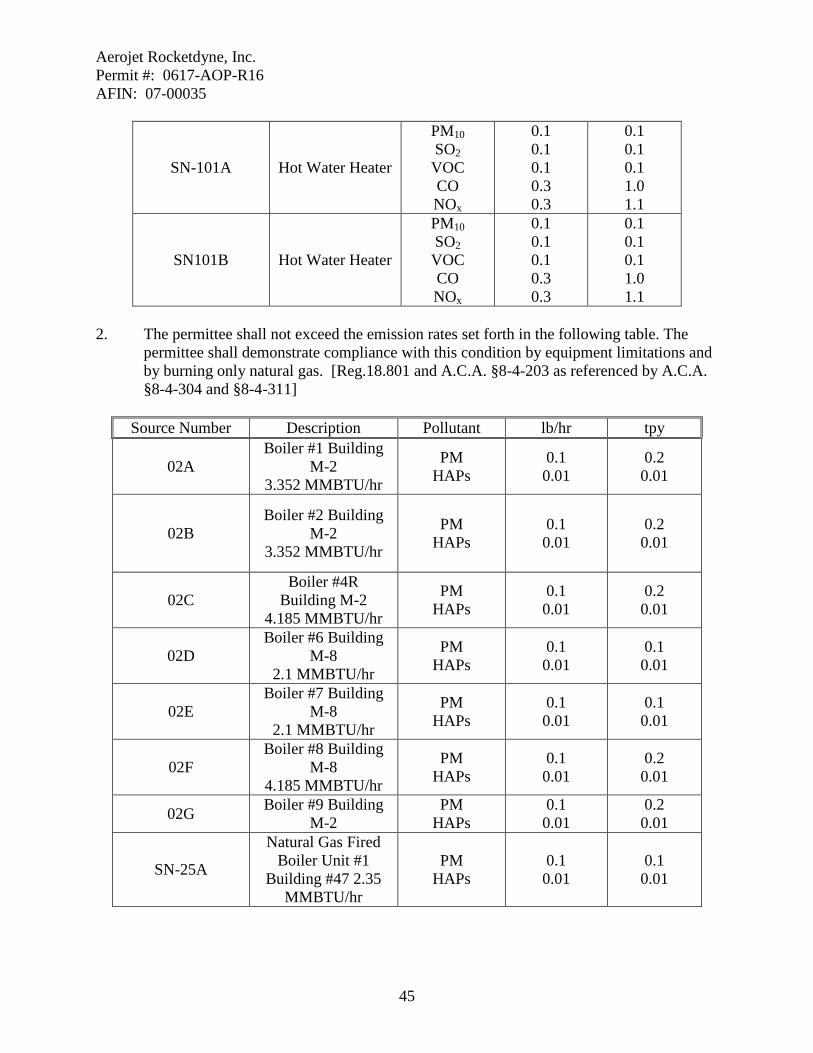
45
SN-101A Hot Water Heater
PM10 SO2 VOC CO NOx
0.1 0.1 0.1 0.3 0.3
0.1 0.1 0.1 1.0 1.1
SN101B Hot Water Heater
PM10 SO2 VOC CO NOx
0.1 0.1 0.1 0.3 0.3
0.1 0.1 0.1 1.0 1.1
2. The permittee shall not exceed the emission rates set forth in the following table. The
permittee shall demonstrate compliance with this condition by equipment limitations and by burning only natural gas. [Reg.18.801 and A.C.A. §8-4-203 as referenced by A.C.A. §8-4-304 and §8-4-311]
Source Number Description Pollutant lb/hr tpy
02A Boiler #1 Building
M-2 3.352 MMBTU/hr
PM HAPs
0.1 0.01
0.2 0.01
02B Boiler #2 Building
M-2 3.352 MMBTU/hr
PM HAPs
0.1 0.01
0.2 0.01
02C Boiler #4R
Building M-2 4.185 MMBTU/hr
PM HAPs
0.1 0.01
0.2 0.01
02D Boiler #6 Building
M-8 2.1 MMBTU/hr
PM HAPs
0.1 0.01
0.1 0.01
02E Boiler #7 Building
M-8 2.1 MMBTU/hr
PM HAPs
0.1 0.01
0.1 0.01
02F Boiler #8 Building
M-8 4.185 MMBTU/hr
PM HAPs
0.1 0.01
0.2 0.01
02G Boiler #9 Building M-2
PM HAPs
0.1 0.01
0.2 0.01
SN-25A
Natural Gas Fired Boiler Unit #1
Building #47 2.35 MMBTU/hr
PM HAPs
0.1 0.01
0.1 0.01

Aerojet Rocketdyne, Inc. Permit #: 0617-AOP-R16 AFIN: 07-00035
46
SN-25C
Natural Gas Fired Boiler Unit #3
Building #48 2.0 MMBTU/hr
PM HAPs
0.1 0.01
0.1 0.01
SN-25E
Natural Gas Fired Boiler Unit #5
Building M-85 2.0 MMBTU/hr
PM HAPs
0.1 0.01
0.1 0.01
SN-25F
Natural Gas Fired Boiler Unit #6
Building M-85 2.0 MMBTU/hr
PM HAPs
0.1 0.01
0.1 0.01
SN-69C Building M-125 2.0 MMBTU/hr
PM HAPs
0.1 0.01
0.1 0.01
SN-69D Building M-125 2.1 MMBTU/hr
PM HAPs
0.1 0.01
0.1 0.01
SN-69E Building 2-SH-2 2.0 MMBTU/hr
PM HAPs
0.1 0.01
0.1 0.01
SN-69F Building 2-SH-2 2.0 MMBTU/hr
PM HAPs
0.1 0.01
0.1 0.01
SN-69G Building 2-SH-2 2.0 MMBTU/hr
PM HAPs
0.1 0.01
0.1 0.01
SN-69H Building 2-SH-2 2.0 MMBTU/hr
PM HAPs
0.1 0.01
0.1 0.01
94 Drying Oven Building M-2
PM HAPs
0.1 0.01
0.1 0.01
96 Boiler Building M-
125 4.185 MMBTU/hr
PM HAPs
0.1 0.1
0.2 0.1
97 Boiler Building M-8 4.185 MMBTU/hr
PM HAPs
0.1 0.1
0.2 0.1
SN-101A Hot Water Heater PM HAPs
0.1 0.01
0.1 0.02
SN101B Hot Water Heater PM HAPs
0.1 0.01
0.1 0.02
3. Visible emissions may not exceed the limits specified in the following table of this permit
as measured by EPA Reference Method 9. Compliance will be demonstrated by only burning natural gas.

Aerojet Rocketdyne, Inc. Permit #: 0617-AOP-R16 AFIN: 07-00035
47
SN Limit Regulatory Citation
02A, 02B, 02D, 02E, 02F, 02G, 25A, 25C, 25E, 25F, 69C, 69D, 69E, 69F, 69G, 69H, 94, 96, 97, 101A, 101B
5% Reg.18.501 and A.C.A. §8-4-203 as referenced by A.C.A. §8-4-304 and
§8-4-311
4. These sources, SN-02A, 02B, 02C, 02D, 02E, 02F, 02G, 25A, 25C, 25E, 25F, 69C, 69D,
69E, 69F, 69G, 69H, and SN-94, are subject to 40 C.F.R Part 63 Subpart DDDDD. SN-02G, SN-96, and 97 are new sources under the MACT and are required to comply upon startup. All other sources are required to comply with this subpart by January 31, 2016. [Reg.19.304 and 40 C.F.R 63, Subpart DDDDD]
5. The permittee shall perform a onetime energy assessment for SN-02A, 02B, 02C, 02D, 02E, 02F, 25A, 25C, 25E, 25F, 69C, 69D, 69E, 69F, 69G, 69H, and 94. [Reg.19.304 and 40 C.F.R 63, Subpart DDDDD]
6. The permittee shall for SN-02A, 02B, 02C, 02D, 02E, 02F, 25A, 25C, 25E, 25F, 69C,
69D, 69E, 69F, 69G, 69H, 94, 96, and 97 conduct an initial tune up and a tune up every 5 years. [Reg.19.304 and 40 C.F.R 63, Subpart DDDDD]
7. The permittee shall submit initial notifications for SN-02A, 02B, 02C, 02D, 02E, 02F, 25A, 25C, 25E, 25F, 69C, 69D, 69E, 69F, 69G, 69H, 94 96, and 97 by the date required in Subpart DDDDD. [Reg.19.304 and 40 C.F.R 63, Subpart DDDDD]
8. The permittee shall maintain all records required by 40 C.F.R 63.7555 and 63.7560.
These records shall be kept for five years minimum, on site, and made available to Department personnel upon request. [Reg.19.304 and 40 C.F.R 63, Subpart DDDDD]
9. The permittee shall submit compliance reports every 5 years as required by 40 C.F.R
63.7555. [Reg.19.304 and 40 C.F.R 63, Subpart DDDDD]

Aerojet Rocketdyne, Inc. Permit #: 0617-AOP-R16 AFIN: 07-00035
48
SN-03A, 03B, 03C, 03D, 03E, 03F, 03G - Rocket Test Facility
Source Description In the Rocket Test Area, the facility test fires a certain number of rocket motors, air bag initiators, and other propellant devices as part of its Quality Assurance/Quality Control (QA/AC) Program. The testing sites include Bay 15, Bay 18, Bay 45, Bay 49, Building 16, Building 19, and the production and development Test Bays 1 and 2 at Building M-85. The amount of energetic material tested ranges from less than one pound to 20,000 pounds per event.
Specific Conditions 10. The permittee shall not exceed the emission rates set forth in the following table. The
permittee shall demonstrate compliance with this condition by Specific Conditions 12 and 13, and equipment limitations. [Reg.19.501 et seq. and 40 C.F.R § 52, Subpart E]
Source Number Description Pollutant lb/hr tpy
03A-G Rocket Test Facility
PM10 VOC CO
NOX Lead
-
48.7 2.5 44.5 0.5 1.5
03A Rocket Test Facility Bay 15
PM10 VOC CO
NOX Lead
1,900.0 100.0
1,765.5 16.5 58.8
03B Rocket Test Facility Bay 18
PM10 VOC CO
NOX Lead
1,900.0 100.0
1,765.5 16.5 58.8
03C Rocket Test Facility Bay 45
PM10 VOC CO
NOX Lead
7,600.0 400.0
7,062.0 66.0 58.8
03D Rocket Test Facility Bay 16
PM10 CO
NOX
45.7 14.7 0.1
03E Rocket Test Facility M-85
PM10 CO
NOX
45.7 14.7 0.1

Aerojet Rocketdyne, Inc. Permit #: 0617-AOP-R16 AFIN: 07-00035
49
Source Number Description Pollutant lb/hr tpy
03F Rocket Test Facility M-125
PM10 CO
NOX
45.7 14.7 0.1
SN-03G
Rocket Test Facility Bay 49
PM10 VOC CO NOx Lead
760.0 40.0 706.2 6.6 39.2
11. The permittee shall not exceed the emission rates set forth in the following table. The
permittee shall demonstrate compliance with this condition by Specific Conditions 12 and 13, and equipment limitations. [Reg.18.801 and A.C.A. §8-4-203 as referenced by A.C.A. §8-4-304 and §8-4-311]
Source Number Description Pollutant lb/hr tpy
03A-G Rocket Test Facility
PM Cadmium Chlorine
Chromium Hydrogen Chloride Hydrogen Fluoride
-
48.7 0.01 0.3 0.11 35.1 0.1
03A Rocket Test
Facility Bay 15
PM Cadmium Chlorine
Chromium Hydrogen Chloride Hydrogen Fluoride
1,900.0 0.46 12.0 4.2
1,400.0 4.1
03B Rocket Test
Facility Bay 18
PM Cadmium Chlorine
Chromium Hydrogen Chloride Hydrogen Fluoride
1,900.0 0.46 12.0 4.2
1,400.0 4.1
03C Rocket Test
Facility Bay 45
PM Cadmium Chlorine
Chromium Hydrogen Chloride Hydrogen Fluoride
7,600.0 0.46 48.0 4.2
5,600.0 16.2

Aerojet Rocketdyne, Inc. Permit #: 0617-AOP-R16 AFIN: 07-00035
50
03D Rocket Test
Facility Bay 16
PM Hydrogen Chloride
45.7 1.6
03E Rocket Test
Facility M-85
PM Hydrogen Chloride
45.7 1.6
03F Rocket Test
Facility M-125
PM Hydrogen Chloride
45.7 1.6
03G Rocket Test
Facility Bay 49
PM Cadmium Chlorine
Chromium Hydrogen Chloride Hydrogen Fluoride
760.0 0.31 4.8 2.8
560.0 1.62
12. The permittee shall not burn in any rocket propellant or air bag propellant in excess of the
limits in the table below. [Reg.19.501 et seq. and 40 C.F.R § 52 Subpart E]
Source Rocket Propellant
Rocket Propellant with
Metals
Air Bag Propellant
03A 5,000 lb/hr 3,000 lb/hr - 03B 5,000 lb/hr 3,000 lb/hr - 03C 20,000 lb/hr 3,000 lb/hr - 03D - - 100 lb/hr 03E - - 100 lb/hr 03F - - 100 lb/hr 03G 2,000 lb/hr 2,000 lb/hr
All SN-03A through SN-03G
250,000 lb/consecutive
12 months
150,000 lb/ consecutive 12
months
5,000 lb/ consecutive 12 months
13. The permittee shall maintain records which demonstrate compliance with the throughput
limit set in Specific Condition 12. These records may be used by the Department for enforcement purposes. Hourly rate records shall be updated on a daily basis. The records for the consecutive twelve month limits shall be updated on a monthly basis. Records shall be updated by the fifteenth day of the month following the month of the records. All records shall be kept on site, and shall be provided to the Department in accordance with General Condition 7. [Reg.19.705 and 40 C.F.R § 52 Subpart E]

Aerojet Rocketdyne, Inc. Permit #: 0617-AOP-R16 AFIN: 07-00035
51
SN-04 - Thermal Treatment Facility
Source Description The Thermal Treatment Facility is where the facility destroys various scrap propellants and other waste energetic materials. Reactive wastes generated at the facility are first assembled in a number of marked accumulation points near the point of generation. The wastes are then collected and transported to the Thermal Treatment Facility. The wastes are placed in a thermal treatment device and destroyed by open burning. The Thermal Treatment Facility is a permitted hazardous waste treatment facility.
Specific Conditions 14. The permittee shall not exceed the emission rates set forth in the following table. The
permittee shall demonstrate compliance with this condition by Specific Conditions 16, 17, and equipment limitations. [Reg.19.501 et seq. and 40 C.F.R § 52, Subpart E]
Source Number Description Pollutant lb/hr tpy
SN-04 Thermal
Treatment Facility
PM10 VOC CO NOx Lead
3,874.4 160.0 40.0 236.0 84.0
143.2 9.3 2.4 13.7 4.9
15. The permittee shall not exceed the emission rates set forth in the following table. The
permittee shall demonstrate compliance with this condition by Specific Conditions 16, 17, and equipment limitations. [Reg.18.801 and Ark. Code Ann. § 8-4-203 as referenced by §§ 8-4-304 and 8-4-311]
Source Number Description Pollutant lb/hr tpy
SN-04 Thermal
Treatment Facility
PM Cadmium Chlorine
Chromium, Trivalent Chromium, Hexavalent
Hydrogen Chloride Hydrogen Fluoride
3,874.4 0.97 129.6 7.9 0.13
1840.8 12.0
143.2 0.06 7.5 0.45 0.01 106.5 0.7
16. The permittee shall not burn waste rocket or airbag propellant at SN-04 in excess of
limits in the following table. [Reg.19.501 et seq. and 40 C.F.R § 52 Subpart E]

Aerojet Rocketdyne, Inc. Permit #: 0617-AOP-R16 AFIN: 07-00035
52
Material Hourly Rate Limit Consecutive 12 month limit
Waste Rocket Propellant 8000 pounds per hour 925,000 pounds per year Miscellaneous Energetic
Materials 8000 pounds per hour 25,000 pounds per year
17. The permittee shall maintain records which demonstrate compliance with the throughput
limits set in Specific Condition 16. These records may be used by the Department for enforcement purposes. Hourly rate records shall be updated on a daily basis. The records for the consecutive twelve month limits shall be updated on a monthly basis. Records shall be updated by the fifteenth day of the month following the month of the records. All records shall be kept on site, and shall be provided to the Department in accordance with General Condition 7. [Reg.19.705 and 40 C.F.R § 52 Subpart E]

Aerojet Rocketdyne, Inc. Permit #: 0617-AOP-R16 AFIN: 07-00035
53
SN-07 - Liner Mixer and Spray Liner Machine
Source Description The Liner Mixer and Spray Machine are used to prepare and apply liner materials to the insides of the rocker motor cases. This equipment is located in Building M-8. The motor cases may be either insulated or bare metal. The liner materials are mixed in a closed mixer and then mechanically applied to the interior of the degreased motor case. The batch lining operation is performed one component at a time. Plantwide Condition 7 lists available solvents and VOC/HAP compositions.
Specific Conditions 18. The permittee shall not exceed the emission rates set forth in the following table. The
permittee shall demonstrate compliance with this condition by Plantwide Condition 7 and equipment limitations. [Reg.19.501 et seq. and 40 C.F.R § 52, Subpart E]
Source Number Description Pollutant lb/hr tpy
SN-07 Liner Mixer and Spray Liner Machine VOC 17.0 2.2

Aerojet Rocketdyne, Inc. Permit #: 0617-AOP-R16 AFIN: 07-00035
54
SN-11 - Lacquer Preparation
Source Description Various liquid explosives are called Alacquer@ by the permittee. Lacquer preparation is done in Building C-56. Preparation of liquid explosive compounds involves the use of organic solvents for stabilizing agents. These solvents include: acetone, methylene chloride, ethyl alcohol, and isopropyl alcohol. Lacquer received from outside venders is premixed with any of those solvents before transportation. These solvents are removed from the lacquer before use by nitrogen gas stripping. Lacquer preparation also includes adding solvents to liquid explosives prior to their use, shipment, and/or long-term storage. Plantwide Condition 7 lists available solvents and VOC/HAP compositions.
Specific Conditions 19. The permittee shall not exceed the emission rates set forth in the following table. The
permittee shall demonstrate compliance with this condition by Specific Condition 21, Plantwide Condition 7, and equipment limitations. [Reg.19.501 et seq. and 40 C.F.R § 52, Subpart E]
Source Number Description Pollutant lb/hr tpy
SN-11 Lacquer Preparation VOC 40.1 5.1 20. The permittee shall not exceed the emission rates set forth in the following table. The
permittee shall demonstrate compliance with this condition by Specific Condition 21, Plantwide Condition 7, and equipment limitations. [Reg.18.801 and Ark. Code Ann. § 8-4-203 as referenced by §§ 8-4-304 and 8-4-311]
Source Number Description Pollutant lb/hr tpy
SN-11 Lacquer Preparation Acetone Methylene Chloride
40.1 40.1
5.1 5.1
21. The permittee shall not use in excess of 20,000 pounds of lacquer premix in SN-11
during any consecutive twelve month period. [Reg.19.501 et seq. and 40 C.F.R § 52 Subpart E]
22. The permittee shall maintain records which demonstrate compliance with the throughput
limit set in Specific Condition 21. These records may be used by the Department for enforcement purposes. Records shall be updated on a monthly basis, shall be kept on site, and shall be provided to the Department in accordance with General Condition 7. Records shall be updated by the fifteenth day of the month following the month of the records. [Reg.19.705 and 40 C.F.R § 52 Subpart E]

Aerojet Rocketdyne, Inc. Permit #: 0617-AOP-R16 AFIN: 07-00035
55
SN-12 - Spray Paint Booth
Source Description This spray painting area is located at Building C-60. Only a limited amount of surface coating is performed at this location. The paints are applied using aerosol spray cans. The painting area is equipped with a vent hood for general ventilation. In addition to painting, solvents are used to clean various components prior to further processing. The cleaning agents are applied with wiping cloths. Alternative solvents are also be used. Plantwide Condition 7 lists available solvents and VOC/HAP compositions and Plantwide Condition 11 lists available paint VOC/HAP compositions. Plantwide Condition 19 lists available adhesive VOC/HAP compositions.
Specific Conditions 23. The permittee shall not exceed the emission rates set forth in the following table. The
permittee shall demonstrate compliance with this condition by Plantwide Conditions 7, 9, 11, and equipment limitations. [Reg.19.501 et seq. and 40 C.F.R § 52, Subpart E]
Source Number Description Pollutant lb/hr tpy
SN-12 Spray Paint Booth PM10 VOC Lead
0.1 15.5 0.01
0.1 2.6 0.01
24. The permittee shall not exceed the emission rates set forth in the following table. The
permittee shall demonstrate compliance with this condition by Plantwide Conditions 7, 9, 11, 17, and 19 and equipment limitations. [Reg.18.801 and Ark. Code Ann. § 8-4-203 as referenced by §§ 8-4-304 and 8-4-311]
Source Number Description Pollutant lb/hr tpy
SN-12 Spray Paint Booth
PM Acetone Cumene
Ethyl Acrylate Ethyl Benzene
Methanol Methyl Isobutyl Ketone
Toluene Xylene
0.1 9.4 0.4 1.1 0.7 1.4 4.2 6.0 4.2
0.1 1.4 0.1 0.3 0.2 0.4 1.1 1.5 1.1

Aerojet Rocketdyne, Inc. Permit #: 0617-AOP-R16 AFIN: 07-00035
56
SN-13 - Ultrasonic Cleaner
Source Description The Ultrasonic Cleaner is used to clean/degrease a variety of small parts. The cleaner consists of a one-liter beaker set in an ultrasonic waterbath. This open-top, batch vapor degreaser has a surface area of 1.95 square feet. It is located in Building M-85. Plantwide Condition 7 lists available solvents and VOC/HAP compositions. This source is not subject to 40 C.F.R 63, Subpart T because a halogenated solvent as defined by Subpart T is not used in this equipment.
Specific Conditions 25. The permittee shall not exceed the emission rates set forth in the following table. The
permittee shall demonstrate compliance with this condition by Plantwide Condition 7 and equipment limitations. [Reg.19.501 et seq. and 40 C.F.R § 52, Subpart E]
Source Number Description Pollutant lb/hr tpy
SN-13 Ultrasonic Cleaner VOC 0.2 0.3 26. The permittee shall not exceed the emission rates set forth in the following table. The
permittee shall demonstrate compliance with this condition by Plantwide Condition 7 and equipment limitations. [Reg.18.801 and Regulation 18 and Ark. Code Ann. § 8-4-203 as referenced by §§ 8-4-304 and 8-4-311]
Source Number Description Pollutant lb/hr tpy
SN-13 Ultrasonic Cleaner 1,2-Butylene Oxide 0.01 0.01 27. The permittee shall not use any halogenated solvents as defined by MACT Subpart T at
this source. [Ark. Code Ann. § 8-4-203 as referenced by §§ 8-4-304 and 8-4-311]

Aerojet Rocketdyne, Inc. Permit #: 0617-AOP-R16 AFIN: 07-00035
57
SN-19 - Motor Case Cleaner
Source Description This Motor Case Cleaner is used to clean/degrease rocket motor cases prior to further processing. This source is located in Building 2-SH-14 and has a capacity of 1,200 gallons of solvent. It is an open-top, batch degreaser with a working area of 44.0 square feet. Various solvents will be used in the degreaser. Plantwide Condition 7 lists available solvents and VOC/HAP compositions. This source is not subject to 40 C.F.R 63, Subpart T because a halogenated solvent as defined by Subpart T is not used in this equipment.
Specific Conditions 28. The permittee shall not exceed the emission rates set forth in the following table. The
permittee shall demonstrate compliance with this condition by Plantwide Condition 7 and equipment limitations. [Reg.19.501 et seq. and 40 C.F.R § 52, Subpart E]
Source Number Description Pollutant lb/hr tpy
SN-19 Motor Case Cleaner VOC 6.6 13.8 29. The permittee shall not exceed the emission rates set forth in the following table. The
permittee shall demonstrate compliance with this condition by Plantwide Condition 7 and equipment limitations. [Reg.18.801 and Ark. Code Ann. § 8-4-203 as referenced by §§ 8-4-304 and 8-4-311]
Source Number Description Pollutant lb/hr tpy
SN-19 Motor Case Cleaner 1,2-Butylene Oxide 0.07 0.14 30. The permittee shall not use any halogenated solvents as defined by MACT Subpart T at
this source. [Ark. Code Ann. § 8-4-203 as referenced by §§ 8-4-304 and 8-4-311]

Aerojet Rocketdyne, Inc. Permit #: 0617-AOP-R16 AFIN: 07-00035
58
SN-20A and B - Solvent Wipe Rooms
Source Description One wipe room is operated in Building 2-SH-14, SN-20A, and one wipe room is operated in Building 2-SH-15, SN-20B. These rooms are used for motor case degreasing prior to application of the case liner. Other parts cleaning activities are also done. The solvents are manually applied using wiping cloths, and the components are allowed to air-dry. Plantwide Condition 7 lists available solvents and VOC/HAP compositions. This source is not subject to 40 C.F.R 63, Subpart T because it is a hand-wipe cleaning activity.
Specific Conditions 31. The permittee shall not exceed the emission rates set forth in the following table. The
permittee shall demonstrate compliance with this condition by Plantwide Condition 7 and equipment limitations. [Reg.19.501 et seq. and 40 C.F.R § 52, Subpart E]
Source Description Pollutant lb/hr tpy
SN-20A Solvent Wipe Rooms VOC 8.5 2.2 SN-20B Solvent Wipe Rooms VOC 8.5

Aerojet Rocketdyne, Inc. Permit #: 0617-AOP-R16 AFIN: 07-00035
59
SN-22 - Mix Room
Source Description This mix room, located in Building 2-SH-15, is used to mix ingredients during the preparation of motor case liner materials. Plantwide Condition 7 lists available solvents and VOC/HAP compositions.
Specific Conditions 32. The permittee shall not exceed the emission rates set forth in the following table. The
permittee shall demonstrate compliance with this condition by Plantwide Condition 7 and equipment limitations. [Reg.19.501 et seq. and 40 C.F.R § 52, Subpart E]
Source Description Pollutant lb/hr tpy
SN-22 Mix Room VOC 8.5 4.3
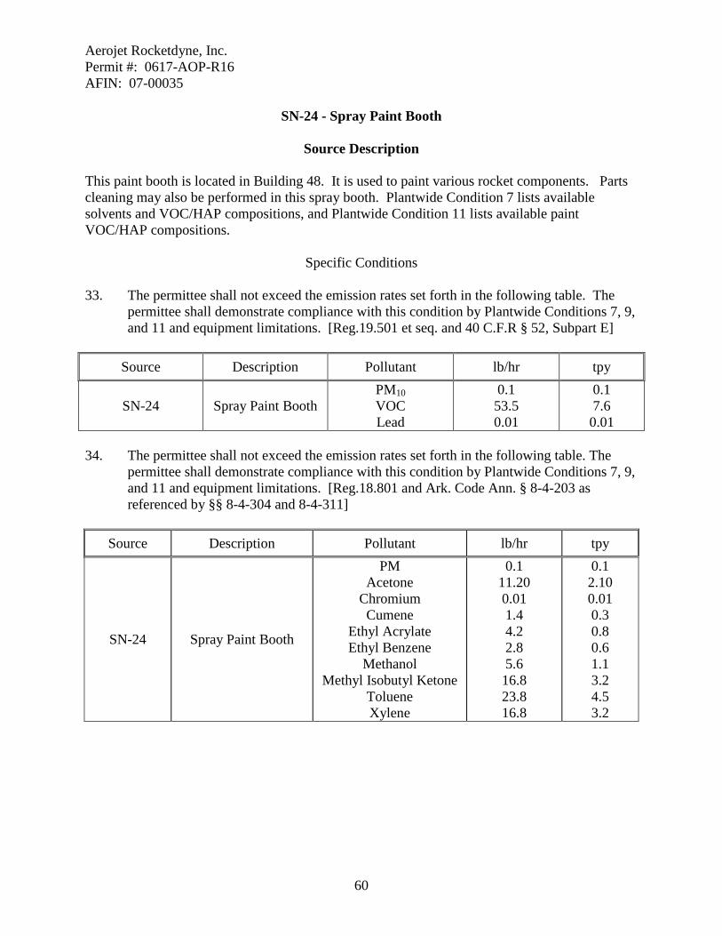
Aerojet Rocketdyne, Inc. Permit #: 0617-AOP-R16 AFIN: 07-00035
60
SN-24 - Spray Paint Booth
Source Description This paint booth is located in Building 48. It is used to paint various rocket components. Parts cleaning may also be performed in this spray booth. Plantwide Condition 7 lists available solvents and VOC/HAP compositions, and Plantwide Condition 11 lists available paint VOC/HAP compositions.
Specific Conditions 33. The permittee shall not exceed the emission rates set forth in the following table. The
permittee shall demonstrate compliance with this condition by Plantwide Conditions 7, 9, and 11 and equipment limitations. [Reg.19.501 et seq. and 40 C.F.R § 52, Subpart E]
Source Description Pollutant lb/hr tpy
SN-24 Spray Paint Booth PM10 VOC Lead
0.1 53.5 0.01
0.1 7.6 0.01
34. The permittee shall not exceed the emission rates set forth in the following table. The
permittee shall demonstrate compliance with this condition by Plantwide Conditions 7, 9, and 11 and equipment limitations. [Reg.18.801 and Ark. Code Ann. § 8-4-203 as referenced by §§ 8-4-304 and 8-4-311]
Source Description Pollutant lb/hr tpy
SN-24 Spray Paint Booth
PM Acetone
Chromium Cumene
Ethyl Acrylate Ethyl Benzene
Methanol Methyl Isobutyl Ketone
Toluene Xylene
0.1 11.20 0.01 1.4 4.2 2.8 5.6 16.8 23.8 16.8
0.1 2.10 0.01 0.3 0.8 0.6 1.1 3.2 4.5 3.2

Aerojet Rocketdyne, Inc. Permit #: 0617-AOP-R16 AFIN: 07-00035
61
SN-28 - Spray Liner Machine and Mixer Unit
Source Description The Liner Spray Machine is used to apply a liner material to the insides of the rocker motor cases. This equipment is located in Building M-2. The motor cases may be either insulated or bare metal. The liner material is mechanically applied to the interior of the degreased motor case. Plantwide Condition 7 lists available solvents and VOC/HAP compositions.
Specific Conditions 35. The permittee shall not exceed the emission rates set forth in the following table. The
permittee shall demonstrate compliance with this condition by Plantwide Condition 7 and equipment limitations. [Reg.19.501 et seq. and 40 C.F.R § 52, Subpart E]
Source Description Pollutant lb/hr tpy
SN-28 Spray Liner Machine and Mixer Unit VOC 17.0 2.2

Aerojet Rocketdyne, Inc. Permit #: 0617-AOP-R16 AFIN: 07-00035
62
SN-30 - High Explosives Test Facility
Source Description The facility conducts performance-testing of energetic materials at the High Explosive Test Facility as part of its QA/QC Program. This facility is located in the 16-AT Area of the Highland Industrial Park approximately nine miles from the main complex. The explosives are detonated with initiation by impact of a bullet, by falling, or by a cap-initiated high-explosive donor charge. Testing is also initiated by controlled bonfire and under proof-of-fire conditions. Test items range from finished components to military ordnance to R&D test samples.
Specific Conditions 36. The permittee shall not exceed the emission rates set forth in the following table. The
permittee shall demonstrate compliance with this condition by Specific Conditions 38 and 40 and equipment limitations. [Reg.19.501 et seq. and 40 C.F.R § 52, Subpart E]
Source Description Pollutant lb/hr tpy
SN-30 High Explosives Test Facility
PM10 VOC CO NOx Lead
137.0 6.0
106.0 1.0 5.88
5.5 0.3 4.3 0.1 0.24
37. The permittee shall not exceed the emission rates set forth in the following table. The
permittee shall demonstrate compliance with this condition by Specific Conditions 38 and 40, and equipment limitations. [Reg.18.801 and Ark. Code Ann. § 8-4-203 as referenced by §§ 8-4-304 and 8-4-311]
Source Description Pollutant lb/hr Tpy
SN-30 High Explosives Test Facility
PM Cadmium Chlorine
Chromium, Trivalent Hydrogen Chloride
137.0 0.05 0.72 0.42 89.1
5.5 0.01 0.03 0.02 3.8
38. The permittee shall not use in excess of 300 pounds of energetic materials in SN-30
during any one hour period. [Reg.19.501 et seq. and 40 C.F.R § 52 Subpart E] 39. The permittee shall maintain records which demonstrate compliance with the throughput
limit set in Specific Condition 38. These records may be used by the Department for enforcement purposes. Records shall be updated on a monthly basis, shall be kept on site, and shall be provided to Department as required in General Provision 7. Records

Aerojet Rocketdyne, Inc. Permit #: 0617-AOP-R16 AFIN: 07-00035
63
shall be updated by the fifteenth day of the month following the month of the records. [Reg.19.705 and 40 C.F.R § 52 Subpart E]
40. The permittee shall not use in excess of 24,000 pounds of energetic materials in SN-30
during any consecutive 12 month period. [Reg.19.501 et seq. and 40 C.F.R § 52 Subpart E]
41. The permittee shall maintain records which demonstrate compliance with the throughput
limit set in Specific Condition 40. These records may be used by the Department for enforcement purposes. Records shall be updated on a monthly basis, shall be kept on site, and shall be provided to Department as required in General Provision 7. Records shall be updated by the fifteenth day of the month following the month of the records. [Reg.19.705 and 40 C.F.R § 52 Subpart E]
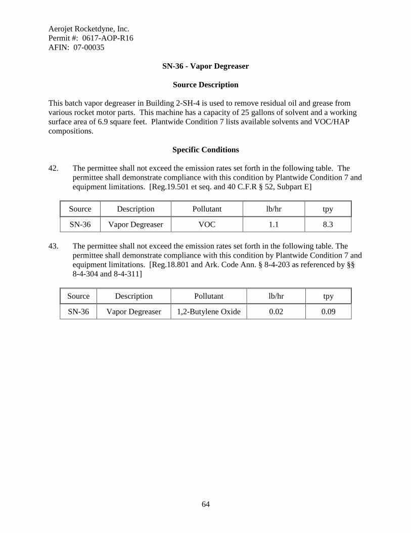
Aerojet Rocketdyne, Inc. Permit #: 0617-AOP-R16 AFIN: 07-00035
64
SN-36 - Vapor Degreaser
Source Description This batch vapor degreaser in Building 2-SH-4 is used to remove residual oil and grease from various rocket motor parts. This machine has a capacity of 25 gallons of solvent and a working surface area of 6.9 square feet. Plantwide Condition 7 lists available solvents and VOC/HAP compositions.
Specific Conditions 42. The permittee shall not exceed the emission rates set forth in the following table. The
permittee shall demonstrate compliance with this condition by Plantwide Condition 7 and equipment limitations. [Reg.19.501 et seq. and 40 C.F.R § 52, Subpart E]
Source Description Pollutant lb/hr tpy
SN-36 Vapor Degreaser VOC 1.1 8.3 43. The permittee shall not exceed the emission rates set forth in the following table. The
permittee shall demonstrate compliance with this condition by Plantwide Condition 7 and equipment limitations. [Reg.18.801 and Ark. Code Ann. § 8-4-203 as referenced by §§ 8-4-304 and 8-4-311]
Source Description Pollutant lb/hr tpy
SN-36 Vapor Degreaser 1,2-Butylene Oxide 0.02 0.09

Aerojet Rocketdyne, Inc. Permit #: 0617-AOP-R16 AFIN: 07-00035
65
SN-37A and B - Motor Case Cleaning (Prior to Grit Blasting)
Source Description This operation, located in Building 2-SH-2, SN-37A, or Building 2-SH-14, SN-37B, consists of removing residual preservative oil from rocket motor cases. Plantwide Condition 7 lists available solvents and VOC/HAP compositions. This source is not subject to 40 C.F.R 63, Subpart T because these provisions do not regulate the use of halogenated solvents in hand-wipe cleaning activities.
Specific Conditions 44. The permittee shall not exceed the emission rates set forth in the following table. The
permittee shall demonstrate compliance with this condition by Plantwide Condition 7 and equipment limitations. [Reg.19.501 et seq. and 40 C.F.R § 52, Subpart E]
Source Description Pollutant lb/hr tpy
SN-37A Motor Case Cleaning (Prior to Grit Blasting)
VOC 4.3 1.5
SN-37B VOC 4.3

Aerojet Rocketdyne, Inc. Permit #: 0617-AOP-R16 AFIN: 07-00035
66
SN-38A and B - Motor Case Cleaning (After Grit Blasting)
Source Description This operation, located in Building 2-SH-2, SN-38A, or Building 2-SH-14, SN-38B consists of removing dust from rocket motor cases after they have been grit blasted. This source is not subject to 40 C.F.R 63 Subpart T because these provisions do not regulate the use of halogenated solvents in hand-wipe cleaning activities.
Specific Conditions 45. The permittee shall not exceed the emission rates set forth in the following table. The
permittee shall demonstrate compliance with this condition by Plantwide Condition 7 and equipment limitations. [Reg.19.501 et seq. and 40 C.F.R § 52, Subpart E]
Source Description Pollutant lb/hr tpy
SN-38A Motor Case Cleaning (After to Grit Blasting)
VOC 4.3 1.5
SN-38B VOC 4.3

Aerojet Rocketdyne, Inc. Permit #: 0617-AOP-R16 AFIN: 07-00035
67
SN-39A and B - Adhesive Primer Operations
Source Description Adhesive Primer Operations are located in Building 2-SH-14, SN-39A, and 2-SH-15, SN-39B. Interior surfaces of clean, dry rocket motor cases are coated with an adhesive primer. Thinning of the primer is done using methyl ethyl ketone. The primer is applied by hand.
Specific Conditions 46. The permittee shall not exceed the emission rates set forth in the following table. The
permittee shall demonstrate compliance with this condition by Plantwide Conditions 7, 17, and 19and equipment limitations. [Reg.19.501 et seq. and 40 C.F.R § 52, Subpart E] Source Description Pollutant lb/hr tpy
SN-39A Adhesive Primer Operations VOC 10.0
3.0 SN-39B Adhesive Primer
Operations VOC 10.0
47. The permittee shall not exceed the emission rates set forth in the following table. The
permittee shall demonstrate compliance with this condition by Plantwide Conditions 7, 17, and 19 and equipment limitations. [Reg.18.801 and Ark. Code Ann. § 8-4-203 as referenced by §§ 8-4-304 and 8-4-311]
Pollutant Description Pollutant lb/hr tpy
SN-39A Adhesive Primer Operations
1,2-Butylene Oxide Ethyl Benzene Formaldehyde
Methanol Methyl Isobutyl Ketone
Tetrachloroethylene Toluene
1,1,1-Trichloroethane Trichloroethylene
Xylene
0.29 1.44 0.03 1.2 3.8 0.9 1.5 3.2 2.3 4.9
0.12 0.58 0.02 0.46 1.5 0.35 0.58 1.27 0.92 1.96
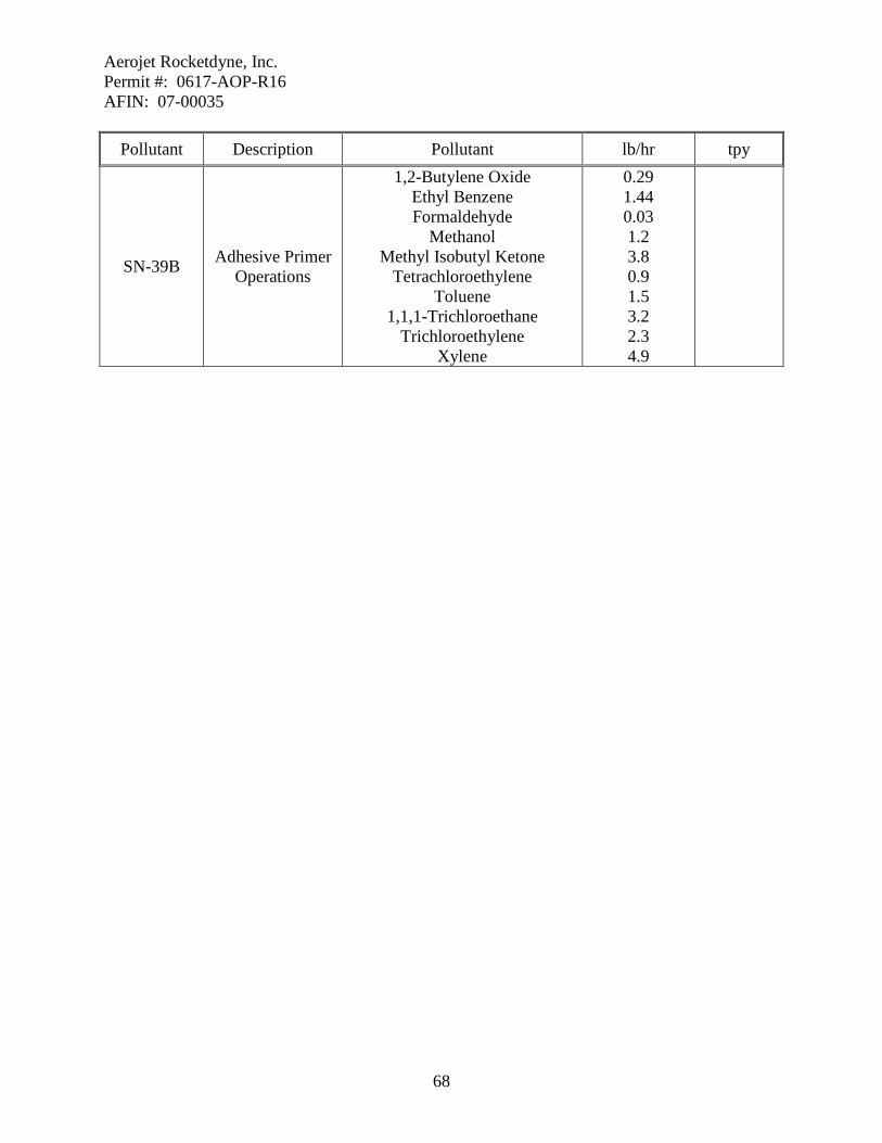
Aerojet Rocketdyne, Inc. Permit #: 0617-AOP-R16 AFIN: 07-00035
68
Pollutant Description Pollutant lb/hr tpy
SN-39B Adhesive Primer Operations
1,2-Butylene Oxide Ethyl Benzene Formaldehyde
Methanol Methyl Isobutyl Ketone
Tetrachloroethylene Toluene
1,1,1-Trichloroethane Trichloroethylene
Xylene
0.29 1.44 0.03 1.2 3.8 0.9 1.5 3.2 2.3 4.9
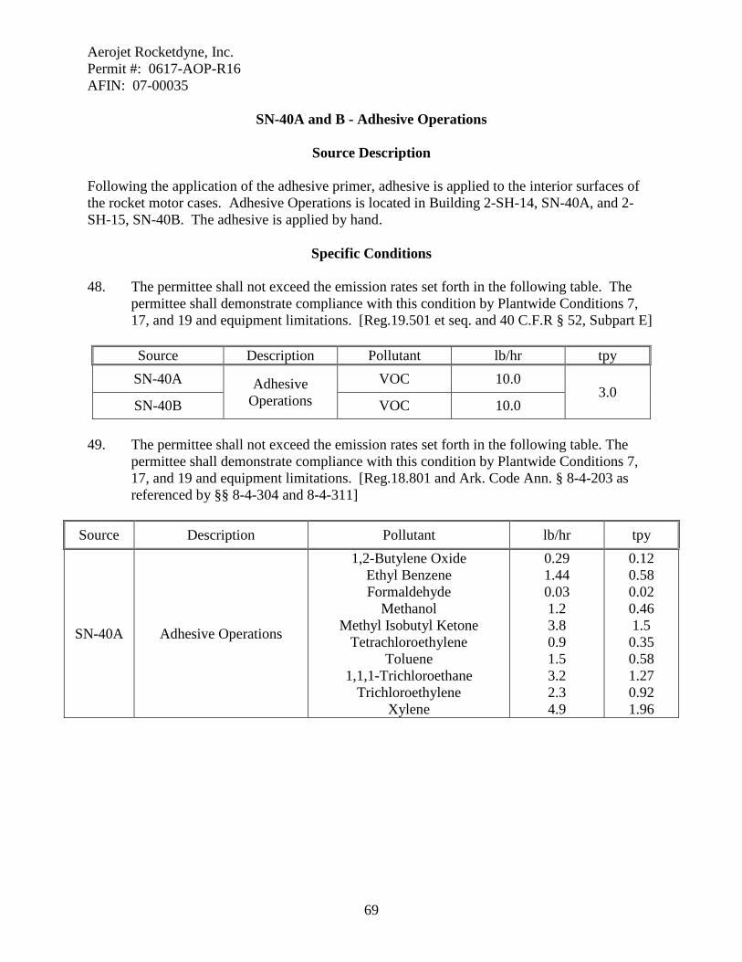
Aerojet Rocketdyne, Inc. Permit #: 0617-AOP-R16 AFIN: 07-00035
69
SN-40A and B - Adhesive Operations
Source Description Following the application of the adhesive primer, adhesive is applied to the interior surfaces of the rocket motor cases. Adhesive Operations is located in Building 2-SH-14, SN-40A, and 2-SH-15, SN-40B. The adhesive is applied by hand.
Specific Conditions 48. The permittee shall not exceed the emission rates set forth in the following table. The
permittee shall demonstrate compliance with this condition by Plantwide Conditions 7, 17, and 19 and equipment limitations. [Reg.19.501 et seq. and 40 C.F.R § 52, Subpart E] Source Description Pollutant lb/hr tpy
SN-40A Adhesive Operations
VOC 10.0 3.0
SN-40B VOC 10.0
49. The permittee shall not exceed the emission rates set forth in the following table. The permittee shall demonstrate compliance with this condition by Plantwide Conditions 7, 17, and 19 and equipment limitations. [Reg.18.801 and Ark. Code Ann. § 8-4-203 as referenced by §§ 8-4-304 and 8-4-311]
Source Description Pollutant lb/hr tpy
SN-40A Adhesive Operations
1,2-Butylene Oxide Ethyl Benzene Formaldehyde
Methanol Methyl Isobutyl Ketone
Tetrachloroethylene Toluene
1,1,1-Trichloroethane Trichloroethylene
Xylene
0.29 1.44 0.03 1.2 3.8 0.9 1.5 3.2 2.3 4.9
0.12 0.58 0.02 0.46 1.5 0.35 0.58 1.27 0.92 1.96

Aerojet Rocketdyne, Inc. Permit #: 0617-AOP-R16 AFIN: 07-00035
70
Source Description Pollutant lb/hr tpy
SN-40B Adhesive Operations
1,2-Butylene Oxide Ethyl Benzene Formaldehyde
Methanol Methyl Isobutyl Ketone
Tetrachloroethylene Toluene
1,1,1-Trichloroethane Trichloroethylene
Xylene
0.29 1.44 0.03 1.2 3.8 0.9 1.5 3.2 2.3 4.9

Aerojet Rocketdyne, Inc. Permit #: 0617-AOP-R16 AFIN: 07-00035
71
SN-41A and 41B - Adhesive Barrier Coating Operations
Source Description Following the adhesive application, an adhesive barrier coating is applied to the interior surfaces of the rocket motor cases. This operation is performed in Building 2-SH-14, SN-41A, and Building S-SH-15, SN-41B. The barrier coating is applied by spray nozzles mounted on an automated, traveling wand.
Specific Conditions 50. The permittee shall not exceed the emission rates set forth in the following table. The
permittee shall demonstrate compliance with this condition by Plantwide Conditions 7, 17, and 19 and equipment limitations. [Reg.19.501 et seq. and 40 C.F.R § 52, Subpart E] Source Description Pollutant lb/hr tpy
SN-41A Adhesive Barrier Coating Operations
VOC 10.0 3.0 SN-41B VOC 10.0
51. The permittee shall not exceed the emission rates set forth in the following table. The permittee shall demonstrate compliance with this condition by Plantwide Conditions 7, 17, and 19 and equipment limitations. [Reg.18.801 and Ark. Code Ann. § 8-4-203 as referenced by §§ 8-4-304 and 8-4-311]
Source Description Pollutant lb/hr tpy
SN-41A Adhesive Barrier Coating Operations
1,2-Butylene Oxide Ethyl Benzene Formaldehyde
Methanol Methyl Isobutyl Ketone
Tetrachloroethylene Toluene
1,1,1-Trichloroethane Trichloroethylene
Xylene
0.29 1.44 0.03 1.2 3.8 0.9 1.5 3.2 2.3 4.9
0.12 0.58 0.02 0.46 1.5 0.35 0.58 1.27 0.92 1.96

Aerojet Rocketdyne, Inc. Permit #: 0617-AOP-R16 AFIN: 07-00035
72
Source Description Pollutant lb/hr tpy
SN-41B Adhesive Barrier Coating Operations
1,2-Butylene Oxide Ethyl Benzene Formaldehyde
Methanol Methyl Isobutyl Ketone
Tetrachloroethylene Toluene
1,1,1-Trichloroethane Trichloroethylene
Xylene
0.29 1.44 0.03 1.2 3.8 0.9 1.5 3.2 2.3 4.9

Aerojet Rocketdyne, Inc. Permit #: 0617-AOP-R16 AFIN: 07-00035
73
SN-42 - Spray Liner Machine
Source Description In Building 2-SH-15, a liner material is mechanically applied to the adhesive surface of rocket motor casings. Various solvents are used to flush the equipment.
Specific Conditions 52. The permittee shall not exceed the emission rates set forth in the following table. The
permittee shall demonstrate compliance with this condition by Plantwide Condition 7 and equipment limitations. [Reg.19.501 et seq. and 40 C.F.R § 52, Subpart E]
Source Description Source Description tpy
SN-42 Spray Liner Machine VOC 8.5 1.1

Aerojet Rocketdyne, Inc. Permit #: 0617-AOP-R16 AFIN: 07-00035
74
SN-43 - Spray Paint Booth
Source Description This paint booth is located in Building D-33. This booth is used to surface coat various rocket components.
Specific Conditions 53. The permittee shall not exceed the emission rates set forth in the following table. The
permittee shall demonstrate compliance with this condition by Plantwide Conditions 7, 9, and 11 and equipment limitations. [Reg.19.501 et seq. and 40 C.F.R § 52, Subpart E]
Source Description Pollutant lb/hr tpy
SN-43 Spray Paint Booth PM10 VOC Lead
0.1 22.5 0.01
0.1 8.5 0.01
54. The permittee shall not exceed the emission rates set forth in the following table. The
permittee shall demonstrate compliance with this condition by Plantwide Conditions 7, 9, and 11 and equipment limitations. [Reg.18.801 and Ark. Code Ann. § 8-4-203 as referenced by §§ 8-4-304 and 8-4-311]
Source Description Pollutant lb/hr tpy
SN-43 Spray Paint Booth
PM Acetone
Chromium Cumene
Ethyl Acrylate Ethyl Benzene
Methanol Methyl Isobutyl Ketone
Toluene Xylene
0.1 5.6 0.01 0.7 2.1 1.4 2.8 8.4 11.9 8.4
0.1 2.8 0.01 0.4 1.1 0.7 1.4 4.2 6.0 4.2

Aerojet Rocketdyne, Inc. Permit #: 0617-AOP-R16 AFIN: 07-00035
75
SN-44A, 44B, 44C, 44D - Floor Operations
Source Description These sources consist of various touch-up painting, bonding, labeling, and cleaning activities located throughout the facility. SN-44A is in Building #33, SN-44B is in Building #48, SN-44C is in Building M-2, and SN-44D is in Building M-85. All of these activities are done by hand. This source is not subject to 40 C.F.R 63, Subpart T because these provisions do not regulate the use of halogenated solvents in hand-wipe cleaning activities.
Specific Conditions 55. The permittee shall not exceed the emission rates set forth in the following table. The
permittee shall demonstrate compliance with this condition by Plantwide Conditions 7, 9, 11, 13, 15, 17, and 19 and equipment limitations. [Reg.19.501 et seq. and 40 C.F.R § 52, Subpart E] Source Description Pollutant lb/hr tpy
SN-44A
Floor Operations
PM10 VOC Lead
0.1 30.3 0.01
0.1 39.3 0.01
SN-44B PM10 VOC Lead
0.1 30.3 0.01
SN-44C PM10 VOC Lead
0.1 30.3 0.01
SN-44D PM10 VOC Lead
0.1 30.3 0.01
56. The permittee shall not exceed the emission rates set forth in the following table. The
permittee shall demonstrate compliance with this condition by Plantwide Conditions 7, 9, 11, 13, 15, 17, and 19 and equipment limitations. [Reg.18.801 and Ark. Code Ann. § 8-4-203 as referenced by §§ 8-4-304 and 8-4-311]
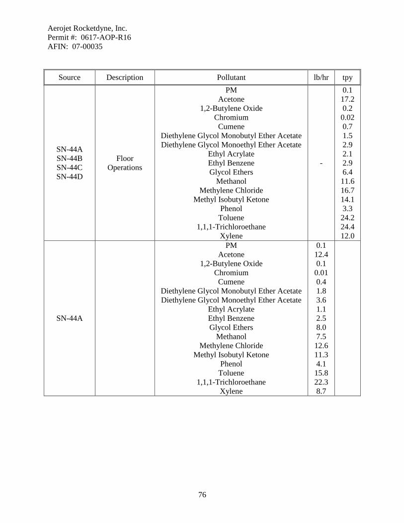
Aerojet Rocketdyne, Inc. Permit #: 0617-AOP-R16 AFIN: 07-00035
76
Source Description Pollutant lb/hr tpy
SN-44A SN-44B SN-44C SN-44D
Floor Operations
PM Acetone
1,2-Butylene Oxide Chromium Cumene
Diethylene Glycol Monobutyl Ether Acetate Diethylene Glycol Monoethyl Ether Acetate
Ethyl Acrylate Ethyl Benzene Glycol Ethers
Methanol Methylene Chloride
Methyl Isobutyl Ketone Phenol Toluene
1,1,1-Trichloroethane Xylene
-
0.1 17.2 0.2 0.02 0.7 1.5 2.9 2.1 2.9 6.4 11.6 16.7 14.1 3.3 24.2 24.4 12.0
SN-44A
PM Acetone
1,2-Butylene Oxide Chromium Cumene
Diethylene Glycol Monobutyl Ether Acetate Diethylene Glycol Monoethyl Ether Acetate
Ethyl Acrylate Ethyl Benzene Glycol Ethers
Methanol Methylene Chloride
Methyl Isobutyl Ketone Phenol Toluene
1,1,1-Trichloroethane Xylene
0.1 12.4 0.1 0.01 0.4 1.8 3.6 1.1 2.5 8.0 7.5 12.6 11.3 4.1 15.8 22.3 8.7
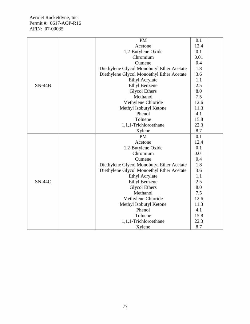
Aerojet Rocketdyne, Inc. Permit #: 0617-AOP-R16 AFIN: 07-00035
77
SN-44B
PM Acetone
1,2-Butylene Oxide Chromium Cumene
Diethylene Glycol Monobutyl Ether Acetate Diethylene Glycol Monoethyl Ether Acetate
Ethyl Acrylate Ethyl Benzene Glycol Ethers
Methanol Methylene Chloride
Methyl Isobutyl Ketone Phenol Toluene
1,1,1-Trichloroethane Xylene
0.1 12.4 0.1 0.01 0.4 1.8 3.6 1.1 2.5 8.0 7.5 12.6 11.3 4.1 15.8 22.3 8.7
SN-44C
PM Acetone
1,2-Butylene Oxide Chromium Cumene
Diethylene Glycol Monobutyl Ether Acetate Diethylene Glycol Monoethyl Ether Acetate
Ethyl Acrylate Ethyl Benzene Glycol Ethers
Methanol Methylene Chloride
Methyl Isobutyl Ketone Phenol Toluene
1,1,1-Trichloroethane Xylene
0.1 12.4 0.1 0.01 0.4 1.8 3.6 1.1 2.5 8.0 7.5 12.6 11.3 4.1 15.8 22.3 8.7

Aerojet Rocketdyne, Inc. Permit #: 0617-AOP-R16 AFIN: 07-00035
78
SN-44D
PM Acetone
1,2-Butylene Oxide Chromium Cumene
Diethylene Glycol Monobutyl Ether Acetate Diethylene Glycol Monoethyl Ether Acetate
Ethyl Acrylate Ethyl Benzene Glycol Ethers
Methanol Methylene Chloride
Methyl Isobutyl Ketone Phenol Toluene
1,1,1-Trichloroethane Xylene
0.1 12.4 0.1 0.01 0.4 1.8 3.6 1.1 2.5 8.0 7.5 12.6 11.3 4.1 15.8 22.3 8.7

Aerojet Rocketdyne, Inc. Permit #: 0617-AOP-R16 AFIN: 07-00035
79
SN-47 - Foam-Blowing Operations
Source Description Various polyurethane foam components are made in Building 2-SH-4. The foam is produced using a two-part formulation combined in a 50-50 ratio. The foam is then forced into metal molds where it is cured. The mixer is purged with various solvents when the parts are changed.
Specific Conditions 57. The permittee shall not exceed the emission rates set forth in the following table. The
permittee shall demonstrate compliance with this condition by Specific Condition 59, Plantwide Condition 7, and equipment limitations. [Reg.19.501 et seq. and 40 C.F.R § 52, Subpart E]
Source Description Pollutant lb/hr tpy
SN-47 Foam-Blowing Operations VOC 8.5 1.3 58. The permittee shall not exceed the emission rates set forth in the following table. The
permittee shall demonstrate compliance with this condition by Specific Condition 59, Plantwide Condition 7, and equipment limitations. [Reg.18.801 and Ark. Code Ann. § 8-4-203 as referenced by §§ 8-4-304 and 8-4-311]
Source Description Pollutant lb/hr tpy
SN-47 Foam-Blowing Operations HFC-245fa 0.7 2.5 59. The permittee shall not exceed 40,000 pounds of polyurethane resin parts A & B in SN-
47 during any consecutive twelve month period. [Reg.19.501 et seq. and 40 C.F.R § 52 Subpart E]
60. The permittee shall maintain records which demonstrate compliance with the throughput
limit set in Specific Condition 59. These records may be used by the Department for enforcement purposes. Records shall be updated on a monthly basis, shall be kept on site, and shall be provided to the Department in accordance with General Condition 7. [Reg.19.705 and 40 C.F.R § 52 Subpart E]

Aerojet Rocketdyne, Inc. Permit #: 0617-AOP-R16 AFIN: 07-00035
80
SN-48A and B - Phenolic Molding Operations
Source Description Phenolic Molding Operations are located in Buildings 2-SH-3, SN-48A, and 2-SH-14, SN-48B. These operations are used to make exit cone inlets, throat insulations, forward and aft igniter mounts, retention rings, launch motor insulators, rupture disks, nozzle bodies, and various other molded parts at this facility. The resin materials are received in powder form. During parts production the powder is first placed in metal molds, which are inserted in press machines. Electric heat and pressure are then applied to melt the phenolic resin.
Specific Conditions 61. The permittee shall not exceed the emission rates set forth in the following table. The
permittee shall demonstrate compliance with this condition by Specific Condition 63 and equipment limitations. [Reg.19.501 et seq. and 40 C.F.R § 52, Subpart E]
Source Description Pollutant lb/hr tpy
SN-48A Phenolic Molding Operations
VOC 0.1 0.2 SN-48B VOC 0.1
62. The permittee shall not exceed the emission rates set forth in the following table. The
permittee shall demonstrate compliance with this condition by Specific Condition 63 and equipment limitations. [Reg.18.801 and Ark. Code Ann. § 8-4-203 as referenced by §§ 8-4-304 and 8-4-311] Source Description Pollutant lb/hr tpy
SN-48A Phenolic Molding
Operations
Ammonia Formaldehyde
Phenol
0.01 0.01 0.06
0.02 0.01 0.14
SN-48B Ammonia
Formaldehyde Phenol
0.01 0.01 0.06
63. The permittee shall not process more than 500,000 pounds of phenolic resin in SN-48 and
SN-49 combined during any consecutive twelve month period. [Reg.19.501 et seq. and 40 C.F.R § 52 Subpart E,]
64. The permittee shall maintain records which demonstrate compliance with the throughput
limit set in Specific Condition 63. These records may be used by the Department for enforcement purposes. Records shall be updated on a monthly basis, shall be kept on site, and shall be provided to the Department in accordance with General Condition 7.

Aerojet Rocketdyne, Inc. Permit #: 0617-AOP-R16 AFIN: 07-00035
81
Records shall be updated by the fifteenth day of the month following the month of the records. [Reg.19.705 and 40 C.F.R § 52 Subpart E]

Aerojet Rocketdyne, Inc. Permit #: 0617-AOP-R16 AFIN: 07-00035
82
SN-49 - Hockey Puck Manufacturing
Source Description Certain rocket components manufactured by the facility are phenolic billets. These parts, commonly called Ahockey pucks,@ are produced using a press machine at Building 2-SH-3. Phenolic resin molding compounds are also used in this operation. The powdered resin material is conveyed into a bin, and then loaded into a consolidation billet press. Heat and pressure are applied to form the Ahockey pucks.@
Specific Conditions 65. The permittee shall not exceed the emission rates set forth in the following table. The
permittee shall demonstrate compliance with this condition by Specific Condition 63 and equipment limitations. [Reg.19.501 et seq. and 40 C.F.R § 52, Subpart E]
Source Description Pollutant lb/hr tpy SN-49 Hockey Puck Manufacturing VOC 0.1 0.2
66. The permittee shall not exceed the emission rates set forth in the following table. The
permittee shall demonstrate compliance with this condition by Specific Condition 63 and equipment limitations. [Reg.18.801 and Ark. Code Ann. § 8-4-203 as referenced by §§ 8-4-304 and 8-4-311]
Source Description Pollutant lb/hr tpy
SN-49 Hockey Puck Manufacturing Ammonia
Formaldehyde Phenol
0.01 0.01 0.06
0.02 0.01 0.14

Aerojet Rocketdyne, Inc. Permit #: 0617-AOP-R16 AFIN: 07-00035
83
SN-52A and B - Sling Liner Machines
Source Description Two sling liner machines are operated at Building 2-SH-15, SN-52A, and Building M-8, SN-52B, to apply a liner to the inside of rocket motor cases. The liner is a solvent-free, carbon-filled polyurethane rubber. The rubber solution is pumped through a rotating head which slings the liner onto the interior of the motor case. The lined components are then placed in a curing oven. Once cured, the rocket motor cases are subjected to additional processing. The machines are cleaned using various solvents.
Specific Conditions 67. The permittee shall not exceed the emission rates set forth in the following table. The
permittee shall demonstrate compliance with this condition by Plantwide Condition 7 and equipment limitations. [Reg.19.501 et seq. and 40 C.F.R § 52, Subpart E] Source Description Pollutant lb/hr tpy
SN-52A Sling Liner Machines
VOC 8.5 2.2 SN-52B VOC 8.5

Aerojet Rocketdyne, Inc. Permit #: 0617-AOP-R16 AFIN: 07-00035
84
SN-56 - MK 104 Sample Collection
Source Description Material samples from the nozzle assembly for the MK 104 missile are collected as part of the manufacturing process. These samples are obtained in a trailer next to Building 2-SH-4 for physical testing in the Chemistry Lab in Building 17. Sample collection consists of cutting and grinding the nozzle assembly in order to obtain the desired materials. The grinding operations, which generate particulate emissions, are performed under a vent hood.
Specific Conditions 68. The permittee shall not exceed the emission rates set forth in the following table. The
permittee shall demonstrate compliance with this condition by equipment limitations. [Reg.19.501 et seq. and 40 C.F.R § 52, Subpart E]
Source Description Pollutant lb/hr tpy SN-56 MK 104 Sample Collection PM10 0.1 0.1
69. The permittee shall not exceed the emission rates set forth in the following table. The
permittee shall demonstrate compliance with this condition by equipment limitations. [Reg.18.801 and Ark. Code Ann. § 8-4-203 as referenced by §§ 8-4-304 and 8-4-311]
Source Description Pollutant lb/hr tpy SN-56 MK 104 Sample Collection PM 0.1 0.1

Aerojet Rocketdyne, Inc. Permit #: 0617-AOP-R16 AFIN: 07-00035
85
SN-63 - Nitramines and Explosives Dryer
Source Description Various nitramines and explosive compounds are used in Aerojet=s production operations. When received from the vendor, these materials are wetted with isopropyl alcohol which acts as a stabilizer. A rotary vacuum dryer is operated at Building C-58 in order to dry the energetic materials prior to their use. The explosive compounds are received in plastic bags and are manually opened. The materials are placed in the dryer and the building is secured. The dryer is then heated using a hot-water jacket, while a vacuum pump simultaneously exhausts the dryer chamber. During operation, the dryer chamber is periodically rotated to ensure thorough drying of its contents.
Specific Conditions 70. The permittee shall not exceed the emission rates set forth in the following table. The
permittee shall demonstrate compliance with this condition by Plantwide Condition 7 and equipment limitations. [Reg.19.501 et seq. and 40 C.F.R § 52, Subpart E]
Source Description Pollutant lb/hr tpy SN-63 Nitramines and Explosives Dryer VOC 18.0 0.5

Aerojet Rocketdyne, Inc. Permit #: 0617-AOP-R16 AFIN: 07-00035
86
SN-67A through R - Grit Blast Machines
Source Description The grit blast machines are used to prepare the interior and/or exterior surfaces of rocket motor cases and other components for the subsequent application of various surface coatings. The machines use sand, coal slag, and/or steel grit as the abrasive materials.
Source Number Building Description Control Equipment
SN-67A SN-67B SN-67C SN-67D SN-67E SN-67F SN-67G SN-67H SN-67I SN-67J SN-67K SN-67L SN-67M SN-67N SN-67P SN-67Q SN-67R
2-SH-2 2-SH-2 2-SH-4 2-SH-4 2-SH-14 2-SH-14 2-SH-14 2-SH-14 2-SH-14
33 36
M-2 M-2 M-2 M-82 M-85 M-85
Blasting Cabinet Blasting Cabinet
Hand-Blasting Cabinet Hand-Blasting Cabinet Large Clamshell Unit Small Clamshell Unit
Hand-Blasting Cabinet Hand-Blasting Cabinet Hand-Blasting Cabinet Large Blasting Machine Hand-Blasting Cabinet Grit Blasting Machine Sand Blasting Machine Grit Blasting Machine
Large Blasting Machine Hand-Blasting Cabinet Hand-Blasting Cabinet
Bag Filter Bag Filter
Shop Vacuum Cyclone
Cyclone and Baghouse Cyclone
Shop Vacuum Shop Vacuum
Cyclone Baghouse Bag Filter
Shop Vacuum Bag Filter
Dust Collector Baghouse Baghouse Baghouse
Specific Conditions
71. The permittee shall not exceed the emission rates set forth in the following table. The
permittee shall demonstrate compliance with this condition by Specific Condition 75 and equipment limitations. [Reg.19.501 et seq. and 40 C.F.R § 52, Subpart E]
Source Pollutant lb/hr tpy
67A through R PM10 - 0.4
67A PM10 0.1 -
67B PM10 0.1 -
67C PM10 0.1 -
67D PM10 0.1 -
67E PM10 0.3 -

Aerojet Rocketdyne, Inc. Permit #: 0617-AOP-R16 AFIN: 07-00035
87
67F PM10 0.1 -
67G PM10 0.1 -
67H PM10 0.1 -
67I PM10 0.1 -
67J PM10 0.1 -
67K PM10 0.3 -
67L, 67M PM10 0.2 -
67N PM10 0.3 -
67P PM10 0.3 -
67Q PM10 0.3 -
67R PM10 0.3 - 72. The permittee shall not exceed the emission rates set forth in the following table. The
permittee shall demonstrate compliance with this condition by Specific Condition 75 and equipment limitations. [Reg.18.801 and Ark. Code Ann. § 8-4-203 as referenced by §§ 8-4-304 and 8-4-311]
Source Pollutant lb/hr tpy
67A through R PM - 0.4
67A PM 0.1 -
67B PM 0.1 -
67C PM 0.1 -
67D PM 0.1 -
67E PM 0.3 -
67F PM 0.1 -
67G PM 0.1 -
67H PM 0.1 -
67I PM 0.1 -
67J PM 0.1 -
67K PM 0.3 -
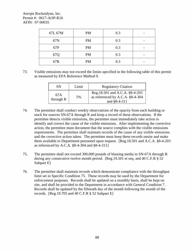
Aerojet Rocketdyne, Inc. Permit #: 0617-AOP-R16 AFIN: 07-00035
88
67L 67M PM 0.3 -
67N PM 0.3 -
67P PM 0.3 -
67Q PM 0.3 -
67R PM 0.3 -
73. Visible emissions may not exceed the limits specified in the following table of this permit as measured by EPA Reference Method 9.
SN Limit Regulatory Citation
67A through R 5%
Reg.18.501 and A.C.A. §8-4-203 as referenced by A.C.A. §8-4-304
and §8-4-311 74. The permittee shall conduct weekly observations of the opacity from each building or
stack for sources SN-67A through R and keep a record of these observations. If the permittee detects visible emissions, the permittee must immediately take action to identify and correct the cause of the visible emissions. After implementing the corrective action, the permittee must document that the source complies with the visible emissions requirements. The permittee shall maintain records of the cause of any visible emissions and the corrective action taken. The permittee must keep these records onsite and make them available to Department personnel upon request. [Reg.18.501 and A.C.A. §8-4-203 as referenced by A.C.A. §8-4-304 and §8-4-311]
75. The permittee shall not exceed 300,000 pounds of blasting media in SN-67A through R
during any consecutive twelve month period. [Reg.19.501 et seq. and 40 C.F.R § 52 Subpart E]
76. The permittee shall maintain records which demonstrate compliance with the throughput
limit set in Specific Condition 75. These records may be used by the Department for enforcement purposes. Records shall be updated on a monthly basis, shall be kept on site, and shall be provided to the Department in accordance with General Condition 7. Records shall be updated by the fifteenth day of the month following the month of the records. [Reg.19.705 and 40 C.F.R § 52 Subpart E]
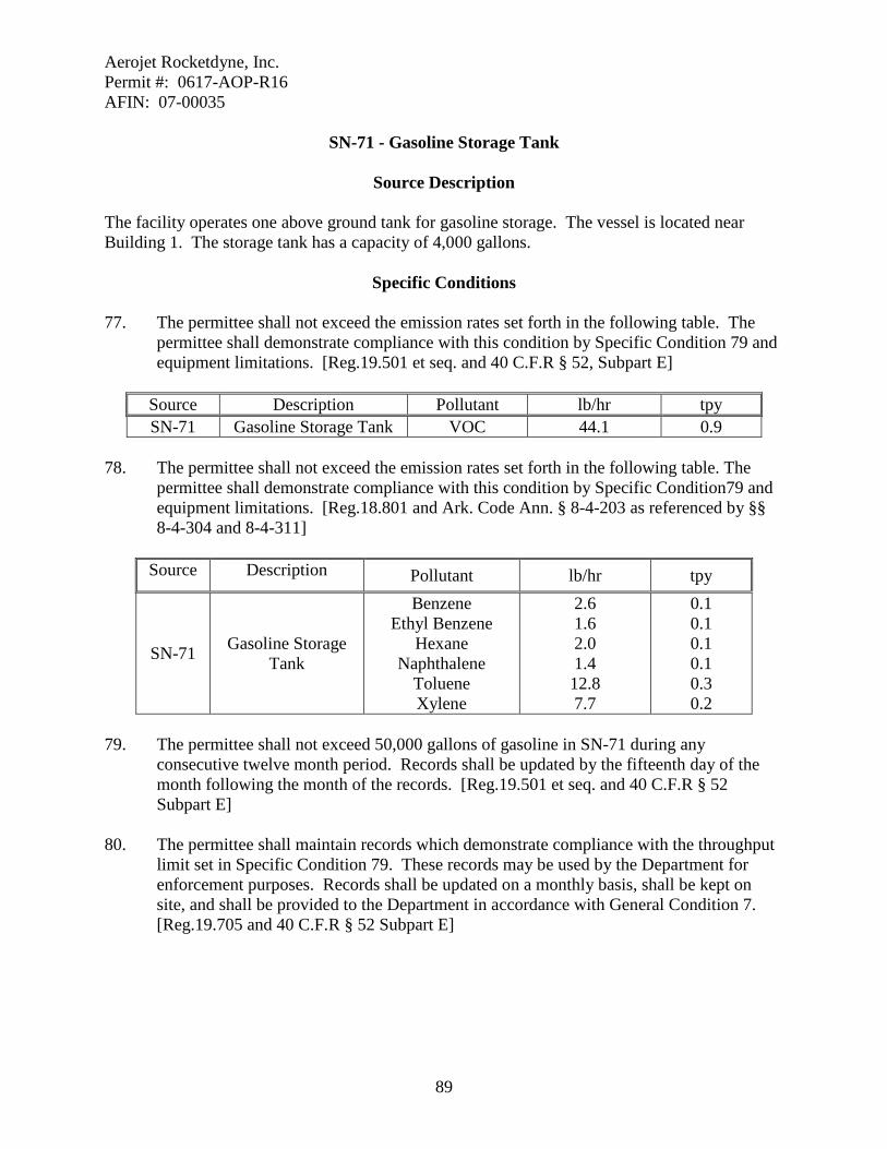
Aerojet Rocketdyne, Inc. Permit #: 0617-AOP-R16 AFIN: 07-00035
89
SN-71 - Gasoline Storage Tank
Source Description The facility operates one above ground tank for gasoline storage. The vessel is located near Building 1. The storage tank has a capacity of 4,000 gallons.
Specific Conditions 77. The permittee shall not exceed the emission rates set forth in the following table. The
permittee shall demonstrate compliance with this condition by Specific Condition 79 and equipment limitations. [Reg.19.501 et seq. and 40 C.F.R § 52, Subpart E]
Source Description Pollutant lb/hr tpy SN-71 Gasoline Storage Tank VOC 44.1 0.9
78. The permittee shall not exceed the emission rates set forth in the following table. The
permittee shall demonstrate compliance with this condition by Specific Condition79 and equipment limitations. [Reg.18.801 and Ark. Code Ann. § 8-4-203 as referenced by §§ 8-4-304 and 8-4-311]
Source Description Pollutant lb/hr tpy
SN-71 Gasoline Storage Tank
Benzene Ethyl Benzene
Hexane Naphthalene
Toluene Xylene
2.6 1.6 2.0 1.4 12.8 7.7
0.1 0.1 0.1 0.1 0.3 0.2
79. The permittee shall not exceed 50,000 gallons of gasoline in SN-71 during any
consecutive twelve month period. Records shall be updated by the fifteenth day of the month following the month of the records. [Reg.19.501 et seq. and 40 C.F.R § 52 Subpart E]
80. The permittee shall maintain records which demonstrate compliance with the throughput
limit set in Specific Condition 79. These records may be used by the Department for enforcement purposes. Records shall be updated on a monthly basis, shall be kept on site, and shall be provided to the Department in accordance with General Condition 7. [Reg.19.705 and 40 C.F.R § 52 Subpart E]

Aerojet Rocketdyne, Inc. Permit #: 0617-AOP-R16 AFIN: 07-00035
90
SN-72 - Diesel Fuel Storage Tanks
Source Description The facility operates two above-ground tanks for the storage of diesel fuel. The vessels are located near Building 1. The tanks have a capacity of 500 gallons each.
Specific Conditions 81. The permittee shall not exceed the emission rates set forth in the following table. The
permittee shall demonstrate compliance with this condition by Specific Condition 82 and equipment limitations. [Reg.19.501 et seq. and 40 C.F.R § 52, Subpart E]
Source Description Pollutant lb/hr tpy
SN-72 Diesel Storage Tank VOC 0.1 0.1 82. The permittee shall not exceed 40,000 gallons of diesel fuel in SN-72 during any
consecutive twelve month period. [Reg.19.501 et seq. and 40 C.F.R § 52 Subpart E] 83. The permittee shall maintain records which demonstrate compliance with the throughput
limit set in Specific Condition 82. These records may be used by the Department for enforcement purposes. Records shall be updated on a monthly basis, shall be kept on site, and shall be provided to the Department in accordance with General Condition 7. Records shall be updated by the fifteenth day of the month following the month of the records. [Reg.19.705 and 40 C.F.R § 52 Subpart E]
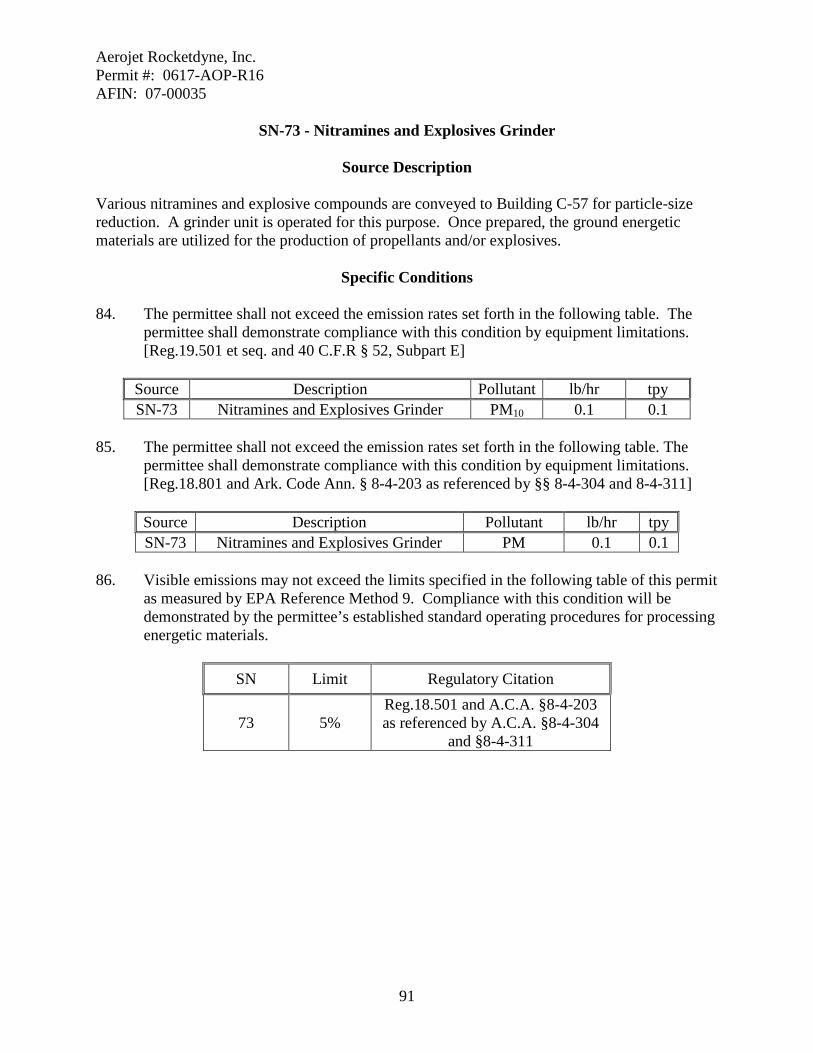
Aerojet Rocketdyne, Inc. Permit #: 0617-AOP-R16 AFIN: 07-00035
91
SN-73 - Nitramines and Explosives Grinder
Source Description Various nitramines and explosive compounds are conveyed to Building C-57 for particle-size reduction. A grinder unit is operated for this purpose. Once prepared, the ground energetic materials are utilized for the production of propellants and/or explosives.
Specific Conditions 84. The permittee shall not exceed the emission rates set forth in the following table. The
permittee shall demonstrate compliance with this condition by equipment limitations. [Reg.19.501 et seq. and 40 C.F.R § 52, Subpart E]
Source Description Pollutant lb/hr tpy SN-73 Nitramines and Explosives Grinder PM10 0.1 0.1
85. The permittee shall not exceed the emission rates set forth in the following table. The
permittee shall demonstrate compliance with this condition by equipment limitations. [Reg.18.801 and Ark. Code Ann. § 8-4-203 as referenced by §§ 8-4-304 and 8-4-311]
Source Description Pollutant lb/hr tpy SN-73 Nitramines and Explosives Grinder PM 0.1 0.1
86. Visible emissions may not exceed the limits specified in the following table of this permit
as measured by EPA Reference Method 9. Compliance with this condition will be demonstrated by the permittee’s established standard operating procedures for processing energetic materials.
SN Limit Regulatory Citation
73 5% Reg.18.501 and A.C.A. §8-4-203 as referenced by A.C.A. §8-4-304
and §8-4-311

Aerojet Rocketdyne, Inc. Permit #: 0617-AOP-R16 AFIN: 07-00035
92
SN-74 - Solvent Wipe Room Building M-2
Source Description The facility operates a solvent wipe room at Building M-2. The facility consists of an enclosed bay equipped with a vent hood. The wipe room is used for the hand-wipe degreasing of the rocket motor cases before and after installation of the case rubber. Several solvents are used as the cleaning agents and are manually applied using spray bottles and/or wiping cloths. This source is not subject to 40 C.F.R 63, Subpart T because it is a hand-wipe cleaning activity.
Specific Conditions 87. The permittee shall not exceed the emission rates set forth in the following table. The
permittee shall demonstrate compliance with this condition by Plantwide Condition 7 and equipment limitations. [Reg.19.501 et seq. and 40 C.F.R § 52, Subpart E]
Source Description Pollutant lb/hr tpy SN-74 Solvent Wipe Room Building M-2 VOC 8.5 2.2
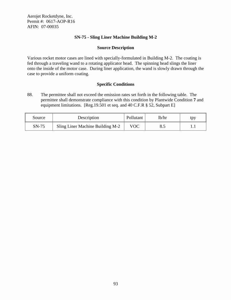
Aerojet Rocketdyne, Inc. Permit #: 0617-AOP-R16 AFIN: 07-00035
93
SN-75 - Sling Liner Machine Building M-2
Source Description Various rocket motor cases are lined with specially-formulated in Building M-2. The coating is fed through a traveling wand to a rotating applicator head. The spinning head slings the liner onto the inside of the motor case. During liner application, the wand is slowly drawn through the case to provide a uniform coating.
Specific Conditions 88. The permittee shall not exceed the emission rates set forth in the following table. The
permittee shall demonstrate compliance with this condition by Plantwide Condition 7 and equipment limitations. [Reg.19.501 et seq. and 40 C.F.R § 52, Subpart E]
Source Description Pollutant lb/hr tpy
SN-75 Sling Liner Machine Building M-2 VOC 8.5 1.1

Aerojet Rocketdyne, Inc. Permit #: 0617-AOP-R16 AFIN: 07-00035
94
SN-76A and 76B - Adhesive Primer Operations
Source Description Adhesive Primer Operations are located in Building M-8, SN-76B and Building M-2, SN-76A. Interior surfaces of clean, dry rocket motor cases are coated with an adhesive primer. The primer is applied using spray nozzles mounted on an automated, traveling wand.
Specific Conditions 89. The permittee shall not exceed the emission rates set forth in the following table. The
permittee shall demonstrate compliance with this condition by Plantwide Conditions 7, 17, and 19 and equipment limitations. [Reg.19.501 et seq. and 40 C.F.R § 52, Subpart E] Source Description Pollutant lb/hr tpy
SN-76A Adhesive Primer
Operations
PM10 VOC Lead
0.1 14.3 0.01
0.1 3.0 0.01
SN-76B PM10 VOC Lead
0.1 14.3 0.01
90. The permittee shall not exceed the emission rates set forth in the following table. The
permittee shall demonstrate compliance with this condition by Plantwide Conditions 7, 17, and 19 and equipment limitations. [Reg.18.801 and Ark. Code Ann. § 8-4-203 as referenced by §§ 8-4-304 and 8-4-311] Source Description Pollutant lb/hr tpy
SN-76A Adhesive
Primer Operations
PM 1,2-Butylene Oxide
Ethyl Benzene Formaldehyde
Methanol Methyl Isobutyl Ketone
Tetrachloroethylene Toluene
1,1,1-Trichloroethane Trichloroethylene
Xylene
0.1 0.3 1.5 0.1 1.2 3.8 0.9 1.5 3.2 2.3 4.9
0.1 0.2 0.6 0.1 0.5 1.5 0.4 0.6 1.3 1.0 2.0

Aerojet Rocketdyne, Inc. Permit #: 0617-AOP-R16 AFIN: 07-00035
95
Source Description Pollutant lb/hr tpy
SN-76B
PM 1,2-Butylene Oxide
Ethyl Benzene Formaldehyde
Methanol Methyl Isobutyl Ketone
Tetrachloroethylene Toluene
1,1,1-Trichloroethane Trichloroethylene
Xylene
0.1 0.3 1.5 0.1 1.2 3.8 0.9 1.5 3.2 2.3 4.9

Aerojet Rocketdyne, Inc. Permit #: 0617-AOP-R16 AFIN: 07-00035
96
SN-77A and 77B - Adhesive Operations
Source Description Following the application of the adhesive primer, adhesive is applied to the interior surfaces of the rocket motor cases. Adhesive Operations, SN-77A, is located in Building M-8 and SN-77B is located in Building M-2. The adhesive is applied by spray nozzles mounted on an automated, traveling wand. Plantwide Condition 7 lists available solvents and VOC/HAP compositions. Plantwide Condition 19 lists available adhesive VOC/HAP compositions.
Specific Conditions 91. The permittee shall not exceed the emission rates set forth in the following table. The
permittee shall demonstrate compliance with this condition by Plantwide Conditions 7, 17, and 19 and equipment limitations. [Reg.19.501 et seq. and 40 C.F.R § 52, Subpart E]
Source Description Pollutant lb/hr tpy
SN-77A Adhesive
Operations
PM10 VOC Lead
0.1 14.3 0.01 0.1
3.0 0.01 SN-77B
PM10 VOC Lead
0.1 14.3 0.01
92. The permittee shall not exceed the emission rates set forth in the following table. The
permittee shall demonstrate compliance with this condition by Plantwide Conditions 7, 17, and 19 and equipment limitations. [Reg.18.801 and Ark. Code Ann. § 8-4-203 as referenced by §§ 8-4-304 and 8-4-311]
Source Description Pollutant lb/hr tpy
SN-77A Adhesive Operations
PM 1,2-Butylene Oxide
Ethyl Benzene Formaldehyde
Methanol Methyl Isobutyl Ketone
Tetrachloroethylene Toluene
1,1,1-Trichloroethane Trichloroethylene
Xylene
0.1 0.3 1.5 0.1 1.2 3.8 0.9 1.5 3.2 2.3 4.9
0.1 0.2 0.6 0.1 0.5 1.5 0.4 0.6 1.3 1.0 2.0

Aerojet Rocketdyne, Inc. Permit #: 0617-AOP-R16 AFIN: 07-00035
97
Source Description Pollutant lb/hr tpy
SN-77B Adhesive Operations
PM 1,2-Butylene Oxide
Ethyl Benzene Formaldehyde
Methanol Methyl Isobutyl Ketone
Tetrachloroethylene Toluene
1,1,1-Trichloroethane Trichloroethylene
Xylene
0.1 0.3 1.5 0.1 1.2 3.8 0.9 1.5 3.2 2.3 4.9
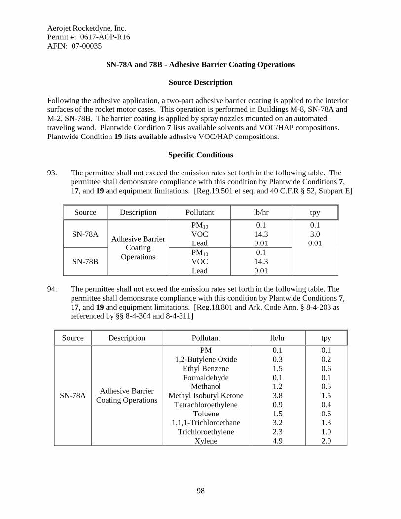
Aerojet Rocketdyne, Inc. Permit #: 0617-AOP-R16 AFIN: 07-00035
98
SN-78A and 78B - Adhesive Barrier Coating Operations
Source Description Following the adhesive application, a two-part adhesive barrier coating is applied to the interior surfaces of the rocket motor cases. This operation is performed in Buildings M-8, SN-78A and M-2, SN-78B. The barrier coating is applied by spray nozzles mounted on an automated, traveling wand. Plantwide Condition 7 lists available solvents and VOC/HAP compositions. Plantwide Condition 19 lists available adhesive VOC/HAP compositions.
Specific Conditions 93. The permittee shall not exceed the emission rates set forth in the following table. The
permittee shall demonstrate compliance with this condition by Plantwide Conditions 7, 17, and 19 and equipment limitations. [Reg.19.501 et seq. and 40 C.F.R § 52, Subpart E] Source Description Pollutant lb/hr tpy
SN-78A Adhesive Barrier Coating
Operations
PM10 VOC Lead
0.1 14.3 0.01
0.1 3.0 0.01
SN-78B PM10 VOC Lead
0.1 14.3 0.01
94. The permittee shall not exceed the emission rates set forth in the following table. The
permittee shall demonstrate compliance with this condition by Plantwide Conditions 7, 17, and 19 and equipment limitations. [Reg.18.801 and Ark. Code Ann. § 8-4-203 as referenced by §§ 8-4-304 and 8-4-311]
Source Description Pollutant lb/hr tpy
SN-78A Adhesive Barrier Coating Operations
PM 1,2-Butylene Oxide
Ethyl Benzene Formaldehyde
Methanol Methyl Isobutyl Ketone
Tetrachloroethylene Toluene
1,1,1-Trichloroethane Trichloroethylene
Xylene
0.1 0.3 1.5 0.1 1.2 3.8 0.9 1.5 3.2 2.3 4.9
0.1 0.2 0.6 0.1 0.5 1.5 0.4 0.6 1.3 1.0 2.0
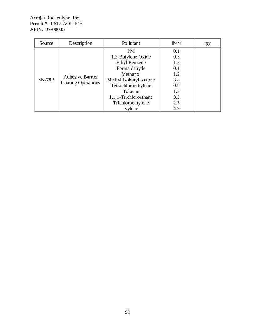
Aerojet Rocketdyne, Inc. Permit #: 0617-AOP-R16 AFIN: 07-00035
99
Source Description Pollutant lb/hr tpy
SN-78B Adhesive Barrier Coating Operations
PM 1,2-Butylene Oxide
Ethyl Benzene Formaldehyde
Methanol Methyl Isobutyl Ketone
Tetrachloroethylene Toluene
1,1,1-Trichloroethane Trichloroethylene
Xylene
0.1 0.3 1.5 0.1 1.2 3.8 0.9 1.5 3.2 2.3 4.9

Aerojet Rocketdyne, Inc. Permit #: 0617-AOP-R16 AFIN: 07-00035
100
SN-80 - Warhead Coating Operation
Source Description The inside surface of the warhead cases are coated with a thin film of a Teflon-based release-agent. A propellant mixture is then cast (i.e., loaded) into the prepared cases in Building C-50. The units are subsequently cured in a steam or hot water-heated oven in Building C-61. Plantwide Condition 7 lists available solvents and VOC/HAP compositions and Plantwide Condition 11 lists available paint VOC/HAP compositions.
Specific Conditions 95. The permittee shall not exceed the emission rates set forth in the following table. The
permittee shall demonstrate compliance with this condition by Plantwide Conditions 7, 9, 11 and equipment limitations. [Reg.19.501 et seq. and 40 C.F.R § 52, Subpart E]
Source Description Pollutant lb/hr tpy
SN-80 Warhead Coating Operation VOC 1.0 0.3
96. The permittee shall not exceed the emission rates set forth in the following table. The
permittee shall demonstrate compliance with this condition by Plantwide Conditions 7, 17, and 19 and equipment limitations. [Reg.18.801 and Ark. Code Ann. § 8-4-203 as referenced by §§ 8-4-304 and 8-4-311] Source Description Pollutant lb/hr tpy
SN-80 Warhead Coating Operation CFC-113 6.6 2.0

Aerojet Rocketdyne, Inc. Permit #: 0617-AOP-R16 AFIN: 07-00035
101
SN-81 - Diesel-Powered Pump at Rocket Motor Case Washout Facility
Source Description Solid propellant is removed from off-specification/ unusable rocket motor cases so that the metal cases can be reused. The propellant is extracted using a high-pressure spray of water. The pump for the Ahydrolance@ machine is powered by a diesel-fired internal combustion engine. This pump has a maximum power rating of 300 hp and consumes 15 gallons of fuel per hour.
Specific Conditions 97. The permittee shall not exceed the emission rates set forth in the following table. The
permittee shall demonstrate compliance with this condition by Specific Condition 101 and equipment limitations. [Reg.19.501 et seq. Regulation 19 and 40 C.F.R § 52, Subpart E]
Source Description Pollutant lb/hr tpy
SN-81 Diesel-Powered Pump
PM10 SO2 VOC CO NOx
0.7 0.7 0.8 2.0 9.2
2.9 2.7 3.3 8.7 40.0
98. The permittee shall not exceed the emission rates set forth in the following table. The
permittee shall demonstrate compliance with this condition by Specific Condition 101 and equipment limitations. [Reg.18.801 and Ark. Code Ann. § 8-4-203 as referenced by §§ 8-4-304 and 8-4-311]
Source Description Pollutant lb/hr tpy
SN-81 Diesel-Powered Pump
PM Acetaldehyde
Acrolein Benzene
1,3 Butadiene Formaldehyde
PAHs Toluene Xylene
0.7 0.1 0.1 0.1 0.1 0.1 0.1 0.1 0.1
2.9 0.1 0.1 0.1 0.1 0.1 0.1 0.1 0.1
99. Visible emissions may not exceed the limits specified in the following table of this permit
as measured by EPA Reference Method 9.

Aerojet Rocketdyne, Inc. Permit #: 0617-AOP-R16 AFIN: 07-00035
102
SN Limit Regulatory Citation
81 20% Reg.18.501 and A.C.A. §8-4-203 as referenced by A.C.A. §8-4-304
and §8-4-311 100. The permittee shall conduct daily observations of the opacity from source SN-81 on those
days when the equipment is in operation and keep a record of these observations. If the permittee detects visible emissions, the permittee must immediately take action to identify and correct the cause of the visible emissions. After implementing the corrective action, the permittee must document that the source complies with the visible emissions requirements. The permittee shall maintain records of the cause of any visible emissions and the corrective action taken. The permittee must keep these records onsite and make them available to Department personnel upon request. [Reg.18.501 and A.C.A. §8-4-203 as referenced by A.C.A. §8-4-304 and §8-4-311]
101. The permittee shall not use in excess of 131,400 gallons of diesel fuel in SN-81 during
any consecutive twelve month period. [Reg.19.501 et seq. and 40 C.F.R § 52 Subpart E] 102. The permittee shall maintain records which demonstrate compliance with the throughput
limit set in Specific Condition 101. These records may be used by the Department for enforcement purposes. Records shall be updated on a monthly basis, shall be kept on site, and shall be provided to the Department in accordance with General Condition 7. Records shall be updated by the fifteenth day of the month following the month of the records. [Reg.19.705 and 40 C.F.R § 52 Subpart E]
103. The permittee shall for SN-81 maintain emissions less than 230 ppm at 15% O2 on a dry basis. [Reg.19.304 and 40 C.F.R Part 63, Subpart ZZZZ]
104. The permittee shall test SN-81 initially for CO in accordance with 40 C.F.R 63.6612, 63.6620, 63.7(a)(2) and General Provision 7. [Reg.19.304 and 40 C.F.R Part 63, Subpart ZZZZ]
105. The permittee shall for SN-81 change the oil and filter every 500 hours or annually whichever comes first, Inspect air cleaner every 1,000 hours or annually whichever comes first and replace if necessary, inspect all hoses and belts every 500 hours of operation or annually whichever comes first and replace as necessary. [Reg.19.304 and 40 C.F.R Part 63, Subpart ZZZZ]
106. The permittee shall install a non-resettable hour meter on SN-81 if one is not already
installed. [Reg.19.304 and 40 C.F.R Part 63, Subpart ZZZZ] 107. The permittee shall for SN-81 operate the engine according to the manufacturer’s
emission related written instructions. The engine must be operated and maintained in a
Aerojet Rocketdyne, Inc. Permit #: 0617-AOP-R16 AFIN: 07-00035
103
manner consistent with safety and good air pollution control practices for minimizing emissions. [Reg.19.304 and 40 C.F.R Part 63, Subpart ZZZZ]
108. The permittee shall for SN-81 minimize engine’s time spent at idle during start up and
minimize the engine’s start-up time to a period needed for safe loading of the engine, not to exceed 30 minutes. [Reg.19.304 and 40 C.F.R Part 63, Subpart ZZZZ]
109. The operating limitations and emission limits of 40 C.F.R 63 Subpart ZZZZ apply to SN-
81 at all times. [Reg.19.304 and 40 C.F.R Part 63, Subpart ZZZZ] 110. The permittee must maintain records of all required maintenance on SN-81 and records
of occurrence and duration of each malfunction. [Reg.19.304 and 40 C.F.R Part 63, Subpart ZZZZ]
111. The permittee must maintain records required in 40 C.F.R 63.6655 and 63.6660 as
required for SN-81. [Reg.19.304 and 40 C.F.R Part 63, Subpart ZZZZ] 112. The permittee must submit a semiannual compliance report for SN-81 in accordance with
40 C.F.R 63.6650. [Reg.19.304 and 40 C.F.R Part 63, Subpart ZZZZ]

Aerojet Rocketdyne, Inc. Permit #: 0617-AOP-R16 AFIN: 07-00035
104
SN-84 - Warhead Manufacturing Operations
Source Description The facility makes a variety of warheads and ordnance at Building M-11. A barrier coating (asphalt or wax) is first applied to the inside of the prepared metal cases. The components are then filled with explosives. The units are subsequently cured in a steam-heated oven. The warheads and ordnance are then moved to other buildings for finishing and final assembly. Two propane-fired “melter/applicator machines” are used to apply the barrier coatings. A small natural gas-fired boiler provides steam and hot water for the production equipment.
Specific Conditions 113. The permittee shall not exceed the emission rates set forth in the following table. The
permittee shall demonstrate compliance with this condition by Specific Conditions 116 and 118, equipment limitations, and by burning only natural gas and propane. [Reg.19.501 et seq. and 40 C.F.R § 52, Subpart E]
Source Description Pollutant lb/hr tpy
SN-84 Warhead Manufacturing Operations
PM10 SO2 VOC CO NOx
0.1 0.1 10.1 0.3 0.4
0.2 0.1 1.7 1.3 1.7
114. The permittee shall not exceed the emission rates set forth in the following table. The
permittee shall demonstrate compliance with this condition by equipment limitations and by burning only natural gas and propane. [Reg.18.801 and A.C.A. §8-4-203 as referenced by §8-4-304 and §8-4-311]
Source Description Pollutant lb/hr tpy
SN-84 Warhead
Manufacturing Operations
PM HAPs
0.1 0.01
0.2 0.01
115. Visible emissions may not exceed the limits specified in the following table of this permit
as measured by EPA Reference Method 9. Compliance will be demonstrated by burning only natural gas and propane.
SN Limit Regulatory Citation
84 5% Reg.18.501 and A.C.A. §8-4-203 as referenced by A.C.A. §8-4-304 and §8-4-311

Aerojet Rocketdyne, Inc. Permit #: 0617-AOP-R16 AFIN: 07-00035
105
116. The permittee shall not use in excess of 15,000 pounds of asphalt coating in SN-84 during any consecutive twelve month period. [Reg.19.501 et seq. and 40 C.F.R § 52 Subpart E]
117. The permittee shall maintain records which demonstrate compliance with the throughput
limit set in Specific Condition 116. These records may be used by the Department for enforcement purposes. Records shall be updated on a monthly basis, shall be kept on site, and shall be provided to the Department in accordance with General Condition 7. Records shall be updated by the fifteenth day of the month following the month of the records. [Reg.19.705 and 40 C.F.R § 52 Subpart E]
118. The permittee shall not use in excess of 15,000 pounds of wax coatings in SN-84 during
any consecutive twelve month period. [Reg.19.501 et seq. and 40 C.F.R § 52 Subpart E] 119. The permittee shall maintain records which demonstrate compliance with the throughput
limit set in Specific Condition 118. These records may be used by the Department for enforcement purposes. Records shall be updated on a monthly basis, shall be kept on site, and shall be provided to the Department in accordance with General Condition 7. Records shall be updated by the fifteenth day of the month following the month of the records. [Reg.19.705 and 40 C.F.R § 52 Subpart E]

Aerojet Rocketdyne, Inc. Permit #: 0617-AOP-R16 AFIN: 07-00035
106
SN-85 - Motor Case Cleaning Operations
Source Description Metal rocket motor cases are cleaned at Building M-8 to prepare them for adhesive bonding, surface coating, and/or lining. Residual oil and grease are removed by hand-wipe cleaning. Certain motor cases are cleaned using a special flushing-cleaning apparatus. Plantwide Condition 7 lists available solvents and VOC/HAP compositions. This source is not subject to 40 C.F.R 63, Subpart T because these provisions do not regulate the use of halogenated solvents in hand-wipe cleaning activities. In addition, the motor case flush-cleaning apparatus is not subject to Subpart T because halogenated solvents are not used in this equipment.
Specific Conditions 120. The permittee shall not exceed the emission rates set forth in the following table. The
permittee shall demonstrate compliance with this condition by Plantwide Condition 7 and equipment limitations. [Reg.19.501 et seq. and 40 C.F.R § 52, Subpart E]
Source Description Pollutant lb/hr tpy
SN-85 Motor Case Cleaning Operations VOC 17.0 2.2 121. The permittee shall not exceed the emission rates set forth in the following table. The
permittee shall demonstrate compliance with this condition by Plantwide Condition 7 and equipment limitations. [Reg.18.801 and Ark. Code Ann. § 8-4-203 as referenced by §§ 8-4-304 and 8-4-311]
Source Description Pollutant lb/hr tpy
SN-85 Motor Case Cleaning Operations
Methylene Chloride 1,1,1-Trichloroethane
11.0 10.9
2.8 2.8

Aerojet Rocketdyne, Inc. Permit #: 0617-AOP-R16 AFIN: 07-00035
107
SN-86, SN-87, SN-89, SN-90, SN-91, SN-92, SN-93, SN-95, SN-102, SN-103, SN104, SN-105, and SN-106 Emergency Power Generators
Source Description
SN-86 is a propane-fired emergency power generator located at the Guard House. The engine is rated at 18 hp and the generator is rated at 10 kW. SN-87 is a natural gas-fired emergency generator located at Building 61. This engine is rated at 225 hp and the generator is rated at 150 kW. SN-89 is a natural gas-fired emergency generator located at Building M-142. This engine is rated at 193 hp and the generator is rated at 125 kW. SN-90 is a natural gas-fired emergency generator located at Building M-8. This engine is rated at 135 hp and the generator is rated at 100 kW. SN-91 is a diesel-fired emergency generator located at Building 66. This engine is rated at 170 hp and the generator is rated at 100 kW. SN-92 is a diesel-fired emergency generator located at Building M-2. This engine is rated at 535 hp and the generator is rated at 350 kW. SN-93 is a diesel-fired emergency generator located at Building M-11. This engine is rated at 193 hp and the generator is rated at 125 kW. SN-95 is a natural gas-fired emergency generator located at building M-125. This engine is rated at 24 hp and the generator is rated at 18 kW. SN-102 is a 250 kW natural gas-fired generator located at building 101. SN-103 is an 80 kW natural gas-fired generator located at Building 102. SN-105 is the NG Emergency Generator at 2-SH-9. It is a 310 hp natural gas-fired engine. SN-106 is a 402.3 hp diesel-fired emergency generator located at building M-14.
Specific Conditions 122. The permittee shall not exceed the emission rates set forth in the following table. The
permittee shall demonstrate compliance with this condition by compliance with Specific Condition 125. [Reg.19.501 et seq. and 40 C.F.R. § 52 Subpart E]

Aerojet Rocketdyne, Inc. Permit #: 0617-AOP-R16 AFIN: 07-00035
108
SN Description Pollutant lb/hr tpy
SN-86 Emergency Power
Generator (Guard House)
PM10 SO2 VOC CO NOx
0.1 0.1 0.1 0.7 0.4
0.1 0.1 0.1 0.2 0.1
SN-87 Emergency Power
Generator (Building 61)
PM10 SO2 VOC CO NOx
0.1 0.1 0.1 7.4 4.4
0.1 0.1 0.1 1.9 1.1
89 Emergency Power Generator Building
M-142
PM10 SO2 VOC CO NOx
0.1 0.1 0.1 5.9 3.5
0.1 0.1 0.1 1.5 0.9
90 Emergency Power Generator Building
M-8
PM10 SO2 VOC CO NOx
0.1 0.1 0.1 4.2 2.5
0.1 0.1 0.1 1.1 0.7
91 Emergency Power Generator Building
66
PM10 SO2 VOC CO NOx
0.7 0.7 0.8 2.1 9.8
0.2 0.2 0.2 0.6 2.5
92 Emergency Power Generator Building
M-2
PM10 SO2 VOC CO NOx
1.2 1.1 1.3 3.5 15.9
0.3 0.3 0.4 0.9 4.0
93 Emergency Power Generator Building
M-11
PM10 SO2 VOC CO NOx
0.1 0.1 0.1 5.9 3.5
0.1 0.1 0.1 1.5 0.9
95 Emergency Power
Generator M-125
PM10 SO2 VOC CO NOx
0.1 0.1 0.1 24.1 0.4
0.1 0.1 0.1 6.1 0.1
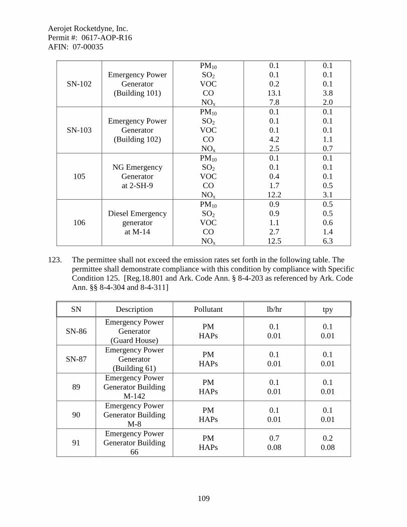
Aerojet Rocketdyne, Inc. Permit #: 0617-AOP-R16 AFIN: 07-00035
109
SN-102 Emergency Power
Generator (Building 101)
PM10 SO2 VOC CO NOx
0.1 0.1 0.2 13.1 7.8
0.1 0.1 0.1 3.8 2.0
SN-103 Emergency Power
Generator (Building 102)
PM10 SO2 VOC CO NOx
0.1 0.1 0.1 4.2 2.5
0.1 0.1 0.1 1.1 0.7
105 NG Emergency
Generator at 2-SH-9
PM10 SO2 VOC CO NOx
0.1 0.1 0.4 1.7 12.2
0.1 0.1 0.1 0.5 3.1
106 Diesel Emergency
generator at M-14
PM10 SO2 VOC CO NOx
0.9 0.9 1.1 2.7 12.5
0.5 0.5 0.6 1.4 6.3
123. The permittee shall not exceed the emission rates set forth in the following table. The
permittee shall demonstrate compliance with this condition by compliance with Specific Condition 125. [Reg.18.801 and Ark. Code Ann. § 8-4-203 as referenced by Ark. Code Ann. §§ 8-4-304 and 8-4-311]
SN Description Pollutant lb/hr tpy
SN-86 Emergency Power
Generator (Guard House)
PM HAPs
0.1 0.01
0.1 0.01
SN-87 Emergency Power
Generator (Building 61)
PM HAPs
0.1 0.01
0.1 0.01
89 Emergency Power Generator Building
M-142
PM HAPs
0.1 0.01
0.1 0.01
90 Emergency Power Generator Building
M-8
PM HAPs
0.1 0.01
0.1 0.01
91 Emergency Power Generator Building
66
PM HAPs
0.7 0.08
0.2 0.08

Aerojet Rocketdyne, Inc. Permit #: 0617-AOP-R16 AFIN: 07-00035
110
92 Emergency Power Generator Building
M-2
PM HAPs
1.2 0.08
0.3 0.08
93 Emergency Power Generator Building
M-11
PM HAPs
0.1 0.03
0.1 0.03
95 Emergency Power Generator - M-125
PM HAPs
0.1 0.01
0.1 0.01
SN-102 Emergency Power
Generator (Building 101)
PM HAPs
0.1 0.37
0.1 0.09
SN-103 Emergency Power
Generator (Building 102)
PM HAPs
0.1 0.12
0.1 0.03
105 NG Emergency
Generator at 2-SH-9
PM HAPs
0.1 0.01
0.1 0.01
106 Diesel Emergency
generator at M-14
PM HAPs
0.9 0.01
0.5 0.01
124. Visible emissions may not exceed the limits specified in the following table of this permit
as measured by EPA Reference Method 9. SN Limit Regulatory Citation
SN-86 SN-87 SN-89 SN-90 SN-95 SN-102 SN-103 SN-105
5% Reg.18.501 and A.C.A. §8-4-203 as referenced by A.C.A. §8-4-304
and §8-4-311
SN-91 SN-92 SN-93 SN-106
20% Reg.19.503 and 40 C.F.R § 52, Subpart E
125. The permittee shall not operate the Emergency Power Generators, SN-86, SN-87, SN-89,
SN-95, SN-102, SN-103, SN-105, and SN-106 more than 500 hours each per consecutive 12 month period. [Reg.19.501 et seq. and 40 C.F.R § 52 Subpart E]
126. The permittee shall maintain monthly records of the hours of operation of SN-86, SN-87,
SN-89, SN-95, SN-102, and SN-103. These records shall be kept in accordance with

Aerojet Rocketdyne, Inc. Permit #: 0617-AOP-R16 AFIN: 07-00035
111
General Provision 7, kept on site and made available to Department personnel upon request. Records shall be updated by the fifteenth day of the month following the month of the records. [Reg.19.705 and 40 C.F.R § 52 Subpart E]
127. The Emergency Power Generators, SN-86, SN-87, SN-89, SN-95, SN-102, and SN-103,
are subject to and shall comply with the provisions of NSPS Subpart JJJJ. SN-86, SN-87, SN-89, SN-95, SN-102, and SN-103 are also subject to 40 C.F.R Part 63 Subpart ZZZZ. Compliance with Subpart ZZZZ is demonstrated by complying with NSPS Subpart JJJJ. [Reg.19.304 of Regulation 19, 40 C.F.R Part 60 Subpart JJJJ, and 40 C.F.R Part 63 Subpart ZZZZ]
128. SN-86, SN-87, SN-89, SN-95, SN-102, and SN-103 shall comply with the emission
standards of 60.4231(a). The permittee must operate SN-86, SN-87, SN-89, SN-95, SN-102, and SN-103 so that they comply with those standards over the entire life of the engine. [Reg.19.304 and 40 C.F.R '' 60.4233(a) and 60.4234]
129. If the Emergency Generators, SN-86, SN-87, SN-89, SN-95, SN-102, and SN-103, do not
meet the standards applicable to non-emergency engines, the permittee must install a non-resettable hour meter upon start-up of the engines. [Reg.19.304 and 40 C.F.R ' 60.4237(c)]
130. If the permittee operates and maintains the certified stationary SI internal combustion
engine and control device according to the manufacturer's emission-related written instructions, the permittee must keep records of conducted maintenance to demonstrate compliance. If the permittee does not operate and maintain SN-86, SN-87, SN-89, SN-95, SN-102, and SN-103 according to the manufacturer's emission-related written instructions, the engine will be considered a non-certified engine, and you must demonstrate compliance by keeping a maintenance plan and records of conducted maintenance to demonstrate compliance and must, to the extent practicable, maintain and operate the engine in a manner consistent with good air pollution control practice for minimizing emissions. [Reg.19.304 and 40 C.F.R ' 60.4243(a)]
131. The permittee may operate the Emergency Generators, SN-86, SN-87, SN-89, SN-95,
SN-102, and SN-103 for the purpose of maintenance checks and readiness testing, provided that the tests are recommended by Federal, State or local government, the manufacturer, the vendor, or the insurance company associated with the engine. Maintenance checks and readiness testing of such units is limited to 100 hours per year. There is no NSPS required time limit on the use of emergency stationary ICE in emergency situations. The 500 hour of operation limit of the permit still applies. SN-86, SN-87, SN-89, SN-95, SN-102, and SN-103 may operate up to 50 hours per year in non-emergency situations, but those 50 hours are counted towards the 100 hours per year provided for maintenance and testing. The 50 hours per year for non-emergency situations cannot be used for peak shaving or to generate income for a facility to supply power to an electric grid or otherwise supply power as part of a financial arrangement with another entity. For owners and operators of emergency engines, any operation other

Aerojet Rocketdyne, Inc. Permit #: 0617-AOP-R16 AFIN: 07-00035
112
than emergency operation, maintenance and testing, and operation in non-emergency situations for 50 hours per year except as allowed in this paragraph is prohibited. [Reg.19.304 and 40 C.F.R ' 60.4243(d)]
132. The permittee shall for SN-90 change the oil and filter every 500 hours or annually whichever comes first, Inspect spark plugs every 1,000 hours or annually whichever comes first and replace if necessary, inspect all hoses and belts every 500 hours of operation or annually whichever comes first and replace as necessary. [Reg.19.304 and 40 C.F.R ' 63 Subpart ZZZZ]
133. The permittee shall for SN-91 and 93 change the oil and filter every 500 hours or annually whichever comes first, Inspect air cleaner every 1,000 hours or annually whichever comes first and replace if necessary, inspect all hoses and belts every 500 hours of operation or annually whichever comes first and replace as necessary. [Reg.19.304 and 40 C.F.R ' 63 Subpart ZZZZ]
134. The permittee shall install a non-resettable hour meter on SN-90, 91, and 93 if one is not
already installed. [Reg.19.304 and 40 C.F.R Part 63, Subpart ZZZZ] 135. The permittee shall for SN-90, 91, and 93 operate the engine according to the
manufacturer’s emission related written instructions. The engine must be operated and maintained in a manner consistent with safety and good air pollution control practices for minimizing emissions. [Reg.19.304 and 40 C.F.R Part 63, Subpart ZZZZ]
136. The permittee shall for SN-90, 91, and 93, minimize engine’s time spent at idle during
start up and minimize the engine’s start-up time to a period needed for safe loading of the engine, not to exceed 30 minutes. [Reg.19.304 and 40 C.F.R Part 63, Subpart ZZZZ]
137. The permittee not operate, SN-90, 91, and 93, more than 100 hours per calendar year for
the purposes of maintenance and readiness checks. The permittee may operate the engine up to 50 hours per calendar year in non-emergency situations. Those 50 hours count toward the 100 hours for maintenance and readiness checks. [Reg.19.304 and 40 C.F.R Part 63, Subpart ZZZZ]
138. The operating limitations of 40 C.F.R 63 Subpart ZZZZ apply to SN-90, 91, 93 at all
times. [Reg.19.304 and 40 C.F.R Part 63, Subpart ZZZZ] 139. The permittee must maintain records of all required maintenance on SN-90, 91, and 93
and records of occurrence and duration of each malfunction. [Reg.19.304 and 40 C.F.R Part 63, Subpart ZZZZ]
140. The permittee must maintain records of the hours of operation of SN-90, 91, and 93 document how many hours are spent for emergency operation, including what classified the operation as emergency, and how many hours are spent for non-emergency operation. [Reg.19.304 and 40 C.F.R Part 63, Subpart ZZZZ]

Aerojet Rocketdyne, Inc. Permit #: 0617-AOP-R16 AFIN: 07-00035
113
SN-98 – Spray Liner Operation at Building M-125
Source Description The Spray Liner Operation at Building M-125 applies a specially formulated polyurethane coating to the inside of rocket motor casings. The coating can be mixed with VOC-based solvent or acetone.
Specific Conditions 141. The permittee shall not exceed the emission rates set forth in the following table. The
permittee shall demonstrate compliance with this condition by compliance with Specific Condition 144. [Reg.19.501 et seq. and 40 C.F.R. § 52 Subpart E]
SN Description Pollutant lb/hr tpy
SN-98 Spray Liner
Operation Building M-125
PM10 VOC
0.1 15.5
0.1 6.9
142. The permittee shall not exceed the emission rates set forth in the following table. The
permittee shall demonstrate compliance with this condition by compliance with Specific Condition 144. [Reg.18.801 and Ark. Code Ann. § 8-4-203 as referenced by Ark. Code Ann. §§ 8-4-304 and 8-4-311]
SN Description Pollutant lb/hr tpy
98 Spray Liner
Operation Building M-125
PM Acetone
0.1 13.2
0.1 6.2
143. Visible emissions may not exceed the limits specified in the following table of this permit
as measured by EPA Reference Method 9.
SN Limit Regulatory Citation
SN-98 5% Reg.19.503 and 40 C.F.R. § 52 Subpart E
144. The permittee shall not apply more than 1500 gallons of liner material in any consecutive
12 month period. The liner material shall not have a VOC content more than 7 lb/gal. The liner material may also contain acetone with no content limit. [Reg.19.501 et seq. and 40 C.F.R § 52 Subpart E]
145. The permittee shall keep monthly records of liner material used and VOC content. These records shall include the 12 month rolling total of liner material used, and the VOC

Aerojet Rocketdyne, Inc. Permit #: 0617-AOP-R16 AFIN: 07-00035
114
content of liner material. These records shall be updated by the 15th day of the month following the month to which the records pertain, kept in accordance with General Provision 7, on site, and made available to Department personnel upon request. [Reg.19.705 and 40 C.F.R § 52 Subpart E]

Aerojet Rocketdyne, Inc. Permit #: 0617-AOP-R16 AFIN: 07-00035
115
SN-99 - Spray Liner Machine (Building 102)
Source Description The spray liner machine in Building 102 is used to line the inside of rocket motor casings.
Specific Conditions 146. The permittee shall not exceed the emission rates set forth in the following table. The
permittee shall demonstrate compliance with this condition by compliance with Plantwide Condition 7, 17, and 19. [Reg.19.501 et seq. and 40 C.F.R. § 52 Subpart E]
SN Description Pollutant lb/hr tpy
SN-99 Spray Liner
Machine (Building 102)
PM10 VOC Lead
0.1 28.5 0.01
0.1 4.0 0.01
147. The permittee shall not exceed the emission rates set forth in the following table. The
permittee shall demonstrate compliance with this condition by compliance with Plantwide Condition 7, 17, and 19. [Reg.18.801 and Ark. Code Ann. § 8-4-203 as referenced by Ark. Code Ann. §§ 8-4-304 and 8-4-311]
SN Description Pollutant lb/hr tpy
SN-99
Spray Liner Machine (Building
102)
PM 1,2-Butylene Oxide
Ethyl Benzene Formaldehyde
Methanol Methyl Isobutyl Ketone
Tetrachloroethylene Toluene
1,1,1-Trichloroethane Trichloroethylene
Xylene
0.1 0.58 2.88 0.06 2.30 7.48 1.73 2.88 6.33 4.60 9.78
0.1 0.12 0.58 0.02 0.46 1.50 0.35 0.58 1.27 0.92 1.96
148. Visible emissions may not exceed the limits specified in the following table of this permit
as measured by EPA Reference Method 9.
SN Limit Regulatory Citation
SN-99 5% Reg.19.503 and 40 C.F.R. § 52 Subpart E

Aerojet Rocketdyne, Inc. Permit #: 0617-AOP-R16 AFIN: 07-00035
116
SN-100A and 100B - Floor Operations at Building 101 and Building 102
Source Description Floor operations include a variety of small-scale touch-up painting, adhesive bonding stenciling, gluing and hand wipe cleaning activities in the production of rocket motor casings. Specific Conditions 149. The permittee shall not exceed the emission rates set forth in the following table. The
permittee shall demonstrate compliance with this condition by compliance with Plantwide Condition 7, 9, 11, 15, 17, and 19. [Reg.19.501 et seq. and 40 C.F.R. § 52 Subpart E]
SN Description Pollutant lb/hr tpy
SN100A
Floor Operations (Building
101)
PM10 VOC Lead
0.1 19.7 0.01
0.1 9.9 0.01
SN-100B
Floor Operations (Building
102)
PM10 VOC Lead
0.1 19.7 0.01
150. The permittee shall not exceed the emission rates set forth in the following table. The
permittee shall demonstrate compliance with this condition by compliance with Plantwide Condition 7, 9, 11, 15, 17, and 19. [Reg.18.801 and Ark. Code Ann. § 8-4-203 as referenced by Ark. Code Ann. §§ 8-4-304 and 8-4-311]

Aerojet Rocketdyne, Inc. Permit #: 0617-AOP-R16 AFIN: 07-00035
117
SN Description Pollutant lb/hr tpy
SN100A Floor
Operations (Building 101)
PM Acetone
1,2-Butylene Oxide Chromium Cumene
DGMBEA DGMEEA
Ethyl Acrylate Ethyl Benzene Glycol Ethers
Methanol Methylene Chloride
Methyl Isobutyl Ketone Phenol Toluene
1,1,1-Trichloroethane Xylene
0.1 8.58 0.41 0.01 0.35 0.71 1.42 1.05 1.41 3.20 2.47 2.84 7.04 1.64 8.44 6.75 5.98
0.1 4.30 0.21 0.01 0.18 0.36 0.71 0.53 0.71 1.60 1.24 1.42 3.52 0.82 4.23 3.38 2.99
SN-100B Floor
Operations (Building 102)
PM Acetone
1,2-Butylene Oxide Chromium Cumene
DGMBEA DGMEEA
Ethyl Acrylate Ethyl Benzene Glycol Ethers
Methanol Methylene Chloride
Methyl Isobutyl Ketone Phenol Toluene
1,1,1-Trichloroethane Xylene
0.1 8.58 0.41 0.01 0.35 0.71 1.42 1.05 1.41 3.20 2.47 2.84 7.04 1.64 8.44 6.75 5.98
151. Visible emissions may not exceed the limits specified in the following table of this permit
as measured by EPA Reference Method 9.
SN Limit Regulatory Citation SN-100A SN-100B 5% Reg.19.503 and 40 C.F.R. § 52
Subpart E

Aerojet Rocketdyne, Inc. Permit #: 0617-AOP-R16 AFIN: 07-00035
118
SN-104 - Propellant Cutting Operation (Building C39)
Source Description After casting, rocket propellant is cut to provide stress relief. A vacuum system is utilized to capture propellant shavings.
Specific Conditions 152. The permittee shall not exceed the emission rates set forth in the following table. The
permittee shall demonstrate compliance with this condition by compliance with Plantwide Condition 5. [Reg.19.501 et seq. and 40 C.F.R. § 52 Subpart E]
SN Description Pollutant lb/hr tpy
SN-104 Propellant Cutting Operation (Building C39) PM10 0.1 0.1
153. The permittee shall not exceed the emission rates set forth in the following table. The
permittee shall demonstrate compliance with this condition by compliance with Plantwide Condition 5. [Reg.18.801 and Ark. Code Ann. § 8-4-203 as referenced by Ark. Code Ann. §§ 8-4-304 and 8-4-311]
SN Description Pollutant lb/hr tpy
SN-104 Propellant Cutting Operation (Building C39) PM 0.1 0.1
154. The Visible emissions may not exceed the limits specified in the following table of this
permit as measured by EPA Reference Method 9.
SN Limit Regulatory Citation
104 5% Reg.18.501 and A.C.A. §8-4-203 as referenced by A.C.A. §8-4-304
and §8-4-311

Aerojet Rocketdyne, Inc. Permit #: 0617-AOP-R16 AFIN: 07-00035
119

Aerojet Rocketdyne, Inc. Permit #: 0617-AOP-R16 AFIN: 07-00035
120
SECTION V: COMPLIANCE PLAN AND SCHEDULE
Aerojet Rocketdyne, Inc. will continue to operate in compliance with those identified regulatory provisions. The facility will examine and analyze future regulations that may apply and determine their applicability with any necessary action taken on a timely basis.

Aerojet Rocketdyne, Inc. Permit #: 0617-AOP-R16 AFIN: 07-00035
121
SECTION VI: PLANTWIDE CONDITIONS
1. The permittee shall notify the Director in writing within thirty (30) days after
commencing construction, completing construction, first placing the equipment and/or facility in operation, and reaching the equipment and/or facility target production rate. [Reg.19.704, 40 C.F.R. § 52 Subpart E, and Ark. Code Ann. § 8-4-203 as referenced by Ark. Code Ann. §§ 8-4-304 and 8-4-311]
2. If the permittee fails to start construction within eighteen months or suspends
construction for eighteen months or more, the Director may cancel all or part of this permit. [Reg.19.410(B) and 40 C.F.R. § 52 Subpart E]
3. The permittee must test any equipment scheduled for testing, unless otherwise stated in
the Specific Conditions of this permit or by any federally regulated requirements, within the following time frames: (1) new equipment or newly modified equipment within sixty (60) days of achieving the maximum production rate, but no later than 180 days after initial start up of the permitted source or (2) operating equipment according to the time frames set forth by the Department or within 180 days of permit issuance if no date is specified. The permittee must notify the Department of the scheduled date of compliance testing at least fifteen (15) business days in advance of such test. The permittee shall submit the compliance test results to the Department within sixty (60) calendar days after completing the testing. [Reg.19.702 and/or Reg.18.1002 and Ark. Code Ann. § 8-4-203 as referenced by Ark. Code Ann. §§ 8-4-304 and 8-4-311]
4. The permittee must provide:
a. Sampling ports adequate for applicable test methods; b. Safe sampling platforms; c. Safe access to sampling platforms; and d. Utilities for sampling and testing equipment.
[Reg.19.702 and/or Reg.18.1002 and Ark. Code Ann. § 8-4-203 as referenced by Ark. Code Ann. §§ 8-4-304 and 8-4-311]
5. The permittee must operate the equipment, control apparatus and emission monitoring
equipment within the design limitations. The permittee shall maintain the equipment in good condition at all times. [Reg.19.303 and Ark. Code Ann. § 8-4-203 as referenced by Ark. Code Ann. §§ 8-4-304 and 8-4-311]
6. This permit subsumes and incorporates all previously issued air permits for this facility. [Reg. 26 and Ark. Code Ann. § 8-4-203 as referenced by Ark. Code Ann. §§ 8-4-304 and 8-4-311]

Aerojet Rocketdyne, Inc. Permit #: 0617-AOP-R16 AFIN: 07-00035
122
7. The permittee shall not use in excess of the solvent throughput rates or exceed the VOC and HAP content limits listed in the following table at sources SN-07, SN-11, SN-12, SN-13, SN-19, SN-20, SN-22, SN-24, SN-28, SN-36 through SN-44, SN-47, SN-52, SN-62 through SN-63, SN-74 through SN-78, SN-80, SN-85, SN-98, SN-99, SN-100A, SN-100B. [Reg.18.1004 of Regulation 18, Reg.19.705 of Regulation 19, 40 C.F.R Part 70.6, and A.C.A. §8-4-203 as referenced by A.C.A. §8-4-304 and §8-4-311]
Solvent Total lb/year VOC Content
Generic Solvent (All VOC-based,
non-HAP solvents) 123,000 8.50 lb/gal
Acetone 20,100 Non-VOC
Methanol 13,300 100% VOC, HAP
Methylene Chloride 171,100 Non-VOC, HAP
N-Propyl Bromide 71,500 VOC
Toluene 14,500 100% VOC, HAP
1,1,1-Trichloroethane 27,100 Non-VOC, HAP 8. The permittee shall maintain records and MSDS sheets which demonstrate compliance
with the throughput and formulation limits set in Plantwide Condition 7. These records may be used by the Department for enforcement purposes. Records shall be updated on a monthly basis, shall be kept on site, and shall be provided to the Department in accordance with General Condition 7. [Reg.18.1004 of Regulation 18, Reg.19.705 of Regulation 19, 40 C.F.R § 52 Subpart E, and A.C.A. §8-4-203 as referenced by A.C.A. §8-4-304 and §8-4-311]
9. The permittee shall not use in excess of 63,000 pounds of surface coating materials
(primers, paints, catalysts, thinners, and related compounds) in SN-12, SN-24, SN-43, SN-44, SN-80, SN-83, SN-100A, and SN-100B combined during any consecutive twelve month period. [Reg.19.501 et seq. and 40 C.F.R § 52 Subpart E]
10. The permittee shall maintain records which demonstrate compliance with the throughput
limit set in Specific Condition 9. These records may be used by the Department for enforcement purposes. Records shall be updated on a monthly basis, shall be kept on site, and shall be provided to the Department in accordance with General Condition 7. [Reg.19.705 and 40 C.F.R § 52 Subpart E]
11. The surface coating compounds processed at sources SN-12, SN-24, SN-43, SN-44, SN-
80, SN-83, SN-100A, and SN-100B, shall not exceed the VOC and HAP content listed in

Aerojet Rocketdyne, Inc. Permit #: 0617-AOP-R16 AFIN: 07-00035
123
the following table. The maximum density of the paint is 14.00 pounds per gallon. [Reg.18.1004 of Regulation 18, Reg.19.705 of Regulation 19, 40 C.F.R Part 70.6, and A.C.A. §8-4-203 as referenced by A.C.A. §8-4-304 and §8-4-311]
Component Weight Percent
VOC Acetone*
Chromium Compounds Cumene
Ethyl Acrylate Ethyl Benzene
Lead Compounds Methanol
Methyl Isobutyl Ketone Toluene Xylene
100% 40.0% 11.0%
5% 15.0% 10.0% 0.8% 20%
60.0% 85.0% 60.0%
* Not a VOC 12. The permittee shall maintain records and MSDS sheets which demonstrate compliance
with the formulation limits set in Plantwide Condition 11. These records may be used by the Department for enforcement purposes. Records shall be updated on a monthly basis, shall be kept on site, and shall be provided to the Department in accordance with General Condition 7. [Reg.18.1004 of Regulation 18, Reg.19.705 of Regulation 19, 40 C.F.R § 52 Subpart E, and A.C.A. §8-4-203 as referenced by A.C.A. §8-4-304 and §8-4-311]
13. The permittee shall not use in excess of 35,500 pounds of miscellaneous materials (inks,
spray paints, mold release agents, contact adhesives, sealants, and related compounds) in SN-44A – D, SN-100A, and SN-100B during any consecutive twelve month period. [Reg.19.501 et seq. and 40 C.F.R § 52 Subpart E]
14. The permittee shall maintain records which demonstrate compliance with the throughput
limit set in Plantwide Condition 13. These records may be used by the Department for enforcement purposes. Records shall be updated on a monthly basis, shall be kept on site, and shall be provided to the Department in accordance with General Condition 7. [Reg.19.705 and 40 C.F.R § 52 Subpart E]
15. The miscellaneous materials processed at SN-44A – D, SN-100A, and SN-100B shall not
exceed the VOC and HAP content limits listed in the following table. The maximum density of the miscellaneous materials is 14.20 pounds per gallon. [Reg.18.1004 of Regulation 18, Reg.19.705 of Regulation 19, 40 C.F.R Part 70.6, and A.C.A. §8-4-203 as referenced by A.C.A. §8-4-304 and §8-4-311]

Aerojet Rocketdyne, Inc. Permit #: 0617-AOP-R16 AFIN: 07-00035
124
Component Weight Percent VOC
Acetone 1, 2, butylene oxide
Ethyl Benzene Glycol Ethers
Methanol Methylene Chloride
Methyl Isobutyl Ketone Phenol Toluene
1,1,1-Trichloroethane Xylene
Diethylene Glycol Monobutyl Ether Acetate Diethylene Glycol Monoethyl Ether Acetate
100% 35.0%
5% 10.0% 45.0% 15.0% 40.0% 40.0% 23.0% 35.0% 95.0% 25.0% 10% 20%
16. The permittee shall maintain records and MSDS sheets which demonstrate compliance
with the formulation limits set in Plantwide Condition 15. These records may be used by the Department for enforcement purposes. Records shall be updated on a monthly basis, shall be kept on site, and shall be provided to the Department in accordance with General Condition 7. [Reg.18.1004 of Regulation 18, Reg.19.705 of Regulation 19, 40 C.F.R § 52 Subpart E, and A.C.A. §8-4-203 as referenced by A.C.A. §8-4-304 and §8-4-311]
17. The permittee shall not use in excess of 32,200 pounds of adhesives, adhesive primers,
adhesive catalysts, barrier coatings, and related compounds in SN-39, SN-40, SN-41, SN-76, SN-77, SN-78, and/or SN-99 combined during any consecutive twelve month period. [Reg.19.501 et seq. and 40 C.F.R § 52 Subpart E]
18. The permittee shall maintain records which demonstrate compliance with the throughput
limits set in Plantwide Condition 17. These records may be used by the Department for enforcement purposes. Records shall be updated on a monthly basis, shall be kept on site, and shall be provided to the Department in accordance with General Condition 7. [Reg.19.705 and 40 C.F.R § 52 Subpart E]
19. The adhesives, adhesive primers, adhesive catalysts, barrier coatings, and related
compounds processed at sources SN-39A-B, SN-40, SN-41, SN-76, SN-77, SN-78, and SN-99 shall not exceed the VOC and HAP content limits listed in the following table. The maximum density of the adhesive products is 11.50 pounds per gallon. [Reg.19.501 et seq. and 40 C.F.R § 52 Subpart E]

Aerojet Rocketdyne, Inc. Permit #: 0617-AOP-R16 AFIN: 07-00035
125
Component Weight Percent VOC
Ethyl Benzene Formaldehyde
Lead Compounds Methanol
Methyl Isobutyl Ketone Tetrachloroethylene
Toluene 1,1,1-Trichloroethane*
Trichloroethylene Xylene
1, 2, Butylene Oxide
100% 25.0% 0.5% 5.0% 20.0% 65.0% 15.0% 25.0% 55.0% 40.0% 85.0%
5% * Not a VOC 20. The permittee shall maintain records and MSDS sheets which demonstrate compliance
with the formulation limits set in Plantwide Condition 19. These records may be used by the Department for enforcement purposes. Records shall be updated on a monthly basis, shall be kept on site, and shall be provided to the Department in accordance with General Condition 7. [Reg.19.705 and 40 C.F.R § 52 Subpart E]
21. The permittee shall be allowed to trade emissions within the permitted facility without
requiring a permit modification. The permittee shall provide written notice to the Department a minimum of seven (7) days prior to any such emissions trade. This notice shall provide the following information: [Reg.26.803 and Reg.26.804 of Regulation 26]
1. The date when the proposed change(s) will occur, 2. A description of the change(s), 3. The pollutants currently emitted which are subject to the emissions trade, 4. Any associated change(s) in facility emissions, and 5. The permit requirements with which the source will comply.
The notice shall also refer to the emissions trading provisions of the State Implementation Plan (SIP) with which the source will comply, and that provide for the emissions trade. Absent any notification to the contrary, after seven days, the facility may proceed with the emissions trade without receiving prior written approval from the Air Division.
22. The concentrations of HAPS and/or other regulated air contaminants in the chemicals
processed on-site shall not exceed the weight-percent values specified in Plantwide Conditions 7, 11, 15, and 19. The substitution of alternative brands or formulations of cleaning solvents, surface coating materials, adhesives and/or other process chemicals, which contain different components in amounts equal to or less than the air contaminant

Aerojet Rocketdyne, Inc. Permit #: 0617-AOP-R16 AFIN: 07-00035
126
and HAP contents described therein, is acceptable, provided that the American Conference of Governmental Industrial Hygienist (ACGIH) Threshold Limit Values (TLVs), as listed on the current MSDS or in the ACGIH handbook titled AThreshold Limits Values (TLVs) and Biological Exposure Indices (BEIs)@ of the new components must be equal to or higher than the TLVs of the compounds for which the substitutions are being made. These substitutions can be performed on a one-to-one basis or on a multiple substitution basis. The substitution values shall be documented in accordance with Plantwide Condition 23 below. These records shall be maintained on-site and shall be made available to Department personnel upon request. [A.C.A. '8-4-203 as referenced by '8-4-304 and '8-4-311]
23. The permittee shall maintain records which demonstrate compliance with the
requirements for chemical substitutions specified in Plantwide Condition 22 above. These documents shall list the name of each HAP and/or other air contaminant contained in the material formulation, the weight-percent of each compound, and it’s TLV. The records shall be updated once per year and any time when a different process chemical is utilized. The documents shall be maintained on-site and shall be made available to Department personnel upon request. [Reg.19.705 and 40 C.F.R § 52 Subpart E,]
40 C.F.R 63 Subpart GG (Aerospace) Requirements 24. All wastes that are determined to be hazardous wastes under the Resource Conservation
and Recovery Act of 1976 (RCRA) as implemented by 40 C.F.R parts 260 and 261, and that are subject to RCRA requirements as implemented in 40 C.F.R parts 262 through 268, are exempt from the requirements of this subpart. [Reg.19.304 and 40 C.F.R '63.741(e)]
25. Any specialty coatings used by the facility are exempt from the requirements of this
subpart. These specialty coatings must meet the definition set forth in 40 C.F.R '63.742. A listing of all specialty coatings used at this facility and the justification why it is exempt must be kept on site and made available to Department personnel upon request. [Reg.19.304 and 40 C.F.R '63.741(f)]
26. Any adhesives, adhesive primers, and sealants used by the facility are exempt from the
requirements of this subpart. Subpart GG does not regulate research and development, quality control, and laboratory testing activities. The requirements of this subpart do not apply to primers, topcoats, cleaning solvents, and other process chemicals that contain HAP and VOC concentrations at less than 0.1 percent for carcinogens and 1.0 percent for non-carcinogens. [Reg.19.304 and 40 C.F.R '63.741(f)]
27. The requirements for primers and topcoats specified in '63.745 and '63.747 do not apply
to the use of low-volume coatings in these categories for which the annual total of each separate formulation used at the facility does not exceed 50 gallons, and that the combined annual total of all such primers and topcoats used at the facility does not exceed 200 gallons. Primers and topcoats exempted under '63.741(f), '63.745(f)(3), and

Aerojet Rocketdyne, Inc. Permit #: 0617-AOP-R16 AFIN: 07-00035
127
'63.745(g)(4) are not included in the 50 gallon and 200 gallon limits. [Reg.19.304 and 40 C.F.R '63.741(g)]
28. The permittee shall comply with the requirements of Plantwide Conditions 29, 30, and 31
unless the cleaning solvent used is identified in Table 1 of Subpart GG or contains HAP and VOC concentrations below the de minimis levels specified in '63.741(f). [Reg.19.304 and 40 C.F.R '63.744(a)]
29. The permittee shall place solvent-laden cloth, paper, or any other absorbent applicators
used for cleaning aerospace vehicles or components in bags or other closed containers immediately after use. The permittee shall ensure that these bags and containers are kept closed at all times except when depositing or removing these materials from the container. The permittee shall use bags and containers of such design as to contain the vapors of the cleaning solvent. Cotton-tipped swabs used for very small cleaning operations are exempt from this requirement. [Reg.19.304 and 40 C.F.R '63.744(a)(1)]
30. The permittee shall store fresh and spent cleaning solvents used in aerospace cleaning
operations in closed containers. [Reg.19.304 and 40 C.F.R '63.744(a)(2)] 31. The permittee shall conduct the handling and transfer of cleaning solvents used in
aerospace cleaning operations to or from enclosed systems, vats, waste containers, and other cleaning operation equipment that hold or store fresh or spent cleaning solvents in such a manner that minimizes spills. [Reg.19.304 and 40 C.F.R '63.744(a)(3)]
32. The following cleaning operations are exempt from the requirements of '63.744(b):
cleaning and surface activation prior to adhesive bonding. [Reg.19.304 and 40 C.F.R '63.744(e)]
33. Each owner or operator of a new or existing spray gun cleaning operation subject to this
subpart in which spray guns are used for the application of coating or any other materials that require the spray guns to be cleaned shall use one or more of the techniques, or their equivalents, specified in the following methods. Spray gun cleaning operations using cleaning solvent solutions that contain HAP and VOC concentrations below the de minimis levels specified in '63.741(f) are exempt from the requirements of this condition. [Reg.19.304 and 40 C.F.R '63.744(c)]
1. Non-atomized Cleaning: The permittee shall clean the spray gun by placing solvent in the pressure pot and forcing the solvent through the gun with the atomizing cap in place. The practice must be performed without the use of atomizing air pressure. The solvent must be directed into a waste container. The container must be kept closed when not in use. [Reg.19.304 and 40 C.F.R '63.744(c)(2)]
2. Disassembled Gun Cleaning: The permittee shall clean the spray gun by disassembling the unit and cleaning it by hand in a vat. As an alternative, the spray gun may be cleaned by soaking the components in a vat. The solvent container must be kept

Aerojet Rocketdyne, Inc. Permit #: 0617-AOP-R16 AFIN: 07-00035
128
closed except during use (when cleaning by hand) or when inserting or removing the spray gun parts (if cleaning is accomplished by soaking). The vat must be kept closed when soaking the components. [Reg.19.304 and 40 C.F.R '63.744(c)(3)]
3. Atomized Cleaning: The permittee shall clean the spray gun by placing solvent in the pressure pot and forcing the solvent through the unit using air pressure. The resulting atomized spray must be directed into a waste container that is fitted with a device designed to capture the atomized cleaning solvent emissions. [Reg.19.304 and 40 C.F.R '63.744(c)(4)]
34. Each owner or operator of a flush cleaning operation subject to this subpart (excluding
those in which Table 1 or semi-aqueous cleaning solvents are used) shall empty the used cleaning solvent each time aerospace parts or assemblies, or components of a coating unit (with the exception of spray guns) are flush cleaned into an enclosed container or collection system that is kept closed or into a system with an equivalent emission control. The container or collection system shall be kept closed except when in use. [Reg.19.304 and 40 C.F.R '63.744(d)]
35. The permittee of each facility subject to this subpart that produces a waste that contains
HAP shall conduct the handling and transfer of the waste to, or from containers, tanks, vats, vessels, and piping systems in such a manner that minimizes spills. [Reg.19.304 and 40 C.F.R '63.748, except as provided in '63.741(e)]
36. Each owner or operator of a new or existing cleaning operation subject to this subpart shall record the name, vapor pressure, and documentation showing the organic HAP constituents of each cleaning solvent used for affected cleaning operations at the facility. [Reg.19.304 and 40 C.F.R '63.752(b)(1),]
37. For each cleaning solvent used in hand-wipe cleaning operations that complies with the
composition requirements specified in '63.744(b)(1) or for semi-aqueous cleaning solvents used for flush cleaning operations, the permittee shall record: [Reg.19.304 and 40 C.F.R '63.752(b)(2)]
i. The name of each cleaning solvent used;
ii. All data and calculations that demonstrate that the cleaning solvent
complies with one of the composition requirements; and
iii. Annual records of the volume of each solvent used, as determined from facility purchase records or usage records.
38. For each cleaning solvent used for the exempt hand-wipe cleaning operations specified in
'63.744(e) that does not conform to the vapor pressure or composition requirements of '63.744(b), the permittee shall record: [Reg.19.304 and 40 C.F.R '63.752(b)(4)]

Aerojet Rocketdyne, Inc. Permit #: 0617-AOP-R16 AFIN: 07-00035
129
i. The identity and amount (in gallons) of each cleaning solvent used
each month at each operation; and
ii. A list of the processes set forth in '63.744(e) to which the cleaning operation exemption applies.
39. The permittee of a cleaning operation subject to this subpart shall submit semiannual
reports occurring every 6 months from the date of the notification of compliance status that identify the following: [Reg.19.304 and 40 C.F.R '63.753(b)(1)]
i. Any instance where a noncompliant cleaning solvent is used for a
non-exempt hand-wipe cleaning operation;
ii. A list of any new cleaning solvents used for hand-wipe cleaning in the previous six months, and, as appropriate, their composite vapor pressure or a notification that they comply with the composition requirements specified in '63.744(b)(1);
iii. Any instance where a noncompliant spray gun cleaning method is
used; and iv. If the operations have been in compliance for the semiannual
period, a statement that the cleaning operations have been in compliance with the applicable standards. Sources shall also submit a statement of compliance signed by a responsible company official certifying that the facility is in compliance with all applicable requirements.

Aerojet Rocketdyne, Inc. Permit #: 0617-AOP-R16 AFIN: 07-00035
130
SECTION VII: INSIGNIFICANT ACTIVITIES The Department deems the following types of activities or emissions as insignificant on the basis of size, emission rate, production rate, or activity in accordance with Group A of the Insignificant Activities list found in Regulation 18 and Regulation 19 Appendix A. Group B insignificant activities may be listed but are not required to be listed in permits. Insignificant activity emission determinations rely upon the information submitted by the permittee in an applications dated August 1, 2011, January 9, 2018, and February 21, 2018. [Reg.26.304 and Ark. Code Ann. § 8-4-203 as referenced by Ark. Code Ann. §§ 8-4-304 and 8-4-311]
Description Category DOA Storage Tank
(3,500 gallons) Group A, Number 3
MLRS Igniter Assembly (SN-55) at Building M-85 Group A, Number 13
SN-60 Ingredient Preparation Room Group A, Number 13
SN-66 Lathes at Building 2-SH-3 Group A, Number 13
SN-70 Polymer Tank Farm Group A, Number 13
Parts Fabrication in Trailer at Building 2-SH-4 Group A, Number 13
Six-bladed Saw Chamfer & Drill Machine at Building M-8 Group A, Number 13
Composite Case Grinding Machine at Building M-8 Group A, Number 13
Dry Ice Blasting Group A, Number 13
Water Heater Building #47 Group A, Number 1
Diesel Tank for Generator at M-2 Building Group A, Number 3
Diesel Tank for Generator at Building 66 Group A, Number 3
Grit Blaster Group A, Number 13
Water Heater (Building 48) Group A, Number 1
Water Heater (Building 66) Group A, Number 1
Water Heater (Building 66) Group A, Number 1
Aerojet Rocketdyne, Inc. Permit #: 0617-AOP-R16 AFIN: 07-00035
131
SECTION VIII: GENERAL PROVISIONS 1. Any terms or conditions included in this permit which specify and reference Arkansas
Pollution Control & Ecology Commission Regulation 18 or the Arkansas Water and Air Pollution Control Act (Ark. Code Ann. § 8-4-101 et seq.) as the sole origin of and authority for the terms or conditions are not required under the Clean Air Act or any of its applicable requirements, and are not federally enforceable under the Clean Air Act. Arkansas Pollution Control & Ecology Commission Regulation 18 was adopted pursuant to the Arkansas Water and Air Pollution Control Act (Ark. Code Ann. § 8-4-101 et seq.). Any terms or conditions included in this permit which specify and reference Arkansas Pollution Control & Ecology Commission Regulation 18 or the Arkansas Water and Air Pollution Control Act (Ark. Code Ann. § 8-4-101 et seq.) as the origin of and authority for the terms or conditions are enforceable under this Arkansas statute. [40 C.F.R. § 70.6(b)(2)]
2. This permit shall be valid for a period of five (5) years beginning on the date this permit
becomes effective and ending five (5) years later. [40 C.F.R. § 70.6(a)(2) and Reg.26.701(B)]
3. The permittee must submit a complete application for permit renewal at least six (6)
months before permit expiration. Permit expiration terminates the permittee’s right to operate unless the permittee submitted a complete renewal application at least six (6) months before permit expiration. If the permittee submits a complete application, the existing permit will remain in effect until the Department takes final action on the renewal application. The Department will not necessarily notify the permittee when the permit renewal application is due. [Reg.26.406]
4. Where an applicable requirement of the Clean Air Act, as amended, 42 U.S.C. 7401, et
seq. (Act) is more stringent than an applicable requirement of regulations promulgated under Title IV of the Act, the permit incorporates both provisions into the permit, and the Director or the Administrator can enforce both provisions. [40 C.F.R. § 70.6(a)(1)(ii) and Reg.26.701(A)(2)]
5. The permittee must maintain the following records of monitoring information as required
by this permit.
a. The date, place as defined in this permit, and time of sampling or measurements; b. The date(s) analyses performed; c. The company or entity performing the analyses; d. The analytical techniques or methods used; e. The results of such analyses; and f. The operating conditions existing at the time of sampling or measurement.
[40 C.F.R. § 70.6(a)(3)(ii)(A) and Reg.26.701(C)(2)]

Aerojet Rocketdyne, Inc. Permit #: 0617-AOP-R16 AFIN: 07-00035
132
6. The permittee must retain the records of all required monitoring data and support
information for at least five (5) years from the date of the monitoring sample, measurement, report, or application. Support information includes all calibration and maintenance records and all original strip chart recordings for continuous monitoring instrumentation, and copies of all reports required by this permit. [40 C.F.R. § 70.6(a)(3)(ii)(B) and Reg.26.701(C)(2)(b)]
7. The permittee must submit reports of all required monitoring every six (6) months. If the
permit establishes no other reporting period, the reporting period shall end on the last day of the month six months after the issuance of the initial Title V permit and every six months thereafter. The report is due on the first day of the second month after the end of the reporting period. The first report due after issuance of the initial Title V permit shall contain six months of data and each report thereafter shall contain 12 months of data. The report shall contain data for all monitoring requirements in effect during the reporting period. If a monitoring requirement is not in effect for the entire reporting period, only those months of data in which the monitoring requirement was in effect are required to be reported. The report must clearly identify all instances of deviations from permit requirements. A responsible official as defined in Reg.26.2 must certify all required reports. The permittee will send the reports to the address below:
Arkansas Department of Environmental Quality Office of Air Quality ATTN: Compliance Inspector Supervisor 5301 Northshore Drive North Little Rock, AR 72118-5317
[40 C.F.R. § 70.6(a)(3)(iii)(A) and Reg.26.701(C)(3)(a)] 8. The permittee shall report to the Department all deviations from permit requirements,
including those attributable to upset conditions as defined in the permit.
a. For all upset conditions (as defined in Reg.19.601), the permittee will make an initial report to the Department by the next business day after the discovery of the occurrence. The initial report may be made by telephone and shall include:
i. The facility name and location;
ii. The process unit or emission source deviating from the permit limit; iii. The permit limit, including the identification of pollutants, from which
deviation occurs; iv. The date and time the deviation started; v. The duration of the deviation;
vi. The emissions during the deviation; vii. The probable cause of such deviations;

Aerojet Rocketdyne, Inc. Permit #: 0617-AOP-R16 AFIN: 07-00035
133
viii. Any corrective actions or preventive measures taken or being taken to prevent such deviations in the future; and
ix. The name of the person submitting the report.
The permittee shall make a full report in writing to the Department within five (5) business days of discovery of the occurrence. The report must include, in addition to the information required by the initial report, a schedule of actions taken or planned to eliminate future occurrences and/or to minimize the amount the permit’s limits were exceeded and to reduce the length of time the limits were exceeded. The permittee may submit a full report in writing (by facsimile, overnight courier, or other means) by the next business day after discovery of the occurrence, and the report will serve as both the initial report and full report.
b. For all deviations, the permittee shall report such events in semi-annual reporting
and annual certifications required in this permit. This includes all upset conditions reported in 8a above. The semi-annual report must include all the information as required by the initial and full reports required in 8a.
[Reg.19.601, Reg.19.602, Reg.26.701(C)(3)(b), and 40 C.F.R. § 70.6(a)(3)(iii)(B)]
9. If any provision of the permit or the application thereof to any person or circumstance is
held invalid, such invalidity will not affect other provisions or applications hereof which can be given effect without the invalid provision or application, and to this end, provisions of this Regulation are declared to be separable and severable. [40 C.F.R. § 70.6(a)(5), Reg.26.701(E), and Ark. Code Ann. § 8-4-203 as referenced by Ark. Code Ann. §§ 8-4-304 and 8-4-311]
10. The permittee must comply with all conditions of this Part 70 permit. Any permit
noncompliance with applicable requirements as defined in Regulation 26 constitutes a violation of the Clean Air Act, as amended, 42 U.S.C. § 7401, et seq. and is grounds for enforcement action; for permit termination, revocation and reissuance, for permit modification; or for denial of a permit renewal application. [40 C.F.R. § 70.6(a)(6)(i) and Reg.26.701(F)(1)]
11. It shall not be a defense for a permittee in an enforcement action that it would have been
necessary to halt or reduce the permitted activity to maintain compliance with the conditions of this permit. [40 C.F.R. § 70.6(a)(6)(ii) and Reg.26.701(F)(2)]
12. The Department may modify, revoke, reopen and reissue the permit or terminate the
permit for cause. The filing of a request by the permittee for a permit modification, revocation and reissuance, termination, or of a notification of planned changes or anticipated noncompliance does not stay any permit condition. [40 C.F.R. § 70.6(a)(6)(iii) and Reg.26.701(F)(3)]

Aerojet Rocketdyne, Inc. Permit #: 0617-AOP-R16 AFIN: 07-00035
134
13. This permit does not convey any property rights of any sort, or any exclusive privilege. [40 C.F.R. § 70.6(a)(6)(iv) and Reg.26.701(F)(4)]
14. The permittee must furnish to the Director, within the time specified by the Director, any
information that the Director may request in writing to determine whether cause exists for modifying, revoking and reissuing, or terminating the permit or to determine compliance with the permit. Upon request, the permittee must also furnish to the Director copies of records required by the permit. For information the permittee claims confidentiality, the Department may require the permittee to furnish such records directly to the Director along with a claim of confidentiality. [40 C.F.R. § 70.6(a)(6)(v) and Reg.26.701(F)(5)]
15. The permittee must pay all permit fees in accordance with the procedures established in
Regulation 9. [40 C.F.R. § 70.6(a)(7) and Reg.26.701(G)] 16. No permit revision shall be required, under any approved economic incentives,
marketable permits, emissions trading and other similar programs or processes for changes provided for elsewhere in this permit. [40 C.F.R. § 70.6(a)(8) and Reg.26.701(H)]
17. If the permit allows different operating scenarios, the permittee shall, contemporaneously
with making a change from one operating scenario to another, record in a log at the permitted facility a record of the operational scenario. [40 C.F.R. § 70.6(a)(9)(i) and Reg.26.701(I)(1)]
18. The Administrator and citizens may enforce under the Act all terms and conditions in this
permit, including any provisions designed to limit a source’s potential to emit, unless the Department specifically designates terms and conditions of the permit as being federally unenforceable under the Act or under any of its applicable requirements. [40 C.F.R. § 70.6(b) and Reg.26.702(A) and (B)]
19. Any document (including reports) required by this permit pursuant to 40 C.F.R. § 70
must contain a certification by a responsible official as defined in Reg.26.2. [40 C.F.R. § 70.6(c)(1) and Reg.26.703(A)]
20. The permittee must allow an authorized representative of the Department, upon
presentation of credentials, to perform the following: [40 C.F.R. § 70.6(c)(2) and Reg.26.703(B)]
a. Enter upon the permittee’s premises where the permitted source is located or
emissions related activity is conducted, or where records must be kept under the conditions of this permit;
b. Have access to and copy, at reasonable times, any records required under the conditions of this permit;

Aerojet Rocketdyne, Inc. Permit #: 0617-AOP-R16 AFIN: 07-00035
135
c. Inspect at reasonable times any facilities, equipment (including monitoring and air pollution control equipment), practices, or operations regulated or required under this permit; and
d. As authorized by the Act, sample or monitor at reasonable times substances or parameters for assuring compliance with this permit or applicable requirements.
21. The permittee shall submit a compliance certification with the terms and conditions
contained in the permit, including emission limitations, standards, or work practices. The permittee must submit the compliance certification annually. If the permit establishes no other reporting period, the reporting period shall end on the last day of the anniversary month of the initial Title V permit. The report is due on the first day of the second month after the end of the reporting period. The permittee must also submit the compliance certification to the Administrator as well as to the Department. All compliance certifications required by this permit must include the following: [40 C.F.R. § 70.6(c)(5) and Reg.26.703(E)(3)]
a. The identification of each term or condition of the permit that is the basis of the
certification; b. The compliance status; c. Whether compliance was continuous or intermittent; d. The method(s) used for determining the compliance status of the source, currently
and over the reporting period established by the monitoring requirements of this permit; and
e. Such other facts as the Department may require elsewhere in this permit or by § 114(a)(3) and § 504(b) of the Act.
22. Nothing in this permit will alter or affect the following: [Reg.26.704(C)]
a. The provisions of Section 303 of the Act (emergency orders), including the authority of the Administrator under that section;
b. The liability of the permittee for any violation of applicable requirements prior to or at the time of permit issuance;
c. The applicable requirements of the acid rain program, consistent with § 408(a) of the Act; or
d. The ability of EPA to obtain information from a source pursuant to § 114 of the Act.
23. This permit authorizes only those pollutant emitting activities addressed in this permit.
[Ark. Code Ann. § 8-4-203 as referenced by Ark. Code Ann. §§ 8-4-304 and 8-4-311] 24. The permittee may request in writing and at least 15 days in advance of the deadline, an
extension to any testing, compliance or other dates in this permit. No such extensions are authorized until the permittee receives written Department approval. The Department may grant such a request, at its discretion in the following circumstances:

Aerojet Rocketdyne, Inc. Permit #: 0617-AOP-R16 AFIN: 07-00035
136
a. Such an extension does not violate a federal requirement; b. The permittee demonstrates the need for the extension; and c. The permittee documents that all reasonable measures have been taken to meet
the current deadline and documents reasons it cannot be met.
[Reg.18.314(A), Reg.19.416(A), Reg.26.1013(A), Ark. Code Ann. § 8-4-203 as referenced by Ark. Code Ann. §§ 8-4-304 and 8-4-311, and 40 C.F.R. § 52 Subpart E]
25. The permittee may request in writing and at least 30 days in advance, temporary emissions and/or testing that would otherwise exceed an emission rate, throughput requirement, or other limit in this permit. No such activities are authorized until the permittee receives written Department approval. Any such emissions shall be included in the facility’s total emissions and reported as such. The Department may grant such a request, at its discretion under the following conditions:
a. Such a request does not violate a federal requirement; b. Such a request is temporary in nature; c. Such a request will not result in a condition of air pollution; d. The request contains such information necessary for the Department to evaluate
the request, including but not limited to, quantification of such emissions and the date/time such emission will occur;
e. Such a request will result in increased emissions less than five tons of any individual criteria pollutant, one ton of any single HAP and 2.5 tons of total HAPs; and
f. The permittee maintains records of the dates and results of such temporary emissions/testing.
[Reg.18.314(B), Reg.19.416(B), Reg.26.1013(B), Ark. Code Ann. § 8-4-203 as referenced by Ark. Code Ann. §§ 8-4-304 and 8-4-311, and 40 C.F.R. § 52 Subpart E]
26. The permittee may request in writing and at least 30 days in advance, an alternative to the
specified monitoring in this permit. No such alternatives are authorized until the permittee receives written Department approval. The Department may grant such a request, at its discretion under the following conditions:
a. The request does not violate a federal requirement; b. The request provides an equivalent or greater degree of actual monitoring to the
current requirements; and c. Any such request, if approved, is incorporated in the next permit modification
application by the permittee.
[Reg.18.314(C), Reg.19.416(C), Reg.26.1013(C), Ark. Code Ann. § 8-4-203 as referenced by Ark. Code Ann. §§ 8-4-304 and 8-4-311, and 40 C.F.R. § 52 Subpart E]
Aerojet Rocketdyne, Inc. Permit #: 0617-AOP-R16 AFIN: 07-00035
137
27. Any credible evidence based on sampling, monitoring, and reporting may be used to determine violations of applicable emission limitations. [Reg.18.1001, Reg.19.701, Ark. Code Ann. § 8-4-203 as referenced by Ark. Code Ann. §§ 8-4-304 and 8-4-311, and 40 C.F.R. § 52 Subpart E]

Appendix A

1070
40 CFR Ch. I (7–1–14 Edition) § 60.4230
[As stated in § 60.4218, you must comply with the following applicable General Provisions:]
General Provisions citation Subject of citation
Applies to
subpart Explanation
§ 60.8 ......................... Performance tests ....................................... Yes ............. Except that § 60.8 only applies to sta-tionary CI ICE with a displacement of (≥30 liters per cylinder and engines that are not certified.
§ 60.9 ......................... Availability of information ............................ Yes.§ 60.10 ....................... State Authority ............................................ Yes.§ 60.11 ....................... Compliance with standards and mainte-
nance requirements.No ............... Requirements are specified in subpart IIII.
§ 60.12 ....................... Circumvention ............................................. Yes.§ 60.13 ....................... Monitoring requirements ............................. Yes ............. Except that § 60.13 only applies to sta-
tionary CI ICE with a displacement of (≥30 liters per cylinder.
§ 60.14 ....................... Modification ................................................. Yes.§ 60.15 ....................... Reconstruction ............................................ Yes.§ 60.16 ....................... Priority list ................................................... Yes.§ 60.17 ....................... Incorporations by reference ........................ Yes.§ 60.18 ....................... General control device requirements .......... No.§ 60.19 ....................... General notification and reporting require-
ments.Yes.
Subpart JJJJ—Standards of Per-formance for Stationary Spark Ignition Internal Combustion Engines
SOURCE: 73 FR 3591, Jan. 18, 2008, unless
otherwise noted.
WHAT THIS SUBPART COVERS
§ 60.4230 Am I subject to this subpart?
(a) The provisions of this subpart are
applicable to manufacturers, owners,
and operators of stationary spark igni-
tion (SI) internal combustion engines
(ICE) as specified in paragraphs (a)(1)
through (6) of this section. For the pur-
poses of this subpart, the date that
construction commences is the date
the engine is ordered by the owner or
operator.
(1) Manufacturers of stationary SI
ICE with a maximum engine power less
than or equal to 19 kilowatt (KW) (25
horsepower (HP)) that are manufac-
tured on or after July 1, 2008.
(2) Manufacturers of stationary SI
ICE with a maximum engine power
greater than 19 KW (25 HP) that are
gasoline fueled or that are rich burn
engines fueled by liquefied petroleum
gas (LPG), where the date of manufac-
ture is:
(i) On or after July 1, 2008; or
(ii) On or after January 1, 2009, for
emergency engines.
(3) Manufacturers of stationary SI
ICE with a maximum engine power
greater than 19 KW (25 HP) that are not
gasoline fueled and are not rich burn
engines fueled by LPG, where the man-
ufacturer participates in the voluntary
manufacturer certification program de-
scribed in this subpart and where the
date of manufacture is:
(i) On or after July 1, 2007, for en-
gines with a maximum engine power
greater than or equal to 500 HP (except
lean burn engines with a maximum en-
gine power greater than or equal to 500
HP and less than 1,350 HP);
(ii) On or after January 1, 2008, for
lean burn engines with a maximum en-
gine power greater than or equal to 500
HP and less than 1,350 HP;
(iii) On or after July 1, 2008, for en-
gines with a maximum engine power
less than 500 HP; or
(iv) On or after January 1, 2009, for
emergency engines.
(4) Owners and operators of sta-
tionary SI ICE that commence con-
struction after June 12, 2006, where the
stationary SI ICE are manufactured:
(i) On or after July 1, 2007, for en-
gines with a maximum engine power
greater than or equal to 500 HP (except
lean burn engines with a maximum en-
gine power greater than or equal to 500
HP and less than 1,350 HP);
VerDate Mar<15>2010 14:35 Aug 28, 2014 Jkt 232155 PO 00000 Frm 01080 Fmt 8010 Sfmt 8010 Q:\40\40V7.TXT 31

1071
Environmental Protection Agency § 60.4231
(ii) on or after January 1, 2008, for lean burn engines with a maximum en-gine power greater than or equal to 500 HP and less than 1,350 HP;
(iii) on or after July 1, 2008, for en-gines with a maximum engine power less than 500 HP; or
(iv) on or after January 1, 2009, for emergency engines with a maximum engine power greater than 19 KW (25 HP).
(5) Owners and operators of sta-tionary SI ICE that are modified or re-constructed after June 12, 2006, and any person that modifies or reconstructs any stationary SI ICE after June 12, 2006.
(6) The provisions of § 60.4236 of this subpart are applicable to all owners and operators of stationary SI ICE that commence construction after June 12, 2006.
(b) The provisions of this subpart are not applicable to stationary SI ICE being tested at an engine test cell/ stand.
(c) If you are an owner or operator of an area source subject to this subpart, you are exempt from the obligation to obtain a permit under 40 CFR part 70 or 40 CFR part 71, provided you are not re-quired to obtain a permit under 40 CFR 70.3(a) or 40 CFR 71.3(a) for a reason other than your status as an area source under this subpart. Notwith-standing the previous sentence, you must continue to comply with the pro-visions of this subpart as applicable.
(d) For the purposes of this subpart, stationary SI ICE using alcohol-based fuels are considered gasoline engines.
(e) Stationary SI ICE may be eligible for exemption from the requirements
of this subpart as described in 40 CFR
part 1068, subpart C (or the exemptions
described in 40 CFR parts 90 and 1048,
for engines that would need to be cer-
tified to standards in those parts), ex-
cept that owners and operators, as well
as manufacturers, may be eligible to
request an exemption for national se-
curity.
(f) Owners and operators of facilities
with internal combustion engines that
are acting as temporary replacement
units and that are located at a sta-
tionary source for less than 1 year and
that have been properly certified as
meeting the standards that would be
applicable to such engine under the ap-
propriate nonroad engine provisions,
are not required to meet any other pro-
visions under this subpart with regard
to such engines.
[73 FR 3591, Jan. 18, 2008, as amended at 76
FR 37972, June 28, 2011]
EMISSION STANDARDS FOR
MANUFACTURERS
§ 60.4231 What emission standards must I meet if I am a manufacturer of stationary SI internal combus-tion engines or equipment con-taining such engines?
(a) Stationary SI internal combus-
tion engine manufacturers must certify
their stationary SI ICE with a max-
imum engine power less than or equal
to 19 KW (25 HP) manufactured on or
after July 1, 2008 to the certification
emission standards and other require-
ments for new nonroad SI engines in 40
CFR part 90 or 1054, as follows:
If engine displacement is * * * and manufacturing dates are * * * the engine must meet emission standards and related requirements for nonhandheld engines under * * *
(1) below 225 cc ..................... July 1, 2008 to December 31, 2011 .... 40 CFR part 90. (2) below 225 cc ..................... January 1, 2012 or later ....................... 40 CFR part 1054. (3) at or above 225 cc ............ July 1, 2008 to December 31, 2010 ..... 40 CFR part 90. (4) at or above 225 cc ............ January 1, 2011 or later ....................... 40 CFR part 1054.
(b) Stationary SI internal combus-
tion engine manufacturers must certify
their stationary SI ICE with a max-
imum engine power greater than 19 KW
(25 HP) (except emergency stationary
ICE with a maximum engine power
greater than 25 HP and less than 130
HP) that use gasoline and that are
manufactured on or after the applica-
ble date in § 60.4230(a)(2), or manufac-
tured on or after the applicable date in
§ 60.4230(a)(4) for emergency stationary
ICE with a maximum engine power
greater than or equal to 130 HP, to the
certification emission standards and
other requirements for new nonroad SI
VerDate Mar<15>2010 14:35 Aug 28, 2014 Jkt 232155 PO 00000 Frm 01081 Fmt 8010 Sfmt 8010 Q:\40\40V7.TXT 31

1072
40 CFR Ch. I (7–1–14 Edition) § 60.4231
engines in 40 CFR part 1048. Stationary
SI internal combustion engine manu-
facturers must certify their emergency
stationary SI ICE with a maximum en-
gine power greater than 25 HP and less
than 130 HP that use gasoline and that
are manufactured on or after the appli-
cable date in § 60.4230(a)(4) to the Phase
1 emission standards in 40 CFR 90.103,
applicable to class II engines, and other
requirements for new nonroad SI en-
gines in 40 CFR part 90. Stationary SI
internal combustion engine manufac-
turers may certify their stationary SI
ICE with a maximum engine power less
than or equal to 30 KW (40 HP) with a
total displacement less than or equal
to 1,000 cubic centimeters (cc) that use
gasoline to the certification emission
standards and other requirements for
new nonroad SI engines in 40 CFR part
90 or 1054, as appropriate.
(c) Stationary SI internal combus-
tion engine manufacturers must certify
their stationary SI ICE with a max-
imum engine power greater than 19 KW
(25 HP) (except emergency stationary
ICE with a maximum engine power
greater than 25 HP and less than 130
HP) that are rich burn engines that use
LPG and that are manufactured on or
after the applicable date in
§ 60.4230(a)(2), or manufactured on or
after the applicable date in
§ 60.4230(a)(4) for emergency stationary
ICE with a maximum engine power
greater than or equal to 130 HP, to the
certification emission standards and
other requirements for new nonroad SI
engines in 40 CFR part 1048. Stationary
SI internal combustion engine manu-
facturers must certify their emergency
stationary SI ICE greater than 25 HP
and less than 130 HP that are rich burn
engines that use LPG and that are
manufactured on or after the applica-
ble date in § 60.4230(a)(4) to the Phase 1
emission standards in 40 CFR 90.103, ap-
plicable to class II engines, and other
requirements for new nonroad SI en-
gines in 40 CFR part 90. Stationary SI
internal combustion engine manufac-
turers may certify their stationary SI
ICE with a maximum engine power less
than or equal to 30 KW (40 HP) with a
total displacement less than or equal
to 1,000 cc that are rich burn engines
that use LPG to the certification emis-
sion standards and other requirements
for new nonroad SI engines in 40 CFR
part 90 or 1054, as appropriate.
(d) Stationary SI internal combus-
tion engine manufacturers who choose
to certify their stationary SI ICE with
a maximum engine power greater than
19 KW (25 HP) and less than 75 KW (100
HP) (except gasoline and rich burn en-
gines that use LPG and emergency sta-
tionary ICE with a maximum engine
power greater than 25 HP and less than
130 HP) under the voluntary manufac-
turer certification program described
in this subpart must certify those en-
gines to the certification emission
standards for new nonroad SI engines
in 40 CFR part 1048. Stationary SI in-
ternal combustion engine manufactur-
ers who choose to certify their emer-
gency stationary SI ICE greater than
25 HP and less than 130 HP (except gas-
oline and rich burn engines that use
LPG), must certify those engines to
the Phase 1 emission standards in 40
CFR 90.103, applicable to class II en-
gines, for new nonroad SI engines in 40
CFR part 90. Stationary SI internal
combustion engine manufacturers may
certify their stationary SI ICE with a
maximum engine power less than or
equal to 30 KW (40 HP) with a total dis-
placement less than or equal to 1,000 cc
(except gasoline and rich burn engines
that use LPG) to the certification
emission standards for new nonroad SI
engines in 40 CFR part 90 or 1054, as ap-
propriate. For stationary SI ICE with a
maximum engine power greater than 19
KW (25 HP) and less than 75 KW (100
HP) (except gasoline and rich burn en-
gines that use LPG and emergency sta-
tionary ICE with a maximum engine
power greater than 25 HP and less than
130 HP) manufactured prior to January
1, 2011, manufacturers may choose to
certify these engines to the standards
in Table 1 to this subpart applicable to
engines with a maximum engine power
greater than or equal to 100 HP and less
than 500 HP.
(e) Stationary SI internal combus-
tion engine manufacturers who choose
to certify their stationary SI ICE with
a maximum engine power greater than
or equal to 75 KW (100 HP) (except gas-
oline and rich burn engines that use
LPG) under the voluntary manufac-
turer certification program described
VerDate Mar<15>2010 14:35 Aug 28, 2014 Jkt 232155 PO 00000 Frm 01082 Fmt 8010 Sfmt 8010 Q:\40\40V7.TXT 31

1073
Environmental Protection Agency § 60.4233
in this subpart must certify those en-
gines to the emission standards in
Table 1 to this subpart. Stationary SI
internal combustion engine manufac-
turers may certify their stationary SI
ICE with a maximum engine power
greater than or equal to 75 KW (100 HP)
that are lean burn engines that use
LPG to the certification emission
standards for new nonroad SI engines
in 40 CFR part 1048. For stationary SI
ICE with a maximum engine power
greater than or equal to 100 HP (75 KW)
and less than 500 HP (373 KW) manufac-
tured prior to January 1, 2011, and for
stationary SI ICE with a maximum en-
gine power greater than or equal to 500
HP (373 KW) manufactured prior to
July 1, 2010, manufacturers may choose
to certify these engines to the certifi-
cation emission standards for new
nonroad SI engines in 40 CFR part 1048
applicable to engines that are not se-
vere duty engines.
(f) Manufacturers of equipment con-
taining stationary SI internal combus-
tion engines meeting the provisions of
40 CFR part 1054 must meet the provi-
sions of 40 CFR part 1060, to the extent
they apply to equipment manufactur-
ers.
(g) Notwithstanding the require-
ments in paragraphs (a) through (c) of
this section, stationary SI internal
combustion engine manufacturers are
not required to certify reconstructed
engines; however manufacturers may
elect to do so. The reconstructed en-
gine must be certified to the emission
standards specified in paragraphs (a)
through (e) of this section that are ap-
plicable to the model year, maximum
engine power and displacement of the
reconstructed stationary SI ICE.
[73 FR 3591, Jan. 18, 2008, as amended at 73
FR 59175, Oct. 8, 2008; 76 FR 37973, June 28,
2011; 78 FR 6697, Jan. 30, 2013]
§ 60.4232 How long must my engines meet the emission standards if I am a manufacturer of stationary SI in-ternal combustion engines?
Engines manufactured by stationary
SI internal combustion engine manu-
facturers must meet the emission
standards as required in § 60.4231 during
the certified emissions life of the en-
gines.
EMISSION STANDARDS FOR OWNERS AND
OPERATORS
§ 60.4233 What emission standards must I meet if I am an owner or op-erator of a stationary SI internal combustion engine?
(a) Owners and operators of sta-
tionary SI ICE with a maximum engine
power less than or equal to 19 KW (25
HP) manufactured on or after July 1,
2008, must comply with the emission
standards in § 60.4231(a) for their sta-
tionary SI ICE.
(b) Owners and operators of sta-
tionary SI ICE with a maximum engine
power greater than 19 KW (25 HP) man-
ufactured on or after the applicable
date in § 60.4230(a)(4) that use gasoline
must comply with the emission stand-
ards in § 60.4231(b) for their stationary
SI ICE.
(c) Owners and operators of sta-
tionary SI ICE with a maximum engine
power greater than 19 KW (25 HP) man-
ufactured on or after the applicable
date in § 60.4230(a)(4) that are rich burn
engines that use LPG must comply
with the emission standards in
§ 60.4231(c) for their stationary SI ICE.
(d) Owners and operators of sta-
tionary SI ICE with a maximum engine
power greater than 19 KW (25 HP) and
less than 75 KW (100 HP) (except gaso-
line and rich burn engines that use
LPG) must comply with the emission
standards for field testing in 40 CFR
1048.101(c) for their non-emergency sta-
tionary SI ICE and with the emission
standards in Table 1 to this subpart for
their emergency stationary SI ICE.
Owners and operators of stationary SI
ICE with a maximum engine power
greater than 19 KW (25 HP) and less
than 75 KW (100 HP) manufactured
prior to January 1, 2011, that were cer-
tified to the standards in Table 1 to
this subpart applicable to engines with
a maximum engine power greater than
or equal to 100 HP and less than 500 HP,
may optionally choose to meet those
standards.
(e) Owners and operators of sta-
tionary SI ICE with a maximum engine
power greater than or equal to 75 KW
(100 HP) (except gasoline and rich burn
engines that use LPG) must comply
with the emission standards in Table 1
to this subpart for their stationary SI
VerDate Mar<15>2010 14:35 Aug 28, 2014 Jkt 232155 PO 00000 Frm 01083 Fmt 8010 Sfmt 8010 Q:\40\40V7.TXT 31
1074
40 CFR Ch. I (7–1–14 Edition) § 60.4233
ICE. For owners and operators of sta-
tionary SI ICE with a maximum engine
power greater than or equal to 100 HP
(except gasoline and rich burn engines
that use LPG) manufactured prior to
January 1, 2011 that were certified to
the certification emission standards in
40 CFR part 1048 applicable to engines
that are not severe duty engines, if
such stationary SI ICE was certified to
a carbon monoxide (CO) standard above
the standard in Table 1 to this subpart,
then the owners and operators may
meet the CO certification (not field
testing) standard for which the engine
was certified.
(f) Owners and operators of any modi-
fied or reconstructed stationary SI ICE
subject to this subpart must meet the
requirements as specified in paragraphs
(f)(1) through (5) of this section.
(1) Owners and operators of sta-
tionary SI ICE with a maximum engine
power less than or equal to 19 KW (25
HP), that are modified or reconstructed
after June 12, 2006, must comply with
emission standards in § 60.4231(a) for
their stationary SI ICE. Engines with a
date of manufacture prior to July 1,
2008 must comply with the emission
standards specified in § 60.4231(a) appli-
cable to engines manufactured on July
1, 2008.
(2) Owners and operators of sta-
tionary SI ICE with a maximum engine
power greater than 19 KW (25 HP) that
are gasoline engines and are modified
or reconstructed after June 12, 2006,
must comply with the emission stand-
ards in § 60.4231(b) for their stationary
SI ICE. Engines with a date of manu-
facture prior to July 1, 2008 (or January
1, 2009 for emergency engines) must
comply with the emission standards
specified in § 60.4231(b) applicable to en-
gines manufactured on July 1, 2008 (or
January 1, 2009 for emergency engines).
(3) Owners and operators of sta-
tionary SI ICE with a maximum engine
power greater than 19 KW (25 HP) that
are rich burn engines that use LPG,
that are modified or reconstructed
after June 12, 2006, must comply with
the same emission standards as those
specified in § 60.4231(c). Engines with a
date of manufacture prior to July 1,
2008 (or January 1, 2009 for emergency
engines) must comply with the emis-
sion standards specified in § 60.4231(c)
applicable to engines manufactured on
July 1, 2008 (or January 1, 2009 for
emergency engines).
(4) Owners and operators of sta-
tionary SI natural gas and lean burn
LPG engines with a maximum engine
power greater than 19 KW (25 HP), that
are modified or reconstructed after
June 12, 2006, must comply with the
same emission standards as those spec-
ified in paragraph (d) or (e) of this sec-
tion, except that such owners and oper-
ators of non-emergency engines and
emergency engines greater than or
equal to 130 HP must meet a nitrogen
oxides (NOX) emission standard of 3.0
grams per HP-hour (g/HP-hr), a CO
emission standard of 4.0 g/HP-hr (5.0 g/
HP-hr for non-emergency engines less
than 100 HP), and a volatile organic
compounds (VOC) emission standard of
1.0 g/HP-hr, or a NOX emission standard
of 250 ppmvd at 15 percent oxygen (O2),
a CO emission standard 540 ppmvd at 15
percent O2 (675 ppmvd at 15 percent O2 for non-emergency engines less than
100 HP), and a VOC emission standard
of 86 ppmvd at 15 percent O2, where the
date of manufacture of the engine is:
(i) Prior to July 1, 2007, for non-emer-
gency engines with a maximum engine
power greater than or equal to 500 HP
(except lean burn natural gas engines
and LPG engines with a maximum en-
gine power greater than or equal to 500
HP and less than 1,350 HP);
(ii) Prior to July 1, 2008, for non-
emergency engines with a maximum
engine power less than 500 HP;
(iii) Prior to January 1, 2009, for
emergency engines;
(iv) Prior to January 1, 2008, for non-
emergency lean burn natural gas en-
gines and LPG engines with a max-
imum engine power greater than or
equal to 500 HP and less than 1,350 HP.
(5) Owners and operators of sta-
tionary SI landfill/digester gas ICE en-
gines with a maximum engine power
greater than 19 KW (25 HP), that are
modified or reconstructed after June
12, 2006, must comply with the same
emission standards as those specified
in paragraph (e) of this section for sta-
tionary landfill/digester gas engines.
Engines with maximum engine power
less than 500 HP and a date of manufac-
ture prior to July 1, 2008 must comply
with the emission standards specified
VerDate Mar<15>2010 14:35 Aug 28, 2014 Jkt 232155 PO 00000 Frm 01084 Fmt 8010 Sfmt 8010 Q:\40\40V7.TXT 31

1075
Environmental Protection Agency § 60.4236
in paragraph (e) of this section for sta-
tionary landfill/digester gas ICE with a
maximum engine power less than 500
HP manufactured on July 1, 2008. En-
gines with a maximum engine power
greater than or equal to 500 HP (except
lean burn engines greater than or equal
to 500 HP and less than 1,350 HP) and a
date of manufacture prior to July 1,
2007 must comply with the emission
standards specified in paragraph (e) of
this section for stationary landfill/di-
gester gas ICE with a maximum engine
power greater than or equal to 500 HP
(except lean burn engines greater than
or equal to 500 HP and less than 1,350
HP) manufactured on July 1, 2007. Lean
burn engines greater than or equal to
500 HP and less than 1,350 HP with a
date of manufacture prior to January
1, 2008 must comply with the emission
standards specified in paragraph (e) of
this section for stationary landfill/di-
gester gas ICE that are lean burn en-
gines greater than or equal to 500 HP
and less than 1,350 HP and manufac-
tured on January 1, 2008.
(g) Owners and operators of sta-
tionary SI wellhead gas ICE engines
may petition the Administrator for ap-
proval on a case-by-case basis to meet
emission standards no less stringent
than the emission standards that apply
to stationary emergency SI engines
greater than 25 HP and less than 130 HP
due to the presence of high sulfur lev-
els in the fuel, as specified in Table 1 to
this subpart. The request must, at a
minimum, demonstrate that the fuel
has high sulfur levels that prevent the
use of aftertreatment controls and also
that the owner has reasonably made all
attempts possible to obtain an engine
that will meet the standards without
the use of aftertreatment controls. The
petition must request the most strin-
gent standards reasonably applicable
to the engine using the fuel.
(h) Owners and operators of sta-
tionary SI ICE that are required to
meet standards that reference 40 CFR
1048.101 must, if testing their engines
in use, meet the standards in that sec-
tion applicable to field testing, except
as indicated in paragraph (e) of this
section.
[73 FR 3591, Jan. 18, 2008, as amended at 76
FR 37973, June 28, 2011]
§ 60.4234 How long must I meet the emission standards if I am an owner or operator of a stationary SI internal combustion engine?
Owners and operators of stationary
SI ICE must operate and maintain sta-
tionary SI ICE that achieve the emis-
sion standards as required in § 60.4233
over the entire life of the engine.
OTHER REQUIREMENTS FOR OWNERS AND
OPERATORS
§ 60.4235 What fuel requirements must I meet if I am an owner or operator of a stationary SI gasoline fired in-ternal combustion engine subject to this subpart?
Owners and operators of stationary
SI ICE subject to this subpart that use
gasoline must use gasoline that meets
the per gallon sulfur limit in 40 CFR
80.195.
§ 60.4236 What is the deadline for im-porting or installing stationary SI ICE produced in previous model years?
(a) After July 1, 2010, owners and op-
erators may not install stationary SI
ICE with a maximum engine power of
less than 500 HP that do not meet the
applicable requirements in § 60.4233.
(b) After July 1, 2009, owners and op-
erators may not install stationary SI
ICE with a maximum engine power of
greater than or equal to 500 HP that do
not meet the applicable requirements
in § 60.4233, except that lean burn en-
gines with a maximum engine power
greater than or equal to 500 HP and less
than 1,350 HP that do not meet the ap-
plicable requirements in § 60.4233 may
not be installed after January 1, 2010.
(c) For emergency stationary SI ICE
with a maximum engine power of
greater than 19 KW (25 HP), owners and
operators may not install engines that
do not meet the applicable require-
ments in § 60.4233 after January 1, 2011.
(d) In addition to the requirements
specified in §§ 60.4231 and 60.4233, it is
prohibited to import stationary SI ICE
less than or equal to 19 KW (25 HP),
stationary rich burn LPG SI ICE, and
stationary gasoline SI ICE that do not
meet the applicable requirements spec-
ified in paragraphs (a), (b), and (c) of
this section, after the date specified in
VerDate Mar<15>2010 14:35 Aug 28, 2014 Jkt 232155 PO 00000 Frm 01085 Fmt 8010 Sfmt 8010 Q:\40\40V7.TXT 31
1076
40 CFR Ch. I (7–1–14 Edition) § 60.4237
paragraph (a), (b), and (c) of this sec-
tion. (e) The requirements of this section
do not apply to owners and operators of
stationary SI ICE that have been modi-
fied or reconstructed, and they do not
apply to engines that were removed
from one existing location and re-
installed at a new location.
§ 60.4237 What are the monitoring re-quirements if I am an owner or op-erator of an emergency stationary SI internal combustion engine?
(a) Starting on July 1, 2010, if the
emergency stationary SI internal com-
bustion engine that is greater than or
equal to 500 HP that was built on or
after July 1, 2010, does not meet the
standards applicable to non-emergency
engines, the owner or operator must in-
stall a non-resettable hour meter. (b) Starting on January 1, 2011, if the
emergency stationary SI internal com-
bustion engine that is greater than or
equal to 130 HP and less than 500 HP
that was built on or after January 1,
2011, does not meet the standards appli-
cable to non-emergency engines, the
owner or operator must install a non-
resettable hour meter. (c) If you are an owner or operator of
an emergency stationary SI internal
combustion engine that is less than 130
HP, was built on or after July 1, 2008,
and does not meet the standards appli-
cable to non-emergency engines, you
must install a non-resettable hour
meter upon startup of your emergency
engine.
COMPLIANCE REQUIREMENTS FOR
MANUFACTURERS
§ 60.4238 What are my compliance re-quirements if I am a manufacturer of stationary SI internal combus-tion engines ≤19 KW (25 HP) or a manufacturer of equipment con-taining such engines?
Stationary SI internal combustion
engine manufacturers who are subject
to the emission standards specified in
§ 60.4231(a) must certify their sta-
tionary SI ICE using the certification
procedures required in 40 CFR part 90,
subpart B, or 40 CFR part 1054, subpart
C, as applicable, and must test their
engines as specified in those parts.
Manufacturers of equipment con-
taining stationary SI internal combus-
tion engines meeting the provisions of
40 CFR part 1054 must meet the provi-
sions of 40 CFR part 1060, subpart C, to
the extent they apply to equipment
manufacturers.
[73 FR 59176, Oct. 8, 2008]
§ 60.4239 What are my compliance re-quirements if I am a manufacturer of stationary SI internal combus-tion engines >19 KW (25 HP) that use gasoline or a manufacturer of equipment containing such en-gines?
Stationary SI internal combustion
engine manufacturers who are subject
to the emission standards specified in
§ 60.4231(b) must certify their sta-
tionary SI ICE using the certification
procedures required in 40 CFR part
1048, subpart C, and must test their en-
gines as specified in that part. Sta-
tionary SI internal combustion engine
manufacturers who certify their sta-
tionary SI ICE with a maximum engine
power less than or equal to 30 KW (40
HP) with a total displacement less
than or equal to 1,000 cc to the certifi-
cation emission standards and other re-
quirements for new nonroad SI engines
in 40 CFR part 90 or 40 CFR part 1054,
and manufacturers of stationary SI
emergency engines that are greater
than 25 HP and less than 130 HP who
meet the Phase 1 emission standards in
40 CFR 90.103, applicable to class II en-
gines, must certify their stationary SI
ICE using the certification procedures
required in 40 CFR part 90, subpart B,
or 40 CFR part 1054, subpart C, as appli-
cable, and must test their engines as
specified in those parts. Manufacturers
of equipment containing stationary SI
internal combustion engines meeting
the provisions of 40 CFR part 1054 must
meet the provisions of 40 CFR part
1060, subpart C, to the extent they
apply to equipment manufacturers.
[73 FR 59176, Oct. 8, 2008]
VerDate Mar<15>2010 14:35 Aug 28, 2014 Jkt 232155 PO 00000 Frm 01086 Fmt 8010 Sfmt 8010 Q:\40\40V7.TXT 31
1077
Environmental Protection Agency § 60.4241
§ 60.4240 What are my compliance re-quirements if I am a manufacturer of stationary SI internal combus-tion engines >19 KW (25 HP) that are rich burn engines that use LPG or a manufacturer of equipment containing such engines?
Stationary SI internal combustion engine manufacturers who are subject to the emission standards specified in § 60.4231(c) must certify their sta-tionary SI ICE using the certification procedures required in 40 CFR part 1048, subpart C, and must test their en-gines as specified in that part. Sta-tionary SI internal combustion engine manufacturers who certify their sta-tionary SI ICE with a maximum engine power less than or equal to 30 KW (40 HP) with a total displacement less than or equal to 1,000 cc to the certifi-cation emission standards and other re-quirements for new nonroad SI engines in 40 CFR part 90 or 40 CFR part 1054, and manufacturers of stationary SI emergency engines that are greater than 25 HP and less than 130 HP who meet the Phase 1 emission standards in 40 CFR 90.103, applicable to class II en-gines, must certify their stationary SI ICE using the certification procedures required in 40 CFR part 90, subpart B, or 40 CFR part 1054, subpart C, as appli-cable, and must test their engines as specified in those parts. Manufacturers of equipment containing stationary SI internal combustion engines meeting the provisions of 40 CFR part 1054 must meet the provisions of 40 CFR part 1060, subpart C, to the extent they apply to equipment manufacturers.
[73 FR 59176, Oct. 8, 2008]
§ 60.4241 What are my compliance re-quirements if I am a manufacturer of stationary SI internal combus-tion engines participating in the voluntary certification program or a manufacturer of equipment con-taining such engines?
(a) Manufacturers of stationary SI internal combustion engines with a maximum engine power greater than 19 KW (25 HP) that do not use gasoline and are not rich burn engines that use LPG can choose to certify their en-gines to the emission standards in § 60.4231(d) or (e), as applicable, under
the voluntary certification program
described in this subpart. Manufactur-
ers who certify their engines under the
voluntary certification program must
meet the requirements as specified in
paragraphs (b) through (g) of this sec-
tion. In addition, manufacturers of sta-
tionary SI internal combustion engines
who choose to certify their engines
under the voluntary certification pro-
gram, must also meet the requirements
as specified in § 60.4247.
(b) Manufacturers of engines other
than those certified to standards in 40
CFR part 90 or 40 CFR part 1054 must
certify their stationary SI ICE using
the certification procedures required in
40 CFR part 1048, subpart C, and must
follow the same test procedures that
apply to large SI nonroad engines
under 40 CFR part 1048, but must use
the D–1 cycle of International Organi-
zation of Standardization 8178–4:
1996(E) (incorporated by reference, see
40 CFR 60.17) or the test cycle require-
ments specified in Table 3 to 40 CFR
1048.505, except that Table 3 of 40 CFR
1048.505 applies to high load engines
only. Stationary SI internal combus-
tion engine manufacturers who certify
their stationary SI ICE with a max-
imum engine power less than or equal
to 30 KW (40 HP) with a total displace-
ment less than or equal to 1,000 cc to
the certification emission standards
and other requirements for new
nonroad SI engines in 40 CFR part 90 or
40 CFR part 1054, and manufacturers of
emergency engines that are greater
than 25 HP and less than 130 HP who
meet the Phase 1 standards in 40 CFR
90.103, applicable to class II engines,
must certify their stationary SI ICE
using the certification procedures re-
quired in 40 CFR part 90, subpart B, or
40 CFR part 1054, subpart C, as applica-
ble, and must test their engines as
specified in those parts. Manufacturers
of equipment containing stationary SI
internal combustion engines meeting
the provisions of 40 CFR part 1054 must
meet the provisions of 40 CFR part
1060, subpart C, to the extent they
apply to equipment manufacturers.
(c) Certification of stationary SI ICE
to the emission standards specified in
§ 60.4231(d) or (e), as applicable, is vol-
untary, but manufacturers who decide
to certify are subject to all of the re-
quirements indicated in this subpart
with regard to the engines included in
VerDate Mar<15>2010 14:35 Aug 28, 2014 Jkt 232155 PO 00000 Frm 01087 Fmt 8010 Sfmt 8010 Q:\40\40V7.TXT 31

1078
40 CFR Ch. I (7–1–14 Edition) § 60.4242
their certification. Manufacturers
must clearly label their stationary SI
engines as certified or non-certified en-
gines.
(d) Manufacturers of natural gas fired
stationary SI ICE who conduct vol-
untary certification of stationary SI
ICE to the emission standards specified
in § 60.4231(d) or (e), as applicable, must
certify their engines for operation
using fuel that meets the definition of
pipeline-quality natural gas. The fuel
used for certifying stationary SI nat-
ural gas engines must meet the defini-
tion of pipeline-quality natural gas as
described in § 60.4248. In addition, the
manufacturer must provide informa-
tion to the owner and operator of the
certified stationary SI engine includ-
ing the specifications of the pipeline-
quality natural gas to which the engine
is certified and what adjustments the
owner or operator must make to the
engine when installed in the field to
ensure compliance with the emission
standards.
(e) Manufacturers of stationary SI
ICE that are lean burn engines fueled
by LPG who conduct voluntary certifi-
cation of stationary SI ICE to the
emission standards specified in
§ 60.4231(d) or (e), as applicable, must
certify their engines for operation
using fuel that meets the specifications
in 40 CFR 1065.720.
(f) Manufacturers may certify their
engines for operation using gaseous
fuels in addition to pipeline-quality
natural gas; however, the manufac-
turer must specify the properties of
that fuel and provide testing informa-
tion showing that the engine will meet
the emission standards specified in
§ 60.4231(d) or (e), as applicable, when
operating on that fuel. The manufac-
turer must also provide instructions
for configuring the stationary engine
to meet the emission standards on
fuels that do not meet the pipeline-
quality natural gas definition. The
manufacturer must also provide infor-
mation to the owner and operator of
the certified stationary SI engine re-
garding the configuration that is most
conducive to reduced emissions where
the engine will be operated on gaseous
fuels with different quality than the
fuel that it was certified to.
(g) A stationary SI engine manufac-turer may certify an engine family solely to the standards applicable to landfill/digester gas engines as speci-fied in § 60.4231(d) or (e), as applicable, but must certify their engines for oper-ation using landfill/digester gas and must add a permanent label stating that the engine is for use only in land-fill/digester gas applications. The label must be added according to the label-ing requirements specified in 40 CFR 1048.135(b).
(h) For purposes of this subpart, when calculating emissions of volatile organic compounds, emissions of form-aldehyde should not be included.
(i) For engines being certified to the voluntary certification standards in Table 1 of this subpart, the VOC meas-urement shall be made by following the procedures in 40 CFR 1065.260 and 1065.265 in order to determine the total NMHC emissions by using a flame-ion-ization detector and non-methane cut-ter. As an alternative to the non-methane cutter, manufacturers may use a gas chromatograph as allowed under 40 CFR 1065.267 and may measure ethane, as well as methane, for exclud-ing such levels from the total VOC measurement.
[73 FR 3591, Jan. 18, 2008, as amended at 73
FR 59176, Oct. 8, 2008; 76 FR 37974, June 28,
2011]
§ 60.4242 What other requirements must I meet if I am a manufacturer of stationary SI internal combus-tion engines or equipment con-taining stationary SI internal com-bustion engines or a manufacturer of equipment containing such en-gines?
(a) Stationary SI internal combus-tion engine manufacturers must meet the provisions of 40 CFR part 90, 40
CFR part 1048, or 40 CFR part 1054, as
applicable, as well as 40 CFR part 1068
for engines that are certified to the
emission standards in 40 CFR part 1048
or 1054, except that engines certified
pursuant to the voluntary certification
procedures in § 60.4241 are subject only
to the provisions indicated in § 60.4247
and are permitted to provide instruc-
tions to owners and operators allowing
for deviations from certified configura-
tions, if such deviations are consistent
with the provisions of paragraphs
VerDate Mar<15>2010 14:35 Aug 28, 2014 Jkt 232155 PO 00000 Frm 01088 Fmt 8010 Sfmt 8010 Q:\40\40V7.TXT 31

1079
Environmental Protection Agency § 60.4243
§ 60.4241(c) through (f). Manufacturers
of equipment containing stationary SI
internal combustion engines meeting
the provisions of 40 CFR part 1054 must
meet the provisions of 40 CFR part
1060, as applicable. Labels on engines
certified to 40 CFR part 1048 must refer
to stationary engines, rather than or in
addition to nonroad engines, as appro-
priate.
(b) An engine manufacturer certi-
fying an engine family or families to
standards under this subpart that are
identical to standards applicable under
40 CFR part 90, 40 CFR part 1048, or 40
CFR part 1054 for that model year may
certify any such family that contains
both nonroad and stationary engines as
a single engine family and/or may in-
clude any such family containing sta-
tionary engines in the averaging, bank-
ing and trading provisions applicable
for such engines under those parts.
This provision also applies to equip-
ment or component manufacturers cer-
tifying to standards under 40 CFR part
1060.
(c) Manufacturers of engine families
certified to 40 CFR part 1048 may meet
the labeling requirements referred to
in paragraph (a) of this section for sta-
tionary SI ICE by either adding a sepa-
rate label containing the information
required in paragraph (a) of this sec-
tion or by adding the words ‘‘and sta-
tionary’’ after the word ‘‘nonroad’’ to
the label.
(d) For all engines manufactured on
or after January 1, 2011, and for all en-
gines with a maximum engine power
greater than 25 HP and less than 130 HP
manufactured on or after July 1, 2008, a
stationary SI engine manufacturer
that certifies an engine family solely
to the standards applicable to emer-
gency engines must add a permanent
label stating that the engines in that
family are for emergency use only. The
label must be added according to the
labeling requirements specified in 40
CFR 1048.135(b).
(e) All stationary SI engines subject
to mandatory certification that do not
meet the requirements of this subpart
must be labeled according to 40 CFR
1068.230 and must be exported under the
provisions of 40 CFR 1068.230. Sta-
tionary SI engines subject to standards
in 40 CFR part 90 may use the provi-
sions in 40 CFR 90.909. Manufacturers of
stationary engines with a maximum
engine power greater than 25 HP that
are not certified to standards and other
requirements under 40 CFR part 1048
are subject to the labeling provisions of
40 CFR 1048.20 pertaining to excluded
stationary engines.
(f) For manufacturers of gaseous-
fueled stationary engines required to
meet the warranty provisions in 40
CFR 90.1103 or 1054.120, we may estab-
lish an hour-based warranty period
equal to at least the certified emis-
sions life of the engines (in engine op-
erating hours) if we determine that
these engines are likely to operate for
a number of hours greater than the ap-
plicable useful life within 24 months.
We will not approve an alternate war-
ranty under this paragraph (f) for
nonroad engines. An alternate war-
ranty period approved under this para-
graph (f) will be the specified number
of engine operating hours or two years,
whichever comes first. The engine
manufacturer shall request this alter-
nate warranty period in its application
for certification or in an earlier sub-
mission. We may approve an alternate
warranty period for an engine family
subject to the following conditions:
(1) The engines must be equipped
with non-resettable hour meters.
(2) The engines must be designed to
operate for a number of hours substan-
tially greater than the applicable cer-
tified emissions life.
(3) The emission-related warranty for
the engines may not be shorter than
any published warranty offered by the
manufacturer without charge for the
engines. Similarly, the emission-re-
lated warranty for any component
shall not be shorter than any published
warranty offered by the manufacturer
without charge for that component.
[73 FR 3591, Jan. 18, 2008, as amended at 73
FR 59177, Oct. 8, 2008]
COMPLIANCE REQUIREMENTS FOR
OWNERS AND OPERATORS
§ 60.4243 What are my compliance re-quirements if I am an owner or op-erator of a stationary SI internal combustion engine?
(a) If you are an owner or operator of
a stationary SI internal combustion
VerDate Mar<15>2010 14:35 Aug 28, 2014 Jkt 232155 PO 00000 Frm 01089 Fmt 8010 Sfmt 8010 Q:\40\40V7.TXT 31

1080
40 CFR Ch. I (7–1–14 Edition) § 60.4243
engine that is manufactured after July
1, 2008, and must comply with the emis-
sion standards specified in § 60.4233(a)
through (c), you must comply by pur-
chasing an engine certified to the emis-
sion standards in § 60.4231(a) through
(c), as applicable, for the same engine
class and maximum engine power. In
addition, you must meet one of the re-
quirements specified in (a)(1) and (2) of
this section.
(1) If you operate and maintain the
certified stationary SI internal com-
bustion engine and control device ac-
cording to the manufacturer’s emis-
sion-related written instructions, you
must keep records of conducted main-
tenance to demonstrate compliance,
but no performance testing is required
if you are an owner or operator. You
must also meet the requirements as
specified in 40 CFR part 1068, subparts
A through D, as they apply to you. If
you adjust engine settings according to
and consistent with the manufacturer’s
instructions, your stationary SI inter-
nal combustion engine will not be con-
sidered out of compliance.
(2) If you do not operate and main-
tain the certified stationary SI inter-
nal combustion engine and control de-
vice according to the manufacturer’s
emission-related written instructions,
your engine will be considered a non-
certified engine, and you must dem-
onstrate compliance according to
(a)(2)(i) through (iii) of this section, as
appropriate.
(i) If you are an owner or operator of
a stationary SI internal combustion
engine less than 100 HP, you must keep
a maintenance plan and records of con-
ducted maintenance to demonstrate
compliance and must, to the extent
practicable, maintain and operate the
engine in a manner consistent with
good air pollution control practice for
minimizing emissions, but no perform-
ance testing is required if you are an
owner or operator.
(ii) If you are an owner or operator of
a stationary SI internal combustion
engine greater than or equal to 100 HP
and less than or equal to 500 HP, you
must keep a maintenance plan and
records of conducted maintenance and
must, to the extent practicable, main-
tain and operate the engine in a man-
ner consistent with good air pollution
control practice for minimizing emis-
sions. In addition, you must conduct an
initial performance test within 1 year
of engine startup to demonstrate com-
pliance.
(iii) If you are an owner or operator
of a stationary SI internal combustion
engine greater than 500 HP, you must
keep a maintenance plan and records of
conducted maintenance and must, to
the extent practicable, maintain and
operate the engine in a manner con-
sistent with good air pollution control
practice for minimizing emissions. In
addition, you must conduct an initial
performance test within 1 year of en-
gine startup and conduct subsequent
performance testing every 8,760 hours
or 3 years, whichever comes first,
thereafter to demonstrate compliance.
(b) If you are an owner or operator of
a stationary SI internal combustion
engine and must comply with the emis-
sion standards specified in § 60.4233(d)
or (e), you must demonstrate compli-
ance according to one of the methods
specified in paragraphs (b)(1) and (2) of
this section.
(1) Purchasing an engine certified ac-
cording to procedures specified in this
subpart, for the same model year and
demonstrating compliance according
to one of the methods specified in para-
graph (a) of this section.
(2) Purchasing a non-certified engine
and demonstrating compliance with
the emission standards specified in
§ 60.4233(d) or (e) and according to the
requirements specified in § 60.4244, as
applicable, and according to para-
graphs (b)(2)(i) and (ii) of this section.
(i) If you are an owner or operator of
a stationary SI internal combustion
engine greater than 25 HP and less than
or equal to 500 HP, you must keep a
maintenance plan and records of con-
ducted maintenance and must, to the
extent practicable, maintain and oper-
ate the engine in a manner consistent
with good air pollution control prac-
tice for minimizing emissions. In addi-
tion, you must conduct an initial per-
formance test to demonstrate compli-
ance.
(ii) If you are an owner or operator of
a stationary SI internal combustion
engine greater than 500 HP, you must
keep a maintenance plan and records of
conducted maintenance and must, to
VerDate Mar<15>2010 14:35 Aug 28, 2014 Jkt 232155 PO 00000 Frm 01090 Fmt 8010 Sfmt 8010 Q:\40\40V7.TXT 31

1081
Environmental Protection Agency § 60.4243
the extent practicable, maintain and
operate the engine in a manner con-
sistent with good air pollution control
practice for minimizing emissions. In
addition, you must conduct an initial
performance test and conduct subse-
quent performance testing every 8,760
hours or 3 years, whichever comes first,
thereafter to demonstrate compliance.
(c) If you are an owner or operator of
a stationary SI internal combustion
engine that must comply with the
emission standards specified in
§ 60.4233(f), you must demonstrate com-
pliance according paragraph (b)(2)(i) or
(ii) of this section, except that if you
comply according to paragraph (b)(2)(i)
of this section, you demonstrate that
your non-certified engine complies
with the emission standards specified
in § 60.4233(f).
(d) If you own or operate an emer-
gency stationary ICE, you must oper-
ate the emergency stationary ICE ac-
cording to the requirements in para-
graphs (d)(1) through (3) of this section.
In order for the engine to be considered
an emergency stationary ICE under
this subpart, any operation other than
emergency operation, maintenance and
testing, emergency demand response,
and operation in non-emergency situa-
tions for 50 hours per year, as described
in paragraphs (d)(1) through (3) of this
section, is prohibited. If you do not op-
erate the engine according to the re-
quirements in paragraphs (d)(1)
through (3) of this section, the engine
will not be considered an emergency
engine under this subpart and must
meet all requirements for non-emer-
gency engines.
(1) There is no time limit on the use
of emergency stationary ICE in emer-
gency situations.
(2) You may operate your emergency
stationary ICE for any combination of
the purposes specified in paragraphs
(d)(2)(i) through (iii) of this section for
a maximum of 100 hours per calendar
year. Any operation for non-emergency
situations as allowed by paragraph
(d)(3) of this section counts as part of
the 100 hours per calendar year allowed
by this paragraph (d)(2).
(i) Emergency stationary ICE may be
operated for maintenance checks and
readiness testing, provided that the
tests are recommended by federal,
state or local government, the manu-
facturer, the vendor, the regional
transmission organization or equiva-
lent balancing authority and trans-
mission operator, or the insurance
company associated with the engine.
The owner or operator may petition
the Administrator for approval of addi-
tional hours to be used for mainte-
nance checks and readiness testing, but
a petition is not required if the owner
or operator maintains records indi-
cating that federal, state, or local
standards require maintenance and
testing of emergency ICE beyond 100
hours per calendar year.
(ii) Emergency stationary ICE may
be operated for emergency demand re-
sponse for periods in which the Reli-
ability Coordinator under the North
American Electric Reliability Corpora-
tion (NERC) Reliability Standard EOP–
002–3, Capacity and Energy Emer-
gencies (incorporated by reference, see
§ 60.17), or other authorized entity as
determined by the Reliability Coordi-
nator, has declared an Energy Emer-
gency Alert Level 2 as defined in the
NERC Reliability Standard EOP–002–3.
(iii) Emergency stationary ICE may
be operated for periods where there is a
deviation of voltage or frequency of 5
percent or greater below standard volt-
age or frequency.
(3) Emergency stationary ICE may be
operated for up to 50 hours per calendar
year in non-emergency situations. The
50 hours of operation in non-emergency
situations are counted as part of the
100 hours per calendar year for mainte-
nance and testing and emergency de-
mand response provided in paragraph
(d)(2) of this section. Except as pro-
vided in paragraph (d)(3)(i) of this sec-
tion, the 50 hours per year for non-
emergency situations cannot be used
for peak shaving or non-emergency de-
mand response, or to generate income
for a facility to an electric grid or oth-
erwise supply power as part of a finan-
cial arrangement with another entity.
(i) The 50 hours per year for non-
emergency situations can be used to
supply power as part of a financial ar-
rangement with another entity if all of
the following conditions are met:
(A) The engine is dispatched by the
local balancing authority or local
VerDate Mar<15>2010 14:35 Aug 28, 2014 Jkt 232155 PO 00000 Frm 01091 Fmt 8010 Sfmt 8010 Q:\40\40V7.TXT 31

1082
40 CFR Ch. I (7–1–14 Edition) § 60.4243
transmission and distribution system
operator;
(B) The dispatch is intended to miti-
gate local transmission and/or distribu-
tion limitations so as to avert poten-
tial voltage collapse or line overloads
that could lead to the interruption of
power supply in a local area or region.
(C) The dispatch follows reliability,
emergency operation or similar proto-
cols that follow specific NERC, re-
gional, state, public utility commis-
sion or local standards or guidelines.
(D) The power is provided only to the
facility itself or to support the local
transmission and distribution system.
(E) The owner or operator identifies
and records the entity that dispatches
the engine and the specific NERC, re-
gional, state, public utility commis-
sion or local standards or guidelines
that are being followed for dispatching
the engine. The local balancing author-
ity or local transmission and distribu-
tion system operator may keep these
records on behalf of the engine owner
or operator.
(ii) [Reserved]
(e) Owners and operators of sta-
tionary SI natural gas fired engines
may operate their engines using pro-
pane for a maximum of 100 hours per
year as an alternative fuel solely dur-
ing emergency operations, but must
keep records of such use. If propane is
used for more than 100 hours per year
in an engine that is not certified to the
emission standards when using pro-
pane, the owners and operators are re-
quired to conduct a performance test
to demonstrate compliance with the
emission standards of § 60.4233.
(f) If you are an owner or operator of
a stationary SI internal combustion
engine that is less than or equal to 500
HP and you purchase a non-certified
engine or you do not operate and main-
tain your certified stationary SI inter-
nal combustion engine and control de-
vice according to the manufacturer’s
written emission-related instructions,
you are required to perform initial per-
formance testing as indicated in this
section, but you are not required to
conduct subsequent performance test-
ing unless the stationary engine is re-
built or undergoes major repair or
maintenance. A rebuilt stationary SI
ICE means an engine that has been re-
built as that term is defined in 40 CFR
94.11(a).
(g) It is expected that air-to-fuel
ratio controllers will be used with the
operation of three-way catalysts/non-
selective catalytic reduction. The AFR
controller must be maintained and op-
erated appropriately in order to ensure
proper operation of the engine and con-
trol device to minimize emissions at
all times.
(h) If you are an owner/operator of an
stationary SI internal combustion en-
gine with maximum engine power
greater than or equal to 500 HP that is
manufactured after July 1, 2007 and be-
fore July 1, 2008, and must comply with
the emission standards specified in sec-
tions 60.4233(b) or (c), you must comply
by one of the methods specified in
paragraphs (h)(1) through (h)(4) of this
section.
(1) Purchasing an engine certified ac-
cording to 40 CFR part 1048. The engine
must be installed and configured ac-
cording to the manufacturer’s speci-
fications.
(2) Keeping records of performance
test results for each pollutant for a
test conducted on a similar engine. The
test must have been conducted using
the same methods specified in this sub-
part and these methods must have been
followed correctly.
(3) Keeping records of engine manu-
facturer data indicating compliance
with the standards.
(4) Keeping records of control device
vendor data indicating compliance
with the standards.
(i) If you are an owner or operator of
a modified or reconstructed stationary
SI internal combustion engine and
must comply with the emission stand-
ards specified in § 60.4233(f), you must
demonstrate compliance according to
one of the methods specified in para-
graphs (i)(1) or (2) of this section.
(1) Purchasing, or otherwise owning
or operating, an engine certified to the
emission standards in § 60.4233(f), as ap-
plicable.
(2) Conducting a performance test to
demonstrate initial compliance with
the emission standards according to
the requirements specified in § 60.4244.
The test must be conducted within 60
VerDate Mar<15>2010 14:35 Aug 28, 2014 Jkt 232155 PO 00000 Frm 01092 Fmt 8010 Sfmt 8010 Q:\40\40V7.TXT 31

1083
Environmental Protection Agency § 60.4244
days after the engine commences oper-
ation after the modification or recon-
struction.
[73 FR 3591, Jan. 18, 2008, as amended at 76
FR 37974, June 28, 2011; 78 FR 6697, Jan. 30,
2013]
TESTING REQUIREMENTS FOR OWNERS
AND OPERATORS
§ 60.4244 What test methods and other procedures must I use if I am an owner or operator of a stationary SI internal combustion engine?
Owners and operators of stationary
SI ICE who conduct performance tests
must follow the procedures in para-
graphs (a) through (f) of this section.
(a) Each performance test must be
conducted within 10 percent of 100 per-
cent peak (or the highest achievable)
load and according to the requirements
in § 60.8 and under the specific condi-
tions that are specified by Table 2 to
this subpart.
(b) You may not conduct perform-
ance tests during periods of startup,
shutdown, or malfunction, as specified
in § 60.8(c). If your stationary SI inter-
nal combustion engine is non-oper-
ational, you do not need to startup the
engine solely to conduct a performance
test; however, you must conduct the
performance test immediately upon
startup of the engine.
(c) You must conduct three separate
test runs for each performance test re-
quired in this section, as specified in
§ 60.8(f). Each test run must be con-
ducted within 10 percent of 100 percent
peak (or the highest achievable) load
and last at least 1 hour.
(d) To determine compliance with the
NOX mass per unit output emission
limitation, convert the concentration
of NOX in the engine exhaust using
Equation 1 of this section:
ERC Q T
HP hrd=
× × × ×−
− (Eq. 1)
1 912 10 3.
Where:
ER = Emission rate of NOX in g/HP-hr.
Cd = Measured NOX concentration in parts
per million by volume (ppmv).
1.912×10¥3 = Conversion constant for ppm
NOX to grams per standard cubic meter
at 20 degrees Celsius.
Q = Stack gas volumetric flow rate, in stand-
ard cubic meter per hour, dry basis.
T = Time of test run, in hours.
HP-hr = Brake work of the engine, horse-
power-hour (HP-hr).
(e) To determine compliance with the
CO mass per unit output emission limi-
tation, convert the concentration of CO
in the engine exhaust using Equation 2
of this section:
ERC Q T
HP hrd=
× × × ×−
− (Eq. 2)
1 164 10 3.
Where:
ER = Emission rate of CO in g/HP-hr. Cd = Measured CO concentration in ppmv. 1.164×10¥3 = Conversion constant for ppm CO
to grams per standard cubic meter at 20
degrees Celsius. Q = Stack gas volumetric flow rate, in stand-
ard cubic meters per hour, dry basis.
T = Time of test run, in hours.
HP-hr = Brake work of the engine, in HP-hr.
(f) For purposes of this subpart, when
calculating emissions of VOC, emis-
sions of formaldehyde should not be in-
cluded. To determine compliance with
the VOC mass per unit output emission
limitation, convert the concentration
of VOC in the engine exhaust using
Equation 3 of this section:
VerDate Mar<15>2010 14:35 Aug 28, 2014 Jkt 232155 PO 00000 Frm 01093 Fmt 8010 Sfmt 8010 Q:\40\40V7.TXT 31 ER
18JA
08.0
00<
/MA
TH
>E
R18
JA08
.001
</M
AT
H>

1084
40 CFR Ch. I (7–1–14 Edition) § 60.4245
ERC Q T
HP hrd=
× × × ×−
− (Eq. 3)
1 833 10 3.
Where:
ER = Emission rate of VOC in g/HP-hr.
Cd = VOC concentration measured as propane
in ppmv.
1.833×10¥3 = Conversion constant for ppm
VOC measured as propane, to grams per
standard cubic meter at 20 degrees Cel-
sius.
Q = Stack gas volumetric flow rate, in stand-
ard cubic meters per hour, dry basis.
T = Time of test run, in hours.
HP-hr = Brake work of the engine, in HP-hr.
(g) If the owner/operator chooses to
measure VOC emissions using either
Method 18 of 40 CFR part 60, appendix
A, or Method 320 of 40 CFR part 63, ap-
pendix A, then it has the option of cor-
recting the measured VOC emissions to
account for the potential differences in
measured values between these meth-
ods and Method 25A. The results from
Method 18 and Method 320 can be cor-
rected for response factor differences
using Equations 4 and 5 of this section.
The corrected VOC concentration can
then be placed on a propane basis using
Equation 6 of this section.
RFC
CiAi
Mi= (Eq. 4)
Where:
RFi = Response factor of compound i when
measured with EPA Method 25A.
CMi = Measured concentration of compound i
in ppmv as carbon.
CAi = True concentration of compound i in
ppmv as carbon.
C RF Cicorr i imeas= × (Eq. 5)
Where:
Cicorr = Concentration of compound i cor-
rected to the value that would have been
measured by EPA Method 25A, ppmv as
carbon.
Cimeas = Concentration of compound i meas-
ured by EPA Method 320, ppmv as carbon.
C CPeq icorr= ×0 6098. (Eq. 6)
Where:
CPeq = Concentration of compound i in mg of
propane equivalent per DSCM.
NOTIFICATION, REPORTS, AND RECORDS FOR OWNERS AND OPERATORS
§ 60.4245 What are my notification, re-porting, and recordkeeping require-ments if I am an owner or operator of a stationary SI internal combus-tion engine?
Owners or operators of stationary SI ICE must meet the following notifica-tion, reporting and recordkeeping re-quirements.
(a) Owners and operators of all sta-tionary SI ICE must keep records of the information in paragraphs (a)(1) through (4) of this section.
(1) All notifications submitted to comply with this subpart and all docu-mentation supporting any notification.
(2) Maintenance conducted on the en-gine.
(3) If the stationary SI internal com-bustion engine is a certified engine, documentation from the manufacturer that the engine is certified to meet the emission standards and information as required in 40 CFR parts 90, 1048, 1054, and 1060, as applicable.
(4) If the stationary SI internal com-bustion engine is not a certified engine or is a certified engine operating in a non-certified manner and subject to § 60.4243(a)(2), documentation that the
engine meets the emission standards. (b) For all stationary SI emergency
ICE greater than or equal to 500 HP
manufactured on or after July 1, 2010,
that do not meet the standards applica-
ble to non-emergency engines, the
owner or operator of must keep records
of the hours of operation of the engine
that is recorded through the non-reset-
table hour meter. For all stationary SI
emergency ICE greater than or equal
to 130 HP and less than 500 HP manu-
factured on or after July 1, 2011 that do
not meet the standards applicable to
non-emergency engines, the owner or
operator of must keep records of the
hours of operation of the engine that is
recorded through the non-resettable
hour meter. For all stationary SI emer-
gency ICE greater than 25 HP and less
than 130 HP manufactured on or after
VerDate Mar<15>2010 14:35 Aug 28, 2014 Jkt 232155 PO 00000 Frm 01094 Fmt 8010 Sfmt 8010 Q:\40\40V7.TXT 31 ER
18JA
08.0
02<
/MA
TH
>E
R18
JA08
.003
</M
AT
H>
ER
18JA
08.0
04<
/MA
TH
>E
R18
JA08
.005
</M
AT
H>

1085
Environmental Protection Agency § 60.4246
July 1, 2008, that do not meet the
standards applicable to non-emergency
engines, the owner or operator of must
keep records of the hours of operation
of the engine that is recorded through
the non-resettable hour meter. The
owner or operator must document how
many hours are spent for emergency
operation, including what classified
the operation as emergency and how
many hours are spent for non-emer-
gency operation.
(c) Owners and operators of sta-
tionary SI ICE greater than or equal to
500 HP that have not been certified by
an engine manufacturer to meet the
emission standards in § 60.4231 must
submit an initial notification as re-
quired in § 60.7(a)(1). The notification
must include the information in para-
graphs (c)(1) through (5) of this section.
(1) Name and address of the owner or
operator;
(2) The address of the affected source;
(3) Engine information including
make, model, engine family, serial
number, model year, maximum engine
power, and engine displacement;
(4) Emission control equipment; and
(5) Fuel used.
(d) Owners and operators of sta-
tionary SI ICE that are subject to per-
formance testing must submit a copy
of each performance test as conducted
in § 60.4244 within 60 days after the test
has been completed.
(e) If you own or operate an emer-
gency stationary SI ICE with a max-
imum engine power more than 100 HP
that operates or is contractually obli-
gated to be available for more than 15
hours per calendar year for the pur-
poses specified in § 60.4243(d)(2)(ii) and
(iii) or that operates for the purposes
specified in § 60.4243(d)(3)(i), you must
submit an annual report according to
the requirements in paragraphs (e)(1)
through (3) of this section.
(1) The report must contain the fol-
lowing information:
(i) Company name and address where
the engine is located.
(ii) Date of the report and beginning
and ending dates of the reporting pe-
riod.
(iii) Engine site rating and model
year.
(iv) Latitude and longitude of the en-
gine in decimal degrees reported to the
fifth decimal place.
(v) Hours operated for the purposes
specified in § 60.4243(d)(2)(ii) and (iii),
including the date, start time, and end
time for engine operation for the pur-
poses specified in § 60.4243(d)(2)(ii) and
(iii).
(vi) Number of hours the engine is
contractually obligated to be available
for the purposes specified in
§ 60.4243(d)(2)(ii) and (iii).
(vii) Hours spent for operation for the
purposes specified in § 60.4243(d)(3)(i),
including the date, start time, and end
time for engine operation for the pur-
poses specified in § 60.4243(d)(3)(i). The
report must also identify the entity
that dispatched the engine and the sit-
uation that necessitated the dispatch
of the engine.
(2) The first annual report must
cover the calendar year 2015 and must
be submitted no later than March 31,
2016. Subsequent annual reports for
each calendar year must be submitted
no later than March 31 of the following
calendar year.
(3) The annual report must be sub-
mitted electronically using the subpart
specific reporting form in the Compli-
ance and Emissions Data Reporting
Interface (CEDRI) that is accessed
through EPA’s Central Data Exchange
(CDX) (www.epa.gov/cdx). However, if
the reporting form specific to this sub-
part is not available in CEDRI at the
time that the report is due, the written
report must be submitted to the Ad-
ministrator at the appropriate address
listed in § 60.4.
[73 FR 3591, Jan. 18, 2008, as amended at 73
FR 59177, Oct. 8, 2008; 78 FR 6697, Jan. 30,
2013]
GENERAL PROVISIONS
§ 60.4246 What parts of the General Provisions apply to me?
Table 3 to this subpart shows which
parts of the General Provisions in
§§ 60.1 through 60.19 apply to you.
VerDate Mar<15>2010 14:35 Aug 28, 2014 Jkt 232155 PO 00000 Frm 01095 Fmt 8010 Sfmt 8010 Q:\40\40V7.TXT 31

1086
40 CFR Ch. I (7–1–14 Edition) § 60.4247
MOBILE SOURCE PROVISIONS
§ 60.4247 What parts of the mobile source provisions apply to me if I am a manufacturer of stationary SI internal combustion engines or a manufacturer of equipment con-taining such engines?
(a) Manufacturers certifying to emis-
sion standards in 40 CFR part 90, in-
cluding manufacturers certifying emer-
gency engines below 130 HP, must meet
the provisions of 40 CFR part 90. Manu-
facturers certifying to emission stand-
ards in 40 CFR part 1054 must meet the
provisions of 40 CFR part 1054. Manu-
facturers of equipment containing sta-
tionary SI internal combustion engines
meeting the provisions of 40 CFR part
1054 must meet the provisions of 40
CFR part 1060 to the extent they apply
to equipment manufacturers.
(b) Manufacturers required to certify
to emission standards in 40 CFR part
1048 must meet the provisions of 40
CFR part 1048. Manufacturers certi-
fying to emission standards in 40 CFR
part 1048 pursuant to the voluntary
certification program must meet the
requirements in Table 4 to this subpart
as well as the standards in 40 CFR
1048.101.
(c) For manufacturers of stationary
SI internal combustion engines partici-
pating in the voluntary certification
program and certifying engines to
Table 1 to this subpart, Table 4 to this
subpart shows which parts of the mo-
bile source provisions in 40 CFR parts
1048, 1065, and 1068 apply to you. Com-
pliance with the deterioration factor
provisions under 40 CFR 1048.205(n) and
1048.240 will be required for engines
built new on and after January 1, 2010.
Prior to January 1, 2010, manufacturers
of stationary internal combustion en-
gines participating in the voluntary
certification program have the option
to develop their own deterioration fac-
tors based on an engineering analysis.
[73 FR 3591, Jan. 18, 2008, as amended at 73
FR 59177, Oct. 8, 2008]
DEFINITIONS
§ 60.4248 What definitions apply to this subpart?
As used in this subpart, all terms not
defined herein shall have the meaning
given them in the CAA and in subpart
A of this part.
Certified emissions life means the pe-
riod during which the engine is de-
signed to properly function in terms of
reliability and fuel consumption, with-
out being remanufactured, specified as
a number of hours of operation or cal-
endar years, whichever comes first.
The values for certified emissions life
for stationary SI ICE with a maximum
engine power less than or equal to 19
KW (25 HP) are given in 40 CFR 90.105,
40 CFR 1054.107, and 40 CFR 1060.101, as
appropriate. The values for certified
emissions life for stationary SI ICE
with a maximum engine power greater
than 19 KW (25 HP) certified to 40 CFR
part 1048 are given in 40 CFR
1048.101(g). The certified emissions life
for stationary SI ICE with a maximum
engine power greater than 75 KW (100
HP) certified under the voluntary man-
ufacturer certification program of this
subpart is 5,000 hours or 7 years, which-
ever comes first. You may request in
your application for certification that
we approve a shorter certified emis-
sions life for an engine family. We may
approve a shorter certified emissions
life, in hours of engine operation but
not in years, if we determine that these
engines will rarely operate longer than
the shorter certified emissions life. If
engines identical to those in the engine
family have already been produced and
are in use, your demonstration must
include documentation from such in-
use engines. In other cases, your dem-
onstration must include an engineering
analysis of information equivalent to
such in-use data, such as data from re-
search engines or similar engine mod-
els that are already in production.
Your demonstration must also include
any overhaul interval that you rec-
ommend, any mechanical warranty
that you offer for the engine or its
components, and any relevant cus-
tomer design specifications. Your dem-
onstration may include any other rel-
evant information. The certified emis-
sions life value may not be shorter
than any of the following:
(i) 1,000 hours of operation.
(ii) Your recommended overhaul in-
terval.
(iii) Your mechanical warranty for
the engine.
VerDate Mar<15>2010 14:35 Aug 28, 2014 Jkt 232155 PO 00000 Frm 01096 Fmt 8010 Sfmt 8010 Q:\40\40V7.TXT 31

1087
Environmental Protection Agency § 60.4248
Certified stationary internal combustion engine means an engine that belongs to
an engine family that has a certificate
of conformity that complies with the
emission standards and requirements
in this part, or of 40 CFR part 90, 40
CFR part 1048, or 40 CFR part 1054, as
appropriate.
Combustion turbine means all equip-
ment, including but not limited to the
turbine, the fuel, air, lubrication and
exhaust gas systems, control systems
(except emissions control equipment),
and any ancillary components and sub-
components comprising any simple
cycle combustion turbine, any regen-
erative/recuperative cycle combustion
turbine, the combustion turbine por-
tion of any cogeneration cycle combus-
tion system, or the combustion turbine
portion of any combined cycle steam/
electric generating system.
Compression ignition means relating
to a type of stationary internal com-
bustion engine that is not a spark igni-
tion engine.
Date of manufacture means one of the
following things:
(1) For freshly manufactured engines
and modified engines, date of manufac-
ture means the date the engine is origi-
nally produced.
(2) For reconstructed engines, date of
manufacture means the date the engine
was originally produced, except as
specified in paragraph (3) of this defini-
tion.
(3) Reconstructed engines are as-
signed a new date of manufacture if the
fixed capital cost of the new and refur-
bished components exceeds 75 percent
of the fixed capital cost of a com-
parable entirely new facility. An en-
gine that is produced from a previously
used engine block does not retain the
date of manufacture of the engine in
which the engine block was previously
used if the engine is produced using all
new components except for the engine
block. In these cases, the date of manu-
facture is the date of reconstruction or
the date the new engine is produced.
Diesel fuel means any liquid obtained
from the distillation of petroleum with
a boiling point of approximately 150 to
360 degrees Celsius. One commonly
used form is number 2 distillate oil.
Digester gas means any gaseous by-
product of wastewater treatment typi-
cally formed through the anaerobic de-
composition of organic waste materials
and composed principally of methane
and carbon dioxide (CO2).
Emergency stationary internal combus-tion engine means any stationary recip-
rocating internal combustion engine
that meets all of the criteria in para-
graphs (1) through (3) of this definition.
All emergency stationary ICE must
comply with the requirements specified
in § 60.4243(d) in order to be considered
emergency stationary ICE. If the en-
gine does not comply with the require-
ments specified in § 60.4243(d), then it is
not considered to be an emergency sta-
tionary ICE under this subpart.
(1) The stationary ICE is operated to
provide electrical power or mechanical
work during an emergency situation.
Examples include stationary ICE used
to produce power for critical networks
or equipment (including power supplied
to portions of a facility) when electric
power from the local utility (or the
normal power source, if the facility
runs on its own power production) is
interrupted, or stationary ICE used to
pump water in the case of fire or flood,
etc.
(2) The stationary ICE is operated
under limited circumstances for situa-
tions not included in paragraph (1) of
this definition, as specified in
§ 60.4243(d).
(3) The stationary ICE operates as
part of a financial arrangement with
another entity in situations not in-
cluded in paragraph (1) of this defini-
tion only as allowed in § 60.4243(d)(2)(ii)
or (iii) and § 60.4243(d)(3)(i).
Engine manufacturer means the manu-
facturer of the engine. See the defini-
tion of ‘‘manufacturer’’ in this section.
Four-stroke engine means any type of
engine which completes the power
cycle in two crankshaft revolutions,
with intake and compression strokes in
the first revolution and power and ex-
haust strokes in the second revolution.
Freshly manufactured engine means an
engine that has not been placed into
service. An engine becomes freshly
manufactured when it is originally pro-
duced.
Gasoline means any fuel sold in any
State for use in motor vehicles and
motor vehicle engines, or nonroad or
stationary engines, and commonly or
VerDate Mar<15>2010 14:35 Aug 28, 2014 Jkt 232155 PO 00000 Frm 01097 Fmt 8010 Sfmt 8010 Q:\40\40V7.TXT 31

1088
40 CFR Ch. I (7–1–14 Edition) § 60.4248
commercially known or sold as gaso-
line.
Installed means the engine is placed
and secured at the location where it is
intended to be operated.
Landfill gas means a gaseous by-prod-
uct of the land application of munic-
ipal refuse typically formed through
the anaerobic decomposition of waste
materials and composed principally of
methane and CO2. Lean burn engine means any two-
stroke or four-stroke spark ignited en-
gine that does not meet the definition
of a rich burn engine.
Liquefied petroleum gas means any liq-
uefied hydrocarbon gas obtained as a
by-product in petroleum refining or
natural gas production.
Manufacturer has the meaning given
in section 216(1) of the Clean Air Act.
In general, this term includes any per-
son who manufactures a stationary en-
gine for sale in the United States or
otherwise introduces a new stationary
engine into commerce in the United
States. This includes importers who
import stationary engines for resale.
Maximum engine power means max-
imum engine power as defined in 40
CFR 1048.801.
Model year means the calendar year
in which an engine is manufactured
(see ‘‘date of manufacture’’), except as
follows:
(1) Model year means the annual new
model production period of the engine
manufacturer in which an engine is
manufactured (see ‘‘date of manufac-
ture’’), if the annual new model produc-
tion period is different than the cal-
endar year and includes January 1 of
the calendar year for which the model
year is named. It may not begin before
January 2 of the previous calendar year
and it must end by December 31 of the
named calendar year.
(2) For an engine that is converted to
a stationary engine after being placed
into service as a nonroad or other non-
stationary engine, model year means
the calendar year or new model produc-
tion period in which the engine was
manufactured (see ‘‘date of manufac-
ture’’).
Natural gas means a naturally occur-
ring mixture of hydrocarbon and non-
hydrocarbon gases found in geologic
formations beneath the Earth’s sur-
face, of which the principal constituent
is methane. Natural gas may be field or
pipeline quality.
Other internal combustion engine means any internal combustion engine,
except combustion turbines, which is
not a reciprocating internal combus-
tion engine or rotary internal combus-
tion engine.
Pipeline-quality natural gas means a
naturally occurring fluid mixture of
hydrocarbons (e.g., methane, ethane, or
propane) produced in geological forma-
tions beneath the Earth’s surface that
maintains a gaseous state at standard
atmospheric temperature and pressure
under ordinary conditions, and which
is provided by a supplier through a
pipeline. Pipeline-quality natural gas
must either be composed of at least 70
percent methane by volume or have a
gross calorific value between 950 and
1,100 British thermal units per stand-
ard cubic foot.
Rich burn engine means any four-
stroke spark ignited engine where the
manufacturer’s recommended oper-
ating air/fuel ratio divided by the stoi-
chiometric air/fuel ratio at full load
conditions is less than or equal to 1.1.
Engines originally manufactured as
rich burn engines, but modified prior to
June 12, 2006, with passive emission
control technology for NOX (such as
pre-combustion chambers) will be con-
sidered lean burn engines. Also, exist-
ing engines where there are no manu-
facturer’s recommendations regarding
air/fuel ratio will be considered a rich
burn engine if the excess oxygen con-
tent of the exhaust at full load condi-
tions is less than or equal to 2 percent.
Rotary internal combustion engine means any internal combustion engine
which uses rotary motion to convert
heat energy into mechanical work.
Spark ignition means relating to ei-
ther: a gasoline-fueled engine; or any
other type of engine with a spark plug
(or other sparking device) and with op-
erating characteristics significantly
similar to the theoretical Otto combus-
tion cycle. Spark ignition engines usu-
ally use a throttle to regulate intake
air flow to control power during nor-
mal operation. Dual-fuel engines in
which a liquid fuel (typically diesel
fuel) is used for compression ignition
and gaseous fuel (typically natural gas)
VerDate Mar<15>2010 14:35 Aug 28, 2014 Jkt 232155 PO 00000 Frm 01098 Fmt 8010 Sfmt 8010 Q:\40\40V7.TXT 31

1089
Environmental Protection Agency Pt. 60, Subpt. JJJJ, Table 1
is used as the primary fuel at an an-
nual average ratio of less than 2 parts
diesel fuel to 100 parts total fuel on an
energy equivalent basis are spark igni-
tion engines.
Stationary internal combustion engine
means any internal combustion engine,
except combustion turbines, that con-
verts heat energy into mechanical
work and is not mobile. Stationary ICE
differ from mobile ICE in that a sta-
tionary internal combustion engine is
not a nonroad engine as defined at 40
CFR 1068.30 (excluding paragraph (2)(ii)
of that definition), and is not used to
propel a motor vehicle, aircraft, or a
vehicle used solely for competition.
Stationary ICE include reciprocating
ICE, rotary ICE, and other ICE, except
combustion turbines.
Stationary internal combustion engine
test cell/stand means an engine test cell/
stand, as defined in 40 CFR part 63, sub-
part PPPPP, that tests stationary ICE.
Stoichiometric means the theoretical
air-to-fuel ratio required for complete
combustion.
Subpart means 40 CFR part 60, sub-
part JJJJ.
Two-stroke engine means a type of en-
gine which completes the power cycle
in single crankshaft revolution by com-
bining the intake and compression op-
erations into one stroke and the power
and exhaust operations into a second
stroke. This system requires auxiliary
scavenging and inherently runs lean of
stoichiometric.
Volatile organic compounds means
volatile organic compounds as defined
in 40 CFR 51.100(s).
Voluntary certification program means
an optional engine certification pro-
gram that manufacturers of stationary
SI internal combustion engines with a
maximum engine power greater than 19
KW (25 HP) that do not use gasoline
and are not rich burn engines that use
LPG can choose to participate in to
certify their engines to the emission
standards in § 60.4231(d) or (e), as appli-
cable.
[73 FR 3591, Jan. 18, 2008, as amended at 73
FR 59177, Oct. 8, 2008; 76 FR 37974, June 28,
2011; 78 FR 6698, Jan. 30, 2013]
TABLE 1 TO SUBPART JJJJ OF PART 60—NOX, CO, AND VOC EMISSION STANDARDS
FOR STATIONARY NON-EMERGENCY SI ENGINES ≥100 HP (EXCEPT GASOLINE AND
RICH BURN LPG), STATIONARY SI LANDFILL/DIGESTER GAS ENGINES, AND STA-
TIONARY EMERGENCY ENGINES >25 HP
Engine type and fuel
Maximum engine power
Manufacture date
Emission standards a
g/HP-hr ppmvd at 15% O2
NOX CO VOC d NOX CO VOC d
Non-Emergency SI Natural Gas b and Non-Emergency SI Lean Burn LPG b.
100≤HP<500 ............. 7/1/2008 2.0 4.0 1.0 160 540 86
1/1/2011 1.0 2.0 0.7 82 270 60 Non-Emergency SI Lean Burn Natural
Gas and LPG.500≤HP<1,350 .......... 1/1/2008 2.0 4.0 1.0 160 540 86
7/1/2010 1.0 2.0 0.7 82 270 60 Non-Emergency SI Natural Gas and
Non-Emergency SI Lean Burn LPG (except lean burn 500≤HP<1,350).
HP≥500 ...................... 7/1/2007 2.0 4.0 1.0 160 540 86
HP≥500 ...................... 7/1/2010 1.0 2.0 0.7 82 270 60 Landfill/Digester Gas (except lean burn
500≤HP<1,350).HP<500 ..................... 7/1/2008 3.0 5.0 1.0 220 610 80
1/1/2011 2.0 5.0 1.0 150 610 80 HP≥500 ...................... 7/1/2007 3.0 5.0 1.0 220 610 80
7/1/2010 2.0 5.0 1.0 150 610 80 Landfill/Digester Gas Lean Burn ........... 500≤HP<1,350 .......... 1/1/2008 3.0 5.0 1.0 220 610 80
7/1/2010 2.0 5.0 1.0 150 610 80 Emergency ............................................ 25<HP<130 ............... 1/1/2009 c 10 387 N/A N/A N/A N/A
HP≥130 ...................... ........................ 2.0 4.0 1.0 160 540 86
a Owners and operators of stationary non-certified SI engines may choose to comply with the emission standards in units of ei-ther g/HP-hr or ppmvd at 15 percent O2.
b Owners and operators of new or reconstructed non-emergency lean burn SI stationary engines with a site rating of greater than or equal to 250 brake HP located at a major source that are meeting the requirements of 40 CFR part 63, subpart ZZZZ, Table 2a do not have to comply with the CO emission standards of Table 1 of this subpart.
c The emission standards applicable to emergency engines between 25 HP and 130 HP are in terms of NOX + HC.
VerDate Mar<15>2010 14:35 Aug 28, 2014 Jkt 232155 PO 00000 Frm 01099 Fmt 8010 Sfmt 8002 Q:\40\40V7.TXT 31

1090
40 CFR Ch. I (7–1–14 Edition) Pt. 60, Subpt. JJJJ, Table 2
d For purposes of this subpart, when calculating emissions of volatile organic compounds, emissions of formaldehyde should not be included.
[76 FR 37975, June 28, 2011]
TABLE 2 TO SUBPART JJJJ OF PART 60—REQUIREMENTS FOR PERFORMANCE TESTS
As stated in § 60.4244, you must comply with the following requirements for performance
tests within 10 percent of 100 percent peak (or the highest achievable) load:
For each Complying with the requirement to You must Using According to the fol-
lowing requirements
1. Stationary SI internal combustion engine demonstrating com-pliance according to § 60.4244..
a. limit the concentra-tion of NOX in the stationary SI internal combustion engine exhaust..
i. Select the sampling port location and the number/location of traverse points at the exhaust of the sta-tionary internal com-bustion engine;.
(1) Method 1 or 1A of 40 CFR part 60, ap-pendix A–1, if meas-uring flow rate.
(a) Alternatively, for NOX, O2, and mois-ture measurement, ducts ≤6 inches in di-ameter may be sam-pled at a single point located at the duct centroid and ducts >6 and ≤12 inches in diameter may be sampled at 3 tra-verse points located at 16.7, 50.0, and 83.3% of the meas-urement line (’3-point long line’). If the duct is >12 inches in di-ameter and the sam-pling port location meets the two and half-diameter criterion of Section 11.1.1 of Method 1 of 40 CFR part 60, Appendix A, the duct may be sampled at ’3-point long line’; otherwise, conduct the stratifica-tion testing and se-lect sampling points according to Section 8.1.2 of Method 7E of 40 CFR part 60, Appendix A.
ii. Determine the O2 concentration of the stationary internal combustion engine exhaust at the sam-pling port location;.
(2) Method 3, 3A, or 3Bb of 40 CFR part 60, appendix A–2 or ASTM Method D6522–00 (Re-approved 2005) a e.
(b) Measurements to determine O2 con-centration must be made at the same time as the measure-ments for NOX con-centration.
iii. If necessary, deter-mine the exhaust flowrate of the sta-tionary internal com-bustion engine ex-haust;.
(3) Method 2 or 2C of 40 CFR part 60, ap-pendix A–1 or Meth-od 19 of 40 CFR part 60, appendix A–7.
iv. If necessary, meas-ure moisture content of the stationary in-ternal combustion en-gine exhaust at the sampling port loca-tion; and
(4) Method 4 of 40 CFR part 60, appen-dix A–3, Method 320 of 40 CFR part 63, appendix A, or ASTM Method D 6348–03 e.
(c) Measurements to determine moisture must be made at the same time as the measurement for NOX concentration.
VerDate Mar<15>2010 14:35 Aug 28, 2014 Jkt 232155 PO 00000 Frm 01100 Fmt 8010 Sfmt 8002 Q:\40\40V7.TXT 31

1091
Environmental Protection Agency Pt. 60, Subpt. JJJJ, Table 2
For each Complying with the requirement to You must Using According to the fol-
lowing requirements
v. Measure NOX at the exhaust of the sta-tionary internal com-bustion engine; if using a control de-vice, the sampling site must be located at the outlet of the control device..
(5) Method 7E of 40 CFR part 60, appen-dix A–4, ASTM Meth-od D6522–00 (Re-approved 2005) a e, Method 320 of 40 CFR part 63, appen-dix A, or ASTM Method D 6348–03 e.
(d) Results of this test consist of the aver-age of the three 1- hour or longer runs.
b. limit the concentra-tion of CO in the sta-tionary SI internal combustion engine exhaust..
i. Select the sampling port location and the number/location of traverse points at the exhaust of the sta-tionary internal com-bustion engine;.
(1) Method 1 or 1A of 40 CFR part 60, ap-pendix A–1, if meas-uring flow rate.
(a) Alternatively, for CO, O2, and moisture measurement, ducts ≤6 inches in diameter may be sampled at a single point located at the duct centroid and ducts >6 and ≤12 inches in diame-ter may be sampled at 3 traverse points located at 16.7, 50.0, and 83.3% of the measurement line (‘3-point long line’). If the duct is >12 inches in diameter and the sampling port location meets the two and half-di-ameter criterion of Section 11.1.1 of Method 1 of 40 CFR part 60, Appendix A, the duct may be sampled at ‘3-point long line’; otherwise, conduct the stratifica-tion testing and se-lect sampling points according to Section 8.1.2 of Method 7E of 40 CFR part 60, Appendix A.
ii. Determine the O2 concentration of the stationary internal combustion engine exhaust at the sam-pling port location;.
(2) Method 3, 3A, or 3B b of 40 CFR part 60, appendix A–2 or ASTM Method D6522–00 (Re-approved 2005) a e.
(b) Measurements to determine O2 con-centration must be made at the same time as the measure-ments for CO con-centration.
iii. If necessary, deter-mine the exhaust flowrate of the sta-tionary internal com-bustion engine ex-haust;.
(3) Method 2 or 2C of 40 CFR part 60, ap-pendix A–1 or Meth-od 19 of 40 CFR part 60, appendix A–7.
iv. If necessary, meas-ure moisture content of the stationary in-ternal combustion en-gine exhaust at the sampling port loca-tion; and
(4) Method 4 of 40 CFR part 60, appen-dix A–3, Method 320 of 40 CFR part 63, appendix A, or ASTM Method D 6348–03 e.
(c) Measurements to determine moisture must be made at the same time as the measurement for CO concentration.
v. Measure CO at the exhaust of the sta-tionary internal com-bustion engine; if using a control de-vice, the sampling site must be located at the outlet of the control device..
(5) Method 10 of 40 CFR part 60, appen-dix A4, ASTM Meth-od D6522–00 (Re-approved 2005) a e, Method 320 of 40 CFR part 63, appen-dix A, or ASTM Method D 6348–03 e.
(d) Results of this test consist of the aver-age of the three 1- hour or longer runs.
VerDate Mar<15>2010 14:35 Aug 28, 2014 Jkt 232155 PO 00000 Frm 01101 Fmt 8010 Sfmt 8002 Q:\40\40V7.TXT 31

1092
40 CFR Ch. I (7–1–14 Edition) Pt. 60, Subpt. JJJJ, Table 2
For each Complying with the requirement to You must Using According to the fol-
lowing requirements
c. limit the concentra-tion of VOC in the stationary SI internal combustion engine exhaust.
i. Select the sampling port location and the number/location of traverse points at the exhaust of the sta-tionary internal com-bustion engine;.
(1) Method 1 or 1A of 40 CFR part 60, ap-pendix A–1, if meas-uring flow rate.
(a) Alternatively, for VOC, O2, and mois-ture measurement, ducts ≤6 inches in di-ameter may be sam-pled at a single point located at the duct centroid and ducts >6 and ≤12 inches in diameter may be sampled at 3 tra-verse points located at 16.7, 50.0, and 83.3% of the meas-urement line (‘3-point long line’). If the duct is >12 inches in di-ameter and the sam-pling port location meets the two and half-diameter criterion of Section 11.1.1 of Method 1 of 40 CFR part 60, Appendix A, the duct may be sampled at ‘3-point long line’; otherwise, conduct the stratifica-tion testing and se-lect sampling points according to Section 8.1.2 of Method 7E of 40 CFR part 60, Appendix A.
ii. Determine the O2 concentration of the stationary internal combustion engine exhaust at the sam-pling port location;.
(2) Method 3, 3A, or 3B b of 40 CFR part 60, appendix A–2 or ASTM Method D6522–00 (Re-approved 2005) a e.
(b) Measurements to determine O2 con-centration must be made at the same time as the measure-ments for VOC con-centration.
iii. If necessary, deter-mine the exhaust flowrate of the sta-tionary internal com-bustion engine ex-haust;.
(3) Method 2 or 2C of 40 CFR part 60, ap-pendix A–1 or Meth-od 19 of 40 CFR part 60, appendix A–7.
iv. If necessary, meas-ure moisture content of the stationary in-ternal combustion en-gine exhaust at the sampling port loca-tion; and
(4) Method 4 of 40 CFR part 60, appen-dix A–3, Method 320 of 40 CFR part 63, appendix A, or ASTM Method D 6348–03 e.
(c) Measurements to determine moisture must be made at the same time as the measurement for VOC concentration.
v. Measure VOC at the exhaust of the sta-tionary internal com-bustion engine; if using a control de-vice, the sampling site must be located at the outlet of the control device..
(5) Methods 25A and 18 of 40 CFR part 60, appendices A–6 and A–7, Method 25A with the use of a methane cutter as described in 40 CFR 1065.265, Method 18 of 40 CFR part 60, appendix A–6 c d, Method 320 of 40 CFR part 63, appen-dix A, or ASTM Method D 6348–03 e.
(d) Results of this test consist of the aver-age of the three 1- hour or longer runs.
a Also, you may petition the Administrator for approval to use alternative methods for portable analyzer. b You may use ASME PTC 19.10–1981, Flue and Exhaust Gas Analyses, for measuring the O2 content of the exhaust gas as
an alternative to EPA Method 3B. AMSE PTC 19.10–1981 incorporated by reference, see 40 CFR 60.17
VerDate Mar<15>2010 14:35 Aug 28, 2014 Jkt 232155 PO 00000 Frm 01102 Fmt 8010 Sfmt 8002 Q:\40\40V7.TXT 31

1093
Environmental Protection Agency Pt. 60, Subpt. JJJJ, Table 4
c You may use EPA Method 18 of 40 CFR part 60, appendix A–6, provided that you conduct an adequate pre-survey test prior to the emissions test, such as the one described in OTM 11 on EPA’s Web site (http://www.epa.gov/ttn/emc/prelim/otm11.pdf).
d You may use ASTM D6420–99 (2004), Test Method for Determination of Gaseous Organic Compounds by Direct Interface Gas Chromatography/Mass Spectrometry as an alternative to EPA Method 18 for measuring total nonmethane organic. ASTM D6420–99(2004) incorporated by reference; see 40 CFR 60.17.
e Incorporated by reference; see 40 CFR 60.17.
[79 FR 11253, Feb. 27, 2014]
TABLE 3 TO SUBPART JJJJ OF PART 60—APPLICABILITY OF GENERAL PROVISIONS TO
SUBPART JJJJ
[As stated in § 60.4246, you must comply with the following applicable General Provisions]
General provisions citation Subject of citation Applies to subpart Explanation
§ 60.1 ....................................... General applicability of the General Provisions.
Yes.
§ 60.2 ....................................... Definitions .............................. Yes ......................................... Additional terms defined in § 60.4248.
§ 60.3 ....................................... Units and abbreviations ......... Yes.§ 60.4 ....................................... Address .................................. Yes.§ 60.5 ....................................... Determination of construction
or modification.Yes.
§ 60.6 ....................................... Review of plans ..................... Yes.§ 60.7 ....................................... Notification and Record-
keeping.Yes ......................................... Except that § 60.7 only ap-
plies as specified in § 60.4245.
§ 60.8 ....................................... Performance tests .................. Yes ......................................... Except that § 60.8 only ap-plies to owners and opera-tors who are subject to per-formance testing in subpart JJJJ.
§ 60.9 ....................................... Availability of information ....... Yes.§ 60.10 ..................................... State Authority ....................... Yes.§ 60.11 ..................................... Compliance with standards
and maintenance require-ments.
Yes ......................................... Requirements are specified in subpart JJJJ.
§ 60.12 ..................................... Circumvention ........................ Yes.§ 60.13 ..................................... Monitoring requirements ........ No.§ 60.14 ..................................... Modification ............................ Yes.§ 60.15 ..................................... Reconstruction ....................... Yes.§ 60.16 ..................................... Priority list .............................. Yes.§ 60.17 ..................................... Incorporations by reference ... Yes.§ 60.18 ..................................... General control device re-
quirements.No.
§ 60.19 ..................................... General notification and re-porting requirements.
Yes.
TABLE 4 TO SUBPART JJJJ OF PART 60—APPLICABILITY OF MOBILE SOURCE PROVI-
SIONS FOR MANUFACTURERS PARTICIPATING IN THE VOLUNTARY CERTIFICATION
PROGRAM AND CERTIFYING STATIONARY SI ICE TO EMISSION STANDARDS IN
TABLE 1 OF SUBPART JJJJ
[As stated in § 60.4247, you must comply with the following applicable mobile source provisions if you are a manufacturer partici-pating in the voluntary certification program and certifying stationary SI ICE to emission standards in Table 1 of subpart JJJJ]
Mobile source provisions cita-tion Subject of citation Applies to subpart Explanation
1048 subpart A ........................ Overview and Applicability ..... Yes.1048 subpart B ........................ Emission Standards and Re-
lated Requirements.Yes ......................................... Except for the specific sec-
tions below. 1048.101 .................................. Exhaust Emission Standards No.1048.105 .................................. Evaporative Emission Stand-
ards.No.
1048.110 .................................. Diagnosing Malfunctions ........ No.1048.140 .................................. Certifying Blue Sky Series
Engines.No.
1048.145 .................................. Interim Provisions .................. No.1048 subpart C ........................ Certifying Engine Families ..... Yes ......................................... Except for the specific sec-
tions below. 1048.205(b) ............................. AECD reporting ...................... Yes.1048.205(c) .............................. OBD Requirements ................ No.1048.205(n) ............................. Deterioration Factors ............. Yes ......................................... Except as indicated in
60.4247(c).
VerDate Mar<15>2010 14:35 Aug 28, 2014 Jkt 232155 PO 00000 Frm 01103 Fmt 8010 Sfmt 8002 Q:\40\40V7.TXT 31

1094
40 CFR Ch. I (7–1–14 Edition) § 60.4300
[As stated in § 60.4247, you must comply with the following applicable mobile source provisions if you are a manufacturer partici-pating in the voluntary certification program and certifying stationary SI ICE to emission standards in Table 1 of subpart JJJJ]
Mobile source provisions cita-tion Subject of citation Applies to subpart Explanation
1048.205(p)(1) ......................... Deterioration Factor Discus-sion.
Yes.
1048.205(p)(2) ......................... Liquid Fuels as they require .. No.1048.240(b)(c)(d) ..................... Deterioration Factors ............. Yes.1048 subpart D ........................ Testing Production-Line En-
gines.Yes.
1048 subpart E ........................ Testing In-Use Engines ......... No.1048 subpart F ........................ Test Procedures ..................... Yes.1065.5(a)(4) ............................. Raw sampling (refers reader
back to the specific emis-sions regulation for guid-ance).
Yes.
1048 subpart G ........................ Compliance Provisions .......... Yes.1048 subpart H ........................ Reserved.1048 subpart I ......................... Definitions and Other Ref-
erence Information.Yes.
1048 appendix I and II ............ Yes.1065 (all subparts) ................... Engine Testing Procedures ... Yes ......................................... Except for the specific section
below. 1065.715 .................................. Test Fuel Specifications for
Natural Gas.No.
1068 (all subparts) ................... General Compliance Provi-sions for Nonroad Pro-grams.
Yes ......................................... Except for the specific sec-tions below.
1068.245 .................................. Hardship Provisions for Un-usual Circumstances.
No.
1068.250 .................................. Hardship Provisions for Small-Volume Manufactur-ers.
No.
1068.255 .................................. Hardship Provisions for Equipment Manufacturers and Secondary Engine Manufacturers.
No.
Subpart KKKK—Standards of Per-formance for Stationary Com-bustion Turbines
SOURCE: 71 FR 38497, July 6, 2006, unless
otherwise noted.
INTRODUCTION
§ 60.4300 What is the purpose of this subpart?
This subpart establishes emission
standards and compliance schedules for
the control of emissions from sta-
tionary combustion turbines that com-
menced construction, modification or
reconstruction after February 18, 2005.
APPLICABILITY
§ 60.4305 Does this subpart apply to my stationary combustion turbine?
(a) If you are the owner or operator
of a stationary combustion turbine
with a heat input at peak load equal to
or greater than 10.7 gigajoules (10
MMBtu) per hour, based on the higher
heating value of the fuel, which com-
menced construction, modification, or
reconstruction after February 18, 2005,
your turbine is subject to this subpart.
Only heat input to the combustion tur-
bine should be included when deter-
mining whether or not this subpart is
applicable to your turbine. Any addi-
tional heat input to associated heat re-
covery steam generators (HRSG) or
duct burners should not be included
when determining your peak heat
input. However, this subpart does apply
to emissions from any associated
HRSG and duct burners.
(b) Stationary combustion turbines
regulated under this subpart are ex-
empt from the requirements of subpart
GG of this part. Heat recovery steam
generators and duct burners regulated
under this subpart are exempted from
the requirements of subparts Da, Db,
and Dc of this part.
VerDate Mar<15>2010 14:35 Aug 28, 2014 Jkt 232155 PO 00000 Frm 01104 Fmt 8010 Sfmt 8010 Q:\40\40V7.TXT 31
Appendix B

180
40 CFR Ch. I (7–1–14 Edition) § 63.741
Reference Applies to
subpart EE Comment
63.10(c)(10)–(15) ....... Yes .............. Except information on startup and shutdown periods is not necessary because the standards apply during these times.
63.10(d)(1)–(2) .......... Yes. 63.10(d)(3) ................. Yes .............. This requirement applies only for the visible emissions test required under
§ 63.705(g)(2). The results of visible emissions tests under § 63.704(e) shall be re-ported as required in § 63.10(e)(3).
63.10(d)(4) ................. Yes. 63.10(d)(5) ................. Yes .............. Except information on startup and shutdown periods is not necessary because the
standards apply during these times. 63.(10)(e)(1) .............. Yes. 63.10(e)(2)(i) .............. Yes. 63.10(e)(2)(ii) ............. No. 63.10(e)(3)(i)–(v) ....... Yes. 63.10(e)(3)(vi)–(viii) ... Yes .............. Except emissions/CMS performance during startup and shutdown do not need to be
specified because the standards apply during startup and shutdown. 63.10(e)(4) ................. No. 63.10(f) ...................... Yes. 63.11–63.15 ............... Yes.
Subpart FF [Reserved]
Subpart GG—National Emission Standards for Aerospace Manufacturing and Rework Facilities
SOURCE: 60 FR 45956, Sept. 1, 1996, unless otherwise noted.
§ 63.741 Applicability and designation of affected sources.
(a) This subpart applies to facilities that are engaged, either in part or in whole, in the manufacture or rework of commercial, civil, or military aero-space vehicles or components and that are major sources as defined in § 63.2.
(b) The owner or operator of an af-fected source shall comply with the re-quirements of this subpart and of sub-part A of this part, except as specified in § 63.743(a) and Table 1 of this sub-part.
(c) Affected sources. The affected sources to which the provisions of this subpart apply are specified in para-graphs (c)(1) through (7) of this section. The activities subject to this subpart are limited to the manufacture or re-work of aerospace vehicles or compo-nents as defined in this subpart. Where a dispute arises relating to the applica-bility of this subpart to a specific ac-tivity, the owner or operator shall demonstrate whether or not the activ-ity is regulated under this subpart.
(1) Each cleaning operation as fol-lows:
(i) All hand-wipe cleaning operations constitute an affected source.
(ii) Each spray gun cleaning oper-ation constitutes an affected source.
(iii) All flush cleaning operations constitute an affected source.
(2) For organic HAP or VOC emis-sions, each primer application oper-ation, which is the total of all primer applications at the facility.
(3) For organic HAP or VOC emis-sions, each topcoat application oper-ation, which is the total of all topcoat applications at the facility.
(4) For organic HAP or VOC emis-sions, each depainting operation, which is the total of all depainting at the fa-cility.
(5) Each chemical milling maskant application operation, which is the total of all chemical milling maskant applications at the facility.
(6) Each waste storage and handling operation, which is the total of all waste handling and storage at the fa-cility.
(7) For inorganic HAP emissions, each spray booth or hangar that con-tains a primer or topcoat application operation subject to § 63.745(g) or a depainting operation subject to § 63.746(b)(4).
(d) An owner or operator of an af-fected source subject to this subpart shall obtain an operating permit from the permitting authority in the State in which the source is located. The owner or operator shall apply for and obtain such permit in accordance with the regulations contained in part 70 of
VerDate Mar<15>2010 17:45 Sep 05, 2014 Jkt 232159 PO 00000 Frm 00190 Fmt 8010 Sfmt 8010 Q:\40\40V11.TXT 31

181
Environmental Protection Agency § 63.742
this chapter and in applicable State regulations.
(e) All wastes that are determined to be hazardous wastes under the Re-source Conservation and Recovery Act of 1976 (PL 94–580) (RCRA) as imple-mented by 40 CFR parts 260 and 261, and that are subject to RCRA require-ments as implemented in 40 CFR parts 262 through 268, are exempt from the requirements of this subpart.
(f) This subpart does not contain con-trol requirements for use of specialty coatings, adhesives, adhesive bonding primers, or sealants at aerospace facili-ties. It also does not regulate research and development, quality control, and laboratory testing activities, chemical milling, metal finishing, electrodeposition (except for electrodeposition of paints), compos-ites processing (except for cleaning and coating of composite parts or compo-nents that become part of an aerospace vehicle or component as well as com-posite tooling that comes in contact with such composite parts or compo-nents prior to cure), electronic parts and assemblies (except for cleaning and topcoating of completed assemblies), manufacture of aircraft transparencies, and wastewater operations at aero-space facilities. These requirements do not apply to the rework of aircraft or aircraft components if the holder of the Federal Aviation Administration (FAA) design approval, or the holder’s licensee, is not actively manufacturing the aircraft or aircraft components. These requirements also do not apply to parts and assemblies not critical to the vehicle’s structural integrity or flight performance. The requirements of this subpart also do not apply to primers, topcoats, chemical milling maskants, strippers, and cleaning sol-vents containing HAP and VOC at con-centrations less than 0.1 percent for carcinogens or 1.0 percent for non-carcinogens, as determined from manu-facturer’s representations. Additional specific exemptions from regulatory coverage are set forth in paragraphs (e), (g), (h), (i) and (j) of this section and §§ 63.742, 63.744(a)(1), (b), (e), 63.745(a), (f)(3), (g)(4), 63.746(a), (b)(5), 63.747(c)(3), and 63.749(d).
(g) The requirements for primers, topcoats, and chemical milling
maskants in § 63.745 and § 63.747 do not apply to the use of low-volume coat-ings in these categories for which the annual total of each separate formula-tion used at a facility does not exceed 189 l (50 gal), and the combined annual total of all such primers, topcoats, and chemical milling maskants used at a facility does not exceed 757 l (200 gal). Primers and topcoats exempted under paragraph (f) of this section and under § 63.745(f)(3) and (g)(4) are not included in the 50 and 200 gal limits. Chemical milling maskants exempted under § 63.747(c)(3) are also not included in these limits.
(h) Regulated activities associated with space vehicles designed to travel beyond the limit of the earth’s atmos-phere, including but not limited to sat-ellites, space stations, and the Space Shuttle System (including orbiter, ex-ternal tanks, and solid rocket boost-ers), are exempt from the requirements of this subpart, except for depainting operations found in § 63.746.
(i) Any waterborne coating for which the manufacturer’s supplied data dem-onstrate that organic HAP and VOC contents are less than or equal to the organic HAP and VOC content limits for its coating type, as specified in §§ 63.745(c) and 63.747(c), is exempt from the following requirements of this sub-part: §§ 63.745 (d) and (e), 63.747(d) and (e), 63.749 (d) and (h), 63.750 (c) through (h) and (k) through (n), 63.752 (c) and (f), and 63.753 (c) and (e). A facility shall maintain the manufacturer’s sup-plied data and annual purchase records for each exempt waterborne coating readily available for inspection and re-view and shall retain these data for 5 years.
(j) Regulated activities associated with the rework of antique aerospace vehicles or components are exempt from the requirements of this subpart.
[60 FR 45956, Sept. 1, 1996, as amended at 63 FR 15016, Mar. 27, 1998; 63 FR 46532, Sept. 1, 1998]
§ 63.742 Definitions.
Terms used in this subpart are de-fined in the Act, in subpart A of this part, or in this section as follows:
Aerospace facility means any facility that produces, reworks, or repairs in any amount any commercial, civil, or
VerDate Mar<15>2010 17:45 Sep 05, 2014 Jkt 232159 PO 00000 Frm 00191 Fmt 8010 Sfmt 8010 Q:\40\40V11.TXT 31

182
40 CFR Ch. I (7–1–14 Edition) § 63.742
military aerospace vehicle or compo-nent.
Aerospace vehicle or component means any fabricated part, processed part, as-sembly of parts, or completed unit, with the exception of electronic com-ponents, of any aircraft including but not limited to airplanes, helicopters, missiles, rockets, and space vehicles.
Aircraft fluid systems means those sys-tems that handle hydraulic fluids, fuel, cooling fluids, or oils.
Aircraft transparency means the air-craft windshield, canopy, passenger windows, lenses, and other components which are constructed of transparent materials.
Antique aerospace vehicle or component
means an aircraft or component there-of that was built at least 30 years ago. An antique aerospace vehicle would not routinely be in commercial or military service in the capacity for which it was designed.
Carbon adsorber means one vessel in a series of vessels in a carbon adsorption system that contains carbon and is used to remove gaseous pollutants from a gaseous emission source.
Carbon Adsorber control efficiency
means the total efficiency of the con-trol system, determined by the product of the capture efficiency and the con-trol device efficiency.
Chemical milling maskant means a coating that is applied directly to alu-minum components to protect surface areas when chemical milling the com-ponent with a Type I or Type II etchant. Type I chemical milling maskants are used with a Type I etchant and Type II chemical milling maskants are used with a Type II etchant. This definition does not in-clude bonding maskants, critical use and line sealer maskants, and seal coat maskants. Additionally, maskants that must be used with a combination of Type I or II etchants and any of the above types of maskants (i.e., bonding, critical use and line sealer, and seal coat) are also exempt from this sub-part. (See also Type I and Type II etchant definitions.)
Chemical milling maskant application
operation means application of chem-ical milling maskant for use with Type I or Type II chemical milling etchants.
Cleaning operation means collectively spray gun, hand-wipe, and flush clean-ing operations.
Cleaning solvent means a liquid mate-rial used for hand-wipe, spray gun, or flush cleaning. This definition does not include solutions that contain HAP and VOC below the de minimis levels specified in § 63.741(f).
Closed-cycle depainting system means a dust-free, automated process that re-moves permanent coating in small sec-tions at a time and maintains a contin-uous vacuum around the area(s) being depainted to capture emissions.
Coating means a material that is ap-plied to the surface of an aerospace ve-hicle or component to form a decora-tive, protective, or functional solid film, or the solid film itself.
Coating operation means the use of a spray booth, tank, or other enclosure or any area, such as a hangar, for the application of a single type of coating (e.g., primer); the use of the same spray booth for the application of another type of coating (e.g., topcoat) con-stitutes a separate coating operation for which compliance determinations are performed separately.
Coating unit means a series of one or more coating applicators and any asso-ciated drying area and/or oven wherein a coating is applied, dried, and/or cured. A coating unit ends at the point where the coating is dried or cured, or prior to any subsequent application of a different coating. It is not necessary to have an oven or flashoff area in order to be included in this definition.
Confined space means a space that: (1) Is large enough and so configured that an employee can bodily enter and per-form assigned work; (2) has limited or restricted means for entry or exit (for example, fuel tanks, fuel vessels, and other spaces that have limited means of entry); and (3) is not suitable for continuous employee occupancy.
Control device means destruction and/ or recovery equipment used to destroy or recover HAP or VOC emissions gen-erated by a regulated operation.
Control system means a combination of pollutant capture system(s) and con-trol device(s) used to reduce discharge to the atmosphere of HAP or VOC emissions generated by a regulated op-eration.
VerDate Mar<15>2010 17:45 Sep 05, 2014 Jkt 232159 PO 00000 Frm 00192 Fmt 8010 Sfmt 8010 Q:\40\40V11.TXT 31

183
Environmental Protection Agency § 63.742
Depainting means the removal of a permanent coating from the outer sur-face of an aerospace vehicle or compo-nent, whether by chemical or non- chemical means. For non-chemical means, this definition excludes hand and mechanical sanding, and any other non-chemical removal processes that do not involve blast media or other mechanisms that would result in air-borne particle movement at high veloc-ity.
Depainting operation means the use of a chemical agent, media blasting, or any other technique to remove perma-nent coatings from the outer surface of an aerospace vehicle or components. The depainting operation includes washing of the aerospace vehicle or component to remove residual stripper, media, or coating residue.
Electrodeposition of paint means the application of a coating using a water- based electrochemical bath process. The component being coated is im-mersed in a bath of the coating. An electric potential is applied between the component and an oppositely charged electrode hanging in the bath. The electric potential causes the ion-ized coating to be electrically at-tracted, migrated, and deposited on the component being coated.
Electrostatic spray means a method of applying a spray coating in which an electrical charge is applied to the coat-ing and the substrate is grounded. The coating is attracted to the substrate by the electrostatic potential between them.
Exempt solvent means specified or-ganic compounds that have been deter-mined by the EPA to have negligible photochemical reactivity and are listed in 40 CFR 51.100.
Exterior primer means the first layer and any subsequent layers of identi-cally formulated coating applied to the exterior surface of an aerospace vehicle or component where the component is used on the exterior of the aerospace vehicle. Exterior primers are typically used for corrosion prevention, protec-tion from the environment, functional fluid resistance, and adhesion of subse-quent exterior topcoats. Coatings that are defined as specialty coatings are not included under this definition.
Flush cleaning means the removal of contaminants such as dirt, grease, oil, and coatings from an aerospace vehicle or component or coating equipment by passing solvent over, into, or through the item being cleaned. The solvent may simply be poured into the item being cleaned and then drained, or be assisted by air or hydraulic pressure, or by pumping. Hand-wipe cleaning op-erations where wiping, scrubbing, mop-ping, or other hand action are used are not included.
General aviation (GA) means that seg-ment of civil aviation that encom-passes all facets of aviation except air carriers, commuters, and military. General aviation includes charter and corporate-executive transportation, in-struction, rental, aerial application, aerial observation, business, pleasure, and other special uses.
General aviation rework facility means any aerospace facility with the major-ity of its revenues resulting from the reconstruction, repair, maintenance, repainting, conversion, or alteration of general aviation aerospace vehicles or components.
Hand-wipe cleaning operation means the removal of contaminants such as dirt, grease, oil, and coatings from an aerospace vehicle or component by physically rubbing it with a material such as a rag, paper, or cotton swab that has been moistened with a clean-ing solvent.
Hazardous air pollutant (HAP) means any air pollutant listed in or pursuant to section 112(b) of the Act.
High efficiency particulate air (HEPA)
filter means a filter that has a 99.97 per-cent reduction efficiency for 0.3 micron aerosol.
High volume low pressure (HVLP) spray
equipment means spray equipment that is used to apply coating by means of a spray gun that operates at 10.0 psig of atomizing air pressure or less at the air cap.
Inorganic hazardous air pollutant
(HAP) means any HAP that is not or-ganic.
Large commercial aircraft means an aircraft of more than 110,000 pounds, maximum certified take-off weight manufactured for non-military use.
Leak means any visible leakage, in-cluding misting and clouding.
VerDate Mar<15>2010 17:45 Sep 05, 2014 Jkt 232159 PO 00000 Frm 00193 Fmt 8010 Sfmt 8010 Q:\40\40V11.TXT 31

184
40 CFR Ch. I (7–1–14 Edition) § 63.742
Limited access space means internal surfaces or passages of an aerospace ve-hicle or component that cannot be reached without the aid of an airbrush or a spray gun extension for the appli-cation of coatings.
Mechanical sanding means aerospace vehicle or component surface condi-tioning which uses directional and ran-dom orbital abrasive tools and alu-minum oxide or nylon abrasive pads for the purpose of corrosion rework, sub-strate repair, prepaint surface prepara-tion, and other maintenance activities.
Natural draft opening means any opening in a room, building, or total enclosure that remains open during op-eration of the facility and that is not connected to a duct in which a fan is installed. The rate and direction of the natural draft through such an opening is a consequence of the difference in pressures on either side of the wall con-taining the opening.
Non-chemical based depainting equip-
ment means any depainting equipment or technique, including, but not lim-ited to, media blasting equipment, that can depaint an aerospace vehicle or component in the absence of a chem-ical stripper. This definition does not include mechanical sanding or hand sanding.
Nonregenerative carbon adsorber means a carbon adsorber vessel in which the spent carbon bed does not undergo car-bon regeneration in the adsorption ves-sel.
Operating parameter value means a minimum or maximum value estab-lished for a control device or process parameter which, if achieved by itself or in combination with one or more other operating parameter values, de-termines that an owner or operator has complied with an applicable emission limitation.
Organic hazardous air pollutant (HAP)
means any HAP that is organic.
Primer means the first layer and any subsequent layers of identically formu-lated coating applied to the surface of an aerospace vehicle or component. Primers are typically used for corro-sion prevention, protection from the environment, functional fluid resist-ance, and adhesion of subsequent coat-ings. Coatings that are defined as spe-
cialty coatings are not included under
this definition.
Radome means the non-metallic pro-
tective housing for electromagnetic
transmitters and receivers (e.g., radar,
electronic countermeasures, etc.).
Recovery device means an individual
unit of equipment capable of and nor-
mally used for the purpose of recov-
ering chemicals for fuel value, use, or
reuse. Examples of equipment that
may be recovery devices include ab-
sorbers, carbon adsorbers, condensers,
oil-water separators, or organic-water
separators or organic removal devices
such as decanters, strippers, or thin-
film evaporation units.
Research and Development means an
operation whose primary purpose is for
research and development of new proc-
esses and products, that is conducted
under the close supervision of tech-
nically trained personnel, and is not in-
volved in the manufacture of final or intermediate products for commerical purposes, except in a de mimnimis manner.
Self-priming topcoat means a topcoat that is applied directly to an uncoated aerospace vehicle or component for purposes of corrosion prevention, envi-ronmental protection, and functional fluid resistance. More than one layer of identical coating formulation may be applied to the vehicle or component.
Semi-aqueous cleaning solvent means a solution in which water is a primary ingredient (″ 60 percent of the solvent solution as applied must be water.)
Softener means a liquid that is ap-plied to an aerospace vehicle or compo-nent to degrade coatings such as prim-ers and topcoats specifically as a pre-paratory step to subsequent depainting by non-chemical based depainting equipment. Softeners may contain VOC but shall not contain any HAP as de-termined from MSDS’s or manufac-turer supplied information.
Solids means the non-volatile portion of the coating which after drying makes up the dry film.
Space vehicle means a man-made de-vice, either manned or unmanned, de-signed for operation beyond earth’s at-mosphere. This definition includes in-tegral equipment such as models,
VerDate Mar<15>2010 17:45 Sep 05, 2014 Jkt 232159 PO 00000 Frm 00194 Fmt 8010 Sfmt 8010 Q:\40\40V11.TXT 31

185
Environmental Protection Agency § 63.742
mock-ups, prototypes, molds, jigs, tool-ing, hardware jackets, and test cou-pons. Also included is auxiliary equip-ment associated with test, transport, and storage, which through contamina-tion can compromise the space vehicle performance.
Specialty coating means a coating that, even though it meets the defini-tion of a primer, topcoat, or self- priming topcoat, has additional per-formance criteria beyond those of primers, topcoats, and self-priming topcoats for specific applications. These performance criteria may in-clude, but are not limited to, tempera-ture or fire resistance, substrate com-patibility, antireflection, temporary protection or marking, sealing, adhe-sively joining substrates, or enhanced corrosion protection. Individual spe-cialty coatings are defined in appendix A to this subpart and in the CTG for Aerospace Manufacturing and Rework Operations (EPA 453/R–97–004).
Spot stripping means the depainting of an area where it is not technically fea-sible to use a non-chemical depainting technique.
Spray gun means a device that atom-izes a coating or other material and projects the particulates or other ma-terial onto a substrate.
Stripper means a liquid that is applied to an aerospace vehicle or component to remove permanent coatings such as primers and topcoats.
Surface preparation means the re-moval of contaminants from the sur-face of an aerospace vehicle or compo-nent, or the activation or reactivation of the surface in preparation for the ap-plication of a coating.
Temporary total enclosure means a total enclosure that is constructed for the sole purpose of measuring the emis-sions from an affected source that are not delivered to an emission control device. A temporary total enclosure must be constructed and ventilated (through stacks suitable for testing) so that it has minimal impact on the per-formance of the permanent emission capture system. A temporary total en-closure will be assumed to achieve total capture of fugitive emissions if it conforms to the requirements found in § 63.750(g)(4) and if all natural draft openings are at least four duct or hood
equivalent diameters away from each exhaust duct or hood. Alternatively, the owner or operator may apply to the Administrator for approval of a tem-porary enclosure on a case-by-case basis.
Topcoat means a coating that is ap-plied over a primer on an aerospace ve-hicle or component for appearance, identification, camouflage, or protec-tion. Coatings that are defined as spe-cialty coatings are not included under this definition.
Total enclosure means a permanent structure that is constructed around a gaseous emission source so that all gaseous pollutants emitted from the source are collected and ducted through a control device, such that 100% capture efficiency is achieved. There are no fugitive emissions from a total enclosure. The only openings in a total enclosure are forced makeup air and exhaust ducts and any natural draft openings such as those that allow raw materials to enter and exit the en-closure for processing. All access doors or windows are closed during routine operation of the enclosed source. Brief, occasional openings of such doors or windows to accommodate process equipment adjustments are acceptable, but if such openings are routine or if an access door remains open during the entire operation, the access door must be considered a natural draft opening. The average inward face velocity across the natural draft openings of the enclosure must be calculated including the area of such access doors. The dry-ing oven itself may be part of the total enclosure. An enclosure that meets the requirements found in § 63.750(g)(4) is a permanent total enclosure.
Touch-up and repair operation means that portion of the coating operation that is the incidental application of coating used to cover minor imperfec-tions in the coating finish or to achieve complete coverage. This definition in-cludes out-of-sequence or out-of-cycle coating.
Two-stage filter system means a dry particulate filter system using two lay-ers of filter media to remove particu-late. The first stage is designed to re-move the bulk of the particulate and a higher efficiency second stage is de-signed to remove smaller particulate.
VerDate Mar<15>2010 17:45 Sep 05, 2014 Jkt 232159 PO 00000 Frm 00195 Fmt 8010 Sfmt 8010 Q:\40\40V11.TXT 31
186
40 CFR Ch. I (7–1–14 Edition) § 63.742
Type I etchant means a chemical mill-ing etchant that contains varying amounts of dissolved sulfur and does not contain amines.
Type II etchant means a chemical milling etchant that is a strong sodium hydroxide solution containing amines.
Volatile organic compound (VOC)
means any compound defined as VOC in 40 CFR 51.100. This includes any or-ganic compound other than those de-termined by the EPA to be an exempt solvent. For purposes of determining compliance with emission limits, VOC will be measured by the approved test methods. Where such a method also in-advertently measures compounds that are exempt solvent, an owner or oper-ator may exclude these exempt sol-vents when determining compliance with an emission standard.
Waterborne (water-reducible) coating
means any coating that contains more than 5 percent water by weight as ap-plied in its volatile fraction.
Waterwash system means a control system that utilizes flowing water (i.e., a conventional waterwash system) or a pumpless system to remove particulate emissions from the exhaust air stream in spray coating application or dry media blast depainting operations.
Nomenclature for determining carbon
adsorber efficiency—The nomenclature defined below is used in § 63.750(g):
(1) Ak = the area of each natural draft opening (k) in a total enclosure, in square meters.
(2) Caj = the concentration of HAP or VOC in each gas stream (j) exiting the emission control device, in parts per million by volume.
(3) Cbi = the concentration of HAP or VOC in each gas stream (i) entering the emission control device, in parts per million by volume.
(4) Cdi = the concentration of HAP or VOC in each gas stream (i) entering the emission control device from the af-fected source, in parts per million by volume.
(5) Cfk = the concentration of HAP or VOC in each uncontrolled gas stream (k) emitted directly to the atmosphere from the affected source, in parts per million by volume.
(6) Cgv = the concentration of HAP or VOC in each uncontrolled gas stream entering each individual carbon
adsorber vessel (v), in parts per million by volume. For the purposes of calcu-lating the efficiency of the individual carbon adsorber vessel, Cgv may be measured in the carbon adsorption sys-tem’s common inlet duct prior to the branching of individual inlet ducts to the individual carbon adsorber vessels.
(7) Chv = the concentration of HAP or VOC in the gas stream exiting each in-dividual carbon adsorber vessel (v), in parts per million by volume.
(8) E = the control device efficiency achieved for the duration of the emis-sion test (expressed as a fraction).
(9) F = the HAP or VOC emission cap-ture efficiency of the HAP or VOC cap-ture system achieved for the duration of the emission test (expressed as a fraction).
(10) FV = the average inward face ve-locity across all natural draft openings in a total enclosure, in meters per hour.
(11) Hv = the individual carbon adsorber vessel (v) efficiency achieved for the duration of the emission test (expressed as a fraction).
(12) Hsys = the efficiency of the carbon adsorption system calculated when each carbon adsorber vessel has an in-dividual exhaust stack (expressed as a fraction).
(13) Mci = the total mass in kilograms of each batch of coating (i) applied, or of each coating applied at an affected coating operation during a 7 to 30-day period, as appropriate, as determined from records at the affected source. This quantity shall be determined at a time and location in the process after all ingredients (including any dilution solvent) have been added to the coat-ing, or if ingredients are added after the mass of the coating has been deter-mined, appropriate adjustments shall be made to account for them.
(14) Mr = the total mass in kilograms of HAP or VOC recovered for a 7 to 30- day period.
(15) Qaj = the volumetric flow rate of each gas stream (j) exiting the emis-sion control device in either dry stand-ard cubic meters per hour when EPA Method 18 in appendix A of part 60 is used to measure HAP or VOC con-centration or in standard cubic meters per hour (wet basis) when EPA Method
VerDate Mar<15>2010 17:45 Sep 05, 2014 Jkt 232159 PO 00000 Frm 00196 Fmt 8010 Sfmt 8010 Q:\40\40V11.TXT 31

187
Environmental Protection Agency § 63.743
25A is used to measure HAP or VOC concentration.
(16) Qbi = the volumetric flow rate of each gas stream (i) entering the emis-sion control device, in dry standard cubic meters per hour when EPA Meth-od 18 is used to measure HAP or VOC concentration or in standard cubic me-ters per hour (wet basis) when EPA Method 25A is used to measure HAP or VOC concentration.
(17) Qdi = the volumetric flow rate of each gas stream (i) entering the emis-sion control device from the affected source in either dry standard cubic me-ters per hour when EPA Method 18 is used to measure HAP or VOC con-centration or in standard cubic meters per hour (wet basis) when EPA Method 25A is used to measure HAP or VOC concentration.
(18) Qfk = the volumetric flow rate of each uncontrolled gas stream (k) emit-ted directly to the atmosphere from the affected source in either dry stand-ard cubic meters per hour when EPA Method 18 is used to measure HAP or VOC concentration or in standard cubic meters per hour (wet basis) when EPA Method 25A is used to measure HAP or VOC concentration.
(19) Qgv = the volumetric flow rate of each gas stream entering each indi-vidual carbon adsorber vessel (v) in ei-ther dry standard cubic meters per hour when EPA Method 18 is used to measure HAP or VOC concentration or in standard cubic meters per hour (wet basis) when EPA Method 25A is used to measure HAP or VOC concentration. For purposes of calculating the effi-ciency of the individual carbon adsorber vessel, the value of Qgv can be assumed to equal the value of Qhv meas-ured for that carbon adsorber vessel.
(20) Qhv = the volumetric flow rate of each gas stream exiting each indi-vidual carbon adsorber vessel (v) in ei-ther dry standard cubic meters per hour when EPA Method 18 is used to measure HAP or VOC concentration or in standard cubic meters per hour (wet basis) when EPA Method 25A is used to measure HAP or VOC concentration.
(21) Qini = the volumetric flow rate of each gas stream (i) entering the total enclosure through a forced makeup air duct in standard cubic meters per hour (wet basis).
(22) Qoutj = the volumetric flow rate of each gas stream (j) exiting the total enclosure through an exhaust duct or hood in standard cubic meters per hour (wet basis).
(23) R = the overall HAP or VOC emission reduction achieved for the du-ration of the emission test (expressed as a percentage).
(24) RSi = the total mass in kilograms of HAP or VOC retained in the coating after drying.
(25) Woi = the weight fraction of VOC in each batch of coating (i) applied, or of each coating applied at an affected coating operation during a 7- to 30-day period, as appropriate, as determined by EPA Method 24 or formulation data. This value shall be determined at a time and location in the process after all ingredients (including any dilution solvent) have been added to the coat-ing, or if ingredients are added after the weight fraction of HAP or VOC in the coating has been determined, ap-propriate adjustments shall be made to account for them.
[60 FR 45956, Sept. 1, 1995, as amended at 63 FR 15017, Mar. 27, 1998; 63 FR 46533, Sept. 1, 1998; 65 FR 76945, Dec. 8, 2000]
§ 63.743 Standards: General.
(a) Except as provided in paragraphs (a)(4) through (a)(10) of this section and in Table 1 of this subpart, each owner or operator of an affected source sub-ject to this subpart is also subject to the following sections of subpart A of this part:
(1) § 63.4, Prohibited activities and circumvention;
(2) § 63.5, Construction and recon-struction; and
(3) § 63.6, Compliance with standards and maintenance requirements.
(4) For the purposes of this subpart, all affected sources shall submit any request for an extension of compliance not later than 120 days before the af-fected source’s compliance date. The extension request should be requested for the shortest time necessary to at-tain compliance, but in no case shall exceed 1 year.
(5)(i) For the purposes of this sub-part, the Administrator (or the State with an approved permit program) will notify the owner or operator in writing of his/her intention to deny approval of
VerDate Mar<15>2010 17:45 Sep 05, 2014 Jkt 232159 PO 00000 Frm 00197 Fmt 8010 Sfmt 8010 Q:\40\40V11.TXT 31

188
40 CFR Ch. I (7–1–14 Edition) § 63.743
a request for an extension of compli-ance submitted under either § 63.6(i)(4) or § 63.6(i)(5) within 60 calendar days after receipt of sufficient information to evaluate the request.
(ii) In addition, for purposes of this subpart, if the Administrator does not notify the owner or operator in writing of his/her intention to deny approval within 60 calendar days after receipt of sufficient information to evaluate a re-quest for an extension of compliance, then the request shall be considered ap-proved.
(6)(i) For the purposes of this sub-part, the Administrator (or the State) will notify the owner or operator in writing of the status of his/her applica-tion submitted under § 63.6(i)(4)(ii) (that is, whether the application con-tains sufficient information to make a determination) within 30 calendar days after receipt of the original application and within 30 calendar days after re-ceipt of any supplementary informa-tion that is submitted, rather than 15 calendar days as provided for in § 63.6(i)(13)(i).
(ii) In addition, for the purposes of this subpart, if the Administrator does not notify the owner or operator in writing of the status of his/her applica-tion within 30 calendar days after re-ceipt of the original application and within 30 calendar days after receipt of any supplementary information that is submitted, then the information in the application or the supplementary in-formation is to be considered sufficient upon which to make a determination.
(7) For the purposes of this subpart, each owner or operator who has sub-mitted an extension request applica-tion under § 63.6(i)(5) is to be provided 30 calendar days to present additional information or arguments to the Ad-ministrator after he/she is notified that the application is not complete, rather than 15 calendar days as provided for in § 63.6(i)(13)(ii).
(8) For the purposes of this subpart, each owner or operator is to be pro-vided 30 calendar days to present addi-tional information to the Adminis-trator after he/she is notified of the in-tended denial of a compliance exten-sion request submitted under either § 63.6(i)(4) or § 63.6(i)(5), rather than 15
calendar days as provided for in § 63.6(1)(12)(iii)(B) and § 63.6(i)(13)(iii)(B).
(9) For the purposes of this subpart, a final determination to deny any re-quest for an extension submitted under either § 63.6(i)(4) or § 63.6(i)(5) will be made within 60 calendar days after presentation of additional information or argument (if the application is com-plete), or within 60 calendar days after the final date specified for the presen-tation if no presentation is made, rath-er than 30 calendar days as provided for in § 63.6(i)(12)(iv) and § 63.6(i)(13)(iv).
(10) For the purposes of compliance with the requirements of § 63.5(b)(4) of the General Provisions and this sub-part, owners or operators of existing primer or topcoat application oper-ations and depainting operations who construct or reconstruct a spray booth or hangar that does not have the poten-tial to emit 10 tons/yr or more of an in-dividual inorganic HAP or 25 tons/yr or more of all inorganic HAP combined shall only be required to notify the Ad-ministrator of such construction or re-construction on an annual basis. Noti-fication shall be submitted on or before March 1 of each year and shall include the information required in § 63.5(b)(4) for each such spray booth or hangar constructed or reconstructed during the prior calendar year, except that such information shall be limited to in-organic HAP’s. No advance notification or written approval from the Adminis-trator pursuant to § 63.5(b)(3) shall be required for the construction or recon-struction of such a spray booth or hangar unless the booth or hangar has the potential to emit 10 tons/yr or more of an individual inorganic HAP or 25 tons/yr or more of all inorganic HAP combined.
(b) Startup, shutdown, and malfunction
plan. Each owner or operator that uses an air pollution control device or equipment to control HAP emissions shall prepare a startup, shutdown, and malfunction plan in accordance with § 63.6. Dry particulate filter systems op-erated per the manufacturer’s instruc-tions are exempt from a startup, shut-down, and malfunction plan. A startup, shutdown, and malfunction plan shall be prepared for facilities using locally prepared operating procedures. In addi-tion to the information required in
VerDate Mar<15>2010 17:45 Sep 05, 2014 Jkt 232159 PO 00000 Frm 00198 Fmt 8010 Sfmt 8010 Q:\40\40V11.TXT 31

189
Environmental Protection Agency § 63.744
§ 63.6, this plan shall also include the following provisions:
(1) The plan shall specify the oper-ation and maintenance criteria for each air pollution control device or equipment and shall include a stand-ardized checklist to document the op-eration and maintenance of the equip-ment;
(2) The plan shall include a system-atic procedure for identifying malfunc-tions and for reporting them imme-diately to supervisory personnel; and
(3) The plan shall specify procedures to be followed to ensure that equip-ment or process malfunctions due to poor maintenance or other preventable conditions do not occur.
(c) An owner or operator who uses an air pollution control device or equip-ment not listed in this subpart shall submit a description of the device or equipment, test data verifying the per-formance of the device or equipment in controlling organic HAP and/or VOC emissions, as appropriate, and specific operating parameters that will be mon-itored to establish compliance with the standards to the Administrator for ap-proval not later than 120 days prior to the compliance date.
(d) Instead of complying with the in-dividual coating limits in §§ 63.745 and 63.747, a facility may choose to comply with the averaging provisions specified in paragraphs (d)(1) through (d)(6) of this section.
(1) Each owner or operator of a new or existing source shall use any com-bination of primers, topcoats (includ-ing self-priming topcoats), Type I chemical milling maskants, or Type II chemical milling maskants such that the monthly volume-weighted average organic HAP and VOC contents of the combination of primers, topcoats, Type I chemical milling maskants, or Type II chemical milling maskants, as deter-mined in accordance with the applica-ble procedures set forth in § 63.750, com-plies with the specified content limits in §§ 63.745(c) and 63.747(c), unless the permitting agency specifies a shorter averaging period as part of an ambient ozone control program.
(2) Averaging is allowed only for un-controlled primers, topcoats (including self-priming topcoats), Type I chemical
milling maskants, or Type II chemical milling maskants.
(3) Averaging is not allowed between primers and topcoats (including self- priming topcoats).
(4) Averaging is not allowed between Type I and Type II chemical milling maskants.
(5) Averaging is not allowed between primers and chemical milling maskants, or between topcoats and chemical milling maskants.
(6) Each averaging scheme shall be approved in advance by the permitting agency and adopted as part of the fa-cility’s title V permit.
[60 FR 45956, Sept. 1, 1996, as amended at 63 FR 15017, Mar. 27, 1998; 71 FR 20457, Apr. 20, 2006]
§ 63.744 Standards: Cleaning oper-ations.
(a) Housekeeping measures. Each owner or operator of a new or existing cleaning operation subject to this sub-part shall comply with the require-ments in these paragraphs unless the cleaning solvent used is identified in Table 1 of this section or contains HAP and VOC below the de minimis levels specified in § 63.741(f).
(1) Unless the owner or operator sat-isfies the requirements in paragraph (a)(4) of this section, place used sol-vent-laden cloth, paper, or any other absorbent applicators used for cleaning in bags or other closed containers. En-sure that these bags and containers are kept closed at all times except when depositing or removing these materials from the container. Use bags and con-tainers of such design so as to contain the vapors of the cleaning solvent. Cot-ton-tipped swabs used for very small cleaning operations are exempt from this requirement.
(2) Unless the owner or operator sat-isfies the requirements in paragraph (a)(4) of this section, store fresh and spent cleaning solvents, except semi- aqueous solvent cleaners, used in aero-space cleaning operations in closed containers.
(4) Demonstrate to the Administrator (or delegated State, local, or Tribal au-thority) that equivalent or better al-ternative measures are in place com-pared to the use of closed containers
VerDate Mar<15>2010 17:45 Sep 05, 2014 Jkt 232159 PO 00000 Frm 00199 Fmt 8010 Sfmt 8010 Q:\40\40V11.TXT 31

190
40 CFR Ch. I (7–1–14 Edition) § 63.744
for the solvent-laden materials de-scribed in paragraph (a)(1) of this sec-tion, or the storage of solvents de-scribed in paragraph (a)(2) of this sec-tion.
(3) Conduct the handling and transfer of cleaning solvents to or from en-closed systems, vats, waste containers, and other cleaning operation equip-ment that hold or store fresh or spent cleaning solvents in such a manner that minimizes spills.
(b) Hand-wipe cleaning. Each owner or operator of a new or existing hand-wipe cleaning operation (excluding cleaning of spray gun equipment performed in accordance with paragraph (c) of this section) subject to this subpart shall use cleaning solvents that meet one of the requirements specified in para-graphs (b)(1), (b)(2), and (b)(3) of this section. Cleaning solvent solutions that contain HAP and VOC below the de minimis levels specified in § 63.741(f) are exempt from the requirements in paragraphs (b)(1), (b)(2), and (b)(3) of this section.
(1) Meet one of the composition re-quirements in Table 1 of this section;
(2) Have a composite vapor pressure of 45 mm Hg (24.1 in. H2 O) or less at 20 °C (68 °F); or
(3) Demonstrate that the volume of hand-wipe solvents used in cleaning op-erations has been reduced by at least 60% from a baseline adjusted for pro-duction. The baseline shall be estab-lished as part of an approved alter-native plan administered by the State. Demonstrate that the volume of hand- wipe cleaning solvents used in cleaning operations has been reduced by at least 60 percent from a baseline adjusted for production. The baseline shall be cal-culated using data from 1996 and 1997, or as otherwise agreed upon by the Ad-ministrator or delegated State Author-ity. The baseline shall be approved by the Administrator or delegated State Authority and shall be included as part of the facility’s title V or part 70 per-mit.
(c) Spray gun cleaning. Each owner or operator of a new or existing spray gun cleaning operation subject to this sub-part in which spray guns are used for the application of coatings or any other materials that require the spray guns to be cleaned shall use one or
more of the techniques, or their equiv-alent, specified in paragraphs (c)(1) through (c)(4) of this section. Spray gun cleaning operations using cleaning solvent solutions that contain HAP and VOC below the de minimis levels specified in § 63.741(f) are exempt from the requirements in paragraphs (c)(1) through (c)(4) of this section.
(1)(i) Enclosed system. Clean the spray gun in an enclosed system that is closed at all times except when insert-ing or removing the spray gun. Clean-ing shall consist of forcing solvent through the gun.
(ii) If leaks are found during the monthly inspection required in § 63.751(a), repairs shall be made as soon as practicable, but no later than 15 days after the leak was found. If the leak is not repaired by the 15th day after detection, the cleaning solvent shall be removed, and the enclosed cleaner shall be shut down until the leak is repaired or its use is perma-nently discontinued.
(2) Nonatomized cleaning. Clean the spray gun by placing cleaning solvent in the pressure pot and forcing it through the gun with the atomizing cap in place. No atomizing air is to be used. Direct the cleaning solvent from the spray gun into a vat, drum, or other waste container that is closed when not in use.
(3) Disassembled spray gun cleaning. Disassemble the spray gun and clean the components by hand in a vat, which shall remain closed at all times except when in use. Alternatively, soak the components in a vat, which shall remain closed during the soaking pe-riod and when not inserting or remov-ing components.
(4) Atomizing cleaning. Clean the spray gun by forcing the cleaning sol-vent through the gun and direct the re-sulting atomized spray into a waste container that is fitted with a device designed to capture the atomized cleaning solvent emissions.
(5) Cleaning of the nozzle tips of automated spray equipment systems, except for robotic systems that can be programmed to spray into a closed con-tainer, shall be exempt from the re-quirements of paragraph (c) of this sec-tion.
VerDate Mar<15>2010 17:45 Sep 05, 2014 Jkt 232159 PO 00000 Frm 00200 Fmt 8010 Sfmt 8010 Q:\40\40V11.TXT 31

191
Environmental Protection Agency § 63.745
(d) Flush cleaning. Each owner or op-erator of a flush cleaning operation subject to this subpart (excluding those in which Table 1 or semi-aqueous cleaning solvents are used) shall empty the used cleaning solvent each time aerospace parts or assemblies, or com-ponents of a coating unit (with the ex-ception of spray guns) are flush cleaned into an enclosed container or collec-tion system that is kept closed when not in use or into a system with equiv-alent emission control.
(e) Exempt cleaning operations. The following cleaning operations are ex-empt from the requirements of para-graph (b) of this section:
(1) Cleaning during the manufacture, assembly, installation, maintenance, or testing of components of breathing oxygen systems that are exposed to the breathing oxygen;
(2) Cleaning during the manufacture, assembly, installation, maintenance, or testing of parts, subassemblies, or assemblies that are exposed to strong oxidizers or reducers (e.g., nitrogen te-troxide, liquid oxygen, or hydrazine);
(3) Cleaning and surface activation prior to adhesive bonding;
(4) Cleaning of electronic parts and assemblies containing electronic parts;
(5) Cleaning of aircraft and ground support equipment fluid systems that are exposed to the fluid, including air- to-air heat exchangers and hydraulic fluid systems;
(6) Cleaning of fuel cells, fuel tanks, and confined spaces;
(7) Surface cleaning of solar cells, coated optics, and thermal control sur-faces;
(8) Cleaning during fabrication, as-sembly, installation, and maintenance of upholstery, curtains, carpet, and other textile materials used in the in-terior of the aircraft;
(9) Cleaning of metallic and non-metallic materials used in honeycomb cores during the manufacture or main-tenance of these cores, and cleaning of the completed cores used in the manu-facture of aerospace vehicles or compo-nents;
(10) Cleaning of aircraft trans-parencies, polycarbonate, or glass sub-strates;
(11) Cleaning and cleaning solvent usage associated with research and de-velopment, quality control, and labora-tory testing;
(12) Cleaning operations, using nonflamable liquids, conducted within five feet of energized electrical sys-tems. Energized electrical systems means any AC or DC electrical circuit on an assembled aircraft once elec-trical power is connected, including in-terior passenger and cargo areas, wheel wells and tail sections; and
(13) Cleaning operations identified as essential uses under the Montreal Pro-tocol for which the Administrator has allocated essential use allowances or exemptions in 40 CFR 82.4.
TABLE 1—COMPOSITION REQUIREMENTS FOR APPROVED CLEANING SOLVENTS
Cleaning solvent type Composition requirements
Aqueous ...................................................... Cleaning solvents in which water is the primary ingredient (≥80 percent of cleaning solvent solution as applied must be water). Detergents, surfactants, and bio-enzyme mixtures and nutrients may be combined with the water along with a va-riety of additives, such as organic solvents (e.g., high boiling point alcohols), builders, saponifiers, inhibitors, emulsifiers, pH buffers, and antifoaming agents. Aqueous solutions must have a flash point greater than 93 °C (200 °F) (as re-ported by the manufacturer), and the solution must be miscible with water.
Hydrocarbon-based ..................................... Cleaners that are composed of photochemically reactive hydrocarbons and/or oxygenated hydrocarbons and have a maximum vapor pressure of 7 mm Hg at 20 °C (3.75 in. H2O and 68 °F). These cleaners also contain no HAP.
[60 FR 45956, Sept. 1, 1996, as amended at 63 FR 15018, Mar. 27 1998; 63 FR 46533, Sept. 1, 1998; 68 FR 37352, June 23, 2003]
§ 63.745 Standards: Primer and top-coat application operations.
(a) Each owner or operator of a new or existing primer or topcoat applica-
tion operation subject to this subpart
shall comply with the requirements
VerDate Mar<15>2010 17:45 Sep 05, 2014 Jkt 232159 PO 00000 Frm 00201 Fmt 8010 Sfmt 8010 Q:\40\40V11.TXT 31

192
40 CFR Ch. I (7–1–14 Edition) § 63.745
specified in paragraph (c) of this sec-tion for those coatings that are uncon-trolled (no control device is used to re-duce organic HAP emissions from the operation), and in paragraph (d) of this section for those coatings that are con-trolled (organic HAP emissions from the operation are reduced by the use of a control device). Aerospace equipment that is no longer operational, intended for public display, and not easily capa-ble of being moved is exempt from the requirements of this section.
(b) Each owner or operator shall con-duct the handling and transfer of prim-ers and topcoats to or from containers, tanks, vats, vessels, and piping systems in such a manner that minimizes spills.
(c) Uncontrolled coatings—organic HAP
and VOC content levels. Each owner or operator shall comply with the organic HAP and VOC content limits specified in paragraphs (c)(1) through (c)(4) of this section for those coatings that are uncontrolled.
(1) Organic HAP emissions from primers shall be limited to an organic HAP content level of no more than: 540 g/L (4.5 lb/gal) of primer (less water), as applied, for general aviation rework fa-cilities; or 650 g/L (5.4 lb/gal) of exterior primer (less water), as applied, to large commercial aircraft components (parts or assemblies) or fully assembled, large commercial aircraft at existing af-fected sources that produce fully as-sembled, large commercial aircraft; or 350 g/L (2.9 lb/gal) of primer (less water), as applied.
(2) VOC emissions from primers shall be limited to a VOC content level of no more than: 540 g/L (4.5 lb/gal) of primer (less water and exempt solvents), as ap-plied, for general aviation rework fa-cilities; or 650 g/L (5.4 lb/gal) of exterior primer (less water and exempt sol-vents), as applied, to large commercial aircraft components (parts or assem-blies) or fully assembled, large com-mercial aircraft at existing affected sources that produce fully assembled, large commercial aircraft; or 350 g/L (2.9 lb/gal) of primer (less water and ex-empt solvents), as applied.
(3) Organic HAP emissions from top-coats shall be limited to an organic HAP content level of no more than: 420 g/L (3.5 lb/gal) of coating (less water) as applied or 540 g/L (4.5 lb/gal) of coating
(less water) as applied for general avia-tion rework facilities. Organic HAP emissions from self-priming topcoats shall be limited to an organic HAP con-tent level of no more than: 420 g/L (3.5 lb/gal) of self-priming topcoat (less water) as applied or 540 g/L (4.5 lb/gal) of self-priming topcoat (less water) as applied for general aviation rework fa-cilities.
(4) VOC emissions from topcoats shall be limited to a VOC content level of no more than: 420 g/L (3.5 lb/gal) of coating (less water and exempt sol-vents) as applied or 540 g/L (4.5 lb/gal) of coating (less water and exempt sol-vents) as applied for general aviation rework facilities. VOC emissions from self-priming topcoats shall be limited to a VOC content level of no more than: 420 g/L (3.5 lb/gal) of self-priming topcoat (less water and exempt sol-vents) as applied or 540 g/L (4.5 lb/gal) of self-priming topcoat (less water) as applied for general aviation rework fa-cilities.
(d) Controlled coatings—control system
requirements. Each control system shall reduce the operation’s organic HAP and VOC emissions to the atmosphere by 81% or greater, taking into account capture and destruction or removal ef-ficiencies, as determined using the pro-cedures in § 63.750(g) when a carbon adsorber is used and in § 63.750(h) when a control device other than a carbon adsorber is used.
(e) Compliance methods. Compliance with the organic HAP and VOC content limits specified in paragraphs (c)(1) through (c)(4) of this section shall be accomplished by using the methods specified in paragraphs (e)(1) and (e)(2) of this section either by themselves or in conjunction with one another.
(1) Use primers and topcoats (includ-ing self-priming topcoats) with HAP and VOC content levels equal to or less than the limits specified in paragraphs (c)(1) through (c)(4) of this section; or
(2) Use the averaging provisions de-scribed in § 63.743(d).
(f) Application equipment. Except as provided in paragraph (f)(3) of this sec-tion, each owner or operator of a new or existing primer or topcoat (includ-ing self-priming topcoat) application operation subject to this subpart in
VerDate Mar<15>2010 17:45 Sep 05, 2014 Jkt 232159 PO 00000 Frm 00202 Fmt 8010 Sfmt 8010 Q:\40\40V11.TXT 31

193
Environmental Protection Agency § 63.745
which any of the coatings contain or-ganic HAP or VOC shall comply with the requirements specified in para-graphs (f)(1) and (f)(2) of this section.
(1) All primers and topcoats (includ-ing self-priming topcoats) shall be ap-plied using one or more of the applica-tion techniques specified in paragraphs (f)(1)(i) through (f)(1)(ix) of this sec-tion.
(i) Flow/curtain coat application;
(ii) Dip coat application;
(iii) Roll coating;
(iv) Brush coating;
(v) Cotton-tipped swab application;
(vi) Electrodeposition (dip) coating;
(vii) High volume low pressure (HVLP) spraying;
(viii) Electrostatic spray application; or
(ix) Other coating application meth-ods that achieve emission reductions equivalent to HVLP or electrostatic spray application methods, as deter-mined according to the requirements in § 63.750(i).
(2) All application devices used to apply primers or topcoats (including self-priming topcoats) shall be oper-ated according to company procedures, local specified operating procedures, and/or the manufacturer’s specifica-tions, whichever is most stringent, at alltimes. Equipment modified by the facility shall maintain a transfer effi-ciency equivalent to HVLP and electro-static spray application techniques.
(3) The following situations are ex-empt from the requirements of para-graph (f)(1) of this section:
(i) Any situation that normally re-quires the use of an airbrush or an ex-tension on the spray gun to properly reach limited access spaces;
(ii) The application of coatings that contain fillers that adversely affect atomization with HVLP spray guns and that the permitting agency has deter-mined cannot be applied by any of the application methods specified in para-graph (f)(1) of this section;
(iii) The application of coatings that normally have a dried film thickness of less than 0.0013 centimeter (0.0005 in.) and that the permitting agency has de-termined cannot be applied by any of the application methods specified in paragraph (f)(1) of this section;
(iv) The use of airbrush application methods for stenciling, lettering, and other identification markings;
(v) The use of hand-held spray can application methods; and
(vi) Touch-up and repair operations. (g) Inorganic HAP emissions. Except as
provided in paragraph (g)(4) of this sec-tion, each owner or operator of a new or existing primer or topcoat applica-tion operation subject to this subpart in which any of the coatings that are spray applied contain inorganic HAP, shall comply with the applicable re-quirements in paragraphs (g)(1) through (g)(3) of this section.
(1) Apply these coatings in a booth or hangar in which air flow is directed downward onto or across the part or as-sembly being coated and exhausted through one or more outlets.
(2) Control the air stream from this operation as follows:
(i) For existing sources, the owner or operator must choose one of the fol-lowing:
(A) Before exhausting it to the at-mosphere, pass the air stream through a dry particulate filter system certified using the methods described in § 63.750(o) to meet or exceed the effi-ciency data points in Tables 1 and 2 of this section; or
TABLE 1—TWO-STAGE ARRESTOR; LIQUID PHASE CHALLENGE FOR EXISTING SOURCES
Filtration efficiency requirement, % Aerodynamic particle size range, µm
>90 ................................................................... >5.7 >50 ................................................................... >4.1 >10 ................................................................... >2.2
TABLE 2—TWO-STAGE ARRESTOR; SOLID PHASE CHALLENGE FOR EXISTING SOURCES
Filtration efficiency requirement, % Aerodynamic particle size range, µm
>90 ................................................................... >8.1 >50 ................................................................... >5.0 >10 ................................................................... >2.6
(B) Before exhausting it to the at-mosphere, pass the air stream through a waterwash system that shall remain in operation during all coating applica-tion operations; or
(C) Before exhausting it to the at-mosphere, pass the air stream through
VerDate Mar<15>2010 17:45 Sep 05, 2014 Jkt 232159 PO 00000 Frm 00203 Fmt 8010 Sfmt 8010 Q:\40\40V11.TXT 31

194
40 CFR Ch. I (7–1–14 Edition) § 63.745
an air pollution control system that meets or exceeds the efficiency data points in Tables 1 and 2 of this section and is approved by the permitting au-thority.
(ii) For new sources, either:
(A) Before exhausting it to the at-mosphere, pass the air stream through a dry particulate filter system certified using the methods described in § 63.750(o) to meet or exceed the effi-ciency data points in Tables 3 and 4 of this section; or
TABLE 3—THREE-STAGE ARRESTOR; LIQUID PHASE CHALLENGE FOR NEW SOURCES
Filtration efficiency requirement, % Aerodynamic particle size range, µm
>95 ................................................................... >2.0
>80 ................................................................... >1.0
>65 ................................................................... >0.42
TABLE 4—THREE-STAGE ARRESTOR; SOLID PHASE CHALLENGE FOR NEW SOURCES
Filtration efficiency requirement, % Aerodynamic particle size range, µm
>95 ................................................................... >2.5
>85 ................................................................... >1.1
>75 ................................................................... >0.70
(B) Before exhausting it to the at-mosphere, pass the air stream through an air pollution control system that meets or exceeds the efficiency data points in Tables 3 and 4 of this section and is approved by the permitting au-thority.
(iii) Owners or operators of new sources that have commenced con-struction or reconstruction after June 6, 1994 but prior to October 29, 1996 may comply with the following require-ments in lieu of the requirements in paragraph (g)(2)(ii) of this section:
(A) Pass the air stream through ei-ther a two-stage dry particulate filter system or a waterwash system before exhausting it to the atmosphere.
(B) If the primer or topcoat contains chromium or cadmium, control shall consist of a HEPA filter system, three- stage filter system, or other control system equivalent to the three stage filter system as approved by the per-mitting agency.
(iv) If a dry particulate filter system is used, the following requirements shall be met:
(A) Maintain the system in good working order;
(B) Install a differential pressure gauge across the filter banks;
(C) Continuously monitor the pres-sure drop across the filter and read and record the pressure drop once per shift; and
(D) Take corrective action when the pressure drop exceeds or falls below the filter manufacturer’s recommended limit(s).
(v) If a conventional waterwash sys-tem is used, continuously monitor the water flow rate and read and record the water flow rate once per shift. If a pumpless system is used, continuously monitor the booth parameter(s) that indicate performance of the booth per the manufacturer’s recommendations to maintain the booth within the ac-ceptable operating efficiency range and read and record the parameters once per shift.
(3) If the pressure drop across the dry particulate filter system, as recorded pursuant to § 63.752(d)(1), is outside the limit(s) specified by the filter manufac-turer or in locally prepared operating procedures, shut down the operation immediately and take corrective ac-tion. If the water path in the waterwash system fails the visual con-tinuity/flow characteristics check, or the water flow rate recorded pursuant to § 63.752(d)(2) exceeds the limit(s) specified by the booth manufacturer or in locally prepared operating proce-dures, or the booth manufacturer’s or locally prepared maintenance proce-dures for the filter or waterwash sys-tem have not been performed as sched-uled, shut down the operation imme-diately and take corrective action. The operation shall not be resumed until the pressure drop or water flow rate is returned within the specified limit(s).
(4) The requirements of paragraphs (g)(1) through (g)(3) of this section do not apply to the following:
(i) Touch-up of scratched surfaces or damaged paint;
(ii) Hole daubing for fasteners; (iii) Touch-up of trimmed edges; (iv) Coating prior to joining dis-
similar metal components;
VerDate Mar<15>2010 17:45 Sep 05, 2014 Jkt 232159 PO 00000 Frm 00204 Fmt 8010 Sfmt 8010 Q:\40\40V11.TXT 31

195
Environmental Protection Agency § 63.746
(v) Stencil operations performed by brush or air brush;
(vi) Section joining;
(vii) Touch-up of bushings and other similar parts;
(viii) Sealant detackifying;
(ix) Painting parts in an area identi-fied in a title V permit, where the per-mitting authority has determined that it is not technically feasible to paint the parts in a booth; and
(x) The use of hand-held spray can application methods.
[60 FR 45956, Sept. 1, 1996, as amended at 63 FR 15019, Mar. 27, 1998; 63 FR 46533, Sept. 1, 1998; 65 FR 76945, Dec. 8, 2000]
§ 63.746 Standards: Depainting oper-ations.
(a) Applicability. Each owner or oper-ator of a new or existing depainting op-eration subject to this subpart shall comply with the requirements in para-graphs (a)(1) through (a)(3) of this sec-tion, and with the requirements speci-fied in paragraph (b) where there are no controls for organic HAP, or paragraph (c) where organic HAP are controlled using a control system. This section does not apply to an aerospace manu-facturing or rework facility that depaints six or less completed aero-space vehicles in a calendar year.
(1) The provisions of this section apply to the depainting of the outer surface areas of completed aerospace vehicles, including the fuselage, wings, and vertical and horizontal stabilizers of the aircraft, and the outer casing and stabilizers of missiles and rockets. These provisions do not apply to the depainting of parts or units normally removed from the aerospace vehicle for depainting. However, depainting of wings and stabilizers is always subject to the requirements of this section re-gardless of whether their removal is considered by the owner or operator to be normal practice for depainting.
(2) Aerospace vehicles or components that are intended for public display, no longer operational, and not easily ca-pable of being moved are exempt from the requirements of this section.
(3) The following depainting oper-ations are exempt from the require-ments of this section:
(i) Depainting of radomes; and
(ii) Depainting of parts, subassem-
blies, and assemblies normally re-
moved from the primary aircraft struc-
ture before depainting.
(b)(1) HAP emissions—non-HAP chem-
ical strippers and technologies. Except as
provided in paragraphs (b)(2) and (b)(3)
of this section, each owner or operator
of a new or existing aerospace
depainting operation subject to this
subpart shall emit no organic HAP
from chemical stripping formulations
and agents or chemical paint softeners.
(2) Where non-chemical based equip-
ment is used to comply with paragraph
(b)(1) of this section, either in total or
in part, each owner or operator shall
operate and maintain the equipment
according to the manufacturer’s speci-
fications or locally prepared operating
procedures. During periods of malfunc-
tions of such equipment, each owner or
operator may use substitute materials
during the repair period provided the
substitute materials used are those
available that minimize organic HAP
emissions. In no event shall substitute
materials be used for more than 15 days
annually, unless such materials are or-
ganic HAP-free.
(3) Each owner or operator of a new
or existing depainting operation shall
not, on an annual average basis, use
more than 26 gallons of organic HAP-
containing chemical strippers or alter-
natively 190 pounds of organic HAP per commercial aircraft depainted; or more than 50 gallons of organic HAP-con-taining chemical strippers or alter-natively 365 pounds of organic HAP per military aircraft depainted for spot stripping and decal removal.
(4) Each owner or operator of a new or existing depainting operation com-plying with paragraph (b)(2), that gen-erates airborne inorganic HAP emis-sions from dry media blasting equip-ment, shall also comply with the re-quirements specified in paragraphs (b)(4)(i) through (b)(4)(v) of this sec-tion.
(i) Perform the depainting operation in an enclosed area, unless a closed- cycle depainting system is used.
(ii)(A) For existing sources pass any air stream removed from the enclosed area or closed-cycle depainting system
VerDate Mar<15>2010 17:45 Sep 05, 2014 Jkt 232159 PO 00000 Frm 00205 Fmt 8010 Sfmt 8010 Q:\40\40V11.TXT 31

196
40 CFR Ch. I (7–1–14 Edition) § 63.746
through a dry particulate filter sys-tem, certified using the method de-scribed in § 63.750(o) to meet or exceed the efficiency data points in Tables 1 and 2 of § 63.745, through a baghouse, or through a waterwash system before ex-hausting it to the atmosphere.
(B) For new sources pass any air stream removed from the enclosed area or closed-cycle depainting system through a dry particulate filter system certified using the method described in § 63.750(o) to meet or exceed the effi-ciency data points in Tables 3 and 4 of § 63.745 or through a baghouse before exhausting it to the atmosphere.
(c) Owners or operators of new sources that have commenced con-struction or reconstruction after June 6, 1994 but prior to October 29, 1996 may comply with the following require-ments in lieu of the requirements in paragraph (b)(4)(ii)(B) of this section:
(1) Pass the air stream through ei-ther a two-stage dry particulate filter system or a waterwash system before exhausting it to the atmosphere.
(2) If the coating being removed con-tains chromium or cadmium, control shall consist of a HEPA filter system, three-stage filter system, or other con-trol system equivalent to the three- stage filter system as approved by the permitting agency.
(iii) If a dry particulate filter system is used, the following requirements shall be met:
(A) Maintain the system in good working order;
(B) Install a differential pressure gauge across the filter banks;
(C) Continuously monitor the pres-sure drop across the filter, and read and record the pressure drop once per shift; and
(D) Take corrective action when the pressure drop exceeds or falls below the filter manufacturer’s recommended limits.
(iv) If a waterwash system is used, continuously monitor the water flow rate, and read and record the water flow rate once per shift.
(v) If the pressure drop, as recorded pursuant to § 63.752(e)(7), is outside the limit(s) specified by the filter manufac-turer or in locally prepared operating procedures, whichever is more strin-gent, shut down the operation imme-
diately and take corrective action. If the water path in the waterwash sys-tem fails the visual continuity/flow characteristics check, as recorded pur-suant to § 63.752(e)(7), or the water flow rate, as recorded pursuant to § 63.752(d)(2), exceeds the limit(s) speci-fied by the booth manufacturer or in locally prepared operating procedures, or the booth manufacturer’s or locally prepared maintenance procedures for the filter or waterwash system have not been performed as scheduled, shut down the operation immediately and take corrective action. The operation shall not be resumed until the pressure drop or water flow rate is returned within the specified limit(s).
(5) Mechanical and hand sanding op-erations are exempt from the require-ments in paragraph (b)(4) of this sec-tion.
(c) Organic HAP emissions—organic
HAP-containing chemical strippers. Each owner or operator of a new or existing organic HAP-containing chemical stripper depainting operation subject to this subpart shall comply with the requirements specified in this para-graph.
(1) All organic HAP emissions from the operation shall be reduced by the use of a control system. Each control system that was installed before the ef-fective date shall reduce the oper-ations’ organic HAP emissions to the atmosphere by 81 percent or greater, taking into account capture and de-struction or removal efficiencies.
(2) Each control system installed on or after the effective date shall reduce organic HAP emissions to the atmos-phere by 95 percent or greater. Reduc-tion shall take into account capture and destruction or removal effi-ciencies, and may take into account the volume of chemical stripper used relative to baseline levels (e.g., the 95 percent efficiency may be achieved by controlling emissions at 81 percent effi-ciency with a control system and using 74 percent less stripper than in baseline applications). The baseline shall be cal-culated using data from 1996 and 1997, which shall be on a usage per aircraft or usage per square foot of surface basis.
(3) The capture and destruction or re-moval efficiencies are to be determined
VerDate Mar<15>2010 17:45 Sep 05, 2014 Jkt 232159 PO 00000 Frm 00206 Fmt 8010 Sfmt 8010 Q:\40\40V11.TXT 31

197
Environmental Protection Agency § 63.749
using the procedures in § 63.750(g) when
a carbon adsorber is used and those in
§ 63.750(h) when a control device other
than a carbon adsorber is used.
[60 FR 45956, Sept. 1, 1996, as amended at 63
FR 15020, Mar. 27, 1998; 63 FR 46533, Sept. 1,
1998]
§ 63.747 Standards: Chemical milling maskant application operations.
(a) Each owner or operator of a new
or existing chemical milling maskant
operation subject to this subpart shall comply with the requirements specified in paragraph (c) of this section for those chemical milling maskants that are uncontrolled (no control device is used to reduce organic HAP emissions from the operation) and in paragraph (d) of this section for those chemical milling maskants that are controlled (organic HAP emissions from the oper-ation are reduced by the use of a con-trol device).
(b) Each owner or operator shall con-duct the handling and transfer of chemical milling maskants to or from containers, tanks, vats, vessels, and piping systems in such a manner that minimizes spills.
(c) Uncontrolled maskants—organic
HAP and VOC content levels. Each owner or operator shall comply with the organic HAP and VOC content lim-its specified in paragraphs (c)(1) and (c)(2) of this section for each chemical milling maskant that is uncontrolled.
(1) Organic HAP emissions from chemical milling maskants shall be limited to organic HAP content levels of no more than 622 grams of organic HAP per liter (5.2 lb/gal) of Type I chemical milling maskant (less water) as applied, and no more than 160 grams of organic HAP per liter (1.3 lb/gal) of Type II chemical milling maskant (less water) as applied.
(2) VOC emissions from chemical milling maskants shall be limited to VOC content levels of no more than 622 grams of VOC per liter (5.2 lb/gal) of Type I chemical milling maskant (less water and exempt solvents) as applied, and no more than 160 grams of VOC per liter (1.3 lb/gal) of Type II chemical milling maskant (less water and ex-empt solvents) as applied.
(3) The requirements of paragraphs (c)(1) and (c)(2) of this section do not apply to the following:
(i) Touch-up of scratched surfaces or damaged maskant; and
(ii) Touch-up of trimmed edges. (d) Controlled maskants—control system
requirements. Each control system shall reduce the operation’s organic HAP and VOC emissions to the atmosphere by 81% or greater, taking into account capture and destruction or removal ef-ficiencies, as determined using the pro-cedures in § 63.750(g) when a carbon adsorber is used and in § 63.750(h) when a control device other than a carbon adsorber is used.
(e) Compliance methods. Compliance with the organic HAP and VOC content limits specified in paragraphs (c)(1) and (c)(2) of this section may be accom-plished by using the methods specified in paragraphs (e)(1) and (e)(2) of this section either by themselves or in con-junction with one another.
(1) Use chemical milling maskants with HAP and VOC content levels equal to or less than the limits speci-fied in paragraphs (c)(1) and (c)(2) of this section.
(2) Use the averaging provisions de-scribed in § 63.743(d).
[60 FR 45956, Sept. 1, 1996, as amended at 63 FR 15021, Mar. 27, 1998]
§ 63.748 Standards: Handling and stor-age of waste.
Except as provided in § 63.741(e), the owner or operator of each facility sub-ject to this subpart that produces a waste that contains HAP shall conduct the handling and transfer of the waste to or from containers, tanks, vats, ves-sels, and piping systems in such a man-ner that minimizes spills.
§ 63.749 Compliance dates and deter-minations.
(a) Compliance dates. (1) Each owner or operator of an existing affected source subject to this subpart shall comply with the requirements of this subpart by September 1, 1998, except as specified in paragraph (a)(2) of this sec-tion. Owners or operators of new af-fected sources subject to this subpart shall comply on the effective date or upon startup, whichever is later. In ad-dition, each owner or operator shall
VerDate Mar<15>2010 17:45 Sep 05, 2014 Jkt 232159 PO 00000 Frm 00207 Fmt 8010 Sfmt 8010 Q:\40\40V11.TXT 31

198
40 CFR Ch. I (7–1–14 Edition) § 63.749
comply with the compliance dates specified in § 63.6(b) and (c).
(2) Owners or operators of existing primer or topcoat application oper-ations and depainting operations who construct or reconstruct a spray booth or hangar must comply with the new source requirements for inorganic HAP specified in §§ 63.745(g)(2)(ii) and 63.746(b)(4) for that new spray booth or hangar upon startup. Such sources must still comply with all other exist-ing source requirements by September 1, 1998.
(b) General. Each facility subject to this subpart shall be considered in non-compliance if the owner or operator fails to submit a startup, shutdown, and malfunction plan as required by § 63.743(b) or uses a control device other than one specified in this subpart that has not been approved by the Adminis-trator, as required by § 63.743(c).
(c) Cleaning operations. Each cleaning operation subject to this subpart shall be considered in noncompliance if the owner or operator fails to institute and carry out the housekeeping measures required under § 63.744(a). Incidental emissions resulting from the activation of pressure release vents and valves on enclosed cleaning systems are exempt from this paragraph.
(1) Hand-wipe cleaning. An affected hand-wipe cleaning operation shall be considered in compliance when all hand-wipe cleaning solvents, excluding those used for hand cleaning of spray gun equipment under § 63.744(c)(3), meet either the composition requirements specified in § 63.744(b)(1) or the vapor pressure requirement specified in § 63.744(b)(2).
(2) Spray gun cleaning. An affected spray gun cleaning operation shall be considered in compliance when each of the following conditions is met:
(i) One of the four techniques speci-fied in § 63.744 (c)(1) through (c)(4) is used;
(ii) The technique selected is oper-ated according to the procedures speci-fied in § 63.744 (c)(1) through (c)(4) as appropriate; and
(iii) If an enclosed system is used, monthly visual inspections are con-ducted and any leak detected is re-paired within 15 days after detection. If the leak is not repaired by the 15th day
after detection, the solvent shall be re-moved and the enclosed cleaner shall be shut down until the cleaner is re-paired or its use is permanently discon-tinued.
(3) Flush cleaning. An affected flush cleaning operation shall be considered in compliance if the operating require-ments specified in § 63.744(d) are imple-mented and carried out.
(d) Organic HAP and VOC content lev-
els—primer and topcoat application oper-
ations—(1) Performance test periods. For uncontrolled coatings that are not averaged, each 24 hours is considered a performance test. For compliant and non-compliant coatings that are aver-aged together, each 30-day period is considered a performance test, unless the permitting agency specifies a shorter averaging period as part of an ambient ozone control program. When using a control device other than a car-bon adsorber, three 1-hour runs con-stitute the test period for the initial and any subsequent performance test. When using a carbon adsorber, each rolling material balance period is con-sidered a performance test.
(2) Initial performance tests. If a con-trol device is used, each owner or oper-ator shall conduct an initial perform-ance test to demonstrate compliance with the overall reduction efficiency specified in paragraph § 63.745, unless a waiver is obtained under either § 63.7(e)(2)(iv) or § 63.7(h). The initial performance test shall be conducted according to the procedures and test methods specified in §§ 63.7 and 63.750(g) for carbon adsorbers and in § 63.750(h) for control devices other than carbon adsorbers. For carbon adsorbers, the initial performance test shall be used to establish the appropriate rolling ma-terial balance period for determining compliance. The procedures in para-graphs (d)(2)(i) through (d)(2)(vi) of this section shall be used in determining initial compliance with the provisions of this subpart for carbon adsorbers.
(i)(A) When either EPA Method 18 or EPA Method 25A is to be used in the determination of the efficiency of a fixed-bed carbon adsorption system with a common exhaust stack for all the individual carbon adsorber vessels pursuant to § 63.750(g) (2) or (4), the test shall consist of three separate runs,
VerDate Mar<15>2010 17:45 Sep 05, 2014 Jkt 232159 PO 00000 Frm 00208 Fmt 8010 Sfmt 8010 Q:\40\40V11.TXT 31

199
Environmental Protection Agency § 63.749
each coinciding with one or more com-plete sequences through the adsorption cycles of all of the individual carbon adsorber vessels.
(B) When either EPA Method 18 or EPA Method 25A is to be used in the determination of the efficiency of a fixed-bed carbon adsorption system with individual exhaust stacks for each carbon adsorber vessel pursuant to § 63.750(g) (3) or (4), each carbon adsorber vessel shall be tested individ-ually. The test for each carbon adsorber vessel shall consist of three separate runs. Each run shall coincide with one or more complete adsorption cycles.
(ii) EPA Method 1 or 1A of appendix A of part 60 is used for sample and ve-locity traverses.
(iii) EPA Method 2, 2A, 2C, or 2D of appendix A of part 60 is used for veloc-ity and volumetric flow rates.
(iv) EPA Method 3 of appendix A of part 60 is used for gas analysis.
(v) EPA Method 4 of appendix A of part 60 is used for stack gas moisture.
(vi) EPA Methods 2, 2A, 2C, 2D, 3, and 4 shall be performed, as applicable, at least twice during each test period.
(3) The primer application operation is considered in compliance when the conditions specified in paragraphs (d)(3)(i) through (d)(3)(iv) of this sec-tion, as applicable, and in paragraph (e) of this section are met. Failure to meet any one of the conditions identified in these paragraphs shall constitute non-compliance.
(i) For all uncontrolled primers, all values of Hi and Ha (as determined using the procedures specified in § 63.750 (c) and (d)) are less than or equal to 350 grams of organic HAP per liter (2.9 lb/gal) of primer (less water) as applied, and all values of Gi and Ga (as determined using the procedures specified in § 63.750 (e) and (f)) are less than or equal to 350 grams of organic VOC per liter (2.9 lb/gal) of primer (less water and exempt solvents) as applied.
(ii) If a control device is used: (A) The overall control system effi-
ciency, Ek, as determined using the procedures specified in § 63.750(g) for control systems containing carbon adsorbers and in § 63.750(h) for control systems with other control devices, is equal to or greater than 81% during the
initial performance test and any subse-quent performance test;
(B) If an incinerator other than a catalytic incinerator is used, the aver-age combustion temperature for all 3- hour periods is greater than or equal to the average combustion temperature established under § 63.751(b)(11); and
(C) If a catalytic incinerator is used, the average combustion temperatures for all 3-hour periods are greater than or equal to the average combustion temperatures established under § 63.751(b)(12).
(iii)(A) Uses an application technique specified in § 63.745 (f)(1)(i) through (f)(1)(viii), or
(B) Uses an alternative application technique, as allowed under § 63.745(f)(1)(ix), such that the emissions of both organic HAP and VOC for the implementation period of the alter-native application method are less than or equal to the emissions gen-erated using HVLP or electrostatic spray application methods as deter-mined using the procedures specified in § 63.750(i).
(iv) Operates all application tech-niques in accordance with the manu-facturer’s specifications or locally pre-pared operating procedures, whichever is more stringent.
(4) The topcoat application operation is considered in compliance when the conditions specified in paragraphs (e)(4)(i) through (e)(4)(iv) of this sec-tion, as applicable, and in paragraph (f) of this section are met. Failure to meet any of the conditions identified in these paragraphs shall constitute non-compliance.
(i) For all uncontrolled topcoats, all values of Hi and Ha(as determined using the procedures specified in § 63.750(c) and (d)) are less than or equal to 420 grams organic HAP per liter (3.5 lb/gal) of topcoat (less water) as applied, and all values of Gi and Ga (as determined using the procedures specified in § 63.750(e) and (f)) are less than or equal to 420 grams organic VOC per liter (3.5 lb/gal) of topcoat (less water and ex-empt solvents) as applied.
(ii) If a control device is used, (A) The overall control system effi-
ciency, Ek, as determined using the procedures specified in § 63.750(g) for control systems containing carbon
VerDate Mar<15>2010 17:45 Sep 05, 2014 Jkt 232159 PO 00000 Frm 00209 Fmt 8010 Sfmt 8010 Q:\40\40V11.TXT 31

200
40 CFR Ch. I (7–1–14 Edition) § 63.749
adsorbers and in § 63.750(h) for control systems with other control devices, is equal to or greater than 81% during the initial performance test and any subse-quent performance test;
(B) If an incinerator other than a catalytic incinerator is used, the aver-age combustion temperature for all 3- hour periods is greater than or equal to the average combustion temperature established under § 63.751(b)(11); and
(C) If a catalytic incinerator is used, the average combustion temperatures for all 3-hour periods are greater than or equal to the average combustion temperatures established under § 63.751(b)(12).
(iii)(A) Uses an application technique specified in § 63.745 (f)(1)(i) through (f)(1)(viii); or
(B) Uses an alternative application technique, as allowed under § 63.745(f)(1)(ix), such that the emissions of both organic HAP and VOC for the implementation period of the alter-native application method are less than or equal to the emissions gen-erated using HVLP or electrostatic spray application methods as deter-mined using the procedures specified in § 63.750(i).
(iv) Operates all application tech-niques in accordance with the manu-facturer’s specifications or locally pre-pared operating procedures.
(e) Inorganic HAP emissions—primer
and topcoat application operations. For each primer or topcoat application op-eration that emits inorganic HAP, the operation is in compliance when:
(1) It is operated according to the re-quirements specified in § 63.745(g)(1) through (g)(3); and
(2) It is shut down immediately whenever the pressure drop or water flow rate is outside the limit(s) estab-lished for them and is not restarted until the pressure drop or water flow rate is returned within these limit(s), as required under § 63.745(g)(3).
(f) Organic HAP emissions—Depainting
operations—(1) Performance test periods.
When using a control device other than a carbon adsorber, three 1-hour runs constitute the test period for the ini-tial and any subsequent performance test. When a carbon adsorber is used, each rolling material balance period is considered a performance test. Each 24-
hour period is considered a perform-
ance test period for determining com-
pliance with § 63.746(b)(1). For uncon-
trolled organic emissions from
depainting operations, each calendar
year is considered a performance test
period for determining compliance
with the HAP limits for organic HAP-
containing chemical strippers used for
spot stripping and decal removal.
(2) Initial performance tests. If a con-
trol device is used, each owner or oper-
ator shall conduct an initial perform-
ance test to demonstrate compliance
with the overall reduction efficiency
specified in § 63.746(c), unless a waiver
is obtained under either § 63.7(e)(2)(iv)
or § 63.7(h). The initial performance
test shall be conducted according to
the procedures and test methods speci-
fied in §§ 63.7 and 63.750(g) for carbon
adsorbers and in § 63.750(h) for control
devices other than carbon adsorbers.
For carbon adsorbers, the initial per-
formance test shall be used to establish
the appropriate rolling material bal-
ance period for determining compli-
ance. The procedures in paragraphs
(2)(i) through (2)(vi) of this section
shall be used in determining initial
compliance with the provisions of this
subpart for carbon adsorbers.
(i)(A) When either EPA Method 18 or
EPA Method 25A is to be used in the
determination of the efficiency of a
fixed-bed carbon adsorption system
with a common exhaust stack for all
the individual carbon adsorber vessels
pursuant to § 63.750(g)(2) or (4), the test
shall consist of three separate runs,
each coinciding with one or more com-
plete sequences through the adsorption
cycles of all of the individual carbon
adsorber vessels.
(B) When either EPA Method 18 or
EPA Method 25A is to be used in the
determination of the efficiency of a
fixed-bed carbon adsorption system
with individual exhaust stacks for each
carbon adsorber vessel pursuant to
§ 63.750(g) (3) or (4), each carbon
adsorber vessel shall be tested individ-
ually. The test for each carbon
adsorber vessel shall consist of three separate runs. Each run shall coincide with one or more complete adsorption cycles.
VerDate Mar<15>2010 17:45 Sep 05, 2014 Jkt 232159 PO 00000 Frm 00210 Fmt 8010 Sfmt 8010 Q:\40\40V11.TXT 31

201
Environmental Protection Agency § 63.749
(ii) EPA Method 1 or 1A of appendix A of part 60 is used for sample and ve-locity traverses.
(iii) EPA Method 2, 2A, 2C, or 2D of appendix A of part 60 is used for veloc-ity and volumetric flow rates.
(iv) EPA Method 3 of appendix A of part 60 is used for gas analysis.
(v) EPA Method 4 of appendix A of part 60 is used for stack gas moisture.
(vi) EPA Methods 2, 2A, 2C, 2D, 3, and 4 shall be performed, as applicable, at least twice during each test period.
(3) An organic HAP-containing chem-ical stripper depainting operation is considered in compliance when the conditions specified in paragraph (g)(3)(i) of this section are met.
(i) If a carbon adsorber (or other con-trol device) is used, the overall control efficiency of the control system, as de-termined using the procedures speci-fied in § 63.750(g) (or other control de-vice as determined using the proce-dures specified in § 63.750(h)), is equal to or greater than 81% for control sys-tems installed before the effective date, or equal to or greater than 95% for control systems installed on or after the effective date, during the ini-tial performance test and all subse-quent material balances (or perform-ance tests, as appropriate).
(ii) For non-HAP depainting oper-ations complying with § 63.746(b)(1);
(A) For any spot stripping and decal removal, the value of C, as determined using the procedures specified in § 63.750(j), is less than or equal to 26 gallons of organic HAP-containing chemical stripper or 190 pounds of or-ganic HAP per commercial aircraft depainted calculated on a yearly aver-age; and is less than or equal to 50 gal-lons of organic HAP-containing chem-ical stripper or 365 pounds of organic HAP per military aircraft depainted calculated on a yearly average; and
(B) The requirements of § 63.746(b)(2) are carried out during malfunctions of non-chemical based equipment.
(g) Inorganic HAP emissions—
depainting operations. Each depainting operation is in compliance when:
(1) The operating requirements speci-fied in § 63.746(b)(4) are followed; and
(2) It is shut down immediately whenever the pressure drop or water flow rate is outside the limit(s) estab-
lished for them and is not restarted until the pressure drop or water flow rate is returned within these limit(s), as required under § 63.746(b)(4)(v).
(h) Chemical milling maskant applica-
tion operations—(1) Performance test peri-
ods. For uncontrolled chemical milling maskants that are not averaged, each 24-hour period is considered a perform-ance test. For compliant and non-compliant chemical milling maskants that are averaged together, each 30-day period is considered a performance test, unless the permitting agency specifies a shorter period as part of an ambient ozone control program. When using a control device other than a car-bon adsorber, three 1-hour runs con-stitute the test period for the initial and any subsequent performance test. When a carbon adsorber is used, each rolling material balance period is con-sidered a performance test.
(2) Initial performance tests. If a con-trol device is used, each owner or oper-ator shall conduct an initial perform-ance test to demonstrate compliance with the overall reduction efficiency specified in § 63.747(d), unless a waiver is obtained under either § 63.7(e)(2)(iv) or § 63.7(h). The initial performance test shall be conducted according to the procedures and test methods speci-fied in §§ 63.7 and 63.750(g) for carbon adsorbers and in § 63.750(h) for control devices other than carbon adsorbers. For carbon adsorbers, the initial per-formance test shall be used to establish the appropriate rolling material bal-ance period for determining compli-ance. The procedures in paragraphs (h)(2) (i) through (vi) of this section shall be used in determining initial compliance with the provisions of this subpart for carbon adsorbers.
(i)(A) When either EPA Method 18 or EPA Method 25A is to be used in the determination of the efficiency of a fixed-bed carbon adsorption system with a common exhaust stack for all the individual carbon adsorber vessels pursuant to § 63.750(g) (2) or (4), the test shall consist of three separate runs, each coinciding with one or more com-plete sequences through the adsorption cycles of all of the individual carbon adsorber vessels.
(B) When either EPA Method 18 or EPA Method 25A is to be used in the
VerDate Mar<15>2010 17:45 Sep 05, 2014 Jkt 232159 PO 00000 Frm 00211 Fmt 8010 Sfmt 8010 Q:\40\40V11.TXT 31

202
40 CFR Ch. I (7–1–14 Edition) § 63.750
determination of the efficiency of a fixed-bed carbon adsorption system with individual exhaust stacks for each carbon adsorber vessel pursuant to § 63.750(g) (3) or (4), each carbon adsorber vessel shall be tested individ-ually. The test for each carbon adsorber vessel shall consist of three separate runs. Each run shall coincide with one or more complete adsorption cycles.
(ii) EPA Method 1 or 1A of appendix A of part 60 is used for sample and ve-locity traverses.
(iii) EPA Method 2, 2A, 2C, or 2D of appendix A of part 60 is used for veloc-ity and volumetric flow rates.
(iv) EPA Method 3 of appendix A of part 60 is used for gas analysis.
(v) EPA Method 4 of appendix A of part 60 is used for stack gas moisture.
(vi) EPA Methods 2, 2A, 2C, 2D, 3, and 4 shall be performed, as applicable, at least twice during each test period.
(3) The chemical milling maskant ap-plication operation is considered in compliance when the conditions speci-fied in paragraphs (i)(3)(i) and (i)(3)(ii) of this section are met.
(i) For all uncontrolled chemical milling maskants, all values of Hi and Ha (as determined using the procedures specified in § 63.750 (k) and (l)) are less than or equal to 622 grams of organic HAP per liter (5.2 lb/gal) of Type I chemical milling maskant as applied (less water), and 160 grams of organic HAP per liter (1.3 lb/gal) of Type II chemical milling maskant as applied (less water). All values of Gi and Ga (as determined using the procedures speci-fied in § 63.750 (m) and (n)) are less than or equal to 622 grams of VOC per liter (5.2 lb/gal) of Type I chemical milling maskant as applied (less water and ex-empt solvents), and 160 grams of VOC per liter (1.3 lb/gal) of Type II chemical milling maskant (less water and ex-empt solvents) as applied.
(ii) If a carbon adsorber (or other control device) is used, the overall con-trol efficiency of the control system, as determined using the procedures speci-fied in § 63.750(g) (or systems with other control devices as determined using the procedures specified in § 63.750(h)), is equal to or greater than 81% during the initial performance test period and all
subsequent material balances (or per-formance tests, as appropriate).
(i) Handling and storage of waste. For those wastes subject to this subpart, failure to comply with the require-ments specified in § 63.748 shall be con-sidered a violation.
[60 FR 45956, Sept. 1, 1996, as amended at 63 FR 15021, Mar. 27, 1998]
§ 63.750 Test methods and procedures.
(a) Composition determination. Compli-ance with the hand-wipe cleaning sol-vent approved composition list speci-fied in § 63.744(b)(1) for hand-wipe clean-ing solvents shall be demonstrated using data supplied by the manufac-turer of the cleaning solvent. The data shall identify all components of the cleaning solvent and shall demonstrate that one of the approved composition definitions is met.
(b) Vapor pressure determination. The composite vapor pressure of hand-wipe cleaning solvents used in a cleaning op-eration subject to this subpart shall be determined as follows:
(1) For single-component hand-wipe cleaning solvents, the vapor pressure shall be determined using MSDS or other manufacturer’s data, standard engineering reference texts, or other equivalent methods.
(2) The composite vapor pressure of a blended hand-wipe solvent shall be de-termined by quantifying the amount of each organic compound in the blend using manufacturer’s supplied data or a gas chromatographic analysis in ac-cordance with ASTM E 260–91 or 96 (in-corporated by reference—see § 63.14 of subpart A of this part) and by calcu-lating the composite vapor pressure of the solvent by summing the partial pressures of each component. The vapor pressure of each component shall be determined using manufacturer’s data, standard engineering reference texts, or other equivalent methods. The following equation shall be used to determine the composite vapor pres-sure:
PPW VP MW
W
MW
W
MW
W
MW
ci i i
w
w
e
e
i
ii
n
e
ni
n
=( )( )+ +
==
= ∑∑∑
/
11
1
where:
VerDate Mar<15>2010 17:45 Sep 05, 2014 Jkt 232159 PO 00000 Frm 00212 Fmt 8010 Sfmt 8003 Q:\40\40V11.TXT 31
ER
01
SE
98
.00
0<
/GP
H>
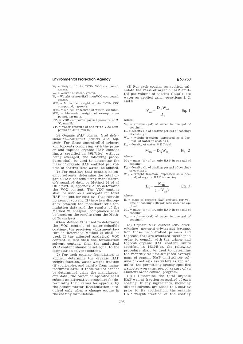
203
Environmental Protection Agency § 63.750
Wi = Weight of the ‘‘i’’th VOC compound,
grams.
Ww = Weight of water, grams.
We = Weight of non-HAP, nonVOC compound,
grams.
MWi = Molecular weight of the ‘‘i’’th VOC
compound, g/g-mole.
MWw = Molecular weight of water, g/g-mole.
MWe = Molecular weight of exempt com-
pound, g/g-mole.
PPc = VOC composite partial pressure at 20
°C, mm Hg.
VPi = Vapor pressure of the ‘‘i’’th VOC com-
pound at 20 °C, mm Hg.
(c) Organic HAP content level deter-
mination—compliant primers and top-
coats. For those uncontrolled primers and topcoats complying with the prim-er and topcoat organic HAP content limits specified in § 63.745(c) without being averaged, the following proce-dures shall be used to determine the mass of organic HAP emitted per vol-ume of coating (less water) as applied.
(1) For coatings that contain no ex-empt solvents, determine the total or-ganic HAP content using manufactur-er’s supplied data or Method 24 of 40 CFR part 60, appendix A, to determine the VOC content. The VOC content shall be used as a surrogate for total HAP content for coatings that contain no exempt solvent. If there is a discrep-ancy between the manufacturer’s for-mulation data and the results of the Method 24 analysis, compliance shall be based on the results from the Meth-od 24 analysis.
When Method 24 is used to determine the VOC content of water-reducible coatings, the precision adjustment fac-tors in Reference Method 24 shall be used. If the adjusted analytical VOC content is less than the formulation solvent content, then the analytical VOC content should be set equal to the formulation solvent content.
(2) For each coating formulation as applied, determine the organic HAP weight fraction, water weight fraction (if applicable), and density from manu-facturer’s data. If these values cannot be determined using the manufactur-er’s data, the owner or operator shall submit an alternative procedure for de-termining their values for approval by the Administrator. Recalculation is re-quired only when a change occurs in the coating formulation.
(3) For each coating as applied, cal-culate the mass of organic HAP emit-ted per volume of coating (lb/gal) less water as applied using equations 1, 2, and 3:
VD W
DEqwi
ci wi
w
= . 1
where:
Vwi = volume (gal) of water in one gal of
coating i.
Dci = density (lb of coating per gal of coating)
of coating i.
Wwi = weight fraction (expressed as a dec-
imal) of water in coating i.
Dw = density of water, 8.33 lb/gal.
M D W EqHi ci Hi= . 2
where:
MHi = mass (lb) of organic HAP in one gal of
coating i.
Dci = density (lb of coating per gal of coating)
of coating i.
WHi = weight fraction (expressed as a dec-
imal) of organic HAP in coating i.
HM
VEqi
Hi
wi
=−( )
.1
3
where:
Hi = mass of organic HAP emitted per vol-
ume of coating i (lb/gal) less water as ap-
plied.
MHi = mass (lb) of organic HAP in one gal of
coating i.
Vwi = volume (gal) of water in one gal of
coating i.
(d) Organic HAP content level deter-
mination—averaged primers and topcoats.
For those uncontrolled primers and topcoats that are averaged together in order to comply with the primer and topcoat organic HAP content limits specified in § 63.745(c), the following procedure shall be used to determine the monthly volume-weighted average mass of organic HAP emitted per vol-ume of coating (less water) as applied, unless the permitting agency specifies a shorter averaging period as part of an ambient ozone control program.
(1)(i) Determine the total organic HAP weight fraction as applied of each coating. If any ingredients, including diluent solvent, are added to a coating prior to its application, the organic HAP weight fraction of the coating
VerDate Mar<15>2010 17:45 Sep 05, 2014 Jkt 232159 PO 00000 Frm 00213 Fmt 8010 Sfmt 8010 Q:\40\40V11.TXT 31
ER
01
SE
95
.00
4<
/GP
H>
ER
01
SE
95
.00
5<
/GP
H>
ER
01
SE
95
.00
6<
/GP
H>

204
40 CFR Ch. I (7–1–14 Edition) § 63.750
shall be determined at a time and loca-tion in the process after all ingredients have been added.
(ii) Determine the total organic HAP weight fraction of each coating as ap-plied each month.
(A) If no changes have been made to a coating, either as supplied or as ap-plied, or if a change has been made that has a minimal effect on the or-ganic HAP content of the coating, the value previously determined may con-tinue to be used until a change in for-mulation has been made by either the manufacturer or the user.
(B) If a change in formulation or a change in the ingredients added to the coating takes place, including the ratio of coating to diluent solvent, prior to its application, either of which results in a more than minimal effect on the organic HAP content of the coating, the total organic HAP weight fraction of the coating shall be redetermined.
(iii) Manufacturer’s formulation data may be used to determine the total or-ganic HAP content of each coating and any ingredients added to the coating prior to its application. If the total or-ganic HAP content cannot be deter-mined using the manufacturer’s data, the owner or operator shall submit an alternative procedure for determining the total organic HAP weight fraction for approval by the Administrator.
(2)(i) Determine the volume both in total gallons as applied and in total gallons (less water) as applied of each coating. If any ingredients, including diluent solvents, are added prior to its application, the volume of each coating shall be determined at a time and loca-tion in the process after all ingredients (including any diluent solvent) have been added.
(ii) Determine the volume of each coating (less water) as applied each month, unless the permitting agency specifies a shorter period as part of an ambient ozone control program.
(iii) The volume applied may be de-termined from company records.
(3)(i) Determine the density of each coating as applied. If any ingredients, including diluent solvent, are added to a coating prior to its application, the density of the coating shall be deter-mined at a time and location in the
process after all ingredients have been added.
(ii) Determine the density of each coating as applied each month, unless the permitting agency specifies a shorter period as part of an ambient ozone control program.
(A) If no changes have been made to a coating, either as supplied or as ap-plied, or if a change has been made that has a minimal effect on the den-sity of the coating, then the value pre-viously determined may continue to be used until a change in formulation has been made by either the manufacturer or the user.
(B) If a change in formulation or a change in the ingredients added to the coating takes place, including the ratio of coating to diluent solvent, prior to its application, either of which results in a more than minimal effect on the density of the coating, then the density of the coating shall be redetermined.
(iii) The density may be determined from company records, including man-ufacturer’s data sheets. If the density of the coating cannot be determined using the company’s records, including the manufacturer’s data, then the owner or operator shall submit an al-ternative procedure for determining the density for approval by the Admin-istrator.
(4) Calculate the total volume in gal-lons as applied (less water) by summing the individual volumes of each coating (less water) as applied, which were de-termined under paragraph (d)(2) of this section.
(5) Calculate the volume-weighted average mass of organic HAP in coat-ings emitted per unit volume (lb/gal) of coating (less water) as applied during each 30-day period using equation 4:
H
W D V
CEqa
Hi ci ci
i
n
lw
= =∑
1 4.
where:
Ha = volume-weighted average mass of or-ganic HAP emitted per unit volume of coating (lb/gal) (less water) as applied during each 30-day period for those coat-ings being averaged.
n=number of coatings being averaged.
VerDate Mar<15>2010 17:45 Sep 05, 2014 Jkt 232159 PO 00000 Frm 00214 Fmt 8010 Sfmt 8010 Q:\40\40V11.TXT 31
ER
01
SE
95
.00
7<
/GP
H>
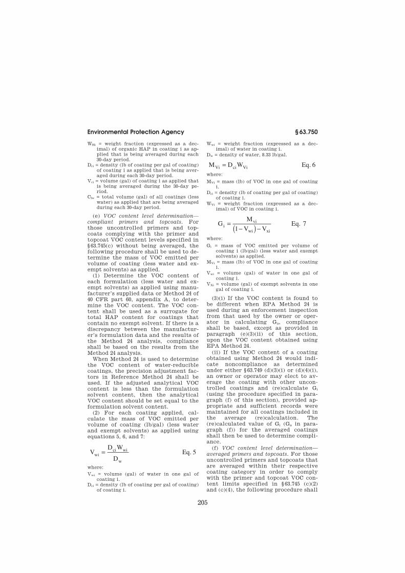
205
Environmental Protection Agency § 63.750
WHi = weight fraction (expressed as a dec-imal) of organic HAP in coating i as ap-plied that is being averaged during each 30-day period.
Dci = density (lb of coating per gal of coating) of coating i as applied that is being aver-aged during each 30-day period.
Vci = volume (gal) of coating i as applied that is being averaged during the 30-day pe-riod.
Clw = total volume (gal) of all coatings (less water) as applied that are being averaged during each 30-day period.
(e) VOC content level determination—
compliant primers and topcoats. For those uncontrolled primers and top-coats complying with the primer and topcoat VOC content levels specified in § 63.745(c) without being averaged, the following procedure shall be used to de-termine the mass of VOC emitted per volume of coating (less water and ex-empt solvents) as applied.
(1) Determine the VOC content of each formulation (less water and ex-empt solvents) as applied using manu-facturer’s supplied data or Method 24 of 40 CFR part 60, appendix A, to deter-mine the VOC content. The VOC con-tent shall be used as a surrogate for total HAP content for coatings that contain no exempt solvent. If there is a discrepancy between the manufactur-er’s formulation data and the results of the Method 24 analysis, compliance shall be based on the results from the Method 24 analysis.
When Method 24 is used to determine the VOC content of water-reducible coatings, the precision adjustment fac-tors in Reference Method 24 shall be used. If the adjusted analytical VOC content is less than the formulation solvent content, then the analytical VOC content should be set equal to the formulation solvent content.
(2) For each coating applied, cal-culate the mass of VOC emitted per volume of coating (lb/gal) (less water and exempt solvents) as applied using equations 5, 6, and 7:
VD W
DEqwi
ci wi
w
= . 5
where:
Vwi = volume (gal) of water in one gal of coating i.
Dci = density (lb of coating per gal of coating) of coating i.
Wwi = weight fraction (expressed as a dec-imal) of water in coating i.
Dw = density of water, 8.33 lb/gal.
M D W EqVi ci Vi= . 6
where:
MVi = mass (lb) of VOC in one gal of coating i.
Dci = density (lb of coating per gal of coating) of coating i.
WVi = weight fraction (expressed as a dec-imal) of VOC in coating i.
GM
V VEqi
vi
wi xi
=−( ) −1
. 7
where:
Gi = mass of VOC emitted per volume of coating i (lb/gal) (less water and exempt solvents) as applied.
MVi = mass (lb) of VOC in one gal of coating i.
Vwi = volume (gal) of water in one gal of coating i.
VXi = volume (gal) of exempt solvents in one gal of coating i.
(3)(i) If the VOC content is found to be different when EPA Method 24 is used during an enforcement inspection from that used by the owner or oper-ator in calculating Ga, compliance shall be based, except as provided in paragraph (e)(3)(ii) of this section, upon the VOC content obtained using EPA Method 24.
(ii) If the VOC content of a coating obtained using Method 24 would indi-cate noncompliance as determined under either § 63.749 (d)(3)(i) or (d)(4)(i), an owner or operator may elect to av-erage the coating with other uncon-trolled coatings and (re)calculate Gi (using the procedure specified in para-graph (f) of this section), provided ap-propriate and sufficient records were maintained for all coatings included in the average (re)calculation. The (re)calculated value of Gi (Ga in para-graph (f)) for the averaged coatings shall then be used to determine compli-ance.
(f) VOC content level determination—
averaged primers and topcoats. For those uncontrolled primers and topcoats that are averaged within their respective coating category in order to comply with the primer and topcoat VOC con-tent limits specified in § 63.745 (c)(2) and (c)(4), the following procedure shall
VerDate Mar<15>2010 17:45 Sep 05, 2014 Jkt 232159 PO 00000 Frm 00215 Fmt 8010 Sfmt 8010 Q:\40\40V11.TXT 31
ER
01
SE
95
.00
8<
/GP
H>
ER
01
SE
95
.00
9<
/GP
H>
ER
27
MR
98
.00
2<
/GP
H>
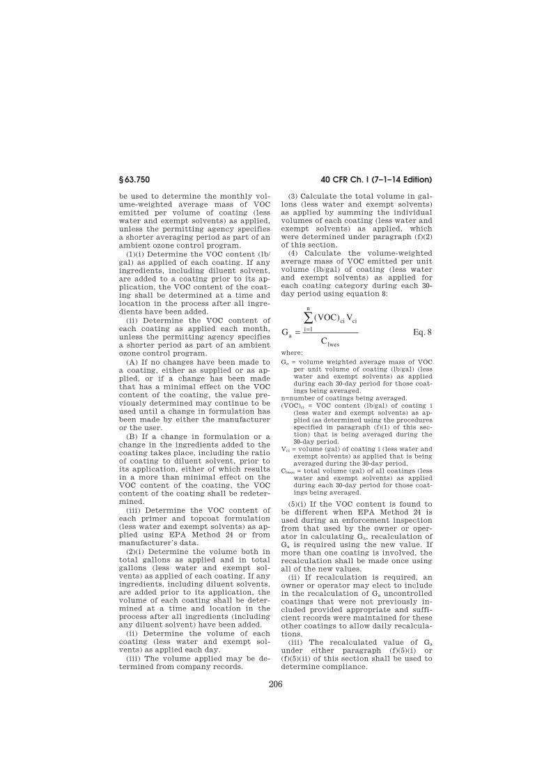
206
40 CFR Ch. I (7–1–14 Edition) § 63.750
be used to determine the monthly vol-ume-weighted average mass of VOC emitted per volume of coating (less water and exempt solvents) as applied, unless the permitting agency specifies a shorter averaging period as part of an ambient ozone control program.
(1)(i) Determine the VOC content (lb/ gal) as applied of each coating. If any ingredients, including diluent solvent, are added to a coating prior to its ap-plication, the VOC content of the coat-ing shall be determined at a time and location in the process after all ingre-dients have been added.
(ii) Determine the VOC content of each coating as applied each month, unless the permitting agency specifies a shorter period as part of an ambient ozone control program.
(A) If no changes have been made to a coating, either as supplied or as ap-plied, or if a change has been made that has a minimal effect on the VOC content of the coating, the value pre-viously determined may continue to be used until a change in formulation has been made by either the manufacturer or the user.
(B) If a change in formulation or a change in the ingredients added to the coating takes place, including the ratio of coating to diluent solvent, prior to its application, either of which results in a more than minimal effect on the VOC content of the coating, the VOC content of the coating shall be redeter-mined.
(iii) Determine the VOC content of each primer and topcoat formulation (less water and exempt solvents) as ap-plied using EPA Method 24 or from manufacturer’s data.
(2)(i) Determine the volume both in total gallons as applied and in total gallons (less water and exempt sol-vents) as applied of each coating. If any ingredients, including diluent solvents, are added prior to its application, the volume of each coating shall be deter-mined at a time and location in the process after all ingredients (including any diluent solvent) have been added.
(ii) Determine the volume of each coating (less water and exempt sol-vents) as applied each day.
(iii) The volume applied may be de-termined from company records.
(3) Calculate the total volume in gal-lons (less water and exempt solvents) as applied by summing the individual volumes of each coating (less water and exempt solvents) as applied, which were determined under paragraph (f)(2) of this section.
(4) Calculate the volume-weighted average mass of VOC emitted per unit volume (lb/gal) of coating (less water and exempt solvents) as applied for each coating category during each 30- day period using equation 8:
G
VOC V
CEqa
ci ci
i
n
lwes
= =∑ ( )
.1 8
where:
Ga = volume weighted average mass of VOC per unit volume of coating (lb/gal) (less water and exempt solvents) as applied during each 30-day period for those coat-ings being averaged.
n=number of coatings being averaged.
(VOC)ci = VOC content (lb/gal) of coating i (less water and exempt solvents) as ap-plied (as determined using the procedures specified in paragraph (f)(1) of this sec-tion) that is being averaged during the 30-day period.
Vci = volume (gal) of coating i (less water and exempt solvents) as applied that is being averaged during the 30-day period.
Clwes = total volume (gal) of all coatings (less water and exempt solvents) as applied during each 30-day period for those coat-ings being averaged.
(5)(i) If the VOC content is found to be different when EPA Method 24 is used during an enforcement inspection from that used by the owner or oper-ator in calculating Ga, recalculation of Ga is required using the new value. If more than one coating is involved, the recalculation shall be made once using all of the new values.
(ii) If recalculation is required, an owner or operator may elect to include in the recalculation of Ga uncontrolled coatings that were not previously in-cluded provided appropriate and suffi-cient records were maintained for these other coatings to allow daily recalcula-tions.
(iii) The recalculated value of Ga under either paragraph (f)(5)(i) or (f)(5)(ii) of this section shall be used to determine compliance.
VerDate Mar<15>2010 17:45 Sep 05, 2014 Jkt 232159 PO 00000 Frm 00216 Fmt 8010 Sfmt 8010 Q:\40\40V11.TXT 31
ER
01
SE
95
.01
1<
/GP
H>

207
Environmental Protection Agency § 63.750
(g) Overall VOC and/or organic HAP
control efficiency—carbon adsorber. Each owner or operator subject to the re-quirements of § 63.745(d), § 63.746(c), or § 63.747(d) shall demonstrate initial compliance with the requirements of this subpart by following the proce-dures of paragraph (g)(1), (2), (3), (4), or (5) as applicable and paragraphs (6), (7), and (8) of this section. When an initial compliance demonstration is required by this subpart, the procedures in para-graphs (g)(9) through (g)(14) of this sec-tion shall be used in determining ini-tial compliance with the provisions of this subpart.
(1) To demonstrate initial and con-tinuous compliance with § 63.745(d), § 63.746(c), or § 63.747(d) when emissions are controlled by a dedicated solvent recovery device, each owner or oper-ator of the affected operation may per-form a liquid-liquid HAP or VOC mate-rial balance over rolling 7- to 30-day pe-riods in lieu of demonstrating compli-ance through the methods in paragraph (g)(2), (g)(3), or (g)(4) of this section. Results of the material balance cal-culations performed to demonstrate initial compliance shall be submitted to the Administrator with the notifica-tion of compliance status required by § 63.9(h) and by § 63.753 (c)(1)(iv), (d)(3)(i), and (e)(3). When dem-onstrating compliance by this proce-dure, § 63.7(e)(3) of subpart A does not apply. The amount of liquid HAP or VOC applied and recovered shall be de-termined as discussed in paragraph (g)(1)(iii) of this section. The overall HAP or VOC emission reduction (R) is calculated using equation 9:
RM
W RS
Eqr
oi ci i
i
n=
−×
=∑ M[ ]
.
1
100 9
(i) The value of RSi is zero unless the owner or operator submits the fol-lowing information to the Adminis-trator for approval of a measured RSi value that is greater than zero:
(A) Measurement techniques; and
(B) Documentation that the meas-ured value of RSi exceeds zero.
(ii) The measurement techniques of paragraph (g)(1)(i)(A) of this section shall be submitted to the Adminis-
trator for approval with the notifica-tion of performance test required under § 63.7(b).
(iii) Each owner or operator dem-onstrating compliance by the test method described in paragraph (g)(1) of this section shall:
(A) Measure the amount of coating or stripper as applied;
(B) Determine the VOC or HAP con-tent of all coating and stripper applied using the test method specified in § 63.750(c) (1) through (3) or (e) (1) and (2) of this section;
(C) Install, calibrate, maintain, and operate, according to the manufactur-er’s specifications, a device that indi-cates the amount of HAP or VOC re-covered by the solvent recovery device over rolling 7- to 30-day periods; the de-vice shall be certified by the manufac-turer to be accurate to within ±2.0 per-cent, and this certification shall be kept on record;
(D) Measure the amount of HAP or VOC recovered; and
(E) Calculate the overall HAP or VOC emission reduction (R) for rolling 7- to 30-day periods using equation 9.
(F) Compliance is demonstrated if the value of R is equal to or greater than the overall HAP control effi-ciencies required by § 63.745(d), § 63.746(c), or § 63.747(d).
(2) To demonstrate initial compli-ance with § 63.745(d), § 63.746(c), or § 63.747(d) when affected HAP emission points are controlled by an emission control device other than a fixed-bed carbon adsorption system with indi-vidual exhaust stacks for each carbon adsorber vessel, each owner or operator of an affected source shall perform a gaseous emission test using the fol-lowing procedures.
(i) Construct the overall HAP emis-sion reduction system so that all volu-metric flow rates and total HAP or VOC emissions can be accurately deter-mined by the applicable test methods and procedures specified in § 63.750(g) (9) through (14).
(ii) Determine capture efficiency from the HAP emission points by cap-turing, venting, and measuring all HAP emissions from the HAP emission points. During a performance test, the owner or operator of affected HAP emission points located in an area with
VerDate Mar<15>2010 17:45 Sep 05, 2014 Jkt 232159 PO 00000 Frm 00217 Fmt 8010 Sfmt 8010 Q:\40\40V11.TXT 31
ER
01
SE
95
.01
2<
/GP
H>

208
40 CFR Ch. I (7–1–14 Edition) § 63.750
other gaseous emission sources not af-fected by this subpart shall isolate the affected HAP emission points from all other gaseous emission points by one of the following methods:
(A) Build a temporary total enclosure around the affected HAP emission point(s); or
(B) Shut down all gaseous emission points not affected by this subpart and continue to exhaust fugitive emissions from the affected HAP emission points through any building ventilation sys-tem and other room exhausts such as drying ovens. All ventilation air must be vented through stacks suitable for testing.
(iii) Operate the emission control de-vice with all affected HAP emission points connected and operating.
(iv) Determine the efficiency (E) of the control device using equation 10:
(v) Determine the efficiency (F) of the capture system using equation 11:
E Eq
F Eq
bi bi aj aj
j
P
i
n
bi bi
i
n
di di
i
n
di di
i
n
fk fk
k
P
=
−
=+
==
=
=
= =
∑∑
∑
∑
∑ ∑
Q C Q C
Q C
Q C
Q C Q C
11
1
1
1 1
10
11
.
.
(vi) For each HAP emission point subject to § 63.745(d), § 63.746(c), or § 63.747(d), compliance is demonstrated if the product of (E) × (F) is equal to or greater than the overall HAP control efficiencies required under § 63.745(d), § 63.746(c), or § 63.747(d).
(3) To demonstrate compliance with § 63.745(d), § 63.746(c), or § 63.747(d) when affected HAP emission points are con-trolled by a fixed-bed carbon adsorp-tion system with individual exhaust stacks for each carbon adsorber vessel, each owner or operator of an affected source shall perform a gaseous emis-sion test using the following proce-dures:
(i) Construct the overall HAP emis-sion reduction system so that each vol-umetric flow rate and the total HAP emissions can be accurately deter-mined by the applicable test methods and procedures specified in § 63.750(g) (9) through (14);
(ii) Assure that all HAP emissions from the affected HAP emission point(s) are segregated from gaseous emission points not affected by this subpart and that the emissions can be captured for measurement, as de-scribed in paragraphs (g)(2)(ii) (A) and (B) of this section;
(iii) Operate the emission control de-vice with all affected HAP emission points connected and operating;
(iv) Determine the efficiency (Hv) of each individual carbon adsorber vessel (v) using equation 12:
HQ Q
QEqv
gv gv hv hv
gv gv
=− C C
C.12
(v) Determine the efficiency of the carbon adsorption system (Hsys) by computing the average efficiency of the individual carbon adsorber vessels as weighted by the volumetric flow rate (Qhv) of each individual carbon adsorber vessel (v) using equation 13:
H Eqsys
v hv
v
q
hv
v
q= =
=
∑
∑
H Q
Q
1
1
13.
(vi) Determine the efficiency (F) of the capture system using equation 11.
(vii) For each HAP emission point subject to § 63.745(d), § 63.746(c), or § 63.747(d), compliance is demonstrated if the product of (Hsys) × (F) is equal to or greater than the overall HAP con-trol efficiency required by § 63.745(d), § 63.746(c), or § 63.747(d).
(4) An alternative method of dem-onstrating compliance with § 63.745(d), § 63.746(c), or § 63.747(d) is the installa-tion of a total enclosure around the af-fected HAP emission point(s) and the ventilation of all HAP emissions from the total enclosure to a control device with the efficiency specified in para-graph (g)(4)(iii) of this section. If this
VerDate Mar<15>2010 17:45 Sep 05, 2014 Jkt 232159 PO 00000 Frm 00218 Fmt 8010 Sfmt 8010 Q:\40\40V11.TXT 31
ER
01
SE
95
.01
3<
/GP
H>
ER
01
SE
95
.01
4<
/GP
H>
ER
01
SE
95
.01
5<
/GP
H>

209
Environmental Protection Agency § 63.750
method is selected, the compliance test methods described in paragraphs (g)(1), (g)(2), and (g)(3) of this section are not required. Instead, each owner or oper-ator of an affected source shall:
(i) Demonstrate that a total enclo-sure is installed. An enclosure that meets the requirements in paragraphs (g)(4)(i) (A) through (D) of this section shall be considered a total enclosure. The owner or operator of an enclosure that does not meet these requirements may apply to the Administrator for ap-proval of the enclosure as a total enclo-sure on a case-by-case basis. The enclo-sure shall be considered a total enclo-sure if it is demonstrated to the satis-faction of the Administrator that all HAP emissions from the affected HAP emission point(s) are contained and vented to the control device. The re-quirements for automatic approval are as follows:
(A) The total area of all natural draft openings shall not exceed 5% of the total surface area of the total enclo-sure’s walls, floor, and ceiling;
(B) All sources of emissions within the enclosure shall be a minimum of four equivalent diameters away from each natural draft opening;
(C) The average inward face velocity (FV) across all natural draft openings shall be a minimum of 3,600 meters per hour as determined by the following procedures:
(1) All forced makeup air ducts and all exhaust ducts are constructed so that the volumetric flow rate in each can be accurately determined by the test methods and procedures specified in § 63.750(g) (10) and (11); volumetric flow rates shall be calculated without the adjustment normally made for moisture content; and
(2) Determine FV by equation 14:
FV
Q Q
A
Eq
out j in i
i
p
j
n
k
k
q=
−==
=
∑∑
∑11
1
14.
(D) The air passing through all nat-ural draft openings shall flow into the enclosure continuously. If FV is less than or equal to 9,000 meters per hour, the continuous inward flow of air shall
be verified by continuous observation using smoke tubes, streamers, tracer gases, or other means approved by the Administrator over the period that the volumetric flow rate tests required to determine FV are carried out. If FV is greater than 9,000 meters per hour, the direction of airflow through the nat-ural draft openings shall be presumed to be inward at all times without verification.
(ii) Determine the control device effi-ciency using equation 10 or equations 12 and 13, as applicable, and the test methods and procedures specified in § 63.750(g) (9) through (14).
(iii) Compliance shall be achieved if the installation of a total enclosure is demonstrated and the value of E deter-mined from equation 10 (or the value of Hsys determined from equations 12 and 13, as applicable) is equal to or greater than the overall HAP control effi-ciencies required under § 63.745(d), § 63.746(c), or § 63.747(d).
(5) When nonregenerative carbon adsorbers are used to comply with § 63.745(d), § 63.746(c), or § 63.747(d), the owner or operator may conduct a de-sign evaluation to demonstrate initial compliance in lieu of following the compliance test procedures of para-graphs (g)(1), (2), (3), and (4) of this sec-tion. The design evaluation shall con-sider the vent stream composition, component concentrations, flow rate, relative humidity, and temperature, and shall establish the design exhaust vent stream organic compound con-centration level, capacity of the carbon bed, type and working capacity of acti-vated carbon used for the carbon bed, and design carbon replacement interval based on the total carbon working ca-pacity of the control device and the emission point operating schedule.
(6)(i) To demonstrate initial compli-ance with § 63.745(d), § 63.746(c), or § 63.747(d) when hard piping or duct-work is used to direct VOC and HAP emissions from a VOC and HAP source to the control device, each owner or op-erator shall demonstrate upon inspec-tion that the criteria of paragraph (g)(6)(i)(A) and paragraph (g)(6)(i) (B) or (C) of this section VR/FD are met.
(A) The equipment shall be vented to a control device.
VerDate Mar<15>2010 17:45 Sep 05, 2014 Jkt 232159 PO 00000 Frm 00219 Fmt 8010 Sfmt 8010 Q:\40\40V11.TXT 31
ER
01
SE
95
.01
6<
/GP
H>

210
40 CFR Ch. I (7–1–14 Edition) § 63.750
(B) The control device efficiency (E or Hsys, as applicable) determined using equation 10 or equations 12 and 13, re-spectively, and the test methods and procedures specified in § 63.750(g) (9) through (14), shall be equal to or great-er than the overall HAP control effi-ciency required by § 63.745(d), § 63.746(c), or § 63.747(d).
(C) When a nonregenerative carbon adsorber is used, the ductwork from the affected emission point(s) shall be vented to the control device and the carbon adsorber shall be demonstrated, through the procedures of § 63.750(g) (1), (2), (3), (4), or (5), to meet the require-ments of § 63.745(d), § 63.746(c), or § 63.747(d).
(7) Startups and shutdowns are nor-mal operation for this source category. Emissions from these activities are to be included when determining if the standards specified in § 63.745(d), § 63.746(c), or § 63.747(d) are being at-tained.
(8) An owner or operator who uses compliance techniques other than those specified in this subpart shall submit a description of those compli-ance procedures, subject to the Admin-istrator’s approval, in accordance with § 63.7(f) of subpart A.
(9) Either EPA Method 18 or EPA Method 25A of appendix A of part 60, as appropriate to the conditions at the site, shall be used to determine VOC and HAP concentration of air exhaust streams as required by § 63.750(g) (1) through (6). The owner or operator shall submit notice of the intended test method to the Administrator for ap-proval along with the notification of the performance test required under § 63.7(b). Method selection shall be based on consideration of the diversity of organic species present and their total concentration and on consider-ation of the potential presence of inter-fering gases. Except as indicated in paragraphs (g)(9) (i) and (ii) of this sec-tion, the test shall consist of three sep-arate runs, each lasting a minimum of 30 minutes.
(i) When either EPA Method 18 or EPA Method 25A is to be used in the determination of the efficiency of a fixed-bed carbon adsorption system with a common exhaust stack for all the individual carbon adsorber vessels
pursuant to paragraph (g) (2) or (4) of this section, the test shall consist of three separate runs, each coinciding with one or more complete sequences through the adsorption cycles of all of the individual carbon adsorber vessels.
(ii) When either EPA Method 18 or EPA Method 25A is to be used in the determination of the efficiency of a fixed-bed carbon adsorption system with individual exhaust stacks for each carbon adsorber vessel pursuant to § 63.750(g) (3) or (4), each carbon adsorber vessel shall be tested individ-ually. The test for each carbon adsorber vessel shall consist of three separate runs. Each run shall coincide with one or more complete adsorption cycles.
(10) EPA Method 1 or 1A of appendix A of part 60 is used for sample and ve-locity traverses.
(11) EPA Method 2, 2A, 2C, or 2D of appendix A of part 60 is used for veloc-ity and volumetric flow rates.
(12) EPA Method 3 of appendix A of part 60 is used for gas analysis.
(13) EPA Method 4 of appendix A of part 60 is used for stack gas moisture.
(14) EPA Methods 2, 2A, 2C, 2D, 3, and 4 shall be performed, as applicable, at least twice during each test period.
(h) Overall VOC and/or organic HAP
control efficiency—control devices other
than carbon adsorbers. Calculate the overall control efficiency of a control system with a control device other than a carbon adsorber using the fol-lowing procedure.
(1) Calculate the overall control effi-ciency using equation 15:
E R F Eqk k k= . 15
where:
Ek = overall VOC and/or organic HAP control efficiency (expressed as a decimal) of control system k.
Rk = destruction or removal efficiency (ex-pressed as a decimal) of total organic compounds or total organic HAP for con-trol device k as determined under para-graph (h)(2) of this section.
Fk = capture efficiency (expressed as a dec-imal) of capture system k as determined under paragraph (h)(3) of this section.
(2) The organic HAP destruction or removal efficiency Rk of a control de-vice other than a carbon adsorber shall
VerDate Mar<15>2010 17:45 Sep 05, 2014 Jkt 232159 PO 00000 Frm 00220 Fmt 8010 Sfmt 8010 Q:\40\40V11.TXT 31
ER
01
SE
95
.01
7<
/GP
H>

211
Environmental Protection Agency § 63.750
be determined using the procedures de-scribed below. The destruction effi-ciency may be measured as either total organic HAP or as TOC minus methane and ethane according to these proce-dures.
(i) Use Method 1 or 1A of 40 CFR part 60, appendix A, as appropriate, to select the sampling sites.
(ii) Determine the gas volumetric flow rate using Method 2, 2A, 2C, or 2D of 40 CFR part 60, appendix A, as appro-priate.
(iii) Use Method 18 of 40 CFR part 60, appendix A, to measure either TOC minus methane and ethane or total or-ganic HAP. Alternatively, any other method or data that have been vali-dated according to the applicable pro-cedures in Method 301 of this part may be used.
(iv) Use the following procedure to calculate the destruction or removal efficiency:
(A) The destruction or removal effi-ciency test shall consist of three runs. The minimum sampling time for each run shall be 1 hour in which either an integrated sample or a minimum of four grab samples shall be taken. If grab sampling is used, the samples shall be taken at approximately equal intervals in time such as 15-minute in-tervals during the run.
(B) Calculate the mass rate of either TOC (minus methane and ethane) or total organic HAP (Ei, Eo using equa-tions 16 and 17:
E K C M Eq
E K C M Eq
i ij ij
j
n
i
o oj oj
j
n
o
=
=
=
=
∑
∑
2
1
2
1
16
17
Q
Q
.
.
where:
Ei, Eo = mass rate of TOC (minus methane and ethane) or total organic HAP at the inlet and outlet of the control device, re-spectively, dry basis, kg/hr.
K2 = constant, 2.494×10¥6 (parts per mil-lion)¥1 (gram-mole per standard cubic meter) (kilogram/gram) (minute/hour), where standard temperature for (gram- mole per standard cubic meter) is 20 °C.
n=number of sample components in the gas stream.
Cij, Coj = concentration of sample component j of the gas stream at the inlet and outlet of the control device, respectively, dry basis, parts per million by volume.
Mij, Moj = molecular weight of sample compo-nent j of the gas stream at the inlet and outlet of the control device, respectively, gram/gram-mole.
Qi, Qo = flow rate of gas stream at the inlet and outlet of the control device, respec-tively, dry standard cubic meter per minute.
(1) Where the mass rate of TOC is being calculated, all organic com-pounds (minus methane and ethane) measured by EPA Method 18 shall be summed using equation 16 in paragraph (h)(2)(iv)(B) of this section.
(2) Where the mass rate of total or-ganic HAP is being calculated, only the organic HAP species shall be summed using equation 17 in paragraph (h)(2)(iv)(B) of this section. The list of organic HAP is provided in § 63.104 of subpart F of this part.
(C) Calculate the destruction or re-moval efficiency for TOC (minus meth-ane and ethane) or total organic HAP using equation 18:
RE E
EEqi o
i
=−
×100 18.
where:
R=destruction or removal efficiency of con-trol device, percent.
Ei = mass rate of TOC (minus methane and ethane) or total organic HAP at the inlet to the control device as calculated under paragraph (h)(2)(iv)(B) of this section, kg TOC per hour or kg organic HAP per hour.
Eo = mass rate of TOC (minus methane and ethane) or total organic HAP at the out-let of the control device, as calculated under paragraph (h)(2)(iv)(B) of this sec-tion, kg TOC per hour or kg organic HAP per hour.
(3) Determine the capture efficiency Fk of each capture system to which or-ganic HAP and VOC emissions from coating operations are vented. The cap-ture efficiency value shall be deter-mined using Procedure T—Criteria for and Verification of a Permanent or Temporary Total Enclosure as found in appendix B to § 52.741 of part 52 of this chapter for total enclosures, and the capture efficiency protocol specified in
VerDate Mar<15>2010 17:45 Sep 05, 2014 Jkt 232159 PO 00000 Frm 00221 Fmt 8010 Sfmt 8010 Q:\40\40V11.TXT 31
ER
01
SE
95
.01
8<
/GP
H>
ER
01
SE
95
.01
9<
/GP
H>

212
40 CFR Ch. I (7–1–14 Edition) § 63.750
§ 52.741(a)(4)(iii) of part 52 of this chap-ter for all other enclosures.
(i)(1) Alternative application method—
primers and topcoats. Each owner or op-erator seeking to use an alternative ap-plication method (as allowed in § 63.745(f)(1)(ix)) in complying with the standards for primers and topcoats shall use the procedures specified in paragraphs (i)(2)(i) and (i)(2)(ii) or (i)(2)(iii) of this section to determine the organic HAP and VOC emission lev-els of the alternative application tech-nique as compared to either HVLP or electrostatic spray application meth-ods.
(2)(i) For the process or processes for which the alternative application method is to be used, the total organic HAP and VOC emissions shall be deter-mined for an initial 30-day period, the period of time required to apply coat-ing to five completely assembled air-craft, or a time period approved by the permitting agency. During this initial period, only HVLP or electrostatic spray application methods shall be used. The emissions shall be deter-mined based on the volumes, organic HAP contents (less water), and VOC contents (less water and exempt sol-vents) of the coatings as applied.
(ii) Upon implementation of the al-ternative application method, use the alternative application method in pro-duction on actual production parts or assemblies for a period of time suffi-cient to coat an equivalent amount of parts and assemblies with coatings identical to those used in the initial 30- day period. The actual organic HAP and VOC emissions shall be calculated for this post-implementation period.
(iii) Test the proposed application method against either HVLP or elec-trostatic spray application methods in a laboratory or pilot production area, using parts and coatings representative of the process(es) where the alternative method is to be used. The laboratory test will use the same part configura-tion(s) and the same number of parts for both the proposed method and the HVLP or electrostatic spray applica-tion methods.
(iv) Whenever the approach in either paragraph (i)(2)(ii) or (i)(2)(iii) of this section is used, the owner or operator shall calculate both the organic HAP
and VOC emission reduction using equation:
PE E
EEqb a
b
=−
×100 19.
where:
P=organic HAP or VOC emission reduction, percent.
Eb = organic HAP or VOC emissions, in pounds, before the alternative applica-tion technique was implemented, as de-termined under paragraph (i)(2)(i) of this section.
Ea = organic HAP of VOC emissions, in pounds, after the alternative application technique was implemented, as deter-mined under paragraph (i)(2)(ii) of this section.
(3) Each owner or operator seeking to demonstrate that an alternative appli-cation method achieves emission re-ductions equivalent to HVLP or elec-trostatic spray application methods shall comply with the following:
(i) Each coating shall be applied such that the dried film thickness is within the range specified by the applicable specification(s) for the aerospace vehi-cle or component being coated.
(ii) If no such dried film thickness specification(s) exists, the owner or op-erator shall ensure that the dried film thickness applied during the initial 30- day period is equivalent to the dried film thickness applied during the alter-native application method test period for similar aerospace vehicles or com-ponents.
(iii) Failure to comply with these dried film thickness requirements shall invalidate the test results obtained under paragraph (i)(2)(i) of this section.
(j) Spot stripping and decal removal.
Each owner or operator seeking to comply with § 63.746(b)(3) shall deter-mine the volume of organic HAP-con-taining chemical strippers or alter-natively the weight of organic HAP used per aircraft using the procedure specified in paragraphs (j)(1) through (j)(3) of this section.
(1) For each chemical stripper used for spot stripping and decal removal, determine for each annual period the total volume as applied or the total weight of organic HAP using the proce-dure specified in paragraph (d)(2) of this section.
VerDate Mar<15>2010 17:45 Sep 05, 2014 Jkt 232159 PO 00000 Frm 00222 Fmt 8010 Sfmt 8010 Q:\40\40V11.TXT 31
ER
01
SE
98
.00
1<
/GP
H>
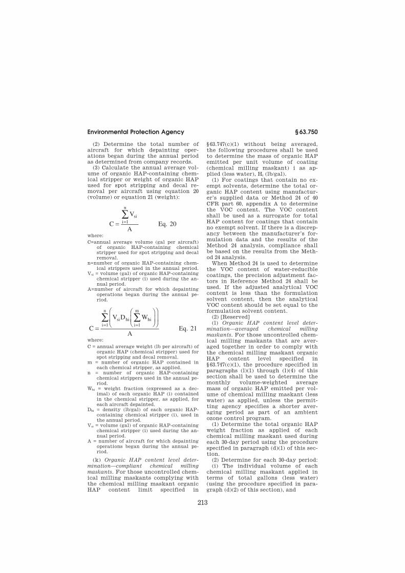
213
Environmental Protection Agency § 63.750
(2) Determine the total number of aircraft for which depainting oper-ations began during the annual period as determined from company records.
(3) Calculate the annual average vol-ume of organic HAP-containing chem-ical stripper or weight of organic HAP used for spot stripping and decal re-moval per aircraft using equation 20 (volume) or equation 21 (weight):
C
V
AEq.
si
i
n
= =∑
1 20
where:
C=annual average volume (gal per aircraft) of organic HAP-containing chemical stripper used for spot stripping and decal removal.
n=number of organic HAP-containing chem-ical strippers used in the annual period.
Vsi = volume (gal) of organic HAP-containing chemical stripper (i) used during the an-nual period.
A=number of aircraft for which depainting operations began during the annual pe-riod.
C
V D W
Eq
si hi hi
i
m
i
n
=
==∑∑
11
A 21.
where:
C = annual average weight (lb per aircraft) of organic HAP (chemical stripper) used for spot stripping and decal removal.
m = number of organic HAP contained in each chemical stripper, as applied.
n = number of organic HAP-containing chemical strippers used in the annual pe-riod.
Whi = weight fraction (expressed as a dec-imal) of each organic HAP (i) contained in the chemical stripper, as applied, for each aircraft depainted.
Dhi = density (lb/gal) of each organic HAP- containing chemical stripper (i), used in the annual period.
Vsi = volume (gal) of organic HAP-containing chemical stripper (i) used during the an-nual period.
A = number of aircraft for which depainting operations began during the annual pe-riod.
(k) Organic HAP content level deter-
mination—compliant chemical milling
maskants. For those uncontrolled chem-ical milling maskants complying with the chemical milling maskant organic HAP content limit specified in
§ 63.747(c)(1) without being averaged, the following procedures shall be used to determine the mass of organic HAP emitted per unit volume of coating (chemical milling maskant) i as ap-plied (less water), Hi (lb/gal).
(1) For coatings that contain no ex-empt solvents, determine the total or-ganic HAP content using manufactur-er’s supplied data or Method 24 of 40 CFR part 60, appendix A to determine the VOC content. The VOC content shall be used as a surrogate for total HAP content for coatings that contain no exempt solvent. If there is a discrep-ancy between the manufacturer’s for-mulation data and the results of the Method 24 analysis, compliance shall be based on the results from the Meth-od 24 analysis.
When Method 24 is used to determine the VOC content of water-reducible coatings, the precision adjustment fac-tors in Reference Method 24 shall be used. If the adjusted analytical VOC content is less than the formulation solvent content, then the analytical VOC content should be set equal to the formulation solvent content.
(2) [Reserved] (l) Organic HAP content level deter-
mination—averaged chemical milling
maskants. For those uncontrolled chem-ical milling maskants that are aver-aged together in order to comply with the chemical milling maskant organic HAP content level specified in § 63.747(c)(1), the procedure specified in paragraphs (l)(1) through (l)(4) of this section shall be used to determine the monthly volume-weighted average mass of organic HAP emitted per vol-ume of chemical milling maskant (less water) as applied, unless the permit-ting agency specifies a shorter aver-aging period as part of an ambient ozone control program.
(1) Determine the total organic HAP weight fraction as applied of each chemical milling maskant used during each 30-day period using the procedure specified in paragraph (d)(1) of this sec-tion.
(2) Determine for each 30-day period: (i) The individual volume of each
chemical milling maskant applied in terms of total gallons (less water) (using the procedure specified in para-graph (d)(2) of this section), and
VerDate Mar<15>2010 17:45 Sep 05, 2014 Jkt 232159 PO 00000 Frm 00223 Fmt 8010 Sfmt 8010 Q:\40\40V11.TXT 31
ER
27
MR
98
.00
4<
/GP
H>
ER
27
MR
98
.00
5<
/GP
H>

214
40 CFR Ch. I (7–1–14 Edition) § 63.750
(ii) The total volume in gallons of all chemical milling maskants (less water) as applied by summing the individual volumes of each chemical milling maskant as applied (less water).
(3) Determine the density of each chemical milling maskant as applied used during each 30-day period using the procedure specified in paragraph (d)(3) of this section.
(4) Calculate the volume-weighted average mass of organic HAP emitted per unit volume (lb/gal) of chemical milling maskant (less water) as applied for all chemical milling maskants dur-ing each 30-day period using equation 22:
H
W D V
Ma
Hi mi mi
i
n
lw
= =∑
1 Eq. 22
where:
Ha = volume-weighted mass of organic HAP emitted per unit volume of chemical milling maskants (lb/gal) (less water) as applied during each 30-day period for those chemical milling maskants being averaged.
n=number of chemical milling maskants being averaged.
WHi = weight fraction (expressed as a dec-imal) of organic HAP in chemical milling maskant i (less water) as applied during each 30-day period that is averaged.
Dmi = density (lb chemical milling maskant per gal coating) of chemical milling maskant i as applied during each 30-day period that is averaged.
Vmi = volume (gal) of chemical milling maskant i (less water) as applied during the 30-day period that is averaged.
Mlw = total volume (gal) of all chemical mill-ing maskants (less water) as applied dur-ing each 30-day period that is averaged.
(m) VOC content level determination—
compliant chemical milling maskants. For those uncontrolled chemical milling maskants complying with the chemical milling maskant VOC content limit specified in § 63.747(c)(2) without being averaged, the procedure specified in paragraphs (m)(1) and (m)(2) of this section shall be used to determine the mass of VOC emitted per volume of chemical milling maskant (less water and exempt solvents) as applied.
(1) Determine the mass of VOC emit-ted per unit volume of chemical mill-ing maskant (lb/gal) (less water and ex-
empt solvents) as applied, Gi, for each chemical milling maskant using the procedures specified in paragraphs (e)(1) and (e)(2) of this section.
(2)(i) If the VOC content is found to be different when EPA Method 24 is used during an enforcement inspection from that used by the owner or oper-ator in calculating Gi, compliance shall be based, except as provided in para-graph (m)(2)(ii) of this section, upon the VOC content obtained using EPA Method 24.
(ii) If the VOC content of a chemical milling maskant obtained using EPA Method 24 would indicate noncompli-ance as determined under § 63.749(h)(3)(i), an owner or operator may elect to average the chemical milling maskant with other uncon-trolled chemical milling maskants and (re)calculate Ga (using the procedure specified in paragraph (n) of this sec-tion), provided appropriate and suffi-cient records were maintained for all chemical milling maskants included in the average recalculation. The (re)calculated value of Ga for the aver-aged chemical milling maskants shall then be used to determine compliance.
(n) VOC content level determination—
averaged chemical milling maskants. For those uncontrolled chemical milling maskants that are averaged together in order to comply with the chemical milling maskant VOC content limit specified in § 63.747(c)(2), the procedure specified in paragraphs (n)(1) through (n)(4) of this section shall be used to determine the monthly volume-weight-ed average mass of VOC emitted per volume of chemical milling maskant (less water and exempt solvents) as ap-plied, unless the permitting agency specifies a shorter averaging period as part of an ambient ozone control pro-gram.
(1) Determine the VOC content of each chemical milling maskant (less water and exempt solvents) as applied used during each 30-day period using the procedure specified in paragraph (f)(1) of this section.
(2)(i) Determine the individual vol-ume of each chemical milling maskant applied in terms of total gallons (less water and exempt solvents) using the procedure specified in paragraph (f)(2) of this section, and
VerDate Mar<15>2010 17:45 Sep 05, 2014 Jkt 232159 PO 00000 Frm 00224 Fmt 8010 Sfmt 8010 Q:\40\40V11.TXT 31
ER
27
MR
98
.00
6<
/GP
H>

215
Environmental Protection Agency § 63.751
(ii) Calculate the total volume in gal-lons of all chemical milling maskants (less water and exempt solvents) as ap-plied by summing the individual vol-umes of each chemical milling maskant (less water and exempt sol-vents) as applied.
(3) Calculate the volume-weighted average mass of VOC emitted per unit volume (lb/gal) of chemical milling maskant (less water and exempt sol-vents) as applied during each 30-day pe-riod using equation 23:
G
VOC V
Ma
mi mi
i
n
lwes
= =∑ ( )
1 Eq. 23
where:
Ga = volume-weighted average mass of VOC per unit volume of chemical milling maskant (lb/gal) (less water and exempt solvents) as applied during each 30-day period for those chemical milling maskants that are averaged.
n=number of chemical milling maskants being averaged.
(VOC)mi = VOC content (lb/gal) of chemical milling maskant i (less water and exempt solvents) as applied during the 30-day pe-riod that is averaged.
Vmi = volume (gal) of chemical milling maskant i (less water and exempt sol-vents) as applied during the 30-day period that is averaged.
Mlwes = total volume (gal) of all chemical milling maskants (less water and exempt solvents) as applied during each 30-day period that is averaged.
(4)(i) If the VOC content is found to be different when EPA Method 24 is used during an enforcement inspection from that used by the owner or oper-ator in calculating Ga, recalculation of Ga is required using the new value. If more than one chemical milling maskant is involved, the recalculation shall be made once using all of the new values.
(ii) If recalculation is required, an owner or operator may elect to include in the recalculation of Ga uncontrolled chemical milling maskants that were not previously included provided appro-priate and sufficient records were maintained for these other chemical milling maskants to allow daily recal-culations.
(iii) The recalculated value of Ga under either paragraph (n)(4)(i) or
(n)(4)(ii) of this section shall be used to
determine compliance.
(o) Inorganic HAP emissions—dry par-
ticulate filter certification requirements.
Dry particulate filters used to comply
with § 63.745(g)(2) or § 63.746(b)(4) must
be certified by the filter manufacturer
or distributor, paint/depainting booth
supplier, and/or the facility owner or
operator using method 319 in appendix
A of this part, to meet or exceed the ef-
ficiency data points found in Tables 1
and 2, or 3 and 4 of § 63.745 for existing
or new sources respectively.
[60 FR 45956, Sept. 1, 1996, as amended at 63
FR 15021, Mar. 27, 1998; 63 FR 46534, Sept. 1,
1998; 65 FR 62215, Oct. 17, 2000; 79 FR 11284,
Feb. 27, 2014]
§ 63.751 Monitoring requirements.
(a) Enclosed spray gun cleaners. Each
owner or operator using an enclosed
spray gun cleaner under § 63.744(c)(1)
shall visually inspect the seals and all
other potential sources of leaks associ-
ated with each enclosed gun spray
cleaner system at least once per
month. Each inspection shall occur
while the system is in operation.
(b) Incinerators and carbon adsorbers—
initial compliance demonstrations. Each
owner or operator subject to the re-
quirements in this subpart must dem-
onstrate initial compliance with the
requirements of §§ 63.745(d), 63.746(c),
and 63.747(d) of this subpart. Each
owner or operator using a carbon
adsorber to comply with the require-
ments in this subpart shall comply
with the requirements specified in
paragraphs (b)(1) through (7) of this
section. Each owner or operator using
an incinerator to comply with the re-
quirements in this subpart shall com-
ply with the requirements specified in
paragraphs (b)(8) through (12) of this
section.
(1) Except as allowed by paragraph
(b)(2) or (b)(5) of this section, for each
control device used to control organic
HAP or VOC emissions, the owner or
operator shall fulfill the requirements
of paragraph (b)(1) (i) or (ii) of this sec-
tion.
VerDate Mar<15>2010 17:45 Sep 05, 2014 Jkt 232159 PO 00000 Frm 00225 Fmt 8010 Sfmt 8010 Q:\40\40V11.TXT 31
ER
27
MR
98
.00
7<
/GP
H>

216
40 CFR Ch. I (7–1–14 Edition) § 63.751
(i) The owner or operator shall estab-lish as a site-specific operating param-eter the outlet total HAP or VOC con-centration that demonstrates compli-ance with § 63.745(d), § 63.746(c), or § 63.747(d) as appropriate; or
(ii) The owner or operator shall es-tablish as the site-specific operating parameter the control device efficiency that demonstrates compliance with § 63.745(d), § 63.746(c), or § 63.747(d).
(iii) When a nonregenerative carbon adsorber is used to comply with § 63.745(d), § 63.746(c), or § 63.747(d), the site-specific operating parameter value may be established as part of the de-sign evaluation used to demonstrate initial compliance. Otherwise, the site- specific operating parameter value shall be established during the initial performance test conducted according to the procedures of § 63.750(g).
(2) For each nonregenerative carbon adsorber, in lieu of meeting the re-quirements of § 63.751(b)(1), the owner or operator may establish as the site- specific operating parameter the car-bon replacement time interval, as de-termined by the maximum design flow rate and organic concentration in the gas stream vented to the carbon ad-sorption system. The carbon replace-ment time interval shall be established either as part of the design evaluation to demonstrate initial compliance or during the initial performance test conducted according to the procedures in § 63.750(g) (1), (2), (3), or (4).
(3) Each owner or operator venting solvent HAP emissions from a source through a room, enclosure, or hood, to a control device to comply with § 63.745(d), § 63.746(c), or § 63.747(d) shall:
(i) Submit to the Administrator with the compliance status report required by § 63.9(h) of the General Provisions a plan that:
(A) Identifies the operating param-eter to be monitored to ensure that the capture efficiency measured during the initial compliance test is maintained;
(B) Discusses why this parameter is appropriate for demonstrating ongoing compliance; and
(C) Identifies the specific monitoring procedures;
(ii) Set the operating parameter value, or range of values, that dem-onstrate compliance with § 63.745(d),
§ 63.746(c), or § 63.747(d), as appropriate; and
(iii) Conduct monitoring in accord-ance with the plan submitted to the Administrator unless comments re-ceived from the Administrator require an alternate monitoring scheme.
(4) Owners or operators subject to § 63.751(b) (1), (2), or (3) shall calculate the site-specific operating parameter value, or range of values, as the arith-metic average of the maximum and/or minimum operating parameter values, as appropriate, that demonstrate com-pliance with § 63.745(d), § 63.746(c), or § 63.747(d) during the multiple test runs required by § 63.750 (g)(2) and (g)(1).
(5) For each solvent recovery device used to comply with § 63.745(d), § 63.746(c), or § 63.747(d), in lieu of meet-ing the requirements of paragraph (b)(1) of this section, the results of the material balance calculation conducted in accordance with § 63.750(g)(1) may serve as the site-specific operating pa-rameter that demonstrates compliance with § 63.745(d), § 63.746(c), or § 63.747(d).
(6) Continuous compliance monitoring.
Following the date on which the initial compliance demonstration is com-pleted, continuous compliance with § 63.745(d), § 63.746(c), or § 63.747(d) of this subpart shall be demonstrated as outlined in this paragraph.
(i) Each owner or operator of an af-fected source subject to § 63.745(d), § 63.746(c), or § 63.747(d) of this subpart shall monitor the applicable param-eters specified in paragraph (b)(6)(ii), (b)(6)(iii), or (b)(6)(iv) of this section depending on the type of control tech-nique used.
(ii) Compliance monitoring shall be subject to the following provisions:
(A) Except as allowed by paragraph (b)(6)(iii)(A)(2) of this section, all con-tinuous emission monitors shall com-ply with performance specification (PS) 8 or 9 in 40 CFR part 60, appendix B, as appropriate depending on whether VOC or HAP concentration is being measured. The requirements in appen-dix F of 40 CFR part 60 shall also be fol-lowed. In conducting the quarterly au-dits required by appendix F, owners or operators shall challenge the monitors with compounds representative of the gaseous emission stream being con-trolled.
VerDate Mar<15>2010 17:45 Sep 05, 2014 Jkt 232159 PO 00000 Frm 00226 Fmt 8010 Sfmt 8010 Q:\40\40V11.TXT 31

217
Environmental Protection Agency § 63.751
(B) If the effluent from multiple emission points are combined prior to being channeled to a common control device, the owner or operator is re-quired only to monitor the common control device, not each emission point.
(iii) Owners or operators complying with § 63.745(d), § 63.746(c), or § 63.747(d) through the use of a control device and establishing a site-specific operating parameter in accordance with para-graph (b)(1) of this section shall fulfill the requirements of paragraph (b)(6)(iii)(A) of this section and para-graph (b)(6)(iii)(B) or (C) of this sec-tion, as appropriate.
(A) The owner or operator shall in-stall, calibrate, operate, and maintain a continuous emission monitor.
(1) The continuous emission monitor shall be used to measure continuously the total HAP or VOC concentration at both the inlet and the outlet whenever HAP from coating and paint stripping operations are vented to the control device, or when continuous compliance is demonstrated through a percent effi-ciency calculation; or
(2) For owners or operators using a nonregenerative carbon adsorber, in lieu of using continuous emission mon-itors as specified in paragraph (b)(6)(iii)(A)(1) of this section, the owner or operator may use a portable monitoring device to monitor total HAP or VOC concentration at the inlet and outlet or the outlet of the carbon adsorber as appropriate.
(a) The monitoring device shall be calibrated, operated, and maintained in accordance with the manufacturer’s specifications.
(b) The monitoring device shall meet the requirements of part 60, appendix A, Method 21, sections 2, 3, 4.1, 4.2, and 4.4. The calibration gas shall either be representative of the compounds to be measured or shall be methane, and shall be at a concentration associated with 125% of the expected organic com-pound concentration level for the car-bon adsorber outlet vent.
(c) The probe inlet of the monitoring device shall be placed at approximately the center of the carbon adsorber out-let vent. The probe shall be held there for at least 5 minutes during which flow into the carbon adsorber is ex-
pected to occur. The maximum reading during that period shall be used as the measurement.
(B) If complying with § 63.745(d), § 63.746(c), or § 63.747(d) through the use of a carbon adsorption system with a common exhaust stack for all of the carbon vessels, the owner or operator shall not operate the control device at an average control efficiency less than that required by § 63.745(d), § 63.746(c), or § 63.747(d) for three consecutive ad-sorption cycles.
(C) If complying with § 63.745(d), § 63.746(c), or § 63.747(d) through the use of a carbon adsorption system with in-dividual exhaust stacks for each of the multiple carbon adsorber vessels, the owner or operator shall not operate any carbon adsorber vessel at an aver-age control efficiency less than that re-quired by § 63.745(d), § 63.746(c), or § 63.747(d) as calculated daily using a 7 to 30-day rolling average.
(D) If complying with § 63.745(d), § 63.746(c), or § 63.747(d) through the use of a nonregenerative carbon adsorber, in lieu of the requirements of para-graph (b)(6)(iii) (B) or (C) of this sec-tion, the owner or operator may mon-itor the VOC or HAP concentration of the adsorber exhaust daily, at intervals no greater than 20 percent of the design carbon replacement interval, which-ever is greater, or at a frequency as de-termined by the owner or operator and approved by the Administrator.
(iv) Owners or operators complying with § 63.745(d), § 63.746(c), or § 63.747(d) through the use of a nonregenerative carbon adsorber and establishing a site-specific operating parameter for the carbon replacement time interval in accordance with paragraph (b)(2) shall replace the carbon in the carbon adsorber system with fresh carbon at the predetermined time interval as de-termined in the design evaluation.
(v) Owners or operators complying with § 63.745(d), § 63.746(c), or § 63.747(d) by capturing emissions through a room, enclosure, or hood shall install, calibrate, operate, and maintain the in-strumentation necessary to measure continuously the site-specific oper-ating parameter established in accord-ance with paragraph (b)(3) of this sec-tion whenever VOC and HAP from coating and stripper operations are
VerDate Mar<15>2010 17:45 Sep 05, 2014 Jkt 232159 PO 00000 Frm 00227 Fmt 8010 Sfmt 8010 Q:\40\40V11.TXT 31

218
40 CFR Ch. I (7–1–14 Edition) § 63.751
vented through the capture device. The capture device shall not be operated at an average value greater than or less than (as appropriate) the operating pa-rameter value established in accord-ance with paragraph (b)(3) of this sec-tion for any 3-hour period.
(7) Owners or operators complying with paragraph (b)(4) or (b)(5) of this section shall calculate the site-specific operating parameter value as the arith-metic average of the minimum oper-ating parameter values that dem-onstrate compliance with § 63.745(d)and § 63.747(d) during the three test runs re-quired by § 63.750(h)(2)(iv).
(8) All temperature monitoring equipment shall be installed, cali-brated, maintained, and operated ac-cording to manufacturer’s specifica-tions. Every 3 months, facilities shall replace the temperature sensors or have the temperature sensors recali-brated. As an alternative, a facility may use a continuous emission moni-toring system (CEMS) to verify that there has been no change in the de-struction efficiency and effluent com-position of the incinerator.
(9) Where an incinerator other than a catalytic incinerator is used, a thermo-couple equipped with a continuous re-corder shall be installed and continu-ously operated in the firebox or in the ductwork immediately downstream of the firebox in a position before any substantial heat exchange occurs.
(10) Where a catalytic incinerator is used, thermocouples, each equipped with a continuous recorder, shall be in-stalled and continuously operated in the gas stream immediately before and after the catalyst bed.
(11) For each incinerator other than a catalytic incinerator, each owner or operator shall establish during each performance test during which compli-ance is demonstrated, including the initial performance test, the minimum combustion temperature as a site-spe-cific operating parameter. This min-imum combustion temperature shall be the operating parameter value that demonstrates compliance with §§ 63.745(d) and 63.747(d).
(12) For each catalytic incinerator, each owner or operator shall establish during each performance test during which compliance is demonstrated, in-
cluding the initial performance test, the minimum gas temperature up-stream of the catalyst bed and the min-imum gas temperature difference across the catalyst bed as site-specific operating parameters. These minimum temperatures shall be the operating pa-rameter values that demonstrate com-pliance with §§ 63.745(d) and 63.747(d).
(c) Dry particulate filter, HEPA filter,
and waterwash systems—primer and top-
coat application operations. (1) Each owner or operator using a dry particu-late filter system to meet the require-ments of § 63.745(g)(2) shall, while prim-er or topcoat application operations are occurring, continuously monitor the pressure drop across the system and read and record the pressure drop once per shift following the record-keeping requirements of § 63.752(d).
(2) Each owner or operator using a conventional waterwash system to meet the requirements of § 63.745(g)(2) shall, while primer or topcoat applica-tion operations are occurring, continu-ously monitor the water flow rate through the system and read and record the water flow rate once per shift following the recordkeeping re-quirements of § 63.752(d). Each owner or operator using a pumpless waterwash system to meet the requirements of § 63.745(g)(2) shall, while primer and topcoat application operations are oc-curring, measure and record the pa-rameter(s) recommended by the booth manufacturer that indicate booth per-formance once per shift, following the recordkeeping requirements of § 63.752(d).
(d) Particulate filters and waterwash
booths—depainting operations. Each owner or operator using a dry particu-late filter or a conventional waterwash system in accordance with the require-ments of § 63.746(b)(4) shall, while depainting operations are occurring, continuously monitor the pressure drop across the particulate filters or the water flow rate through the con-ventional waterwash system and read and record the pressure drop or the water flow rate once per shift following the recordkeeping requirements of § 63.752(e). Each owner or operator using a pumpless waterwash system to meet the requirements of § 63.746(b)(4) shall, while depainting operations are
VerDate Mar<15>2010 17:45 Sep 05, 2014 Jkt 232159 PO 00000 Frm 00228 Fmt 8010 Sfmt 8010 Q:\40\40V11.TXT 31
219
Environmental Protection Agency § 63.751
occurring, measure and record the pa-rameter(s) recommended by the booth manufacturer that indicate booth per-formance once per shift, following the recordkeeping requirements of § 63.752(e).
(e) Use of an alternative monitoring
method—(1) General. Until permission to use an alternative monitoring meth-od has been granted by the Adminis-trator under this paragraph, the owner or operator of an affected source shall remain subject to the requirements of this section.
(2) After receipt and consideration of written application, the Administrator may approve alternatives to any moni-toring methods or procedures of this section including, but not limited to, the following:
(i) Alternative monitoring require-ments when the affected source is in-frequently operated; or
(ii) Alternative locations for install-ing continuous monitoring systems when the owner or operator can dem-onstrate that installation at alternate locations will enable accurate and rep-resentative measurements; or
(iii) Alternatives to the American Society for Testing and Materials (ASTM) test methods or sampling pro-cedures specified in this section.
(3) If the Administrator finds reason-able grounds to dispute the results ob-tained by an alternative monitoring method, requirement, or procedure, the Administrator may require the use of a method, requirement, or procedure specified in this section. If the results of the specified and the alternative method, requirement, or procedure do not agree, the results obtained by the specified method, requirement, or pro-cedure shall prevail.
(4)(i) Request to use alternative moni-
toring method. An owner or operator who wishes to use an alternative moni-toring method shall submit an applica-tion to the Administrator as described in paragraph (e)(4)(ii) of this section. The application may be submitted at any time provided that the monitoring method is not used to demonstrate compliance with a relevant standard or other requirement. If the alternative monitoring method is to be used to demonstrate compliance with a rel-evant standard, the application shall
be submitted not later than with the site-specific test plan required in § 63.7(c) (if requested) or with the site- specific performance evaluation plan (if requested), or at least 60 days before the performance evaluation is sched-uled to begin.
(ii) The application shall contain a description of the proposed alternative monitoring system and information justifying the owner’s or operator’s re-quest for an alternative monitoring method, such as the technical or eco-nomic infeasibility, or the imprac-ticality, of the affected source using the required method.
(iii) The owner or operator may sub-mit the information required in this paragraph well in advance of the sub-mittal dates specified in paragraph (e)(4)(i) of this section to ensure a timely review by the Administrator in order to meet the compliance dem-onstration date specified in this sub-part.
(5) Approval of request to use alter-
native monitoring method. (i) The Ad-ministrator will notify the owner or operator of his/her intention to deny approval of the request to use an alter-native monitoring method within 60 calendar days after receipt of the origi-nal request and within 60 calendar days after receipt of any supplementary in-formation that is submitted. If notifi-cation of intent to deny approval is not received within 60 calendar days, the alternative monitoring method is to be considered approved. Before dis-approving any request to use an alter-native monitoring method, the Admin-istrator will notify the applicant of the Administrator’s intent to disapprove the request together with:
(A) Notice of the information and findings on which the intended dis-approval is based; and
(B) Notice of opportunity for the owner or operator to present additional information to the Administrator be-fore final action on the request. At the time the Administrator notifies the ap-plicant of his or her intention to dis-approve the request, the Administrator will specify how much time the owner or operator will have after being noti-fied of the intended disapproval to sub-mit the additional information.
VerDate Mar<15>2010 17:45 Sep 05, 2014 Jkt 232159 PO 00000 Frm 00229 Fmt 8010 Sfmt 8010 Q:\40\40V11.TXT 31

220
40 CFR Ch. I (7–1–14 Edition) § 63.752
(ii) If the Administrator approves the use of an alternative monitoring meth-od for an affected source under para-graph (e)(5)(i) of this section, the owner or operator of such source shall con-tinue to use the alternative monitoring method until approval is received from the Administrator to use another mon-itoring method as allowed by para-graph (e) of this section.
(f) Reduction of monitoring data. (1) The data may be recorded in reduced or nonreduced form (e.g., parts per mil-lion (ppm) pollutant and % O2 or nanograms per Joule (ng/J) of pollut-ant).
(2) All emission data shall be con-verted into units specified in this sub-part for reporting purposes. After con-version into units specified in this sub-part, the data may be rounded to the same number of significant digits as used in this subpart to specify the emission limit (e.g., rounded to the nearest 1% overall reduction effi-ciency).
[60 FR 45956, Sept. 1, 1996, as amended at 63 FR 15023, Mar. 27, 1998; 63 FR 46534, Sept. 1, 1998; 65 FR 76945, Dec. 8, 2000]
§ 63.752 Recordkeeping requirements.
(a) General. Each owner or operator of a source subject to this subpart shall fulfill all recordkeeping requirements specified in § 63.10 (a), (b), (d), and (f).
(b) Cleaning operation. Each owner or operator of a new or existing cleaning operation subject to this subpart shall record the information specified in paragraphs (b)(1) through (b)(5) of this section, as appropriate.
(1) The name, vapor pressure, and documentation showing the organic HAP constituents of each cleaning sol-vent used for affected cleaning oper-ations at the facility.
(2) For each cleaning solvent used in hand-wipe cleaning operations that complies with the composition require-ments specified in § 63.744(b)(1) or for semi-aqueous cleaning solvents used for flush cleaning operations:
(i) The name of each cleaning solvent used;
(ii) All data and calculations that demonstrate that the cleaning solvent complies with one of the composition requirements; and
(iii) Annual records of the volume of each solvent used, as determined from facility purchase records or usage records.
(3) For each cleaning solvent used in hand-wipe cleaning operations that does not comply with the composition requirements in § 63.744(b)(1), but does comply with the vapor pressure re-quirement in § 63.744(b)(2):
(i) The name of each cleaning solvent used;
(ii) The composite vapor pressure of each cleaning solvent used;
(iii) All vapor pressure test results, if appropriate, data, and calculations used to determine the composite vapor pressure of each cleaning solvent; and
(iv) The amount (in gallons) of each cleaning solvent used each month at each operation.
(4) For each cleaning solvent used for the exempt hand-wipe cleaning oper-ations specified in § 63.744(e) that does not conform to the vapor pressure or composition requirements of § 63.744(b):
(i) The identity and amount (in gal-lons) of each cleaning solvent used each month at each operation; and
(ii) A list of the processes set forth in § 63.744(e) to which the cleaning oper-ation applies.
(5) A record of all leaks from en-closed spray gun cleaners identified pursuant to § 63.751(a) that includes for each leak found:
(i) Source identification;
(ii) Date leak was discovered; and
(iii) Date leak was repaired.
(c) Primer and topcoat application oper-
ations—organic HAP and VOC. Each owner or operator required to comply with the organic HAP and VOC content limits specified in § 63.745(c) shall record the information specified in paragraphs (c)(1) through (c)(6) of this section, as appropriate.
(1) The name and VOC content as re-ceived and as applied of each primer and topcoat used at the facility.
(2) For uncontrolled primers and top-coats that meet the organic HAP and VOC content limits in § 63.745(c)(1) through (c)(4) without averaging:
(i) The mass of organic HAP emitted per unit volume of coating as applied (less water) (Hi) and the mass of VOC emitted per unit volume of coating as
VerDate Mar<15>2010 17:45 Sep 05, 2014 Jkt 232159 PO 00000 Frm 00230 Fmt 8010 Sfmt 8010 Q:\40\40V11.TXT 31

221
Environmental Protection Agency § 63.752
applied (less water and exempt sol-vents) (Gi) for each coating formulation within each coating category used each month (as calculated using the proce-dures specified in § 63.750(c) and (e));
(ii) All data, calculations, and test results (including EPA Method 24 re-sults) used in determining the values of Hi and Gi; and
(iii) The volume (gal) of each coating formulation within each coating cat-egory used each month.
(3) For ‘‘low HAP content’’ uncon-trolled primers with organic HAP con-tent less than or equal to 250 g/l (2.1 lb/ gal) less water as applied and VOC con-tent less than or equal to 250 g/l (2.1 lb/ gal) less water and exempt solvents as applied:
(i) Annual purchase records of the total volume of each primer purchased; and
(ii) All data, calculations, and test results (including EPA Method 24 re-sults) used in determining the organic HAP and VOC content as applied. These records shall consist of the man-ufacturer’s certification when the primer is applied as received, or the data and calculations used to deter-mine Hi if not applied as received.
(4) For primers and topcoats com-plying with the organic HAP or VOC content level by averaging:
(i) The monthly volume-weighted av-erage masses of organic HAP emitted per unit volume of coating as applied (less water) (Ha) and of VOC emitted per unit volume of coating as applied (less water and exempt solvents) (Ga) for all coatings (as determined by the procedures specified in § 63.750(d) and (f)); and
(ii) All data, calculations, and test results (including EPA Method 24 re-sults) used to determine the values of Ha and Ga.
(5) For primers and topcoats that are controlled by a control device other than a carbon adsorber:
(i) The overall control efficiency of the control system (as determined using the procedures specified in § 63.750(h)) and all test results, data, and calculations used in determining the overall control efficiency;
(ii) If an incinerator other than a catalytic incinerator is used, contin-uous records of the firebox temperature
recorded under § 63.751(b)(9) and all cal-culated 3-hour averages of the firebox temperature; and
(iii) If a catalytic incinerator is used, continuous records of the temperature recorded under § 63.751(b)(10) and all calculated 3-hour averages of the re-corded temperatures.
(6) For primer and topcoats that are controlled by a carbon adsorber:
(i) The overall control efficiency of the control system (as determined using the procedures specified in § 63.750(g)) and all test results, data, and calculations used in determining the overall control efficiency. The length of the rolling material balance period and all data and calculations used for determining this rolling pe-riod. The record of the certification of the accuracy of the device that meas-ures the amount of HAP or VOC recov-ered; or
(ii) For nonregenerative carbon adsorbers, the overall control effi-ciency of the control system (as deter-mined using the procedures specified in § 63.750(g)) and all test results, data, and calculations used in determining the overall control efficiency. The record of the carbon replacement time established as the site-specific oper-ating parameter to demonstrate com-pliance.
(d) Primer and topcoat application oper-
ations—inorganic HAP emissions. (1) Each owner or operator complying with § 63.745(g) for the control of inor-ganic HAP emissions from primer and topcoat application operations through the use of a dry particulate filter sys-tem or a HEPA filter system shall record the pressure drop across the op-erating system once each shift during which coating operations occur.
(2) Each owner or operator complying with § 63.745(g) through the use of a conventional waterwash system shall record the water flow rate through the operating system once each shift dur-ing which coating operations occur. Each owner or operator complying with § 63.745(g) through the use of a pumpless waterwash system shall record the parameter(s) recommended by the booth manufacturer that indi-cate the performance of the booth once each shift during which coating oper-ations occur.
VerDate Mar<15>2010 17:45 Sep 05, 2014 Jkt 232159 PO 00000 Frm 00231 Fmt 8010 Sfmt 8010 Q:\40\40V11.TXT 31

222
40 CFR Ch. I (7–1–14 Edition) § 63.752
(3) This log shall include the accept-able limit(s) of pressure drop, water flow rate, or for the pumpless waterwash booth, the booth manufac-turer recommended parameter(s) that indicate the booth performance, as ap-plicable, as specified by the filter or booth manufacturer or in locally pre-pared operating procedures.
(e) Depainting operations. Each owner or operator subject to the depainting standards specified in § 63.746 shall record the information specified in paragraphs (e)(1) through (e)(7) of this section, as appropriate.
(1) General. For all chemical strippers used in the depainting operation:
(i) The name of each chemical strip-per; and
(ii) Monthly volumes of each organic HAP containing chemical stripper used or monthly weight of organic HAP-ma-terial used for spot stripping and decal removal.
(2) For HAP-containing chemical strippers that are controlled by a car-bon adsorber:
(i) The overall control efficiency of the control system (as determined using the procedures specified in § 63.750(g)) and all test results, data, and calculations used in determining the overall control efficiency. The length of the rolling material balance period and all data and calculations used for determining this rolling pe-riod. The record of the certification of the accuracy of the device that meas-ures the amount of HAP or VOC recov-ered; or
(ii) For nonregenerative carbon adsorbers, the overall control effi-ciency of the control system (as deter-mined using the procedures specified in § 63.750(g)) and all test results, data, and calculations used in determining the overall control efficiency. The record of the carbon replacement time established as the site-specific oper-ating parameter to demonstrate com-pliance.
(3) For HAP-containing chemical strippers that are controlled by a con-trol device other than a carbon adsorber:
(i) The overall control efficiency of the control system (as determined using the procedures specified in § 63.750(h)) and all test results, data,
and calculations used in determining the overall control efficiency;
(ii) [Reserved] (4) For each type of aircraft
depainted at the facility, a listing of the parts, subassemblies, and assem-blies normally removed from the air-craft before depainting. Prototype, test model or aircraft that exist in low numbers (i.e., less than 25 aircraft of any one type) are exempt from this re-quirement.
(5) Non-chemical based equipment. If dry media blasting equipment is used to comply with the organic HAP emis-sion limit specified in § 63.746(b)(1):
(i) The names and types of non-chem-ical based equipment; and
(ii) For periods of malfunction, (A) The non-chemical method or
technique that malfunctioned; (B) The date that the malfunction oc-
curred; (C) A description of the malfunction; (D) The methods used to depaint
aerospace vehicles during the malfunc-tion period;
(E) The dates that these methods were begun and discontinued; and
(F) The date that the malfunction was corrected.
(6) Spot stripping and decal removal.
For spot stripping and decal removal, the volume of organic HAP-containing chemical stripper or weight of organic HAP used, the annual average volume of organic HAP-containing chemical stripper or weight of organic HAP used per aircraft, the annual number of air-craft stripped, and all data and calcula-tions used.
(7) Inorganic HAP emissions. Each owner or operator shall record the ac-tual pressure drop across the particu-late filters or the visual continuity of the water curtain and water flow rate for conventional waterwash systems once each shift in which the depainting process is in operation. For pumpless waterwash systems, the owner or oper-ator shall record the parameter(s) rec-ommended by the booth manufacturer that indicate the performance of the booth once per shift in which the depainting process is in operation. This log shall include the acceptable limit(s) of the pressure drop as speci-fied by the filter manufacturer, the vis-ual continuity of the water curtain and
VerDate Mar<15>2010 17:45 Sep 05, 2014 Jkt 232159 PO 00000 Frm 00232 Fmt 8010 Sfmt 8010 Q:\40\40V11.TXT 31

223
Environmental Protection Agency § 63.753
the water flow rate for conventional waterwash systems, or the rec-ommended parameter(s) that indicate the booth performance for pumpless systems as specified by the booth man-ufacturer or in locally prepared oper-ating procedures.
(f) Chemical milling maskant applica-
tion operations. Each owner or operator seeking to comply with the organic HAP and VOC content limits for the chemical milling maskant application operation, as specified in § 63.747(c), or the control system requirements speci-fied in § 63.747(d), shall record the infor-mation specified in paragraphs (f)(1) through (f)(4) of this section, as appro-priate.
(1) For uncontrolled chemical milling maskants that meet the organic HAP or VOC content limit without aver-aging:
(i) The mass of organic HAP emitted per unit volume of chemical milling maskant as applied (less water) (Hi) and the mass of VOC emitted per unit volume of chemical milling maskant as applied (less water and exempt sol-vents) (Gi) for each chemical milling maskant formulation used each month (as determined by the procedures speci-fied in § 63.750 (k) and (m));
(ii) All data, calculations, and test results (including EPA Method 24 re-sults) used in determining the values of Hi and Gi; and
(iii) The volume (gal) of each chem-ical milling maskant formulation used each month.
(2) For chemical milling maskants complying with the organic HAP or VOC content level by averaging:
(i) The monthly volume-weighted av-erage masses of organic HAP emitted per unit volume of chemical milling maskant as applied (less water) (Ha) and of VOC emitted per unit volume of chemical milling maskant as applied (less water and exempt solvents) (Ga) for all chemical milling maskants (as determined by the procedures specified in § 63.750 (l) and (n)); and
(ii) All data, calculations, and test results (including EPA Method 24 re-sults) used to determine the values of Ha and Ga.
(3) For chemical milling maskants that are controlled by a carbon adsorber:
(i) The overall control efficiency of the control system (as determined using the procedures specified in § 63.750(g)) and all test results, data, and calculations used in determining the overall control efficiency. The length of the rolling material balance period and all data and calculations used for determining this rolling pe-riod. The record of the certification of the accuracy of the device that meas-ures the amount of HAP or VOC recov-ered; or
(ii) For nonregenerative carbon adsorbers, the overall control effi-ciency of the control system (as deter-mined using the procedures specified in § 63.750(g)) and all test results, data, and calculations used in determining the overall control efficiency. The record of the carbon replacement time established as the site-specific oper-ating parameter to demonstrate com-pliance.
(4) For chemical milling maskants that are controlled by a control device other than a carbon adsorber:
(i) The overall control efficiency of the control system (as determined using the procedures specified in § 63.750(h)) and all test results, data, and calculations used in determining the overall control efficiency;
(ii) If an incinerator other than a catalytic incinerator is used, contin-uous records of the firebox temperature recorded under § 63.751(b)(9) and all cal-culated 3-hour averages of the firebox temperature; and
(iii) If a catalytic incinerator is used, continuous records of the temperature recorded under § 63.751(b)(10) and all calculated 3-hour averages of the re-corded temperatures.
[60 FR 45956, Sept. 1, 1996, as amended at 63 FR 15023, Mar. 27, 1998; 63 FR 46534, Sept. 1, 1998]
§ 63.753 Reporting requirements.
(a)(1) Except as provided in para-graphs (a)(2) and (a)(3) of this section, each owner or operator subject to this subpart shall fulfill the requirements contained in § 63.9(a) through (e) and (h) through (j), Notification require-ments, and § 63.10(a), (b), (d), and (f), Recordkeeping and reporting require-ments, of the General Provisions, 40 CFR part 63, subpart A, and that the
VerDate Mar<15>2010 17:45 Sep 05, 2014 Jkt 232159 PO 00000 Frm 00233 Fmt 8010 Sfmt 8010 Q:\40\40V11.TXT 31

224
40 CFR Ch. I (7–1–14 Edition) § 63.753
initial notification for existing sources required in § 63.9(b)(2) shall be sub-mitted not later than September 1, 1997. In addition to the requirements of § 63.9(h), the notification of compliance status shall include:
(i) Information detailing whether the source has operated within the speci-fied ranges of its designated operating parameters.
(ii) For each coating line, where averaging will be used along with the types of quantities of coatings the fa-cility expects to use in the first year of operation. Averaging scheme shall be approved by the Administrator or dele-gated State authority and shall be in-cluded as part of the facility’s title V or part 70 permit.
(2) The initial notification for exist-ing sources, required in § 63.9(b)(2) shall be submitted no later than September 1, 1997. For the purposes of this sub-part, a title V or part 70 permit appli-cation may be used in lieu of the initial notification required under § 63.9(b)(2), provided the same information is con-tained in the permit application as re-quired by § 63.9(b)(2), and the State to which the permit application has been submitted has an approved operating permit program under part 70 of this chapter and has received delegation of authority from the EPA. Permit appli-cations shall be submitted by the same due dates as those specified for the ini-tial notifications.
(3) For the purposes of this subpart, the Administrator will notify the owner or operator in writing of ap-proval or disapproval of the request for an adjustment to a particular time pe-riod or postmark deadline submitted under § 63.9(i) within 30 calendar days of receiving sufficient information to evaluate the request, rather than 15 calendar days as provided for in § 63.9(i)(3).
(b) Cleaning operation. Each owner or operator of a cleaning operation sub-ject to this subpart shall submit the following information:
(1) Semiannual reports occurring every 6 months from the date of the no-tification of compliance status that identify:
(i) Any instance where a noncompli-ant cleaning solvent is used for a non- exempt hand-wipe cleaning operation;
(ii) A list of any new cleaning sol-vents used for hand-wipe cleaning in the previous 6 months and, as appro-priate, their composite vapor pressure or notification that they comply with the composition requirements specified in § 63.744(b)(1);
(iii) Any instance where a noncompli-ant spray gun cleaning method is used;
(iv) Any instance where a leaking en-closed spray gun cleaner remains unrepaired and in use for more than 15 days; and
(v) If the operations have been in compliance for the semiannual period, a statement that the cleaning oper-ations have been in compliance with the applicable standards. Sources shall also submit a statement of compliance signed by a responsible company offi-cial certifying that the facility is in compliance with all applicable require-ments.
(c) Primer and topcoat application oper-
ations. Each owner or operator of a primer or topcoat application oper-ation subject to this subpart shall sub-mit the following information:
(1) Semiannual reports occurring every 6 months from the date of the no-tification of compliance status that identify:
(i) For primers and topcoats where compliance is not being achieved through the use of averaging or a con-trol device, each value of Hi and Gi, as recorded under § 63.752(c)(2)(i), that ex-ceeds the applicable organic HAP or VOC content limit specified in § 63.745(c);
(ii) For primers and topcoats where compliance is being achieved through the use of averaging, each value of Ha and Ga, as recorded under § 63.752(c)(4)(i), that exceeds the appli-cable organic HAP or VOC content limit specified in § 63.745(c);
(iii) If incinerators are used to com-ply with the standards, all periods when the 3-hour average combustion temperature(s) is (are) less than the av-erage combustion temperature(s) es-tablished under § 63.751(b) (11) or (12) during the most recent performance test during which compliance was dem-onstrated;
(iv) If a carbon adsorber is used; (A) each rolling period when the
overall control efficiency of the control
VerDate Mar<15>2010 17:45 Sep 05, 2014 Jkt 232159 PO 00000 Frm 00234 Fmt 8010 Sfmt 8010 Q:\40\40V11.TXT 31
225
Environmental Protection Agency § 63.753
system is calculated to be less than 81%, the initial material balance cal-culation, and any exceedances as dem-onstrated through the calculation; or,
(B) for nonregenerative carbon adsorbers, submit the design evalua-tion, the continuous monitoring sys-tem performance report, and any ex-cess emissions as demonstrated through deviations of monitored val-ues.
(v) For control devices other than an incinerator or carbon adsorber, each exceedance of the operating param-eter(s) established for the control de-vice under the initial performance test during which compliance was dem-onstrated;
(vi) All times when a primer or top-coat application operation was not im-mediately shut down when the pressure drop across a dry particulate filter or HEPA filter system, the water flow rate through a conventional waterwash system, or the recommended param-eter(s) that indicate the booth perform-ance for pumpless systems, as appro-priate, was outside the limit(s) speci-fied by the filter or booth manufac-turer or in locally prepared operating procedures;
(vii) If the operations have been in compliance for the semiannual period, a statement that the operations have been in compliance with the applicable standards; and,
(2) Annual reports beginning 12 months after the date of the notifica-tion of compliance status listing the number of times the pressure drop or water flow rate for each dry filter or waterwash system, as applicable, was outside the limit(s) specified by the fil-ter or booth manufacturer or in locally prepared operating procedures.
(d) Depainting operation. Each owner or operator of a depainting operation subject to this subpart shall submit the following information:
(1) Semiannual reports occurring every 6 months from the date of the no-tification of compliance status that identify:
(i) Any 24-hour period where organic HAP were emitted from the depainting of aerospace vehicles, other than from the exempt operations listed in § 63.746 (a), (b)(3), and (b)(5).
(ii) Any new chemical strippers used at the facility during the reporting pe-riod;
(iii) The organic HAP content of these new chemical strippers;
(iv) For each chemical stripper that undergoes reformulation, its organic HAP content;
(v) Any new non-chemical depainting technique in use at the facility since the notification of compliance status or any subsequent semiannual report was filed;
(vi) For periods of malfunctions: (A) The non-chemical method or
technique that malfunctioned; (B) The date that the malfunction oc-
curred; (C) A description of the malfunction; (D) The methods used to depaint
aerospace vehicles during the malfunc-tion period;
(E) The dates that these methods were begun and discontinued; and
(F) The date that the malfunction was corrected;
(vii) All periods where a nonchemical depainting operation subject to § 63.746(b)(2) and (b)(4) for the control of inorganic HAP emissions was not im-mediately shut down when the pressure drop, water flow rate, or recommended booth parameter(s) was outside the limit(s) specified by the filter or booth manufacturer or in locally prepared operational procedures;
(viii) A list of new and discontinued aircraft models depainted at the facil-ity over the last 6 months and a list of the parts normally removed for depainting for each new aircraft model being depainted; and
(ix) If the depainting operation has been in compliance for the semiannual period, a statement signed by a respon-sible company official that the oper-ation was in compliance with the appli-cable standards.
(2) Annual reports occurring every 12 months from the date of the notifica-tion of compliance status that identify:
(i) The average volume per aircraft of organic HAP-containing chemical strippers or weight of organic HAP used for spot stripping and decal re-moval operations if it exceeds the lim-its specified in § 63.746(b)(3); and
(ii) The number of times the pressure drop limit(s) for each filter system or
VerDate Mar<15>2010 17:45 Sep 05, 2014 Jkt 232159 PO 00000 Frm 00235 Fmt 8010 Sfmt 8010 Q:\40\40V11.TXT 31

226
40 CFR Ch. I (7–1–14 Edition) §§ 63.754–63.758
the number of times the water flow rate limit(s) for each waterwash sys-tem were outside the limit(s) specified by the filter or booth manufacturer or in locally prepared operating proce-dures.
(3) Where a control device is used to control organic HAP emissions, semi-annual reports that identify:
(i) If a carbon adsorber is used, (A) each rolling period when the
overall control efficiency of the control system is calculated to be less than 81% for existing systems or less than 95% for new systems, the initial mate-rial balance calculation, and any exceedances as demonstrated through the calculation; or,
(B) for nonregenerative carbon adsorbers, submit the design evalua-tion, the continuous monitoring sys-tem performance report, and any ex-cess emissions as demonstrated through deviations of monitored val-ues.
(ii) For control devices other than a carbon adsorber, each exceedance of the operating parameter(s) established for the control device under the initial performance test during which compli-ance was demonstrated;
(iii) Descriptions of any control de-vices currently in use that were not listed in the notification of compliance status or any subsequent report.
(e) Chemical milling maskant applica-
tion operation. Each owner or operator of a chemical milling maskant applica-tion operation subject to this subpart shall submit semiannual reports occur-ring every 6 months from the date of the notification of compliance status that identify:
(1) For chemical milling maskants where compliance is not being achieved through the use of averaging or a con-trol device, each value of Hi and Gi, as recorded under § 63.752(f)(1)(i), that ex-ceeds the applicable organic HAP or VOC content limit specified in § 63.747(c);
(2) For chemical milling maskants where compliance is being achieved through the use of averaging, each value of Ha and Ga, as recorded under § 63.752(f)(2)(i), that exceeds the applica-ble organic HAP or VOC content limit specified in § 63.747(c);
(3) Where a control device is used,
(i) If incinerators are used to comply with the standards, all periods when the 3-hour average combustion tem-perature(s) is (are) less than the aver-age combustion temperature(s) estab-lished under § 63.751(b) (11) or (12) dur-ing the most recent performance test during which compliance was dem-onstrated;
(ii) If a carbon adsorber is used, (A) Each rolling period when the
overall control efficiency of the control system is calculated to be less than 81%, the initial material balance cal-culation, and any exceedances as dem-onstrated through the calculation; or,
(B) For nonregenerative carbon adsorbers, submit the design evalua-tion, the continuous monitoring sys-tem performance report, and any ex-cess emissions as demonstrated through deviations of monitored val-ues.
(iii) For control devices other than an incinerator or carbon adsorber, each exceedance of the operating param-eter(s) established for the control de-vice under the initial performance test during which compliance was dem-onstrated;
(4) All chemical milling maskants currently in use that were not listed in the notification of compliance status or any other subsequent semiannual re-port;
(5) Descriptions of any control de-vices currently in use that were not listed in the notification of compliance status or any subsequent report; and
(6) If the operations have been in compliance for the semiannual period, a statement that the chemical milling maskant application operation has been in compliance with the applicable standards.
[60 FR 45956, Sept. 1, 1996; 61 FR 4903, Feb. 9, 1996, as amended at 61 FR 66227, Dec. 17, 1996; 63 FR 15023, Mar. 27, 1998; 63 FR 46535, Sept. 1, 1998]
§§ 63.754–63.758 [Reserved]
§ 63.759 Implementation and enforce-ment.
(a) This subpart can be implemented and enforced by the U.S. EPA, or a del-egated authority such as the applicable State, local, or Tribal agency. If the U.S. EPA Administrator has delegated
VerDate Mar<15>2010 17:45 Sep 05, 2014 Jkt 232159 PO 00000 Frm 00236 Fmt 8010 Sfmt 8010 Q:\40\40V11.TXT 31

227
Environmental Protection Agency Pt. 63, Subpt. GG, Table 1
authority to a State, local, or Tribal agency, then that agency, in addition to the U.S. EPA, has the authority to implement and enforce this subpart. Contact the applicable U.S. EPA Re-gional Office to find out if implementa-tion and enforcement of this subpart is delegated to a State, local, or Tribal agency.
(b) In delegating implementation and enforcement authority of this subpart to a State, local, or Tribal agency under subpart E of this part, the au-thorities contained in paragraph (c) of this section are retained by the Admin-istrator of U.S. EPA and cannot be transferred to the State, local, or Trib-al agency.
(c) The authorities that cannot be delegated to State, local, or Tribal
agencies are as specified in paragraphs
(c)(1) through (4) of this section.
(1) Approval of alternatives to the re-
quirements in §§ 63.741, 63.743,
63.744(a)(3), (b) through (e), 63.745
through 63.748, and 63.649(a).
(2) Approval of major alternatives to
test methods under § 63.7(e)(2)(ii) and
(f), as defined in § 63.90, and as required
in this subpart.
(3) Approval of major alternatives to
monitoring under § 63.8(f), as defined in
§ 63.90, and as required in this subpart.
(4) Approval of major alternatives to
recordkeeping and reporting under
§ 63.10(f), as defined in § 63.90, and as re-
quired in this subpart.
[68 FR 37352, June 23, 2003]
TABLE 1 TO SUBPART GG OF PART 63—GENERAL PROVISIONS APPLICABILITY TO SUBPART GG
Reference Applies to affected sources in sub-
part GG Comment
63.1(a)(1) ..................................................... Yes 63.1(a)(2) ..................................................... Yes 63.1(a)(3) ..................................................... Yes 63.1(a)(4) ..................................................... Yes 63.1(a)(5) ..................................................... No ...................................................... Reserved. 63.1(a)(6) ..................................................... Yes 63.1(a)(7) ..................................................... Yes 63.1(a)(8) ..................................................... Yes 63.1(a)(9) ..................................................... No ...................................................... Reserved. 63.1(a)(10) ................................................... Yes 63.1(a)(11) ................................................... Yes 63.1(a)(12) ................................................... Yes 63.1(a)(13) ................................................... Yes 63.1(a)(14) ................................................... Yes 63.1(b)(1) ..................................................... Yes 63.1(b)(2) ..................................................... Yes 63.1(b)(3) ..................................................... Yes 63.1(c)(1) ..................................................... Yes 63.1(c)(2) ..................................................... Yes .................................................... Subpart GG does not apply to area
sources. 63.1(c)(3) ..................................................... No ...................................................... Reserved. 63.1(c)(4) ..................................................... Yes 63.1(c)(5) ..................................................... Yes 63.1(d) .......................................................... No ...................................................... Reserved. 63.1(e) .......................................................... Yes 63.2 .............................................................. Yes 63.3 .............................................................. Yes 63.4(a)(1) ..................................................... Yes 63.4(a)(2) ..................................................... Yes 63.4(a)(3) ..................................................... Yes 63.4(a)(4) ..................................................... No ...................................................... Reserved. 63.4(a)(5) ..................................................... Yes 63.4(b) .......................................................... Yes 63.4(c) .......................................................... Yes 63.5(a) .......................................................... Yes 63.5(b)(1) ..................................................... Yes 63.5(b)(2) ..................................................... No ...................................................... Reserved. 63.5(b)(3) ..................................................... Yes 63.5(b)(4) ..................................................... Yes 63.5(b)(5) ..................................................... Yes 63.5(b)(6) ..................................................... Yes 63.5(c) .......................................................... No ...................................................... Reserved.
VerDate Mar<15>2010 17:45 Sep 05, 2014 Jkt 232159 PO 00000 Frm 00237 Fmt 8010 Sfmt 8002 Q:\40\40V11.TXT 31

228
40 CFR Ch. I (7–1–14 Edition) Pt. 63, Subpt. GG, Table 1
Reference Applies to affected sources in sub-
part GG Comment
63.5(d)(1)(i) .................................................. Yes 63.5(d)(1)(ii)(A)–(H) ...................................... Yes 63.5(d)(1)(ii)(I) .............................................. No ...................................................... Reserved. 63.5(d)(1)(ii)(J) ............................................. Yes 63.5(d)(1)(iii) ................................................. Yes 63.5(d)(2)–(4) ............................................... Yes 63.5(e) .......................................................... Yes 63.5(f) ........................................................... Yes 63.6(a) .......................................................... Yes 63.6(b)(1)–(5) ............................................... Yes .................................................... § 63.749(a) specifies compliance dates for
new sources. 63.6(b)(6) ..................................................... No ...................................................... Reserved. 63.6(b)(7) ..................................................... Yes 63.6(c)(1) ..................................................... Yes 63.6(c)(2) ..................................................... No ...................................................... The standards in subpart GG are promul-
gated under section 112(d) of the Act. 63.6(c)(3)–(4) ............................................... No ...................................................... Reserved. 63.6(c)(5) ..................................................... Yes 63.6(d) .......................................................... No ...................................................... Reserved. 63.6(e) .......................................................... Yes .................................................... 63.743(b) includes additional provisions for
the operation and maintenance plan. 63.6(f) ........................................................... Yes 63.6(g) .......................................................... Yes 63.6(h) .......................................................... No ...................................................... The standards in subpart GG do not in-
clude opacity standards. 63.6(i)(1)–(3) ................................................ Yes 63.6(i)(4)(i)(A) ............................................... Yes 63.6(i)(4)(i)(B) ............................................... No ...................................................... § 63.743(a)(4) specifies that requests for
extension of compliance must be sub-mitted no later than 120 days before an affected source’s compliance date.
63.6(i)(4)(ii) ................................................... No ...................................................... The standards in subpart GG are promul-gated under section 112(d) of the Act.
63.6(i)(5)–(12) .............................................. Yes 63.6(i)(13) ..................................................... Yes 63.6(i)(14) ..................................................... Yes 63.6(i)(15) ..................................................... No ...................................................... Reserved. 63.6(i)(16) ..................................................... Yes 63.6(j) ........................................................... Yes 63.7(a)(1) ..................................................... Yes 63.7(a)(2)(i)–(vi) ........................................... Yes 63.7(a)(2)(vii)–(viii) ....................................... No ...................................................... Reserved. 63.7(a)(2)(ix) ................................................ Yes 63.7(a)(3) ..................................................... Yes 63.7(b) .......................................................... Yes 63.7(c) .......................................................... Yes 63.7(d) .......................................................... Yes 63.7(e) .......................................................... Yes 63.7(f) ........................................................... Yes 63.7(g)(1) ..................................................... Yes 63.7(g)(2) ..................................................... No ...................................................... Reserved. 63.7(g)(3) ..................................................... Yes 63.7(h) .......................................................... Yes 63.8(a)(1)–(2) ............................................... Yes 63.8(a)(3) ..................................................... No ...................................................... Reserved. 63.8(a)(4) ..................................................... Yes 63.8(b) .......................................................... Yes 63.8(c) .......................................................... Yes 63.8(d) .......................................................... No 63.8(e)(1)–(4) ............................................... Yes 63.8(e)(5)(i) .................................................. Yes 63.8(e)(5)(ii) ................................................. No ...................................................... The standards in subpart GG do not in-
clude opacity standards. 63.8(f)(1) ...................................................... Yes 63.8(f)(2)(i)–(vii) ........................................... Yes 63.8(f)(2)(viii) ................................................ No ...................................................... The standards in subpart GG do not in-
clude opacity standards. 63.8(f)(2)(ix) ................................................. Yes 63.8(f)(3)–(6) ................................................ Yes 63.8(g) .......................................................... Yes 63.9(a) .......................................................... Yes 63.9(b)(1) ..................................................... Yes
VerDate Mar<15>2010 17:45 Sep 05, 2014 Jkt 232159 PO 00000 Frm 00238 Fmt 8010 Sfmt 8002 Q:\40\40V11.TXT 31
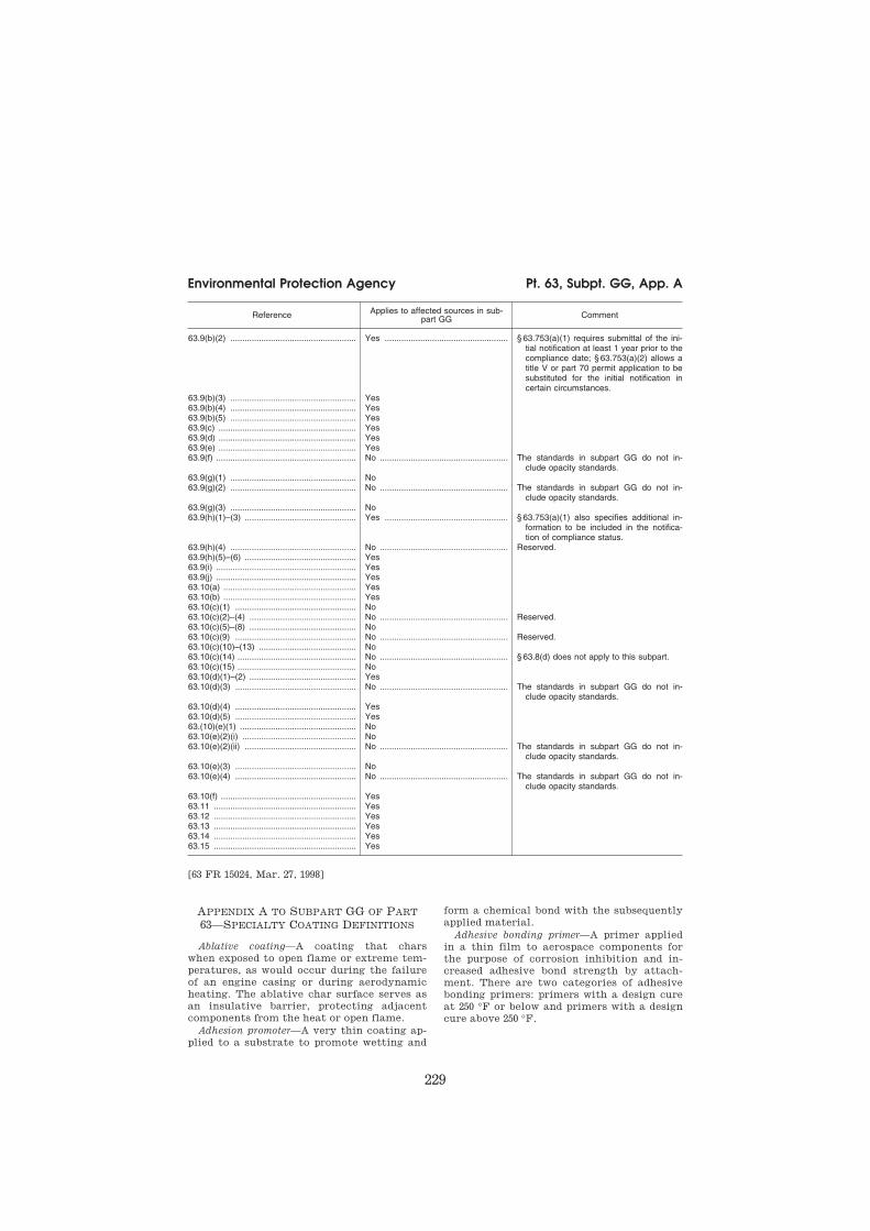
229
Environmental Protection Agency Pt. 63, Subpt. GG, App. A
Reference Applies to affected sources in sub-
part GG Comment
63.9(b)(2) ..................................................... Yes .................................................... § 63.753(a)(1) requires submittal of the ini-tial notification at least 1 year prior to the compliance date; § 63.753(a)(2) allows a title V or part 70 permit application to be substituted for the initial notification in certain circumstances.
63.9(b)(3) ..................................................... Yes 63.9(b)(4) ..................................................... Yes 63.9(b)(5) ..................................................... Yes 63.9(c) .......................................................... Yes 63.9(d) .......................................................... Yes 63.9(e) .......................................................... Yes 63.9(f) ........................................................... No ...................................................... The standards in subpart GG do not in-
clude opacity standards. 63.9(g)(1) ..................................................... No 63.9(g)(2) ..................................................... No ...................................................... The standards in subpart GG do not in-
clude opacity standards. 63.9(g)(3) ..................................................... No 63.9(h)(1)–(3) ............................................... Yes .................................................... § 63.753(a)(1) also specifies additional in-
formation to be included in the notifica-tion of compliance status.
63.9(h)(4) ..................................................... No ...................................................... Reserved. 63.9(h)(5)–(6) ............................................... Yes 63.9(i) ........................................................... Yes 63.9(j) ........................................................... Yes 63.10(a) ........................................................ Yes 63.10(b) ........................................................ Yes 63.10(c)(1) ................................................... No 63.10(c)(2)–(4) ............................................. No ...................................................... Reserved. 63.10(c)(5)–(8) ............................................. No 63.10(c)(9) ................................................... No ...................................................... Reserved. 63.10(c)(10)–(13) ......................................... No 63.10(c)(14) .................................................. No ...................................................... § 63.8(d) does not apply to this subpart. 63.10(c)(15) .................................................. No 63.10(d)(1)–(2) ............................................. Yes 63.10(d)(3) ................................................... No ...................................................... The standards in subpart GG do not in-
clude opacity standards. 63.10(d)(4) ................................................... Yes 63.10(d)(5) ................................................... Yes 63.(10)(e)(1) ................................................. No 63.10(e)(2)(i) ................................................ No 63.10(e)(2)(ii) ............................................... No ...................................................... The standards in subpart GG do not in-
clude opacity standards. 63.10(e)(3) ................................................... No 63.10(e)(4) ................................................... No ...................................................... The standards in subpart GG do not in-
clude opacity standards. 63.10(f) ......................................................... Yes 63.11 ............................................................ Yes 63.12 ............................................................ Yes 63.13 ............................................................ Yes 63.14 ............................................................ Yes 63.15 ............................................................ Yes
[63 FR 15024, Mar. 27, 1998]
APPENDIX A TO SUBPART GG OF PART
63—SPECIALTY COATING DEFINITIONS
Ablative coating—A coating that chars
when exposed to open flame or extreme tem-
peratures, as would occur during the failure
of an engine casing or during aerodynamic
heating. The ablative char surface serves as
an insulative barrier, protecting adjacent
components from the heat or open flame.
Adhesion promoter—A very thin coating ap-
plied to a substrate to promote wetting and
form a chemical bond with the subsequently
applied material.
Adhesive bonding primer—A primer applied
in a thin film to aerospace components for
the purpose of corrosion inhibition and in-
creased adhesive bond strength by attach-
ment. There are two categories of adhesive
bonding primers: primers with a design cure
at 250 °F or below and primers with a design
cure above 250 °F.
VerDate Mar<15>2010 17:45 Sep 05, 2014 Jkt 232159 PO 00000 Frm 00239 Fmt 8010 Sfmt 8002 Q:\40\40V11.TXT 31

230
40 CFR Ch. I (7–1–14 Edition) Pt. 63, Subpt. GG, App. A
Aerosol coating—A hand-held, pressurized, nonrefillable container that expels an adhe-sive or a coating in a finely divided spray when a valve on the container is depressed.
Antichafe coating—A coating applied to areas of moving aerospace components that may rub during normal operations or instal-lation.
Bearing coating—A coating applied to an antifriction bearing, a bearing housing, or the area adjacent to such a bearing in order to facilitate bearing function or to protect base material from excessive wear. A mate-rial shall not be classified as a bearing coat-ing if it can also be classified as a dry lubricative material or a solid film lubri-cant.
Bonding maskant—A temporary coating used to protect selected areas of aerospace parts from strong acid or alkaline solutions during processing for bonding.
Caulking and smoothing compounds—Semi- solid materials which are applied by hand ap-plication methods and are used to aero-dynamically smooth exterior vehicle sur-faces or fill cavities such as bolt hole ac-cesses. A material shall not be classified as a caulking and smoothing compound if it can also be classified as a sealant.
Chemical agent-resistant coating (CARC)—An exterior topcoat designed to withstand expo-sure to chemical warfare agents or the decontaminants used on these agents.
Clear coating—A transparent coating usu-ally applied over a colored opaque coating, metallic substrate, or placard to give im-proved gloss and protection to the color coat. In some cases, a clearcoat refers to any transparent coating without regard to sub-strate.
Commercial exterior aerodynamic structure
primer—A primer used on aerodynamic com-ponents and structures that protrude from the fuselage, such as wings and attached components, control surfaces, horizontal sta-bilizers, vertical fins, wing-to-body fairings, antennae, and landing gear and doors, for the purpose of extended corrosion protection and enhanced adhesion.
Commercial interior adhesive—Materials used in the bonding of passenger cabin inte-rior components. These components must meet the FAA fireworthiness requirements.
Compatible substrate primer—Includes two categories: compatible epoxy primer and ad-hesive primer. Compatible epoxy primer is primer that is compatible with the filled elastomeric coating and is epoxy based. The compatible substrate primer is an epoxy-pol-yamide primer used to promote adhesion of elastomeric coatings such as impact-resist-ant coatings. Adhesive primer is a coating that (1) inhibits corrosion and serves as a primer applied to bare metal surfaces or prior to adhesive application, or (2) is ap-plied to surfaces that can be expected to con-
tain fuel. Fuel tank coatings are excluded from this category.
Corrosion prevention system—A coating sys-tem that provides corrosion protection by displacing water and penetrating mating sur-faces, forming a protective barrier between the metal surface and moisture. Coatings containing oils or waxes are excluded from this category.
Critical use and line sealer maskant—A tem-porary coating, not covered under other maskant categories, used to protect selected areas of aerospace parts from strong acid or alkaline solutions such as those used in an-odizing, plating, chemical milling and proc-essing of magnesium, titanium, high- strength steel, high-precision aluminum chemical milling of deep cuts, and aluminum chemical milling of complex shapes. Mate-rials used for repairs or to bridge gaps left by scribing operations (i.e. line sealer) are also included in this category.
Cryogenic flexible primer—A primer designed to provide corrosion resistance, flexibility, and adhesion of subsequent coating systems when exposed to loads up to and surpassing the yield point of the substrate at cryogenic temperatures (¥275 °F and below).
Cryoprotective coating—A coating that insu-lates cryogenic or subcooled surfaces to limit propellant boil-off, maintain structural integrity of metallic structures during as-cent or re-entry, and prevent ice formation.
Cyanoacrylate adhesive—A fast-setting, sin-gle component adhesive that cures at room temperature. Also known as ‘‘super glue.’’
Dry lubricative material—A coating con-sisting of lauric acid, cetyl alcohol, waxes, or other non-cross linked or resin-bound mate-rials which act as a dry lubricant.
Electric or radiation-effect coating—A coat-ing or coating system engineered to interact, through absorption or reflection, with spe-cific regions of the electromagnetic energy spectrum, such as the ultraviolet, visible, in-frared, or microwave regions. Uses include, but are not limited to, lightning strike pro-tection, electromagnetic pulse (EMP) protec-tion, and radar avoidance. Coatings that have been designated as ‘‘classified’’ by the Department of Defense are exempt.
Electrostatic discharge and electromagnetic
interference (EMI) coating—A coating applied to space vehicles, missiles, aircraft radomes, and helicopter blades to disperse static en-ergy or reduce electromagnetic interference.
Elevated-temperature Skydrol-resistant com-
mercial primer—A primer applied primarily to commercial aircraft (or commercial aircraft adapted for military use) that must with-stand immersion in phosphate-ester (PE) hy-draulic fluid (Skydrol 500b or equivalent) at the elevated temperature of 150 °F for 1,000 hours.
Epoxy polyamide topcoat—A coating used where harder films are required or in some
VerDate Mar<15>2010 17:45 Sep 05, 2014 Jkt 232159 PO 00000 Frm 00240 Fmt 8010 Sfmt 8002 Q:\40\40V11.TXT 31
231
Environmental Protection Agency Pt. 63, Subpt. GG, App. A
areas where engraving is accomplished in camouflage colors.
Fire-resistant (interior) coating—For civilian aircraft, fire-resistant interior coatings are used on passenger cabin interior parts that are subject to the FAA fireworthiness re-quirements. For military aircraft, fire-re-sistant interior coatings are used on parts subject to the flammability requirements of MIL-STD-1630A and MIL-A-87721. For space applications, these coatings are used on parts subject to the flammability require-ments of SE-R-0006 and SSP 30233.
Flexible primer—A primer that meets flexi-bility requirements such as those needed for adhesive bond primed fastener heads or on surfaces expected to contain fuel. The flexi-ble coating is required because it provides a compatible, flexible substrate over bonded sheet rubber and rubber-type coatings as well as a flexible bridge between the fas-teners, skin, and skin-to-skin joints on outer aircraft skins. This flexible bridge allows more topcoat flexibility around fasteners and decreases the chance of the topcoat cracking around the fasteners. The result is better corrosion resistance.
Flight test coating—A coating applied to air-craft other than missiles or single-use air-craft prior to flight testing to protect the aircraft from corrosion and to provide re-quired marking during flight test evaluation.
Fuel tank adhesive—An adhesive used to bond components exposed to fuel and that must be compatible with fuel tank coatings.
Fuel tank coating—A coating applied to fuel tank components to inhibit corrosion and/or bacterial growth and to assure sealant adhe-sion in extreme environmental conditions.
High temperature coating—A coating de-signed to withstand temperatures of more than 350 °F.
Insulation covering—Material that is ap-plied to foam insulation to protect the insu-lation from mechanical or environmental damage.
Intermediate release coating—A thin coating applied beneath topcoats to assist in remov-ing the topcoat in depainting operations and generally to allow the use of less hazardous depainting methods.
Lacquer—A clear or pigmented coating for-mulated with a nitrocellulose or synthetic resin to dry by evaporation without a chem-ical reaction. Lacquers are resoluble in their original solvent.
Metalized epoxy coating—A coating that contains relatively large quantities of metal-lic pigmentation for appearance and/or added protection.
Mold release—A coating applied to a mold surface to prevent the molded piece from sticking to the mold as it is removed.
Nonstructural adhesive—An adhesive that bonds nonload bearing aerospace components in noncritical applications and is not cov-
ered in any other specialty adhesive cat-egories.
Optical anti-reflection coating—A coating with a low reflectance in the infrared and visible wavelength ranges, which is used for anti-reflection on or near optical and laser hardware.
Part marking coating—Coatings or inks used to make identifying markings on materials, components, and/or assemblies. These mark-ings may be either permanent or temporary.
Pretreatment coating—An organic coating that contains at least 0.5 percent acids by weight and is applied directly to metal or composite surfaces to provide surface etch-ing, corrosion resistance, adhesion, and ease of stripping.
Rain erosion-resistant coating—A coating or coating system used to protect the leading edges of parts such as flaps, stabilizers, radomes, engine inlet nacelles, etc. against erosion caused by rain impact during flight.
Rocket motor bonding adhesive—An adhesive used in rocket motor bonding applications.
Rocket motor nozzle coating—A catalyzed epoxy coating system used in elevated tem-perature applications on rocket motor noz-zles.
Rubber-based adhesive—Quick setting con-tact cements that provide a strong, yet flexi-ble, bond between two mating surfaces that may be of dissimilar materials.
Scale inhibitor—A coating that is applied to the surface of a part prior to thermal proc-essing to inhibit the formation of scale.
Screen print ink—Inks used in screen print-ing processes during fabrication of decora-tive laminates and decals.
Seal coat maskant—An overcoat applied over a maskant to improve abrasion and chemical resistance during production oper-ations.
Sealant—A material used to prevent the in-trusion of water, fuel, air, or other liquids or solids from certain areas of aerospace vehi-cles or components. There are two categories of sealants: extrudable/rollable/brushable sealants and sprayable sealants.
Silicone insulation material—Insulating ma-terial applied to exterior metal surfaces for protection from high temperatures caused by atmospheric friction or engine exhaust. These materials differ from ablative coatings in that they are not ‘‘sacrificial.’’
Solid film lubricant—A very thin coating consisting of a binder system containing as its chief pigment material one or more of the following: molybdenum, graphite, polytetra-fluoroethylene (PTFE), or other solids that act as a dry lubricant between faying sur-faces.
Specialized function coatings—Coatings that fulfill extremely specific engineering re-quirements that are limited in application and are characterized by low volume usage. This category excludes coatings covered in other Specialty Coating categories.
VerDate Mar<15>2010 17:45 Sep 05, 2014 Jkt 232159 PO 00000 Frm 00241 Fmt 8010 Sfmt 8002 Q:\40\40V11.TXT 31

232
40 CFR Ch. I (7–1–14 Edition) § 63.760
Structural autoclavable adhesive—An adhe-sive used to bond load-carrying aerospace components that is cured by heat and pres-sure in an autoclave.
Structural nonautoclavable adhesive—An ad-hesive cured under ambient conditions that is used to bond load-carrying aerospace com-ponents or for other critical functions, such as nonstructural bonding in the proximity of engines.
Temporary protective coating—A coating ap-plied to provide scratch or corrosion protec-tion during manufacturing, storage, or transportation. Two types include peelable protective coatings and alkaline removable coatings. These materials are not intended to protect against strong acid or alkaline so-lutions. Coatings that provide this type of protection from chemical processing are not included in this category.
Thermal control coating—Coatings formu-lated with specific thermal conductive or ra-diative properties to permit temperature control of the substrate.
Touch-up and Repair Coating—A coating used to cover minor coating imperfections appearing after the main coating operation.
Wet fastener installation coating—A primer or sealant applied by dipping, brushing, or daubing to fasteners that are installed before the coating is cured.
Wing coating—A corrosion-resistant top-coat that is resilient enough to withstand the flexing of the wings.
[63 FR 15026, Mar. 27, 1998]
Subpart HH—National Emission Standards for Hazardous Air Pollutants From Oil and Nat-ural Gas Production Facilities
SOURCE: 64 FR 32628, June 17, 1999, unless otherwise noted.
§ 63.760 Applicability and designation of affected source.
(a) This subpart applies to the owners and operators of the emission points, specified in paragraph (b) of this sec-tion that are located at oil and natural gas production facilities that meet the specified criteria in paragraphs (a)(1) and either (a)(2) or (a)(3) of this sec-tion.
(1) Facilities that are major or area sources of hazardous air pollutants (HAP) as defined in § 63.761. Emissions for major source determination pur-poses can be estimated using the max-imum natural gas or hydrocarbon liq-uid throughput, as appropriate, cal-culated in paragraphs (a)(1)(i) through
(iii) of this section. As an alternative to calculating the maximum natural gas or hydrocarbon liquid throughput, the owner or operator of a new or exist-ing source may use the facility’s design maximum natural gas or hydrocarbon liquid throughput to estimate the max-imum potential emissions. Other means to determine the facility’s major source status are allowed, pro-vided the information is documented and recorded to the Administrator’s satisfaction in accordance with § 63.10(b)(3). A facility that is deter-mined to be an area source, but subse-quently increases its emissions or its potential to emit above the major source levels, and becomes a major source, must comply thereafter with all provisions of this subpart applicable to a major source starting on the appli-cable compliance date specified in paragraph (f) of this section. Nothing in this paragraph is intended to pre-clude a source from limiting its poten-tial to emit through other appropriate mechanisms that may be available through the permitting authority.
(i) If the owner or operator docu-ments, to the Administrator’s satisfac-tion, a decline in annual natural gas or hydrocarbon liquid throughput, as ap-propriate, each year for the 5 years prior to October 15, 2012, the owner or operator shall calculate the maximum natural gas or hydrocarbon liquid throughput used to determine max-imum potential emissions according to the requirements specified in para-graph (a)(1)(i)(A) of this section. In all other circumstances, the owner or op-erator shall calculate the maximum throughput used to determine whether a facility is a major source in accord-ance with the requirements specified in paragraph (a)(1)(i)(B) of this section.
(A) The maximum natural gas or hy-drocarbon liquid throughput is the av-erage of the annual natural gas or hy-drocarbon liquid throughput for the 3 years prior to October 15, 2012, multi-plied by a factor of 1.2.
(B) The maximum natural gas or hy-drocarbon liquid throughput is the highest annual natural gas or hydro-carbon liquid throughput over the 5 years prior to October 15, 2012, multi-plied by a factor of 1.2.
VerDate Mar<15>2010 17:45 Sep 05, 2014 Jkt 232159 PO 00000 Frm 00242 Fmt 8010 Sfmt 8002 Q:\40\40V11.TXT 31

Appendix C
16
40 CFR Ch. I (7–1–14 Edition) § 63.6580
63.8802 What methods must I use to dem-
onstrate compliance with the emission
limitation for loop slitter adhesive use?
63.8806 How do I demonstrate initial compli-
ance with the emission limitations?
CONTINUOUS COMPLIANCE REQUIREMENTS
63.8810 How do I monitor and collect data to
demonstrate continuous compliance?
63.8812 How do I demonstrate continuous
compliance with the emission limita-
tions?
NOTIFICATIONS, REPORTS, AND RECORDS
63.8816 What notifications must I submit
and when?
63.8818 What reports must I submit and
when?
63.8820 What records must I keep?
63.8822 In what form and how long must I
keep my records?
OTHER REQUIREMENTS AND INFORMATION
63.8826 What parts of the General Provisions
apply to me?
63.8828 Who implements and enforces this
subpart?
63.8830 What definitions apply to this sub-
part?
TABLE 1 TO SUBPART MMMMM OF PART 63—
EMISSION LIMITS
TABLE 2 TO SUBPART MMMMM OF PART 63—
OPERATING LIMITS FOR NEW OR RECON-
STRUCTED FLAME LAMINATION AFFECTED
SOURCES
TABLE 3 TO SUBPART MMMMM OF PART 63—
PERFORMANCE TEST REQUIREMENTS FOR
NEW OR RECONSTRUCTED FLAME LAMINA-
TION AFFECTED SOURCES
TABLE 4 TO SUBPART MMMMM OF PART 63—
INITIAL COMPLIANCE WITH EMISSION LIM-
ITS
TABLE 5 TO SUBPART MMMMM OF PART 63—
CONTINUOUS COMPLIANCE WITH EMISSION
LIMITS AND OPERATING LIMITS
TABLE 6 TO SUBPART MMMMM OF PART 63—
REQUIREMENTS FOR REPORTS
TABLE 7 TO SUBPART MMMMM OF PART 63—
APPLICABILITY OF GENERAL PROVISIONS TO
SUBPART MMMMM
AUTHORITY: 42 U.S.C. 7401 et seq.
SOURCE: 57 FR 61992, Dec. 29, 1992, unless
otherwise noted.
Subpart ZZZZ—National Emissions Standards for Hazardous Air Pollutants for Stationary Re-ciprocating Internal Combus-tion Engines
SOURCE: 69 FR 33506, June 15, 2004, unless
otherwise noted.
WHAT THIS SUBPART COVERS
§ 63.6580 What is the purpose of sub-part ZZZZ?
Subpart ZZZZ establishes national
emission limitations and operating
limitations for hazardous air pollut-
ants (HAP) emitted from stationary re-
ciprocating internal combustion en-
gines (RICE) located at major and area
sources of HAP emissions. This subpart
also establishes requirements to dem-
onstrate initial and continuous compli-
ance with the emission limitations and
operating limitations.
[73 FR 3603, Jan. 18, 2008]
§ 63.6585 Am I subject to this subpart?
You are subject to this subpart if you
own or operate a stationary RICE at a
major or area source of HAP emissions,
except if the stationary RICE is being
tested at a stationary RICE test cell/
stand.
(a) A stationary RICE is any internal
combustion engine which uses recipro-
cating motion to convert heat energy
into mechanical work and which is not
mobile. Stationary RICE differ from
mobile RICE in that a stationary RICE
is not a non-road engine as defined at
40 CFR 1068.30, and is not used to propel
a motor vehicle or a vehicle used solely
for competition.
(b) A major source of HAP emissions
is a plant site that emits or has the po-
tential to emit any single HAP at a
rate of 10 tons (9.07 megagrams) or
more per year or any combination of
HAP at a rate of 25 tons (22.68
megagrams) or more per year, except
that for oil and gas production facili-
ties, a major source of HAP emissions
is determined for each surface site.
(c) An area source of HAP emissions
is a source that is not a major source.
(d) If you are an owner or operator of
an area source subject to this subpart,
your status as an entity subject to a
standard or other requirements under
this subpart does not subject you to
the obligation to obtain a permit under
40 CFR part 70 or 71, provided you are
not required to obtain a permit under
40 CFR 70.3(a) or 40 CFR 71.3(a) for a
reason other than your status as an
area source under this subpart. Not-
withstanding the previous sentence,
VerDate Sep<11>2014 13:42 Oct 28, 2014 Jkt 232162 PO 00000 Frm 00026 Fmt 8010 Sfmt 8010 Y:\SGML\232162.XXX 232162wre
ier-
avile
s on
DS
K5T
PT
VN
1PR
OD
with
CF
R

17
Environmental Protection Agency § 63.6590
you must continue to comply with the
provisions of this subpart as applicable.
(e) If you are an owner or operator of
a stationary RICE used for national se-
curity purposes, you may be eligible to
request an exemption from the require-
ments of this subpart as described in 40
CFR part 1068, subpart C.
(f) The emergency stationary RICE
listed in paragraphs (f)(1) through (3) of
this section are not subject to this sub-
part. The stationary RICE must meet
the definition of an emergency sta-
tionary RICE in § 63.6675, which in-
cludes operating according to the pro-
visions specified in § 63.6640(f).
(1) Existing residential emergency
stationary RICE located at an area
source of HAP emissions that do not
operate or are not contractually obli-
gated to be available for more than 15
hours per calendar year for the pur-
poses specified in § 63.6640(f)(2)(ii) and
(iii) and that do not operate for the
purpose specified in § 63.6640(f)(4)(ii).
(2) Existing commercial emergency
stationary RICE located at an area
source of HAP emissions that do not
operate or are not contractually obli-
gated to be available for more than 15
hours per calendar year for the pur-
poses specified in § 63.6640(f)(2)(ii) and
(iii) and that do not operate for the
purpose specified in § 63.6640(f)(4)(ii).
(3) Existing institutional emergency
stationary RICE located at an area
source of HAP emissions that do not
operate or are not contractually obli-
gated to be available for more than 15
hours per calendar year for the pur-
poses specified in § 63.6640(f)(2)(ii) and
(iii) and that do not operate for the
purpose specified in § 63.6640(f)(4)(ii).
[69 FR 33506, June 15, 2004, as amended at 73
FR 3603, Jan. 18, 2008; 78 FR 6700, Jan. 30,
2013]
§ 63.6590 What parts of my plant does this subpart cover?
This subpart applies to each affected
source.
(a) Affected source. An affected source
is any existing, new, or reconstructed
stationary RICE located at a major or
area source of HAP emissions, exclud-
ing stationary RICE being tested at a
stationary RICE test cell/stand.
(1) Existing stationary RICE.
(i) For stationary RICE with a site
rating of more than 500 brake horse-
power (HP) located at a major source of
HAP emissions, a stationary RICE is
existing if you commenced construc-
tion or reconstruction of the sta-
tionary RICE before December 19, 2002.
(ii) For stationary RICE with a site
rating of less than or equal to 500 brake
HP located at a major source of HAP
emissions, a stationary RICE is exist-
ing if you commenced construction or
reconstruction of the stationary RICE
before June 12, 2006.
(iii) For stationary RICE located at
an area source of HAP emissions, a sta-
tionary RICE is existing if you com-
menced construction or reconstruction
of the stationary RICE before June 12,
2006.
(iv) A change in ownership of an ex-
isting stationary RICE does not make
that stationary RICE a new or recon-
structed stationary RICE.
(2) New stationary RICE. (i) A sta-
tionary RICE with a site rating of
more than 500 brake HP located at a
major source of HAP emissions is new
if you commenced construction of the
stationary RICE on or after December
19, 2002.
(ii) A stationary RICE with a site
rating of equal to or less than 500 brake
HP located at a major source of HAP
emissions is new if you commenced
construction of the stationary RICE on
or after June 12, 2006.
(iii) A stationary RICE located at an
area source of HAP emissions is new if
you commenced construction of the
stationary RICE on or after June 12,
2006.
(3) Reconstructed stationary RICE. (i)
A stationary RICE with a site rating of
more than 500 brake HP located at a
major source of HAP emissions is re-
constructed if you meet the definition
of reconstruction in § 63.2 and recon-
struction is commenced on or after De-
cember 19, 2002.
(ii) A stationary RICE with a site
rating of equal to or less than 500 brake
HP located at a major source of HAP
emissions is reconstructed if you meet
the definition of reconstruction in § 63.2
and reconstruction is commenced on or
after June 12, 2006.
VerDate Sep<11>2014 13:42 Oct 28, 2014 Jkt 232162 PO 00000 Frm 00027 Fmt 8010 Sfmt 8010 Y:\SGML\232162.XXX 232162wre
ier-
avile
s on
DS
K5T
PT
VN
1PR
OD
with
CF
R

18
40 CFR Ch. I (7–1–14 Edition) § 63.6590
(iii) A stationary RICE located at an
area source of HAP emissions is recon-
structed if you meet the definition of
reconstruction in § 63.2 and reconstruc-
tion is commenced on or after June 12,
2006.
(b) Stationary RICE subject to limited requirements. (1) An affected source
which meets either of the criteria in
paragraphs (b)(1)(i) through (ii) of this
section does not have to meet the re-
quirements of this subpart and of sub-
part A of this part except for the ini-
tial notification requirements of
§ 63.6645(f).
(i) The stationary RICE is a new or
reconstructed emergency stationary
RICE with a site rating of more than
500 brake HP located at a major source
of HAP emissions that does not operate
or is not contractually obligated to be
available for more than 15 hours per
calendar year for the purposes specified
in § 63.6640(f)(2)(ii) and (iii).
(ii) The stationary RICE is a new or
reconstructed limited use stationary
RICE with a site rating of more than
500 brake HP located at a major source
of HAP emissions.
(2) A new or reconstructed stationary
RICE with a site rating of more than
500 brake HP located at a major source
of HAP emissions which combusts
landfill or digester gas equivalent to 10
percent or more of the gross heat input
on an annual basis must meet the ini-
tial notification requirements of
§ 63.6645(f) and the requirements of
§§ 63.6625(c), 63.6650(g), and 63.6655(c).
These stationary RICE do not have to
meet the emission limitations and op-
erating limitations of this subpart.
(3) The following stationary RICE do
not have to meet the requirements of
this subpart and of subpart A of this
part, including initial notification re-
quirements:
(i) Existing spark ignition 2 stroke
lean burn (2SLB) stationary RICE with
a site rating of more than 500 brake HP
located at a major source of HAP emis-
sions;
(ii) Existing spark ignition 4 stroke
lean burn (4SLB) stationary RICE with
a site rating of more than 500 brake HP
located at a major source of HAP emis-
sions;
(iii) Existing emergency stationary
RICE with a site rating of more than
500 brake HP located at a major source
of HAP emissions that does not operate
or is not contractually obligated to be
available for more than 15 hours per
calendar year for the purposes specified
in § 63.6640(f)(2)(ii) and (iii).
(iv) Existing limited use stationary
RICE with a site rating of more than
500 brake HP located at a major source
of HAP emissions;
(v) Existing stationary RICE with a
site rating of more than 500 brake HP
located at a major source of HAP emis-
sions that combusts landfill gas or di-
gester gas equivalent to 10 percent or
more of the gross heat input on an an-
nual basis;
(c) Stationary RICE subject to Regula-tions under 40 CFR Part 60. An affected
source that meets any of the criteria in
paragraphs (c)(1) through (7) of this
section must meet the requirements of
this part by meeting the requirements
of 40 CFR part 60 subpart IIII, for com-
pression ignition engines or 40 CFR
part 60 subpart JJJJ, for spark ignition
engines. No further requirements apply
for such engines under this part.
(1) A new or reconstructed stationary
RICE located at an area source;
(2) A new or reconstructed 2SLB sta-
tionary RICE with a site rating of less
than or equal to 500 brake HP located
at a major source of HAP emissions;
(3) A new or reconstructed 4SLB sta-
tionary RICE with a site rating of less
than 250 brake HP located at a major
source of HAP emissions;
(4) A new or reconstructed spark ig-
nition 4 stroke rich burn (4SRB) sta-
tionary RICE with a site rating of less
than or equal to 500 brake HP located
at a major source of HAP emissions;
(5) A new or reconstructed stationary
RICE with a site rating of less than or
equal to 500 brake HP located at a
major source of HAP emissions which
combusts landfill or digester gas equiv-
alent to 10 percent or more of the gross
heat input on an annual basis;
(6) A new or reconstructed emergency
or limited use stationary RICE with a
site rating of less than or equal to 500
brake HP located at a major source of
HAP emissions;
(7) A new or reconstructed compres-
sion ignition (CI) stationary RICE with
a site rating of less than or equal to 500
VerDate Sep<11>2014 13:42 Oct 28, 2014 Jkt 232162 PO 00000 Frm 00028 Fmt 8010 Sfmt 8010 Y:\SGML\232162.XXX 232162wre
ier-
avile
s on
DS
K5T
PT
VN
1PR
OD
with
CF
R

19
Environmental Protection Agency § 63.6595
brake HP located at a major source of
HAP emissions.
[69 FR 33506, June 15, 2004, as amended at 73
FR 3604, Jan. 18, 2008; 75 FR 9674, Mar. 3, 2010;
75 FR 37733, June 30, 2010; 75 FR 51588, Aug.
20, 2010; 78 FR 6700, Jan. 30, 2013]
§ 63.6595 When do I have to comply with this subpart?
(a) Affected sources. (1) If you have an
existing stationary RICE, excluding ex-
isting non-emergency CI stationary
RICE, with a site rating of more than
500 brake HP located at a major source
of HAP emissions, you must comply
with the applicable emission limita-
tions, operating limitations and other
requirements no later than June 15,
2007. If you have an existing non-emer-
gency CI stationary RICE with a site
rating of more than 500 brake HP lo-
cated at a major source of HAP emis-
sions, an existing stationary CI RICE
with a site rating of less than or equal
to 500 brake HP located at a major
source of HAP emissions, or an existing
stationary CI RICE located at an area
source of HAP emissions, you must
comply with the applicable emission
limitations, operating limitations, and
other requirements no later than May
3, 2013. If you have an existing sta-
tionary SI RICE with a site rating of
less than or equal to 500 brake HP lo-
cated at a major source of HAP emis-
sions, or an existing stationary SI
RICE located at an area source of HAP
emissions, you must comply with the
applicable emission limitations, oper-
ating limitations, and other require-
ments no later than October 19, 2013. (2) If you start up your new or recon-
structed stationary RICE with a site
rating of more than 500 brake HP lo-
cated at a major source of HAP emis-
sions before August 16, 2004, you must
comply with the applicable emission
limitations and operating limitations
in this subpart no later than August 16,
2004. (3) If you start up your new or recon-
structed stationary RICE with a site
rating of more than 500 brake HP lo-
cated at a major source of HAP emis-
sions after August 16, 2004, you must
comply with the applicable emission
limitations and operating limitations
in this subpart upon startup of your af-
fected source.
(4) If you start up your new or recon-
structed stationary RICE with a site
rating of less than or equal to 500 brake
HP located at a major source of HAP
emissions before January 18, 2008, you
must comply with the applicable emis-
sion limitations and operating limita-
tions in this subpart no later than Jan-
uary 18, 2008.
(5) If you start up your new or recon-
structed stationary RICE with a site
rating of less than or equal to 500 brake
HP located at a major source of HAP
emissions after January 18, 2008, you
must comply with the applicable emis-
sion limitations and operating limita-
tions in this subpart upon startup of
your affected source.
(6) If you start up your new or recon-
structed stationary RICE located at an
area source of HAP emissions before
January 18, 2008, you must comply with
the applicable emission limitations and
operating limitations in this subpart
no later than January 18, 2008.
(7) If you start up your new or recon-
structed stationary RICE located at an
area source of HAP emissions after
January 18, 2008, you must comply with
the applicable emission limitations and
operating limitations in this subpart
upon startup of your affected source.
(b) Area sources that become major
sources. If you have an area source that
increases its emissions or its potential
to emit such that it becomes a major
source of HAP, the compliance dates in
paragraphs (b)(1) and (2) of this section
apply to you.
(1) Any stationary RICE for which
construction or reconstruction is com-
menced after the date when your area
source becomes a major source of HAP
must be in compliance with this sub-
part upon startup of your affected
source.
(2) Any stationary RICE for which
construction or reconstruction is com-
menced before your area source be-
comes a major source of HAP must be
in compliance with the provisions of
this subpart that are applicable to
RICE located at major sources within 3
years after your area source becomes a
major source of HAP.
(c) If you own or operate an affected
source, you must meet the applicable
VerDate Sep<11>2014 13:42 Oct 28, 2014 Jkt 232162 PO 00000 Frm 00029 Fmt 8010 Sfmt 8010 Y:\SGML\232162.XXX 232162wre
ier-
avile
s on
DS
K5T
PT
VN
1PR
OD
with
CF
R

20
40 CFR Ch. I (7–1–14 Edition) § 63.6600
notification requirements in § 63.6645 and in 40 CFR part 63, subpart A.
[69 FR 33506, June 15, 2004, as amended at 73
FR 3604, Jan. 18, 2008; 75 FR 9675, Mar. 3, 2010;
75 FR 51589, Aug. 20, 2010; 78 FR 6701, Jan. 30,
2013]
EMISSION AND OPERATING LIMITATIONS
§ 63.6600 What emission limitations and operating limitations must I meet if I own or operate a sta-tionary RICE with a site rating of more than 500 brake HP located at a major source of HAP emissions?
Compliance with the numerical emis-sion limitations established in this subpart is based on the results of test-ing the average of three 1-hour runs using the testing requirements and procedures in § 63.6620 and Table 4 to this subpart.
(a) If you own or operate an existing, new, or reconstructed spark ignition 4SRB stationary RICE with a site rat-ing of more than 500 brake HP located at a major source of HAP emissions, you must comply with the emission limitations in Table 1a to this subpart and the operating limitations in Table 1b to this subpart which apply to you.
(b) If you own or operate a new or re-constructed 2SLB stationary RICE with a site rating of more than 500 brake HP located at major source of
HAP emissions, a new or reconstructed
4SLB stationary RICE with a site rat-
ing of more than 500 brake HP located
at major source of HAP emissions, or a
new or reconstructed CI stationary
RICE with a site rating of more than
500 brake HP located at a major source
of HAP emissions, you must comply
with the emission limitations in Table
2a to this subpart and the operating
limitations in Table 2b to this subpart
which apply to you. (c) If you own or operate any of the
following stationary RICE with a site
rating of more than 500 brake HP lo-
cated at a major source of HAP emis-
sions, you do not need to comply with
the emission limitations in Tables 1a,
2a, 2c, and 2d to this subpart or oper-
ating limitations in Tables 1b and 2b to
this subpart: an existing 2SLB sta-
tionary RICE; an existing 4SLB sta-
tionary RICE; a stationary RICE that
combusts landfill gas or digester gas
equivalent to 10 percent or more of the
gross heat input on an annual basis; an
emergency stationary RICE; or a lim-
ited use stationary RICE.
(d) If you own or operate an existing
non-emergency stationary CI RICE
with a site rating of more than 500
brake HP located at a major source of
HAP emissions, you must comply with
the emission limitations in Table 2c to
this subpart and the operating limita-
tions in Table 2b to this subpart which
apply to you.
[73 FR 3605, Jan. 18, 2008, as amended at 75
FR 9675, Mar. 3, 2010]
§ 63.6601 What emission limitations must I meet if I own or operate a new or reconstructed 4SLB sta-tionary RICE with a site rating of greater than or equal to 250 brake HP and less than or equal to 500 brake HP located at a major source of HAP emissions?
Compliance with the numerical emis-
sion limitations established in this
subpart is based on the results of test-
ing the average of three 1-hour runs
using the testing requirements and
procedures in § 63.6620 and Table 4 to
this subpart. If you own or operate a
new or reconstructed 4SLB stationary
RICE with a site rating of greater than
or equal to 250 and less than or equal to
500 brake HP located at major source of
HAP emissions manufactured on or
after January 1, 2008, you must comply
with the emission limitations in Table
2a to this subpart and the operating
limitations in Table 2b to this subpart
which apply to you.
[73 FR 3605, Jan. 18, 2008, as amended at 75
FR 9675, Mar. 3, 2010; 75 FR 51589, Aug. 20,
2010]
§ 63.6602 What emission limitations and other requirements must I meet if I own or operate an existing stationary RICE with a site rating of equal to or less than 500 brake HP located at a major source of HAP emissions?
If you own or operate an existing sta-
tionary RICE with a site rating of
equal to or less than 500 brake HP lo-
cated at a major source of HAP emis-
sions, you must comply with the emis-
sion limitations and other require-
ments in Table 2c to this subpart which
VerDate Sep<11>2014 13:42 Oct 28, 2014 Jkt 232162 PO 00000 Frm 00030 Fmt 8010 Sfmt 8010 Y:\SGML\232162.XXX 232162wre
ier-
avile
s on
DS
K5T
PT
VN
1PR
OD
with
CF
R

21
Environmental Protection Agency § 63.6603
apply to you. Compliance with the nu-
merical emission limitations estab-
lished in this subpart is based on the
results of testing the average of three
1-hour runs using the testing require-
ments and procedures in § 63.6620 and
Table 4 to this subpart.
[78 FR 6701, Jan. 30, 2013]
§ 63.6603 What emission limitations, operating limitations, and other re-quirements must I meet if I own or operate an existing stationary RICE located at an area source of HAP emissions?
Compliance with the numerical emis-
sion limitations established in this
subpart is based on the results of test-
ing the average of three 1-hour runs
using the testing requirements and
procedures in § 63.6620 and Table 4 to
this subpart.
(a) If you own or operate an existing
stationary RICE located at an area
source of HAP emissions, you must
comply with the requirements in Table
2d to this subpart and the operating
limitations in Table 2b to this subpart
that apply to you.
(b) If you own or operate an existing
stationary non-emergency CI RICE
with a site rating of more than 300 HP
located at an area source of HAP that
meets either paragraph (b)(1) or (2) of
this section, you do not have to meet
the numerical CO emission limitations
specified in Table 2d of this subpart.
Existing stationary non-emergency CI
RICE with a site rating of more than
300 HP located at an area source of
HAP that meet either paragraph (b)(1)
or (2) of this section must meet the
management practices that are shown
for stationary non-emergency CI RICE
with a site rating of less than or equal
to 300 HP in Table 2d of this subpart.
(1) The area source is located in an
area of Alaska that is not accessible by
the Federal Aid Highway System
(FAHS).
(2) The stationary RICE is located at
an area source that meets paragraphs
(b)(2)(i), (ii), and (iii) of this section.
(i) The only connection to the FAHS
is through the Alaska Marine Highway
System (AMHS), or the stationary
RICE operation is within an isolated
grid in Alaska that is not connected to
the statewide electrical grid referred to
as the Alaska Railbelt Grid.
(ii) At least 10 percent of the power
generated by the stationary RICE on
an annual basis is used for residential
purposes.
(iii) The generating capacity of the
area source is less than 12 megawatts,
or the stationary RICE is used exclu-
sively for backup power for renewable
energy.
(c) If you own or operate an existing
stationary non-emergency CI RICE
with a site rating of more than 300 HP
located on an offshore vessel that is an
area source of HAP and is a nonroad
vehicle that is an Outer Continental
Shelf (OCS) source as defined in 40 CFR
55.2, you do not have to meet the nu-
merical CO emission limitations speci-
fied in Table 2d of this subpart. You
must meet all of the following manage-
ment practices:
(1) Change oil every 1,000 hours of op-
eration or annually, whichever comes
first. Sources have the option to utilize
an oil analysis program as described in
§ 63.6625(i) in order to extend the speci-
fied oil change requirement.
(2) Inspect and clean air filters every
750 hours of operation or annually,
whichever comes first, and replace as
necessary.
(3) Inspect fuel filters and belts, if in-
stalled, every 750 hours of operation or
annually, whichever comes first, and
replace as necessary.
(4) Inspect all flexible hoses every
1,000 hours of operation or annually,
whichever comes first, and replace as
necessary.
(d) If you own or operate an existing
non-emergency CI RICE with a site rat-
ing of more than 300 HP located at an
area source of HAP emissions that is
certified to the Tier 1 or Tier 2 emis-
sion standards in Table 1 of 40 CFR
89.112 and that is subject to an enforce-
able state or local standard that re-
quires the engine to be replaced no
later than June 1, 2018, you may until
January 1, 2015, or 12 years after the in-
stallation date of the engine (which-
ever is later), but not later than June
1, 2018, choose to comply with the man-
agement practices that are shown for
stationary non-emergency CI RICE
with a site rating of less than or equal
VerDate Sep<11>2014 13:42 Oct 28, 2014 Jkt 232162 PO 00000 Frm 00031 Fmt 8010 Sfmt 8010 Y:\SGML\232162.XXX 232162wre
ier-
avile
s on
DS
K5T
PT
VN
1PR
OD
with
CF
R
22
40 CFR Ch. I (7–1–14 Edition) § 63.6604
to 300 HP in Table 2d of this subpart in-
stead of the applicable emission limita-
tions in Table 2d, operating limitations
in Table 2b, and crankcase ventilation
system requirements in § 63.6625(g). You
must comply with the emission limita-
tions in Table 2d and operating limita-
tions in Table 2b that apply for non-
emergency CI RICE with a site rating
of more than 300 HP located at an area
source of HAP emissions by January 1,
2015, or 12 years after the installation
date of the engine (whichever is later),
but not later than June 1, 2018. You
must also comply with the crankcase
ventilation system requirements in
§ 63.6625(g) by January 1, 2015, or 12
years after the installation date of the
engine (whichever is later), but not
later than June 1, 2018.
(e) If you own or operate an existing
non-emergency CI RICE with a site rat-
ing of more than 300 HP located at an
area source of HAP emissions that is
certified to the Tier 3 (Tier 2 for en-
gines above 560 kilowatt (kW)) emis-
sion standards in Table 1 of 40 CFR
89.112, you may comply with the re-
quirements under this part by meeting
the requirements for Tier 3 engines
(Tier 2 for engines above 560 kW) in 40
CFR part 60 subpart IIII instead of the
emission limitations and other require-
ments that would otherwise apply
under this part for existing non-emer-
gency CI RICE with a site rating of
more than 300 HP located at an area
source of HAP emissions.
(f) An existing non-emergency SI
4SLB and 4SRB stationary RICE with a
site rating of more than 500 HP located
at area sources of HAP must meet the
definition of remote stationary RICE
in § 63.6675 on the initial compliance
date for the engine, October 19, 2013, in
order to be considered a remote sta-
tionary RICE under this subpart. Own-
ers and operators of existing non-emer-
gency SI 4SLB and 4SRB stationary
RICE with a site rating of more than
500 HP located at area sources of HAP
that meet the definition of remote sta-
tionary RICE in § 63.6675 of this subpart
as of October 19, 2013 must evaluate the
status of their stationary RICE every
12 months. Owners and operators must
keep records of the initial and annual
evaluation of the status of the engine.
If the evaluation indicates that the
stationary RICE no longer meets the
definition of remote stationary RICE
in § 63.6675 of this subpart, the owner or
operator must comply with all of the
requirements for existing non-emer-
gency SI 4SLB and 4SRB stationary
RICE with a site rating of more than
500 HP located at area sources of HAP
that are not remote stationary RICE
within 1 year of the evaluation.
[75 FR 9675, Mar. 3, 2010, as amended at 75 FR
51589, Aug. 20, 2010; 76 FR 12866, Mar. 9, 2011;
78 FR 6701, Jan. 30, 2013]
§ 63.6604 What fuel requirements must I meet if I own or operate a sta-tionary CI RICE?
(a) If you own or operate an existing
non-emergency, non-black start CI sta-
tionary RICE with a site rating of
more than 300 brake HP with a dis-
placement of less than 30 liters per cyl-
inder that uses diesel fuel, you must
use diesel fuel that meets the require-
ments in 40 CFR 80.510(b) for nonroad
diesel fuel. (b) Beginning January 1, 2015, if you
own or operate an existing emergency
CI stationary RICE with a site rating
of more than 100 brake HP and a dis-
placement of less than 30 liters per cyl-
inder that uses diesel fuel and operates
or is contractually obligated to be
available for more than 15 hours per
calendar year for the purposes specified
in § 63.6640(f)(2)(ii) and (iii) or that op-
erates for the purpose specified in
§ 63.6640(f)(4)(ii), you must use diesel
fuel that meets the requirements in 40
CFR 80.510(b) for nonroad diesel fuel,
except that any existing diesel fuel
purchased (or otherwise obtained) prior
to January 1, 2015, may be used until
depleted. (c) Beginning January 1, 2015, if you
own or operate a new emergency CI
stationary RICE with a site rating of
more than 500 brake HP and a displace-
ment of less than 30 liters per cylinder
located at a major source of HAP that
uses diesel fuel and operates or is con-
tractually obligated to be available for
more than 15 hours per calendar year
for the purposes specified in
§ 63.6640(f)(2)(ii) and (iii), you must use
diesel fuel that meets the requirements
in 40 CFR 80.510(b) for nonroad diesel
fuel, except that any existing diesel
fuel purchased (or otherwise obtained)
VerDate Sep<11>2014 13:42 Oct 28, 2014 Jkt 232162 PO 00000 Frm 00032 Fmt 8010 Sfmt 8010 Y:\SGML\232162.XXX 232162wre
ier-
avile
s on
DS
K5T
PT
VN
1PR
OD
with
CF
R

23
Environmental Protection Agency § 63.6610
prior to January 1, 2015, may be used until depleted.
(d) Existing CI stationary RICE lo-cated in Guam, American Samoa, the Commonwealth of the Northern Mar-iana Islands, at area sources in areas of Alaska that meet either § 63.6603(b)(1) or § 63.6603(b)(2), or are on offshore ves-sels that meet § 63.6603(c) are exempt from the requirements of this section.
[78 FR 6702, Jan. 30, 2013]
GENERAL COMPLIANCE REQUIREMENTS
§ 63.6605 What are my general require-ments for complying with this sub-part?
(a) You must be in compliance with the emission limitations, operating limitations, and other requirements in this subpart that apply to you at all times.
(b) At all times you must operate and maintain any affected source, includ-ing associated air pollution control equipment and monitoring equipment, in a manner consistent with safety and good air pollution control practices for minimizing emissions. The general duty to minimize emissions does not require you to make any further efforts to reduce emissions if levels required by this standard have been achieved. Determination of whether such oper-ation and maintenance procedures are being used will be based on information available to the Administrator which may include, but is not limited to, monitoring results, review of operation and maintenance procedures, review of operation and maintenance records, and inspection of the source.
[75 FR 9675, Mar. 3, 2010, as amended at 78 FR
6702, Jan. 30, 2013]
TESTING AND INITIAL COMPLIANCE REQUIREMENTS
§ 63.6610 By what date must I conduct the initial performance tests or other initial compliance demonstra-tions if I own or operate a sta-tionary RICE with a site rating of more than 500 brake HP located at a major source of HAP emissions?
If you own or operate a stationary
RICE with a site rating of more than
500 brake HP located at a major source
of HAP emissions you are subject to
the requirements of this section.
(a) You must conduct the initial per-
formance test or other initial compli-
ance demonstrations in Table 4 to this
subpart that apply to you within 180
days after the compliance date that is
specified for your stationary RICE in
§ 63.6595 and according to the provisions
in § 63.7(a)(2).
(b) If you commenced construction or
reconstruction between December 19,
2002 and June 15, 2004 and own or oper-
ate stationary RICE with a site rating
of more than 500 brake HP located at a
major source of HAP emissions, you
must demonstrate initial compliance
with either the proposed emission limi-
tations or the promulgated emission
limitations no later than February 10,
2005 or no later than 180 days after
startup of the source, whichever is
later, according to § 63.7(a)(2)(ix).
(c) If you commenced construction or
reconstruction between December 19,
2002 and June 15, 2004 and own or oper-
ate stationary RICE with a site rating
of more than 500 brake HP located at a
major source of HAP emissions, and
you chose to comply with the proposed
emission limitations when dem-
onstrating initial compliance, you
must conduct a second performance
test to demonstrate compliance with
the promulgated emission limitations
by December 13, 2007 or after startup of
the source, whichever is later, accord-
ing to § 63.7(a)(2)(ix).
(d) An owner or operator is not re-
quired to conduct an initial perform-
ance test on units for which a perform-
ance test has been previously con-
ducted, but the test must meet all of
the conditions described in paragraphs
(d)(1) through (5) of this section.
(1) The test must have been con-
ducted using the same methods speci-
fied in this subpart, and these methods
must have been followed correctly.
(2) The test must not be older than 2
years.
(3) The test must be reviewed and ac-
cepted by the Administrator.
(4) Either no process or equipment
changes must have been made since the
test was performed, or the owner or op-
erator must be able to demonstrate
that the results of the performance
test, with or without adjustments, reli-
ably demonstrate compliance despite
process or equipment changes.
VerDate Sep<11>2014 13:42 Oct 28, 2014 Jkt 232162 PO 00000 Frm 00033 Fmt 8010 Sfmt 8010 Y:\SGML\232162.XXX 232162wre
ier-
avile
s on
DS
K5T
PT
VN
1PR
OD
with
CF
R
24
40 CFR Ch. I (7–1–14 Edition) § 63.6611
(5) The test must be conducted at any
load condition within plus or minus 10
percent of 100 percent load.
[69 FR 33506, June 15, 2004, as amended at 73
FR 3605, Jan. 18, 2008]
§ 63.6611 By what date must I conduct the initial performance tests or other initial compliance demonstra-tions if I own or operate a new or reconstructed 4SLB SI stationary RICE with a site rating of greater than or equal to 250 and less than or equal to 500 brake HP located at a major source of HAP emissions?
If you own or operate a new or recon-
structed 4SLB stationary RICE with a
site rating of greater than or equal to
250 and less than or equal to 500 brake
HP located at a major source of HAP
emissions, you must conduct an initial
performance test within 240 days after
the compliance date that is specified
for your stationary RICE in § 63.6595
and according to the provisions speci-
fied in Table 4 to this subpart, as ap-
propriate.
[73 FR 3605, Jan. 18, 2008, as amended at 75
FR 51589, Aug. 20, 2010]
§ 63.6612 By what date must I conduct the initial performance tests or other initial compliance demonstra-tions if I own or operate an existing stationary RICE with a site rating of less than or equal to 500 brake HP located at a major source of HAP emissions or an existing sta-tionary RICE located at an area source of HAP emissions?
If you own or operate an existing sta-
tionary RICE with a site rating of less
than or equal to 500 brake HP located
at a major source of HAP emissions or
an existing stationary RICE located at
an area source of HAP emissions you
are subject to the requirements of this
section.
(a) You must conduct any initial per-
formance test or other initial compli-
ance demonstration according to Ta-
bles 4 and 5 to this subpart that apply
to you within 180 days after the com-
pliance date that is specified for your
stationary RICE in § 63.6595 and accord-
ing to the provisions in § 63.7(a)(2).
(b) An owner or operator is not re-
quired to conduct an initial perform-
ance test on a unit for which a per-
formance test has been previously con-
ducted, but the test must meet all of the conditions described in paragraphs (b)(1) through (4) of this section.
(1) The test must have been con-ducted using the same methods speci-fied in this subpart, and these methods must have been followed correctly.
(2) The test must not be older than 2 years.
(3) The test must be reviewed and ac-
cepted by the Administrator. (4) Either no process or equipment
changes must have been made since the
test was performed, or the owner or op-
erator must be able to demonstrate
that the results of the performance
test, with or without adjustments, reli-
ably demonstrate compliance despite
process or equipment changes.
[75 FR 9676, Mar. 3, 2010, as amended at 75 FR
51589, Aug. 20, 2010]
§ 63.6615 When must I conduct subse-quent performance tests?
If you must comply with the emis-
sion limitations and operating limita-
tions, you must conduct subsequent
performance tests as specified in Table
3 of this subpart.
§ 63.6620 What performance tests and other procedures must I use?
(a) You must conduct each perform-
ance test in Tables 3 and 4 of this sub-
part that applies to you. (b) Each performance test must be
conducted according to the require-
ments that this subpart specifies in
Table 4 to this subpart. If you own or
operate a non-operational stationary
RICE that is subject to performance
testing, you do not need to start up the
engine solely to conduct the perform-
ance test. Owners and operators of a
non-operational engine can conduct the
performance test when the engine is
started up again. The test must be con-
ducted at any load condition within
plus or minus 10 percent of 100 percent
load for the stationary RICE listed in
paragraphs (b)(1) through (4) of this
section. (1) Non-emergency 4SRB stationary
RICE with a site rating of greater than
500 brake HP located at a major source
of HAP emissions. (2) New non-emergency 4SLB sta-
tionary RICE with a site rating of
greater than or equal to 250 brake HP
VerDate Sep<11>2014 13:42 Oct 28, 2014 Jkt 232162 PO 00000 Frm 00034 Fmt 8010 Sfmt 8010 Y:\SGML\232162.XXX 232162wre
ier-
avile
s on
DS
K5T
PT
VN
1PR
OD
with
CF
R

25
Environmental Protection Agency § 63.6620
located at a major source of HAP emis-
sions.
(3) New non-emergency 2SLB sta-
tionary RICE with a site rating of
greater than 500 brake HP located at a
major source of HAP emissions.
(4) New non-emergency CI stationary
RICE with a site rating of greater than
500 brake HP located at a major source
of HAP emissions.
(c) [Reserved]
(d) You must conduct three separate
test runs for each performance test re-
quired in this section, as specified in
§ 63.7(e)(3). Each test run must last at
least 1 hour, unless otherwise specified
in this subpart.
(e)(1) You must use Equation 1 of this
section to determine compliance with
the percent reduction requirement:
Where:
Ci = concentration of carbon monoxide (CO),
total hydrocarbons (THC), or formalde-
hyde at the control device inlet,
Co = concentration of CO, THC, or formalde-
hyde at the control device outlet, and
R = percent reduction of CO, THC, or form-
aldehyde emissions.
(2) You must normalize the CO, THC,
or formaldehyde concentrations at the
inlet and outlet of the control device to
a dry basis and to 15 percent oxygen, or
an equivalent percent carbon dioxide
(CO2). If pollutant concentrations are
to be corrected to 15 percent oxygen
and CO2 concentration is measured in
lieu of oxygen concentration measure-
ment, a CO2 correction factor is need-
ed. Calculate the CO2 correction factor
as described in paragraphs (e)(2)(i)
through (iii) of this section.
(i) Calculate the fuel-specific Fo value for the fuel burned during the
test using values obtained from Method
19, Section 5.2, and the following equa-
tion:
Where:
Fo = Fuel factor based on the ratio of oxygen
volume to the ultimate CO2 volume pro-
duced by the fuel at zero percent excess
air.
0.209 = Fraction of air that is oxygen, per-
cent/100.
Fd = Ratio of the volume of dry effluent gas
to the gross calorific value of the fuel
from Method 19, dsm3/J (dscf/106 Btu).
Fc = Ratio of the volume of CO2 produced to
the gross calorific value of the fuel from
Method 19, dsm3/J (dscf/106 Btu)
(ii) Calculate the CO2 correction fac-
tor for correcting measurement data to
15 percent O2, as follows:
Where:
XCO2 = CO2 correction factor, percent.
5.9 = 20.9 percent O2—15 percent O2, the de-
fined O2 correction value, percent.
(iii) Calculate the CO, THC, and
formaldehyde gas concentrations ad-
justed to 15 percent O2 using CO2 as fol-
lows:
VerDate Sep<11>2014 13:42 Oct 28, 2014 Jkt 232162 PO 00000 Frm 00035 Fmt 8010 Sfmt 8010 Y:\SGML\232162.XXX 232162 ER
30JA
13.0
07<
/GP
H>
ER
30JA
13.0
08<
/GP
H>
ER
30JA
13.0
09<
/GP
H>
wre
ier-
avile
s on
DS
K5T
PT
VN
1PR
OD
with
CF
R

26
40 CFR Ch. I (7–1–14 Edition) § 63.6620
Where:
Cadj = Calculated concentration of CO, THC,
or formaldehyde adjusted to 15 percent
O2. Cd = Measured concentration of CO, THC, or
formaldehyde, uncorrected. XCO2 = CO2 correction factor, percent. %CO2 = Measured CO2 concentration meas-
ured, dry basis, percent.
(f) If you comply with the emission
limitation to reduce CO and you are
not using an oxidation catalyst, if you
comply with the emission limitation to
reduce formaldehyde and you are not
using NSCR, or if you comply with the
emission limitation to limit the con-
centration of formaldehyde in the sta-
tionary RICE exhaust and you are not
using an oxidation catalyst or NSCR,
you must petition the Administrator
for operating limitations to be estab-
lished during the initial performance
test and continuously monitored there-
after; or for approval of no operating
limitations. You must not conduct the
initial performance test until after the
petition has been approved by the Ad-
ministrator. (g) If you petition the Administrator
for approval of operating limitations,
your petition must include the infor-
mation described in paragraphs (g)(1)
through (5) of this section. (1) Identification of the specific pa-
rameters you propose to use as oper-
ating limitations; (2) A discussion of the relationship
between these parameters and HAP
emissions, identifying how HAP emis-
sions change with changes in these pa-
rameters, and how limitations on these
parameters will serve to limit HAP
emissions; (3) A discussion of how you will es-
tablish the upper and/or lower values
for these parameters which will estab-
lish the limits on these parameters in
the operating limitations; (4) A discussion identifying the meth-
ods you will use to measure and the in-
struments you will use to monitor
these parameters, as well as the rel-
ative accuracy and precision of these
methods and instruments; and
(5) A discussion identifying the fre-
quency and methods for recalibrating
the instruments you will use for moni-
toring these parameters.
(h) If you petition the Administrator
for approval of no operating limita-
tions, your petition must include the
information described in paragraphs
(h)(1) through (7) of this section.
(1) Identification of the parameters
associated with operation of the sta-
tionary RICE and any emission control
device which could change inten-
tionally (e.g., operator adjustment,
automatic controller adjustment, etc.)
or unintentionally (e.g., wear and tear,
error, etc.) on a routine basis or over
time;
(2) A discussion of the relationship, if
any, between changes in the param-
eters and changes in HAP emissions;
(3) For the parameters which could
change in such a way as to increase
HAP emissions, a discussion of whether
establishing limitations on the param-
eters would serve to limit HAP emis-
sions;
(4) For the parameters which could
change in such a way as to increase
HAP emissions, a discussion of how
you could establish upper and/or lower
values for the parameters which would
establish limits on the parameters in
operating limitations;
(5) For the parameters, a discussion
identifying the methods you could use
to measure them and the instruments
you could use to monitor them, as well
as the relative accuracy and precision
of the methods and instruments;
(6) For the parameters, a discussion
identifying the frequency and methods
for recalibrating the instruments you
could use to monitor them; and
(7) A discussion of why, from your
point of view, it is infeasible or unrea-
sonable to adopt the parameters as op-
erating limitations.
(i) The engine percent load during a
performance test must be determined
by documenting the calculations, as-
sumptions, and measurement devices
VerDate Sep<11>2014 13:42 Oct 28, 2014 Jkt 232162 PO 00000 Frm 00036 Fmt 8010 Sfmt 8010 Y:\SGML\232162.XXX 232162 ER
30JA
13.0
10<
/GP
H>
wre
ier-
avile
s on
DS
K5T
PT
VN
1PR
OD
with
CF
R

27
Environmental Protection Agency § 63.6625
used to measure or estimate the per-cent load in a specific application. A written report of the average percent load determination must be included in the notification of compliance status. The following information must be in-cluded in the written report: the engine model number, the engine manufac-turer, the year of purchase, the manu-
facturer’s site-rated brake horsepower,
the ambient temperature, pressure, and
humidity during the performance test,
and all assumptions that were made to
estimate or calculate percent load dur-
ing the performance test must be clear-
ly explained. If measurement devices
such as flow meters, kilowatt meters,
beta analyzers, stain gauges, etc. are
used, the model number of the meas-
urement device, and an estimate of its
accurate in percentage of true value
must be provided.
[69 FR 33506, June 15, 2004, as amended at 75
FR 9676, Mar. 3, 2010; 78 FR 6702, Jan. 30, 2013]
§ 63.6625 What are my monitoring, in-stallation, collection, operation, and maintenance requirements?
(a) If you elect to install a CEMS as
specified in Table 5 of this subpart, you
must install, operate, and maintain a
CEMS to monitor CO and either O2 or
CO2 according to the requirements in
paragraphs (a)(1) through (4) of this
section. If you are meeting a require-
ment to reduce CO emissions, the
CEMS must be installed at both the
inlet and outlet of the control device.
If you are meeting a requirement to
limit the concentration of CO, the
CEMS must be installed at the outlet
of the control device. (1) Each CEMS must be installed, op-
erated, and maintained according to
the applicable performance specifica-
tions of 40 CFR part 60, appendix B. (2) You must conduct an initial per-
formance evaluation and an annual rel-
ative accuracy test audit (RATA) of
each CEMS according to the require-
ments in § 63.8 and according to the ap-
plicable performance specifications of
40 CFR part 60, appendix B as well as
daily and periodic data quality checks
in accordance with 40 CFR part 60, ap-
pendix F, procedure 1. (3) As specified in § 63.8(c)(4)(ii), each
CEMS must complete a minimum of
one cycle of operation (sampling, ana-
lyzing, and data recording) for each
successive 15-minute period. You must
have at least two data points, with
each representing a different 15-minute
period, to have a valid hour of data.
(4) The CEMS data must be reduced
as specified in § 63.8(g)(2) and recorded
in parts per million or parts per billion
(as appropriate for the applicable limi-
tation) at 15 percent oxygen or the
equivalent CO2 concentration.
(b) If you are required to install a
continuous parameter monitoring sys-
tem (CPMS) as specified in Table 5 of
this subpart, you must install, operate,
and maintain each CPMS according to
the requirements in paragraphs (b)(1)
through (6) of this section. For an af-
fected source that is complying with
the emission limitations and operating
limitations on March 9, 2011, the re-
quirements in paragraph (b) of this sec-
tion are applicable September 6, 2011.
(1) You must prepare a site-specific
monitoring plan that addresses the
monitoring system design, data collec-
tion, and the quality assurance and
quality control elements outlined in
paragraphs (b)(1)(i) through (v) of this
section and in § 63.8(d). As specified in
§ 63.8(f)(4), you may request approval of
monitoring system quality assurance
and quality control procedures alter-
native to those specified in paragraphs
(b)(1) through (5) of this section in your
site-specific monitoring plan.
(i) The performance criteria and de-
sign specifications for the monitoring
system equipment, including the sam-
ple interface, detector signal analyzer,
and data acquisition and calculations;
(ii) Sampling interface (e.g., thermo-
couple) location such that the moni-
toring system will provide representa-
tive measurements;
(iii) Equipment performance evalua-
tions, system accuracy audits, or other
audit procedures;
(iv) Ongoing operation and mainte-
nance procedures in accordance with
provisions in § 63.8(c)(1)(ii) and (c)(3);
and
(v) Ongoing reporting and record-
keeping procedures in accordance with
provisions in § 63.10(c), (e)(1), and
(e)(2)(i).
VerDate Sep<11>2014 13:42 Oct 28, 2014 Jkt 232162 PO 00000 Frm 00037 Fmt 8010 Sfmt 8010 Y:\SGML\232162.XXX 232162wre
ier-
avile
s on
DS
K5T
PT
VN
1PR
OD
with
CF
R

28
40 CFR Ch. I (7–1–14 Edition) § 63.6625
(2) You must install, operate, and
maintain each CPMS in continuous op-
eration according to the procedures in
your site-specific monitoring plan.
(3) The CPMS must collect data at
least once every 15 minutes (see also
§ 63.6635).
(4) For a CPMS for measuring tem-
perature range, the temperature sensor
must have a minimum tolerance of 2.8
degrees Celsius (5 degrees Fahrenheit)
or 1 percent of the measurement range,
whichever is larger.
(5) You must conduct the CPMS
equipment performance evaluation,
system accuracy audits, or other audit
procedures specified in your site-spe-
cific monitoring plan at least annually.
(6) You must conduct a performance
evaluation of each CPMS in accordance
with your site-specific monitoring
plan.
(c) If you are operating a new or re-
constructed stationary RICE which
fires landfill gas or digester gas equiva-
lent to 10 percent or more of the gross
heat input on an annual basis, you
must monitor and record your fuel
usage daily with separate fuel meters
to measure the volumetric flow rate of
each fuel. In addition, you must oper-
ate your stationary RICE in a manner
which reasonably minimizes HAP emis-
sions.
(d) If you are operating a new or re-
constructed emergency 4SLB sta-
tionary RICE with a site rating of
greater than or equal to 250 and less
than or equal to 500 brake HP located
at a major source of HAP emissions,
you must install a non-resettable hour
meter prior to the startup of the en-
gine.
(e) If you own or operate any of the
following stationary RICE, you must
operate and maintain the stationary
RICE and after-treatment control de-
vice (if any) according to the manufac-
turer’s emission-related written in-
structions or develop your own mainte-
nance plan which must provide to the
extent practicable for the maintenance
and operation of the engine in a man-
ner consistent with good air pollution
control practice for minimizing emis-
sions:
(1) An existing stationary RICE with
a site rating of less than 100 HP located
at a major source of HAP emissions;
(2) An existing emergency or black
start stationary RICE with a site rat-
ing of less than or equal to 500 HP lo-
cated at a major source of HAP emis-
sions;
(3) An existing emergency or black
start stationary RICE located at an
area source of HAP emissions;
(4) An existing non-emergency, non-
black start stationary CI RICE with a
site rating less than or equal to 300 HP
located at an area source of HAP emis-
sions;
(5) An existing non-emergency, non-
black start 2SLB stationary RICE lo-
cated at an area source of HAP emis-
sions;
(6) An existing non-emergency, non-
black start stationary RICE located at
an area source of HAP emissions which
combusts landfill or digester gas equiv-
alent to 10 percent or more of the gross
heat input on an annual basis.
(7) An existing non-emergency, non-
black start 4SLB stationary RICE with
a site rating less than or equal to 500
HP located at an area source of HAP
emissions;
(8) An existing non-emergency, non-
black start 4SRB stationary RICE with
a site rating less than or equal to 500
HP located at an area source of HAP
emissions;
(9) An existing, non-emergency, non-
black start 4SLB stationary RICE with
a site rating greater than 500 HP lo-
cated at an area source of HAP emis-
sions that is operated 24 hours or less
per calendar year; and
(10) An existing, non-emergency, non-
black start 4SRB stationary RICE with
a site rating greater than 500 HP lo-
cated at an area source of HAP emis-
sions that is operated 24 hours or less
per calendar year.
(f) If you own or operate an existing
emergency stationary RICE with a site
rating of less than or equal to 500 brake
HP located at a major source of HAP
emissions or an existing emergency
stationary RICE located at an area
source of HAP emissions, you must in-
stall a non-resettable hour meter if one
is not already installed.
(g) If you own or operate an existing
non-emergency, non-black start CI en-
gine greater than or equal to 300 HP
that is not equipped with a closed
crankcase ventilation system, you
VerDate Sep<11>2014 13:42 Oct 28, 2014 Jkt 232162 PO 00000 Frm 00038 Fmt 8010 Sfmt 8010 Y:\SGML\232162.XXX 232162wre
ier-
avile
s on
DS
K5T
PT
VN
1PR
OD
with
CF
R

29
Environmental Protection Agency § 63.6625
must comply with either paragraph
(g)(1) or paragraph (2) of this section.
Owners and operators must follow the
manufacturer’s specified maintenance
requirements for operating and main-
taining the open or closed crankcase
ventilation systems and replacing the
crankcase filters, or can request the
Administrator to approve different
maintenance requirements that are as
protective as manufacturer require-
ments. Existing CI engines located at
area sources in areas of Alaska that
meet either § 63.6603(b)(1) or
§ 63.6603(b)(2) do not have to meet the
requirements of this paragraph (g). Ex-
isting CI engines located on offshore
vessels that meet § 63.6603(c) do not
have to meet the requirements of this
paragraph (g).
(1) Install a closed crankcase ventila-
tion system that prevents crankcase
emissions from being emitted to the at-
mosphere, or
(2) Install an open crankcase filtra-
tion emission control system that re-
duces emissions from the crankcase by
filtering the exhaust stream to remove
oil mist, particulates and metals.
(h) If you operate a new, recon-
structed, or existing stationary engine,
you must minimize the engine’s time
spent at idle during startup and mini-
mize the engine’s startup time to a pe-
riod needed for appropriate and safe
loading of the engine, not to exceed 30
minutes, after which time the emission
standards applicable to all times other
than startup in Tables 1a, 2a, 2c, and 2d
to this subpart apply.
(i) If you own or operate a stationary
CI engine that is subject to the work,
operation or management practices in
items 1 or 2 of Table 2c to this subpart
or in items 1 or 4 of Table 2d to this
subpart, you have the option of uti-
lizing an oil analysis program in order
to extend the specified oil change re-
quirement in Tables 2c and 2d to this
subpart. The oil analysis must be per-
formed at the same frequency specified
for changing the oil in Table 2c or 2d to
this subpart. The analysis program
must at a minimum analyze the fol-
lowing three parameters: Total Base
Number, viscosity, and percent water
content. The condemning limits for
these parameters are as follows: Total
Base Number is less than 30 percent of
the Total Base Number of the oil when
new; viscosity of the oil has changed by
more than 20 percent from the vis-
cosity of the oil when new; or percent
water content (by volume) is greater
than 0.5. If all of these condemning
limits are not exceeded, the engine
owner or operator is not required to
change the oil. If any of the limits are
exceeded, the engine owner or operator
must change the oil within 2 business
days of receiving the results of the
analysis; if the engine is not in oper-
ation when the results of the analysis
are received, the engine owner or oper-
ator must change the oil within 2 busi-
ness days or before commencing oper-
ation, whichever is later. The owner or
operator must keep records of the pa-
rameters that are analyzed as part of
the program, the results of the anal-
ysis, and the oil changes for the engine.
The analysis program must be part of
the maintenance plan for the engine.
(j) If you own or operate a stationary
SI engine that is subject to the work,
operation or management practices in
items 6, 7, or 8 of Table 2c to this sub-
part or in items 5, 6, 7, 9, or 11 of Table
2d to this subpart, you have the option
of utilizing an oil analysis program in
order to extend the specified oil change
requirement in Tables 2c and 2d to this
subpart. The oil analysis must be per-
formed at the same frequency specified
for changing the oil in Table 2c or 2d to
this subpart. The analysis program
must at a minimum analyze the fol-
lowing three parameters: Total Acid
Number, viscosity, and percent water
content. The condemning limits for
these parameters are as follows: Total
Acid Number increases by more than
3.0 milligrams of potassium hydroxide
(KOH) per gram from Total Acid Num-
ber of the oil when new; viscosity of
the oil has changed by more than 20
percent from the viscosity of the oil
when new; or percent water content (by
volume) is greater than 0.5. If all of
these condemning limits are not ex-
ceeded, the engine owner or operator is
not required to change the oil. If any of
the limits are exceeded, the engine
owner or operator must change the oil
within 2 business days of receiving the
results of the analysis; if the engine is
not in operation when the results of
the analysis are received, the engine
VerDate Sep<11>2014 13:42 Oct 28, 2014 Jkt 232162 PO 00000 Frm 00039 Fmt 8010 Sfmt 8010 Y:\SGML\232162.XXX 232162wre
ier-
avile
s on
DS
K5T
PT
VN
1PR
OD
with
CF
R

30
40 CFR Ch. I (7–1–14 Edition) § 63.6630
owner or operator must change the oil
within 2 business days or before com-
mencing operation, whichever is later.
The owner or operator must keep
records of the parameters that are ana-
lyzed as part of the program, the re-
sults of the analysis, and the oil
changes for the engine. The analysis
program must be part of the mainte-
nance plan for the engine.
[69 FR 33506, June 15, 2004, as amended at 73
FR 3606, Jan. 18, 2008; 75 FR 9676, Mar. 3, 2010;
75 FR 51589, Aug. 20, 2010; 76 FR 12866, Mar. 9,
2011; 78 FR 6703, Jan. 30, 2013]
§ 63.6630 How do I demonstrate initial compliance with the emission limi-tations, operating limitations, and other requirements?
(a) You must demonstrate initial
compliance with each emission limita-
tion, operating limitation, and other
requirement that applies to you ac-
cording to Table 5 of this subpart.
(b) During the initial performance
test, you must establish each operating
limitation in Tables 1b and 2b of this
subpart that applies to you.
(c) You must submit the Notification
of Compliance Status containing the
results of the initial compliance dem-
onstration according to the require-
ments in § 63.6645.
(d) Non-emergency 4SRB stationary
RICE complying with the requirement
to reduce formaldehyde emissions by 76
percent or more can demonstrate ini-
tial compliance with the formaldehyde
emission limit by testing for THC in-
stead of formaldehyde. The testing
must be conducted according to the re-
quirements in Table 4 of this subpart.
The average reduction of emissions of
THC determined from the performance
test must be equal to or greater than 30
percent.
(e) The initial compliance dem-
onstration required for existing non-
emergency 4SLB and 4SRB stationary
RICE with a site rating of more than
500 HP located at an area source of
HAP that are not remote stationary
RICE and that are operated more than
24 hours per calendar year must be con-
ducted according to the following re-
quirements:
(1) The compliance demonstration
must consist of at least three test runs.
(2) Each test run must be of at least
15 minute duration, except that each
test conducted using the method in ap-
pendix A to this subpart must consist
of at least one measurement cycle and
include at least 2 minutes of test data
phase measurement.
(3) If you are demonstrating compli-
ance with the CO concentration or CO
percent reduction requirement, you
must measure CO emissions using one
of the CO measurement methods speci-
fied in Table 4 of this subpart, or using
appendix A to this subpart.
(4) If you are demonstrating compli-
ance with the THC percent reduction
requirement, you must measure THC
emissions using Method 25A, reported
as propane, of 40 CFR part 60, appendix
A.
(5) You must measure O2 using one of
the O2 measurement methods specified
in Table 4 of this subpart. Measure-
ments to determine O2 concentration
must be made at the same time as the
measurements for CO or THC con-
centration.
(6) If you are demonstrating compli-
ance with the CO or THC percent re-
duction requirement, you must meas-
ure CO or THC emissions and O2 emis-
sions simultaneously at the inlet and
outlet of the control device.
[69 FR 33506, June 15, 2004, as amended at 78
FR 6704, Jan. 30, 2013]
CONTINUOUS COMPLIANCE REQUIREMENTS
§ 63.6635 How do I monitor and collect data to demonstrate continuous compliance?
(a) If you must comply with emission
and operating limitations, you must
monitor and collect data according to
this section.
(b) Except for monitor malfunctions,
associated repairs, required perform-
ance evaluations, and required quality
assurance or control activities, you
must monitor continuously at all
times that the stationary RICE is oper-
ating. A monitoring malfunction is any
sudden, infrequent, not reasonably pre-
ventable failure of the monitoring to
provide valid data. Monitoring failures
that are caused in part by poor mainte-
nance or careless operation are not
malfunctions.
VerDate Sep<11>2014 13:42 Oct 28, 2014 Jkt 232162 PO 00000 Frm 00040 Fmt 8010 Sfmt 8010 Y:\SGML\232162.XXX 232162wre
ier-
avile
s on
DS
K5T
PT
VN
1PR
OD
with
CF
R

31
Environmental Protection Agency § 63.6640
(c) You may not use data recorded
during monitoring malfunctions, asso-
ciated repairs, and required quality as-
surance or control activities in data
averages and calculations used to re-
port emission or operating levels. You
must, however, use all the valid data
collected during all other periods.
[69 FR 33506, June 15, 2004, as amended at 76
FR 12867, Mar. 9, 2011]
§ 63.6640 How do I demonstrate con-tinuous compliance with the emis-sion limitations, operating limita-tions, and other requirements?
(a) You must demonstrate contin-
uous compliance with each emission
limitation, operating limitation, and
other requirements in Tables 1a and 1b,
Tables 2a and 2b, Table 2c, and Table 2d
to this subpart that apply to you ac-
cording to methods specified in Table 6
to this subpart. (b) You must report each instance in
which you did not meet each emission
limitation or operating limitation in
Tables 1a and 1b, Tables 2a and 2b,
Table 2c, and Table 2d to this subpart
that apply to you. These instances are
deviations from the emission and oper-
ating limitations in this subpart. These
deviations must be reported according
to the requirements in § 63.6650. If you
change your catalyst, you must rees-
tablish the values of the operating pa-
rameters measured during the initial
performance test. When you reestablish
the values of your operating param-
eters, you must also conduct a per-
formance test to demonstrate that you
are meeting the required emission lim-
itation applicable to your stationary
RICE. (c) The annual compliance dem-
onstration required for existing non-
emergency 4SLB and 4SRB stationary
RICE with a site rating of more than
500 HP located at an area source of
HAP that are not remote stationary
RICE and that are operated more than
24 hours per calendar year must be con-
ducted according to the following re-
quirements: (1) The compliance demonstration
must consist of at least one test run. (2) Each test run must be of at least
15 minute duration, except that each
test conducted using the method in ap-
pendix A to this subpart must consist
of at least one measurement cycle and
include at least 2 minutes of test data
phase measurement.
(3) If you are demonstrating compli-
ance with the CO concentration or CO
percent reduction requirement, you
must measure CO emissions using one
of the CO measurement methods speci-
fied in Table 4 of this subpart, or using
appendix A to this subpart.
(4) If you are demonstrating compli-
ance with the THC percent reduction
requirement, you must measure THC
emissions using Method 25A, reported
as propane, of 40 CFR part 60, appendix
A.
(5) You must measure O2 using one of
the O2 measurement methods specified
in Table 4 of this subpart. Measure-
ments to determine O2 concentration
must be made at the same time as the
measurements for CO or THC con-
centration.
(6) If you are demonstrating compli-
ance with the CO or THC percent re-
duction requirement, you must meas-
ure CO or THC emissions and O2 emis-
sions simultaneously at the inlet and
outlet of the control device.
(7) If the results of the annual com-
pliance demonstration show that the
emissions exceed the levels specified in
Table 6 of this subpart, the stationary
RICE must be shut down as soon as
safely possible, and appropriate correc-
tive action must be taken (e.g., repairs,
catalyst cleaning, catalyst replace-
ment). The stationary RICE must be
retested within 7 days of being re-
started and the emissions must meet
the levels specified in Table 6 of this
subpart. If the retest shows that the
emissions continue to exceed the speci-
fied levels, the stationary RICE must
again be shut down as soon as safely
possible, and the stationary RICE may
not operate, except for purposes of
startup and testing, until the owner/op-
erator demonstrates through testing
that the emissions do not exceed the
levels specified in Table 6 of this sub-
part.
(d) For new, reconstructed, and re-
built stationary RICE, deviations from
the emission or operating limitations
that occur during the first 200 hours of
operation from engine startup (engine
VerDate Sep<11>2014 13:42 Oct 28, 2014 Jkt 232162 PO 00000 Frm 00041 Fmt 8010 Sfmt 8010 Y:\SGML\232162.XXX 232162wre
ier-
avile
s on
DS
K5T
PT
VN
1PR
OD
with
CF
R
32
40 CFR Ch. I (7–1–14 Edition) § 63.6640
burn-in period) are not violations. Re-
built stationary RICE means a sta-
tionary RICE that has been rebuilt as
that term is defined in 40 CFR 94.11(a).
(e) You must also report each in-
stance in which you did not meet the
requirements in Table 8 to this subpart
that apply to you. If you own or oper-
ate a new or reconstructed stationary
RICE with a site rating of less than or
equal to 500 brake HP located at a
major source of HAP emissions (except
new or reconstructed 4SLB engines
greater than or equal to 250 and less
than or equal to 500 brake HP), a new
or reconstructed stationary RICE lo-
cated at an area source of HAP emis-
sions, or any of the following RICE
with a site rating of more than 500
brake HP located at a major source of
HAP emissions, you do not need to
comply with the requirements in Table
8 to this subpart: An existing 2SLB sta-
tionary RICE, an existing 4SLB sta-
tionary RICE, an existing emergency
stationary RICE, an existing limited
use stationary RICE, or an existing
stationary RICE which fires landfill
gas or digester gas equivalent to 10 per-
cent or more of the gross heat input on
an annual basis. If you own or operate
any of the following RICE with a site
rating of more than 500 brake HP lo-
cated at a major source of HAP emis-
sions, you do not need to comply with
the requirements in Table 8 to this sub-
part, except for the initial notification
requirements: a new or reconstructed
stationary RICE that combusts landfill
gas or digester gas equivalent to 10 per-
cent or more of the gross heat input on
an annual basis, a new or reconstructed
emergency stationary RICE, or a new
or reconstructed limited use stationary
RICE.
(f) If you own or operate an emer-
gency stationary RICE, you must oper-
ate the emergency stationary RICE ac-
cording to the requirements in para-
graphs (f)(1) through (4) of this section.
In order for the engine to be considered
an emergency stationary RICE under
this subpart, any operation other than
emergency operation, maintenance and
testing, emergency demand response,
and operation in non-emergency situa-
tions for 50 hours per year, as described
in paragraphs (f)(1) through (4) of this
section, is prohibited. If you do not op-
erate the engine according to the re-
quirements in paragraphs (f)(1) through
(4) of this section, the engine will not
be considered an emergency engine
under this subpart and must meet all
requirements for non-emergency en-
gines.
(1) There is no time limit on the use
of emergency stationary RICE in emer-
gency situations.
(2) You may operate your emergency
stationary RICE for any combination
of the purposes specified in paragraphs
(f)(2)(i) through (iii) of this section for
a maximum of 100 hours per calendar
year. Any operation for non-emergency
situations as allowed by paragraphs
(f)(3) and (4) of this section counts as
part of the 100 hours per calendar year
allowed by this paragraph (f)(2).
(i) Emergency stationary RICE may
be operated for maintenance checks
and readiness testing, provided that
the tests are recommended by federal,
state or local government, the manu-
facturer, the vendor, the regional
transmission organization or equiva-
lent balancing authority and trans-
mission operator, or the insurance
company associated with the engine.
The owner or operator may petition
the Administrator for approval of addi-
tional hours to be used for mainte-
nance checks and readiness testing, but
a petition is not required if the owner
or operator maintains records indi-
cating that federal, state, or local
standards require maintenance and
testing of emergency RICE beyond 100
hours per calendar year.
(ii) Emergency stationary RICE may
be operated for emergency demand re-
sponse for periods in which the Reli-
ability Coordinator under the North
American Electric Reliability Corpora-
tion (NERC) Reliability Standard EOP–
002–3, Capacity and Energy Emer-
gencies (incorporated by reference, see
§ 63.14), or other authorized entity as
determined by the Reliability Coordi-
nator, has declared an Energy Emer-
gency Alert Level 2 as defined in the
NERC Reliability Standard EOP–002–3.
(iii) Emergency stationary RICE may
be operated for periods where there is a
deviation of voltage or frequency of 5
percent or greater below standard volt-
age or frequency.
VerDate Sep<11>2014 13:42 Oct 28, 2014 Jkt 232162 PO 00000 Frm 00042 Fmt 8010 Sfmt 8010 Y:\SGML\232162.XXX 232162wre
ier-
avile
s on
DS
K5T
PT
VN
1PR
OD
with
CF
R

33
Environmental Protection Agency § 63.6645
(3) Emergency stationary RICE lo-
cated at major sources of HAP may be
operated for up to 50 hours per calendar
year in non-emergency situations. The
50 hours of operation in non-emergency
situations are counted as part of the
100 hours per calendar year for mainte-
nance and testing and emergency de-
mand response provided in paragraph
(f)(2) of this section. The 50 hours per
year for non-emergency situations can-
not be used for peak shaving or non-
emergency demand response, or to gen-
erate income for a facility to supply
power to an electric grid or otherwise
supply power as part of a financial ar-
rangement with another entity.
(4) Emergency stationary RICE lo-
cated at area sources of HAP may be
operated for up to 50 hours per calendar
year in non-emergency situations. The
50 hours of operation in non-emergency
situations are counted as part of the
100 hours per calendar year for mainte-
nance and testing and emergency de-
mand response provided in paragraph
(f)(2) of this section. Except as provided
in paragraphs (f)(4)(i) and (ii) of this
section, the 50 hours per year for non-
emergency situations cannot be used
for peak shaving or non-emergency de-
mand response, or to generate income
for a facility to an electric grid or oth-
erwise supply power as part of a finan-
cial arrangement with another entity.
(i) Prior to May 3, 2014, the 50 hours
per year for non-emergency situations
can be used for peak shaving or non-
emergency demand response to gen-
erate income for a facility, or to other-
wise supply power as part of a financial
arrangement with another entity if the
engine is operated as part of a peak
shaving (load management program)
with the local distribution system op-
erator and the power is provided only
to the facility itself or to support the
local distribution system.
(ii) The 50 hours per year for non-
emergency situations can be used to
supply power as part of a financial ar-
rangement with another entity if all of
the following conditions are met:
(A) The engine is dispatched by the
local balancing authority or local
transmission and distribution system
operator.
(B) The dispatch is intended to miti-
gate local transmission and/or distribu-
tion limitations so as to avert poten-
tial voltage collapse or line overloads
that could lead to the interruption of
power supply in a local area or region.
(C) The dispatch follows reliability,
emergency operation or similar proto-
cols that follow specific NERC, re-
gional, state, public utility commis-
sion or local standards or guidelines.
(D) The power is provided only to the
facility itself or to support the local
transmission and distribution system.
(E) The owner or operator identifies
and records the entity that dispatches
the engine and the specific NERC, re-
gional, state, public utility commis-
sion or local standards or guidelines
that are being followed for dispatching
the engine. The local balancing author-
ity or local transmission and distribu-
tion system operator may keep these
records on behalf of the engine owner
or operator.
[69 FR 33506, June 15, 2004, as amended at 71
FR 20467, Apr. 20, 2006; 73 FR 3606, Jan. 18,
2008; 75 FR 9676, Mar. 3, 2010; 75 FR 51591,
Aug. 20, 2010; 78 FR 6704, Jan. 30, 2013]
NOTIFICATIONS, REPORTS, AND RECORDS
§ 63.6645 What notifications must I submit and when?
(a) You must submit all of the notifi-
cations in §§ 63.7(b) and (c), 63.8(e), (f)(4)
and (f)(6), 63.9(b) through (e), and (g)
and (h) that apply to you by the dates
specified if you own or operate any of
the following;
(1) An existing stationary RICE with
a site rating of less than or equal to 500
brake HP located at a major source of
HAP emissions.
(2) An existing stationary RICE lo-
cated at an area source of HAP emis-
sions.
(3) A stationary RICE with a site rat-
ing of more than 500 brake HP located
at a major source of HAP emissions.
(4) A new or reconstructed 4SLB sta-
tionary RICE with a site rating of
greater than or equal to 250 HP located
at a major source of HAP emissions.
(5) This requirement does not apply if
you own or operate an existing sta-
tionary RICE less than 100 HP, an ex-
isting stationary emergency RICE, or
an existing stationary RICE that is not
subject to any numerical emission
standards.
VerDate Sep<11>2014 13:42 Oct 28, 2014 Jkt 232162 PO 00000 Frm 00043 Fmt 8010 Sfmt 8010 Y:\SGML\232162.XXX 232162wre
ier-
avile
s on
DS
K5T
PT
VN
1PR
OD
with
CF
R

34
40 CFR Ch. I (7–1–14 Edition) § 63.6650
(b) As specified in § 63.9(b)(2), if you
start up your stationary RICE with a
site rating of more than 500 brake HP
located at a major source of HAP emis-
sions before the effective date of this
subpart, you must submit an Initial
Notification not later than December
13, 2004.
(c) If you start up your new or recon-
structed stationary RICE with a site
rating of more than 500 brake HP lo-
cated at a major source of HAP emis-
sions on or after August 16, 2004, you
must submit an Initial Notification not
later than 120 days after you become
subject to this subpart.
(d) As specified in § 63.9(b)(2), if you
start up your stationary RICE with a
site rating of equal to or less than 500
brake HP located at a major source of
HAP emissions before the effective
date of this subpart and you are re-
quired to submit an initial notifica-
tion, you must submit an Initial Noti-
fication not later than July 16, 2008.
(e) If you start up your new or recon-
structed stationary RICE with a site
rating of equal to or less than 500 brake
HP located at a major source of HAP
emissions on or after March 18, 2008
and you are required to submit an ini-
tial notification, you must submit an
Initial Notification not later than 120
days after you become subject to this
subpart.
(f) If you are required to submit an
Initial Notification but are otherwise
not affected by the requirements of
this subpart, in accordance with
§ 63.6590(b), your notification should in-
clude the information in § 63.9(b)(2)(i)
through (v), and a statement that your
stationary RICE has no additional re-
quirements and explain the basis of the
exclusion (for example, that it operates
exclusively as an emergency stationary
RICE if it has a site rating of more
than 500 brake HP located at a major
source of HAP emissions).
(g) If you are required to conduct a
performance test, you must submit a
Notification of Intent to conduct a per-
formance test at least 60 days before
the performance test is scheduled to
begin as required in § 63.7(b)(1).
(h) If you are required to conduct a
performance test or other initial com-
pliance demonstration as specified in
Tables 4 and 5 to this subpart, you
must submit a Notification of Compli-ance Status according to § 63.9(h)(2)(ii).
(1) For each initial compliance dem-onstration required in Table 5 to this subpart that does not include a per-formance test, you must submit the
Notification of Compliance Status be-
fore the close of business on the 30th
day following the completion of the
initial compliance demonstration. (2) For each initial compliance dem-
onstration required in Table 5 to this
subpart that includes a performance
test conducted according to the re-
quirements in Table 3 to this subpart,
you must submit the Notification of
Compliance Status, including the per-
formance test results, before the close
of business on the 60th day following
the completion of the performance test
according to § 63.10(d)(2). (i) If you own or operate an existing
non-emergency CI RICE with a site rat-
ing of more than 300 HP located at an
area source of HAP emissions that is
certified to the Tier 1 or Tier 2 emis-
sion standards in Table 1 of 40 CFR
89.112 and subject to an enforceable
state or local standard requiring en-
gine replacement and you intend to
meet management practices rather
than emission limits, as specified in
§ 63.6603(d), you must submit a notifica-
tion by March 3, 2013, stating that you
intend to use the provision in
§ 63.6603(d) and identifying the state or
local regulation that the engine is sub-
ject to.
[73 FR 3606, Jan. 18, 2008, as amended at 75
FR 9677, Mar. 3, 2010; 75 FR 51591, Aug. 20,
2010; 78 FR 6705, Jan. 30, 2013]
§ 63.6650 What reports must I submit and when?
(a) You must submit each report in
Table 7 of this subpart that applies to
you. (b) Unless the Administrator has ap-
proved a different schedule for submis-
sion of reports under § 63.10(a), you
must submit each report by the date in
Table 7 of this subpart and according
to the requirements in paragraphs
(b)(1) through (b)(9) of this section. (1) For semiannual Compliance re-
ports, the first Compliance report must
cover the period beginning on the com-
pliance date that is specified for your
affected source in § 63.6595 and ending
VerDate Sep<11>2014 13:42 Oct 28, 2014 Jkt 232162 PO 00000 Frm 00044 Fmt 8010 Sfmt 8010 Y:\SGML\232162.XXX 232162wre
ier-
avile
s on
DS
K5T
PT
VN
1PR
OD
with
CF
R
35
Environmental Protection Agency § 63.6650
on June 30 or December 31, whichever
date is the first date following the end
of the first calendar half after the com-
pliance date that is specified for your
source in § 63.6595.
(2) For semiannual Compliance re-
ports, the first Compliance report must
be postmarked or delivered no later
than July 31 or January 31, whichever
date follows the end of the first cal-
endar half after the compliance date
that is specified for your affected
source in § 63.6595.
(3) For semiannual Compliance re-
ports, each subsequent Compliance re-
port must cover the semiannual report-
ing period from January 1 through
June 30 or the semiannual reporting
period from July 1 through December
31.
(4) For semiannual Compliance re-
ports, each subsequent Compliance re-
port must be postmarked or delivered
no later than July 31 or January 31,
whichever date is the first date fol-
lowing the end of the semiannual re-
porting period.
(5) For each stationary RICE that is
subject to permitting regulations pur-
suant to 40 CFR part 70 or 71, and if the
permitting authority has established
dates for submitting semiannual re-
ports pursuant to 40 CFR
70.6(a)(3)(iii)(A) or 40 CFR 71.6
(a)(3)(iii)(A), you may submit the first
and subsequent Compliance reports ac-
cording to the dates the permitting au-
thority has established instead of ac-
cording to the dates in paragraphs
(b)(1) through (b)(4) of this section.
(6) For annual Compliance reports,
the first Compliance report must cover
the period beginning on the compliance
date that is specified for your affected
source in § 63.6595 and ending on De-
cember 31.
(7) For annual Compliance reports,
the first Compliance report must be
postmarked or delivered no later than
January 31 following the end of the
first calendar year after the compli-
ance date that is specified for your af-
fected source in § 63.6595.
(8) For annual Compliance reports,
each subsequent Compliance report
must cover the annual reporting period
from January 1 through December 31.
(9) For annual Compliance reports,
each subsequent Compliance report
must be postmarked or delivered no
later than January 31.
(c) The Compliance report must con-
tain the information in paragraphs
(c)(1) through (6) of this section.
(1) Company name and address.
(2) Statement by a responsible offi-
cial, with that official’s name, title,
and signature, certifying the accuracy
of the content of the report.
(3) Date of report and beginning and
ending dates of the reporting period.
(4) If you had a malfunction during
the reporting period, the compliance
report must include the number, dura-
tion, and a brief description for each
type of malfunction which occurred
during the reporting period and which
caused or may have caused any appli-
cable emission limitation to be exceed-
ed. The report must also include a de-
scription of actions taken by an owner
or operator during a malfunction of an
affected source to minimize emissions
in accordance with § 63.6605(b), includ-
ing actions taken to correct a malfunc-
tion.
(5) If there are no deviations from
any emission or operating limitations
that apply to you, a statement that
there were no deviations from the
emission or operating limitations dur-
ing the reporting period.
(6) If there were no periods during
which the continuous monitoring sys-
tem (CMS), including CEMS and
CPMS, was out-of-control, as specified
in § 63.8(c)(7), a statement that there
were no periods during which the CMS
was out-of-control during the reporting
period.
(d) For each deviation from an emis-
sion or operating limitation that oc-
curs for a stationary RICE where you
are not using a CMS to comply with
the emission or operating limitations
in this subpart, the Compliance report
must contain the information in para-
graphs (c)(1) through (4) of this section
and the information in paragraphs
(d)(1) and (2) of this section.
(1) The total operating time of the
stationary RICE at which the deviation
occurred during the reporting period.
(2) Information on the number, dura-
tion, and cause of deviations (including
unknown cause, if applicable), as appli-
cable, and the corrective action taken.
VerDate Sep<11>2014 13:42 Oct 28, 2014 Jkt 232162 PO 00000 Frm 00045 Fmt 8010 Sfmt 8010 Y:\SGML\232162.XXX 232162wre
ier-
avile
s on
DS
K5T
PT
VN
1PR
OD
with
CF
R
36
40 CFR Ch. I (7–1–14 Edition) § 63.6650
(e) For each deviation from an emis-
sion or operating limitation occurring
for a stationary RICE where you are
using a CMS to comply with the emis-
sion and operating limitations in this
subpart, you must include information
in paragraphs (c)(1) through (4) and
(e)(1) through (12) of this section.
(1) The date and time that each mal-
function started and stopped.
(2) The date, time, and duration that
each CMS was inoperative, except for
zero (low-level) and high-level checks.
(3) The date, time, and duration that
each CMS was out-of-control, including
the information in § 63.8(c)(8).
(4) The date and time that each devi-
ation started and stopped, and whether
each deviation occurred during a period
of malfunction or during another pe-
riod.
(5) A summary of the total duration
of the deviation during the reporting
period, and the total duration as a per-
cent of the total source operating time
during that reporting period.
(6) A breakdown of the total duration
of the deviations during the reporting
period into those that are due to con-
trol equipment problems, process prob-
lems, other known causes, and other
unknown causes.
(7) A summary of the total duration
of CMS downtime during the reporting
period, and the total duration of CMS
downtime as a percent of the total op-
erating time of the stationary RICE at
which the CMS downtime occurred dur-
ing that reporting period.
(8) An identification of each param-
eter and pollutant (CO or formalde-
hyde) that was monitored at the sta-
tionary RICE.
(9) A brief description of the sta-
tionary RICE.
(10) A brief description of the CMS.
(11) The date of the latest CMS cer-
tification or audit.
(12) A description of any changes in
CMS, processes, or controls since the
last reporting period.
(f) Each affected source that has ob-
tained a title V operating permit pur-
suant to 40 CFR part 70 or 71 must re-
port all deviations as defined in this
subpart in the semiannual monitoring
report required by 40 CFR 70.6
(a)(3)(iii)(A) or 40 CFR 71.6(a)(3)(iii)(A).
If an affected source submits a Compli-
ance report pursuant to Table 7 of this
subpart along with, or as part of, the
semiannual monitoring report required
by 40 CFR 70.6(a)(3)(iii)(A) or 40 CFR
71.6(a)(3)(iii)(A), and the Compliance
report includes all required informa-
tion concerning deviations from any
emission or operating limitation in
this subpart, submission of the Compli-
ance report shall be deemed to satisfy
any obligation to report the same devi-
ations in the semiannual monitoring
report. However, submission of a Com-
pliance report shall not otherwise af-
fect any obligation the affected source
may have to report deviations from
permit requirements to the permit au-
thority.
(g) If you are operating as a new or
reconstructed stationary RICE which
fires landfill gas or digester gas equiva-
lent to 10 percent or more of the gross
heat input on an annual basis, you
must submit an annual report accord-
ing to Table 7 of this subpart by the
date specified unless the Administrator
has approved a different schedule, ac-
cording to the information described in
paragraphs (b)(1) through (b)(5) of this
section. You must report the data spec-
ified in (g)(1) through (g)(3) of this sec-
tion.
(1) Fuel flow rate of each fuel and the
heating values that were used in your
calculations. You must also dem-
onstrate that the percentage of heat
input provided by landfill gas or di-
gester gas is equivalent to 10 percent or
more of the total fuel consumption on
an annual basis.
(2) The operating limits provided in
your federally enforceable permit, and
any deviations from these limits.
(3) Any problems or errors suspected
with the meters.
(h) If you own or operate an emer-
gency stationary RICE with a site rat-
ing of more than 100 brake HP that op-
erates or is contractually obligated to
be available for more than 15 hours per
calendar year for the purposes specified
in § 63.6640(f)(2)(ii) and (iii) or that op-
erates for the purpose specified in
§ 63.6640(f)(4)(ii), you must submit an
annual report according to the require-
ments in paragraphs (h)(1) through (3)
of this section.
(1) The report must contain the fol-
lowing information:
VerDate Sep<11>2014 13:42 Oct 28, 2014 Jkt 232162 PO 00000 Frm 00046 Fmt 8010 Sfmt 8010 Y:\SGML\232162.XXX 232162wre
ier-
avile
s on
DS
K5T
PT
VN
1PR
OD
with
CF
R

37
Environmental Protection Agency § 63.6655
(i) Company name and address where
the engine is located.
(ii) Date of the report and beginning
and ending dates of the reporting pe-
riod.
(iii) Engine site rating and model
year.
(iv) Latitude and longitude of the en-
gine in decimal degrees reported to the
fifth decimal place.
(v) Hours operated for the purposes
specified in § 63.6640(f)(2)(ii) and (iii), in-
cluding the date, start time, and end
time for engine operation for the pur-
poses specified in § 63.6640(f)(2)(ii) and
(iii).
(vi) Number of hours the engine is
contractually obligated to be available
for the purposes specified in
§ 63.6640(f)(2)(ii) and (iii).
(vii) Hours spent for operation for the
purpose specified in § 63.6640(f)(4)(ii), in-
cluding the date, start time, and end
time for engine operation for the pur-
poses specified in § 63.6640(f)(4)(ii). The
report must also identify the entity
that dispatched the engine and the sit-
uation that necessitated the dispatch
of the engine.
(viii) If there were no deviations from
the fuel requirements in § 63.6604 that
apply to the engine (if any), a state-
ment that there were no deviations
from the fuel requirements during the
reporting period.
(ix) If there were deviations from the
fuel requirements in § 63.6604 that apply
to the engine (if any), information on
the number, duration, and cause of de-
viations, and the corrective action
taken.
(2) The first annual report must
cover the calendar year 2015 and must
be submitted no later than March 31,
2016. Subsequent annual reports for
each calendar year must be submitted
no later than March 31 of the following
calendar year.
(3) The annual report must be sub-
mitted electronically using the subpart
specific reporting form in the Compli-
ance and Emissions Data Reporting
Interface (CEDRI) that is accessed
through EPA’s Central Data Exchange
(CDX) (www.epa.gov/cdx). However, if
the reporting form specific to this sub-
part is not available in CEDRI at the
time that the report is due, the written
report must be submitted to the Ad-
ministrator at the appropriate address listed in § 63.13.
[69 FR 33506, June 15, 2004, as amended at 75
FR 9677, Mar. 3, 2010; 78 FR 6705, Jan. 30, 2013]
§ 63.6655 What records must I keep? (a) If you must comply with the
emission and operating limitations, you must keep the records described in paragraphs (a)(1) through (a)(5), (b)(1) through (b)(3) and (c) of this section.
(1) A copy of each notification and re-port that you submitted to comply with this subpart, including all docu-mentation supporting any Initial Noti-fication or Notification of Compliance Status that you submitted, according to the requirement in § 63.10(b)(2)(xiv).
(2) Records of the occurrence and du-
ration of each malfunction of operation
(i.e., process equipment) or the air pol-
lution control and monitoring equip-
ment. (3) Records of performance tests and
performance evaluations as required in
§ 63.10(b)(2)(viii). (4) Records of all required mainte-
nance performed on the air pollution
control and monitoring equipment. (5) Records of actions taken during
periods of malfunction to minimize
emissions in accordance with
§ 63.6605(b), including corrective actions
to restore malfunctioning process and
air pollution control and monitoring
equipment to its normal or usual man-
ner of operation. (b) For each CEMS or CPMS, you
must keep the records listed in para-
graphs (b)(1) through (3) of this section. (1) Records described in
§ 63.10(b)(2)(vi) through (xi). (2) Previous (i.e., superseded) versions
of the performance evaluation plan as
required in § 63.8(d)(3). (3) Requests for alternatives to the
relative accuracy test for CEMS or
CPMS as required in § 63.8(f)(6)(i), if ap-
plicable. (c) If you are operating a new or re-
constructed stationary RICE which
fires landfill gas or digester gas equiva-
lent to 10 percent or more of the gross
heat input on an annual basis, you
must keep the records of your daily
fuel usage monitors. (d) You must keep the records re-
quired in Table 6 of this subpart to
show continuous compliance with each
VerDate Sep<11>2014 13:42 Oct 28, 2014 Jkt 232162 PO 00000 Frm 00047 Fmt 8010 Sfmt 8010 Y:\SGML\232162.XXX 232162wre
ier-
avile
s on
DS
K5T
PT
VN
1PR
OD
with
CF
R
38
40 CFR Ch. I (7–1–14 Edition) § 63.6660
emission or operating limitation that
applies to you.
(e) You must keep records of the
maintenance conducted on the sta-
tionary RICE in order to demonstrate
that you operated and maintained the
stationary RICE and after-treatment
control device (if any) according to
your own maintenance plan if you own
or operate any of the following sta-
tionary RICE;
(1) An existing stationary RICE with
a site rating of less than 100 brake HP
located at a major source of HAP emis-
sions.
(2) An existing stationary emergency
RICE.
(3) An existing stationary RICE lo-
cated at an area source of HAP emis-
sions subject to management practices
as shown in Table 2d to this subpart.
(f) If you own or operate any of the
stationary RICE in paragraphs (f)(1)
through (2) of this section, you must
keep records of the hours of operation
of the engine that is recorded through
the non-resettable hour meter. The
owner or operator must document how
many hours are spent for emergency
operation, including what classified
the operation as emergency and how
many hours are spent for non-emer-
gency operation. If the engine is used
for the purposes specified in
§ 63.6640(f)(2)(ii) or (iii) or
§ 63.6640(f)(4)(ii), the owner or operator
must keep records of the notification
of the emergency situation, and the
date, start time, and end time of en-
gine operation for these purposes.
(1) An existing emergency stationary
RICE with a site rating of less than or
equal to 500 brake HP located at a
major source of HAP emissions that
does not meet the standards applicable
to non-emergency engines.
(2) An existing emergency stationary
RICE located at an area source of HAP
emissions that does not meet the
standards applicable to non-emergency
engines.
[69 FR 33506, June 15, 2004, as amended at 75
FR 9678, Mar. 3, 2010; 75 FR 51592, Aug. 20,
2010; 78 FR 6706, Jan. 30, 2013]
§ 63.6660 In what form and how long must I keep my records?
(a) Your records must be in a form
suitable and readily available for expe-
ditious review according to § 63.10(b)(1).
(b) As specified in § 63.10(b)(1), you
must keep each record for 5 years fol-
lowing the date of each occurrence,
measurement, maintenance, corrective
action, report, or record.
(c) You must keep each record read-
ily accessible in hard copy or elec-
tronic form for at least 5 years after
the date of each occurrence, measure-
ment, maintenance, corrective action,
report, or record, according to
§ 63.10(b)(1).
[69 FR 33506, June 15, 2004, as amended at 75
FR 9678, Mar. 3, 2010]
OTHER REQUIREMENTS AND INFORMATION
§ 63.6665 What parts of the General Provisions apply to me?
Table 8 to this subpart shows which
parts of the General Provisions in
§§ 63.1 through 63.15 apply to you. If you
own or operate a new or reconstructed
stationary RICE with a site rating of
less than or equal to 500 brake HP lo-
cated at a major source of HAP emis-
sions (except new or reconstructed
4SLB engines greater than or equal to
250 and less than or equal to 500 brake
HP), a new or reconstructed stationary
RICE located at an area source of HAP
emissions, or any of the following RICE
with a site rating of more than 500
brake HP located at a major source of
HAP emissions, you do not need to
comply with any of the requirements of
the General Provisions specified in
Table 8: An existing 2SLB stationary
RICE, an existing 4SLB stationary
RICE, an existing stationary RICE that
combusts landfill or digester gas equiv-
alent to 10 percent or more of the gross
heat input on an annual basis, an exist-
ing emergency stationary RICE, or an
existing limited use stationary RICE.
If you own or operate any of the fol-
lowing RICE with a site rating of more
than 500 brake HP located at a major
source of HAP emissions, you do not
need to comply with the requirements
in the General Provisions specified in
Table 8 except for the initial notifica-
tion requirements: A new stationary
VerDate Sep<11>2014 13:42 Oct 28, 2014 Jkt 232162 PO 00000 Frm 00048 Fmt 8010 Sfmt 8010 Y:\SGML\232162.XXX 232162wre
ier-
avile
s on
DS
K5T
PT
VN
1PR
OD
with
CF
R

39
Environmental Protection Agency § 63.6675
RICE that combusts landfill gas or di-gester gas equivalent to 10 percent or more of the gross heat input on an an-nual basis, a new emergency stationary RICE, or a new limited use stationary RICE.
[75 FR 9678, Mar. 3, 2010]
§ 63.6670 Who implements and en-forces this subpart?
(a) This subpart is implemented and enforced by the U.S. EPA, or a dele-gated authority such as your State, local, or tribal agency. If the U.S. EPA Administrator has delegated authority to your State, local, or tribal agency, then that agency (as well as the U.S. EPA) has the authority to implement and enforce this subpart. You should contact your U.S. EPA Regional Office to find out whether this subpart is del-
egated to your State, local, or tribal
agency. (b) In delegating implementation and
enforcement authority of this subpart
to a State, local, or tribal agency
under 40 CFR part 63, subpart E, the
authorities contained in paragraph (c)
of this section are retained by the Ad-
ministrator of the U.S. EPA and are
not transferred to the State, local, or
tribal agency. (c) The authorities that will not be
delegated to State, local, or tribal
agencies are: (1) Approval of alternatives to the
non-opacity emission limitations and
operating limitations in § 63.6600 under
§ 63.6(g). (2) Approval of major alternatives to
test methods under § 63.7(e)(2)(ii) and (f)
and as defined in § 63.90. (3) Approval of major alternatives to
monitoring under § 63.8(f) and as de-
fined in § 63.90. (4) Approval of major alternatives to
recordkeeping and reporting under
§ 63.10(f) and as defined in § 63.90. (5) Approval of a performance test
which was conducted prior to the effec-
tive date of the rule, as specified in
§ 63.6610(b).
§ 63.6675 What definitions apply to this subpart?
Terms used in this subpart are de-
fined in the Clean Air Act (CAA); in 40
CFR 63.2, the General Provisions of
this part; and in this section as follows:
Alaska Railbelt Grid means the service
areas of the six regulated public utili-
ties that extend from Fairbanks to An-
chorage and the Kenai Peninsula.
These utilities are Golden Valley Elec-
tric Association; Chugach Electric As-
sociation; Matanuska Electric Associa-
tion; Homer Electric Association; An-
chorage Municipal Light & Power; and
the City of Seward Electric System.
Area source means any stationary
source of HAP that is not a major
source as defined in part 63.
Associated equipment as used in this
subpart and as referred to in section
112(n)(4) of the CAA, means equipment
associated with an oil or natural gas
exploration or production well, and in-
cludes all equipment from the well
bore to the point of custody transfer,
except glycol dehydration units, stor-
age vessels with potential for flash
emissions, combustion turbines, and
stationary RICE.
Backup power for renewable energy means an engine that provides backup
power to a facility that generates elec-
tricity from renewable energy re-
sources, as that term is defined in
Alaska Statute 42.45.045(l)(5) (incor-
porated by reference, see § 63.14).
Black start engine means an engine
whose only purpose is to start up a
combustion turbine.
CAA means the Clean Air Act (42
U.S.C. 7401 et seq., as amended by Pub-
lic Law 101–549, 104 Stat. 2399).
Commercial emergency stationary RICE means an emergency stationary RICE
used in commercial establishments
such as office buildings, hotels, stores,
telecommunications facilities, res-
taurants, financial institutions such as
banks, doctor’s offices, and sports and
performing arts facilities.
Compression ignition means relating
to a type of stationary internal com-
bustion engine that is not a spark igni-
tion engine.
Custody transfer means the transfer of
hydrocarbon liquids or natural gas:
After processing and/or treatment in
the producing operations, or from stor-
age vessels or automatic transfer fa-
cilities or other such equipment, in-
cluding product loading racks, to pipe-
lines or any other forms of transpor-
tation. For the purposes of this sub-
part, the point at which such liquids or
VerDate Sep<11>2014 13:42 Oct 28, 2014 Jkt 232162 PO 00000 Frm 00049 Fmt 8010 Sfmt 8010 Y:\SGML\232162.XXX 232162wre
ier-
avile
s on
DS
K5T
PT
VN
1PR
OD
with
CF
R

40
40 CFR Ch. I (7–1–14 Edition) § 63.6675
natural gas enters a natural gas proc-
essing plant is a point of custody trans-
fer.
Deviation means any instance in
which an affected source subject to this
subpart, or an owner or operator of
such a source:
(1) Fails to meet any requirement or
obligation established by this subpart,
including but not limited to any emis-
sion limitation or operating limita-
tion;
(2) Fails to meet any term or condi-
tion that is adopted to implement an
applicable requirement in this subpart
and that is included in the operating
permit for any affected source required
to obtain such a permit; or
(3) Fails to meet any emission limi-
tation or operating limitation in this
subpart during malfunction, regardless
or whether or not such failure is per-
mitted by this subpart.
(4) Fails to satisfy the general duty
to minimize emissions established by
§ 63.6(e)(1)(i).
Diesel engine means any stationary
RICE in which a high boiling point liq-
uid fuel injected into the combustion
chamber ignites when the air charge
has been compressed to a temperature
sufficiently high for auto-ignition. This
process is also known as compression
ignition.
Diesel fuel means any liquid obtained
from the distillation of petroleum with
a boiling point of approximately 150 to
360 degrees Celsius. One commonly
used form is fuel oil number 2. Diesel
fuel also includes any non-distillate
fuel with comparable physical and
chemical properties (e.g. biodiesel) that
is suitable for use in compression igni-
tion engines.
Digester gas means any gaseous by-
product of wastewater treatment typi-
cally formed through the anaerobic de-
composition of organic waste materials
and composed principally of methane
and CO2.
Dual-fuel engine means any sta-
tionary RICE in which a liquid fuel
(typically diesel fuel) is used for com-
pression ignition and gaseous fuel
(typically natural gas) is used as the
primary fuel.
Emergency stationary RICE means any
stationary reciprocating internal com-
bustion engine that meets all of the
criteria in paragraphs (1) through (3) of
this definition. All emergency sta-
tionary RICE must comply with the re-
quirements specified in § 63.6640(f) in
order to be considered emergency sta-
tionary RICE. If the engine does not
comply with the requirements specified
in § 63.6640(f), then it is not considered
to be an emergency stationary RICE
under this subpart.
(1) The stationary RICE is operated
to provide electrical power or mechan-
ical work during an emergency situa-
tion. Examples include stationary
RICE used to produce power for critical
networks or equipment (including
power supplied to portions of a facility)
when electric power from the local
utility (or the normal power source, if
the facility runs on its own power pro-
duction) is interrupted, or stationary
RICE used to pump water in the case of
fire or flood, etc.
(2) The stationary RICE is operated
under limited circumstances for situa-
tions not included in paragraph (1) of
this definition, as specified in
§ 63.6640(f).
(3) The stationary RICE operates as
part of a financial arrangement with
another entity in situations not in-
cluded in paragraph (1) of this defini-
tion only as allowed in § 63.6640(f)(2)(ii)
or (iii) and § 63.6640(f)(4)(i) or (ii).
Engine startup means the time from
initial start until applied load and en-
gine and associated equipment reaches
steady state or normal operation. For
stationary engine with catalytic con-
trols, engine startup means the time
from initial start until applied load
and engine and associated equipment,
including the catalyst, reaches steady
state or normal operation.
Four-stroke engine means any type of
engine which completes the power
cycle in two crankshaft revolutions,
with intake and compression strokes in
the first revolution and power and ex-
haust strokes in the second revolution.
Gaseous fuel means a material used
for combustion which is in the gaseous
state at standard atmospheric tem-
perature and pressure conditions.
Gasoline means any fuel sold in any
State for use in motor vehicles and
motor vehicle engines, or nonroad or
stationary engines, and commonly or
VerDate Sep<11>2014 13:42 Oct 28, 2014 Jkt 232162 PO 00000 Frm 00050 Fmt 8010 Sfmt 8010 Y:\SGML\232162.XXX 232162wre
ier-
avile
s on
DS
K5T
PT
VN
1PR
OD
with
CF
R

41
Environmental Protection Agency § 63.6675
commercially known or sold as gaso-
line.
Glycol dehydration unit means a de-
vice in which a liquid glycol (including,
but not limited to, ethylene glycol,
diethylene glycol, or triethylene gly-
col) absorbent directly contacts a nat-
ural gas stream and absorbs water in a
contact tower or absorption column
(absorber). The glycol contacts and ab-
sorbs water vapor and other gas stream
constituents from the natural gas and
becomes ‘‘rich’’ glycol. This glycol is
then regenerated in the glycol dehydra-
tion unit reboiler. The ‘‘lean’’ glycol is
then recycled.
Hazardous air pollutants (HAP) means
any air pollutants listed in or pursuant
to section 112(b) of the CAA.
Institutional emergency stationary RICE means an emergency stationary
RICE used in institutional establish-
ments such as medical centers, nursing
homes, research centers, institutions of
higher education, correctional facili-
ties, elementary and secondary
schools, libraries, religious establish-
ments, police stations, and fire sta-
tions.
ISO standard day conditions means 288
degrees Kelvin (15 degrees Celsius), 60
percent relative humidity and 101.3
kilopascals pressure.
Landfill gas means a gaseous by-prod-
uct of the land application of munic-
ipal refuse typically formed through
the anaerobic decomposition of waste
materials and composed principally of
methane and CO2.
Lean burn engine means any two-
stroke or four-stroke spark ignited en-
gine that does not meet the definition
of a rich burn engine.
Limited use stationary RICE means
any stationary RICE that operates less
than 100 hours per year.
Liquefied petroleum gas means any liq-
uefied hydrocarbon gas obtained as a
by-product in petroleum refining of
natural gas production.
Liquid fuel means any fuel in liquid
form at standard temperature and pres-
sure, including but not limited to die-
sel, residual/crude oil, kerosene/naph-
tha (jet fuel), and gasoline.
Major Source, as used in this subpart,
shall have the same meaning as in
§ 63.2, except that:
(1) Emissions from any oil or gas ex-
ploration or production well (with its
associated equipment (as defined in
this section)) and emissions from any
pipeline compressor station or pump
station shall not be aggregated with
emissions from other similar units, to
determine whether such emission
points or stations are major sources,
even when emission points are in a con-
tiguous area or under common control;
(2) For oil and gas production facili-
ties, emissions from processes, oper-
ations, or equipment that are not part
of the same oil and gas production fa-
cility, as defined in § 63.1271 of subpart
HHH of this part, shall not be aggre-
gated;
(3) For production field facilities,
only HAP emissions from glycol dehy-
dration units, storage vessel with the
potential for flash emissions, combus-
tion turbines and reciprocating inter-
nal combustion engines shall be aggre-
gated for a major source determina-
tion; and
(4) Emissions from processes, oper-
ations, and equipment that are not
part of the same natural gas trans-
mission and storage facility, as defined
in § 63.1271 of subpart HHH of this part,
shall not be aggregated.
Malfunction means any sudden, infre-
quent, and not reasonably preventable
failure of air pollution control equip-
ment, process equipment, or a process
to operate in a normal or usual manner
which causes, or has the potential to
cause, the emission limitations in an
applicable standard to be exceeded.
Failures that are caused in part by
poor maintenance or careless operation
are not malfunctions.
Natural gas means a naturally occur-
ring mixture of hydrocarbon and non-
hydrocarbon gases found in geologic
formations beneath the Earth’s sur-
face, of which the principal constituent
is methane. Natural gas may be field or
pipeline quality.
Non-selective catalytic reduction (NSCR) means an add-on catalytic ni-
trogen oxides (NOX) control device for
rich burn engines that, in a two-step
reaction, promotes the conversion of
excess oxygen, NOX, CO, and volatile
organic compounds (VOC) into CO2, ni-
trogen, and water.
VerDate Sep<11>2014 13:42 Oct 28, 2014 Jkt 232162 PO 00000 Frm 00051 Fmt 8010 Sfmt 8010 Y:\SGML\232162.XXX 232162wre
ier-
avile
s on
DS
K5T
PT
VN
1PR
OD
with
CF
R

42
40 CFR Ch. I (7–1–14 Edition) § 63.6675
Oil and gas production facility as used
in this subpart means any grouping of
equipment where hydrocarbon liquids
are processed, upgraded (i.e., remove
impurities or other constituents to
meet contract specifications), or stored
prior to the point of custody transfer;
or where natural gas is processed, up-
graded, or stored prior to entering the
natural gas transmission and storage
source category. For purposes of a
major source determination, facility
(including a building, structure, or in-
stallation) means oil and natural gas
production and processing equipment
that is located within the boundaries of
an individual surface site as defined in
this section. Equipment that is part of
a facility will typically be located
within close proximity to other equip-
ment located at the same facility.
Pieces of production equipment or
groupings of equipment located on dif-
ferent oil and gas leases, mineral fee
tracts, lease tracts, subsurface or sur-
face unit areas, surface fee tracts, sur-
face lease tracts, or separate surface
sites, whether or not connected by a
road, waterway, power line or pipeline,
shall not be considered part of the
same facility. Examples of facilities in
the oil and natural gas production
source category include, but are not
limited to, well sites, satellite tank
batteries, central tank batteries, a
compressor station that transports
natural gas to a natural gas processing
plant, and natural gas processing
plants.
Oxidation catalyst means an add-on
catalytic control device that controls
CO and VOC by oxidation.
Peaking unit or engine means any
standby engine intended for use during
periods of high demand that are not
emergencies.
Percent load means the fractional
power of an engine compared to its
maximum manufacturer’s design ca-
pacity at engine site conditions. Per-
cent load may range between 0 percent
to above 100 percent.
Potential to emit means the maximum
capacity of a stationary source to emit
a pollutant under its physical and oper-
ational design. Any physical or oper-
ational limitation on the capacity of
the stationary source to emit a pollut-
ant, including air pollution control
equipment and restrictions on hours of
operation or on the type or amount of
material combusted, stored, or proc-
essed, shall be treated as part of its de-
sign if the limitation or the effect it
would have on emissions is federally
enforceable. For oil and natural gas
production facilities subject to subpart
HH of this part, the potential to emit
provisions in § 63.760(a) may be used.
For natural gas transmission and stor-
age facilities subject to subpart HHH of
this part, the maximum annual facility
gas throughput for storage facilities
may be determined according to
§ 63.1270(a)(1) and the maximum annual
throughput for transmission facilities
may be determined according to
§ 63.1270(a)(2).
Production field facility means those
oil and gas production facilities lo-
cated prior to the point of custody
transfer.
Production well means any hole
drilled in the earth from which crude
oil, condensate, or field natural gas is
extracted.
Propane means a colorless gas derived
from petroleum and natural gas, with
the molecular structure C3H8.
Remote stationary RICE means sta-
tionary RICE meeting any of the fol-
lowing criteria:
(1) Stationary RICE located in an off-
shore area that is beyond the line of or-
dinary low water along that portion of
the coast of the United States that is
in direct contact with the open seas
and beyond the line marking the sea-
ward limit of inland waters.
(2) Stationary RICE located on a
pipeline segment that meets both of
the criteria in paragraphs (2)(i) and (ii)
of this definition.
(i) A pipeline segment with 10 or
fewer buildings intended for human oc-
cupancy and no buildings with four or
more stories within 220 yards (200 me-
ters) on either side of the centerline of
any continuous 1-mile (1.6 kilometers)
length of pipeline. Each separate dwell-
ing unit in a multiple dwelling unit
building is counted as a separate build-
ing intended for human occupancy.
(ii) The pipeline segment does not lie
within 100 yards (91 meters) of either a
building or a small, well-defined out-
side area (such as a playground, recre-
ation area, outdoor theater, or other
VerDate Sep<11>2014 13:42 Oct 28, 2014 Jkt 232162 PO 00000 Frm 00052 Fmt 8010 Sfmt 8010 Y:\SGML\232162.XXX 232162wre
ier-
avile
s on
DS
K5T
PT
VN
1PR
OD
with
CF
R

43
Environmental Protection Agency § 63.6675
place of public assembly) that is occu-
pied by 20 or more persons on at least
5 days a week for 10 weeks in any 12-
month period. The days and weeks need
not be consecutive. The building or
area is considered occupied for a full
day if it is occupied for any portion of
the day.
(iii) For purposes of this paragraph
(2), the term pipeline segment means
all parts of those physical facilities
through which gas moves in transpor-
tation, including but not limited to
pipe, valves, and other appurtenance
attached to pipe, compressor units, me-
tering stations, regulator stations, de-
livery stations, holders, and fabricated
assemblies. Stationary RICE located
within 50 yards (46 meters) of the pipe-
line segment providing power for
equipment on a pipeline segment are
part of the pipeline segment. Transpor-
tation of gas means the gathering,
transmission, or distribution of gas by
pipeline, or the storage of gas. A build-
ing is intended for human occupancy if
its primary use is for a purpose involv-
ing the presence of humans.
(3) Stationary RICE that are not lo-
cated on gas pipelines and that have 5
or fewer buildings intended for human
occupancy and no buildings with four
or more stories within a 0.25 mile ra-
dius around the engine. A building is
intended for human occupancy if its
primary use is for a purpose involving
the presence of humans.
Residential emergency stationary RICE means an emergency stationary RICE
used in residential establishments such
as homes or apartment buildings.
Responsible official means responsible
official as defined in 40 CFR 70.2.
Rich burn engine means any four-
stroke spark ignited engine where the
manufacturer’s recommended oper-
ating air/fuel ratio divided by the stoi-
chiometric air/fuel ratio at full load
conditions is less than or equal to 1.1.
Engines originally manufactured as
rich burn engines, but modified prior to
December 19, 2002 with passive emis-
sion control technology for NOX (such
as pre-combustion chambers) will be
considered lean burn engines. Also, ex-
isting engines where there are no man-
ufacturer’s recommendations regarding
air/fuel ratio will be considered a rich
burn engine if the excess oxygen con-
tent of the exhaust at full load condi-
tions is less than or equal to 2 percent.
Site-rated HP means the maximum
manufacturer’s design capacity at en-
gine site conditions.
Spark ignition means relating to ei-
ther: A gasoline-fueled engine; or any
other type of engine with a spark plug
(or other sparking device) and with op-
erating characteristics significantly
similar to the theoretical Otto combus-
tion cycle. Spark ignition engines usu-
ally use a throttle to regulate intake
air flow to control power during nor-
mal operation. Dual-fuel engines in
which a liquid fuel (typically diesel
fuel) is used for CI and gaseous fuel
(typically natural gas) is used as the
primary fuel at an annual average
ratio of less than 2 parts diesel fuel to
100 parts total fuel on an energy equiv-
alent basis are spark ignition engines.
Stationary reciprocating internal com-bustion engine (RICE) means any recip-
rocating internal combustion engine
which uses reciprocating motion to
convert heat energy into mechanical
work and which is not mobile. Sta-
tionary RICE differ from mobile RICE
in that a stationary RICE is not a non-
road engine as defined at 40 CFR
1068.30, and is not used to propel a
motor vehicle or a vehicle used solely
for competition.
Stationary RICE test cell/stand means
an engine test cell/stand, as defined in
subpart PPPPP of this part, that tests
stationary RICE.
Stoichiometric means the theoretical
air-to-fuel ratio required for complete
combustion.
Storage vessel with the potential for flash emissions means any storage ves-
sel that contains a hydrocarbon liquid
with a stock tank gas-to-oil ratio equal
to or greater than 0.31 cubic meters per
liter and an American Petroleum Insti-
tute gravity equal to or greater than 40
degrees and an actual annual average
hydrocarbon liquid throughput equal
to or greater than 79,500 liters per day.
Flash emissions occur when dissolved
hydrocarbons in the fluid evolve from
solution when the fluid pressure is re-
duced.
Subpart means 40 CFR part 63, sub-
part ZZZZ.
Surface site means any combination
of one or more graded pad sites, gravel
VerDate Sep<11>2014 13:42 Oct 28, 2014 Jkt 232162 PO 00000 Frm 00053 Fmt 8010 Sfmt 8010 Y:\SGML\232162.XXX 232162wre
ier-
avile
s on
DS
K5T
PT
VN
1PR
OD
with
CF
R
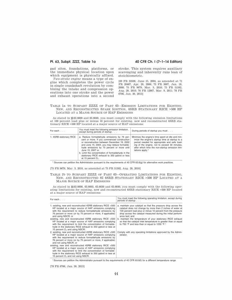
44
40 CFR Ch. I (7–1–14 Edition) Pt. 63, Subpt. ZZZZ, Table 1a
pad sites, foundations, platforms, or
the immediate physical location upon
which equipment is physically affixed.
Two-stroke engine means a type of en-
gine which completes the power cycle
in single crankshaft revolution by com-
bining the intake and compression op-
erations into one stroke and the power
and exhaust operations into a second
stroke. This system requires auxiliary
scavenging and inherently runs lean of
stoichiometric.
[69 FR 33506, June 15, 2004, as amended at 71
FR 20467, Apr. 20, 2006; 73 FR 3607, Jan. 18,
2008; 75 FR 9679, Mar. 3, 2010; 75 FR 51592,
Aug. 20, 2010; 76 FR 12867, Mar. 9, 2011; 78 FR
6706, Jan. 30, 2013]
TABLE 1a TO SUBPART ZZZZ OF PART 63—EMISSION LIMITATIONS FOR EXISTING,
NEW, AND RECONSTRUCTED SPARK IGNITION, 4SRB STATIONARY RICE >500 HP
LOCATED AT A MAJOR SOURCE OF HAP EMISSIONS
As stated in §§ 63.6600 and 63.6640, you must comply with the following emission limitations
at 100 percent load plus or minus 10 percent for existing, new and reconstructed 4SRB sta-
tionary RICE >500 HP located at a major source of HAP emissions:
For each . . . You must meet the following emission limitation, except during periods of startup . . . During periods of startup you must . . .
1. 4SRB stationary RICE a. Reduce formaldehyde emissions by 76 per-cent or more. If you commenced construction or reconstruction between December 19, 2002 and June 15, 2004, you may reduce formalde-hyde emissions by 75 percent or more until June 15, 2007 or.
Minimize the engine’s time spent at idle and min-imize the engine’s startup time at startup to a period needed for appropriate and safe load-ing of the engine, not to exceed 30 minutes, after which time the non-startup emission limi-tations apply.1
b. Limit the concentration of formaldehyde in the stationary RICE exhaust to 350 ppbvd or less at 15 percent O2.
1 Sources can petition the Administrator pursuant to the requirements of 40 CFR 63.6(g) for alternative work practices.
[75 FR 9679, Mar. 3, 2010, as amended at 75 FR 51592, Aug. 20, 2010]
TABLE 1b TO SUBPART ZZZZ OF PART 63—OPERATING LIMITATIONS FOR EXISTING,
NEW, AND RECONSTRUCTED SI 4SRB STATIONARY RICE >500 HP LOCATED AT A
MAJOR SOURCE OF HAP EMISSIONS
As stated in §§ 63.6600, 63.6603, 63.6630 and 63.6640, you must comply with the following oper-
ating limitations for existing, new and reconstructed 4SRB stationary RICE >500 HP located
at a major source of HAP emissions:
For each . . . You must meet the following operating limitation, except during periods of startup . . .
1. existing, new and reconstructed 4SRB stationary RICE >500 HP located at a major source of HAP emissions complying with the requirement to reduce formaldehyde emissions by 76 percent or more (or by 75 percent or more, if applicable) and using NSCR; or
existing, new and reconstructed 4SRB stationary RICE >500 HP located at a major source of HAP emissions complying with the requirement to limit the concentration of formalde-hyde in the stationary RICE exhaust to 350 ppbvd or less at 15 percent O2 and using NSCR;
a. maintain your catalyst so that the pressure drop across the catalyst does not change by more than 2 inches of water at 100 percent load plus or minus 10 percent from the pressure drop across the catalyst measured during the initial perform-ance test; and
b. maintain the temperature of your stationary RICE exhaust so that the catalyst inlet temperature is greater than or equal to 750 °F and less than or equal to 1250 °F.1
2. existing, new and reconstructed 4SRB stationary RICE >500 HP located at a major source of HAP emissions complying with the requirement to reduce formaldehyde emissions by 76 percent or more (or by 75 percent or more, if applicable) and not using NSCR; or
Comply with any operating limitations approved by the Admin-istrator.
existing, new and reconstructed 4SRB stationary RICE >500 HP located at a major source of HAP emissions complying with the requirement to limit the concentration of formalde-hyde in the stationary RICE exhaust to 350 ppbvd or less at 15 percent O2 and not using NSCR.
1 Sources can petition the Administrator pursuant to the requirements of 40 CFR 63.8(f) for a different temperature range.
[78 FR 6706, Jan. 30, 2013]
VerDate Sep<11>2014 13:42 Oct 28, 2014 Jkt 232162 PO 00000 Frm 00054 Fmt 8010 Sfmt 8026 Y:\SGML\232162.XXX 232162wre
ier-
avile
s on
DS
K5T
PT
VN
1PR
OD
with
CF
R
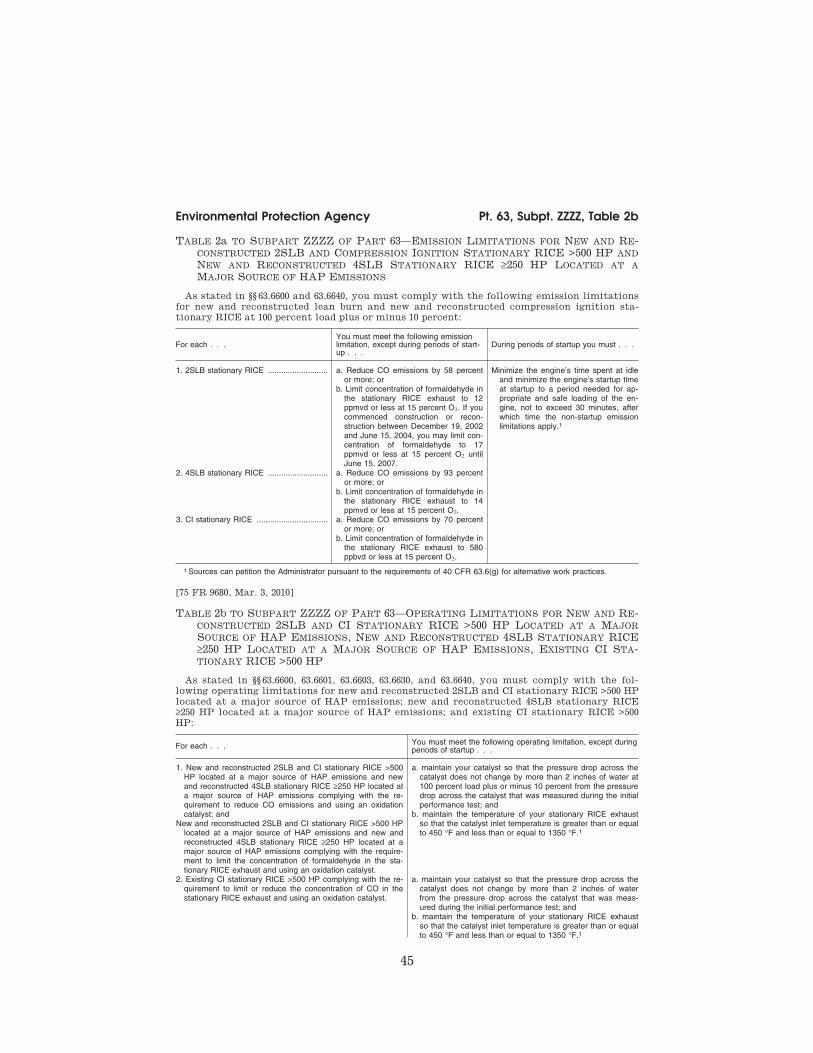
45
Environmental Protection Agency Pt. 63, Subpt. ZZZZ, Table 2b
TABLE 2a TO SUBPART ZZZZ OF PART 63—EMISSION LIMITATIONS FOR NEW AND RE-
CONSTRUCTED 2SLB AND COMPRESSION IGNITION STATIONARY RICE >500 HP AND
NEW AND RECONSTRUCTED 4SLB STATIONARY RICE ≥250 HP LOCATED AT A
MAJOR SOURCE OF HAP EMISSIONS
As stated in §§ 63.6600 and 63.6640, you must comply with the following emission limitations
for new and reconstructed lean burn and new and reconstructed compression ignition sta-
tionary RICE at 100 percent load plus or minus 10 percent:
For each . . . You must meet the following emission limitation, except during periods of start-up . . .
During periods of startup you must . . .
1. 2SLB stationary RICE ........................... a. Reduce CO emissions by 58 percent or more; or
b. Limit concentration of formaldehyde in the stationary RICE exhaust to 12 ppmvd or less at 15 percent O2. If you commenced construction or recon-struction between December 19, 2002 and June 15, 2004, you may limit con-centration of formaldehyde to 17 ppmvd or less at 15 percent O2 until June 15, 2007.
Minimize the engine’s time spent at idle and minimize the engine’s startup time at startup to a period needed for ap-propriate and safe loading of the en-gine, not to exceed 30 minutes, after which time the non-startup emission limitations apply.1
2. 4SLB stationary RICE ........................... a. Reduce CO emissions by 93 percent or more; or
b. Limit concentration of formaldehyde in the stationary RICE exhaust to 14 ppmvd or less at 15 percent O2.
3. CI stationary RICE ................................ a. Reduce CO emissions by 70 percent or more; or
b. Limit concentration of formaldehyde in the stationary RICE exhaust to 580 ppbvd or less at 15 percent O2.
1 Sources can petition the Administrator pursuant to the requirements of 40 CFR 63.6(g) for alternative work practices.
[75 FR 9680, Mar. 3, 2010]
TABLE 2b TO SUBPART ZZZZ OF PART 63—OPERATING LIMITATIONS FOR NEW AND RE-
CONSTRUCTED 2SLB AND CI STATIONARY RICE >500 HP LOCATED AT A MAJOR
SOURCE OF HAP EMISSIONS, NEW AND RECONSTRUCTED 4SLB STATIONARY RICE
≥250 HP LOCATED AT A MAJOR SOURCE OF HAP EMISSIONS, EXISTING CI STA-
TIONARY RICE >500 HP
As stated in §§ 63.6600, 63.6601, 63.6603, 63.6630, and 63.6640, you must comply with the fol-
lowing operating limitations for new and reconstructed 2SLB and CI stationary RICE >500 HP
located at a major source of HAP emissions; new and reconstructed 4SLB stationary RICE
≥250 HP located at a major source of HAP emissions; and existing CI stationary RICE >500
HP:
For each . . . You must meet the following operating limitation, except during periods of startup . . .
1. New and reconstructed 2SLB and CI stationary RICE >500 HP located at a major source of HAP emissions and new and reconstructed 4SLB stationary RICE ≥250 HP located at a major source of HAP emissions complying with the re-quirement to reduce CO emissions and using an oxidation catalyst; and
New and reconstructed 2SLB and CI stationary RICE >500 HP located at a major source of HAP emissions and new and reconstructed 4SLB stationary RICE ≥250 HP located at a major source of HAP emissions complying with the require-ment to limit the concentration of formaldehyde in the sta-tionary RICE exhaust and using an oxidation catalyst.
a. maintain your catalyst so that the pressure drop across the catalyst does not change by more than 2 inches of water at 100 percent load plus or minus 10 percent from the pressure drop across the catalyst that was measured during the initial performance test; and
b. maintain the temperature of your stationary RICE exhaust so that the catalyst inlet temperature is greater than or equal to 450 °F and less than or equal to 1350 °F.1
2. Existing CI stationary RICE >500 HP complying with the re-quirement to limit or reduce the concentration of CO in the stationary RICE exhaust and using an oxidation catalyst.
a. maintain your catalyst so that the pressure drop across the catalyst does not change by more than 2 inches of water from the pressure drop across the catalyst that was meas-ured during the initial performance test; and
b. maintain the temperature of your stationary RICE exhaust so that the catalyst inlet temperature is greater than or equal to 450 °F and less than or equal to 1350 °F.1
VerDate Sep<11>2014 13:42 Oct 28, 2014 Jkt 232162 PO 00000 Frm 00055 Fmt 8010 Sfmt 8002 Y:\SGML\232162.XXX 232162wre
ier-
avile
s on
DS
K5T
PT
VN
1PR
OD
with
CF
R
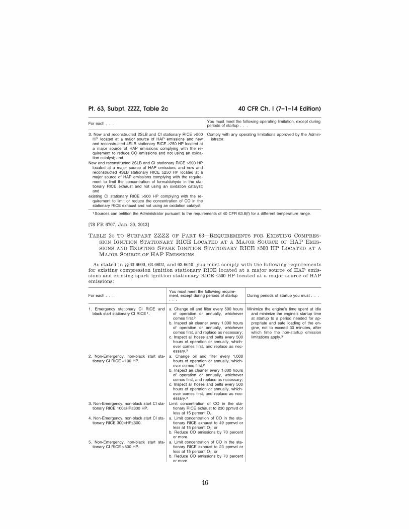
46
40 CFR Ch. I (7–1–14 Edition) Pt. 63, Subpt. ZZZZ, Table 2c
For each . . . You must meet the following operating limitation, except during periods of startup . . .
3. New and reconstructed 2SLB and CI stationary RICE >500 HP located at a major source of HAP emissions and new and reconstructed 4SLB stationary RICE ≥250 HP located at a major source of HAP emissions complying with the re-quirement to reduce CO emissions and not using an oxida-tion catalyst; and
Comply with any operating limitations approved by the Admin-istrator.
New and reconstructed 2SLB and CI stationary RICE >500 HP located at a major source of HAP emissions and new and reconstructed 4SLB stationary RICE ≥250 HP located at a major source of HAP emissions complying with the require-ment to limit the concentration of formaldehyde in the sta-tionary RICE exhaust and not using an oxidation catalyst; and
existing CI stationary RICE >500 HP complying with the re-quirement to limit or reduce the concentration of CO in the stationary RICE exhaust and not using an oxidation catalyst.
1 Sources can petition the Administrator pursuant to the requirements of 40 CFR 63.8(f) for a different temperature range.
[78 FR 6707, Jan. 30, 2013]
TABLE 2c TO SUBPART ZZZZ OF PART 63—REQUIREMENTS FOR EXISTING COMPRES-
SION IGNITION STATIONARY RICE LOCATED AT A MAJOR SOURCE OF HAP EMIS-
SIONS AND EXISTING SPARK IGNITION STATIONARY RICE ≤500 HP LOCATED AT A
MAJOR SOURCE OF HAP EMISSIONS
As stated in §§ 63.6600, 63.6602, and 63.6640, you must comply with the following requirements
for existing compression ignition stationary RICE located at a major source of HAP emis-
sions and existing spark ignition stationary RICE ≤500 HP located at a major source of HAP
emissions:
For each . . . You must meet the following require-ment, except during periods of startup . . .
During periods of startup you must . . .
1. Emergency stationary CI RICE and black start stationary CI RICE 1.
a. Change oil and filter every 500 hours of operation or annually, whichever comes first.2
b. Inspect air cleaner every 1,000 hours of operation or annually, whichever comes first, and replace as necessary;
c. Inspect all hoses and belts every 500 hours of operation or annually, which-ever comes first, and replace as nec-essary.3
Minimize the engine’s time spent at idle and minimize the engine’s startup time at startup to a period needed for ap-propriate and safe loading of the en-gine, not to exceed 30 minutes, after which time the non-startup emission limitations apply.3
2. Non-Emergency, non-black start sta-tionary CI RICE <100 HP.
a. Change oil and filter every 1,000 hours of operation or annually, which-ever comes first.2
b. Inspect air cleaner every 1,000 hours of operation or annually, whichever comes first, and replace as necessary;
c. Inspect all hoses and belts every 500 hours of operation or annually, which-ever comes first, and replace as nec-essary.3
3. Non-Emergency, non-black start CI sta-tionary RICE 100≤HP≤300 HP.
Limit concentration of CO in the sta-tionary RICE exhaust to 230 ppmvd or less at 15 percent O2.
4. Non-Emergency, non-black start CI sta-tionary RICE 300<HP≤500.
a. Limit concentration of CO in the sta-tionary RICE exhaust to 49 ppmvd or less at 15 percent O2; or
b. Reduce CO emissions by 70 percent or more.
5. Non-Emergency, non-black start sta-tionary CI RICE >500 HP.
a. Limit concentration of CO in the sta-tionary RICE exhaust to 23 ppmvd or less at 15 percent O2; or
b. Reduce CO emissions by 70 percent or more.
VerDate Sep<11>2014 13:42 Oct 28, 2014 Jkt 232162 PO 00000 Frm 00056 Fmt 8010 Sfmt 8002 Y:\SGML\232162.XXX 232162wre
ier-
avile
s on
DS
K5T
PT
VN
1PR
OD
with
CF
R

47
Environmental Protection Agency Pt. 63, Subpt. ZZZZ, Table 2c
For each . . . You must meet the following require-ment, except during periods of startup . . .
During periods of startup you must . . .
6. Emergency stationary SI RICE and black start stationary SI RICE.1
a. Change oil and filter every 500 hours of operation or annually, whichever comes first;2
b. Inspect spark plugs every 1,000 hours of operation or annually, whichever comes first, and replace as necessary;
c. Inspect all hoses and belts every 500 hours of operation or annually, which-ever comes first, and replace as nec-essary.3
7. Non-Emergency, non-black start sta-tionary SI RICE <100 HP that are not 2SLB stationary RICE.
a. Change oil and filter every 1,440 hours of operation or annually, which-ever comes first;2
b. Inspect spark plugs every 1,440 hours of operation or annually, whichever comes first, and replace as necessary;
c. Inspect all hoses and belts every 1,440 hours of operation or annually, whichever comes first, and replace as necessary.3
8. Non-Emergency, non-black start 2SLB stationary SI RICE <100 HP.
a. Change oil and filter every 4,320 hours of operation or annually, which-ever comes first;2
b. Inspect spark plugs every 4,320 hours of operation or annually, whichever comes first, and replace as necessary;
c. Inspect all hoses and belts every 4,320 hours of operation or annually, whichever comes first, and replace as necessary.3
9. Non-emergency, non-black start 2SLB stationary RICE 100≤HP≤500.
Limit concentration of CO in the sta-tionary RICE exhaust to 225 ppmvd or less at 15 percent O2.
10. Non-emergency, non-black start 4SLB stationary RICE 100≤HP≤500.
Limit concentration of CO in the sta-tionary RICE exhaust to 47 ppmvd or less at 15 percent O2.
11. Non-emergency, non-black start 4SRB stationary RICE 100≤HP≤500.
Limit concentration of formaldehyde in the stationary RICE exhaust to 10.3 ppmvd or less at 15 percent O2.
12. Non-emergency, non-black start sta-tionary RICE 100≤HP≤500 which com-busts landfill or digester gas equivalent to 10 percent or more of the gross heat input on an annual basis.
Limit concentration of CO in the sta-tionary RICE exhaust to 177 ppmvd or less at 15 percent O2.
1 If an emergency engine is operating during an emergency and it is not possible to shut down the engine in order to perform the work practice requirements on the schedule required in Table 2c of this subpart, or if performing the work practice on the re-quired schedule would otherwise pose an unacceptable risk under federal, state, or local law, the work practice can be delayed until the emergency is over or the unacceptable risk under federal, state, or local law has abated. The work practice should be performed as soon as practicable after the emergency has ended or the unacceptable risk under federal, state, or local law has abated. Sources must report any failure to perform the work practice on the schedule required and the federal, state or local law under which the risk was deemed unacceptable.
2 Sources have the option to utilize an oil analysis program as described in § 63.6625(i) or (j) in order to extend the specified oil change requirement in Table 2c of this subpart.
3 Sources can petition the Administrator pursuant to the requirements of 40 CFR 63.6(g) for alternative work practices.
[78 FR 6708, Jan. 30, 2013, as amended at 78 FR 14457, Mar. 6, 2013]
VerDate Sep<11>2014 13:42 Oct 28, 2014 Jkt 232162 PO 00000 Frm 00057 Fmt 8010 Sfmt 8026 Y:\SGML\232162.XXX 232162wre
ier-
avile
s on
DS
K5T
PT
VN
1PR
OD
with
CF
R

48
40 CFR Ch. I (7–1–14 Edition) Pt. 63, Subpt. ZZZZ, Table 2d
TABLE 2d TO SUBPART ZZZZ OF PART 63—REQUIREMENTS FOR EXISTING STATIONARY
RICE LOCATED AT AREA SOURCES OF HAP EMISSIONS
As stated in §§ 63.6603 and 63.6640, you must comply with the following requirements for ex-
isting stationary RICE located at area sources of HAP emissions:
For each . . . You must meet the following require-ment, except during periods of startup . . .
During periods of startup you must . . .
1. Non-Emergency, non-black start CI sta-tionary RICE ≤300 HP.
a. Change oil and filter every 1,000 hours of operation or annually, which-ever comes first;1
b. Inspect air cleaner every 1,000 hours of operation or annually, whichever comes first, and replace as necessary;
c. Inspect all hoses and belts every 500 hours of operation or annually, which-ever comes first, and replace as nec-essary.
Minimize the engine’s time spent at idle and minimize the engine’s startup time at startup to a period needed for ap-propriate and safe loading of the en-gine, not to exceed 30 minutes, after which time the non-startup emission limitations apply.
2. Non-Emergency, non-black start CI sta-tionary RICE 300<HP≤500.
a. Limit concentration of CO in the sta-tionary RICE exhaust to 49 ppmvd at 15 percent O2; or
b. Reduce CO emissions by 70 percent or more.
3. Non-Emergency, non-black start CI sta-tionary RICE >500 HP.
a. Limit concentration of CO in the sta-tionary RICE exhaust to 23 ppmvd at 15 percent O2; or
b. Reduce CO emissions by 70 percent or more.
4. Emergency stationary CI RICE and black start stationary CI RICE.2
a. Change oil and filter every 500 hours of operation or annually, whichever comes first;1
b. Inspect air cleaner every 1,000 hours of operation or annually, whichever comes first, and replace as necessary; and
c. Inspect all hoses and belts every 500 hours of operation or annually, which-ever comes first, and replace as nec-essary.
5. Emergency stationary SI RICE; black start stationary SI RICE; non-emer-gency, non-black start 4SLB stationary RICE >500 HP that operate 24 hours or less per calendar year; non-emergency, non-black start 4SRB stationary RICE >500 HP that operate 24 hours or less per calendar year.2
a. Change oil and filter every 500 hours of operation or annually, whichever comes first;1;
b. Inspect spark plugs every 1,000 hours of operation or annually, whichever comes first, and replace as necessary; and
c. Inspect all hoses and belts every 500 hours of operation or annually, which-ever comes first, and replace as nec-essary.
6. Non-emergency, non-black start 2SLB stationary RICE.
a. Change oil and filter every 4,320 hours of operation or annually, which-ever comes first;1
b. Inspect spark plugs every 4,320 hours of operation or annually, whichever comes first, and replace as necessary; and
c. Inspect all hoses and belts every 4,320 hours of operation or annually, whichever comes first, and replace as necessary.
7. Non-emergency, non-black start 4SLB stationary RICE ≤500 HP.
a. Change oil and filter every 1,440 hours of operation or annually, which-ever comes first;1
b. Inspect spark plugs every 1,440 hours of operation or annually, whichever comes first, and replace as necessary; and
c. Inspect all hoses and belts every 1,440 hours of operation or annually, whichever comes first, and replace as necessary.
VerDate Sep<11>2014 13:42 Oct 28, 2014 Jkt 232162 PO 00000 Frm 00058 Fmt 8010 Sfmt 8002 Y:\SGML\232162.XXX 232162wre
ier-
avile
s on
DS
K5T
PT
VN
1PR
OD
with
CF
R

49
Environmental Protection Agency Pt. 63, Subpt. ZZZZ, Table 2d
For each . . . You must meet the following require-ment, except during periods of startup . . .
During periods of startup you must . . .
8. Non-emergency, non-black start 4SLB remote stationary RICE >500 HP.
a. Change oil and filter every 2,160 hours of operation or annually, which-ever comes first;1
b. Inspect spark plugs every 2,160 hours of operation or annually, whichever comes first, and replace as necessary; and
c. Inspect all hoses and belts every 2,160 hours of operation or annually, whichever comes first, and replace as necessary.
9. Non-emergency, non-black start 4SLB stationary RICE >500 HP that are not remote stationary RICE and that oper-ate more than 24 hours per calendar year.
Install an oxidation catalyst to reduce HAP emissions from the stationary RICE.
10. Non-emergency, non-black start 4SRB stationary RICE ≤500 HP.
a. Change oil and filter every 1,440 hours of operation or annually, which-ever comes first;1
b. Inspect spark plugs every 1,440 hours of operation or annually, whichever comes first, and replace as necessary; and
c. Inspect all hoses and belts every 1,440 hours of operation or annually, whichever comes first, and replace as necessary.
11. Non-emergency, non-black start 4SRB remote stationary RICE >500 HP.
a. Change oil and filter every 2,160 hours of operation or annually, which-ever comes first;1
b. Inspect spark plugs every 2,160 hours of operation or annually, whichever comes first, and replace as necessary; and
c. Inspect all hoses and belts every 2,160 hours of operation or annually, whichever comes first, and replace as necessary.
12. Non-emergency, non-black start 4SRB stationary RICE >500 HP that are not remote stationary RICE and that oper-ate more than 24 hours per calendar year.
Install NSCR to reduce HAP emissions from the stationary RICE.
13. Non-emergency, non-black start sta-tionary RICE which combusts landfill or digester gas equivalent to 10 percent or more of the gross heat input on an an-nual basis.
a. Change oil and filter every 1,440 hours of operation or annually, which-ever comes first;1
b. Inspect spark plugs every 1,440 hours of operation or annually, whichever comes first, and replace as necessary; and
c. Inspect all hoses and belts every 1,440 hours of operation or annually, whichever comes first, and replace as necessary.
1 Sources have the option to utilize an oil analysis program as described in § 63.6625(i) or (j) in order to extend the specified oil change requirement in Table 2d of this subpart.
2 If an emergency engine is operating during an emergency and it is not possible to shut down the engine in order to perform the management practice requirements on the schedule required in Table 2d of this subpart, or if performing the management practice on the required schedule would otherwise pose an unacceptable risk under federal, state, or local law, the management practice can be delayed until the emergency is over or the unacceptable risk under federal, state, or local law has abated. The management practice should be performed as soon as practicable after the emergency has ended or the unacceptable risk under federal, state, or local law has abated. Sources must report any failure to perform the management practice on the sched-ule required and the federal, state or local law under which the risk was deemed unacceptable.
[78 FR 6709, Jan. 30, 2013]
VerDate Sep<11>2014 13:42 Oct 28, 2014 Jkt 232162 PO 00000 Frm 00059 Fmt 8010 Sfmt 8026 Y:\SGML\232162.XXX 232162wre
ier-
avile
s on
DS
K5T
PT
VN
1PR
OD
with
CF
R

50
40 CFR Ch. I (7–1–14 Edition) Pt. 63, Subpt. ZZZZ, Table 3
TABLE 3 TO SUBPART ZZZZ OF PART 63—SUBSEQUENT PERFORMANCE TESTS
As stated in §§ 63.6615 and 63.6620, you must comply with the following subsequent perform-
ance test requirements:
For each . . . Complying with the requirement to . . . You must . . .
1. New or reconstructed 2SLB stationary RICE >500 HP located at major sources; new or reconstructed 4SLB stationary RICE ≥250 HP located at major sources; and new or recon-structed CI stationary RICE >500 HP located at major sources.
Reduce CO emissions and not using a CEMS.
Conduct subsequent performance tests semiannually.1
2. 4SRB stationary RICE ≥5,000 HP lo-cated at major sources.
Reduce formaldehyde emissions ............ Conduct subsequent performance tests semiannually.1
3. Stationary RICE >500 HP located at major sources and new or recon-structed 4SLB stationary RICE 250≤HP≤500 located at major sources.
Limit the concentration of formaldehyde in the stationary RICE exhaust.
Conduct subsequent performance tests semiannually.1
4. Existing non-emergency, non-black start CI stationary RICE >500 HP that are not limited use stationary RICE.
Limit or reduce CO emissions and not using a CEMS.
Conduct subsequent performance tests every 8,760 hours or 3 years, which-ever comes first.
5. Existing non-emergency, non-black start CI stationary RICE >500 HP that are limited use stationary RICE.
Limit or reduce CO emissions and not using a CEMS.
Conduct subsequent performance tests every 8,760 hours or 5 years, which-ever comes first.
1 After you have demonstrated compliance for two consecutive tests, you may reduce the frequency of subsequent perform-ance tests to annually. If the results of any subsequent annual performance test indicate the stationary RICE is not in compliance with the CO or formaldehyde emission limitation, or you deviate from any of your operating limitations, you must resume semi-annual performance tests.
[78 FR 6711, Jan. 30, 2013]
TABLE 4 TO SUBPART ZZZZ OF PART 63—REQUIREMENTS FOR PERFORMANCE TESTS
As stated in §§ 63.6610, 63.6611, 63.6620, and 63.6640, you must comply with the following re-
quirements for performance tests for stationary RICE:
TABLE 4 TO SUBPART ZZZZ OF PART 63—REQUIREMENTS FOR PERFORMANCE TESTS
For each . . . Complying with the requirement to . . . You must . . . Using . . . According to the
following requirements . . .
1. 2SLB, 4SLB, and CI sta-tionary RICE.
a. reduce CO emis-sions.
i. Select the sam-pling port location and the number/ location of tra-verse points at the inlet and out-let of the control device; and
................................. (a) For CO and O2 measurement, ducts ≤6 inches in diameter may be sam-pled at a single point located at the duct centroid and ducts >6 and ≤12 inches in diameter may be sampled at 3 traverse points located at 16.7, 50.0, and 83.3% of the measurement line (‘3-point long line’). If the duct is >12 inches in diameter and the sampling port location meets the two and half- diameter criterion of Section 11.1.1 of Method 1 of 40 CFR part 60, appendix A–1, the duct may be sampled at ‘3- point long line’; otherwise, conduct the stratification testing and select sam-pling points according to Section 8.1.2 of Method 7E of 40 CFR part 60, ap-pendix A–4.
ii. Measure the O2 at the inlet and outlet of the con-trol device; and
(1) Method 3 or 3A or 3B of 40 CFR part 60, appendix A–2, or ASTM Method D6522– 00 (Reapproved 2005)a c (heated probe not nec-essary).
(b) Measurements to determine O2 must be made at the same time as the measurements for CO concentration.
VerDate Sep<11>2014 13:42 Oct 28, 2014 Jkt 232162 PO 00000 Frm 00060 Fmt 8010 Sfmt 8026 Y:\SGML\232162.XXX 232162wre
ier-
avile
s on
DS
K5T
PT
VN
1PR
OD
with
CF
R

51
Environmental Protection Agency Pt. 63, Subpt. ZZZZ, Table 4
TABLE 4 TO SUBPART ZZZZ OF PART 63—REQUIREMENTS FOR PERFORMANCE TESTS—Continued
For each . . . Complying with the requirement to . . . You must . . . Using . . . According to the
following requirements . . .
iii. Measure the CO at the inlet and the outlet of the control device.
(1) ASTM D6522– 00 (Reapproved 2005)a b c (heated probe not nec-essary) or Method 10 of 40 CFR part 60, appendix A–4.
(c) The CO concentration must be at 15 percent O2, dry basis.
2. 4SRB sta-tionary RICE.
a. reduce formalde-hyde emissions.
i. Select the sam-pling port location and the number/ location of tra-verse points at the inlet and out-let of the control device; and
................................. (a) For formaldehyde, O2, and moisture measurement, ducts ≤6 inches in di-ameter may be sampled at a single point located at the duct centroid and ducts >6 and ≤12 inches in diameter may be sampled at 3 traverse points located at 16.7, 50.0, and 83.3% of the measurement line (‘3-point long line’). If the duct is >12 inches in di-ameter and the sampling port location meets the two and half-diameter cri-terion of Section 11.1.1 of Method 1 of 40 CFR part 60, appendix A, the duct may be sampled at ‘3-point long line’; otherwise, conduct the stratification testing and select sampling points ac-cording to Section 8.1.2 of Method 7E of 40 CFR part 60, appendix A.
ii. Measure O2 at the inlet and out-let of the control device; and
(1) Method 3 or 3A or 3B of 40 CFR part 60, appendix A–2, or ASTM Method D6522– 00 (Reapproved 2005) a (heated probe not nec-essary).
(a) Measurements to determine O2 con-centration must be made at the same time as the measurements for form-aldehyde or THC concentration.
iii. Measure mois-ture content at the inlet and outlet of the control device; and
(1) Method 4 of 40 CFR part 60, ap-pendix A–3, or Method 320 of 40 CFR part 63, ap-pendix A, or ASTM D 6348– 03 a.
(a) Measurements to determine moisture content must be made at the same time and location as the measure-ments for formaldehyde or THC con-centration.
iv. If demonstrating compliance with the formaldehyde percent reduction requirement, measure formalde-hyde at the inlet and the outlet of the con-trol device.
(1) Method 320 or 323 of 40 CFR part 63, appendix A; or ASTM D6348–03 a, pro-vided in ASTM D6348–03 Annex A5 (Analyte Spik-ing Technique), the percent R must be greater than or equal to 70 and less than or equal to 130.
(a) Formaldehyde concentration must be at 15 percent O2, dry basis. Results of this test consist of the average of the three 1-hour or longer runs.
v. If demonstrating compliance with the THC percent reduction require-ment, measure THC at the inlet and the outlet of the control device.
(1) Method 25A, re-ported as pro-pane, of 40 CFR part 60, appendix A–7.
(a) THC concentration must be at 15 percent O2, dry basis. Results of this test consist of the average of the three 1-hour or longer runs.
VerDate Sep<11>2014 13:42 Oct 28, 2014 Jkt 232162 PO 00000 Frm 00061 Fmt 8010 Sfmt 8026 Y:\SGML\232162.XXX 232162wre
ier-
avile
s on
DS
K5T
PT
VN
1PR
OD
with
CF
R

52
40 CFR Ch. I (7–1–14 Edition) Pt. 63, Subpt. ZZZZ, Table 4
TABLE 4 TO SUBPART ZZZZ OF PART 63—REQUIREMENTS FOR PERFORMANCE TESTS—Continued
For each . . . Complying with the requirement to . . . You must . . . Using . . . According to the
following requirements . . .
3. Stationary RICE.
a. limit the concentra- tion of formalde- hyde or CO in the sta-tionary RICE ex-haust.
i. Select the sam-pling port location and the number/ location of tra-verse points at the exhaust of the stationary RICE; and
................................. (a) For formaldehyde, CO, O2, and mois-ture measurement, ducts ≤6 inches in diameter may be sampled at a single point located at the duct centroid and ducts >6 and ≤12 inches in diameter may be sampled at 3 traverse points located at 16.7, 50.0, and 83.3% of the measurement line (‘3-point long line’). If the duct is >12 inches in di-ameter and the sampling port location meets the two and half-diameter cri-terion of Section 11.1.1 of Method 1 of 40 CFR part 60, appendix A, the duct may be sampled at ‘3-point long line’; otherwise, conduct the stratification testing and select sampling points ac-cording to Section 8.1.2 of Method 7E of 40 CFR part 60, appendix A. If using a control device, the sampling site must be located at the outlet of the control device.
ii. Determine the O2 concentration of the stationary RICE exhaust at the sampling port location; and
(1) Method 3 or 3A or 3B of 40 CFR part 60, appendix A–2, or ASTM Method D6522– 00 (Reapproved 2005) a (heated probe not nec-essary).
(a) Measurements to determine O2 con-centration must be made at the same time and location as the measure-ments for formaldehyde or CO con-centration.
iii. Measure mois-ture content of the stationary RICE exhaust at the sampling port lo-cation; and
(1) Method 4 of 40 CFR part 60, ap-pendix A–3, or Method 320 of 40 CFR part 63, ap-pendix A, or ASTM D 6348– 03 a.
(a) Measurements to determine moisture content must be made at the same time and location as the measure-ments for formaldehyde or CO con-centration.
iv. Measure formalde-hyde at the exhaust of the stationary RICE; or
(1) Method 320 or 323 of 40 CFR part 63, appendix A; or ASTM D6348–03 a, pro-vided in ASTM D6348–03 Annex A5 (Analyte Spik-ing Technique), the percent R must be greater than or equal to 70 and less than or equal to 130.
(a) Formaldehyde concentration must be at 15 percent O2, dry basis. Results of this test consist of the average of the three 1-hour or longer runs.
v. measure CO at the exhaust of the station-ary RICE.
(1) Method 10 of 40 CFR part 60, ap-pendix A–4, ASTM Method D6522–00 (2005) a c, Method 320 of 40 CFR part 63, appendix A, or ASTM D6348–03 a.
(a) CO concentration must be at 15 per-cent O2, dry basis. Results of this test consist of the average of the three 1- hour or longer runs.
a You may also use Methods 3A and 10 as options to ASTM–D6522–00 (2005). You may obtain a copy of ASTM–D6522–00 (2005) from at least one of the following addresses: American Society for Testing and Materials, 100 Barr Harbor Drive, West Conshohocken, PA 19428–2959, or University Microfilms International, 300 North Zeeb Road, Ann Arbor, MI 48106.
b You may obtain a copy of ASTM–D6348–03 from at least one of the following addresses: American Society for Testing and Materials, 100 Barr Harbor Drive, West Conshohocken, PA 19428–2959, or University Microfilms International, 300 North Zeeb Road, Ann Arbor, MI 48106.
[79 FR 11290, Feb. 27, 2014]
VerDate Sep<11>2014 13:42 Oct 28, 2014 Jkt 232162 PO 00000 Frm 00062 Fmt 8010 Sfmt 8026 Y:\SGML\232162.XXX 232162wre
ier-
avile
s on
DS
K5T
PT
VN
1PR
OD
with
CF
R
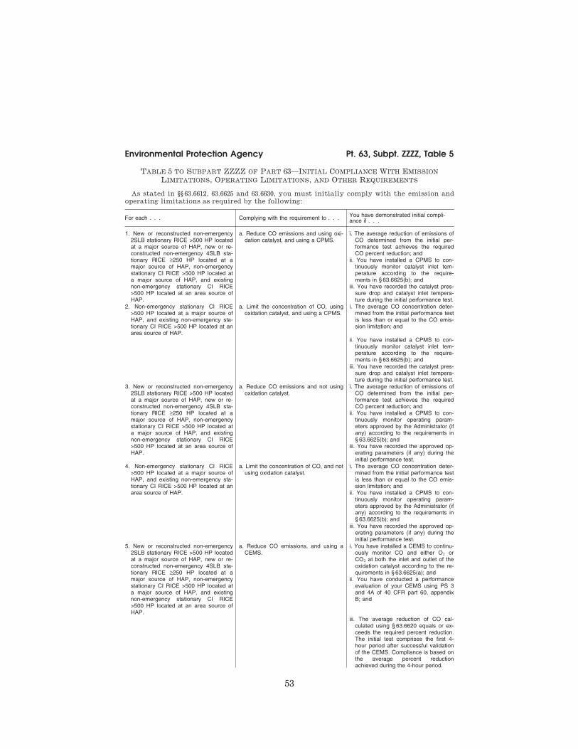
53
Environmental Protection Agency Pt. 63, Subpt. ZZZZ, Table 5
TABLE 5 TO SUBPART ZZZZ OF PART 63—INITIAL COMPLIANCE WITH EMISSION
LIMITATIONS, OPERATING LIMITATIONS, AND OTHER REQUIREMENTS
As stated in §§ 63.6612, 63.6625 and 63.6630, you must initially comply with the emission and
operating limitations as required by the following:
For each . . . Complying with the requirement to . . . You have demonstrated initial compli-ance if . . .
1. New or reconstructed non-emergency 2SLB stationary RICE >500 HP located at a major source of HAP, new or re-constructed non-emergency 4SLB sta-tionary RICE ≥250 HP located at a major source of HAP, non-emergency stationary CI RICE >500 HP located at a major source of HAP, and existing non-emergency stationary CI RICE >500 HP located at an area source of HAP.
a. Reduce CO emissions and using oxi-dation catalyst, and using a CPMS.
i. The average reduction of emissions of CO determined from the initial per-formance test achieves the required CO percent reduction; and
ii. You have installed a CPMS to con-tinuously monitor catalyst inlet tem-perature according to the require-ments in § 63.6625(b); and
iii. You have recorded the catalyst pres-sure drop and catalyst inlet tempera-ture during the initial performance test.
2. Non-emergency stationary CI RICE >500 HP located at a major source of HAP, and existing non-emergency sta-tionary CI RICE >500 HP located at an area source of HAP.
a. Limit the concentration of CO, using oxidation catalyst, and using a CPMS.
i. The average CO concentration deter-mined from the initial performance test is less than or equal to the CO emis-sion limitation; and
ii. You have installed a CPMS to con-tinuously monitor catalyst inlet tem-perature according to the require-ments in § 63.6625(b); and
iii. You have recorded the catalyst pres-sure drop and catalyst inlet tempera-ture during the initial performance test.
3. New or reconstructed non-emergency 2SLB stationary RICE >500 HP located at a major source of HAP, new or re-constructed non-emergency 4SLB sta-tionary RICE ≥250 HP located at a major source of HAP, non-emergency stationary CI RICE >500 HP located at a major source of HAP, and existing non-emergency stationary CI RICE >500 HP located at an area source of HAP.
a. Reduce CO emissions and not using oxidation catalyst.
i. The average reduction of emissions of CO determined from the initial per-formance test achieves the required CO percent reduction; and
ii. You have installed a CPMS to con-tinuously monitor operating param-eters approved by the Administrator (if any) according to the requirements in § 63.6625(b); and
iii. You have recorded the approved op-erating parameters (if any) during the initial performance test.
4. Non-emergency stationary CI RICE >500 HP located at a major source of HAP, and existing non-emergency sta-tionary CI RICE >500 HP located at an area source of HAP.
a. Limit the concentration of CO, and not using oxidation catalyst.
i. The average CO concentration deter-mined from the initial performance test is less than or equal to the CO emis-sion limitation; and
ii. You have installed a CPMS to con-tinuously monitor operating param-eters approved by the Administrator (if any) according to the requirements in § 63.6625(b); and
iii. You have recorded the approved op-erating parameters (if any) during the initial performance test.
5. New or reconstructed non-emergency 2SLB stationary RICE >500 HP located at a major source of HAP, new or re-constructed non-emergency 4SLB sta-tionary RICE ≥250 HP located at a major source of HAP, non-emergency stationary CI RICE >500 HP located at a major source of HAP, and existing non-emergency stationary CI RICE >500 HP located at an area source of HAP.
a. Reduce CO emissions, and using a CEMS.
i. You have installed a CEMS to continu-ously monitor CO and either O2 or CO2 at both the inlet and outlet of the oxidation catalyst according to the re-quirements in § 63.6625(a); and
ii. You have conducted a performance evaluation of your CEMS using PS 3 and 4A of 40 CFR part 60, appendix B; and
iii. The average reduction of CO cal-culated using § 63.6620 equals or ex-ceeds the required percent reduction. The initial test comprises the first 4- hour period after successful validation of the CEMS. Compliance is based on the average percent reduction achieved during the 4-hour period.
VerDate Sep<11>2014 13:42 Oct 28, 2014 Jkt 232162 PO 00000 Frm 00063 Fmt 8010 Sfmt 8002 Y:\SGML\232162.XXX 232162wre
ier-
avile
s on
DS
K5T
PT
VN
1PR
OD
with
CF
R
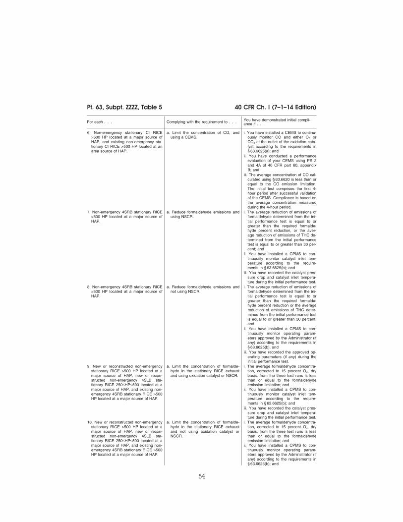
54
40 CFR Ch. I (7–1–14 Edition) Pt. 63, Subpt. ZZZZ, Table 5
For each . . . Complying with the requirement to . . . You have demonstrated initial compli-ance if . . .
6. Non-emergency stationary CI RICE >500 HP located at a major source of HAP, and existing non-emergency sta-tionary CI RICE >500 HP located at an area source of HAP.
a. Limit the concentration of CO, and using a CEMS.
i. You have installed a CEMS to continu-ously monitor CO and either O2 or CO2 at the outlet of the oxidation cata-lyst according to the requirements in § 63.6625(a); and
ii. You have conducted a performance evaluation of your CEMS using PS 3 and 4A of 40 CFR part 60, appendix B; and
iii. The average concentration of CO cal-culated using § 63.6620 is less than or equal to the CO emission limitation. The initial test comprises the first 4- hour period after successful validation of the CEMS. Compliance is based on the average concentration measured during the 4-hour period.
7. Non-emergency 4SRB stationary RICE >500 HP located at a major source of HAP.
a. Reduce formaldehyde emissions and using NSCR.
i. The average reduction of emissions of formaldehyde determined from the ini-tial performance test is equal to or greater than the required formalde-hyde percent reduction, or the aver-age reduction of emissions of THC de-termined from the initial performance test is equal to or greater than 30 per-cent; and
ii. You have installed a CPMS to con-tinuously monitor catalyst inlet tem-perature according to the require-ments in § 63.6625(b); and
iii. You have recorded the catalyst pres-sure drop and catalyst inlet tempera-ture during the initial performance test.
8. Non-emergency 4SRB stationary RICE >500 HP located at a major source of HAP.
a. Reduce formaldehyde emissions and not using NSCR.
i. The average reduction of emissions of formaldehyde determined from the ini-tial performance test is equal to or greater than the required formalde-hyde percent reduction or the average reduction of emissions of THC deter-mined from the initial performance test is equal to or greater than 30 percent; and
ii. You have installed a CPMS to con-tinuously monitor operating param-eters approved by the Administrator (if any) according to the requirements in § 63.6625(b); and
iii. You have recorded the approved op-erating parameters (if any) during the initial performance test.
9. New or reconstructed non-emergency stationary RICE >500 HP located at a major source of HAP, new or recon-structed non-emergency 4SLB sta-tionary RICE 250≤HP≤500 located at a major source of HAP, and existing non- emergency 4SRB stationary RICE >500 HP located at a major source of HAP.
a. Limit the concentration of formalde-hyde in the stationary RICE exhaust and using oxidation catalyst or NSCR.
i. The average formaldehyde concentra-tion, corrected to 15 percent O2, dry basis, from the three test runs is less than or equal to the formaldehyde emission limitation; and
ii. You have installed a CPMS to con-tinuously monitor catalyst inlet tem-perature according to the require-ments in § 63.6625(b); and
iii. You have recorded the catalyst pres-sure drop and catalyst inlet tempera-ture during the initial performance test.
10. New or reconstructed non-emergency stationary RICE >500 HP located at a major source of HAP, new or recon-structed non-emergency 4SLB sta-tionary RICE 250≤HP≤500 located at a major source of HAP, and existing non- emergency 4SRB stationary RICE >500 HP located at a major source of HAP.
a. Limit the concentration of formalde-hyde in the stationary RICE exhaust and not using oxidation catalyst or NSCR.
i. The average formaldehyde concentra-tion, corrected to 15 percent O2, dry basis, from the three test runs is less than or equal to the formaldehyde emission limitation; and
ii. You have installed a CPMS to con-tinuously monitor operating param-eters approved by the Administrator (if any) according to the requirements in § 63.6625(b); and
VerDate Sep<11>2014 13:42 Oct 28, 2014 Jkt 232162 PO 00000 Frm 00064 Fmt 8010 Sfmt 8002 Y:\SGML\232162.XXX 232162wre
ier-
avile
s on
DS
K5T
PT
VN
1PR
OD
with
CF
R

55
Environmental Protection Agency Pt. 63, Subpt. ZZZZ, Table 5
For each . . . Complying with the requirement to . . . You have demonstrated initial compli-ance if . . .
iii. You have recorded the approved op-erating parameters (if any) during the initial performance test.
11. Existing non-emergency stationary RICE 100≤HP≤500 located at a major source of HAP, and existing non-emer-gency stationary CI RICE 300<HP≤500 located at an area source of HAP.
a. Reduce CO emissions ........................ i. The average reduction of emissions of CO or formaldehyde, as applicable de-termined from the initial performance test is equal to or greater than the re-quired CO or formaldehyde, as appli-cable, percent reduction.
12. Existing non-emergency stationary RICE 100≤HP≤500 located at a major source of HAP, and existing non-emer-gency stationary CI RICE 300<HP≤500 located at an area source of HAP.
a. Limit the concentration of formalde-hyde or CO in the stationary RICE ex-haust.
i. The average formaldehyde or CO con-centration, as applicable, corrected to 15 percent O2, dry basis, from the three test runs is less than or equal to the formaldehyde or CO emission limi-tation, as applicable.
13. Existing non-emergency 4SLB sta-tionary RICE >500 HP located at an area source of HAP that are not remote stationary RICE and that are operated more than 24 hours per calendar year.
a. Install an oxidation catalyst ................. i. You have conducted an initial compli-ance demonstration as specified in § 63.6630(e) to show that the average reduction of emissions of CO is 93 percent or more, or the average CO concentration is less than or equal to 47 ppmvd at 15 percent O2;
ii. You have installed a CPMS to con-tinuously monitor catalyst inlet tem-perature according to the require-ments in § 63.6625(b), or you have in-stalled equipment to automatically shut down the engine if the catalyst inlet temperature exceeds 1350 °F.
14. Existing non-emergency 4SRB sta-tionary RICE >500 HP located at an area source of HAP that are not remote stationary RICE and that are operated more than 24 hours per calendar year.
a. Install NSCR ........................................ i. You have conducted an initial compli-ance demonstration as specified in § 63.6630(e) to show that the average reduction of emissions of CO is 75 percent or more, the average CO con-centration is less than or equal to 270 ppmvd at 15 percent O2, or the aver-age reduction of emissions of THC is 30 percent or more;
ii. You have installed a CPMS to con-tinuously monitor catalyst inlet tem-perature according to the require-ments in § 63.6625(b), or you have in-stalled equipment to automatically shut down the engine if the catalyst inlet temperature exceeds 1250 °F.
[78 FR 6712, Jan. 30, 2013]
VerDate Sep<11>2014 13:42 Oct 28, 2014 Jkt 232162 PO 00000 Frm 00065 Fmt 8010 Sfmt 8026 Y:\SGML\232162.XXX 232162wre
ier-
avile
s on
DS
K5T
PT
VN
1PR
OD
with
CF
R

56
40 CFR Ch. I (7–1–14 Edition) Pt. 63, Subpt. ZZZZ, Table 6
TABLE 6 TO SUBPART ZZZZ OF PART 63—CONTINUOUS COMPLIANCE WITH EMISSION
LIMITATIONS, AND OTHER REQUIREMENTS
As stated in § 63.6640, you must continuously comply with the emissions and operating limi-
tations and work or management practices as required by the following:
For each . . . Complying with the requirement to . . . You must demonstrate continuous com-pliance by . . .
1. New or reconstructed non-emergency 2SLB stationary RICE >500 HP located at a major source of HAP, new or re-constructed non-emergency 4SLB sta-tionary RICE ≥250 HP located at a major source of HAP, and new or re-constructed non-emergency CI sta-tionary RICE >500 HP located at a major source of HAP.
a. Reduce CO emissions and using an oxidation catalyst, and using a CPMS.
i. Conducting semiannual performance tests for CO to demonstrate that the required CO percent reduction is achieved a; and
ii. Collecting the catalyst inlet tempera-ture data according to § 63.6625(b); and
iii. Reducing these data to 4-hour rolling averages; and
iv. Maintaining the 4-hour rolling aver-ages within the operating limitations for the catalyst inlet temperature; and
v. Measuring the pressure drop across the catalyst once per month and dem-onstrating that the pressure drop across the catalyst is within the oper-ating limitation established during the performance test.
2. New or reconstructed non-emergency 2SLB stationary RICE >500 HP located at a major source of HAP, new or re-constructed non-emergency 4SLB sta-tionary RICE ≥250 HP located at a major source of HAP, and new or re-constructed non-emergency CI sta-tionary RICE >500 HP located at a major source of HAP.
a. Reduce CO emissions and not using an oxidation catalyst, and using a CPMS.
i. Conducting semiannual performance tests for CO to demonstrate that the required CO percent reduction is achieved a; and
ii. Collecting the approved operating pa-rameter (if any) data according to § 63.6625(b); and
iii. Reducing these data to 4-hour rolling averages; and
iv. Maintaining the 4-hour rolling aver-ages within the operating limitations for the operating parameters estab-lished during the performance test.
3. New or reconstructed non-emergency 2SLB stationary RICE >500 HP located at a major source of HAP, new or re-constructed non-emergency 4SLB sta-tionary RICE ≥250 HP located at a major source of HAP, new or recon-structed non-emergency stationary CI RICE >500 HP located at a major source of HAP, and existing non-emer-gency stationary CI RICE >500 HP.
a. Reduce CO emissions or limit the concentration of CO in the stationary RICE exhaust, and using a CEMS.
i. Collecting the monitoring data accord-ing to § 63.6625(a), reducing the measurements to 1-hour averages, calculating the percent reduction or concentration of CO emissions ac-cording to § 63.6620; and
ii. Demonstrating that the catalyst achieves the required percent reduc-tion of CO emissions over the 4-hour averaging period, or that the emission remain at or below the CO concentra-tion limit; and
iii. Conducting an annual RATA of your CEMS using PS 3 and 4A of 40 CFR part 60, appendix B, as well as daily and periodic data quality checks in ac-cordance with 40 CFR part 60, appen-dix F, procedure 1.
4. Non-emergency 4SRB stationary RICE >500 HP located at a major source of HAP.
a. Reduce formaldehyde emissions and using NSCR.
i. Collecting the catalyst inlet tempera-ture data according to § 63.6625(b); and
ii. Reducing these data to 4-hour rolling averages; and
iii. Maintaining the 4-hour rolling aver-ages within the operating limitations for the catalyst inlet temperature; and
iv. Measuring the pressure drop across the catalyst once per month and dem-onstrating that the pressure drop across the catalyst is within the oper-ating limitation established during the performance test.
5. Non-emergency 4SRB stationary RICE >500 HP located at a major source of HAP.
a. Reduce formaldehyde emissions and not using NSCR.
i. Collecting the approved operating pa-rameter (if any) data according to § 63.6625(b); and
VerDate Sep<11>2014 13:42 Oct 28, 2014 Jkt 232162 PO 00000 Frm 00066 Fmt 8010 Sfmt 8002 Y:\SGML\232162.XXX 232162wre
ier-
avile
s on
DS
K5T
PT
VN
1PR
OD
with
CF
R

57
Environmental Protection Agency Pt. 63, Subpt. ZZZZ, Table 6
For each . . . Complying with the requirement to . . . You must demonstrate continuous com-pliance by . . .
ii. Reducing these data to 4-hour rolling averages; and
iii. Maintaining the 4-hour rolling aver-ages within the operating limitations for the operating parameters estab-lished during the performance test.
6. Non-emergency 4SRB stationary RICE with a brake HP ≥5,000 located at a major source of HAP.
a. Reduce formaldehyde emissions ........ Conducting semiannual performance tests for formaldehyde to demonstrate that the required formaldehyde per-cent reduction is achieved, or to dem-onstrate that the average reduction of emissions of THC determined from the performance test is equal to or greater than 30 percent.a
7. New or reconstructed non-emergency stationary RICE >500 HP located at a major source of HAP and new or recon-structed non-emergency 4SLB sta-tionary RICE 250≤HP≤500 located at a major source of HAP.
a. Limit the concentration of formalde-hyde in the stationary RICE exhaust and using oxidation catalyst or NSCR.
i. Conducting semiannual performance tests for formaldehyde to demonstrate that your emissions remain at or below the formaldehyde concentration limit a; and
ii. Collecting the catalyst inlet tempera-ture data according to § 63.6625(b); and
iii. Reducing these data to 4-hour rolling averages; and
iv. Maintaining the 4-hour rolling aver-ages within the operating limitations for the catalyst inlet temperature; and
v. Measuring the pressure drop across the catalyst once per month and dem-onstrating that the pressure drop across the catalyst is within the oper-ating limitation established during the performance test.
8. New or reconstructed non-emergency stationary RICE >500 HP located at a major source of HAP and new or recon-structed non-emergency 4SLB sta-tionary RICE 250≤HP≤500 located at a major source of HAP.
a. Limit the concentration of formalde-hyde in the stationary RICE exhaust and not using oxidation catalyst or NSCR.
i. Conducting semiannual performance tests for formaldehyde to demonstrate that your emissions remain at or below the formaldehyde concentration limit a; and
ii. Collecting the approved operating pa-rameter (if any) data according to § 63.6625(b); and
iii. Reducing these data to 4-hour rolling averages; and
iv. Maintaining the 4-hour rolling aver-ages within the operating limitations for the operating parameters estab-lished during the performance test.
VerDate Sep<11>2014 13:42 Oct 28, 2014 Jkt 232162 PO 00000 Frm 00067 Fmt 8010 Sfmt 8002 Y:\SGML\232162.XXX 232162wre
ier-
avile
s on
DS
K5T
PT
VN
1PR
OD
with
CF
R

58
40 CFR Ch. I (7–1–14 Edition) Pt. 63, Subpt. ZZZZ, Table 6
For each . . . Complying with the requirement to . . . You must demonstrate continuous com-pliance by . . .
9. Existing emergency and black start sta-tionary RICE ≤500 HP located at a major source of HAP, existing non- emergency stationary RICE <100 HP located at a major source of HAP, exist-ing emergency and black start sta-tionary RICE located at an area source of HAP, existing non-emergency sta-tionary CI RICE ≤300 HP located at an area source of HAP, existing non-emer-gency 2SLB stationary RICE located at an area source of HAP, existing non- emergency stationary SI RICE located at an area source of HAP which com-busts landfill or digester gas equivalent to 10 percent or more of the gross heat input on an annual basis, existing non- emergency 4SLB and 4SRB stationary RICE ≤500 HP located at an area source of HAP, existing non-emergency 4SLB and 4SRB stationary RICE >500 HP located at an area source of HAP that operate 24 hours or less per cal-endar year, and existing non-emer-gency 4SLB and 4SRB stationary RICE >500 HP located at an area source of HAP that are remote stationary RICE.
a. Work or Management practices .......... i. Operating and maintaining the sta-tionary RICE according to the manu-facturer’s emission-related operation and maintenance instructions; or
ii. Develop and follow your own mainte-nance plan which must provide to the extent practicable for the maintenance and operation of the engine in a man-ner consistent with good air pollution control practice for minimizing emis-sions.
10. Existing stationary CI RICE >500 HP that are not limited use stationary RICE.
a. Reduce CO emissions, or limit the concentration of CO in the stationary RICE exhaust, and using oxidation catalyst.
i. Conducting performance tests every 8,760 hours or 3 years, whichever comes first, for CO or formaldehyde, as appropriate, to demonstrate that the required CO or formaldehyde, as appropriate, percent reduction is achieved or that your emissions re-main at or below the CO or formalde-hyde concentration limit; and
ii. Collecting the catalyst inlet tempera-ture data according to § 63.6625(b); and
iii. Reducing these data to 4-hour rolling averages; and
iv. Maintaining the 4-hour rolling aver-ages within the operating limitations for the catalyst inlet temperature; and
v. Measuring the pressure drop across the catalyst once per month and dem-onstrating that the pressure drop across the catalyst is within the oper-ating limitation established during the performance test.
11. Existing stationary CI RICE >500 HP that are not limited use stationary RICE.
a. Reduce CO emissions, or limit the concentration of CO in the stationary RICE exhaust, and not using oxidation catalyst.
i. Conducting performance tests every 8,760 hours or 3 years, whichever comes first, for CO or formaldehyde, as appropriate, to demonstrate that the required CO or formaldehyde, as appropriate, percent reduction is achieved or that your emissions re-main at or below the CO or formalde-hyde concentration limit; and
ii. Collecting the approved operating pa-rameter (if any) data according to § 63.6625(b); and
iii. Reducing these data to 4-hour rolling averages; and
iv. Maintaining the 4-hour rolling aver-ages within the operating limitations for the operating parameters estab-lished during the performance test.
VerDate Sep<11>2014 13:42 Oct 28, 2014 Jkt 232162 PO 00000 Frm 00068 Fmt 8010 Sfmt 8002 Y:\SGML\232162.XXX 232162wre
ier-
avile
s on
DS
K5T
PT
VN
1PR
OD
with
CF
R

59
Environmental Protection Agency Pt. 63, Subpt. ZZZZ, Table 6
For each . . . Complying with the requirement to . . . You must demonstrate continuous com-pliance by . . .
12. Existing limited use CI stationary RICE >500 HP.
a. Reduce CO emissions or limit the concentration of CO in the stationary RICE exhaust, and using an oxidation catalyst.
i. Conducting performance tests every 8,760 hours or 5 years, whichever comes first, for CO or formaldehyde, as appropriate, to demonstrate that the required CO or formaldehyde, as appropriate, percent reduction is achieved or that your emissions re-main at or below the CO or formalde-hyde concentration limit; and
ii. Collecting the catalyst inlet tempera-ture data according to § 63.6625(b); and
iii. Reducing these data to 4-hour rolling averages; and
iv. Maintaining the 4-hour rolling aver-ages within the operating limitations for the catalyst inlet temperature; and
v. Measuring the pressure drop across the catalyst once per month and dem-onstrating that the pressure drop across the catalyst is within the oper-ating limitation established during the performance test.
13. Existing limited use CI stationary RICE >500 HP.
a. Reduce CO emissions or limit the concentration of CO in the stationary RICE exhaust, and not using an oxi-dation catalyst.
i. Conducting performance tests every 8,760 hours or 5 years, whichever comes first, for CO or formaldehyde, as appropriate, to demonstrate that the required CO or formaldehyde, as appropriate, percent reduction is achieved or that your emissions re-main at or below the CO or formalde-hyde concentration limit; and
ii. Collecting the approved operating pa-rameter (if any) data according to § 63.6625(b); and
iii. Reducing these data to 4-hour rolling averages; and
iv. Maintaining the 4-hour rolling aver-ages within the operating limitations for the operating parameters estab-lished during the performance test.
14. Existing non-emergency 4SLB sta-tionary RICE >500 HP located at an area source of HAP that are not remote stationary RICE and that are operated more than 24 hours per calendar year.
a. Install an oxidation catalyst ................. i. Conducting annual compliance dem-onstrations as specified in § 63.6640(c) to show that the average reduction of emissions of CO is 93 percent or more, or the average CO concentration is less than or equal to 47 ppmvd at 15 percent O2; and either
ii. Collecting the catalyst inlet tempera-ture data according to § 63.6625(b), reducing these data to 4-hour rolling averages; and maintaining the 4-hour rolling averages within the limitation of greater than 450 °F and less than or equal to 1350 °F for the catalyst inlet temperature; or
iii. Immediately shutting down the engine if the catalyst inlet temperature ex-ceeds 1350 °F.
VerDate Sep<11>2014 13:42 Oct 28, 2014 Jkt 232162 PO 00000 Frm 00069 Fmt 8010 Sfmt 8002 Y:\SGML\232162.XXX 232162wre
ier-
avile
s on
DS
K5T
PT
VN
1PR
OD
with
CF
R

60
40 CFR Ch. I (7–1–14 Edition) Pt. 63, Subpt. ZZZZ, Table 7
For each . . . Complying with the requirement to . . . You must demonstrate continuous com-pliance by . . .
15. Existing non-emergency 4SRB sta-tionary RICE >500 HP located at an area source of HAP that are not remote stationary RICE and that are operated more than 24 hours per calendar year.
a. Install NSCR ........................................ i. Conducting annual compliance dem-onstrations as specified in § 63.6640(c) to show that the average reduction of emissions of CO is 75 percent or more, the average CO con-centration is less than or equal to 270 ppmvd at 15 percent O2, or the aver-age reduction of emissions of THC is 30 percent or more; and either
ii. Collecting the catalyst inlet tempera-ture data according to § 63.6625(b), reducing these data to 4-hour rolling averages; and maintaining the 4-hour rolling averages within the limitation of greater than or equal to 750 °F and less than or equal to 1250 °F for the catalyst inlet temperature; or
iii. Immediately shutting down the engine if the catalyst inlet temperature ex-ceeds 1250 °F.
a After you have demonstrated compliance for two consecutive tests, you may reduce the frequency of subsequent perform-ance tests to annually. If the results of any subsequent annual performance test indicate the stationary RICE is not in compliance with the CO or formaldehyde emission limitation, or you deviate from any of your operating limitations, you must resume semi-annual performance tests.
[78 FR 6715, Jan. 30, 2013]
TABLE 7 TO SUBPART ZZZZ OF PART 63—REQUIREMENTS FOR REPORTS
As stated in § 63.6650, you must comply with the following requirements for reports:
For each . . . You must submit a . . . The report must contain . . . You must submit the report . . .
1. Existing non-emergency, non-black start stationary RICE 100≤HP≤500 located at a major source of HAP; existing non-emergency, non-black start stationary CI RICE >500 HP located at a major source of HAP; exist-ing non-emergency 4SRB stationary RICE >500 HP lo-cated at a major source of HAP; existing non-emer-gency, non-black start sta-tionary CI RICE >300 HP lo-cated at an area source of HAP; new or reconstructed non-emergency stationary RICE >500 HP located at a major source of HAP; and new or reconstructed non- emergency 4SLB stationary RICE 250≤HP≤500 located at a major source of HAP.
Compliance report .................. a. If there are no deviations from any emission limita-tions or operating limita-tions that apply to you, a statement that there were no deviations from the emission limitations or op-erating limitations during the reporting period. If there were no periods during which the CMS, including CEMS and CPMS, was out- of-control, as specified in § 63.8(c)(7), a statement that there were not periods during which the CMS was out-of-control during the re-porting period; or
i. Semiannually according to the requirements in § 63.6650(b)(1)–(5) for en-gines that are not limited use stationary RICE subject to numerical emission limi-tations; and
ii. Annually according to the requirements in § 63.6650(b)(6)–(9) for en-gines that are limited use stationary RICE subject to numerical emission limita-tions.
b. If you had a deviation from any emission limitation or operating limitation during the reporting period, the in-formation in § 63.6650(d). If there were periods during which the CMS, including CEMS and CPMS, was out- of-control, as specified in § 63.8(c)(7), the information in § 63.6650(e); or
i. Semiannually according to the requirements in § 63.6650(b).
c. If you had a malfunction during the reporting period, the information in § 63.6650(c)(4).
i. Semiannually according to the requirements in § 63.6650(b).
VerDate Sep<11>2014 13:42 Oct 28, 2014 Jkt 232162 PO 00000 Frm 00070 Fmt 8010 Sfmt 8002 Y:\SGML\232162.XXX 232162wre
ier-
avile
s on
DS
K5T
PT
VN
1PR
OD
with
CF
R

61
Environmental Protection Agency Pt. 63, Subpt. ZZZZ, Table 8
For each . . . You must submit a . . . The report must contain . . . You must submit the report . . .
2. New or reconstructed non- emergency stationary RICE that combusts landfill gas or digester gas equivalent to 10 percent or more of the gross heat input on an annual basis.
Report .................................... a. The fuel flow rate of each fuel and the heating values that were used in your cal-culations, and you must demonstrate that the per-centage of heat input pro-vided by landfill gas or di-gester gas, is equivalent to 10 percent or more of the gross heat input on an an-nual basis; and
i. Annually, according to the requirements in § 63.6650.
b. The operating limits pro-vided in your federally en-forceable permit, and any deviations from these limits; and
i. See item 2.a.i.
c. Any problems or errors suspected with the meters.
i. See item 2.a.i.
3. Existing non-emergency, non-black start 4SLB and 4SRB stationary RICE >500 HP located at an area source of HAP that are not remote stationary RICE and that operate more than 24 hours per calendar year.
Compliance report .................. a. The results of the annual compliance demonstration, if conducted during the re-porting period.
i. Semiannually according to the requirements in § 63.6650(b)(1)–(5).
4. Emergency stationary RICE that operate or are contrac-tually obligated to be avail-able for more than 15 hours per year for the purposes specified in § 63.6640(f)(2)(ii) and (iii) or that operate for the purposes specified in § 63.6640(f)(4)( ii).
Report .................................... a. The information in § 63.6650(h)(1).
i. annually according to the requirements in § 63.6650(h)(2)–(3).
[78 FR 6719, Jan. 30, 2013]
TABLE 8 TO SUBPART ZZZZ OF PART 63—APPLICABILITY OF GENERAL PROVISIONS TO
SUBPART ZZZZ.
As stated in § 63.6665, you must comply with the following applicable general provisions.
General provisions citation Subject of citation Applies to sub-part Explanation
§ 63.1 ...................................... General applicability of the General Provisions.
Yes.
§ 63.2 ...................................... Definitions ........................................... Yes ................. Additional terms defined in § 63.6675. § 63.3 ...................................... Units and abbreviations ...................... Yes. § 63.4 ...................................... Prohibited activities and circumven-
tion.Yes.
§ 63.5 ...................................... Construction and reconstruction ......... Yes. § 63.6(a) .................................. Applicability ......................................... Yes. § 63.6(b)(1)–(4) ....................... Compliance dates for new and recon-
structed sources.Yes.
§ 63.6(b)(5) ............................. Notification .......................................... Yes. § 63.6(b)(6) ............................. [Reserved] § 63.6(b)(7) ............................. Compliance dates for new and recon-
structed area sources that become major sources.
Yes.
§ 63.6(c)(1)–(2) ....................... Compliance dates for existing sources.
Yes.
§ 63.6(c)(3)–(4) ....................... [Reserved] § 63.6(c)(5) .............................. Compliance dates for existing area
sources that become major sources.Yes.
§ 63.6(d) .................................. [Reserved] § 63.6(e) .................................. Operation and maintenance ............... No. § 63.6(f)(1) .............................. Applicability of standards .................... No. § 63.6(f)(2) .............................. Methods for determining compliance Yes. § 63.6(f)(3) .............................. Finding of compliance ........................ Yes. § 63.6(g)(1)–(3) ....................... Use of alternate standard ................... Yes.
VerDate Sep<11>2014 13:42 Oct 28, 2014 Jkt 232162 PO 00000 Frm 00071 Fmt 8010 Sfmt 8002 Y:\SGML\232162.XXX 232162wre
ier-
avile
s on
DS
K5T
PT
VN
1PR
OD
with
CF
R
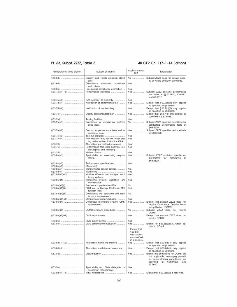
62
40 CFR Ch. I (7–1–14 Edition) Pt. 63, Subpt. ZZZZ, Table 8
General provisions citation Subject of citation Applies to sub-part Explanation
§ 63.6(h) .................................. Opacity and visible emission stand-ards.
No .................. Subpart ZZZZ does not contain opac-ity or visible emission standards.
§ 63.6(i) ................................... Compliance extension procedures and criteria.
Yes.
§ 63.6(j) ................................... Presidential compliance exemption .... Yes. § 63.7(a)(1)–(2) ....................... Performance test dates ...................... Yes ................. Subpart ZZZZ contains performance
test dates at §§ 63.6610, 63.6611, and 63.6612.
§ 63.7(a)(3) ............................. CAA section 114 authority .................. Yes. § 63.7(b)(1) ............................. Notification of performance test ......... Yes ................. Except that § 63.7(b)(1) only applies
as specified in § 63.6645. § 63.7(b)(2) ............................. Notification of rescheduling ................ Yes ................. Except that § 63.7(b)(2) only applies
as specified in § 63.6645. § 63.7(c) .................................. Quality assurance/test plan ................ Yes ................. Except that § 63.7(c) only applies as
specified in § 63.6645. § 63.7(d) .................................. Testing facilities .................................. Yes. § 63.7(e)(1) ............................. Conditions for conducting perform-
ance tests.No. ................. Subpart ZZZZ specifies conditions for
conducting performance tests at § 63.6620.
§ 63.7(e)(2) ............................. Conduct of performance tests and re-duction of data.
Yes ................. Subpart ZZZZ specifies test methods at § 63.6620.
§ 63.7(e)(3) ............................. Test run duration ................................ Yes. § 63.7(e)(4) ............................. Administrator may require other test-
ing under section 114 of the CAA.Yes.
§ 63.7(f) ................................... Alternative test method provisions ..... Yes. § 63.7(g) .................................. Performance test data analysis, rec-
ordkeeping, and reporting.Yes.
§ 63.7(h) .................................. Waiver of tests .................................... Yes. § 63.8(a)(1) ............................. Applicability of monitoring require-
ments.Yes ................. Subpart ZZZZ contains specific re-
quirements for monitoring at § 63.6625.
§ 63.8(a)(2) ............................. Performance specifications ................ Yes. § 63.8(a)(3) ............................. [Reserved] § 63.8(a)(4) ............................. Monitoring for control devices ............ No. § 63.8(b)(1) ............................. Monitoring ........................................... Yes. § 63.8(b)(2)–(3) ....................... Multiple effluents and multiple moni-
toring systems.Yes.
§ 63.8(c)(1) .............................. Monitoring system operation and maintenance.
Yes.
§ 63.8(c)(1)(i) .......................... Routine and predictable SSM ............ No.§ 63.8(c)(1)(ii) .......................... SSM not in Startup Shutdown Mal-
function Plan.Yes.
§ 63.8(c)(1)(iii) ......................... Compliance with operation and main-tenance requirements.
No.
§ 63.8(c)(2)–(3) ....................... Monitoring system installation ............ Yes. § 63.8(c)(4) .............................. Continuous monitoring system (CMS)
requirements.Yes ................. Except that subpart ZZZZ does not
require Continuous Opacity Moni-toring System (COMS).
§ 63.8(c)(5) .............................. COMS minimum procedures .............. No .................. Subpart ZZZZ does not require COMS.
§ 63.8(c)(6)–(8) ....................... CMS requirements .............................. Yes ................. Except that subpart ZZZZ does not require COMS.
§ 63.8(d) .................................. CMS quality control ............................ Yes. § 63.8(e) .................................. CMS performance evaluation ............. Yes ................. Except for § 63.8(e)(5)(ii), which ap-
plies to COMS. Except that § 63.8(e) only applies as specified in § 63.6645.
§ 63.8(f)(1)–(5) ........................ Alternative monitoring method ............ Yes ................. Except that § 63.8(f)(4) only applies as specified in § 63.6645.
§ 63.8(f)(6) .............................. Alternative to relative accuracy test ... Yes ................. Except that § 63.8(f)(6) only applies as specified in § 63.6645.
§ 63.8(g) .................................. Data reduction .................................... Yes ................. Except that provisions for COMS are not applicable. Averaging periods for demonstrating compliance are specified at §§ 63.6635 and 63.6640.
§ 63.9(a) .................................. Applicability and State delegation of notification requirements.
Yes.
§ 63.9(b)(1)–(5) ....................... Initial notifications ............................... Yes ................. Except that § 63.9(b)(3) is reserved.
VerDate Sep<11>2014 13:42 Oct 28, 2014 Jkt 232162 PO 00000 Frm 00072 Fmt 8010 Sfmt 8002 Y:\SGML\232162.XXX 232162wre
ier-
avile
s on
DS
K5T
PT
VN
1PR
OD
with
CF
R

63
Environmental Protection Agency Pt. 63, Subpt. ZZZZ, Table 8
General provisions citation Subject of citation Applies to sub-part Explanation
Except that § 63.9(b) only applies as specified in § 63.6645.
§ 63.9(c) .................................. Request for compliance extension ..... Yes ................. Except that § 63.9(c) only applies as specified in § 63.6645.
§ 63.9(d) .................................. Notification of special compliance re-quirements for new sources.
Yes ................. Except that § 63.9(d) only applies as specified in § 63.6645.
§ 63.9(e) .................................. Notification of performance test ......... Yes ................. Except that § 63.9(e) only applies as specified in § 63.6645.
§ 63.9(f) ................................... Notification of visible emission (VE)/ opacity test.
No .................. Subpart ZZZZ does not contain opac-ity or VE standards.
§ 63.9(g)(1) ............................. Notification of performance evaluation Yes ................. Except that § 63.9(g) only applies as specified in § 63.6645.
§ 63.9(g)(2) ............................. Notification of use of COMS data ...... No .................. Subpart ZZZZ does not contain opac-ity or VE standards.
§ 63.9(g)(3) ............................. Notification that criterion for alter-native to RATA is exceeded.
Yes ................. If alternative is in use.
Except that § 63.9(g) only applies as specified in § 63.6645.
§ 63.9(h)(1)–(6) ....................... Notification of compliance status ........ Yes ................. Except that notifications for sources using a CEMS are due 30 days after completion of performance evaluations. § 63.9(h)(4) is re-served.
Except that § 63.9(h) only applies as specified in § 63.6645.
§ 63.9(i) ................................... Adjustment of submittal deadlines ..... Yes. § 63.9(j) ................................... Change in previous information ......... Yes. § 63.10(a) ................................ Administrative provisions for record-
keeping/reporting.Yes.
§ 63.10(b)(1) ........................... Record retention ................................. Yes ................. Except that the most recent 2 years of data do not have to be retained on site.
§ 63.10(b)(2)(i)–(v) .................. Records related to SSM ..................... No. § 63.10(b)(2)(vi)–(xi) ............... Records .............................................. Yes. § 63.10(b)(2)(xii) ...................... Record when under waiver ................ Yes. § 63.10(b)(2)(xiii) ..................... Records when using alternative to
RATA.Yes ................. For CO standard if using RATA alter-
native. § 63.10(b)(2)(xiv) ..................... Records of supporting documentation Yes. § 63.10(b)(3) ........................... Records of applicability determination Yes. § 63.10(c) ................................ Additional records for sources using
CEMS.Yes ................. Except that § 63.10(c)(2)–(4) and (9)
are reserved. § 63.10(d)(1) ........................... General reporting requirements ......... Yes. § 63.10(d)(2) ........................... Report of performance test results ..... Yes. § 63.10(d)(3) ........................... Reporting opacity or VE observations No .................. Subpart ZZZZ does not contain opac-
ity or VE standards. § 63.10(d)(4) ........................... Progress reports ................................. Yes. § 63.10(d)(5) ........................... Startup, shutdown, and malfunction
reports.No.
§ 63.10(e)(1) and (2)(i) ........... Additional CMS Reports ..................... Yes. § 63.10(e)(2)(ii) ....................... COMS-related report .......................... No .................. Subpart ZZZZ does not require
COMS. § 63.10(e)(3) ........................... Excess emission and parameter
exceedances reports.Yes. ................ Except that § 63.10(e)(3)(i) (C) is re-
served. § 63.10(e)(4) ........................... Reporting COMS data ........................ No .................. Subpart ZZZZ does not require
COMS. § 63.10(f) ................................. Waiver for recordkeeping/reporting .... Yes. § 63.11 .................................... Flares .................................................. No. § 63.12 .................................... State authority and delegations .......... Yes. § 63.13 .................................... Addresses ........................................... Yes. § 63.14 .................................... Incorporation by reference ................. Yes. § 63.15 .................................... Availability of information .................... Yes.
[75 FR 9688, Mar. 3, 2010, as amended at 78 FR 6720, Jan. 30, 2013]
VerDate Sep<11>2014 13:42 Oct 28, 2014 Jkt 232162 PO 00000 Frm 00073 Fmt 8010 Sfmt 8026 Y:\SGML\232162.XXX 232162wre
ier-
avile
s on
DS
K5T
PT
VN
1PR
OD
with
CF
R

64
40 CFR Ch. I (7–1–14 Edition) Pt. 63, Subpt. ZZZZ, App. A
APPENDIX A—PROTOCOL FOR USING AN
ELECTROCHEMICAL ANALYZER TO DE-
TERMINE OXYGEN AND CARBON MON-
OXIDE CONCENTRATIONS FROM CER-
TAIN ENGINES
1.0 SCOPE AND APPLICATION. WHAT IS THIS
PROTOCOL?
This protocol is a procedure for using port-
able electrochemical (EC) cells for meas-
uring carbon monoxide (CO) and oxygen (O2)
concentrations in controlled and uncon-
trolled emissions from existing stationary 4-
stroke lean burn and 4-stroke rich burn re-
ciprocating internal combustion engines as
specified in the applicable rule.
1.1 Analytes. What does this protocol determine?
This protocol measures the engine exhaust
gas concentrations of carbon monoxide (CO)
and oxygen (O2).
Analyte CAS No. Sensitivity
Carbon monoxide (CO) ................................................. 630–08–0 Minimum detectable limit should be 2 percent of the nominal range or 1 ppm, whichever is less restric-tive.
Oxygen (O2) ................................................................... 7782–44–7
1.2 Applicability. When is this protocol
acceptable?
This protocol is applicable to 40 CFR part
63, subpart ZZZZ. Because of inherent cross
sensitivities of EC cells, you must not apply
this protocol to other emissions sources
without specific instruction to that effect.
1.3 Data Quality Objectives. How good must my
collected data be?
Refer to Section 13 to verify and document
acceptable analyzer performance.
1.4 Range. What is the targeted analytical range
for this protocol?
The measurement system and EC cell de-
sign(s) conforming to this protocol will de-
termine the analytical range for each gas
component. The nominal ranges are defined
by choosing up-scale calibration gas con-
centrations near the maximum anticipated
flue gas concentrations for CO and O2, or no
more than twice the permitted CO level.
1.5 Sensitivity. What minimum detectable limit
will this protocol yield for a particular gas
component?
The minimum detectable limit depends on
the nominal range and resolution of the spe-
cific EC cell used, and the signal to noise
ratio of the measurement system. The min-
imum detectable limit should be 2 percent of
the nominal range or 1 ppm, whichever is
less restrictive.
2.0 SUMMARY OF PROTOCOL
In this protocol, a gas sample is extracted
from an engine exhaust system and then con-
veyed to a portable EC analyzer for measure-
ment of CO and O2 gas concentrations. This
method provides measurement system per-
formance specifications and sampling proto-
cols to ensure reliable data. You may use ad-
ditions to, or modifications of vendor sup-
plied measurement systems (e.g., heated or
unheated sample lines, thermocouples, flow
meters, selective gas scrubbers, etc.) to meet
the design specifications of this protocol. Do
not make changes to the measurement sys-
tem from the as-verified configuration (Sec-
tion 3.12).
3.0 DEFINITIONS
3.1 Measurement System. The total equip-
ment required for the measurement of CO
and O2 concentrations. The measurement
system consists of the following major sub-
systems:
3.1.1 Data Recorder. A strip chart recorder,
computer or digital recorder for logging
measurement data from the analyzer output.
You may record measurement data from the
digital data display manually or electroni-
cally.
3.1.2 Electrochemical (EC) Cell. A device,
similar to a fuel cell, used to sense the pres-
ence of a specific analyte and generate an
electrical current output proportional to the
analyte concentration.
3.1.3 Interference Gas Scrubber. A device
used to remove or neutralize chemical com-
pounds that may interfere with the selective
operation of an EC cell.
3.1.4 Moisture Removal System. Any device
used to reduce the concentration of moisture
in the sample stream so as to protect the EC
cells from the damaging effects of condensa-
tion and to minimize errors in measurements
caused by the scrubbing of soluble gases.
3.1.5 Sample Interface. The portion of the
system used for one or more of the following:
sample acquisition; sample transport; sam-
ple conditioning or protection of the EC cell
from any degrading effects of the engine ex-
haust effluent; removal of particulate mat-
ter and condensed moisture.
3.2 Nominal Range. The range of analyte
concentrations over which each EC cell is op-
erated (normally 25 percent to 150 percent of
up-scale calibration gas value). Several
nominal ranges can be used for any given
VerDate Sep<11>2014 13:42 Oct 28, 2014 Jkt 232162 PO 00000 Frm 00074 Fmt 8010 Sfmt 8002 Y:\SGML\232162.XXX 232162wre
ier-
avile
s on
DS
K5T
PT
VN
1PR
OD
with
CF
R

65
Environmental Protection Agency Pt. 63, Subpt. ZZZZ, App. A
cell so long as the calibration and repeat-
ability checks for that range remain within
specifications.
3.3 Calibration Gas. A vendor certified con-
centration of a specific analyte in an appro-
priate balance gas.
3.4 Zero Calibration Error. The analyte con-
centration output exhibited by the EC cell in
response to zero-level calibration gas.
3.5 Up-Scale Calibration Error. The mean of
the difference between the analyte con-
centration exhibited by the EC cell and the
certified concentration of the up-scale cali-
bration gas.
3.6 Interference Check. A procedure for
quantifying analytical interference from
components in the engine exhaust gas other
than the targeted analytes.
3.7 Repeatability Check. A protocol for dem-
onstrating that an EC cell operated over a
given nominal analyte concentration range
provides a stable and consistent response and
is not significantly affected by repeated ex-
posure to that gas.
3.8 Sample Flow Rate. The flow rate of the
gas sample as it passes through the EC cell.
In some situations, EC cells can experience
drift with changes in flow rate. The flow rate
must be monitored and documented during
all phases of a sampling run.
3.9 Sampling Run. A timed three-phase
event whereby an EC cell’s response rises
and plateaus in a sample conditioning phase,
remains relatively constant during a meas-
urement data phase, then declines during a
refresh phase. The sample conditioning phase
exposes the EC cell to the gas sample for a
length of time sufficient to reach a constant
response. The measurement data phase is the
time interval during which gas sample meas-
urements can be made that meet the accept-
ance criteria of this protocol. The refresh
phase then purges the EC cells with CO-free
air. The refresh phase replenishes requisite
O2 and moisture in the electrolyte reserve
and provides a mechanism to de-gas or
desorb any interference gas scrubbers or fil-
ters so as to enable a stable CO EC cell re-
sponse. There are four primary types of sam-
pling runs: pre- sampling calibrations; stack
gas sampling; post-sampling calibration
checks; and measurement system repeat-
ability checks. Stack gas sampling runs can
be chained together for extended evalua-
tions, providing all other procedural speci-
fications are met.
3.10 Sampling Day. A time not to exceed
twelve hours from the time of the pre-sam-
pling calibration to the post-sampling cali-
bration check. During this time, stack gas
sampling runs can be repeated without re-
peated recalibrations, providing all other
sampling specifications have been met.
3.11 Pre-Sampling Calibration/Post-Sampling
Calibration Check. The protocols executed at
the beginning and end of each sampling day
to bracket measurement readings with con-
trolled performance checks. 3.12 Performance-Established Configuration.
The EC cell and sampling system configura-
tion that existed at the time that it initially
met the performance requirements of this
protocol.
4.0 INTERFERENCES.
When present in sufficient concentrations,
NO and NO2 are two gas species that have
been reported to interfere with CO con-
centration measurements. In the likelihood
of this occurrence, it is the protocol user’s
responsibility to employ and properly main-
tain an appropriate CO EC cell filter or
scrubber for removal of these gases, as de-
scribed in Section 6.2.12.
5.0 SAFETY. [RESERVED]
6.0 EQUIPMENT AND SUPPLIES.
6.1 What equipment do I need for the measurement system?
The system must maintain the gas sample
at conditions that will prevent moisture con-
densation in the sample transport lines, both
before and as the sample gas contacts the EC
cells. The essential components of the meas-
urement system are described below.
6.2 Measurement System Components.
6.2.1 Sample Probe. A single extraction-
point probe constructed of glass, stainless
steel or other non-reactive material, and of
length sufficient to reach any designated
sampling point. The sample probe must be
designed to prevent plugging due to con-
densation or particulate matter. 6.2.2 Sample Line. Non-reactive tubing to
transport the effluent from the sample probe
to the EC cell. 6.2.3 Calibration Assembly (optional). A
three-way valve assembly or equivalent to
introduce calibration gases at ambient pres-
sure at the exit end of the sample probe dur-
ing calibration checks. The assembly must
be designed such that only stack gas or cali-
bration gas flows in the sample line and all
gases flow through any gas path filters. 6.2.4 Particulate Filter (optional). Filters be-
fore the inlet of the EC cell to prevent accu-
mulation of particulate material in the
measurement system and extend the useful
life of the components. All filters must be
fabricated of materials that are non-reactive
to the gas mixtures being sampled. 6.2.5 Sample Pump. A leak-free pump to pro-
vide undiluted sample gas to the system at a
flow rate sufficient to minimize the response
time of the measurement system. If located
upstream of the EC cells, the pump must be
constructed of a material that is non-reac-
tive to the gas mixtures being sampled. 6.2.8 Sample Flow Rate Monitoring. An ad-
justable rotameter or equivalent device used
VerDate Sep<11>2014 13:42 Oct 28, 2014 Jkt 232162 PO 00000 Frm 00075 Fmt 8010 Sfmt 8002 Y:\SGML\232162.XXX 232162wre
ier-
avile
s on
DS
K5T
PT
VN
1PR
OD
with
CF
R

66
40 CFR Ch. I (7–1–14 Edition) Pt. 63, Subpt. ZZZZ, App. A
to adjust and maintain the sample flow rate
through the analyzer as prescribed.
6.2.9 Sample Gas Manifold (optional). A
manifold to divert a portion of the sample
gas stream to the analyzer and the remain-
der to a by-pass discharge vent. The sample
gas manifold may also include provisions for
introducing calibration gases directly to the
analyzer. The manifold must be constructed
of a material that is non-reactive to the gas
mixtures being sampled.
6.2.10 EC cell. A device containing one or
more EC cells to determine the CO and O2 concentrations in the sample gas stream.
The EC cell(s) must meet the applicable per-
formance specifications of Section 13 of this
protocol.
6.2.11 Data Recorder. A strip chart recorder,
computer or digital recorder to make a
record of analyzer output data. The data re-
corder resolution (i.e., readability) must be
no greater than 1 ppm for CO; 0.1 percent for
O2; and one degree (either °C or °F) for tem-
perature. Alternatively, you may use a dig-
ital or analog meter having the same resolu-
tion to observe and manually record the ana-
lyzer responses.
6.2.12 Interference Gas Filter or Scrubber. A
device to remove interfering compounds up-
stream of the CO EC cell. Specific inter-
ference gas filters or scrubbers used in the
performance-established configuration of the
analyzer must continue to be used. Such a
filter or scrubber must have a means to de-
termine when the removal agent is ex-
hausted. Periodically replace or replenish it
in accordance with the manufacturer’s rec-
ommendations.
7.0 REAGENTS AND STANDARDS. WHAT
CALIBRATION GASES ARE NEEDED?
7.1 Calibration Gases. CO calibration gases
for the EC cell must be CO in nitrogen or CO
in a mixture of nitrogen and O2. Use CO cali-
bration gases with labeled concentration val-
ues certified by the manufacturer to be with-
in ±5 percent of the label value. Dry ambient
air (20.9 percent O2) is acceptable for calibra-
tion of the O2 cell. If needed, any lower per-
centage O2 calibration gas must be a mixture
of O2 in nitrogen.
7.1.1 Up-Scale CO Calibration Gas Concentra-
tion. Choose one or more up-scale gas con-
centrations such that the average of the
stack gas measurements for each stack gas
sampling run are between 25 and 150 percent
of those concentrations. Alternatively,
choose an up-scale gas that does not exceed
twice the concentration of the applicable
outlet standard. If a measured gas value ex-
ceeds 150 percent of the up-scale CO calibra-
tion gas value at any time during the stack
gas sampling run, the run must be discarded
and repeated.
7.1.2 Up-Scale O2 Calibration Gas Concentra-
tion.
Select an O2 gas concentration such that
the difference between the gas concentration
and the average stack gas measurement or
reading for each sample run is less than 15
percent O2. When the average exhaust gas O2 readings are above 6 percent, you may use
dry ambient air (20.9 percent O2) for the up-
scale O2 calibration gas. 7.1.3 Zero Gas. Use an inert gas that con-
tains less than 0.25 percent of the up-scale
CO calibration gas concentration. You may
use dry air that is free from ambient CO and
other combustion gas products (e.g., CO2).
8.0 SAMPLE COLLECTION AND ANALYSIS
8.1 Selection of Sampling Sites. 8.1.1 Control Device Inlet. Select a sampling
site sufficiently downstream of the engine so
that the combustion gases should be well
mixed. Use a single sampling extraction
point near the center of the duct (e.g., within
the 10 percent centroidal area), unless in-
structed otherwise. 8.1.2 Exhaust Gas Outlet. Select a sampling
site located at least two stack diameters
downstream of any disturbance (e.g., turbo-
charger exhaust, crossover junction or recir-
culation take-off) and at least one-half stack
diameter upstream of the gas discharge to
the atmosphere. Use a single sampling ex-
traction point near the center of the duct
(e.g., within the 10 percent centroidal area),
unless instructed otherwise. 8.2 Stack Gas Collection and Analysis. Prior
to the first stack gas sampling run, conduct
that the pre-sampling calibration in accord-
ance with Section 10.1. Use Figure 1 to
record all data. Zero the analyzer with zero
gas. Confirm and record that the scrubber
media color is correct and not exhausted.
Then position the probe at the sampling
point and begin the sampling run at the
same flow rate used during the up-scale cali-
bration. Record the start time. Record all EC
cell output responses and the flow rate dur-
ing the ‘‘sample conditioning phase’’ once
per minute until constant readings are ob-
tained. Then begin the ‘‘measurement data
phase’’ and record readings every 15 seconds
for at least two minutes (or eight readings),
or as otherwise required to achieve two con-
tinuous minutes of data that meet the speci-
fication given in Section 13.1. Finally, per-
form the ‘‘refresh phase’’ by introducing dry
air, free from CO and other combustion
gases, until several minute-to-minute read-
ings of consistent value have been obtained.
For each run use the ‘‘measurement data
phase’’ readings to calculate the average
stack gas CO and O2 concentrations. 8.3 EC Cell Rate. Maintain the EC cell sam-
ple flow rate so that it does not vary by more
than ±10 percent throughout the pre-sam-
pling calibration, stack gas sampling and
post-sampling calibration check. Alter-
natively, the EC cell sample flow rate can be
maintained within a tolerance range that
VerDate Sep<11>2014 13:42 Oct 28, 2014 Jkt 232162 PO 00000 Frm 00076 Fmt 8010 Sfmt 8002 Y:\SGML\232162.XXX 232162wre
ier-
avile
s on
DS
K5T
PT
VN
1PR
OD
with
CF
R

67
Environmental Protection Agency Pt. 63, Subpt. ZZZZ, App. A
does not affect the gas concentration read-
ings by more than ±3 percent, as instructed
by the EC cell manufacturer.
9.0 QUALITY CONTROL (RESERVED)
10.0 CALIBRATION AND STANDARDIZATION
10.1 Pre-Sampling Calibration. Conduct the
following protocol once for each nominal
range to be used on each EC cell before per-
forming a stack gas sampling run on each
field sampling day. Repeat the calibration if
you replace an EC cell before completing all
of the sampling runs. There is no prescribed
order for calibration of the EC cells; how-
ever, each cell must complete the measure-
ment data phase during calibration. Assem-
ble the measurement system by following
the manufacturer’s recommended protocols
including for preparing and preconditioning
the EC cell. Assure the measurement system
has no leaks and verify the gas scrubbing
agent is not depleted. Use Figure 1 to record
all data. 10.1.1 Zero Calibration. For both the O2 and
CO cells, introduce zero gas to the measure-
ment system (e.g., at the calibration assem-
bly) and record the concentration reading
every minute until readings are constant for
at least two consecutive minutes. Include
the time and sample flow rate. Repeat the
steps in this section at least once to verify
the zero calibration for each component gas. 10.1.2 Zero Calibration Tolerance. For each
zero gas introduction, the zero level output
must be less than or equal to ±3 percent of
the up-scale gas value or ±1 ppm, whichever
is less restrictive, for the CO channel and
less than or equal to ±0.3 percent O2 for the
O2 channel. 10.1.3 Up-Scale Calibration. Individually in-
troduce each calibration gas to the measure-
ment system (e.g., at the calibration assem-
bly) and record the start time. Record all EC
cell output responses and the flow rate dur-
ing this ‘‘sample conditioning phase’’ once
per minute until readings are constant for at
least two minutes. Then begin the ‘‘meas-
urement data phase’’ and record readings
every 15 seconds for a total of two minutes,
or as otherwise required. Finally, perform
the ‘‘refresh phase’’ by introducing dry air,
free from CO and other combustion gases,
until readings are constant for at least two
consecutive minutes. Then repeat the steps
in this section at least once to verify the
calibration for each component gas. Intro-
duce all gases to flow through the entire
sample handling system (i.e., at the exit end
of the sampling probe or the calibration as-
sembly). 10.1.4 Up-Scale Calibration Error. The mean
of the difference of the ‘‘measurement data
phase’’ readings from the reported standard
gas value must be less than or equal to ±5
percent or ±1 ppm for CO or ±0.5 percent O2,
whichever is less restrictive, respectively.
The maximum allowable deviation from the
mean measured value of any single ‘‘meas-
urement data phase’’ reading must be less
than or equal to ±2 percent or ±1 ppm for CO
or ±0.5 percent O2, whichever is less restric-
tive, respectively.
10.2 Post-Sampling Calibration Check. Con-
duct a stack gas post-sampling calibration
check after the stack gas sampling run or set
of runs and within 12 hours of the initial
calibration. Conduct up-scale and zero cali-
bration checks using the protocol in Section
10.1. Make no changes to the sampling sys-
tem or EC cell calibration until all post-sam-
pling calibration checks have been recorded.
If either the zero or up-scale calibration
error exceeds the respective specification in
Sections 10.1.2 and 10.1.4 then all measure-
ment data collected since the previous suc-
cessful calibrations are invalid and re-cali-
bration and re-sampling are required. If the
sampling system is disassembled or the EC
cell calibration is adjusted, repeat the cali-
bration check before conducting the next an-
alyzer sampling run.
11.0 ANALYTICAL PROCEDURE
The analytical procedure is fully discussed
in Section 8.
12.0 CALCULATIONS AND DATA ANALYSIS
Determine the CO and O2 concentrations
for each stack gas sampling run by calcu-
lating the mean gas concentrations of the
data recorded during the ‘‘measurement data
phase’’.
13.0 PROTOCOL PERFORMANCE
Use the following protocols to verify con-
sistent analyzer performance during each
field sampling day.
13.1 Measurement Data Phase Performance
Check. Calculate the mean of the readings
from the ‘‘measurement data phase’’. The
maximum allowable deviation from the
mean for each of the individual readings is ±2
percent, or ±1 ppm, whichever is less restric-
tive. Record the mean value and maximum
deviation for each gas monitored. Data must
conform to Section 10.1.4. The EC cell flow
rate must conform to the specification in
Section 8.3.
Example: A measurement data phase is in-
valid if the maximum deviation of any single
reading comprising that mean is greater
than ±2 percent or ±1 ppm (the default cri-
teria). For example, if the mean = 30 ppm,
single readings of below 29 ppm and above 31
ppm are disallowed).
13.2 Interference Check. Before the initial
use of the EC cell and interference gas scrub-
ber in the field, and semi-annually there-
after, challenge the interference gas scrub-
ber with NO and NO2 gas standards that are
VerDate Sep<11>2014 13:42 Oct 28, 2014 Jkt 232162 PO 00000 Frm 00077 Fmt 8010 Sfmt 8002 Y:\SGML\232162.XXX 232162wre
ier-
avile
s on
DS
K5T
PT
VN
1PR
OD
with
CF
R

68
40 CFR Ch. I (7–1–14 Edition) Pt. 63, Subpt. ZZZZ, App. A
generally recognized as representative of die-
sel-fueled engine NO and NO2 emission val-
ues. Record the responses displayed by the
CO EC cell and other pertinent data on Fig-
ure 1 or a similar form. 13.2.1 Interference Response. The combined
NO and NO2 interference response should be
less than or equal to ±5 percent of the up-
scale CO calibration gas concentration. 13.3 Repeatability Check. Conduct the fol-
lowing check once for each nominal range
that is to be used on the CO EC cell within
5 days prior to each field sampling program.
If a field sampling program lasts longer than
5 days, repeat this check every 5 days. Imme-
diately repeat the check if the EC cell is re-
placed or if the EC cell is exposed to gas con-
centrations greater than 150 percent of the
highest up-scale gas concentration. 13.3.1 Repeatability Check Procedure. Per-
form a complete EC cell sampling run (all
three phases) by introducing the CO calibra-
tion gas to the measurement system and
record the response. Follow Section 10.1.3.
Use Figure 1 to record all data. Repeat the
run three times for a total of four complete
runs. During the four repeatability check
runs, do not adjust the system except where
necessary to achieve the correct calibration
gas flow rate at the analyzer. 13.3.2 Repeatability Check Calculations. De-
termine the highest and lowest average
‘‘measurement data phase’’ CO concentra-
tions from the four repeatability check runs
and record the results on Figure 1 or a simi-
lar form. The absolute value of the difference
between the maximum and minimum aver-
age values recorded must not vary more than
±3 percent or ±1 ppm of the up-scale gas
value, whichever is less restrictive.
14.0 POLLUTION PREVENTION (RESERVED)
15.0 WASTE MANAGEMENT (RESERVED)
16.0 ALTERNATIVE PROCEDURES (RESERVED)
17.0 REFERENCES
(1) ‘‘Development of an Electrochemical
Cell Emission Analyzer Test Protocol’’, Top-
ical Report, Phil Juneau, Emission Moni-
toring, Inc., July 1997.
(2) ‘‘Determination of Nitrogen Oxides,
Carbon Monoxide, and Oxygen Emissions
from Natural Gas-Fired Engines, Boilers, and
Process Heaters Using Portable Analyzers’’,
EMC Conditional Test Protocol 30 (CTM–30),
Gas Research Institute Protocol GRI–96/0008,
Revision 7, October 13, 1997.
(3) ‘‘ICAC Test Protocol for Periodic Moni-
toring’’, EMC Conditional Test Protocol 34
(CTM–034), The Institute of Clean Air Com-
panies, September 8, 1999.
(4) ‘‘Code of Federal Regulations’’, Protec-
tion of Environment, 40 CFR, Part 60, Appen-
dix A, Methods 1–4; 10.
VerDate Sep<11>2014 13:42 Oct 28, 2014 Jkt 232162 PO 00000 Frm 00078 Fmt 8010 Sfmt 8002 Y:\SGML\232162.XXX 232162wre
ier-
avile
s on
DS
K5T
PT
VN
1PR
OD
with
CF
R

69
Environmental Protection Agency Pt. 63, Subpt. ZZZZ, App. A
TA
BLE
1: A
PP
EN
DIX
A—
SA
MP
LIN
GR
UN
DA
TA.
Fac
ility
ll
ll
ll
ll
ll
Eng
ine
I.D.l
ll
ll
ll
ll
lD
atel
ll
ll
l
Run
Typ
e:...
......
......
......
......
......
......
......
......
......
......
.....
(ll
(l
l
(ll
(l
) (X
)...
......
......
......
......
......
......
......
......
......
......
......
......
.....
Pre
-Sam
ple
Cal
ibra
tion
Sta
ck G
as S
ampl
e P
ost-
Sam
ple
Cal
. C
heck
R
epea
tabi
lity
Che
ck
Run
#...
......
......
......
......
......
.....
1 1
2 2
3 3
4 4
Tim
e S
crub
. O
K
Flo
w-
Rat
e G
as...
......
......
......
......
......
......
...O
2
CO
O
2
CO
O
2
CO
O
2
CO
...
......
......
......
......
......
......
......
......
......
......
......
......
......
......
......
....
......
......
......
......
......
......
......
......
......
......
......
......
......
......
......
......
......
......
......
......
......
......
......
......
Sam
ple
Con
d....
......
......
......
....
Pha
se...
......
......
......
......
......
.....
......
......
......
......
......
......
......
......
......
......
......
......
......
......
......
......
......
......
......
......
......
......
......
......
″...
......
......
......
......
......
......
......
.....
......
......
......
......
......
......
......
......
......
......
......
......
......
......
......
......
......
......
......
......
......
......
......
...″
......
......
......
......
......
......
......
.....
......
......
......
......
......
......
......
......
......
......
......
......
......
......
......
......
......
......
......
......
......
......
......
......
......
......
......
......
......
......
......
......
....
......
......
......
......
......
......
......
......
......
......
......
......
......
......
......
......
......
......
......
......
......
......
......
...M
easu
rem
ent
......
......
......
......
..D
ata
Pha
se...
......
......
......
......
.....
......
......
......
......
......
......
......
......
......
......
......
......
......
......
......
......
......
......
......
......
......
......
......
...″
......
......
......
......
......
......
......
.....
......
......
......
......
......
......
......
......
......
......
......
......
......
......
......
......
......
......
......
......
......
......
......
......
″...
......
......
......
......
......
......
......
.....
......
......
......
......
......
......
......
......
......
......
......
......
......
......
......
......
......
......
......
......
......
......
......
...″
......
......
......
......
......
......
......
.....
......
......
......
......
......
......
......
......
......
......
......
......
......
......
......
......
......
......
......
......
......
......
......
......
″...
......
......
......
......
......
......
......
.....
......
......
......
......
......
......
......
......
......
......
......
......
......
......
......
......
......
......
......
......
......
......
......
......
......
......
......
......
......
......
......
....
......
......
......
......
......
......
......
......
......
......
......
......
......
......
......
......
......
......
......
......
......
......
......
......
Mea
n...
......
......
......
......
......
......
......
......
......
......
......
......
......
......
......
......
......
......
......
......
......
......
......
......
......
......
......
......
......
......
......
......
......
......
......
......
......
......
....
......
......
......
......
......
......
......
......
......
......
......
......
......
......
......
......
......
......
......
......
......
......
......
...R
efre
sh...
......
......
......
......
......
...P
hase
......
......
......
......
......
......
.....
......
......
......
......
......
......
......
......
......
......
......
......
......
......
......
......
......
......
......
......
......
......
......
...″
......
......
......
......
......
......
......
.....
......
......
......
......
......
......
......
......
......
......
......
......
......
......
......
......
......
......
......
......
......
......
......
......
″...
......
......
......
......
......
......
......
.....
......
......
......
......
......
......
......
......
......
......
......
......
......
......
......
......
......
......
......
......
......
......
......
......
......
......
......
...
[78 F
R 6
721, J
an
. 30, 2013]
VerDate Sep<11>2014 13:42 Oct 28, 2014 Jkt 232162 PO 00000 Frm 00079 Fmt 8010 Sfmt 8027 Y:\SGML\232162.XXX 232162wre
ier-
avile
s on
DS
K5T
PT
VN
1PR
OD
with
CF
R

Appendix D

131
Environmental Protection Agency § 63.7491
Citation Subject Applies to Subpart CCCCC? Explanation
§ 63.10(c)(7)–(8) ............ Records of Excess Emissions and Parameter Monitoring Exceedances for CMS.
No ................................. Subpart CCCCC specifies record requirements.
§ 63.10(e)(3) .................. Excess Emission Reports ................ No ................................. Subpart CCCCC specifies reporting requirements.
§ 63.11 ........................... Control Device Requirements .......... No ................................. Subpart CCCCC does not require flares.
§ 63.12 ........................... State Authority and Delegations. ..... Yes.§§ 63.13–63.15 .............. Addresses, Incorporation by Ref-
erence, Availability of Information.Yes.
Subpart DDDDD—National Emis-sion Standards for Hazardous Air Pollutants for Major Sources: Industrial, Commer-cial, and Institutional Boilers and Process Heaters
SOURCE: 76 FR 15664, Mar. 21, 2011, unless
otherwise noted.
WHAT THIS SUBPART COVERS
§ 63.7480 What is the purpose of this subpart?
This subpart establishes national
emission limitations and work practice
standards for hazardous air pollutants
(HAP) emitted from industrial, com-
mercial, and institutional boilers and
process heaters located at major
sources of HAP. This subpart also es-
tablishes requirements to demonstrate
initial and continuous compliance with
the emission limitations and work
practice standards.
§ 63.7485 Am I subject to this subpart?
You are subject to this subpart if you
own or operate an industrial, commer-
cial, or institutional boiler or process
heater as defined in § 63.7575 that is lo-
cated at, or is part of, a major source
of HAP, except as specified in § 63.7491.
For purposes of this subpart, a major
source of HAP is as defined in § 63.2, ex-
cept that for oil and natural gas pro-
duction facilities, a major source of
HAP is as defined in § 63.7575.
[78 FR 7162, Jan. 31, 2013]
§ 63.7490 What is the affected source of this subpart?
(a) This subpart applies to new, re-
constructed, and existing affected
sources as described in paragraphs
(a)(1) and (2) of this section.
(1) The affected source of this subpart
is the collection at a major source of
all existing industrial, commercial,
and institutional boilers and process
heaters within a subcategory as defined
in § 63.7575.
(2) The affected source of this subpart
is each new or reconstructed indus-
trial, commercial, or institutional boil-
er or process heater, as defined in
§ 63.7575, located at a major source.
(b) A boiler or process heater is new
if you commence construction of the
boiler or process heater after June 4,
2010, and you meet the applicability
criteria at the time you commence
construction.
(c) A boiler or process heater is re-
constructed if you meet the recon-
struction criteria as defined in § 63.2,
you commence reconstruction after
June 4, 2010, and you meet the applica-
bility criteria at the time you com-
mence reconstruction.
(d) A boiler or process heater is exist-
ing if it is not new or reconstructed.
(e) An existing electric utility steam
generating unit (EGU) that meets the
applicability requirements of this sub-
part after the effective date of this
final rule due to a change (e.g., fuel
switch) is considered to be an existing
source under this subpart.
[76 FR 15664, Mar. 21, 2011, as amended at 78
FR 7162, Jan. 31, 2013]
§ 63.7491 Are any boilers or process heaters not subject to this subpart?
The types of boilers and process heat-
ers listed in paragraphs (a) through (n)
of this section are not subject to this
subpart.
VerDate Sep<11>2014 13:42 Oct 28, 2014 Jkt 232162 PO 00000 Frm 00141 Fmt 8010 Sfmt 8010 Y:\SGML\232162.XXX 232162wre
ier-
avile
s on
DS
K5T
PT
VN
1PR
OD
with
CF
R

132
40 CFR Ch. I (7–1–14 Edition) § 63.7495
(a) An electric utility steam gener-
ating unit (EGU) covered by subpart
UUUUU of this part.
(b) A recovery boiler or furnace cov-
ered by subpart MM of this part.
(c) A boiler or process heater that is
used specifically for research and de-
velopment, including test steam boil-
ers used to provide steam for testing
the propulsion systems on military
vessels. This does not include units
that provide heat or steam to a process
at a research and development facility.
(d) A hot water heater as defined in
this subpart.
(e) A refining kettle covered by sub-
part X of this part.
(f) An ethylene cracking furnace cov-
ered by subpart YY of this part.
(g) Blast furnace stoves as described
in EPA–453/R–01–005 (incorporated by
reference, see § 63.14).
(h) Any boiler or process heater that
is part of the affected source subject to
another subpart of this part, such as
boilers and process heaters used as con-
trol devices to comply with subparts
JJJ, OOO, PPP, and U of this part.
(i) Any boiler or process heater that
is used as a control device to comply
with another subpart of this part, or
part 60, part 61, or part 65 of this chap-
ter provided that at least 50 percent of
the average annual heat input during
any 3 consecutive calendar years to the
boiler or process heater is provided by
regulated gas streams that are subject
to another standard.
(j) Temporary boilers as defined in
this subpart.
(k) Blast furnace gas fuel-fired boil-
ers and process heaters as defined in
this subpart.
(l) Any boiler specifically listed as an
affected source in any standard(s) es-
tablished under section 129 of the Clean
Air Act.
(m) A unit that burns hazardous
waste covered by Subpart EEE of this
part. A unit that is exempt from Sub-
part EEE as specified in § 63.1200(b) is
not covered by Subpart EEE.
[76 FR 15664, Mar. 21, 2011, as amended at 78
FR 7162, Jan. 31, 2013]
EDITORIAL NOTE: At 78 FR 7162, Jan. 31,
2013, § 63.7491 was amended by revising para-
graph (n). However, there is no paragraph (n)
to be revised.
§ 63.7495 When do I have to comply with this subpart?
(a) If you have a new or recon-structed boiler or process heater, you must comply with this subpart by Jan-uary 31, 2013, or upon startup of your boiler or process heater, whichever is later.
(b) If you have an existing boiler or process heater, you must comply with this subpart no later than January 31, 2016, except as provided in § 63.6(i).
(c) If you have an area source that in-creases its emissions or its potential to emit such that it becomes a major source of HAP, paragraphs (c)(1) and (2)
of this section apply to you. (1) Any new or reconstructed boiler
or process heater at the existing source
must be in compliance with this sub-
part upon startup. (2) Any existing boiler or process
heater at the existing source must be
in compliance with this subpart within
3 years after the source becomes a
major source. (d) You must meet the notification
requirements in § 63.7545 according to
the schedule in § 63.7545 and in subpart
A of this part. Some of the notifica-
tions must be submitted before you are
required to comply with the emission
limits and work practice standards in
this subpart. (e) If you own or operate an indus-
trial, commercial, or institutional boil-
er or process heater and would be sub-
ject to this subpart except for the ex-
emption in § 63.7491(l) for commercial
and industrial solid waste incineration
units covered by part 60, subpart CCCC
or subpart DDDD, and you cease com-
busting solid waste, you must be in
compliance with this subpart on the ef-
fective date of the switch from waste
to fuel. (f) If you own or operate an existing
EGU that becomes subject to this sub-
part after January 31, 2013, you must be
in compliance with the applicable ex-
isting source provisions of this subpart
on the effective date such unit becomes
subject to this subpart. (g) If you own or operate an existing
industrial, commercial, or institu-
tional boiler or process heater and
would be subject to this subpart except
for a exemption in § 63.7491(i) that be-
comes subject to this subpart after
VerDate Sep<11>2014 13:42 Oct 28, 2014 Jkt 232162 PO 00000 Frm 00142 Fmt 8010 Sfmt 8010 Y:\SGML\232162.XXX 232162wre
ier-
avile
s on
DS
K5T
PT
VN
1PR
OD
with
CF
R

133
Environmental Protection Agency § 63.7500
January 31, 2013, you must be in com-
pliance with the applicable existing
source provisions of this subpart with-
in 3 years after such unit becomes sub-
ject to this subpart.
[76 FR 15664, Mar. 21, 2011, as amended at 78
FR 7162, Jan. 31, 2013]
EDITORIAL NOTE: At 78 FR 7162, Jan. 31,
2013, § 63.7495 was amended by adding para-
graph (e). However, there is already a para-
graph (e).
EMISSION LIMITATIONS AND WORK
PRACTICE STANDARDS
§ 63.7499 What are the subcategories of boilers and process heaters?
The subcategories of boilers and
process heaters, as defined in § 63.7575
are:
(a) Pulverized coal/solid fossil fuel
units.
(b) Stokers designed to burn coal/
solid fossil fuel.
(c) Fluidized bed units designed to
burn coal/solid fossil fuel.
(d) Stokers/sloped grate/other units
designed to burn kiln dried biomass/
bio-based solid.
(e) Fluidized bed units designed to
burn biomass/bio-based solid.
(f) Suspension burners designed to
burn biomass/bio-based solid.
(g) Fuel cells designed to burn bio-
mass/bio-based solid.
(h) Hybrid suspension/grate burners
designed to burn wet biomass/bio-based
solid.
(i) Stokers/sloped grate/other units
designed to burn wet biomass/bio-based
solid.
(j) Dutch ovens/pile burners designed
to burn biomass/bio-based solid.
(k) Units designed to burn liquid fuel
that are non-continental units.
(l) Units designed to burn gas 1 fuels.
(m) Units designed to burn gas 2
(other) gases.
(n) Metal process furnaces.
(o) Limited-use boilers and process
heaters.
(p) Units designed to burn solid fuel.
(q) Units designed to burn liquid fuel.
(r) Units designed to burn coal/solid
fossil fuel.
(s) Fluidized bed units with an inte-
grated fluidized bed heat exchanger de-
signed to burn coal/solid fossil fuel.
(t) Units designed to burn heavy liq-
uid fuel.
(u) Units designed to burn light liq-
uid fuel.
[76 FR 15664, Mar. 21, 2011, as amended at 78
FR 7163, Jan. 31, 2013]
§ 63.7500 What emission limitations, work practice standards, and oper-ating limits must I meet?
(a) You must meet the requirements
in paragraphs (a)(1) through (3) of this
section, except as provided in para-
graphs (b), through (e) of this section.
You must meet these requirements at
all times the affected unit is operating,
except as provided in paragraph (f) of
this section.
(1) You must meet each emission
limit and work practice standard in
Tables 1 through 3, and 11 through 13 to
this subpart that applies to your boiler
or process heater, for each boiler or
process heater at your source, except
as provided under § 63.7522. The output-
based emission limits, in units of
pounds per million Btu of steam out-
put, in Tables 1 or 2 to this subpart are
an alternative applicable only to boil-
ers and process heaters that generate
steam. The output-based emission lim-
its, in units of pounds per megawatt-
hour, in Tables 1 or 2 to this subpart
are an alternative applicable only to
boilers that generate electricity. If you
operate a new boiler or process heater,
you can choose to comply with alter-
native limits as discussed in para-
graphs (a)(1)(i) through (a)(1)(iii) of
this section, but on or after January 31,
2016, you must comply with the emis-
sion limits in Table 1 to this subpart.
(i) If your boiler or process heater
commenced construction or recon-
struction after June 4, 2010 and before
May 20, 2011, you may comply with the
emission limits in Table 1 or 11 to this
subpart until January 31, 2016.
(ii) If your boiler or process heater
commenced construction or recon-
struction after May 20, 2011 and before
December 23, 2011, you may comply
with the emission limits in Table 1 or
12 to this subpart until January 31,
2016.
(iii) If your boiler or process heater
commenced construction or recon-
struction after December 23, 2011 and
VerDate Sep<11>2014 13:42 Oct 28, 2014 Jkt 232162 PO 00000 Frm 00143 Fmt 8010 Sfmt 8010 Y:\SGML\232162.XXX 232162wre
ier-
avile
s on
DS
K5T
PT
VN
1PR
OD
with
CF
R
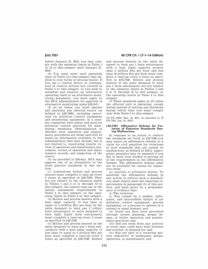
134
40 CFR Ch. I (7–1–14 Edition) § 63.7501
before January 31, 2013, you may com-
ply with the emission limits in Table 1
or 13 to this subpart until January 31,
2016.
(2) You must meet each operating
limit in Table 4 to this subpart that ap-
plies to your boiler or process heater. If
you use a control device or combina-
tion of control devices not covered in
Table 4 to this subpart, or you wish to
establish and monitor an alternative
operating limit or an alternative moni-
toring parameter, you must apply to
the EPA Administrator for approval of
alternative monitoring under § 63.8(f).
(3) At all times, you must operate
and maintain any affected source (as
defined in § 63.7490), including associ-
ated air pollution control equipment
and monitoring equipment, in a man-
ner consistent with safety and good air
pollution control practices for mini-
mizing emissions. Determination of
whether such operation and mainte-
nance procedures are being used will be
based on information available to the
Administrator that may include, but is
not limited to, monitoring results, re-
view of operation and maintenance pro-
cedures, review of operation and main-
tenance records, and inspection of the
source.
(b) As provided in § 63.6(g), EPA may
approve use of an alternative to the
work practice standards in this sec-
tion.
(c) Limited-use boilers and process
heaters must complete a tune-up every
5 years as specified in § 63.7540. They
are not subject to the emission limits
in Tables 1 and 2 or 11 through 13 to
this subpart, the annual tune-up, or the
energy assessment requirements in
Table 3 to this subpart, or the oper-
ating limits in Table 4 to this subpart.
(d) Boilers and process heaters with a
heat input capacity of less than or
equal to 5 million Btu per hour in the
units designed to burn gas 2 (other)
fuels subcategory or units designed to
burn light liquid fuels subcategory
must complete a tune-up every 5 years
as specified in § 63.7540.
(e) Boilers and process heaters in the
units designed to burn gas 1 fuels sub-
category with a heat input capacity of
less than or equal to 5 million Btu per
hour must complete a tune-up every 5
years as specified in § 63.7540. Boilers
and process heaters in the units de-
signed to burn gas 1 fuels subcategory
with a heat input capacity greater
than 5 million Btu per hour and less
than 10 million Btu per hour must com-
plete a tune-up every 2 years as speci-
fied in § 63.7540. Boilers and process
heaters in the units designed to burn
gas 1 fuels subcategory are not subject
to the emission limits in Tables 1 and
2 or 11 through 13 to this subpart, or
the operating limits in Table 4 to this
subpart. (f) These standards apply at all times
the affected unit is operating, except
during periods of startup and shutdown
during which time you must comply
only with Table 3 to this subpart.
[76 FR 15664, Mar. 21, 2011, as amended at 78
FR 7163, Jan. 31, 2013]
§ 63.7501 Affirmative Defense for Vio-lation of Emission Standards Dur-ing Malfunction.
In response to an action to enforce
the standards set forth in § 63.7500 you
may assert an affirmative defense to a
claim for civil penalties for violations
of such standards that are caused by
malfunction, as defined at § 63.2. Appro-
priate penalties may be assessed if you
fail to meet your burden of proving all
of the requirements in the affirmative
defense. The affirmative defense shall
not be available for claims for injunc-
tive relief. (a) Assertion of affirmative defense. To
establish the affirmative defense in
any action to enforce such a standard,
you must timely meet the reporting re-
quirements in paragraph (b) of this sec-
tion, and must prove by a preponder-
ance of evidence that: (1) The violation: (i) Was caused by a sudden, infre-
quent, and unavoidable failure of air
pollution control equipment, process
equipment, or a process to operate in a
normal or usual manner; and (ii) Could not have been prevented
through careful planning, proper de-
sign, or better operation and mainte-
nance practices; and (iii) Did not stem from any activity
or event that could have been foreseen
and avoided, or planned for; and (iv) Was not part of a recurring pat-
tern indicative of inadequate design,
operation, or maintenance; and
VerDate Sep<11>2014 13:42 Oct 28, 2014 Jkt 232162 PO 00000 Frm 00144 Fmt 8010 Sfmt 8010 Y:\SGML\232162.XXX 232162wre
ier-
avile
s on
DS
K5T
PT
VN
1PR
OD
with
CF
R

135
Environmental Protection Agency § 63.7505
(2) Repairs were made as expedi-
tiously as possible when a violation oc-
curred; and
(3) The frequency, amount, and dura-
tion of the violation (including any by-
pass) were minimized to the maximum
extent practicable; and
(4) If the violation resulted from a
bypass of control equipment or a proc-
ess, then the bypass was unavoidable to
prevent loss of life, personal injury, or
severe property damage; and
(5) All possible steps were taken to
minimize the impact of the violation
on ambient air quality, the environ-
ment, and human health; and
(6) All emissions monitoring and con-
trol systems were kept in operation if
at all possible, consistent with safety
and good air pollution control prac-
tices; and
(7) All of the actions in response to
the violation were documented by
properly signed, contemporaneous op-
erating logs; and
(8) At all times, the affected source
was operated in a manner consistent
with good practices for minimizing
emissions; and
(9) A written root cause analysis has
been prepared, the purpose of which is
to determine, correct, and eliminate
the primary causes of the malfunction
and the violation resulting from the
malfunction event at issue. The anal-
ysis shall also specify, using best moni-
toring methods and engineering judg-
ment, the amount of any emissions
that were the result of the malfunc-
tion.
(b) Report. The owner or operator
seeking to assert an affirmative de-
fense shall submit a written report to
the Administrator with all necessary
supporting documentation, that it has
met the requirements set forth in
§ 63.7500 of this section. This affirma-
tive defense report shall be included in
the first periodic compliance, deviation
report or excess emission report other-
wise required after the initial occur-
rence of the violation of the relevant
standard (which may be the end of any
applicable averaging period). If such
compliance, deviation report or excess
emission report is due less than 45 days
after the initial occurrence of the vio-
lation, the affirmative defense report
may be included in the second compli-
ance, deviation report or excess emis-
sion report due after the initial occur-
rence of the violation of the relevant
standard.
[78 FR 7163, Jan. 31, 2013]
GENERAL COMPLIANCE REQUIREMENTS
§ 63.7505 What are my general require-ments for complying with this sub-part?
(a) You must be in compliance with
the emission limits, work practice
standards, and operating limits in this
subpart. These limits apply to you at
all times the affected unit is operating
except for the periods noted in
§ 63.7500(f).
(b) [Reserved]
(c) You must demonstrate compli-
ance with all applicable emission lim-
its using performance stack testing,
fuel analysis, or continuous monitoring
systems (CMS), including a continuous
emission monitoring system (CEMS),
continuous opacity monitoring system
(COMS), continuous parameter moni-
toring system (CPMS), or particulate
matter continuous parameter moni-
toring system (PM CPMS), where ap-
plicable. You may demonstrate compli-
ance with the applicable emission limit
for hydrogen chloride (HCl), mercury,
or total selected metals (TSM) using
fuel analysis if the emission rate cal-
culated according to § 63.7530(c) is less
than the applicable emission limit.
(For gaseous fuels, you may not use
fuel analyses to comply with the TSM
alternative standard or the HCl stand-
ard.) Otherwise, you must demonstrate
compliance for HCl, mercury, or TSM
using performance testing, if subject to
an applicable emission limit listed in
Tables 1, 2, or 11 through 13 to this sub-
part.
(d) If you demonstrate compliance
with any applicable emission limit
through performance testing and sub-
sequent compliance with operating
limits (including the use of CPMS), or
with a CEMS, or COMS, you must de-
velop a site-specific monitoring plan
according to the requirements in para-
graphs (d)(1) through (4) of this section
for the use of any CEMS, COMS, or
CPMS. This requirement also applies
VerDate Sep<11>2014 13:42 Oct 28, 2014 Jkt 232162 PO 00000 Frm 00145 Fmt 8010 Sfmt 8010 Y:\SGML\232162.XXX 232162wre
ier-
avile
s on
DS
K5T
PT
VN
1PR
OD
with
CF
R

136
40 CFR Ch. I (7–1–14 Edition) § 63.7510
to you if you petition the EPA Admin-
istrator for alternative monitoring pa-
rameters under § 63.8(f).
(1) For each CMS required in this sec-
tion (including CEMS, COMS, or
CPMS), you must develop, and submit
to the Administrator for approval upon
request, a site-specific monitoring plan
that addresses design, data collection,
and the quality assurance and quality
control elements outlined in § 63.8(d)
and the elements described in para-
graphs (d)(1)(i) through (iii) of this sec-
tion. You must submit this site-spe-
cific monitoring plan, if requested, at
least 60 days before your initial per-
formance evaluation of your CMS. This
requirement to develop and submit a
site specific monitoring plan does not
apply to affected sources with existing
CEMS or COMS operated according to
the performance specifications under
appendix B to part 60 of this chapter
and that meet the requirements of
§ 63.7525. Using the process described in
§ 63.8(f)(4), you may request approval of
alternative monitoring system quality
assurance and quality control proce-
dures in place of those specified in this
paragraph and, if approved, include the
alternatives in your site-specific moni-
toring plan.
(i) Installation of the CMS sampling
probe or other interface at a measure-
ment location relative to each affected
process unit such that the measure-
ment is representative of control of the
exhaust emissions (e.g., on or down-
stream of the last control device);
(ii) Performance and equipment spec-
ifications for the sample interface, the
pollutant concentration or parametric
signal analyzer, and the data collection
and reduction systems; and
(iii) Performance evaluation proce-
dures and acceptance criteria (e.g.,
calibrations, accuracy audits, analyt-
ical drift).
(2) In your site-specific monitoring
plan, you must also address paragraphs
(d)(2)(i) through (iii) of this section.
(i) Ongoing operation and mainte-
nance procedures in accordance with
the general requirements of
§ 63.8(c)(1)(ii), (c)(3), and (c)(4)(ii);
(ii) Ongoing data quality assurance
procedures in accordance with the gen-
eral requirements of § 63.8(d); and
(iii) Ongoing recordkeeping and re-
porting procedures in accordance with
the general requirements of § 63.10(c)
(as applicable in Table 10 to this sub-
part), (e)(1), and (e)(2)(i).
(3) You must conduct a performance
evaluation of each CMS in accordance
with your site-specific monitoring
plan.
(4) You must operate and maintain
the CMS in continuous operation ac-
cording to the site-specific monitoring
plan.
[76 FR 15664, Mar. 21, 2011, as amended at 78
FR 7164, Jan. 31, 2013]
TESTING, FUEL ANALYSES, AND INITIAL
COMPLIANCE REQUIREMENTS
§ 63.7510 What are my initial compli-ance requirements and by what date must I conduct them?
(a) For each boiler or process heater
that is required or that you elect to
demonstrate compliance with any of
the applicable emission limits in Ta-
bles 1 or 2 or 11 through 13 of this sub-
part through performance testing, your
initial compliance requirements in-
clude all the following:
(1) Conduct performance tests accord-
ing to § 63.7520 and Table 5 to this sub-
part.
(2) Conduct a fuel analysis for each
type of fuel burned in your boiler or
process heater according to § 63.7521
and Table 6 to this subpart, except as
specified in paragraphs (a)(2)(i) through
(iii) of this section.
(i) For each boiler or process heater
that burns a single type of fuel, you are
not required to conduct a fuel analysis
for each type of fuel burned in your
boiler or process heater according to
§ 63.7521 and Table 6 to this subpart.
For purposes of this subpart, units that
use a supplemental fuel only for start-
up, unit shutdown, and transient flame
stability purposes still qualify as units
that burn a single type of fuel, and the
supplemental fuel is not subject to the
fuel analysis requirements under
§ 63.7521 and Table 6 to this subpart.
(ii) When natural gas, refinery gas, or
other gas 1 fuels are co-fired with other
fuels, you are not required to conduct a
fuel analysis of those fuels according to
§ 63.7521 and Table 6 to this subpart. If
gaseous fuels other than natural gas,
VerDate Sep<11>2014 13:42 Oct 28, 2014 Jkt 232162 PO 00000 Frm 00146 Fmt 8010 Sfmt 8010 Y:\SGML\232162.XXX 232162wre
ier-
avile
s on
DS
K5T
PT
VN
1PR
OD
with
CF
R
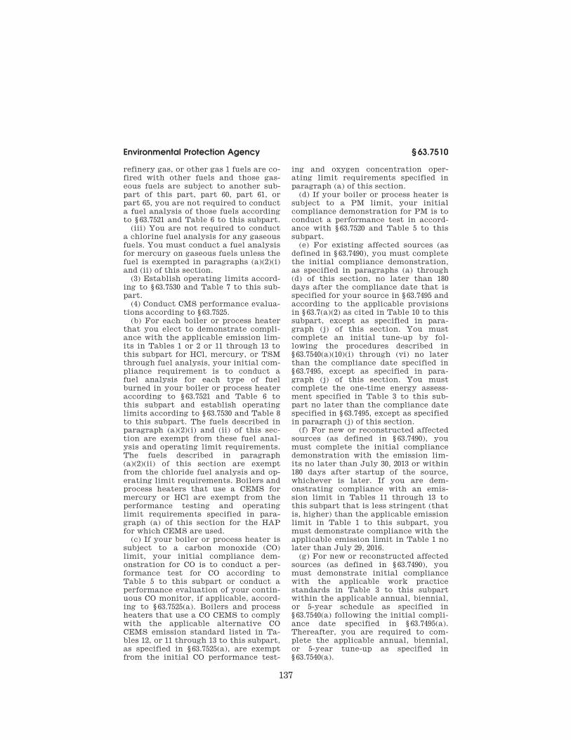
137
Environmental Protection Agency § 63.7510
refinery gas, or other gas 1 fuels are co-
fired with other fuels and those gas-
eous fuels are subject to another sub-
part of this part, part 60, part 61, or
part 65, you are not required to conduct
a fuel analysis of those fuels according
to § 63.7521 and Table 6 to this subpart.
(iii) You are not required to conduct
a chlorine fuel analysis for any gaseous
fuels. You must conduct a fuel analysis
for mercury on gaseous fuels unless the
fuel is exempted in paragraphs (a)(2)(i)
and (ii) of this section.
(3) Establish operating limits accord-
ing to § 63.7530 and Table 7 to this sub-
part.
(4) Conduct CMS performance evalua-
tions according to § 63.7525.
(b) For each boiler or process heater
that you elect to demonstrate compli-
ance with the applicable emission lim-
its in Tables 1 or 2 or 11 through 13 to
this subpart for HCl, mercury, or TSM
through fuel analysis, your initial com-
pliance requirement is to conduct a
fuel analysis for each type of fuel
burned in your boiler or process heater
according to § 63.7521 and Table 6 to
this subpart and establish operating
limits according to § 63.7530 and Table 8
to this subpart. The fuels described in
paragraph (a)(2)(i) and (ii) of this sec-
tion are exempt from these fuel anal-
ysis and operating limit requirements.
The fuels described in paragraph
(a)(2)(ii) of this section are exempt
from the chloride fuel analysis and op-
erating limit requirements. Boilers and
process heaters that use a CEMS for
mercury or HCl are exempt from the
performance testing and operating
limit requirements specified in para-
graph (a) of this section for the HAP
for which CEMS are used.
(c) If your boiler or process heater is
subject to a carbon monoxide (CO)
limit, your initial compliance dem-
onstration for CO is to conduct a per-
formance test for CO according to
Table 5 to this subpart or conduct a
performance evaluation of your contin-
uous CO monitor, if applicable, accord-
ing to § 63.7525(a). Boilers and process
heaters that use a CO CEMS to comply
with the applicable alternative CO
CEMS emission standard listed in Ta-
bles 12, or 11 through 13 to this subpart,
as specified in § 63.7525(a), are exempt
from the initial CO performance test-
ing and oxygen concentration oper-
ating limit requirements specified in
paragraph (a) of this section.
(d) If your boiler or process heater is
subject to a PM limit, your initial
compliance demonstration for PM is to
conduct a performance test in accord-
ance with § 63.7520 and Table 5 to this
subpart.
(e) For existing affected sources (as
defined in § 63.7490), you must complete
the initial compliance demonstration,
as specified in paragraphs (a) through
(d) of this section, no later than 180
days after the compliance date that is
specified for your source in § 63.7495 and
according to the applicable provisions
in § 63.7(a)(2) as cited in Table 10 to this
subpart, except as specified in para-
graph (j) of this section. You must
complete an initial tune-up by fol-
lowing the procedures described in
§ 63.7540(a)(10)(i) through (vi) no later
than the compliance date specified in
§ 63.7495, except as specified in para-
graph (j) of this section. You must
complete the one-time energy assess-
ment specified in Table 3 to this sub-
part no later than the compliance date
specified in § 63.7495, except as specified
in paragraph (j) of this section.
(f) For new or reconstructed affected
sources (as defined in § 63.7490), you
must complete the initial compliance
demonstration with the emission lim-
its no later than July 30, 2013 or within
180 days after startup of the source,
whichever is later. If you are dem-
onstrating compliance with an emis-
sion limit in Tables 11 through 13 to
this subpart that is less stringent (that
is, higher) than the applicable emission
limit in Table 1 to this subpart, you
must demonstrate compliance with the
applicable emission limit in Table 1 no
later than July 29, 2016.
(g) For new or reconstructed affected
sources (as defined in § 63.7490), you
must demonstrate initial compliance
with the applicable work practice
standards in Table 3 to this subpart
within the applicable annual, biennial,
or 5-year schedule as specified in
§ 63.7540(a) following the initial compli-
ance date specified in § 63.7495(a).
Thereafter, you are required to com-
plete the applicable annual, biennial,
or 5-year tune-up as specified in
§ 63.7540(a).
VerDate Sep<11>2014 13:42 Oct 28, 2014 Jkt 232162 PO 00000 Frm 00147 Fmt 8010 Sfmt 8010 Y:\SGML\232162.XXX 232162wre
ier-
avile
s on
DS
K5T
PT
VN
1PR
OD
with
CF
R

138
40 CFR Ch. I (7–1–14 Edition) § 63.7515
(h) For affected sources (as defined in § 63.7490) that ceased burning solid waste consistent with § 63.7495(e) and for which the initial compliance date has passed, you must demonstrate compliance within 60 days of the effec-tive date of the waste-to-fuel switch. If you have not conducted your compli-ance demonstration for this subpart within the previous 12 months, you must complete all compliance dem-onstrations for this subpart before you commence or recommence combustion of solid waste.
(i) For an existing EGU that becomes subject after January 31, 2013, you must demonstrate compliance within 180 days after becoming an affected source.
(j) For existing affected sources (as defined in § 63.7490) that have not oper-
ated between the effective date of the
rule and the compliance date that is
specified for your source in § 63.7495,
you must complete the initial compli-
ance demonstration, if subject to the
emission limits in Table 2 to this sub-
part, as specified in paragraphs (a)
through (d) of this section, no later
than 180 days after the re-start of the
affected source and according to the
applicable provisions in § 63.7(a)(2) as
cited in Table 10 to this subpart. You
must complete an initial tune-up by
following the procedures described in
§ 63.7540(a)(10)(i) through (vi) no later
than 30 days after the re-start of the
affected source and, if applicable, com-
plete the one-time energy assessment
specified in Table 3 to this subpart, no
later than the compliance date speci-
fied in § 63.7495.
[78 FR 7164, Jan. 31, 2013]
§ 63.7515 When must I conduct subse-quent performance tests, fuel anal-yses, or tune-ups?
(a) You must conduct all applicable
performance tests according to § 63.7520
on an annual basis, except as specified
in paragraphs (b) through (e), (g), and
(h) of this section. Annual performance
tests must be completed no more than
13 months after the previous perform-
ance test, except as specified in para-
graphs (b) through (e), (g), and (h) of
this section. (b) If your performance tests for a
given pollutant for at least 2 consecu-
tive years show that your emissions
are at or below 75 percent of the emis-
sion limit (or, in limited instances as
specified in Tables 1 and 2 or 11
through 13 to this subpart, at or below
the emission limit) for the pollutant,
and if there are no changes in the oper-
ation of the individual boiler or process
heater or air pollution control equip-
ment that could increase emissions,
you may choose to conduct perform-
ance tests for the pollutant every third
year. Each such performance test must
be conducted no more than 37 months
after the previous performance test. If
you elect to demonstrate compliance
using emission averaging under
§ 63.7522, you must continue to conduct
performance tests annually. The re-
quirement to test at maximum chlo-
ride input level is waived unless the
stack test is conducted for HCl. The re-
quirement to test at maximum mer-
cury input level is waived unless the
stack test is conducted for mercury.
The requirement to test at maximum
TSM input level is waived unless the
stack test is conducted for TSM.
(c) If a performance test shows emis-
sions exceeded the emission limit or 75
percent of the emission limit (as speci-
fied in Tables 1 and 2 or 11 through 13
to this subpart) for a pollutant, you
must conduct annual performance tests
for that pollutant until all perform-
ance tests over a consecutive 2-year pe-
riod meet the required level (at or
below 75 percent of the emission limit,
as specified in Tables 1 and 2 or 11
through 13 to this subpart).
(d) If you are required to meet an ap-
plicable tune-up work practice stand-
ard, you must conduct an annual, bien-
nial, or 5-year performance tune-up ac-
cording to § 63.7540(a)(10), (11), or (12),
respectively. Each annual tune-up
specified in § 63.7540(a)(10) must be no
more than 13 months after the previous
tune-up. Each biennial tune-up speci-
fied in § 63.7540(a)(11) must be con-
ducted no more than 25 months after
the previous tune-up. Each 5-year tune-
up specified in § 63.7540(a)(12) must be
conducted no more than 61 months
after the previous tune-up. For a new
or reconstructed affected source (as de-
fined in § 63.7490), the first annual, bien-
nial, or 5-year tune-up must be no later
than 13 months, 25 months, or 61
VerDate Sep<11>2014 13:42 Oct 28, 2014 Jkt 232162 PO 00000 Frm 00148 Fmt 8010 Sfmt 8010 Y:\SGML\232162.XXX 232162wre
ier-
avile
s on
DS
K5T
PT
VN
1PR
OD
with
CF
R

139
Environmental Protection Agency § 63.7520
months, respectively, after the initial
startup of the new or reconstructed af-
fected source.
(e) If you demonstrate compliance
with the mercury, HCl, or TSM based
on fuel analysis, you must conduct a
monthly fuel analysis according to
§ 63.7521 for each type of fuel burned
that is subject to an emission limit in
Tables 1, 2, or 11 through 13 to this sub-
part. You may comply with this
monthly requirement by completing
the fuel analysis any time within the
calendar month as long as the analysis
is separated from the previous analysis
by at least 14 calendar days. If you
burn a new type of fuel, you must con-
duct a fuel analysis before burning the
new type of fuel in your boiler or proc-
ess heater. You must still meet all ap-
plicable continuous compliance re-
quirements in § 63.7540. If each of 12
consecutive monthly fuel analyses
demonstrates 75 percent or less of the
compliance level, you may decrease the
fuel analysis frequency to quarterly for
that fuel. If any quarterly sample ex-
ceeds 75 percent of the compliance
level or you begin burning a new type
of fuel, you must return to monthly
monitoring for that fuel, until 12
months of fuel analyses are again less
than 75 percent of the compliance
level.
(f) You must report the results of
performance tests and the associated
fuel analyses within 60 days after the
completion of the performance tests.
This report must also verify that the
operating limits for each boiler or
process heater have not changed or
provide documentation of revised oper-
ating limits established according to
§ 63.7530 and Table 7 to this subpart, as
applicable. The reports for all subse-
quent performance tests must include
all applicable information required in
§ 63.7550.
(g) For affected sources (as defined in
§ 63.7490) that have not operated since
the previous compliance demonstration
and more than one year has passed
since the previous compliance dem-
onstration, you must complete the sub-
sequent compliance demonstration, if
subject to the emission limits in Ta-
bles 1, 2, or 11 through 13 to this sub-
part, no later than 180 days after the
re-start of the affected source and ac-
cording to the applicable provisions in
§ 63.7(a)(2) as cited in Table 10 to this
subpart. You must complete a subse-
quent tune-up by following the proce-
dures described in § 63.7540(a)(10)(i)
through (vi) and the schedule described
in § 63.7540(a)(13) for units that are not
operating at the time of their sched-
uled tune-up.
(h) If your affected boiler or process
heater is in the unit designed to burn
light liquid subcategory and you com-
bust ultra low sulfur liquid fuel, you do
not need to conduct further perform-
ance tests if the pollutants measured
during the initial compliance perform-
ance tests meet the emission limits in
Tables 1 or 2 of this subpart providing
you demonstrate ongoing compliance
with the emissions limits by moni-
toring and recording the type of fuel
combusted on a monthly basis. If you
intend to use a fuel other than ultra
low sulfur liquid fuel, natural gas, re-
finery gas, or other gas 1 fuel, you
must conduct new performance tests
within 60 days of burning the new fuel
type.
(i) If you operate a CO CEMS that
meets the Performance Specifications
outlined in § 63.7525(a)(3) of this subpart
to demonstrate compliance with the
applicable alternative CO CEMS emis-
sion standard listed in Tables 1, 2, or 11
through 13 to this subpart, you are not
required to conduct CO performance
tests and are not subject to the oxygen
concentration operating limit require-
ment specified in § 63.7510(a).
[78 FR 7165, Jan. 31, 2013]
§ 63.7520 What stack tests and proce-dures must I use?
(a) You must conduct all perform-
ance tests according to § 63.7(c), (d), (f),
and (h). You must also develop a site-
specific stack test plan according to
the requirements in § 63.7(c). You shall
conduct all performance tests under
such conditions as the Administrator
specifies to you based on the represent-
ative performance of each boiler or
process heater for the period being
tested. Upon request, you shall make
available to the Administrator such
records as may be necessary to deter-
mine the conditions of the performance
tests.
VerDate Sep<11>2014 13:42 Oct 28, 2014 Jkt 232162 PO 00000 Frm 00149 Fmt 8010 Sfmt 8010 Y:\SGML\232162.XXX 232162wre
ier-
avile
s on
DS
K5T
PT
VN
1PR
OD
with
CF
R

140
40 CFR Ch. I (7–1–14 Edition) § 63.7521
(b) You must conduct each perform-
ance test according to the require-
ments in Table 5 to this subpart.
(c) You must conduct each perform-
ance test under the specific conditions
listed in Tables 5 and 7 to this subpart.
You must conduct performance tests at
representative operating load condi-
tions while burning the type of fuel or
mixture of fuels that has the highest
content of chlorine and mercury, and
TSM if you are opting to comply with
the TSM alternative standard and you
must demonstrate initial compliance
and establish your operating limits
based on these performance tests.
These requirements could result in the
need to conduct more than one per-
formance test. Following each perform-
ance test and until the next perform-
ance test, you must comply with the
operating limit for operating load con-
ditions specified in Table 4 to this sub-
part.
(d) You must conduct a minimum of
three separate test runs for each per-
formance test required in this section,
as specified in § 63.7(e)(3). Each test run
must comply with the minimum appli-
cable sampling times or volumes speci-
fied in Tables 1 and 2 or 11 through 13
to this subpart.
(e) To determine compliance with the
emission limits, you must use the F-
Factor methodology and equations in
sections 12.2 and 12.3 of EPA Method 19
at 40 CFR part 60, appendix A–7 of this
chapter to convert the measured par-
ticulate matter (PM) concentrations,
the measured HCl concentrations, the
measured mercury concentrations, and
the measured TSM concentrations that
result from the performance test to
pounds per million Btu heat input
emission rates.
(f) Except for a 30-day rolling average
based on CEMS (or sorbent trap moni-
toring system) data, if measurement
results for any pollutant are reported
as below the method detection level
(e.g., laboratory analytical results for
one or more sample components are
below the method defined analytical
detection level), you must use the
method detection level as the meas-
ured emissions level for that pollutant
in calculating compliance. The meas-
ured result for a multiple component
analysis (e.g., analytical values for
multiple Method 29 fractions both for
individual HAP metals and for total
HAP metals) may include a combina-
tion of method detection level data and
analytical data reported above the
method detection level.
[76 FR 15664, Mar. 21, 2011, as amended at 78
FR 7166, Jan. 31, 2013]
§ 63.7521 What fuel analyses, fuel spec-ification, and procedures must I use?
(a) For solid and liquid fuels, you
must conduct fuel analyses for chloride
and mercury according to the proce-
dures in paragraphs (b) through (e) of
this section and Table 6 to this sub-
part, as applicable. For solid fuels and
liquid fuels, you must also conduct fuel
analyses for TSM if you are opting to
comply with the TSM alternative
standard. For gas 2 (other) fuels, you
must conduct fuel analyses for mer-
cury according to the procedures in
paragraphs (b) through (e) of this sec-
tion and Table 6 to this subpart, as ap-
plicable. (For gaseous fuels, you may
not use fuel analyses to comply with
the TSM alternative standard or the
HCl standard.) For purposes of com-
plying with this section, a fuel gas sys-
tem that consists of multiple gaseous
fuels collected and mixed with each
other is considered a single fuel type
and sampling and analysis is only re-
quired on the combined fuel gas system
that will feed the boiler or process
heater. Sampling and analysis of the
individual gaseous streams prior to
combining is not required. You are not
required to conduct fuel analyses for
fuels used for only startup, unit shut-
down, and transient flame stability
purposes. You are required to conduct
fuel analyses only for fuels and units
that are subject to emission limits for
mercury, HCl, or TSM in Tables 1 and
2 or 11 through 13 to this subpart. Gas-
eous and liquid fuels are exempt from
the sampling requirements in para-
graphs (c) and (d) of this section and
Table 6 to this subpart.
(b) You must develop a site-specific
fuel monitoring plan according to the
following procedures and requirements
in paragraphs (b)(1) and (2) of this sec-
tion, if you are required to conduct fuel
analyses as specified in § 63.7510.
VerDate Sep<11>2014 13:42 Oct 28, 2014 Jkt 232162 PO 00000 Frm 00150 Fmt 8010 Sfmt 8010 Y:\SGML\232162.XXX 232162wre
ier-
avile
s on
DS
K5T
PT
VN
1PR
OD
with
CF
R

141
Environmental Protection Agency § 63.7521
(1) If you intend to use an alternative
analytical method other than those re-
quired by Table 6 to this subpart, you
must submit the fuel analysis plan to
the Administrator for review and ap-
proval no later than 60 days before the
date that you intend to conduct the
initial compliance demonstration de-
scribed in § 63.7510.
(2) You must include the information
contained in paragraphs (b)(2)(i)
through (vi) of this section in your fuel
analysis plan.
(i) The identification of all fuel types
anticipated to be burned in each boiler
or process heater.
(ii) For each anticipated fuel type,
the notification of whether you or a
fuel supplier will be conducting the
fuel analysis.
(iii) For each anticipated fuel type, a
detailed description of the sample loca-
tion and specific procedures to be used
for collecting and preparing the com-
posite samples if your procedures are
different from paragraph (c) or (d) of
this section. Samples should be col-
lected at a location that most accu-
rately represents the fuel type, where
possible, at a point prior to mixing
with other dissimilar fuel types.
(iv) For each anticipated fuel type,
the analytical methods from Table 6,
with the expected minimum detection
levels, to be used for the measurement
of chlorine or mercury.
(v) If you request to use an alter-
native analytical method other than
those required by Table 6 to this sub-
part, you must also include a detailed
description of the methods and proce-
dures that you are proposing to use.
Methods in Table 6 shall be used until
the requested alternative is approved.
(vi) If you will be using fuel analysis
from a fuel supplier in lieu of site-spe-
cific sampling and analysis, the fuel
supplier must use the analytical meth-
ods required by Table 6 to this subpart.
(c) At a minimum, you must obtain
three composite fuel samples for each
fuel type according to the procedures
in paragraph (c)(1) or (2) of this section,
or the methods listed in Table 6 to this
subpart, or use an automated sampling
mechanism that provides representa-
tive composite fuel samples for each
fuel type that includes both coarse and
fine material.
(1) If sampling from a belt (or screw)
feeder, collect fuel samples according
to paragraphs (c)(1)(i) and (ii) of this
section.
(i) Stop the belt and withdraw a 6-
inch wide sample from the full cross-
section of the stopped belt to obtain a
minimum two pounds of sample. You
must collect all the material (fines and
coarse) in the full cross-section. You
must transfer the sample to a clean
plastic bag.
(ii) Each composite sample will con-
sist of a minimum of three samples col-
lected at approximately equal one-hour
intervals during the testing period for
sampling during performance stack
testing. For monthly sampling, each
composite sample shall be collected at
approximately equal 10-day intervals
during the month.
(2) If sampling from a fuel pile or
truck, you must collect fuel samples
according to paragraphs (c)(2)(i)
through (iii) of this section.
(i) For each composite sample, you
must select a minimum of five sam-
pling locations uniformly spaced over
the surface of the pile.
(ii) At each sampling site, you must
dig into the pile to a uniform depth of
approximately 18 inches. You must in-
sert a clean shovel into the hole and
withdraw a sample, making sure that
large pieces do not fall off during sam-
pling; use the same shovel to collect all
samples.
(iii) You must transfer all samples to
a clean plastic bag for further proc-
essing.
(d) You must prepare each composite
sample according to the procedures in
paragraphs (d)(1) through (7) of this
section.
(1) You must thoroughly mix and
pour the entire composite sample over
a clean plastic sheet.
(2) You must break large sample
pieces (e.g., larger than 3 inches) into
smaller sizes.
(3) You must make a pie shape with
the entire composite sample and sub-
divide it into four equal parts.
(4) You must separate one of the
quarter samples as the first subset.
(5) If this subset is too large for
grinding, you must repeat the proce-
dure in paragraph (d)(3) of this section
VerDate Sep<11>2014 13:42 Oct 28, 2014 Jkt 232162 PO 00000 Frm 00151 Fmt 8010 Sfmt 8010 Y:\SGML\232162.XXX 232162wre
ier-
avile
s on
DS
K5T
PT
VN
1PR
OD
with
CF
R

142
40 CFR Ch. I (7–1–14 Edition) § 63.7521
with the quarter sample and obtain a
one-quarter subset from this sample.
(6) You must grind the sample in a
mill.
(7) You must use the procedure in
paragraph (d)(3) of this section to ob-
tain a one-quarter subsample for anal-
ysis. If the quarter sample is too large,
subdivide it further using the same
procedure.
(e) You must determine the con-
centration of pollutants in the fuel
(mercury and/or chlorine and/or TSM)
in units of pounds per million Btu of
each composite sample for each fuel
type according to the procedures in
Table 6 to this subpart, for use in
Equations 7, 8, and 9 of this subpart.
(f) To demonstrate that a gaseous
fuel other than natural gas or refinery
gas qualifies as an other gas 1 fuel, as
defined in § 63.7575, you must conduct a
fuel specification analyses for mercury
according to the procedures in para-
graphs (g) through (i) of this section
and Table 6 to this subpart, as applica-
ble, except as specified in paragraph
(f)(1) through (4) of this section.
(1) You are not required to conduct
the fuel specification analyses in para-
graphs (g) through (i) of this section
for natural gas or refinery gas.
(2) You are not required to conduct
the fuel specification analyses in para-
graphs (g) through (i) of this section
for gaseous fuels that are subject to an-
other subpart of this part, part 60, part
61, or part 65.
(3) You are not required to conduct
the fuel specification analyses in para-
graphs (g) through (i) of this section on
gaseous fuels for units that are com-
plying with the limits for units de-
signed to burn gas 2 (other) fuels.
(4) You are not required to conduct
the fuel specification analyses in para-
graphs (g) through (i) of this section
for gas streams directly derived from
natural gas at natural gas production
sites or natural gas plants.
(g) You must develop and submit a
site-specific fuel analysis plan for
other gas 1 fuels to the EPA Adminis-
trator for review and approval accord-
ing to the following procedures and re-
quirements in paragraphs (g)(1) and (2)
of this section.
(1) If you intend to use an alternative
analytical method other than those re-
quired by Table 6 to this subpart, you
must submit the fuel analysis plan to
the Administrator for review and ap-
proval no later than 60 days before the
date that you intend to conduct the
initial compliance demonstration de-
scribed in § 63.7510.
(2) You must include the information
contained in paragraphs (g)(2)(i)
through (vi) of this section in your fuel
analysis plan.
(i) The identification of all gaseous
fuel types other than those exempted
from fuel specification analysis under
(f)(1) through (3) of this section antici-
pated to be burned in each boiler or
process heater.
(ii) For each anticipated fuel type,
the notification of whether you or a
fuel supplier will be conducting the
fuel specification analysis.
(iii) For each anticipated fuel type, a
detailed description of the sample loca-
tion and specific procedures to be used
for collecting and preparing the sam-
ples if your procedures are different
from the sampling methods contained
in Table 6 to this subpart. Samples
should be collected at a location that
most accurately represents the fuel
type, where possible, at a point prior to
mixing with other dissimilar fuel
types. If multiple boilers or process
heaters are fueled by a common fuel
stream it is permissible to conduct a
single gas specification at the common
point of gas distribution.
(iv) For each anticipated fuel type,
the analytical methods from Table 6 to
this subpart, with the expected min-
imum detection levels, to be used for
the measurement of mercury.
(v) If you request to use an alter-
native analytical method other than
those required by Table 6 to this sub-
part, you must also include a detailed
description of the methods and proce-
dures that you are proposing to use.
Methods in Table 6 to this subpart
shall be used until the requested alter-
native is approved.
(vi) If you will be using fuel analysis
from a fuel supplier in lieu of site-spe-
cific sampling and analysis, the fuel
supplier must use the analytical meth-
ods required by Table 6 to this subpart.
(h) You must obtain a single fuel
sample for each fuel type according to
VerDate Sep<11>2014 13:42 Oct 28, 2014 Jkt 232162 PO 00000 Frm 00152 Fmt 8010 Sfmt 8010 Y:\SGML\232162.XXX 232162wre
ier-
avile
s on
DS
K5T
PT
VN
1PR
OD
with
CF
R

143
Environmental Protection Agency § 63.7522
the sampling procedures listed in Table
6 for fuel specification of gaseous fuels.
(i) You must determine the con-
centration in the fuel of mercury, in
units of microgram per cubic meter,
dry basis, of each sample for each other
gas 1 fuel type according to the proce-
dures in Table 6 to this subpart.
[78 FR 7167, Jan. 31, 2013]
§ 63.7522 Can I use emissions aver-aging to comply with this subpart?
(a) As an alternative to meeting the
requirements of § 63.7500 for PM (or
TSM), HCl, or mercury on a boiler or
process heater-specific basis, if you
have more than one existing boiler or
process heater in any subcategories lo-
cated at your facility, you may dem-
onstrate compliance by emissions aver-
aging, if your averaged emissions are
not more than 90 percent of the appli-
cable emission limit, according to the
procedures in this section. You may
not include new boilers or process heat-
ers in an emissions average.
(b) For a group of two or more exist-
ing boilers or process heaters in the
same subcategory that each vent to a
separate stack, you may average PM
(or TSM), HCl, or mercury emissions
among existing units to demonstrate
compliance with the limits in Table 2
to this subpart as specified in para-
graph (b)(1) through (3) of this section,
if you satisfy the requirements in para-
graphs (c) through (g) of this section.
(1) You may average units using a
CEMS or PM CPMS for demonstrating
compliance.
(2) For mercury and HCl, averaging is
allowed as follows:
(i) You may average among units in
any of the solid fuel subcategories.
(ii) You may average among units in
any of the liquid fuel subcategories.
(iii) You may average among units in
a subcategory of units designed to burn
gas 2 (other) fuels.
(iv) You may not average across the
units designed to burn liquid, units de-
signed to burn solid fuel, and units de-
signed to burn gas 2 (other) subcat-
egories.
(3) For PM (or TSM), averaging is
only allowed between units within each
of the following subcategories and you
may not average across subcategories:
(i) Units designed to burn coal/solid
fossil fuel.
(ii) Stokers/sloped grate/other units
designed to burn kiln dried biomass/
bio-based solids.
(iii) Stokers/sloped grate/other units
designed to burn wet biomass/bio-based
solids.
(iv) Fluidized bed units designed to
burn biomass/bio-based solid.
(v) Suspension burners designed to
burn biomass/bio-based solid.
(vi) Dutch ovens/pile burners de-
signed to burn biomass/bio-based solid.
(vii) Fuel Cells designed to burn bio-
mass/bio-based solid.
(viii) Hybrid suspension/grate burners
designed to burn wet biomass/bio-based
solid.
(ix) Units designed to burn heavy liq-
uid fuel.
(x) Units designed to burn light liq-
uid fuel.
(xi) Units designed to burn liquid fuel
that are non-continental units.
(xii) Units designed to burn gas 2
(other) gases.
(c) For each existing boiler or process
heater in the averaging group, the
emission rate achieved during the ini-
tial compliance test for the HAP being
averaged must not exceed the emission
level that was being achieved on Janu-
ary 31, 2013 or the control technology
employed during the initial compliance
test must not be less effective for the
HAP being averaged than the control
technology employed on January 31,
2013.
(d) The averaged emissions rate from
the existing boilers and process heaters
participating in the emissions aver-
aging option must not exceed 90 per-
cent of the limits in Table 2 to this
subpart at all times the affected units
are operating following the compliance
date specified in § 63.7495.
(e) You must demonstrate initial
compliance according to paragraph
(e)(1) or (2) of this section using the
maximum rated heat input capacity or
maximum steam generation capacity
of each unit and the results of the ini-
tial performance tests or fuel analysis.
(1) You must use Equation 1a or 1b or
1c of this section to demonstrate that
the PM (or TSM), HCl, or mercury
emissions from all existing units par-
ticipating in the emissions averaging
VerDate Sep<11>2014 13:42 Oct 28, 2014 Jkt 232162 PO 00000 Frm 00153 Fmt 8010 Sfmt 8010 Y:\SGML\232162.XXX 232162wre
ier-
avile
s on
DS
K5T
PT
VN
1PR
OD
with
CF
R

144
40 CFR Ch. I (7–1–14 Edition) § 63.7522
option for that pollutant do not exceed
the emission limits in Table 2 to this
subpart. Use Equation 1a if you are
complying with the emission limits on
a heat input basis, use Equation 1b if
you are complying with the emission
limits on a steam generation (output)
basis, and use Equation 1c if you are
complying with the emission limits on
a electric generation (output) basis.
Where:
AveWeightedEmissions = Average weighted
emissions for PM (or TSM), HCl, or mer-
cury, in units of pounds per million Btu
of heat input.
Er = Emission rate (as determined during the
initial compliance demonstration) of PM
(or TSM), HCl, or mercury from unit, i,
in units of pounds per million Btu of heat
input. Determine the emission rate for
PM (or TSM), HCl, or mercury by per-
formance testing according to Table 5 to
this subpart, or by fuel analysis for HCl
or mercury or TSM using the applicable
equation in § 63.7530(c).
Hm = Maximum rated heat input capacity of
unit, i, in units of million Btu per hour.
n = Number of units participating in the
emissions averaging option.
1.1 = Required discount factor.
Where:
AveWeightedEmissions = Average weighted
emissions for PM (or TSM), HCl, or mer-
cury, in units of pounds per million Btu
of steam output.
Er = Emission rate (as determined during the
initial compliance demonstration) of PM
(or TSM), HCl, or mercury from unit, i,
in units of pounds per million Btu of
steam output. Determine the emission
rate for PM (or TSM), HCl, or mercury
by performance testing according to
Table 5 to this subpart, or by fuel anal-
ysis for HCl or mercury or TSM using the
applicable equation in § 63.7530(c). If you
are taking credit for energy conservation
measures from a unit according to
§ 63.7533, use the adjusted emission level
for that unit, Eadj, determined according
to § 63.7533 for that unit.
So = Maximum steam output capacity of
unit, i, in units of million Btu per hour,
as defined in § 63.7575.
n = Number of units participating in the
emissions averaging option.
1.1 = Required discount factor.
Where:
AveWeightedEmissions = Average weighted
emissions for PM (or TSM), HCl, or mer-
cury, in units of pounds per megawatt
hour.
Er = Emission rate (as determined during the
initial compliance demonstration) of PM
(or TSM), HCl, or mercury from unit, i,
in units of pounds per megawatt hour.
Determine the emission rate for PM (or
TSM), HCl, or mercury by performance
testing according to Table 5 to this sub-
part, or by fuel analysis for HCl or mer-
cury or TSM using the applicable equa-
tion in § 63.7530(c). If you are taking cred-
it for energy conservation measures from
a unit according to § 63.7533, use the ad-
justed emission level for that unit, Eadj,
determined according to § 63.7533 for that
unit.
Eo = Maximum electric generating output
capacity of unit, i, in units of megawatt
hour, as defined in § 63.7575.
VerDate Sep<11>2014 13:42 Oct 28, 2014 Jkt 232162 PO 00000 Frm 00154 Fmt 8010 Sfmt 8010 Y:\SGML\232162.XXX 232162 ER
31JA
13.0
04<
/GP
H>
ER
31JA
13.0
05<
/GP
H>
ER
31JA
13.0
06<
/GP
H>
wre
ier-
avile
s on
DS
K5T
PT
VN
1PR
OD
with
CF
R

145
Environmental Protection Agency § 63.7522
n = Number of units participating in the
emissions averaging option.
1.1 = Required discount factor.
(2) If you are not capable of deter-
mining the maximum rated heat input
capacity of one or more boilers that
generate steam, you may use Equation
2 of this section as an alternative to
using Equation 1a of this section to
demonstrate that the PM (or TSM),
HCl, or mercury emissions from all ex-
isting units participating in the emis-
sions averaging option do not exceed
the emission limits for that pollutant
in Table 2 to this subpart that are in
pounds per million Btu of heat input.
Where:
AveWeightedEmissions = Average weighted
emission level for PM (or TSM), HCl, or
mercury, in units of pounds per million
Btu of heat input.
Er = Emission rate (as determined during the
most recent compliance demonstration)
of PM (or TSM), HCl, or mercury from
unit, i, in units of pounds per million Btu
of heat input. Determine the emission
rate for PM (or TSM), HCl, or mercury
by performance testing according to
Table 5 to this subpart, or by fuel anal-
ysis for HCl or mercury or TSM using the
applicable equation in § 63.7530(c).
Sm = Maximum steam generation capacity
by unit, i, in units of pounds per hour.
Cfi = Conversion factor, calculated from the
most recent compliance test, in units of
million Btu of heat input per pounds of
steam generated for unit, i.
1.1 = Required discount factor.
(f) After the initial compliance dem-
onstration described in paragraph (e) of
this section, you must demonstrate
compliance on a monthly basis deter-
mined at the end of every month (12
times per year) according to para-
graphs (f)(1) through (3) of this section.
The first monthly period begins on the
compliance date specified in § 63.7495. If
the affected source elects to collect
monthly data for up the 11 months pre-
ceding the first monthly period, these
additional data points can be used to
compute the 12-month rolling average
in paragraph (f)(3) of this section.
(1) For each calendar month, you
must use Equation 3a or 3b or 3c of this
section to calculate the average
weighted emission rate for that month.
Use Equation 3a and the actual heat
input for the month for each existing
unit participating in the emissions
averaging option if you are complying
with emission limits on a heat input
basis. Use Equation 3b and the actual
steam generation for the month if you
are complying with the emission limits
on a steam generation (output) basis.
Use Equation 3c and the actual steam
generation for the month if you are
complying with the emission limits on
a electrical generation (output) basis.
Where: AveWeightedEmissions = Average weighted
emission level for PM (or TSM), HCl, or
mercury, in units of pounds per million
Btu of heat input, for that calendar
month. Er = Emission rate (as determined during the
most recent compliance demonstration)
of PM (or TSM), HCl, or mercury from
unit, i, in units of pounds per million Btu
of heat input. Determine the emission
rate for PM (or TSM), HCl, or mercury
by performance testing according to
Table 5 to this subpart, or by fuel anal-
ysis for HCl or mercury or TSM accord-
ing to Table 6 to this subpart.
Hb = The heat input for that calendar month
to unit, i, in units of million Btu.
n = Number of units participating in the
emissions averaging option.
1.1 = Required discount factor.
VerDate Sep<11>2014 13:42 Oct 28, 2014 Jkt 232162 PO 00000 Frm 00155 Fmt 8010 Sfmt 8010 Y:\SGML\232162.XXX 232162 ER
31JA
13.0
07<
/GP
H>
ER
31JA
13.0
08<
/GP
H>
wre
ier-
avile
s on
DS
K5T
PT
VN
1PR
OD
with
CF
R

146
40 CFR Ch. I (7–1–14 Edition) § 63.7522
Where: AveWeightedEmissions = Average weighted
emission level for PM (or TSM), HCl, or
mercury, in units of pounds per million
Btu of steam output, for that calendar
month. Er = Emission rate (as determined during the
most recent compliance demonstration)
of PM (or TSM), HCl, or mercury from
unit, i, in units of pounds per million Btu
of steam output. Determine the emission
rate for PM (or TSM), HCl, or mercury
by performance testing according to
Table 5 to this subpart, or by fuel anal-
ysis for HCl or mercury or TSM accord-
ing to Table 6 to this subpart. If you are
taking credit for energy conservation
measures from a unit according to
§ 63.7533, use the adjusted emission level
for that unit, Eadj, determined according
to § 63.7533 for that unit.
So = The steam output for that calendar
month from unit, i, in units of million
Btu, as defined in § 63.7575.
n = Number of units participating in the
emissions averaging option.
1.1 = Required discount factor.
Where: AveWeightedEmissions = Average weighted
emission level for PM (or TSM), HCl, or
mercury, in units of pounds per mega-
watt hour, for that calendar month. Er = Emission rate (as determined during the
most recent compliance demonstration)
of PM (or TSM), HCl, or mercury from
unit, i, in units of pounds per megawatt
hour. Determine the emission rate for
PM (or TSM), HCl, or mercury by per-
formance testing according to Table 5 to
this subpart, or by fuel analysis for HCl
or mercury or TSM according to Table 6
to this subpart. If you are taking credit
for energy conservation measures from a
unit according to § 63.7533, use the ad-
justed emission level for that unit, Eadj,
determined according to § 63.7533 for that
unit.
Eo = The electric generating output for that
calendar month from unit, i, in units of
megawatt hour, as defined in § 63.7575.
n = Number of units participating in the
emissions averaging option.
1.1 = Required discount factor.
(2) If you are not capable of moni-
toring heat input, you may use Equa-
tion 4 of this section as an alternative
to using Equation 3a of this section to
calculate the average weighted emis-
sion rate using the actual steam gen-
eration from the boilers participating
in the emissions averaging option.
Where:
AveWeightedEmissions = average weighted
emission level for PM (or TSM), HCl, or
mercury, in units of pounds per million
Btu of heat input for that calendar
month.
Er = Emission rate (as determined during the
most recent compliance demonstration
of PM (or TSM), HCl, or mercury from
unit, i, in units of pounds per million Btu
of heat input. Determine the emission
rate for PM (or TSM), HCl, or mercury
by performance testing according to
Table 5 to this subpart, or by fuel anal-
ysis for HCl or mercury or TSM accord-
ing to Table 6 to this subpart.
Sa = Actual steam generation for that cal-
endar month by boiler, i, in units of
pounds.
Cfi = Conversion factor, as calculated during
the most recent compliance test, in units
VerDate Sep<11>2014 13:42 Oct 28, 2014 Jkt 232162 PO 00000 Frm 00156 Fmt 8010 Sfmt 8010 Y:\SGML\232162.XXX 232162 ER
31JA
13.0
09<
/GP
H>
ER
31JA
13.0
10<
/GP
H>
ER
31JA
13.0
11<
/GP
H>
wre
ier-
avile
s on
DS
K5T
PT
VN
1PR
OD
with
CF
R

147
Environmental Protection Agency § 63.7522
of million Btu of heat input per pounds
of steam generated for boiler, i.
1.1 = Required discount factor.
(3) Until 12 monthly weighted aver-
age emission rates have been accumu-
lated, calculate and report only the av-
erage weighted emission rate deter-
mined under paragraph (f)(1) or (2) of
this section for each calendar month.
After 12 monthly weighted average
emission rates have been accumulated,
for each subsequent calendar month,
use Equation 5 of this section to cal-
culate the 12-month rolling average of
the monthly weighted average emis-
sion rates for the current calendar
month and the previous 11 calendar
months.
Where:
Eavg = 12-month rolling average emission
rate, (pounds per million Btu heat input) ERi = Monthly weighted average, for cal-
endar month ‘‘i’’ (pounds per million Btu
heat input), as calculated by paragraph
(f)(1) or (2) of this section.
(g) You must develop, and submit upon request to the applicable Admin-istrator for review and approval, an im-plementation plan for emission aver-aging according to the following proce-dures and requirements in paragraphs (g)(1) through (4) of this section.
(1) You must submit the implementa-tion plan no later than 180 days before the date that the facility intends to demonstrate compliance using the emission averaging option.
(2) You must include the information contained in paragraphs (g)(2)(i) through (vii) of this section in your im-plementation plan for all emission sources included in an emissions aver-age:
(i) The identification of all existing boilers and process heaters in the aver-aging group, including for each either the applicable HAP emission level or the control technology installed as of January 31, 2013 and the date on which
you are requesting emission averaging
to commence; (ii) The process parameter (heat
input or steam generated) that will be
monitored for each averaging group; (iii) The specific control technology
or pollution prevention measure to be
used for each emission boiler or process
heater in the averaging group and the
date of its installation or application.
If the pollution prevention measure re-
duces or eliminates emissions from
multiple boilers or process heaters, the
owner or operator must identify each
boiler or process heater;
(iv) The test plan for the measure-
ment of PM (or TSM), HCl, or mercury
emissions in accordance with the re-
quirements in § 63.7520;
(v) The operating parameters to be
monitored for each control system or
device consistent with § 63.7500 and
Table 4, and a description of how the
operating limits will be determined;
(vi) If you request to monitor an al-
ternative operating parameter pursu-
ant to § 63.7525, you must also include:
(A) A description of the parameter(s)
to be monitored and an explanation of
the criteria used to select the param-
eter(s); and
(B) A description of the methods and
procedures that will be used to dem-
onstrate that the parameter indicates
proper operation of the control device;
the frequency and content of moni-
toring, reporting, and recordkeeping
requirements; and a demonstration, to
the satisfaction of the Administrator,
that the proposed monitoring fre-
quency is sufficient to represent con-
trol device operating conditions; and
(vii) A demonstration that compli-
ance with each of the applicable emis-
sion limit(s) will be achieved under
representative operating load condi-
tions. Following each compliance dem-
onstration and until the next compli-
ance demonstration, you must comply
with the operating limit for operating
load conditions specified in Table 4 to
this subpart.
VerDate Sep<11>2014 13:42 Oct 28, 2014 Jkt 232162 PO 00000 Frm 00157 Fmt 8010 Sfmt 8010 Y:\SGML\232162.XXX 232162 ER
21M
R11
.004
</G
PH
>
wre
ier-
avile
s on
DS
K5T
PT
VN
1PR
OD
with
CF
R

148
40 CFR Ch. I (7–1–14 Edition) § 63.7522
(3) The Administrator shall review
and approve or disapprove the plan ac-
cording to the following criteria:
(i) Whether the content of the plan
includes all of the information speci-
fied in paragraph (g)(2) of this section;
and
(ii) Whether the plan presents suffi-
cient information to determine that
compliance will be achieved and main-
tained.
(4) The applicable Administrator
shall not approve an emission aver-
aging implementation plan containing
any of the following provisions:
(i) Any averaging between emissions
of differing pollutants or between dif-
fering sources; or
(ii) The inclusion of any emission
source other than an existing unit in
the same subcategories.
(h) For a group of two or more exist-
ing affected units, each of which vents
through a single common stack, you
may average PM (or TSM), HCl, or
mercury emissions to demonstrate
compliance with the limits for that
pollutant in Table 2 to this subpart if
you satisfy the requirements in para-
graph (i) or (j) of this section.
(i) For a group of two or more exist-
ing units in the same subcategories,
each of which vents through a common
emissions control system to a common
stack, that does not receive emissions
from units in other subcategories or
categories, you may treat such aver-
aging group as a single existing unit
for purposes of this subpart and comply
with the requirements of this subpart
as if the group were a single unit.
(j) For all other groups of units sub-
ject to the common stack requirements
of paragraph (h) of this section, includ-
ing situations where the exhaust of af-
fected units are each individually con-
trolled and then sent to a common
stack, the owner or operator may elect
to:
(1) Conduct performance tests accord-
ing to procedures specified in § 63.7520
in the common stack if affected units
from other subcategories vent to the
common stack. The emission limits
that the group must comply with are
determined by the use of Equation 6 of
this section.
Where:
En = HAP emission limit, pounds per million
British thermal units (lb/MMBtu), parts
per million (ppm), or nanograms per dry
standard cubic meter (ng/dscm).
ELi = Appropriate emission limit from Table
2 to this subpart for unit i, in units of lb/
MMBtu, ppm or ng/dscm.
Hi = Heat input from unit i, MMBtu.
(2) Conduct performance tests accord-
ing to procedures specified in § 63.7520
in the common stack. If affected units
and non-affected units vent to the com-
mon stack, the non-affected units must
be shut down or vented to a different
stack during the performance test un-
less the facility determines to dem-
onstrate compliance with the non-af-
fected units venting to the stack; and
(3) Meet the applicable operating
limit specified in § 63.7540 and Table 8
to this subpart for each emissions con-
trol system (except that, if each unit
venting to the common stack has an
applicable opacity operating limit,
then a single continuous opacity moni-
toring system may be located in the
common stack instead of in each duct
to the common stack).
(k) The common stack of a group of
two or more existing boilers or process
heaters in the same subcategories sub-
ject to paragraph (h) of this section
may be treated as a separate stack for
purposes of paragraph (b) of this sec-
tion and included in an emissions aver-
aging group subject to paragraph (b) of
this section.
[76 FR 15664, Mar. 21, 2011, as amended at 78
FR 7168, Jan. 31, 2013]
VerDate Sep<11>2014 13:42 Oct 28, 2014 Jkt 232162 PO 00000 Frm 00158 Fmt 8010 Sfmt 8010 Y:\SGML\232162.XXX 232162 ER
31JA
13.0
12<
/GP
H>
wre
ier-
avile
s on
DS
K5T
PT
VN
1PR
OD
with
CF
R

149
Environmental Protection Agency § 63.7525
§ 63.7525 What are my monitoring, in-stallation, operation, and mainte-nance requirements?
(a) If your boiler or process heater is
subject to a CO emission limit in Ta-
bles 1, 2, or 11 through 13 to this sub-
part, you must install, operate, and
maintain an oxygen analyzer system,
as defined in § 63.7575, or install, cer-
tify, operate and maintain continuous
emission monitoring systems for CO
and oxygen according to the procedures
in paragraphs (a)(1) through (7) of this
section.
(1) Install the CO CEMS and oxygen
analyzer by the compliance date speci-
fied in § 63.7495. The CO and oxygen lev-
els shall be monitored at the same lo-
cation at the outlet of the boiler or
process heater.
(2) To demonstrate compliance with
the applicable alternative CO CEMS
emission standard listed in Tables 1, 2,
or 11 through 13 to this subpart, you
must install, certify, operate, and
maintain a CO CEMS and an oxygen
analyzer according to the applicable
procedures under Performance Speci-
fication 4, 4A, or 4B at 40 CFR part 60,
appendix B, the site-specific moni-
toring plan developed according to
§ 63.7505(d), and the requirements in
§ 63.7540(a)(8) and paragraph (a) of this
section. Any boiler or process heater
that has a CO CEMS that is compliant
with Performance Specification 4, 4A,
or 4B at 40 CFR part 60, appendix B, a
site-specific monitoring plan developed
according to § 63.7505(d), and the re-
quirements in § 63.7540(a)(8) and para-
graph (a) of this section must use the
CO CEMS to comply with the applica-
ble alternative CO CEMS emission
standard listed in Tables 1, 2, or 11
through 13 to this subpart.
(i) You must conduct a performance
evaluation of each CO CEMS according
to the requirements in § 63.8(e) and ac-
cording to Performance Specification
4, 4A, or 4B at 40 CFR part 60, appendix
B.
(ii) During each relative accuracy
test run of the CO CEMS, you must be
collect emission data for CO concur-
rently (or within a 30- to 60-minute pe-
riod) by both the CO CEMS and by
Method 10, 10A, or 10B at 40 CFR part
60, appendix A–4. The relative accuracy
testing must be at representative oper-
ating conditions.
(iii) You must follow the quality as-
surance procedures (e.g., quarterly ac-
curacy determinations and daily cali-
bration drift tests) of Procedure 1 of
appendix F to part 60. The measure-
ment span value of the CO CEMS must
be two times the applicable CO emis-
sion limit, expressed as a concentra-
tion.
(iv) Any CO CEMS that does not com-
ply with § 63.7525(a) cannot be used to
meet any requirement in this subpart
to demonstrate compliance with a CO
emission limit listed in Tables 1, 2, or
11 through 13 to this subpart.
(v) For a new unit, complete the ini-
tial performance evaluation no later
than July 30, 2013, or 180 days after the
date of initial startup, whichever is
later. For an existing unit, complete
the initial performance evaluation no
later than July 29, 2016.
(3) Complete a minimum of one cycle
of CO and oxygen CEMS operation
(sampling, analyzing, and data record-
ing) for each successive 15-minute pe-
riod. Collect CO and oxygen data con-
currently. Collect at least four CO and
oxygen CEMS data values representing
the four 15-minute periods in an hour,
or at least two 15-minute data values
during an hour when CEMS calibra-
tion, quality assurance, or mainte-
nance activities are being performed.
(4) Reduce the CO CEMS data as spec-
ified in § 63.8(g)(2).
(5) Calculate one-hour arithmetic
averages, corrected to 3 percent oxygen
from each hour of CO CEMS data in
parts per million CO concentration.
The one-hour arithmetic averages re-
quired shall be used to calculate the 30-
day or 10-day rolling average emis-
sions. Use Equation 19–19 in section
12.4.1 of Method 19 of 40 CFR part 60,
appendix A–7 for calculating the aver-
age CO concentration from the hourly
values.
(6) For purposes of collecting CO
data, operate the CO CEMS as specified
in § 63.7535(b). You must use all the
data collected during all periods in cal-
culating data averages and assessing
compliance, except that you must ex-
clude certain data as specified in
§ 63.7535(c). Periods when CO data are
VerDate Sep<11>2014 13:42 Oct 28, 2014 Jkt 232162 PO 00000 Frm 00159 Fmt 8010 Sfmt 8010 Y:\SGML\232162.XXX 232162wre
ier-
avile
s on
DS
K5T
PT
VN
1PR
OD
with
CF
R

150
40 CFR Ch. I (7–1–14 Edition) § 63.7525
unavailable may constitute monitoring
deviations as specified in § 63.7535(d).
(7) Operate an oxygen trim system
with the oxygen level set no lower than
the lowest hourly average oxygen con-
centration measured during the most
recent CO performance test as the op-
erating limit for oxygen according to
Table 7 to this subpart.
(b) If your boiler or process heater is
in the unit designed to burn coal/solid
fossil fuel subcategory or the unit de-
signed to burn heavy liquid sub-
category and has an average annual
heat input rate greater than 250
MMBtu per hour from solid fossil fuel
and/or heavy liquid, and you dem-
onstrate compliance with the PM limit
instead of the alternative TSM limit,
you must install, certify, maintain,
and operate a PM CPMS monitoring
emissions discharged to the atmos-
phere and record the output of the sys-
tem as specified in paragraphs (b)(1)
through (4) of this section. As an alter-
native to use of a PM CPMS to dem-
onstrate compliance with the PM
limit, you may choose to use a PM
CEMS. If you choose to use a PM
CEMS to demonstrate compliance with
the PM limit instead of the alternative
TSM limit, you must install, certify,
maintain, and operate a PM CEMS
monitoring emissions discharged to the
atmosphere and record the output of
the system as specified in paragraph
(b)(5) through (8) of this section. For
other boilers or process heaters, you
may elect to use a PM CPMS or PM
CEMS operated in accordance with this
section in lieu of using other CMS for
monitoring PM compliance (e.g., bag
leak detectors, ESP secondary power,
PM scrubber pressure). Owners of boil-
ers and process heaters who elect to
comply with the alternative TSM limit
are not required to install a PM CPMS.
(1) Install, certify, operate, and main-
tain your PM CPMS according to the
procedures in your approved site-spe-
cific monitoring plan developed in ac-
cordance with § 63.7505(d), the require-
ments in § 63.7540(a)(9), and paragraphs
(b)(1)(i) through (iii) of this section.
(i) The operating principle of the PM
CPMS must be based on in-stack or ex-
tractive light scatter, light scintilla-
tion, beta attenuation, or mass accu-
mulation detection of PM in the ex-
haust gas or representative exhaust gas
sample. The reportable measurement
output from the PM CPMS must be ex-
pressed as milliamps.
(ii) The PM CPMS must have a cycle
time (i.e., period required to complete
sampling, measurement, and reporting
for each measurement) no longer than
60 minutes.
(iii) The PM CPMS must be capable
of detecting and responding to PM con-
centrations of no greater than 0.5 milli-
gram per actual cubic meter.
(2) For a new unit, complete the ini-
tial performance evaluation no later
than July 30, 2013, or 180 days after the
date of initial startup, whichever is
later. For an existing unit, complete
the initial performance evaluation no
later than July 29, 2016.
(3) Collect PM CPMS hourly average
output data for all boiler or process
heater operating hours except as indi-
cated in § 63.7535(a) through (d). Express
the PM CPMS output as milliamps.
(4) Calculate the arithmetic 30-day
rolling average of all of the hourly av-
erage PM CPMS output data collected
during all boiler or process heater oper-
ating hours (milliamps).
(5) Install, certify, operate, and main-
tain your PM CEMS according to the
procedures in your approved site-spe-
cific monitoring plan developed in ac-
cordance with § 63.7505(d), the require-
ments in § 63.7540(a)(9), and paragraphs
(b)(5)(i) through (iv) of this section.
(i) You shall conduct a performance
evaluation of the PM CEMS according
to the applicable requirements of
§ 60.8(e), and Performance Specification
11 at 40 CFR part 60, appendix B of this
chapter.
(ii) During each PM correlation test-
ing run of the CEMS required by Per-
formance Specification 11 at 40 CFR
part 60, appendix B of this chapter, you
shall collect PM and oxygen (or carbon
dioxide) data concurrently (or within a
30-to 60-minute period) by both the
CEMS and conducting performance
tests using Method 5 at 40 CFR part 60,
appendix A–3 or Method 17 at 40 CFR
part 60, appendix A–6 of this chapter.
(iii) You shall perform quarterly ac-
curacy determinations and daily cali-
bration drift tests in accordance with
Procedure 2 at 40 CFR part 60, appendix
F of this chapter. You must perform
VerDate Sep<11>2014 13:42 Oct 28, 2014 Jkt 232162 PO 00000 Frm 00160 Fmt 8010 Sfmt 8010 Y:\SGML\232162.XXX 232162wre
ier-
avile
s on
DS
K5T
PT
VN
1PR
OD
with
CF
R
151
Environmental Protection Agency § 63.7525
Relative Response Audits annually and
perform Response Correlation Audits
every 3 years.
(iv) Within 60 days after the date of
completing each CEMS relative accu-
racy test audit or performance test
conducted to demonstrate compliance
with this subpart, you must submit the
relative accuracy test audit data and
performance test data to the EPA by
successfully submitting the data elec-
tronically into the EPA’s Central Data
Exchange by using the Electronic Re-
porting Tool (see http://www.epa.gov/ttn/ chief/ert/erttool.html/).
(6) For a new unit, complete the ini-
tial performance evaluation no later
than July 30, 2013, or 180 days after the
date of initial startup, whichever is
later. For an existing unit, complete
the initial performance evaluation no
later than July 29, 2016.
(7) Collect PM CEMS hourly average
output data for all boiler or process
heater operating hours except as indi-
cated in § 63.7535(a) through (d).
(8) Calculate the arithmetic 30-day
rolling average of all of the hourly av-
erage PM CEMS output data collected
during all boiler or process heater oper-
ating hours.
(c) If you have an applicable opacity
operating limit in this rule, and are
not otherwise required or elect to in-
stall and operate a PM CPMS, PM
CEMS, or a bag leak detection system,
you must install, operate, certify and
maintain each COMS according to the
procedures in paragraphs (c)(1) through
(7) of this section by the compliance
date specified in § 63.7495.
(1) Each COMS must be installed, op-
erated, and maintained according to
Performance Specification 1 at appen-
dix B to part 60 of this chapter.
(2) You must conduct a performance
evaluation of each COMS according to
the requirements in § 63.8(e) and ac-
cording to Performance Specification 1
at appendix B to part 60 of this chap-
ter.
(3) As specified in § 63.8(c)(4)(i), each
COMS must complete a minimum of
one cycle of sampling and analyzing for
each successive 10-second period and
one cycle of data recording for each
successive 6-minute period.
(4) The COMS data must be reduced
as specified in § 63.8(g)(2).
(5) You must include in your site-spe-
cific monitoring plan procedures and
acceptance criteria for operating and
maintaining each COMS according to
the requirements in § 63.8(d). At a min-
imum, the monitoring plan must in-
clude a daily calibration drift assess-
ment, a quarterly performance audit,
and an annual zero alignment audit of
each COMS.
(6) You must operate and maintain
each COMS according to the require-
ments in the monitoring plan and the
requirements of § 63.8(e). You must
identify periods the COMS is out of
control including any periods that the
COMS fails to pass a daily calibration
drift assessment, a quarterly perform-
ance audit, or an annual zero align-
ment audit. Any 6-minute period for
which the monitoring system is out of
control and data are not available for a
required calculation constitutes a devi-
ation from the monitoring require-
ments.
(7) You must determine and record
all the 6-minute averages (and daily
block averages as applicable) collected
for periods during which the COMS is
not out of control.
(d) If you have an operating limit
that requires the use of a CMS other
than a PM CPMS or COMS, you must
install, operate, and maintain each
CMS according to the procedures in
paragraphs (d)(1) through (5) of this
section by the compliance date speci-
fied in § 63.7495.
(1) The CPMS must complete a min-
imum of one cycle of operation every
15-minutes. You must have a minimum
of four successive cycles of operation,
one representing each of the four 15-
minute periods in an hour, to have a
valid hour of data.
(2) You must operate the monitoring
system as specified in § 63.7535(b), and
comply with the data calculation re-
quirements specified in § 63.7535(c).
(3) Any 15-minute period for which
the monitoring system is out-of-con-
trol and data are not available for a re-
quired calculation constitutes a devi-
ation from the monitoring require-
ments. Other situations that con-
stitute a monitoring deviation are
specified in § 63.7535(d).
VerDate Sep<11>2014 13:42 Oct 28, 2014 Jkt 232162 PO 00000 Frm 00161 Fmt 8010 Sfmt 8010 Y:\SGML\232162.XXX 232162wre
ier-
avile
s on
DS
K5T
PT
VN
1PR
OD
with
CF
R

152
40 CFR Ch. I (7–1–14 Edition) § 63.7525
(4) You must determine the 30-day
rolling average of all recorded read-
ings, except as provided in § 63.7535(c).
(5) You must record the results of
each inspection, calibration, and vali-
dation check.
(e) If you have an operating limit
that requires the use of a flow moni-
toring system, you must meet the re-
quirements in paragraphs (d) and (e)(1)
through (4) of this section.
(1) You must install the flow sensor
and other necessary equipment in a po-
sition that provides a representative
flow.
(2) You must use a flow sensor with a
measurement sensitivity of no greater
than 2 percent of the design flow rate.
(3) You must minimize, consistent
with good engineering practices, the ef-
fects of swirling flow or abnormal ve-
locity distributions due to upstream
and downstream disturbances.
(4) You must conduct a flow moni-
toring system performance evaluation
in accordance with your monitoring
plan at the time of each performance
test but no less frequently than annu-
ally.
(f) If you have an operating limit
that requires the use of a pressure
monitoring system, you must meet the
requirements in paragraphs (d) and
(f)(1) through (6) of this section.
(1) Install the pressure sensor(s) in a
position that provides a representative
measurement of the pressure (e.g., PM
scrubber pressure drop).
(2) Minimize or eliminate pulsating
pressure, vibration, and internal and
external corrosion consistent with
good engineering practices.
(3) Use a pressure sensor with a min-
imum tolerance of 1.27 centimeters of
water or a minimum tolerance of 1 per-
cent of the pressure monitoring system
operating range, whichever is less.
(4) Perform checks at least once each
process operating day to ensure pres-
sure measurements are not obstructed
(e.g., check for pressure tap pluggage
daily).
(5) Conduct a performance evaluation
of the pressure monitoring system in
accordance with your monitoring plan
at the time of each performance test
but no less frequently than annually.
(6) If at any time the measured pres-
sure exceeds the manufacturer’s speci-
fied maximum operating pressure
range, conduct a performance evalua-
tion of the pressure monitoring system
in accordance with your monitoring
plan and confirm that the pressure
monitoring system continues to meet
the performance requirements in you
monitoring plan. Alternatively, install
and verify the operation of a new pres-
sure sensor.
(g) If you have an operating limit
that requires a pH monitoring system,
you must meet the requirements in
paragraphs (d) and (g)(1) through (4) of
this section.
(1) Install the pH sensor in a position
that provides a representative meas-
urement of scrubber effluent pH.
(2) Ensure the sample is properly
mixed and representative of the fluid
to be measured.
(3) Conduct a performance evaluation
of the pH monitoring system in accord-
ance with your monitoring plan at
least once each process operating day.
(4) Conduct a performance evaluation
(including a two-point calibration with
one of the two buffer solutions having
a pH within 1 of the pH of the oper-
ating limit) of the pH monitoring sys-
tem in accordance with your moni-
toring plan at the time of each per-
formance test but no less frequently
than quarterly.
(h) If you have an operating limit
that requires a secondary electric
power monitoring system for an elec-
trostatic precipitator (ESP) operated
with a wet scrubber, you must meet
the requirements in paragraphs (h)(1)
and (2) of this section.
(1) Install sensors to measure (sec-
ondary) voltage and current to the pre-
cipitator collection plates.
(2) Conduct a performance evaluation
of the electric power monitoring sys-
tem in accordance with your moni-
toring plan at the time of each per-
formance test but no less frequently
than annually.
(i) If you have an operating limit
that requires the use of a monitoring
system to measure sorbent injection
rate (e.g., weigh belt, weigh hopper, or
hopper flow measurement device), you
must meet the requirements in para-
graphs (d) and (i)(1) through (2) of this
section.
VerDate Sep<11>2014 13:42 Oct 28, 2014 Jkt 232162 PO 00000 Frm 00162 Fmt 8010 Sfmt 8010 Y:\SGML\232162.XXX 232162wre
ier-
avile
s on
DS
K5T
PT
VN
1PR
OD
with
CF
R

153
Environmental Protection Agency § 63.7525
(1) Install the system in a position(s)
that provides a representative meas-
urement of the total sorbent injection
rate.
(2) Conduct a performance evaluation
of the sorbent injection rate moni-
toring system in accordance with your
monitoring plan at the time of each
performance test but no less frequently
than annually.
(j) If you are not required to use a
PM CPMS and elect to use a fabric fil-
ter bag leak detection system to com-
ply with the requirements of this sub-
part, you must install, calibrate, main-
tain, and continuously operate the bag
leak detection system as specified in
paragraphs (j)(1) through (6) of this sec-
tion.
(1) You must install a bag leak detec-
tion sensor(s) in a position(s) that will
be representative of the relative or ab-
solute PM loadings for each exhaust
stack, roof vent, or compartment (e.g.,
for a positive pressure fabric filter) of
the fabric filter.
(2) Conduct a performance evaluation
of the bag leak detection system in ac-
cordance with your monitoring plan
and consistent with the guidance pro-
vided in EPA–454/R–98–015 (incor-
porated by reference, see § 63.14).
(3) Use a bag leak detection system
certified by the manufacturer to be ca-
pable of detecting PM emissions at
concentrations of 10 milligrams per ac-
tual cubic meter or less.
(4) Use a bag leak detection system
equipped with a device to record con-
tinuously the output signal from the
sensor.
(5) Use a bag leak detection system
equipped with a system that will alert
plant operating personnel when an in-
crease in relative PM emissions over a
preset level is detected. The alert must
easily recognizable (e.g., heard or seen)
by plant operating personnel.
(6) Where multiple bag leak detectors
are required, the system’s instrumen-
tation and alert may be shared among
detectors.
(k) For each unit that meets the defi-
nition of limited-use boiler or process
heater, you must keep fuel use records
for the days the boiler or process heat-
er was operating.
(l) For each unit for which you decide
to demonstrate compliance with the
mercury or HCl emissions limits in Ta-
bles 1 or 2 or 11 through 13 of this sub-
part by use of a CEMS for mercury or
HCl, you must install, certify, main-
tain, and operate a CEMS measuring
emissions discharged to the atmos-
phere and record the output of the sys-
tem as specified in paragraphs (l)(1)
through (8) of this section. For HCl,
this option for an affected unit takes
effect on the date a final performance
specification for a HCl CEMS is pub-
lished in the FEDERAL REGISTER or the
date of approval of a site-specific moni-
toring plan.
(1) Notify the Administrator one
month before starting use of the
CEMS, and notify the Administrator
one month before stopping use of the
CEMS.
(2) Each CEMS shall be installed, cer-
tified, operated, and maintained ac-
cording to the requirements in
§ 63.7540(a)(14) for a mercury CEMS and
§ 63.7540(a)(15) for a HCl CEMS.
(3) For a new unit, you must com-
plete the initial performance evalua-
tion of the CEMS by the latest of the
dates specified in paragraph (l)(3)(i)
through (iii) of this section.
(i) No later than July 30, 2013.
(ii) No later 180 days after the date of
initial startup.
(iii) No later 180 days after notifying
the Administrator before starting to
use the CEMS in place of performance
testing or fuel analysis to demonstrate
compliance.
(4) For an existing unit, you must
complete the initial performance eval-
uation by the latter of the two dates
specified in paragraph (l)(4)(i) and (ii)
of this section.
(i) No later than July 29, 2016.
(ii) No later 180 days after notifying
the Administrator before starting to
use the CEMS in place of performance
testing or fuel analysis to demonstrate
compliance.
(5) Compliance with the applicable
emissions limit shall be determined
based on the 30-day rolling average of
the hourly arithmetic average emis-
sions rates using the continuous moni-
toring system outlet data. The 30-day
rolling arithmetic average emission
rate (lb/MMBtu) shall be calculated
using the equations in EPA Reference
Method 19 at 40 CFR part 60, appendix
VerDate Sep<11>2014 13:42 Oct 28, 2014 Jkt 232162 PO 00000 Frm 00163 Fmt 8010 Sfmt 8010 Y:\SGML\232162.XXX 232162wre
ier-
avile
s on
DS
K5T
PT
VN
1PR
OD
with
CF
R

154
40 CFR Ch. I (7–1–14 Edition) § 63.7530
A–7, but substituting the mercury or
HCl concentration for the pollutant
concentrations normally used in Meth-
od 19.
(6) Collect CEMS hourly averages for
all operating hours on a 30-day rolling
average basis. Collect at least four
CMS data values representing the four
15-minute periods in an hour, or at
least two 15-minute data values during
an hour when CMS calibration, quality
assurance, or maintenance activities
are being performed.
(7) The one-hour arithmetic averages
required shall be expressed in lb/
MMBtu and shall be used to calculate
the boiler 30-day and 10-day rolling av-
erage emissions.
(8) You are allowed to substitute the
use of the PM, mercury or HCl CEMS
for the applicable fuel analysis, annual
performance test, and operating limits
specified in Table 4 to this subpart to
demonstrate compliance with the PM,
mercury or HCl emissions limit, and if
you are using an acid gas wet scrubber
or dry sorbent injection control tech-
nology to comply with the HCl emis-
sion limit, you are allowed to sub-
stitute the use of a sulfur dioxide (SO2)
CEMS for the applicable fuel analysis,
annual performance test, and operating
limits specified in Table 4 to this sub-
part to demonstrate compliance with
HCl emissions limit.
(m) If your unit is subject to a HCl
emission limit in Tables 1, 2, or 11
through 13 of this subpart and you have
an acid gas wet scrubber or dry sorbent
injection control technology and you
use an SO2 CEMS, you must install the
monitor at the outlet of the boiler or
process heater, downstream of all emis-
sion control devices, and you must in-
stall, certify, operate, and maintain
the CEMS according to part 75 of this
chapter.
(1) The SO2 CEMS must be installed
by the compliance date specified in
§ 63.7495.
(2) For on-going quality assurance
(QA), the SO2 CEMS must meet the ap-
plicable daily, quarterly, and semi-
annual or annual requirements in sec-
tions 2.1 through 2.3 of appendix B to
part 75 of this chapter, with the fol-
lowing addition: You must perform the
linearity checks required in section 2.2
of appendix B to part 75 of this chapter
if the SO2 CEMS has a span value of 30
ppm or less.
(3) For a new unit, the initial per-
formance evaluation shall be com-
pleted no later than July 30, 2013, or 180
days after the date of initial startup,
whichever is later. For an existing
unit, the initial performance evalua-
tion shall be completed no later than
July 29, 2016.
(4) For purposes of collecting SO2 data, you must operate the SO2 CEMS
as specified in § 63.7535(b). You must use
all the data collected during all periods
in calculating data averages and as-
sessing compliance, except that you
must exclude certain data as specified
in § 63.7535(c). Periods when SO2 data
are unavailable may constitute moni-
toring deviations as specified in
§ 63.7535(d).
(5) Collect CEMS hourly averages for
all operating hours on a 30-day rolling
average basis.
(6) Use only unadjusted, quality-as-
sured SO2 concentration values in the
emissions calculations; do not apply
bias adjustment factors to the part 75
SO2 data and do not use part 75 sub-
stitute data values.
[76 FR 15664, Mar. 21, 2011, as amended at 78
FR 7171, Jan. 31, 2013]
§ 63.7530 How do I demonstrate initial compliance with the emission limi-tations, fuel specifications and work practice standards?
(a) You must demonstrate initial
compliance with each emission limit
that applies to you by conducting ini-
tial performance tests and fuel anal-
yses and establishing operating limits,
as applicable, according to § 63.7520,
paragraphs (b) and (c) of this section,
and Tables 5 and 7 to this subpart. The
requirement to conduct a fuel analysis
is not applicable for units that burn a
single type of fuel, as specified by
§ 63.7510(a)(2)(i). If applicable, you must
also install, operate, and maintain all
applicable CMS (including CEMS,
COMS, and CPMS) according to
§ 63.7525.
(b) If you demonstrate compliance
through performance testing, you must
establish each site-specific operating
VerDate Sep<11>2014 13:42 Oct 28, 2014 Jkt 232162 PO 00000 Frm 00164 Fmt 8010 Sfmt 8010 Y:\SGML\232162.XXX 232162wre
ier-
avile
s on
DS
K5T
PT
VN
1PR
OD
with
CF
R

155
Environmental Protection Agency § 63.7530
limit in Table 4 to this subpart that ap-plies to you according to the require-ments in § 63.7520, Table 7 to this sub-part, and paragraph (b)(4) of this sec-tion, as applicable. You must also con-duct fuel analyses according to § 63.7521 and establish maximum fuel pollutant input levels according to paragraphs (b)(1) through (3) of this section, as ap-plicable, and as specified in § 63.7510(a)(2). (Note that § 63.7510(a)(2) exempts certain fuels from the fuel analysis requirements.) However, if you switch fuel(s) and cannot show that the new fuel(s) does (do) not in-crease the chlorine, mercury, or TSM input into the unit through the results of fuel analysis, then you must repeat the performance test to demonstrate compliance while burning the new fuel(s).
(1) You must establish the maximum
chlorine fuel input (Clinput) during the
initial fuel analysis according to the
procedures in paragraphs (b)(1)(i)
through (iii) of this section.
(i) You must determine the fuel type
or fuel mixture that you could burn in
your boiler or process heater that has
the highest content of chlorine.
(ii) During the fuel analysis for hy-
drogen chloride, you must determine
the fraction of the total heat input for
each fuel type burned (Qi) based on the
fuel mixture that has the highest con-
tent of chlorine, and the average chlo-
rine concentration of each fuel type
burned (Ci).
(iii) You must establish a maximum
chlorine input level using Equation 7 of
this section.
Where:
Clinput = Maximum amount of chlorine en-
tering the boiler or process heater
through fuels burned in units of pounds
per million Btu. Ci = Arithmetic average concentration of
chlorine in fuel type, i, analyzed accord-
ing to § 63.7521, in units of pounds per
million Btu. Qi = Fraction of total heat input from fuel
type, i, based on the fuel mixture that
has the highest content of chlorine. If
you do not burn multiple fuel types dur-
ing the performance testing, it is not
necessary to determine the value of this
term. Insert a value of ‘‘1’’ for Qi. n = Number of different fuel types burned in
your boiler or process heater for the mix-
ture that has the highest content of chlo-
rine.
(2) You must establish the maximum
mercury fuel input level
(Mercuryinput) during the initial fuel
analysis using the procedures in para-
graphs (b)(2)(i) through (iii) of this sec-
tion.
(i) You must determine the fuel type
or fuel mixture that you could burn in
your boiler or process heater that has
the highest content of mercury.
(ii) During the compliance dem-
onstration for mercury, you must de-
termine the fraction of total heat input
for each fuel burned (Qi) based on the
fuel mixture that has the highest con-
tent of mercury, and the average mer-
cury concentration of each fuel type
burned (HGi).
(iii) You must establish a maximum
mercury input level using Equation 8
of this section.
Where:
Mercuryinput = Maximum amount of mer-
cury entering the boiler or process heat-
er through fuels burned in units of
pounds per million Btu.
VerDate Sep<11>2014 13:42 Oct 28, 2014 Jkt 232162 PO 00000 Frm 00165 Fmt 8010 Sfmt 8010 Y:\SGML\232162.XXX 232162 ER
21M
R11
.006
</G
PH
>E
R21
MR
11.0
07<
/GP
H>
wre
ier-
avile
s on
DS
K5T
PT
VN
1PR
OD
with
CF
R
156
40 CFR Ch. I (7–1–14 Edition) § 63.7530
HGi = Arithmetic average concentration of
mercury in fuel type, i, analyzed accord-
ing to § 63.7521, in units of pounds per
million Btu. Qi = Fraction of total heat input from fuel
type, i, based on the fuel mixture that
has the highest mercury content. If you
do not burn multiple fuel types during
the performance test, it is not necessary
to determine the value of this term. In-
sert a value of ‘‘1’’ for Qi. n = Number of different fuel types burned in
your boiler or process heater for the mix-
ture that has the highest content of mer-
cury.
(3) If you opt to comply with the al-ternative TSM limit, you must estab-lish the maximum TSM fuel input
(TSMinput) for solid or liquid fuels
during the initial fuel analysis accord-
ing to the procedures in paragraphs
(b)(3)(i) through (iii) of this section.
(i) You must determine the fuel type
or fuel mixture that you could burn in
your boiler or process heater that has
the highest content of TSM.
(ii) During the fuel analysis for TSM,
you must determine the fraction of the
total heat input for each fuel type
burned (Qi) based on the fuel mixture
that has the highest content of TSM,
and the average TSM concentration of
each fuel type burned (TSMi).
(iii) You must establish a maximum
TSM input level using Equation 9 of
this section.
Where:
TSMinput = Maximum amount of TSM en-
tering the boiler or process heater
through fuels burned in units of pounds
per million Btu.
TSMi = Arithmetic average concentration of
TSM in fuel type, i, analyzed according
to § 63.7521, in units of pounds per million
Btu.
Qi = Fraction of total heat input from fuel
type, i, based on the fuel mixture that
has the highest content of TSM. If you do
not burn multiple fuel types during the
performance testing, it is not necessary
to determine the value of this term. In-
sert a value of ‘‘1’’ for Qi.
n = Number of different fuel types burned in
your boiler or process heater for the mix-
ture that has the highest content of
TSM.
(4) You must establish parameter op-
erating limits according to paragraphs
(b)(4)(i) through (ix) of this section. As
indicated in Table 4 to this subpart,
you are not required to establish and
comply with the operating parameter
limits when you are using a CEMS to
monitor and demonstrate compliance
with the applicable emission limit for
that control device parameter.
(i) For a wet acid gas scrubber, you
must establish the minimum scrubber
effluent pH and liquid flow rate as de-
fined in § 63.7575, as your operating lim-
its during the performance test during
which you demonstrate compliance with your applicable limit. If you use a wet scrubber and you conduct separate performance tests for HCl and mercury emissions, you must establish one set of minimum scrubber effluent pH, liq-uid flow rate, and pressure drop oper-ating limits. The minimum scrubber effluent pH operating limit must be es-tablished during the HCl performance test. If you conduct multiple perform-ance tests, you must set the minimum liquid flow rate operating limit at the higher of the minimum values estab-lished during the performance tests.
(ii) For any particulate control de-vice (e.g., ESP, particulate wet scrub-ber, fabric filter) for which you use a
PM CPMS, you must establish your PM
CPMS operating limit and determine
compliance with it according to para-
graphs (b)(4)(ii)(A) through (F) of this
section. (A) Determine your operating limit
as the average PM CPMS output value
recorded during the most recent per-
formance test run demonstrating com-
pliance with the filterable PM emission
limit or at the PM CPMS output value
corresponding to 75 percent of the
emission limit if your PM performance
test demonstrates compliance below 75
percent of the emission limit. You
must verify an existing or establish a
VerDate Sep<11>2014 13:42 Oct 28, 2014 Jkt 232162 PO 00000 Frm 00166 Fmt 8010 Sfmt 8010 Y:\SGML\232162.XXX 232162 ER
31JA
13.0
13<
/GP
H>
wre
ier-
avile
s on
DS
K5T
PT
VN
1PR
OD
with
CF
R

157
Environmental Protection Agency § 63.7530
new operating limit after each re-peated performance test. You must re-peat the performance test annually and reassess and adjust the site-specific op-erating limit in accordance with the results of the performance test.
(1) Your PM CPMS must provide a 4– 20 milliamp output and the establish-ment of its relationship to manual ref-erence method measurements must be determined in units of milliamps.
(2) Your PM CPMS operating range must be capable of reading PM con-centrations from zero to a level equiva-lent to at least two times your allow-able emission limit. If your PM CPMS is an auto-ranging instrument capable of multiple scales, the primary range of the instrument must be capable of reading PM concentration from zero to a level equivalent to two times your al-lowable emission limit.
(3) During the initial performance test or any such subsequent perform-ance test that demonstrates compli-ance with the PM limit, record and av-erage all milliamp output values from the PM CPMS for the periods cor-responding to the compliance test runs (e.g., average all your PM CPMS out-put values for three corresponding 2-
hour Method 5I test runs). (B) If the average of your three PM
performance test runs are below 75 per-
cent of your PM emission limit, you
must calculate an operating limit by
establishing a relationship of PM
CPMS signal to PM concentration
using the PM CPMS instrument zero,
the average PM CPMS values cor-
responding to the three compliance
test runs, and the average PM con-
centration from the Method 5 or per-
formance test with the procedures in
paragraphs (b)(4)(ii)(B)(1) through (4) of
this section.
(1) Determine your instrument zero
output with one of the following proce-
dures:
(i) Zero point data for in-situ instru-
ments should be obtained by removing
the instrument from the stack and
monitoring ambient air on a test
bench.
(ii) Zero point data for extractive in-
struments should be obtained by re-
moving the extractive probe from the
stack and drawing in clean ambient
air.
(iii) The zero point may also be estab-
lished by performing manual reference
method measurements when the flue
gas is free of PM emissions or contains
very low PM concentrations (e.g., when
your process is not operating, but the
fans are operating or your source is
combusting only natural gas) and plot-
ting these with the compliance data to
find the zero intercept.
(iv) If none of the steps in paragraphs
(b)(4)(ii)(B)(1)(i) through (iii) of this
section are possible, you must use a
zero output value provided by the man-
ufacturer.
(2) Determine your PM CPMS instru-
ment average in milliamps, and the av-
erage of your corresponding three PM
compliance test runs, using equation
10.
Where:
X1 = the PM CPMS data points for the three
runs constituting the performance test,
Y1 = the PM concentration value for the
three runs constituting the performance
test, and
n = the number of data points.
(3) With your instrument zero ex-
pressed in milliamps, your three run
average PM CPMS milliamp value, and
your three run average PM concentra-
tion from your three compliance tests,
determine a relationship of lb/MMBtu
per milliamp with equation 11.
VerDate Sep<11>2014 13:42 Oct 28, 2014 Jkt 232162 PO 00000 Frm 00167 Fmt 8010 Sfmt 8010 Y:\SGML\232162.XXX 232162 ER
31JA
13.0
14<
/GP
H>
wre
ier-
avile
s on
DS
K5T
PT
VN
1PR
OD
with
CF
R

158
40 CFR Ch. I (7–1–14 Edition) § 63.7530
Where:
R = the relative lb/MMBtu per milliamp for
your PM CPMS, Y1 = the three run average lb/MMBtu PM
concentration, X1 = the three run average milliamp output
from you PM CPMS, and z = the milliamp equivalent of your instru-
ment zero determined from (B)(i).
(4) Determine your source specific 30-
day rolling average operating limit
using the lb/MMBtu per milliamp value
from Equation 11 in equation 12, below.
This sets your operating limit at the
PM CPMS output value corresponding
to 75 percent of your emission limit.
Where:
Ol = the operating limit for your PM CPMS
on a 30-day rolling average, in milliamps. L = your source emission limit expressed in
lb/MMBtu, z = your instrument zero in milliamps, deter-
mined from (B)(i), and R = the relative lb/MMBtu per milliamp for
your PM CPMS, from Equation 11.
(C) If the average of your three PM compliance test runs is at or above 75
percent of your PM emission limit you
must determine your 30-day rolling av-
erage operating limit by averaging the
PM CPMS milliamp output cor-
responding to your three PM perform-
ance test runs that demonstrate com-
pliance with the emission limit using
equation 13 and you must submit all
compliance test and PM CPMS data ac-
cording to the reporting requirements
in paragraph (b)(4)(ii)(F) of this sec-
tion.
Where:
X1 = the PM CPMS data points for all runs i,
n = the number of data points, and
Oh = your site specific operating limit, in
milliamps.
(D) To determine continuous compli-
ance, you must record the PM CPMS
output data for all periods when the
process is operating and the PM CPMS
is not out-of-control. You must dem-
onstrate continuous compliance by
using all quality-assured hourly aver-
age data collected by the PM CPMS for
all operating hours to calculate the
arithmetic average operating param-
eter in units of the operating limit
(milliamps) on a 30-day rolling average
basis, updated at the end of each new
operating hour. Use Equation 14 to de-
termine the 30-day rolling average.
VerDate Sep<11>2014 13:42 Oct 28, 2014 Jkt 232162 PO 00000 Frm 00168 Fmt 8010 Sfmt 8010 Y:\SGML\232162.XXX 232162 ER
31JA
13.0
15<
/GP
H>
ER
31JA
13.0
16<
/GP
H>
ER
31JA
13.0
17<
/GP
H>
wre
ier-
avile
s on
DS
K5T
PT
VN
1PR
OD
with
CF
R

159
Environmental Protection Agency § 63.7530
Where:
30-day = 30-day average. Hpvi = is the hourly parameter value for
hour i n = is the number of valid hourly parameter
values collected over the previous 720 op-
erating hours.
(E) Use EPA Method 5 of appendix A to part 60 of this chapter to determine PM emissions. For each performance test, conduct three separate runs under the conditions that exist when the af-fected source is operating at the high-est load or capacity level reasonably expected to occur. Conduct each test run to collect a minimum sample vol-ume specified in Tables 1, 2, or 11 through 13 to this subpart, as applica-ble, for determining compliance with a new source limit or an existing source limit. Calculate the average of the re-sults from three runs to determine compliance. You need not determine the PM collected in the impingers (‘‘back half’’) of the Method 5 particu-late sampling train to demonstrate compliance with the PM standards of this subpart. This shall not preclude the permitting authority from requir-ing a determination of the ‘‘back half’’ for other purposes.
(F) For PM performance test reports used to set a PM CPMS operating limit, the electronic submission of the test report must also include the make and model of the PM CPMS instru-ment, serial number of the instrument, analytical principle of the instrument (e.g. beta attenuation), span of the in-struments primary analytical range, milliamp value equivalent to the in-strument zero output, technique by which this zero value was determined, and the average milliamp signals cor-responding to each PM compliance test run. (iii) For a particulate wet scrub-
ber, you must establish the minimum
pressure drop and liquid flow rate as
defined in § 63.7575, as your operating
limits during the three-run perform-
ance test during which you dem-
onstrate compliance with your applica-
ble limit. If you use a wet scrubber and
you conduct separate performance
tests for PM and TSM emissions, you
must establish one set of minimum
scrubber liquid flow rate and pressure
drop operating limits. The minimum
scrubber effluent pH operating limit
must be established during the HCl per-
formance test. If you conduct multiple
performance tests, you must set the
minimum liquid flow rate and pressure
drop operating limits at the higher of
the minimum values established during
the performance tests.
(iii) For an electrostatic precipitator
(ESP) operated with a wet scrubber,
you must establish the minimum total
secondary electric power input, as de-
fined in § 63.7575, as your operating
limit during the three-run performance
test during which you demonstrate
compliance with your applicable limit.
(These operating limits do not apply to
ESP that are operated as dry controls
without a wet scrubber.)
(iv) For a dry scrubber, you must es-
tablish the minimum sorbent injection
rate for each sorbent, as defined in
§ 63.7575, as your operating limit during
the three-run performance test during
which you demonstrate compliance
with your applicable limit.
(v) For activated carbon injection,
you must establish the minimum acti-
vated carbon injection rate, as defined
in § 63.7575, as your operating limit dur-
ing the three-run performance test dur-
ing which you demonstrate compliance
with your applicable limit.
(vi) The operating limit for boilers or
process heaters with fabric filters that
demonstrate continuous compliance
through bag leak detection systems is
that a bag leak detection system be in-
stalled according to the requirements
in § 63.7525, and that each fabric filter
must be operated such that the bag
VerDate Sep<11>2014 13:42 Oct 28, 2014 Jkt 232162 PO 00000 Frm 00169 Fmt 8010 Sfmt 8010 Y:\SGML\232162.XXX 232162 ER
31JA
13.0
18<
/GP
H>
wre
ier-
avile
s on
DS
K5T
PT
VN
1PR
OD
with
CF
R

160
40 CFR Ch. I (7–1–14 Edition) § 63.7530
leak detection system alert is not acti-
vated more than 5 percent of the oper-
ating time during a 6-month period.
(vii) For a minimum oxygen level, if
you conduct multiple performance
tests, you must set the minimum oxy-
gen level at the lower of the minimum
values established during the perform-
ance tests.
(viii) The operating limit for boilers
or process heaters that demonstrate
continuous compliance with the HCl
emission limit using a SO2 CEMS is to
install and operate the SO2 according
to the requirements in § 63.7525(m) es-
tablish a maximum SO2 emission rate
equal to the highest hourly average
SO2 measurement during the most re-
cent three-run performance test for
HCl.
(c) If you elect to demonstrate com-
pliance with an applicable emission
limit through fuel analysis, you must
conduct fuel analyses according to
§ 63.7521 and follow the procedures in
paragraphs (c)(1) through (5) of this
section.
(1) If you burn more than one fuel
type, you must determine the fuel mix-
ture you could burn in your boiler or
process heater that would result in the
maximum emission rates of the pollut-
ants that you elect to demonstrate
compliance through fuel analysis.
(2) You must determine the 90th per-
centile confidence level fuel pollutant
concentration of the composite sam-
ples analyzed for each fuel type using
the one-sided t-statistic test described
in Equation 15 of this section.
Where:
P90 = 90th percentile confidence level pollut-
ant concentration, in pounds per million
Btu. Mean = Arithmetic average of the fuel pol-
lutant concentration in the fuel samples
analyzed according to § 63.7521, in units of
pounds per million Btu. SD = Standard deviation of the mean of pol-
lutant concentration in the fuel samples
analyzed according to § 63.7521, in units of
pounds per million Btu. SD is calculated
as the sample standard deviation divided
by the square root of the number of sam-
ples.
t = t distribution critical value for 90th per-
centile (t0.1) probability for the appro-
priate degrees of freedom (number of
samples minus one) as obtained from a t-
Distribution Critical Value Table.
(3) To demonstrate compliance with
the applicable emission limit for HCl,
the HCl emission rate that you cal-
culate for your boiler or process heater
using Equation 16 of this section must
not exceed the applicable emission
limit for HCl.
Where:
HCl = HCl emission rate from the boiler or
process heater in units of pounds per mil-
lion Btu.
Ci90 = 90th percentile confidence level con-
centration of chlorine in fuel type, i, in
units of pounds per million Btu as cal-
culated according to Equation 11 of this
section.
Qi = Fraction of total heat input from fuel
type, i, based on the fuel mixture that
has the highest content of chlorine. If
you do not burn multiple fuel types, it is
not necessary to determine the value of
this term. Insert a value of ‘‘1’’ for Qi.
n = Number of different fuel types burned in
your boiler or process heater for the mix-
ture that has the highest content of chlo-
rine.
1.028 = Molecular weight ratio of HCl to chlo-
rine.
(4) To demonstrate compliance with
the applicable emission limit for mer-
cury, the mercury emission rate that
VerDate Sep<11>2014 13:42 Oct 28, 2014 Jkt 232162 PO 00000 Frm 00170 Fmt 8010 Sfmt 8010 Y:\SGML\232162.XXX 232162 ER
31JA
13.0
19<
/GP
H>
ER
31JA
13.0
20<
/GP
H>
wre
ier-
avile
s on
DS
K5T
PT
VN
1PR
OD
with
CF
R

161
Environmental Protection Agency § 63.7530
you calculate for your boiler or process
heater using Equation 17 of this section
must not exceed the applicable emis-
sion limit for mercury.
Where:
Mercury = Mercury emission rate from the
boiler or process heater in units of
pounds per million Btu. Hgi90 = 90th percentile confidence level con-
centration of mercury in fuel, i, in units
of pounds per million Btu as calculated
according to Equation 11 of this section. Qi = Fraction of total heat input from fuel
type, i, based on the fuel mixture that
has the highest mercury content. If you
do not burn multiple fuel types, it is not
necessary to determine the value of this
term. Insert a value of ‘‘1’’ for Qi.
n = Number of different fuel types burned in
your boiler or process heater for the mix-
ture that has the highest mercury con-
tent.
(5) To demonstrate compliance with
the applicable emission limit for TSM
for solid or liquid fuels, the TSM emis-
sion rate that you calculate for your
boiler or process heater from solid
fuels using Equation 18 of this section
must not exceed the applicable emis-
sion limit for TSM.
Where:
Metals = TSM emission rate from the boiler
or process heater in units of pounds per
million Btu.
TSMi90 = 90th percentile confidence level
concentration of TSM in fuel, i, in units
of pounds per million Btu as calculated
according to Equation 11 of this section.
Qi = Fraction of total heat input from fuel
type, i, based on the fuel mixture that
has the highest TSM content. If you do
not burn multiple fuel types, it is not
necessary to determine the value of this
term. Insert a value of ‘‘1’’ for Qi.
n = Number of different fuel types burned in
your boiler or process heater for the mix-
ture that has the highest TSM content.
(d) If you own or operate an existing
unit with a heat input capacity of less
than 10 million Btu per hour or a unit
in the unit designed to burn gas 1 sub-
category, you must submit a signed
statement in the Notification of Com-
pliance Status report that indicates
that you conducted a tune-up of the
unit.
(e) You must include with the Notifi-
cation of Compliance Status a signed
certification that the energy assess-
ment was completed according to Table 3 to this subpart and is an accu-rate depiction of your facility at the time of the assessment.
(f) You must submit the Notification of Compliance Status containing the results of the initial compliance dem-onstration according to the require-ments in § 63.7545(e).
(g) If you elect to demonstrate that a gaseous fuel meets the specifications of another gas 1 fuel as defined in § 63.7575,
you must conduct an initial fuel speci-
fication analyses according to
§ 63.7521(f) through (i) and according to
the frequency listed in § 63.7540(c) and
maintain records of the results of the
testing as outlined in § 63.7555(g). For
samples where the initial mercury
specification has not been exceeded,
you will include a signed certification
with the Notification of Compliance
Status that the initial fuel specifica-
tion test meets the gas specification
outlined in the definition of other gas 1
fuels. (h) If you own or operate a unit sub-
ject to emission limits in Tables 1 or 2
VerDate Sep<11>2014 13:42 Oct 28, 2014 Jkt 232162 PO 00000 Frm 00171 Fmt 8010 Sfmt 8010 Y:\SGML\232162.XXX 232162 ER
31JA
13.0
21<
/GP
H>
ER
31JA
13.0
22<
/GP
H>
wre
ier-
avile
s on
DS
K5T
PT
VN
1PR
OD
with
CF
R

162
40 CFR Ch. I (7–1–14 Edition) § 63.7533
or 11 through 13 to this subpart, you
must meet the work practice standard
according to Table 3 of this subpart.
During startup and shutdown, you
must only follow the work practice
standards according to item 5 of Table
3 of this subpart. (i) If you opt to comply with the al-
ternative SO2 CEMS operating limit in
Tables 4 and 8 to this subpart, you may
do so only if your affected boiler or
process heater: (1) Has a system using wet scrubber
or dry sorbent injection and SO2 CEMS
installed on the unit; and (2) At all times, you operate the wet
scrubber or dry sorbent injection for
acid gas control on the unit consistent
with § 63.7500(a)(3); and (3) You establish a unit-specific max-
imum SO2 operating limit by collecting
the minimum hourly SO2 emission rate
on the SO2 CEMS during the paired 3-
run test for HCl. The maximum SO2 op-
erating limit is equal to the highest
hourly average SO2 concentration
measured during the most recent HCl
performance test.
[76 FR 15664, Mar. 21, 2011, as amended at 78
FR 7174, Jan. 31, 2013]
§ 63.7533 Can I use efficiency credits earned from implementation of en-ergy conservation measures to com-ply with this subpart?
(a) If you elect to comply with the al-
ternative equivalent output-based
emission limits, instead of the heat
input-based limits listed in Table 2 to
this subpart, and you want to take
credit for implementing energy con-
servation measures identified in an en-
ergy assessment, you may demonstrate
compliance using efficiency credits ac-
cording to the procedures in this sec-
tion. You may use this compliance ap-
proach for an existing affected boiler
for demonstrating initial compliance
according to § 63.7522(e) and for dem-
onstrating monthly compliance accord-
ing to § 63.7522(f). Owners or operators
using this compliance approach must
establish an emissions benchmark, cal-
culate and document the efficiency
credits, develop an Implementation
Plan, comply with the general report-
ing requirements, and apply the effi-
ciency credit according to the proce-
dures in paragraphs (b) through (f) of
this section. You cannot use this com-
pliance approach for a new or recon-
structed affected boiler. Additional
guidance from the Department of En-
ergy on efficiency credits is available
at: http://www.epa.gov/ttn/atw/boiler/ boilerpg.html.
(b) For each existing affected boiler
for which you intend to apply emis-
sions credits, establish a benchmark
from which emission reduction credits
may be generated by determining the
actual annual fuel heat input to the af-
fected boiler before initiation of an en-
ergy conservation activity to reduce
energy demand (i.e., fuel usage) accord-
ing to paragraphs (b)(1) through (4) of
this section. The benchmark shall be
expressed in trillion Btu per year heat
input.
(1) The benchmark from which effi-
ciency credits may be generated shall
be determined by using the most rep-
resentative, accurate, and reliable
process available for the source. The
benchmark shall be established for a
one-year period before the date that an
energy demand reduction occurs, un-
less it can be demonstrated that a dif-
ferent time period is more representa-
tive of historical operations.
(2) Determine the starting point from
which to measure progress. Inventory
all fuel purchased and generated on-
site (off-gases, residues) in physical
units (MMBtu, million cubic feet, etc.).
(3) Document all uses of energy from
the affected boiler. Use the most recent
data available.
(4) Collect non-energy related facility
and operational data to normalize, if
necessary, the benchmark to current
operations, such as building size, oper-
ating hours, etc. If possible, use actual
data that are current and timely rath-
er than estimated data.
(c) Efficiency credits can be gen-
erated if the energy conservation meas-
ures were implemented after January
1, 2008 and if sufficient information is
available to determine the appropriate
value of credits.
(1) The following emission points
cannot be used to generate efficiency
credits:
(i) Energy conservation measures im-
plemented on or before January 1, 2008,
unless the level of energy demand re-
duction is increased after January 1,
VerDate Sep<11>2014 13:42 Oct 28, 2014 Jkt 232162 PO 00000 Frm 00172 Fmt 8010 Sfmt 8010 Y:\SGML\232162.XXX 232162wre
ier-
avile
s on
DS
K5T
PT
VN
1PR
OD
with
CF
R
163
Environmental Protection Agency § 63.7533
2008, in which case credit will be al-lowed only for change in demand reduc-tion achieved after January 1, 2008.
(ii) Efficiency credits on shut-down boilers. Boilers that are shut down can-not be used to generate credits unless the facility provides documentation linking the permanent shutdown to en-
ergy conservation measures identified
in the energy assessment. In this case,
the bench established for the affected
boiler to which the credits from the
shutdown will be applied must be re-
vised to include the benchmark estab-
lished for the shutdown boiler. (2) For all points included in calcu-
lating emissions credits, the owner or
operator shall:
(i) Calculate annual credits for all
energy demand points. Use Equation 19
to calculate credits. Energy conserva-
tion measures that meet the criteria of
paragraph (c)(1) of this section shall
not be included, except as specified in
paragraph (c)(1)(i) of this section.
(3) Credits are generated by the dif-
ference between the benchmark that is
established for each affected boiler,
and the actual energy demand reduc-
tions from energy conservation meas-
ures implemented after January 1, 2008.
Credits shall be calculated using Equa-
tion 19 of this section as follows:
(i) The overall equation for calcu-
lating credits is:
Where:
ECredits = Energy Input Savings for all en-
ergy conservation measures implemented
for an affected boiler, expressed as a dec-
imal fraction of the baseline energy
input.
EISiactual = Energy Input Savings for each en-
ergy conservation measure, i, imple-
mented for an affected boiler, million
Btu per year.
EIbaseline = Energy Input baseline for the af-
fected boiler, million Btu per year.
n = Number of energy conservation measures
included in the efficiency credit for the
affected boiler.
(ii) [Reserved]
(d) The owner or operator shall de-
velop, and submit for approval upon re-
quest by the Administrator, an Imple-
mentation Plan containing all of the
information required in this paragraph
for all boilers to be included in an effi-
ciency credit approach. The Implemen-
tation Plan shall identify all existing
affected boilers to be included in apply-
ing the efficiency credits. The Imple-
mentation Plan shall include a descrip-
tion of the energy conservation meas-
ures implemented and the energy sav-
ings generated from each measure and
an explanation of the criteria used for
determining that savings. If requested,
you must submit the implementation
plan for efficiency credits to the Ad-
ministrator for review and approval no
later than 180 days before the date on
which the facility intends to dem-
onstrate compliance using the effi-
ciency credit approach.
(e) The emissions rate as calculated
using Equation 20 of this section from
each existing boiler participating in
the efficiency credit option must be in
compliance with the limits in Table 2
to this subpart at all times the affected
unit is operating, following the compli-
ance date specified in § 63.7495.
(f) You must use Equation 20 of this
section to demonstrate initial compli-
ance by demonstrating that the emis-
sions from the affected boiler partici-
pating in the efficiency credit compli-
ance approach do not exceed the emis-
sion limits in Table 2 to this subpart.
VerDate Sep<11>2014 13:42 Oct 28, 2014 Jkt 232162 PO 00000 Frm 00173 Fmt 8010 Sfmt 8010 Y:\SGML\232162.XXX 232162 ER
31JA
13.0
23<
/GP
H>
wre
ier-
avile
s on
DS
K5T
PT
VN
1PR
OD
with
CF
R

164
40 CFR Ch. I (7–1–14 Edition) § 63.7535
Where:
Eadj = Emission level adjusted by applying
the efficiency credits earned, lb per mil-
lion Btu steam output (or lb per MWh)
for the affected boiler.
Em = Emissions measured during the per-
formance test, lb per million Btu steam
output (or lb per MWh) for the affected
boiler.
ECredits = Efficiency credits from Equation
19 for the affected boiler.
(g) As part of each compliance report
submitted as required under § 63.7550,
you must include documentation that
the energy conservation measures im-
plemented continue to generate the
credit for use in demonstrating compli-
ance with the emission limits.
[76 FR 15664, Mar. 21, 2011, as amended at 78
FR 7178, Jan. 31, 2013]
CONTINUOUS COMPLIANCE REQUIREMENTS
§ 63.7535 Is there a minimum amount of monitoring data I must obtain?
(a) You must monitor and collect
data according to this section and the
site-specific monitoring plan required
by § 63.7505(d).
(b) You must operate the monitoring
system and collect data at all required
intervals at all times that each boiler
or process heater is operating and com-
pliance is required, except for periods
of monitoring system malfunctions or
out of control periods (see § 63.8(c)(7) of
this part), and required monitoring
system quality assurance or control ac-
tivities, including, as applicable, cali-
bration checks, required zero and span
adjustments, and scheduled CMS main-
tenance as defined in your site-specific
monitoring plan. A monitoring system
malfunction is any sudden, infrequent,
not reasonably preventable failure of
the monitoring system to provide valid
data. Monitoring system failures that
are caused in part by poor maintenance
or careless operation are not malfunc-
tions. You are required to complete
monitoring system repairs in response
to monitoring system malfunctions or
out-of-control periods and to return
the monitoring system to operation as
expeditiously as practicable.
(c) You may not use data recorded
during monitoring system malfunc-
tions or out-of-control periods, repairs
associated with monitoring system
malfunctions or out-of-control periods,
or required monitoring system quality
assurance or control activities in data
averages and calculations used to re-
port emissions or operating levels. You
must record and make available upon
request results of CMS performance au-
dits and dates and duration of periods
when the CMS is out of control to com-
pletion of the corrective actions nec-
essary to return the CMS to operation
consistent with your site-specific mon-
itoring plan. You must use all the data
collected during all other periods in as-
sessing compliance and the operation
of the control device and associated
control system.
(d) Except for periods of monitoring
system malfunctions, repairs associ-
ated with monitoring system malfunc-
tions, and required monitoring system
quality assurance or quality control
activities (including, as applicable, sys-
tem accuracy audits, calibration
checks, and required zero and span ad-
justments), failure to collect required
data is a deviation of the monitoring
requirements. In calculating moni-
toring results, do not use any data col-
lected during periods when the moni-
toring system is out of control as spec-
ified in your site-specific monitoring
plan, while conducting repairs associ-
ated with periods when the monitoring
system is out of control, or while con-
ducting required monitoring system
quality assurance or quality control
activities. You must calculate moni-
toring results using all other moni-
toring data collected while the process
is operating. You must report all peri-
ods when the monitoring system is out
of control in your annual report.
[76 FR 15664, Mar. 21, 2011, as amended at 78
FR 7179, Jan. 31, 2013]
VerDate Sep<11>2014 13:42 Oct 28, 2014 Jkt 232162 PO 00000 Frm 00174 Fmt 8010 Sfmt 8010 Y:\SGML\232162.XXX 232162 ER
31JA
13.0
24<
/GP
H>
wre
ier-
avile
s on
DS
K5T
PT
VN
1PR
OD
with
CF
R

165
Environmental Protection Agency § 63.7540
§ 63.7540 How do I demonstrate con-tinuous compliance with the emis-sion limitations, fuel specifications and work practice standards?
(a) You must demonstrate contin-
uous compliance with each emission
limit in Tables 1 and 2 or 11 through 13
to this subpart, the work practice
standards in Table 3 to this subpart,
and the operating limits in Table 4 to
this subpart that applies to you accord-
ing to the methods specified in Table 8
to this subpart and paragraphs (a)(1)
through (19) of this section.
(1) Following the date on which the
initial compliance demonstration is
completed or is required to be com-
pleted under §§ 63.7 and 63.7510, which-
ever date comes first, operation above
the established maximum or below the
established minimum operating limits
shall constitute a deviation of estab-
lished operating limits listed in Table 4
of this subpart except during perform-
ance tests conducted to determine
compliance with the emission limits or
to establish new operating limits. Op-
erating limits must be confirmed or re-
established during performance tests.
(2) As specified in § 63.7550(c), you
must keep records of the type and
amount of all fuels burned in each boil-
er or process heater during the report-
ing period to demonstrate that all fuel
types and mixtures of fuels burned
would result in either of the following:
(i) Lower emissions of HCl, mercury,
and TSM than the applicable emission
limit for each pollutant, if you dem-
onstrate compliance through fuel anal-
ysis.
(ii) Lower fuel input of chlorine, mer-
cury, and TSM than the maximum val-
ues calculated during the last perform-
ance test, if you demonstrate compli-
ance through performance testing.
(3) If you demonstrate compliance
with an applicable HCl emission limit
through fuel analysis for a solid or liq-
uid fuel and you plan to burn a new
type of solid or liquid fuel, you must
recalculate the HCl emission rate using
Equation 12 of § 63.7530 according to
paragraphs (a)(3)(i) through (iii) of this
section. You are not required to con-
duct fuel analyses for the fuels de-
scribed in § 63.7510(a)(2)(i) through (iii).
You may exclude the fuels described in
§ 63.7510(a)(2)(i) through (iii) when re-
calculating the HCl emission rate.
(i) You must determine the chlorine
concentration for any new fuel type in
units of pounds per million Btu, based
on supplier data or your own fuel anal-
ysis, according to the provisions in
your site-specific fuel analysis plan de-
veloped according to § 63.7521(b).
(ii) You must determine the new mix-
ture of fuels that will have the highest
content of chlorine.
(iii) Recalculate the HCl emission
rate from your boiler or process heater
under these new conditions using Equa-
tion 12 of § 63.7530. The recalculated HCl
emission rate must be less than the ap-
plicable emission limit.
(4) If you demonstrate compliance
with an applicable HCl emission limit
through performance testing and you
plan to burn a new type of fuel or a new
mixture of fuels, you must recalculate
the maximum chlorine input using
Equation 7 of § 63.7530. If the results of
recalculating the maximum chlorine
input using Equation 7 of § 63.7530 are
greater than the maximum chlorine
input level established during the pre-
vious performance test, then you must
conduct a new performance test within
60 days of burning the new fuel type or
fuel mixture according to the proce-
dures in § 63.7520 to demonstrate that
the HCl emissions do not exceed the
emission limit. You must also establish
new operating limits based on this per-
formance test according to the proce-
dures in § 63.7530(b). In recalculating
the maximum chlorine input and estab-
lishing the new operating limits, you
are not required to conduct fuel anal-
yses for and include the fuels described
in § 63.7510(a)(2)(i) through (iii).
(5) If you demonstrate compliance
with an applicable mercury emission
limit through fuel analysis, and you
plan to burn a new type of fuel, you
must recalculate the mercury emission
rate using Equation 13 of § 63.7530 ac-
cording to the procedures specified in
paragraphs (a)(5)(i) through (iii) of this
section. You are not required to con-
duct fuel analyses for the fuels de-
scribed in § 63.7510(a)(2)(i) through (iii).
You may exclude the fuels described in
§ 63.7510(a)(2)(i) through (iii) when re-
calculating the mercury emission rate.
VerDate Sep<11>2014 13:42 Oct 28, 2014 Jkt 232162 PO 00000 Frm 00175 Fmt 8010 Sfmt 8010 Y:\SGML\232162.XXX 232162wre
ier-
avile
s on
DS
K5T
PT
VN
1PR
OD
with
CF
R
166
40 CFR Ch. I (7–1–14 Edition) § 63.7540
(i) You must determine the mercury
concentration for any new fuel type in
units of pounds per million Btu, based
on supplier data or your own fuel anal-
ysis, according to the provisions in
your site-specific fuel analysis plan de-
veloped according to § 63.7521(b).
(ii) You must determine the new mix-
ture of fuels that will have the highest
content of mercury.
(iii) Recalculate the mercury emis-
sion rate from your boiler or process
heater under these new conditions
using Equation 13 of § 63.7530. The re-
calculated mercury emission rate must
be less than the applicable emission
limit.
(6) If you demonstrate compliance
with an applicable mercury emission
limit through performance testing, and
you plan to burn a new type of fuel or
a new mixture of fuels, you must recal-
culate the maximum mercury input
using Equation 8 of § 63.7530. If the re-
sults of recalculating the maximum
mercury input using Equation 8 of
§ 63.7530 are higher than the maximum
mercury input level established during
the previous performance test, then
you must conduct a new performance
test within 60 days of burning the new
fuel type or fuel mixture according to
the procedures in § 63.7520 to dem-
onstrate that the mercury emissions do
not exceed the emission limit. You
must also establish new operating lim-
its based on this performance test ac-
cording to the procedures in § 63.7530(b).
You are not required to conduct fuel
analyses for the fuels described in
§ 63.7510(a)(2)(i) through (iii). You may
exclude the fuels described in
§ 63.7510(a)(2)(i) through (iii) when re-
calculating the mercury emission rate.
(7) If your unit is controlled with a
fabric filter, and you demonstrate con-
tinuous compliance using a bag leak
detection system, you must initiate
corrective action within 1 hour of a bag
leak detection system alert and com-
plete corrective actions as soon as
practical, and operate and maintain
the fabric filter system such that the
periods which would cause an alert are
no more than 5 percent of the oper-
ating time during a 6-month period.
You must also keep records of the date,
time, and duration of each alert, the
time corrective action was initiated
and completed, and a brief description
of the cause of the alert and the correc-
tive action taken. You must also
record the percent of the operating
time during each 6-month period that
the conditions exist for an alert. In cal-
culating this operating time percent-
age, if inspection of the fabric filter
demonstrates that no corrective action
is required, no alert time is counted. If
corrective action is required, each
alert shall be counted as a minimum of
1 hour. If you take longer than 1 hour
to initiate corrective action, the alert
time shall be counted as the actual
amount of time taken to initiate cor-
rective action.
(8) To demonstrate compliance with
the applicable alternative CO CEMS
emission limit listed in Tables 1, 2, or
11 through 13 to this subpart, you must
meet the requirements in paragraphs
(a)(8)(i) through (iv) of this section.
(i) Continuously monitor CO accord-
ing to §§ 63.7525(a) and 63.7535.
(ii) Maintain a CO emission level
below or at your applicable alternative
CO CEMS-based standard in Tables 1 or
2 or 11 through 13 to this subpart at all
times the affected unit is operating.
(iii) Keep records of CO levels accord-
ing to § 63.7555(b).
(iv) You must record and make avail-
able upon request results of CO CEMS
performance audits, dates and duration
of periods when the CO CEMS is out of
control to completion of the corrective
actions necessary to return the CO
CEMS to operation consistent with
your site-specific monitoring plan.
(9) The owner or operator of a boiler
or process heater using a PM CPMS or
a PM CEMS to meet requirements of
this subpart shall install, certify, oper-
ate, and maintain the PM CPMS or PM
CEMS in accordance with your site-
specific monitoring plan as required in
§ 63.7505(d).
(10) If your boiler or process heater
has a heat input capacity of 10 million
Btu per hour or greater, you must con-
duct an annual tune-up of the boiler or
process heater to demonstrate contin-
uous compliance as specified in para-
graphs (a)(10)(i) through (vi) of this sec-
tion. This frequency does not apply to
limited-use boilers and process heaters,
as defined in § 63.7575, or units with
VerDate Sep<11>2014 13:42 Oct 28, 2014 Jkt 232162 PO 00000 Frm 00176 Fmt 8010 Sfmt 8010 Y:\SGML\232162.XXX 232162wre
ier-
avile
s on
DS
K5T
PT
VN
1PR
OD
with
CF
R

167
Environmental Protection Agency § 63.7540
continuous oxygen trim systems that
maintain an optimum air to fuel ratio.
(i) As applicable, inspect the burner,
and clean or replace any components of
the burner as necessary (you may delay
the burner inspection until the next
scheduled unit shutdown). Units that
produce electricity for sale may delay
the burner inspection until the first
outage, not to exceed 36 months from
the previous inspection. At units where
entry into a piece of process equipment
or into a storage vessel is required to
complete the tune-up inspections, in-
spections are required only during
planned entries into the storage vessel
or process equipment;
(ii) Inspect the flame pattern, as ap-
plicable, and adjust the burner as nec-
essary to optimize the flame pattern.
The adjustment should be consistent
with the manufacturer’s specifications,
if available;
(iii) Inspect the system controlling
the air-to-fuel ratio, as applicable, and
ensure that it is correctly calibrated
and functioning properly (you may
delay the inspection until the next
scheduled unit shutdown). Units that
produce electricity for sale may delay
the inspection until the first outage,
not to exceed 36 months from the pre-
vious inspection;
(iv) Optimize total emissions of CO.
This optimization should be consistent
with the manufacturer’s specifications,
if available, and with any NOX require-
ment to which the unit is subject;
(v) Measure the concentrations in the
effluent stream of CO in parts per mil-
lion, by volume, and oxygen in volume
percent, before and after the adjust-
ments are made (measurements may be
either on a dry or wet basis, as long as
it is the same basis before and after the
adjustments are made). Measurements
may be taken using a portable CO ana-
lyzer; and
(vi) Maintain on-site and submit, if
requested by the Administrator, an an-
nual report containing the information
in paragraphs (a)(10)(vi)(A) through (C)
of this section,
(A) The concentrations of CO in the
effluent stream in parts per million by
volume, and oxygen in volume percent,
measured at high fire or typical oper-
ating load, before and after the tune-up
of the boiler or process heater;
(B) A description of any corrective
actions taken as a part of the tune-up;
and
(C) The type and amount of fuel used
over the 12 months prior to the tune-
up, but only if the unit was physically
and legally capable of using more than
one type of fuel during that period.
Units sharing a fuel meter may esti-
mate the fuel used by each unit.
(11) If your boiler or process heater
has a heat input capacity of less than
10 million Btu per hour (except as spec-
ified in paragraph (a)(12) of this sec-
tion), you must conduct a biennial
tune-up of the boiler or process heater
as specified in paragraphs (a)(10)(i)
through (vi) of this section to dem-
onstrate continuous compliance.
(12) If your boiler or process heater
has a continuous oxygen trim system
that maintains an optimum air to fuel
ratio, or a heat input capacity of less
than or equal to 5 million Btu per hour
and the unit is in the units designed to
burn gas 1; units designed to burn gas
2 (other); or units designed to burn
light liquid subcategories, or meets the
definition of limited-use boiler or proc-
ess heater in § 63.7575, you must con-
duct a tune-up of the boiler or process
heater every 5 years as specified in
paragraphs (a)(10)(i) through (vi) of this
section to demonstrate continuous
compliance. You may delay the burner
inspection specified in paragraph
(a)(10)(i) of this section until the next
scheduled or unscheduled unit shut-
down, but you must inspect each burn-
er at least once every 72 months.
(13) If the unit is not operating on
the required date for a tune-up, the
tune-up must be conducted within 30
calendar days of startup.
(14) If you are using a CEMS meas-
uring mercury emissions to meet re-
quirements of this subpart you must
install, certify, operate, and maintain
the mercury CEMS as specified in para-
graphs (a)(14)(i) and (ii) of this section.
(i) Operate the mercury CEMS in ac-
cordance with performance specifica-
tion 12A of 40 CFR part 60, appendix B
or operate a sorbent trap based inte-
grated monitor in accordance with per-
formance specification 12B of 40 CFR
part 60, appendix B. The duration of
the performance test must be the max-
imum of 30 unit operating days or 720
VerDate Sep<11>2014 13:42 Oct 28, 2014 Jkt 232162 PO 00000 Frm 00177 Fmt 8010 Sfmt 8010 Y:\SGML\232162.XXX 232162wre
ier-
avile
s on
DS
K5T
PT
VN
1PR
OD
with
CF
R

168
40 CFR Ch. I (7–1–14 Edition) § 63.7540
hours. For each day in which the unit
operates, you must obtain hourly mer-
cury concentration data, and stack gas
volumetric flow rate data.
(ii) If you are using a mercury CEMS,
you must install, operate, calibrate,
and maintain an instrument for con-
tinuously measuring and recording the
mercury mass emissions rate to the at-
mosphere according to the require-
ments of performance specifications 6
and 12A of 40 CFR part 60, appendix B,
and quality assurance procedure 6 of 40
CFR part 60, appendix F.
(15) If you are using a CEMS to meas-
ure HCl emissions to meet require-
ments of this subpart, you must in-
stall, certify, operate, and maintain
the HCl CEMS as specified in para-
graphs (a)(15)(i) and (ii) of this section.
This option for an affected unit takes
effect on the date a final performance
specification for an HCl CEMS is pub-
lished in the FEDERAL REGISTER or the
date of approval of a site-specific moni-
toring plan.
(i) Operate the continuous emissions
monitoring system in accordance with
the applicable performance specifica-
tion in 40 CFR part 60, appendix B. The
duration of the performance test must
be the maximum of 30 unit operating
days or 720 hours. For each day in
which the unit operates, you must ob-
tain hourly HCl concentration data,
and stack gas volumetric flow rate
data.
(ii) If you are using a HCl CEMS, you
must install, operate, calibrate, and
maintain an instrument for continu-
ously measuring and recording the HCl
mass emissions rate to the atmosphere
according to the requirements of the
applicable performance specification of
40 CFR part 60, appendix B, and the
quality assurance procedures of 40 CFR
part 60, appendix F.
(16) If you demonstrate compliance
with an applicable TSM emission limit
through performance testing, and you
plan to burn a new type of fuel or a new
mixture of fuels, you must recalculate
the maximum TSM input using Equa-
tion 9 of § 63.7530. If the results of recal-
culating the maximum TSM input
using Equation 9 of § 63.7530 are higher
than the maximum total selected input
level established during the previous
performance test, then you must con-
duct a new performance test within 60
days of burning the new fuel type or
fuel mixture according to the proce-
dures in § 63.7520 to demonstrate that
the TSM emissions do not exceed the
emission limit. You must also establish
new operating limits based on this per-
formance test according to the proce-
dures in § 63.7530(b). You are not re-
quired to conduct fuel analyses for the
fuels described in § 63.7510(a)(2)(i)
through (iii). You may exclude the
fuels described in § 63.7510(a)(2)(i)
through (iii) when recalculating the
TSM emission rate.
(17) If you demonstrate compliance
with an applicable TSM emission limit
through fuel analysis for solid or liquid
fuels, and you plan to burn a new type
of fuel, you must recalculate the TSM
emission rate using Equation 14 of
§ 63.7530 according to the procedures
specified in paragraphs (a)(5)(i) through
(iii) of this section. You are not re-
quired to conduct fuel analyses for the
fuels described in § 63.7510(a)(2)(i)
through (iii). You may exclude the
fuels described in § 63.7510(a)(2)(i)
through (iii) when recalculating the
TSM emission rate.
(i) You must determine the TSM con-
centration for any new fuel type in
units of pounds per million Btu, based
on supplier data or your own fuel anal-
ysis, according to the provisions in
your site-specific fuel analysis plan de-
veloped according to § 63.7521(b).
(ii) You must determine the new mix-
ture of fuels that will have the highest
content of TSM.
(iii) Recalculate the TSM emission
rate from your boiler or process heater
under these new conditions using Equa-
tion 14 of § 63.7530. The recalculated
TSM emission rate must be less than
the applicable emission limit.
(18) If you demonstrate continuous
PM emissions compliance with a PM
CPMS you will use a PM CPMS to es-
tablish a site-specific operating limit
corresponding to the results of the per-
formance test demonstrating compli-
ance with the PM limit. You will con-
duct your performance test using the
test method criteria in Table 5 of this
subpart. You will use the PM CPMS to
demonstrate continuous compliance
with this operating limit. You must re-
peat the performance test annually and
VerDate Sep<11>2014 13:42 Oct 28, 2014 Jkt 232162 PO 00000 Frm 00178 Fmt 8010 Sfmt 8010 Y:\SGML\232162.XXX 232162wre
ier-
avile
s on
DS
K5T
PT
VN
1PR
OD
with
CF
R

169
Environmental Protection Agency § 63.7540
reassess and adjust the site-specific op-
erating limit in accordance with the
results of the performance test.
(i) To determine continuous compli-
ance, you must record the PM CPMS
output data for all periods when the
process is operating and the PM CPMS
is not out-of-control. You must dem-
onstrate continuous compliance by
using all quality-assured hourly aver-
age data collected by the PM CPMS for
all operating hours to calculate the
arithmetic average operating param-
eter in units of the operating limit
(milliamps) on a 30-day rolling average
basis, updated at the end of each new
boiler or process heater operating hour.
(ii) For any deviation of the 30-day
rolling PM CPMS average value from
the established operating parameter
limit, you must:
(A) Within 48 hours of the deviation,
visually inspect the air pollution con-
trol device (APCD);
(B) If inspection of the APCD identi-
fies the cause of the deviation, take
corrective action as soon as possible
and return the PM CPMS measurement
to within the established value; and
(C) Within 30 days of the deviation or
at the time of the annual compliance
test, whichever comes first, conduct a
PM emissions compliance test to deter-
mine compliance with the PM emis-
sions limit and to verify or re-establish
the CPMS operating limit. You are not
required to conduct additional testing
for any deviations that occur between
the time of the original deviation and
the PM emissions compliance test re-
quired under this paragraph.
(iii) PM CPMS deviations from the
operating limit leading to more than
four required performance tests in a 12-
month operating period constitute a
separate violation of this subpart.
(19) If you choose to comply with the
PM filterable emissions limit by using
PM CEMS you must install, certify, op-
erate, and maintain a PM CEMS and
record the output of the PM CEMS as
specified in paragraphs (a)(19)(i)
through (vii) of this section. The com-
pliance limit will be expressed as a 30-
day rolling average of the numerical
emissions limit value applicable for
your unit in Tables 1 or 2 or 11 through
13 of this subpart.
(i) Install and certify your PM CEMS
according to the procedures and re-
quirements in Performance Specifica-
tion 11—Specifications and Test Proce-
dures for Particulate Matter Contin-
uous Emission Monitoring Systems at
Stationary Sources in Appendix B to
part 60 of this chapter, using test cri-
teria outlined in Table V of this rule.
The reportable measurement output
from the PM CEMS must be expressed
in units of the applicable emissions
limit (e.g., lb/MMBtu, lb/MWh).
(ii) Operate and maintain your PM
CEMS according to the procedures and
requirements in Procedure 2— Quality
Assurance Requirements for Particu-
late Matter Continuous Emission Mon-
itoring Systems at Stationary Sources
in Appendix F to part 60 of this chap-
ter.
(A) You must conduct the relative re-
sponse audit (RRA) for your PM CEMS
at least once annually.
(B) You must conduct the relative
correlation audit (RCA) for your PM
CEMS at least once every 3 years.
(iii) Collect PM CEMS hourly aver-
age output data for all boiler operating
hours except as indicated in paragraph
(i) of this section.
(iv) Calculate the arithmetic 30-day
rolling average of all of the hourly av-
erage PM CEMS output data collected
during all nonexempt boiler or process
heater operating hours.
(v) You must collect data using the
PM CEMS at all times the unit is oper-
ating and at the intervals specified this
paragraph (a), except for periods of
monitoring system malfunctions, re-
pairs associated with monitoring sys-
tem malfunctions, and required moni-
toring system quality assurance or
quality control activities.
(vi) You must use all the data col-
lected during all boiler or process heat-
er operating hours in assessing the
compliance with your operating limit
except:
(A) Any data collected during moni-
toring system malfunctions, repairs as-
sociated with monitoring system mal-
functions, or required monitoring sys-
tem quality assurance or control ac-
tivities conducted during monitoring
system malfunctions in calculations
and report any such periods in your an-
nual deviation report;
VerDate Sep<11>2014 13:42 Oct 28, 2014 Jkt 232162 PO 00000 Frm 00179 Fmt 8010 Sfmt 8010 Y:\SGML\232162.XXX 232162wre
ier-
avile
s on
DS
K5T
PT
VN
1PR
OD
with
CF
R

170
40 CFR Ch. I (7–1–14 Edition) § 63.7541
(B) Any data collected during periods
when the monitoring system is out of
control as specified in your site-spe-
cific monitoring plan, repairs associ-
ated with periods when the monitoring
system is out of control, or required
monitoring system quality assurance
or control activities conducted during
out of control periods in calculations
used to report emissions or operating
levels and report any such periods in
your annual deviation report;
(C) Any data recorded during periods
of startup or shutdown.
(vii) You must record and make
available upon request results of PM
CEMS system performance audits,
dates and duration of periods when the
PM CEMS is out of control to comple-
tion of the corrective actions necessary
to return the PM CEMS to operation
consistent with your site-specific mon-
itoring plan.
(b) You must report each instance in
which you did not meet each emission
limit and operating limit in Tables 1
through 4 or 11 through 13 to this sub-
part that apply to you. These instances
are deviations from the emission limits
or operating limits, respectively, in
this subpart. These deviations must be
reported according to the requirements
in § 63.7550.
(c) If you elected to demonstrate that
the unit meets the specification for
mercury for the unit designed to burn
gas 1 subcategory, you must follow the
sampling frequency specified in para-
graphs (c)(1) through (4) of this section
and conduct this sampling according to
the procedures in § 63.7521(f) through
(i).
(1) If the initial mercury constituents
in the gaseous fuels are measured to be
equal to or less than half of the mer-
cury specification as defined in
§ 63.7575, you do not need to conduct
further sampling.
(2) If the initial mercury constituents
are greater than half but equal to or
less than 75 percent of the mercury
specification as defined in § 63.7575, you
will conduct semi-annual sampling. If 6
consecutive semi-annual fuel analyses
demonstrate 50 percent or less of the
mercury specification, you do not need
to conduct further sampling. If any
semi-annual sample exceeds 75 percent
of the mercury specification, you must
return to monthly sampling for that
fuel, until 12 months of fuel analyses
again are less than 75 percent of the
compliance level.
(3) If the initial mercury constituents
are greater than 75 percent of the mer-
cury specification as defined in
§ 63.7575, you will conduct monthly
sampling. If 12 consecutive monthly
fuel analyses demonstrate 75 percent or
less of the mercury specification, you
may decrease the fuel analysis fre-
quency to semi-annual for that fuel.
(4) If the initial sample exceeds the
mercury specification as defined in
§ 63.7575, each affected boiler or process
heater combusting this fuel is not part
of the unit designed to burn gas 1 sub-
category and must be in compliance
with the emission and operating limits
for the appropriate subcategory. You
may elect to conduct additional
monthly sampling while complying
with these emissions and operating
limits to demonstrate that the fuel
qualifies as another gas 1 fuel. If 12
consecutive monthly fuel analyses
samples are at or below the mercury
specification as defined in § 63.7575,
each affected boiler or process heater
combusting the fuel can elect to switch
back into the unit designed to burn gas
1 subcategory until the mercury speci-
fication is exceeded.
(d) For startup and shutdown, you
must meet the work practice standards
according to item 5 of Table 3 of this
subpart.
[78 FR 7179, Jan. 31, 2013]
§ 63.7541 How do I demonstrate con-tinuous compliance under the emis-sions averaging provision?
(a) Following the compliance date,
the owner or operator must dem-
onstrate compliance with this subpart
on a continuous basis by meeting the
requirements of paragraphs (a)(1)
through (5) of this section.
(1) For each calendar month, dem-
onstrate compliance with the average
weighted emissions limit for the exist-
ing units participating in the emissions
averaging option as determined in
§ 63.7522(f) and (g).
(2) You must maintain the applicable
opacity limit according to paragraphs
(a)(2)(i) and (ii) of this section.
VerDate Sep<11>2014 13:42 Oct 28, 2014 Jkt 232162 PO 00000 Frm 00180 Fmt 8010 Sfmt 8010 Y:\SGML\232162.XXX 232162wre
ier-
avile
s on
DS
K5T
PT
VN
1PR
OD
with
CF
R

171
Environmental Protection Agency § 63.7545
(i) For each existing unit partici-
pating in the emissions averaging op-
tion that is equipped with a dry control
system and not vented to a common
stack, maintain opacity at or below
the applicable limit. (ii) For each group of units partici-
pating in the emissions averaging op-
tion where each unit in the group is
equipped with a dry control system and
vented to a common stack that does
not receive emissions from non-af-
fected units, maintain opacity at or
below the applicable limit at the com-
mon stack. (3) For each existing unit partici-
pating in the emissions averaging op-
tion that is equipped with a wet scrub-
ber, maintain the 30-day rolling aver-
age parameter values at or above the
operating limits established during the
most recent performance test. (4) For each existing unit partici-
pating in the emissions averaging op-
tion that has an approved alternative
operating parameter, maintain the 30-
day rolling average parameter values
consistent with the approved moni-
toring plan. (5) For each existing unit partici-
pating in the emissions averaging op-
tion venting to a common stack con-
figuration containing affected units
from other subcategories, maintain the
appropriate operating limit for each
unit as specified in Table 4 to this sub-
part that applies. (b) Any instance where the owner or
operator fails to comply with the con-
tinuous monitoring requirements in
paragraphs (a)(1) through (5) of this
section is a deviation.
[76 FR 15664, Mar. 21, 2011, as amended at 78
FR 7182, Jan. 31, 2013]
NOTIFICATION, REPORTS, AND RECORDS
§ 63.7545 What notifications must I submit and when?
(a) You must submit to the Adminis-
trator all of the notifications in
§§ 63.7(b) and (c), 63.8(e), (f)(4) and (6),
and 63.9(b) through (h) that apply to
you by the dates specified. (b) As specified in § 63.9(b)(2), if you
startup your affected source before
January 31, 2013, you must submit an
Initial Notification not later than 120
days after January 31, 2013.
(c) As specified in § 63.9(b)(4) and (5),
if you startup your new or recon-
structed affected source on or after
January 31, 2013, you must submit an
Initial Notification not later than 15
days after the actual date of startup of
the affected source.
(d) If you are required to conduct a
performance test you must submit a
Notification of Intent to conduct a per-
formance test at least 60 days before
the performance test is scheduled to
begin.
(e) If you are required to conduct an
initial compliance demonstration as
specified in § 63.7530, you must submit a
Notification of Compliance Status ac-
cording to § 63.9(h)(2)(ii). For the initial
compliance demonstration for each
boiler or process heater, you must sub-
mit the Notification of Compliance
Status, including all performance test
results and fuel analyses, before the
close of business on the 60th day fol-
lowing the completion of all perform-
ance test and/or other initial compli-
ance demonstrations for all boiler or
process heaters at the facility accord-
ing to § 63.10(d)(2). The Notification of
Compliance Status report must contain
all the information specified in para-
graphs (e)(1) through (8), as applicable.
If you are not required to conduct an
initial compliance demonstration as
specified in § 63.7530(a), the Notification
of Compliance Status must only con-
tain the information specified in para-
graphs (e)(1) and (8).
(1) A description of the affected
unit(s) including identification of
which subcategories the unit is in, the
design heat input capacity of the unit,
a description of the add-on controls
used on the unit to comply with this
subpart, description of the fuel(s)
burned, including whether the fuel(s)
were a secondary material determined
by you or the EPA through a petition
process to be a non-waste under § 241.3
of this chapter, whether the fuel(s)
were a secondary material processed
from discarded non-hazardous sec-
ondary materials within the meaning
of § 241.3 of this chapter, and justifica-
tion for the selection of fuel(s) burned
during the compliance demonstration.
(2) Summary of the results of all per-
formance tests and fuel analyses, and
calculations conducted to demonstrate
VerDate Sep<11>2014 13:42 Oct 28, 2014 Jkt 232162 PO 00000 Frm 00181 Fmt 8010 Sfmt 8010 Y:\SGML\232162.XXX 232162wre
ier-
avile
s on
DS
K5T
PT
VN
1PR
OD
with
CF
R

172
40 CFR Ch. I (7–1–14 Edition) § 63.7545
initial compliance including all estab-
lished operating limits, and including:
(i) Identification of whether you are
complying with the PM emission limit
or the alternative TSM emission limit.
(ii) Identification of whether you are
complying with the output-based emis-
sion limits or the heat input-based
(i.e., lb/MMBtu or ppm) emission lim-
its,
(3) A summary of the maximum CO
emission levels recorded during the
performance test to show that you
have met any applicable emission
standard in Tables 1, 2, or 11 through 13
to this subpart, if you are not using a
CO CEMS to demonstrate compliance.
(4) Identification of whether you plan
to demonstrate compliance with each
applicable emission limit through per-
formance testing, a CEMS, or fuel anal-
ysis.
(5) Identification of whether you plan
to demonstrate compliance by emis-
sions averaging and identification of
whether you plan to demonstrate com-
pliance by using efficiency credits
through energy conservation:
(i) If you plan to demonstrate com-
pliance by emission averaging, report
the emission level that was being
achieved or the control technology em-
ployed on January 31, 2013.
(ii) [Reserved]
(6) A signed certification that you
have met all applicable emission limits
and work practice standards.
(7) If you had a deviation from any
emission limit, work practice standard,
or operating limit, you must also sub-
mit a description of the deviation, the
duration of the deviation, and the cor-
rective action taken in the Notifica-
tion of Compliance Status report.
(8) In addition to the information re-
quired in § 63.9(h)(2), your notification
of compliance status must include the
following certification(s) of compli-
ance, as applicable, and signed by a re-
sponsible official:
(i) ‘‘This facility complies with the
required initial tune-up according to
the procedures in § 63.7540(a)(10)(i)
through (vi).’’
(ii) ‘‘This facility has had an energy
assessment performed according to
§ 63.7530(e).’’
(iii) Except for units that burn only
natural gas, refinery gas, or other gas 1
fuel, or units that qualify for a statu-
tory exemption as provided in section
129(g)(1) of the Clean Air Act, include
the following: ‘‘No secondary materials
that are solid waste were combusted in
any affected unit.’’
(f) If you operate a unit designed to
burn natural gas, refinery gas, or other
gas 1 fuels that is subject to this sub-
part, and you intend to use a fuel other
than natural gas, refinery gas, gaseous
fuel subject to another subpart of this
part, part 60, 61, or 65, or other gas 1
fuel to fire the affected unit during a
period of natural gas curtailment or
supply interruption, as defined in
§ 63.7575, you must submit a notifica-
tion of alternative fuel use within 48
hours of the declaration of each period
of natural gas curtailment or supply
interruption, as defined in § 63.7575. The
notification must include the informa-
tion specified in paragraphs (f)(1)
through (5) of this section.
(1) Company name and address.
(2) Identification of the affected unit.
(3) Reason you are unable to use nat-
ural gas or equivalent fuel, including
the date when the natural gas curtail-
ment was declared or the natural gas
supply interruption began.
(4) Type of alternative fuel that you
intend to use.
(5) Dates when the alternative fuel
use is expected to begin and end.
(g) If you intend to commence or re-
commence combustion of solid waste,
you must provide 30 days prior notice
of the date upon which you will com-
mence or recommence combustion of
solid waste. The notification must
identify:
(1) The name of the owner or oper-
ator of the affected source, as defined
in § 63.7490, the location of the source,
the boiler(s) or process heater(s) that
will commence burning solid waste,
and the date of the notice.
(2) The currently applicable subcat-
egories under this subpart.
(3) The date on which you became
subject to the currently applicable
emission limits.
(4) The date upon which you will
commence combusting solid waste.
(h) If you have switched fuels or
made a physical change to the boiler
and the fuel switch or physical change
VerDate Sep<11>2014 13:42 Oct 28, 2014 Jkt 232162 PO 00000 Frm 00182 Fmt 8010 Sfmt 8010 Y:\SGML\232162.XXX 232162wre
ier-
avile
s on
DS
K5T
PT
VN
1PR
OD
with
CF
R

173
Environmental Protection Agency § 63.7550
resulted in the applicability of a dif-ferent subcategory, you must provide notice of the date upon which you switched fuels or made the physical change within 30 days of the switch/ change. The notification must identify:
(1) The name of the owner or oper-ator of the affected source, as defined in § 63.7490, the location of the source, the boiler(s) and process heater(s) that have switched fuels, were physically changed, and the date of the notice.
(2) The currently applicable sub-category under this subpart.
(3) The date upon which the fuel switch or physical change occurred.
[76 FR 15664, Mar. 21, 2011, as amended at 78
FR 7183, Jan. 31, 2013]
§ 63.7550 What reports must I submit and when?
(a) You must submit each report in
Table 9 to this subpart that applies to
you. (b) Unless the EPA Administrator
has approved a different schedule for
submission of reports under § 63.10(a),
you must submit each report, accord-
ing to paragraph (h) of this section, by
the date in Table 9 to this subpart and
according to the requirements in para-
graphs (b)(1) through (4) of this section.
For units that are subject only to a re-
quirement to conduct an annual, bien-
nial, or 5-year tune-up according to
§ 63.7540(a)(10), (11), or (12), respectively,
and not subject to emission limits or
operating limits, you may submit only
an annual, biennial, or 5-year compli-
ance report, as applicable, as specified
in paragraphs (b)(1) through (4) of this
section, instead of a semi-annual com-
pliance report. (1) The first compliance report must
cover the period beginning on the com-
pliance date that is specified for each
boiler or process heater in § 63.7495 and
ending on July 31 or January 31, which-
ever date is the first date that occurs
at least 180 days (or 1, 2, or 5 years, as
applicable, if submitting an annual, bi-
ennial, or 5-year compliance report)
after the compliance date that is speci-
fied for your source in § 63.7495. (2) The first compliance report must
be postmarked or submitted no later
than July 31 or January 31, whichever
date is the first date following the end
of the first calendar half after the com-
pliance date that is specified for each
boiler or process heater in § 63.7495. The
first annual, biennial, or 5-year compli-
ance report must be postmarked or
submitted no later than January 31.
(3) Each subsequent compliance re-
port must cover the semiannual report-
ing period from January 1 through
June 30 or the semiannual reporting
period from July 1 through December
31. Annual, biennial, and 5-year compli-
ance reports must cover the applicable
1-, 2-, or 5-year periods from January 1
to December 31.
(4) Each subsequent compliance re-
port must be postmarked or submitted
no later than July 31 or January 31,
whichever date is the first date fol-
lowing the end of the semiannual re-
porting period. Annual, biennial, and 5-
year compliance reports must be post-
marked or submitted no later than
January 31.
(c) A compliance report must contain
the following information depending on
how the facility chooses to comply
with the limits set in this rule.
(1) If the facility is subject to a the
requirements of a tune up they must
submit a compliance report with the
information in paragraphs (c)(5)(i)
through (iv) and (xiv) of this section.
(2) If a facility is complying with the
fuel analysis they must submit a com-
pliance report with the information in
paragraphs (c)(5)(i) through (iv), (vi),
(x), (xi), (xiii), (xv) and paragraph (d) of
this section.
(3) If a facility is complying with the
applicable emissions limit with per-
formance testing they must submit a
compliance report with the informa-
tion in (c)(5)(i) through (iv), (vi), (vii),
(ix), (xi), (xiii), (xv) and paragraph (d)
of this section.
(4) If a facility is complying with an
emissions limit using a CMS the com-
pliance report must contain the infor-
mation required in paragraphs (c)(5)(i)
through (vi), (xi), (xiii), (xv) through
(xvii), and paragraph (e) of this section.
(5)(i) Company and Facility name
and address.
(ii) Process unit information, emis-
sions limitations, and operating pa-
rameter limitations.
(iii) Date of report and beginning and
ending dates of the reporting period.
VerDate Sep<11>2014 13:42 Oct 28, 2014 Jkt 232162 PO 00000 Frm 00183 Fmt 8010 Sfmt 8010 Y:\SGML\232162.XXX 232162wre
ier-
avile
s on
DS
K5T
PT
VN
1PR
OD
with
CF
R

174
40 CFR Ch. I (7–1–14 Edition) § 63.7550
(iv) The total operating time during
the reporting period.
(v) If you use a CMS, including
CEMS, COMS, or CPMS, you must in-
clude the monitoring equipment manu-
facturer(s) and model numbers and the
date of the last CMS certification or
audit.
(vi) The total fuel use by each indi-
vidual boiler or process heater subject
to an emission limit within the report-
ing period, including, but not limited
to, a description of the fuel, whether
the fuel has received a non-waste deter-
mination by the EPA or your basis for
concluding that the fuel is not a waste,
and the total fuel usage amount with
units of measure.
(vii) If you are conducting perform-
ance tests once every 3 years con-
sistent with § 63.7515(b) or (c), the date
of the last 2 performance tests and a
statement as to whether there have
been any operational changes since the
last performance test that could in-
crease emissions.
(viii) A statement indicating that
you burned no new types of fuel in an
individual boiler or process heater sub-
ject to an emission limit. Or, if you did
burn a new type of fuel and are subject
to a HCl emission limit, you must sub-
mit the calculation of chlorine input,
using Equation 7 of § 63.7530, that dem-
onstrates that your source is still with-
in its maximum chlorine input level es-
tablished during the previous perform-
ance testing (for sources that dem-
onstrate compliance through perform-
ance testing) or you must submit the
calculation of HCl emission rate using
Equation 12 of § 63.7530 that dem-
onstrates that your source is still
meeting the emission limit for HCl
emissions (for boilers or process heat-
ers that demonstrate compliance
through fuel analysis). If you burned a
new type of fuel and are subject to a
mercury emission limit, you must sub-
mit the calculation of mercury input,
using Equation 8 of § 63.7530, that dem-
onstrates that your source is still with-
in its maximum mercury input level
established during the previous per-
formance testing (for sources that dem-
onstrate compliance through perform-
ance testing), or you must submit the
calculation of mercury emission rate
using Equation 13 of § 63.7530 that dem-
onstrates that your source is still
meeting the emission limit for mer-
cury emissions (for boilers or process
heaters that demonstrate compliance
through fuel analysis). If you burned a
new type of fuel and are subject to a
TSM emission limit, you must submit
the calculation of TSM input, using
Equation 9 of § 63.7530, that dem-
onstrates that your source is still with-
in its maximum TSM input level estab-
lished during the previous performance
testing (for sources that demonstrate
compliance through performance test-
ing), or you must submit the calcula-
tion of TSM emission rate, using Equa-
tion 14 of § 63.7530, that demonstrates
that your source is still meeting the
emission limit for TSM emissions (for
boilers or process heaters that dem-
onstrate compliance through fuel anal-
ysis).
(ix) If you wish to burn a new type of
fuel in an individual boiler or process
heater subject to an emission limit and
you cannot demonstrate compliance
with the maximum chlorine input oper-
ating limit using Equation 7 of § 63.7530
or the maximum mercury input oper-
ating limit using Equation 8 of § 63.7530,
or the maximum TSM input operating
limit using Equation 9 of § 63.7530 you
must include in the compliance report
a statement indicating the intent to
conduct a new performance test within
60 days of starting to burn the new
fuel.
(x) A summary of any monthly fuel
analyses conducted to demonstrate
compliance according to §§ 63.7521 and
63.7530 for individual boilers or process
heaters subject to emission limits, and
any fuel specification analyses con-
ducted according to §§ 63.7521(f) and
63.7530(g).
(xi) If there are no deviations from
any emission limits or operating limits
in this subpart that apply to you, a
statement that there were no devi-
ations from the emission limits or op-
erating limits during the reporting pe-
riod.
(xii) If there were no deviations from
the monitoring requirements including
no periods during which the CMSs, in-
cluding CEMS, COMS, and CPMS, were
out of control as specified in § 63.8(c)(7),
a statement that there were no devi-
ations and no periods during which the
VerDate Sep<11>2014 13:42 Oct 28, 2014 Jkt 232162 PO 00000 Frm 00184 Fmt 8010 Sfmt 8010 Y:\SGML\232162.XXX 232162wre
ier-
avile
s on
DS
K5T
PT
VN
1PR
OD
with
CF
R

175
Environmental Protection Agency § 63.7550
CMS were out of control during the re-
porting period.
(xiii) If a malfunction occurred dur-
ing the reporting period, the report
must include the number, duration,
and a brief description for each type of
malfunction which occurred during the
reporting period and which caused or
may have caused any applicable emis-
sion limitation to be exceeded. The re-
port must also include a description of
actions taken by you during a malfunc-
tion of a boiler, process heater, or asso-
ciated air pollution control device or
CMS to minimize emissions in accord-
ance with § 63.7500(a)(3), including ac-
tions taken to correct the malfunction.
(xiv) Include the date of the most re-
cent tune-up for each unit subject to
only the requirement to conduct an an-
nual, biennial, or 5-year tune-up ac-
cording to § 63.7540(a)(10), (11), or (12)
respectively. Include the date of the
most recent burner inspection if it was
not done annually, biennially, or on a
5-year period and was delayed until the
next scheduled or unscheduled unit
shutdown.
(xv) If you plan to demonstrate com-
pliance by emission averaging, certify
the emission level achieved or the con-
trol technology employed is no less
stringent than the level or control
technology contained in the notifica-
tion of compliance status in
§ 63.7545(e)(5)(i).
(xvi) For each reporting period, the
compliance reports must include all of
the calculated 30 day rolling average
values based on the daily CEMS (CO
and mercury) and CPMS (PM CPMS
output, scrubber pH, scrubber liquid
flow rate, scrubber pressure drop) data.
(xvii) Statement by a responsible of-
ficial with that official’s name, title,
and signature, certifying the truth, ac-
curacy, and completeness of the con-
tent of the report.
(d) For each deviation from an emis-
sion limit or operating limit in this
subpart that occurs at an individual
boiler or process heater where you are
not using a CMS to comply with that
emission limit or operating limit, the
compliance report must additionally
contain the information required in
paragraphs (d)(1) through (3) of this
section.
(1) A description of the deviation and
which emission limit or operating
limit from which you deviated.
(2) Information on the number, dura-
tion, and cause of deviations (including
unknown cause), as applicable, and the
corrective action taken.
(3) If the deviation occurred during
an annual performance test, provide
the date the annual performance test
was completed.
(e) For each deviation from an emis-
sion limit, operating limit, and moni-
toring requirement in this subpart oc-
curring at an individual boiler or proc-
ess heater where you are using a CMS
to comply with that emission limit or
operating limit, the compliance report
must additionally contain the informa-
tion required in paragraphs (e)(1)
through (9) of this section. This in-
cludes any deviations from your site-
specific monitoring plan as required in
§ 63.7505(d).
(1) The date and time that each devi-
ation started and stopped and descrip-
tion of the nature of the deviation (i.e.,
what you deviated from).
(2) The date and time that each CMS
was inoperative, except for zero (low-
level) and high-level checks.
(3) The date, time, and duration that
each CMS was out of control, including
the information in § 63.8(c)(8).
(4) The date and time that each devi-
ation started and stopped.
(5) A summary of the total duration
of the deviation during the reporting
period and the total duration as a per-
cent of the total source operating time
during that reporting period.
(6) A characterization of the total du-
ration of the deviations during the re-
porting period into those that are due
to control equipment problems, process
problems, other known causes, and
other unknown causes.
(7) A summary of the total duration
of CMS’s downtime during the report-
ing period and the total duration of
CMS downtime as a percent of the
total source operating time during that
reporting period.
(8) A brief description of the source
for which there was a deviation.
(9) A description of any changes in
CMSs, processes, or controls since the
last reporting period for the source for
which there was a deviation.
VerDate Sep<11>2014 13:42 Oct 28, 2014 Jkt 232162 PO 00000 Frm 00185 Fmt 8010 Sfmt 8010 Y:\SGML\232162.XXX 232162wre
ier-
avile
s on
DS
K5T
PT
VN
1PR
OD
with
CF
R

176
40 CFR Ch. I (7–1–14 Edition) § 63.7555
(f)–(g) [Reserved]
(h) You must submit the reports ac-
cording to the procedures specified in
paragraphs (h)(1) through (3) of this
section.
(1) Within 60 days after the date of
completing each performance test (de-
fined in § 63.2) as required by this sub-
part you must submit the results of the
performance tests, including any asso-
ciated fuel analyses, required by this
subpart and the compliance reports re-
quired in § 63.7550(b) to the EPA’s
WebFIRE database by using the Com-
pliance and Emissions Data Reporting
Interface (CEDRI) that is accessed
through the EPA’s Central Data Ex-
change (CDX) (www.epa.gov/cdx). Per-
formance test data must be submitted
in the file format generated through
use of the EPA’s Electronic Reporting
Tool (ERT) (see http://www.epa.gov/ttn/ chief/ert/index.html). Only data collected
using test methods on the ERT Web
site are subject to this requirement for
submitting reports electronically to
WebFIRE. Owners or operators who
claim that some of the information
being submitted for performance tests
is confidential business information
(CBI) must submit a complete ERT file
including information claimed to be
CBI on a compact disk or other com-
monly used electronic storage media
(including, but not limited to, flash
drives) to the EPA. The electronic
media must be clearly marked as CBI
and mailed to U.S. EPA/OAPQS/CORE
CBI Office, Attention: WebFIRE Ad-
ministrator, MD C404–02, 4930 Old Page
Rd., Durham, NC 27703. The same ERT
file with the CBI omitted must be sub-
mitted to the EPA via CDX as de-
scribed earlier in this paragraph. At
the discretion of the Administrator,
you must also submit these reports, in-
cluding the confidential business infor-
mation, to the Administrator in the
format specified by the Administrator.
For any performance test conducted
using test methods that are not listed
on the ERT Web site, the owner or op-
erator shall submit the results of the
performance test in paper submissions
to the Administrator.
(2) Within 60 days after the date of
completing each CEMS performance
evaluation test (defined in 63.2) you
must submit the relative accuracy test
audit (RATA) data to the EPA’s Cen-tral Data Exchange by using CEDRI as mentioned in paragraph (h)(1) of this section. Only RATA pollutants that can be documented with the ERT (as listed on the ERT Web site) are subject to this requirement. For any perform-ance evaluations with no corresponding RATA pollutants listed on the ERT Web site, the owner or operator shall submit the results of the performance evaluation in paper submissions to the Administrator.
(3) You must submit all reports re-quired by Table 9 of this subpart elec-tronically using CEDRI that is accessed through the EPA’s Central Data Exchange (CDX) (www.epa.gov/ cdx). However, if the reporting form specific to this subpart is not available in CEDRI at the time that the report is due the report you must submit the re-port to the Administrator at the appro-priate address listed in § 63.13. At the discretion of the Administrator, you must also submit these reports, to the Administrator in the format specified by the Administrator.
[78 FR 7183, Jan. 31, 2013]
§ 63.7555 What records must I keep? (a) You must keep records according
to paragraphs (a)(1) and (2) of this sec-tion.
(1) A copy of each notification and re-port that you submitted to comply with this subpart, including all docu-
mentation supporting any Initial Noti-
fication or Notification of Compliance
Status or semiannual compliance re-
port that you submitted, according to
the requirements in § 63.10(b)(2)(xiv). (2) Records of performance tests, fuel
analyses, or other compliance dem-
onstrations and performance evalua-
tions as required in § 63.10(b)(2)(viii). (b) For each CEMS, COMS, and con-
tinuous monitoring system you must
keep records according to paragraphs
(b)(1) through (5) of this section. (1) Records described in
§ 63.10(b)(2)(vii) through (xi). (2) Monitoring data for continuous
opacity monitoring system during a
performance evaluation as required in
§ 63.6(h)(7)(i) and (ii). (3) Previous (i.e., superseded) versions
of the performance evaluation plan as
required in § 63.8(d)(3).
VerDate Sep<11>2014 13:42 Oct 28, 2014 Jkt 232162 PO 00000 Frm 00186 Fmt 8010 Sfmt 8010 Y:\SGML\232162.XXX 232162wre
ier-
avile
s on
DS
K5T
PT
VN
1PR
OD
with
CF
R
177
Environmental Protection Agency § 63.7555
(4) Request for alternatives to rel-
ative accuracy test for CEMS as re-
quired in § 63.8(f)(6)(i).
(5) Records of the date and time that
each deviation started and stopped.
(c) You must keep the records re-
quired in Table 8 to this subpart in-
cluding records of all monitoring data
and calculated averages for applicable
operating limits, such as opacity, pres-
sure drop, pH, and operating load, to
show continuous compliance with each
emission limit and operating limit that
applies to you.
(d) For each boiler or process heater
subject to an emission limit in Tables
1, 2, or 11 through 13 to this subpart,
you must also keep the applicable
records in paragraphs (d)(1) through
(11) of this section.
(1) You must keep records of monthly
fuel use by each boiler or process heat-
er, including the type(s) of fuel and
amount(s) used.
(2) If you combust non-hazardous sec-
ondary materials that have been deter-
mined not to be solid waste pursuant
to § 241.3(b)(1) and (2) of this chapter,
you must keep a record that docu-
ments how the secondary material
meets each of the legitimacy criteria
under § 241.3(d)(1) of this chapter. If you
combust a fuel that has been processed
from a discarded non-hazardous sec-
ondary material pursuant to
§ 241.3(b)(4) of this chapter, you must
keep records as to how the operations
that produced the fuel satisfy the defi-
nition of processing in § 241.2 of this
chapter. If the fuel received a non-
waste determination pursuant to the
petition process submitted under
§ 241.3(c) of this chapter, you must keep
a record that documents how the fuel
satisfies the requirements of the peti-
tion process. For operating units that
combust non-hazardous secondary ma-
terials as fuel per § 241.4 of this chapter,
you must keep records documenting
that the material is listed as a non-
waste under § 241.4(a) of this chapter.
Units exempt from the incinerator
standards under section 129(g)(1) of the
Clean Air Act because they are quali-
fying facilities burning a homogeneous
waste stream do not need to maintain
the records described in this paragraph
(d)(2).
(3) For units in the limited use sub-
category, you must keep a copy of the
federally enforceable permit that lim-
its the annual capacity factor to less
than or equal to 10 percent and fuel use
records for the days the boiler or proc-
ess heater was operating.
(4) A copy of all calculations and sup-
porting documentation of maximum
chlorine fuel input, using Equation 7 of
§ 63.7530, that were done to demonstrate
continuous compliance with the HCl
emission limit, for sources that dem-
onstrate compliance through perform-
ance testing. For sources that dem-
onstrate compliance through fuel anal-
ysis, a copy of all calculations and sup-
porting documentation of HCl emission
rates, using Equation 12 of § 63.7530,
that were done to demonstrate compli-
ance with the HCl emission limit. Sup-
porting documentation should include
results of any fuel analyses and basis
for the estimates of maximum chlorine
fuel input or HCl emission rates. You
can use the results from one fuel anal-
ysis for multiple boilers and process
heaters provided they are all burning
the same fuel type. However, you must
calculate chlorine fuel input, or HCl
emission rate, for each boiler and proc-
ess heater.
(5) A copy of all calculations and sup-
porting documentation of maximum
mercury fuel input, using Equation 8 of
§ 63.7530, that were done to demonstrate
continuous compliance with the mer-
cury emission limit for sources that
demonstrate compliance through per-
formance testing. For sources that
demonstrate compliance through fuel
analysis, a copy of all calculations and
supporting documentation of mercury
emission rates, using Equation 13 of
§ 63.7530, that were done to demonstrate
compliance with the mercury emission
limit. Supporting documentation
should include results of any fuel anal-
yses and basis for the estimates of
maximum mercury fuel input or mer-
cury emission rates. You can use the
results from one fuel analysis for mul-
tiple boilers and process heaters pro-
vided they are all burning the same
fuel type. However, you must calculate
mercury fuel input, or mercury emis-
sion rates, for each boiler and process
heater.
VerDate Sep<11>2014 13:42 Oct 28, 2014 Jkt 232162 PO 00000 Frm 00187 Fmt 8010 Sfmt 8010 Y:\SGML\232162.XXX 232162wre
ier-
avile
s on
DS
K5T
PT
VN
1PR
OD
with
CF
R
178
40 CFR Ch. I (7–1–14 Edition) § 63.7560
(6) If, consistent with § 63.7515(b), you
choose to stack test less frequently
than annually, you must keep a record
that documents that your emissions in
the previous stack test(s) were less
than 75 percent of the applicable emis-
sion limit (or, in specific instances
noted in Tables 1 and 2 or 11 through 13
to this subpart, less than the applica-
ble emission limit), and document that
there was no change in source oper-
ations including fuel composition and
operation of air pollution control
equipment that would cause emissions
of the relevant pollutant to increase
within the past year.
(7) Records of the occurrence and du-
ration of each malfunction of the boil-
er or process heater, or of the associ-
ated air pollution control and moni-
toring equipment.
(8) Records of actions taken during
periods of malfunction to minimize
emissions in accordance with the gen-
eral duty to minimize emissions in
§ 63.7500(a)(3), including corrective ac-
tions to restore the malfunctioning
boiler or process heater, air pollution
control, or monitoring equipment to
its normal or usual manner of oper-
ation.
(9) A copy of all calculations and sup-
porting documentation of maximum
TSM fuel input, using Equation 9 of
§ 63.7530, that were done to demonstrate
continuous compliance with the TSM
emission limit for sources that dem-
onstrate compliance through perform-
ance testing. For sources that dem-
onstrate compliance through fuel anal-
ysis, a copy of all calculations and sup-
porting documentation of TSM emis-
sion rates, using Equation 14 of
§ 63.7530, that were done to demonstrate
compliance with the TSM emission
limit. Supporting documentation
should include results of any fuel anal-
yses and basis for the estimates of
maximum TSM fuel input or TSM
emission rates. You can use the results
from one fuel analysis for multiple
boilers and process heaters provided
they are all burning the same fuel
type. However, you must calculate
TSM fuel input, or TSM emission rates,
for each boiler and process heater.
(10) You must maintain records of
the calendar date, time, occurrence and
duration of each startup and shutdown.
(11) You must maintain records of
the type(s) and amount(s) of fuels used
during each startup and shutdown.
(e) If you elect to average emissions
consistent with § 63.7522, you must ad-
ditionally keep a copy of the emission
averaging implementation plan re-
quired in § 63.7522(g), all calculations
required under § 63.7522, including
monthly records of heat input or steam
generation, as applicable, and moni-
toring records consistent with § 63.7541.
(f) If you elect to use efficiency cred-
its from energy conservation measures
to demonstrate compliance according
to § 63.7533, you must keep a copy of the
Implementation Plan required in
§ 63.7533(d) and copies of all data and
calculations used to establish credits
according to § 63.7533(b), (c), and (f).
(g) If you elected to demonstrate that
the unit meets the specification for
mercury for the unit designed to burn
gas 1 subcategory, you must maintain
monthly records (or at the frequency
required by § 63.7540(c)) of the calcula-
tions and results of the fuel specifica-
tion for mercury in Table 6.
(h) If you operate a unit in the unit
designed to burn gas 1 subcategory
that is subject to this subpart, and you
use an alternative fuel other than nat-
ural gas, refinery gas, gaseous fuel sub-
ject to another subpart under this part,
other gas 1 fuel, or gaseous fuel subject
to another subpart of this part or part
60, 61, or 65, you must keep records of
the total hours per calendar year that
alternative fuel is burned and the total
hours per calendar year that the unit
operated during periods of gas curtail-
ment or gas supply emergencies.
(i) You must maintain records of the
calendar date, time, occurrence and du-
ration of each startup and shutdown.
(j) You must maintain records of the
type(s) and amount(s) of fuels used dur-
ing each startup and shutdown.
[76 FR 15664, Mar. 21, 2011, as amended at 78
FR 7185, Jan. 31, 2013]
§ 63.7560 In what form and how long must I keep my records?
(a) Your records must be in a form
suitable and readily available for expe-
ditious review, according to
§ 63.10(b)(1).
VerDate Sep<11>2014 13:42 Oct 28, 2014 Jkt 232162 PO 00000 Frm 00188 Fmt 8010 Sfmt 8010 Y:\SGML\232162.XXX 232162wre
ier-
avile
s on
DS
K5T
PT
VN
1PR
OD
with
CF
R

179
Environmental Protection Agency § 63.7575
(b) As specified in § 63.10(b)(1), you
must keep each record for 5 years fol-
lowing the date of each occurrence,
measurement, maintenance, corrective
action, report, or record.
(c) You must keep each record on
site, or they must be accessible from
on site (for example, through a com-
puter network), for at least 2 years
after the date of each occurrence,
measurement, maintenance, corrective
action, report, or record, according to
§ 63.10(b)(1). You can keep the records
off site for the remaining 3 years.
OTHER REQUIREMENTS AND INFORMATION
§ 63.7565 What parts of the General Provisions apply to me?
Table 10 to this subpart shows which
parts of the General Provisions in
§§ 63.1 through 63.15 apply to you.
§ 63.7570 Who implements and en-forces this subpart?
(a) This subpart can be implemented
and enforced by the EPA, or an Admin-
istrator such as your state, local, or
tribal agency. If the EPA Adminis-
trator has delegated authority to your
state, local, or tribal agency, then that
agency (as well as the EPA) has the au-
thority to implement and enforce this
subpart. You should contact your EPA
Regional Office to find out if this sub-
part is delegated to your state, local,
or tribal agency.
(b) In delegating implementation and
enforcement authority of this subpart
to a state, local, or tribal agency under
40 CFR part 63, subpart E, the authori-
ties listed in paragraphs (b)(1) through
(5) of this section are retained by the
EPA Administrator and are not trans-
ferred to the state, local, or tribal
agency, however, the EPA retains over-
sight of this subpart and can take en-
forcement actions, as appropriate.
(1) Approval of alternatives to the
non-opacity emission limits and work
practice standards in § 63.7500(a) and (b)
under § 63.6(g).
(2) Approval of alternative opacity
emission limits in § 63.7500(a) under
§ 63.6(h)(9).
(3) Approval of major change to test
methods in Table 5 to this subpart
under § 63.7(e)(2)(ii) and (f) and as de-
fined in § 63.90, and alternative analyt-
ical methods requested under § 63.7521(b)(2).
(4) Approval of major change to mon-itoring under § 63.8(f) and as defined in § 63.90, and approval of alternative op-erating parameters under § 63.7500(a)(2) and § 63.7522(g)(2).
(5) Approval of major change to rec-ordkeeping and reporting under § 63.10(e) and as defined in § 63.90.
[76 FR 15664, Mar. 21, 2011 as amended at 78
FR 7186, Jan. 31, 2013]
§ 63.7575 What definitions apply to this subpart?
Terms used in this subpart are de-fined in the Clean Air Act, in § 63.2 (the General Provisions), and in this section as follows:
10-day rolling average means the arithmetic mean of the previous 240 hours of valid operating data. Valid
data excludes hours during startup and
shutdown, data collected during peri-
ods when the monitoring system is out
of control as specified in your site-spe-
cific monitoring plan, while conducting
repairs associated with periods when
the monitoring system is out of con-
trol, or while conducting required mon-
itoring system quality assurance or
quality control activities, and periods
when this unit is not operating. The 240
hours should be consecutive, but not
necessarily continuous if operations
were intermittent. 30-day rolling average means the
arithmetic mean of the previous 720
hours of valid operating data. Valid
data excludes hours during startup and
shutdown, data collected during peri-
ods when the monitoring system is out
of control as specified in your site-spe-
cific monitoring plan, while conducting
repairs associated with periods when
the monitoring system is out of con-
trol, or while conducting required mon-
itoring system quality assurance or
quality control activities, and periods
when this unit is not operating. The 720
hours should be consecutive, but not
necessarily continuous if operations
were intermittent. Affirmative defense means, in the con-
text of an enforcement proceeding, a
response or defense put forward by a
defendant, regarding which the defend-
ant has the burden of proof, and the
merits of which are independently and
VerDate Sep<11>2014 13:42 Oct 28, 2014 Jkt 232162 PO 00000 Frm 00189 Fmt 8010 Sfmt 8010 Y:\SGML\232162.XXX 232162wre
ier-
avile
s on
DS
K5T
PT
VN
1PR
OD
with
CF
R
180
40 CFR Ch. I (7–1–14 Edition) § 63.7575
objectively evaluated in a judicial or
administrative proceeding.
Annual capacity factor means the
ratio between the actual heat input to
a boiler or process heater from the
fuels burned during a calendar year and
the potential heat input to the boiler
or process heater had it been operated
for 8,760 hours during a year at the
maximum steady state design heat
input capacity.
Annual heat input means the heat
input for the 12 months preceding the
compliance demonstration.
Average annual heat input rate means
total heat input divided by the hours of
operation for the 12 months preceding
the compliance demonstration.
Bag leak detection system means a
group of instruments that are capable
of monitoring particulate matter load-
ings in the exhaust of a fabric filter
(i.e., baghouse) in order to detect bag
failures. A bag leak detection system
includes, but is not limited to, an in-
strument that operates on electro-
dynamic, triboelectric, light scat-
tering, light transmittance, or other
principle to monitor relative particu-
late matter loadings.
Benchmark means the fuel heat input
for a boiler or process heater for the
one-year period before the date that an
energy demand reduction occurs, un-
less it can be demonstrated that a dif-
ferent time period is more representa-
tive of historical operations.
Biodiesel means a mono-alkyl ester
derived from biomass and conforming
to ASTM D6751–11b, Standard Speci-
fication for Biodiesel Fuel Blend Stock
(B100) for Middle Distillate Fuels (in-
corporated by reference, see § 63.14).
Biomass or bio-based solid fuel means
any biomass-based solid fuel that is not
a solid waste. This includes, but is not
limited to, wood residue; wood prod-
ucts (e.g., trees, tree stumps, tree
limbs, bark, lumber, sawdust, sander
dust, chips, scraps, slabs, millings, and
shavings); animal manure, including
litter and other bedding materials; veg-
etative agricultural and silvicultural
materials, such as logging residues
(slash), nut and grain hulls and chaff
(e.g., almond, walnut, peanut, rice, and
wheat), bagasse, orchard prunings, corn
stalks, coffee bean hulls and grounds.
This definition of biomass is not in-
tended to suggest that these materials
are or are not solid waste.
Blast furnace gas fuel-fired boiler or
process heater means an industrial/com-
mercial/institutional boiler or process
heater that receives 90 percent or more
of its total annual gas volume from
blast furnace gas.
Boiler means an enclosed device using
controlled flame combustion and hav-
ing the primary purpose of recovering
thermal energy in the form of steam or
hot water. Controlled flame combus-
tion refers to a steady-state, or near
steady-state, process wherein fuel and/
or oxidizer feed rates are controlled. A
device combusting solid waste, as de-
fined in § 241.3 of this chapter, is not a
boiler unless the device is exempt from
the definition of a solid waste inciner-
ation unit as provided in section
129(g)(1) of the Clean Air Act. Waste
heat boilers are excluded from this def-
inition.
Boiler system means the boiler and as-
sociated components, such as, the feed
water system, the combustion air sys-
tem, the fuel system (including burn-
ers), blowdown system, combustion
control systems, steam systems, and
condensate return systems.
Calendar year means the period be-
tween January 1 and December 31, in-
clusive, for a given year.
Coal means all solid fuels classifiable
as anthracite, bituminous, sub-bitu-
minous, or lignite by ASTM D388 (in-
corporated by reference, see § 63.14),
coal refuse, and petroleum coke. For
the purposes of this subpart, this defi-
nition of ‘‘coal’’ includes synthetic
fuels derived from coal, including but
not limited to, solvent-refined coal,
coal-oil mixtures, and coal-water mix-
tures. Coal derived gases are excluded
from this definition.
Coal refuse means any by-product of
coal mining or coal cleaning operations
with an ash content greater than 50
percent (by weight) and a heating value
less than 13,900 kilojoules per kilogram
(6,000 Btu per pound) on a dry basis.
Commercial/institutional boiler means a
boiler used in commercial establish-
ments or institutional establishments
such as medical centers, nursing
homes, research centers, institutions of
VerDate Sep<11>2014 13:42 Oct 28, 2014 Jkt 232162 PO 00000 Frm 00190 Fmt 8010 Sfmt 8010 Y:\SGML\232162.XXX 232162wre
ier-
avile
s on
DS
K5T
PT
VN
1PR
OD
with
CF
R

181
Environmental Protection Agency § 63.7575
higher education, elementary and sec-
ondary schools, libraries, religious es-
tablishments, governmental buildings,
hotels, restaurants, and laundries to
provide electricity, steam, and/or hot
water.
Common stack means the exhaust of
emissions from two or more affected
units through a single flue. Affected
units with a common stack may each
have separate air pollution control sys-
tems located before the common stack,
or may have a single air pollution con-
trol system located after the exhausts
come together in a single flue.
Cost-effective energy conservation meas-ure means a measure that is imple-
mented to improve the energy effi-
ciency of the boiler or facility that has
a payback (return of investment) pe-
riod of 2 years or less.
Daily block average means the arith-
metic mean of all valid emission con-
centrations or parameter levels re-
corded when a unit is operating meas-
ured over the 24-hour period from 12
a.m. (midnight) to 12 a.m. (midnight),
except for periods of startup and shut-
down or downtime.
Deviation. (1) Deviation means any in-
stance in which an affected source sub-
ject to this subpart, or an owner or op-
erator of such a source:
(i) Fails to meet any applicable re-
quirement or obligation established by
this subpart including, but not limited
to, any emission limit, operating limit,
or work practice standard; or
(ii) Fails to meet any term or condi-
tion that is adopted to implement an
applicable requirement in this subpart
and that is included in the operating
permit for any affected source required
to obtain such a permit.
(2) A deviation is not always a viola-
tion.
Dioxins/furans means tetra- through
octa-chlorinated dibenzo-p-dioxins and
dibenzofurans.
Distillate oil means fuel oils that con-
tain 0.05 weight percent nitrogen or
less and comply with the specifications
for fuel oil numbers 1 and 2, as defined
by the American Society of Testing
and Materials in ASTM D396 (incor-
porated by reference, see § 63.14) or die-
sel fuel oil numbers 1 and 2, as defined
by the American Society for Testing
and Materials in ASTM D975 (incor-
porated by reference, see § 63.14), ker-
osene, and biodiesel as defined by the
American Society of Testing and Mate-
rials in ASTM D6751–11b (incorporated
by reference, see § 60.14).
Dry scrubber means an add-on air pol-
lution control system that injects dry
alkaline sorbent (dry injection) or
sprays an alkaline sorbent (spray
dryer) to react with and neutralize acid
gas in the exhaust stream forming a
dry powder material. Sorbent injection
systems used as control devices in flu-
idized bed boilers and process heaters
are included in this definition. A dry
scrubber is a dry control system.
Dutch oven means a unit having a re-
fractory-walled cell connected to a
conventional boiler setting. Fuel mate-
rials are introduced through an open-
ing in the roof of the dutch oven and
burn in a pile on its floor. Fluidized bed
boilers are not part of the dutch oven
design category.
Efficiency credit means emission re-
ductions above those required by this
subpart. Efficiency credits generated
may be used to comply with the emis-
sions limits. Credits may come from
pollution prevention projects that re-
sult in reduced fuel use by affected
units. Boilers that are shut down can-
not be used to generate credits unless
the facility provides documentation
linking the permanent shutdown to im-
plementation of the energy conserva-
tion measures identified in the energy
assessment.
Electric utility steam generating unit (EGU) means a fossil fuel-fired combus-
tion unit of more than 25 megawatts
electric (MWe) that serves a generator
that produces electricity for sale. A
fossil fuel-fired unit that cogenerates
steam and electricity and supplies
more than one-third of its potential
electric output capacity and more than
25 MWe output to any utility power
distribution system for sale is consid-
ered an electric utility steam gener-
ating unit. To be ‘‘capable of com-
busting’’ fossil fuels, an EGU would
need to have these fuels allowed in
their operating permits and have the
appropriate fuel handling facilities on-
site or otherwise available (e.g., coal
handling equipment, including coal
storage area, belts and conveyers, pul-
verizers, etc.; oil storage facilities). In
VerDate Sep<11>2014 13:42 Oct 28, 2014 Jkt 232162 PO 00000 Frm 00191 Fmt 8010 Sfmt 8010 Y:\SGML\232162.XXX 232162wre
ier-
avile
s on
DS
K5T
PT
VN
1PR
OD
with
CF
R

182
40 CFR Ch. I (7–1–14 Edition) § 63.7575
addition, fossil fuel-fired EGU means
any EGU that fired fossil fuel for more
than 10.0 percent of the average annual
heat input in any 3 consecutive cal-
endar years or for more than 15.0 per-
cent of the annual heat input during
any one calendar year after April 16,
2012.
Electrostatic precipitator (ESP) means
an add-on air pollution control device
used to capture particulate matter by
charging the particles using an electro-
static field, collecting the particles
using a grounded collecting surface,
and transporting the particles into a
hopper. An electrostatic precipitator is
usually a dry control system.
Energy assessment means the fol-
lowing for the emission units covered
by this subpart:
(1) The energy assessment for facili-
ties with affected boilers and process
heaters with a combined heat input ca-
pacity of less than 0.3 trillion Btu
(TBtu) per year will be 8 on-site tech-
nical labor hours in length maximum,
but may be longer at the discretion of
the owner or operator of the affected
source. The boiler system(s) and any
on-site energy use system(s) account-
ing for at least 50 percent of the af-
fected boiler(s) energy (e.g., steam, hot
water, process heat, or electricity) pro-
duction, as applicable, will be evalu-
ated to identify energy savings oppor-
tunities, within the limit of performing
an 8-hour on-site energy assessment.
(2) The energy assessment for facili-
ties with affected boilers and process
heaters with a combined heat input ca-
pacity of 0.3 to 1.0 TBtu/year will be 24
on-site technical labor hours in length
maximum, but may be longer at the
discretion of the owner or operator of
the affected source. The boiler sys-
tem(s) and any on-site energy use sys-
tem(s) accounting for at least 33 per-
cent of the energy (e.g., steam, hot
water, process heat, or electricity) pro-
duction, as applicable, will be evalu-
ated to identify energy savings oppor-
tunities, within the limit of performing
a 24-hour on-site energy assessment.
(3) The energy assessment for facili-
ties with affected boilers and process
heaters with a combined heat input ca-
pacity greater than 1.0 TBtu/year will
be up to 24 on-site technical labor
hours in length for the first TBtu/yr
plus 8 on-site technical labor hours for
every additional 1.0 TBtu/yr not to ex-
ceed 160 on-site technical hours, but
may be longer at the discretion of the
owner or operator of the affected
source. The boiler system(s), process
heater(s), and any on-site energy use
system(s) accounting for at least 20
percent of the energy (e.g., steam,
process heat, hot water, or electricity)
production, as applicable, will be eval-
uated to identify energy savings oppor-
tunities.
(4) The on-site energy use systems
serving as the basis for the percent of
affected boiler(s) and process heater(s)
energy production in paragraphs (1),
(2), and (3) of this definition may be
segmented by production area or en-
ergy use area as most logical and appli-
cable to the specific facility being as-
sessed (e.g., product X manufacturing
area; product Y drying area; Building
Z).
Energy management practices means
the set of practices and procedures de-
signed to manage energy use that are
demonstrated by the facility’s energy
policies, a facility energy manager and
other staffing responsibilities, energy
performance measurement and track-
ing methods, an energy saving goal, ac-
tion plans, operating procedures, inter-
nal reporting requirements, and peri-
odic review intervals used at the facil-
ity.
Energy management program means a
program that includes a set of prac-
tices and procedures designed to man-
age energy use that are demonstrated
by the facility’s energy policies, a fa-
cility energy manager and other staff-
ing responsibilities, energy perform-
ance measurement and tracking meth-
ods, an energy saving goal, action
plans, operating procedures, internal
reporting requirements, and periodic
review intervals used at the facility.
Facilities may establish their program
through energy management systems
compatible with ISO 50001.
Energy use system includes the fol-
lowing systems located on-site that use
energy (steam, hot water, or elec-
tricity) provided by the affected boiler
or process heater: process heating;
compressed air systems; machine drive
(motors, pumps, fans); process cooling;
facility heating, ventilation, and air-
VerDate Sep<11>2014 13:42 Oct 28, 2014 Jkt 232162 PO 00000 Frm 00192 Fmt 8010 Sfmt 8010 Y:\SGML\232162.XXX 232162wre
ier-
avile
s on
DS
K5T
PT
VN
1PR
OD
with
CF
R
183
Environmental Protection Agency § 63.7575
conditioning systems; hot water sys-
tems; building envelop; and lighting; or
other systems that use steam, hot
water, process heat, or electricity pro-
vided by the affected boiler or process
heater. Energy use systems are only
those systems using energy clearly pro-
duced by affected boilers and process
heaters.
Equivalent means the following only
as this term is used in Table 6 to this
subpart:
(1) An equivalent sample collection
procedure means a published voluntary
consensus standard or practice (VCS)
or EPA method that includes collec-
tion of a minimum of three composite
fuel samples, with each composite con-
sisting of a minimum of three incre-
ments collected at approximately
equal intervals over the test period.
(2) An equivalent sample compositing
procedure means a published VCS or
EPA method to systematically mix and
obtain a representative subsample
(part) of the composite sample.
(3) An equivalent sample preparation
procedure means a published VCS or
EPA method that: Clearly states that
the standard, practice or method is ap-
propriate for the pollutant and the fuel
matrix; or is cited as an appropriate
sample preparation standard, practice
or method for the pollutant in the cho-
sen VCS or EPA determinative or ana-
lytical method.
(4) An equivalent procedure for deter-
mining heat content means a published
VCS or EPA method to obtain gross
calorific (or higher heating) value.
(5) An equivalent procedure for deter-
mining fuel moisture content means a
published VCS or EPA method to ob-
tain moisture content. If the sample
analysis plan calls for determining
metals (especially the mercury, sele-
nium, or arsenic) using an aliquot of
the dried sample, then the drying tem-
perature must be modified to prevent
vaporizing these metals. On the other
hand, if metals analysis is done on an
‘‘as received’’ basis, a separate aliquot
can be dried to determine moisture
content and the metals concentration
mathematically adjusted to a dry
basis.
(6) An equivalent pollutant (mercury,
HCl) determinative or analytical proce-
dure means a published VCS or EPA
method that clearly states that the
standard, practice, or method is appro-
priate for the pollutant and the fuel
matrix and has a published detection
limit equal or lower than the methods
listed in Table 6 to this subpart for the
same purpose.
Fabric filter means an add-on air pol-
lution control device used to capture
particulate matter by filtering gas
streams through filter media, also
known as a baghouse. A fabric filter is
a dry control system.
Federally enforceable means all limi-
tations and conditions that are en-
forceable by the EPA Administrator,
including, but not limited to, the re-
quirements of 40 CFR parts 60, 61, 63,
and 65, requirements within any appli-
cable state implementation plan, and
any permit requirements established
under 40 CFR 52.21 or under 40 CFR
51.18 and 40 CFR 51.24.
Fluidized bed boiler means a boiler
utilizing a fluidized bed combustion
process that is not a pulverized coal
boiler.
Fluidized bed boiler with an integrated fluidized bed heat exchanger means a
boiler utilizing a fluidized bed combus-
tion where the entire tube surface area
is located outside of the furnace sec-
tion at the exit of the cyclone section
and exposed to the flue gas stream for
conductive heat transfer. This design
applies only to boilers in the unit de-
signed to burn coal/solid fossil fuel sub-
category that fire coal refuse.
Fluidized bed combustion means a
process where a fuel is burned in a bed
of granulated particles, which are
maintained in a mobile suspension by
the forward flow of air and combustion
products.
Fuel cell means a boiler type in which
the fuel is dropped onto suspended
fixed grates and is fired in a pile. The
refractory-lined fuel cell uses combus-
tion air preheating and positioning of
secondary and tertiary air injection
ports to improve boiler efficiency. Flu-
idized bed, dutch oven, pile burner, hy-
brid suspension grate, and suspension
burners are not part of the fuel cell
subcategory.
Fuel type means each category of
fuels that share a common name or
classification. Examples include, but
are not limited to, bituminous coal,
VerDate Sep<11>2014 13:42 Oct 28, 2014 Jkt 232162 PO 00000 Frm 00193 Fmt 8010 Sfmt 8010 Y:\SGML\232162.XXX 232162wre
ier-
avile
s on
DS
K5T
PT
VN
1PR
OD
with
CF
R

184
40 CFR Ch. I (7–1–14 Edition) § 63.7575
sub-bituminous coal, lignite, anthra-
cite, biomass, distillate oil, residual
oil. Individual fuel types received from
different suppliers are not considered
new fuel types.
Gaseous fuel includes, but is not lim-
ited to, natural gas, process gas, land-
fill gas, coal derived gas, refinery gas,
and biogas. Blast furnace gas and proc-
ess gases that are regulated under an-
other subpart of this part, or part 60,
part 61, or part 65 of this chapter, are
exempted from this definition.
Heat input means heat derived from
combustion of fuel in a boiler or proc-
ess heater and does not include the
heat input from preheated combustion
air, recirculated flue gases, returned
condensate, or exhaust gases from
other sources such as gas turbines, in-
ternal combustion engines, kilns, etc.
Heavy liquid includes residual oil and
any other liquid fuel not classified as a
light liquid.
Hourly average means the arithmetic
average of at least four CMS data val-
ues representing the four 15-minute pe-
riods in an hour, or at least two 15-
minute data values during an hour
when CMS calibration, quality assur-
ance, or maintenance activities are
being performed.
Hot water heater means a closed ves-
sel with a capacity of no more than 120
U.S. gallons in which water is heated
by combustion of gaseous, liquid, or
biomass/bio-based solid fuel and is
withdrawn for use external to the ves-
sel. Hot water boilers (i.e., not gener-
ating steam) combusting gaseous, liq-
uid, or biomass fuel with a heat input
capacity of less than 1.6 million Btu
per hour are included in this definition.
The 120 U.S. gallon capacity threshold
to be considered a hot water heater is
independent of the 1.6 MMBtu/hr heat
input capacity threshold for hot water
boilers. Hot water heater also means a
tankless unit that provides on demand
hot water.
Hybrid suspension grate boiler means a
boiler designed with air distributors to
spread the fuel material over the entire
width and depth of the boiler combus-
tion zone. The biomass fuel combusted
in these units exceeds a moisture con-
tent of 40 percent on an as-fired annual
heat input basis. The drying and much
of the combustion of the fuel takes
place in suspension, and the combus-
tion is completed on the grate or floor
of the boiler. Fluidized bed, dutch oven,
and pile burner designs are not part of
the hybrid suspension grate boiler de-
sign category.
Industrial boiler means a boiler used
in manufacturing, processing, mining,
and refining or any other industry to
provide steam, hot water, and/or elec-
tricity.
Light liquid includes distillate oil,
biodiesel, or vegetable oil.
Limited-use boiler or process heater
means any boiler or process heater
that burns any amount of solid, liquid,
or gaseous fuels and has a federally en-
forceable average annual capacity fac-
tor of no more than 10 percent.
Liquid fuel includes, but is not lim-
ited to, light liquid, heavy liquid, any
form of liquid fuel derived from petro-
leum, used oil, liquid biofuels, bio-
diesel, vegetable oil, and comparable
fuels as defined under 40 CFR 261.38.
Load fraction means the actual heat
input of a boiler or process heater di-
vided by heat input during the per-
formance test that established the
minimum sorbent injection rate or
minimum activated carbon injection
rate, expressed as a fraction (e.g., for 50
percent load the load fraction is 0.5).
Major source for oil and natural gas
production facilities, as used in this sub-
part, shall have the same meaning as
in § 63.2, except that:
(1) Emissions from any oil or gas ex-
ploration or production well (with its
associated equipment, as defined in
this section), and emissions from any
pipeline compressor station or pump
station shall not be aggregated with
emissions from other similar units to
determine whether such emission
points or stations are major sources,
even when emission points are in a con-
tiguous area or under common control;
(2) Emissions from processes, oper-
ations, or equipment that are not part
of the same facility, as defined in this
section, shall not be aggregated; and
(3) For facilities that are production
field facilities, only HAP emissions
from glycol dehydration units and stor-
age vessels with the potential for flash
emissions shall be aggregated for a
VerDate Sep<11>2014 13:42 Oct 28, 2014 Jkt 232162 PO 00000 Frm 00194 Fmt 8010 Sfmt 8010 Y:\SGML\232162.XXX 232162wre
ier-
avile
s on
DS
K5T
PT
VN
1PR
OD
with
CF
R

185
Environmental Protection Agency § 63.7575
major source determination. For facili-
ties that are not production field facili-
ties, HAP emissions from all HAP
emission units shall be aggregated for
a major source determination.
Metal process furnaces are a sub-
category of process heaters, as defined
in this subpart, which include natural
gas-fired annealing furnaces, preheat
furnaces, reheat furnaces, aging fur-
naces, heat treat furnaces, and homog-
enizing furnaces.
Million Btu (MMBtu) means one mil-
lion British thermal units.
Minimum activated carbon injection rate means load fraction multiplied by
the lowest hourly average activated
carbon injection rate measured accord-
ing to Table 7 to this subpart during
the most recent performance test dem-
onstrating compliance with the appli-
cable emission limit.
Minimum oxygen level means the low-
est hourly average oxygen level meas-
ured according to Table 7 to this sub-
part during the most recent perform-
ance test demonstrating compliance
with the applicable emission limit.
Minimum pressure drop means the low-
est hourly average pressure drop meas-
ured according to Table 7 to this sub-
part during the most recent perform-
ance test demonstrating compliance
with the applicable emission limit.
Minimum scrubber effluent pH means
the lowest hourly average sorbent liq-
uid pH measured at the inlet to the wet
scrubber according to Table 7 to this
subpart during the most recent per-
formance test demonstrating compli-
ance with the applicable hydrogen
chloride emission limit.
Minimum scrubber liquid flow rate means the lowest hourly average liquid
flow rate (e.g., to the PM scrubber or
to the acid gas scrubber) measured ac-
cording to Table 7 to this subpart dur-
ing the most recent performance stack
test demonstrating compliance with
the applicable emission limit.
Minimum scrubber pressure drop means
the lowest hourly average scrubber
pressure drop measured according to
Table 7 to this subpart during the most
recent performance test demonstrating
compliance with the applicable emis-
sion limit.
Minimum sorbent injection rate means:
(1) The load fraction multiplied by
the lowest hourly average sorbent in-
jection rate for each sorbent measured
according to Table 7 to this subpart
during the most recent performance
test demonstrating compliance with
the applicable emission limits; or
(2) For fluidized bed combustion, the
lowest average ratio of sorbent to sul-
fur measured during the most recent
performance test.
Minimum total secondary electric power means the lowest hourly average total
secondary electric power determined
from the values of secondary voltage
and secondary current to the electro-
static precipitator measured according
to Table 7 to this subpart during the
most recent performance test dem-
onstrating compliance with the appli-
cable emission limits.
Natural gas means:
(1) A naturally occurring mixture of
hydrocarbon and nonhydrocarbon gases
found in geologic formations beneath
the earth’s surface, of which the prin-
cipal constituent is methane; or
(2) Liquefied petroleum gas, as de-
fined in ASTM D1835 (incorporated by
reference, see § 63.14); or
(3) A mixture of hydrocarbons that
maintains a gaseous state at ISO con-
ditions. Additionally, natural gas must
either be composed of at least 70 per-
cent methane by volume or have a
gross calorific value between 35 and 41
megajoules (MJ) per dry standard cubic
meter (950 and 1,100 Btu per dry stand-
ard cubic foot); or
(4) Propane or propane derived syn-
thetic natural gas. Propane means a
colorless gas derived from petroleum
and natural gas, with the molecular
structure C3H8.
Opacity means the degree to which
emissions reduce the transmission of
light and obscure the view of an object
in the background.
Operating day means a 24-hour period
between 12 midnight and the following
midnight during which any fuel is com-
busted at any time in the boiler or
process heater unit. It is not necessary
for fuel to be combusted for the entire
24-hour period.
Other combustor means a unit de-
signed to burn solid fuel that is not
classified as a dutch oven, fluidized
bed, fuel cell, hybrid suspension grate
VerDate Sep<11>2014 13:42 Oct 28, 2014 Jkt 232162 PO 00000 Frm 00195 Fmt 8010 Sfmt 8010 Y:\SGML\232162.XXX 232162wre
ier-
avile
s on
DS
K5T
PT
VN
1PR
OD
with
CF
R

186
40 CFR Ch. I (7–1–14 Edition) § 63.7575
boiler, pulverized coal boiler, stoker,
sloped grate, or suspension boiler as de-
fined in this subpart.
Other gas 1 fuel means a gaseous fuel
that is not natural gas or refinery gas
and does not exceed a maximum con-
centration of 40 micrograms/cubic me-
ters of mercury.
Oxygen analyzer system means all
equipment required to determine the
oxygen content of a gas stream and
used to monitor oxygen in the boiler or
process heater flue gas, boiler or proc-
ess heater, firebox, or other appro-
priate location. This definition in-
cludes oxygen trim systems. The
source owner or operator must install,
calibrate, maintain, and operate the
oxygen analyzer system in accordance
with the manufacturer’s recommenda-
tions.
Oxygen trim system means a system of
monitors that is used to maintain ex-
cess air at the desired level in a com-
bustion device. A typical system con-
sists of a flue gas oxygen and/or CO
monitor that automatically provides a
feedback signal to the combustion air
controller.
Particulate matter (PM) means any
finely divided solid or liquid material,
other than uncombined water, as meas-
ured by the test methods specified
under this subpart, or an approved al-
ternative method.
Period of gas curtailment or supply interruption means a period of time dur-
ing which the supply of gaseous fuel to
an affected boiler or process heater is
restricted or halted for reasons beyond
the control of the facility. The act of
entering into a contractual agreement
with a supplier of natural gas estab-
lished for curtailment purposes does
not constitute a reason that is under
the control of a facility for the pur-
poses of this definition. An increase in
the cost or unit price of natural gas
due to normal market fluctuations not
during periods of supplier delivery re-
striction does not constitute a period
of natural gas curtailment or supply
interruption. On-site gaseous fuel sys-
tem emergencies or equipment failures
qualify as periods of supply interrup-
tion when the emergency or failure is
beyond the control of the facility.
Pile burner means a boiler design in-
corporating a design where the antici-
pated biomass fuel has a high relative
moisture content. Grates serve to sup-
port the fuel, and underfire air flowing
up through the grates provides oxygen
for combustion, cools the grates, pro-
motes turbulence in the fuel bed, and
fires the fuel. The most common form
of pile burning is the dutch oven.
Process heater means an enclosed de-
vice using controlled flame, and the
unit’s primary purpose is to transfer
heat indirectly to a process material
(liquid, gas, or solid) or to a heat trans-
fer material (e.g., glycol or a mixture
of glycol and water) for use in a process
unit, instead of generating steam.
Process heaters are devices in which
the combustion gases do not come into
direct contact with process materials.
A device combusting solid waste, as de-
fined in § 241.3 of this chapter, is not a
process heater unless the device is ex-
empt from the definition of a solid
waste incineration unit as provided in
section 129(g)(1) of the Clean Air Act.
Process heaters do not include units
used for comfort heat or space heat,
food preparation for on-site consump-
tion, or autoclaves. Waste heat process
heaters are excluded from this defini-
tion.
Pulverized coal boiler means a boiler
in which pulverized coal or other solid
fossil fuel is introduced into an air
stream that carries the coal to the
combustion chamber of the boiler
where it is fired in suspension.
Qualified energy assessor means:
(1) Someone who has demonstrated
capabilities to evaluate energy savings
opportunities for steam generation and
major energy using systems, including,
but not limited to:
(i) Boiler combustion management.
(ii) Boiler thermal energy recovery,
including
(A) Conventional feed water econo-
mizer,
(B) Conventional combustion air pre-
heater, and
(C) Condensing economizer.
(iii) Boiler blowdown thermal energy
recovery.
(iv) Primary energy resource selec-
tion, including
(A) Fuel (primary energy source)
switching, and
(B) Applied steam energy versus di-
rect-fired energy versus electricity.
VerDate Sep<11>2014 13:42 Oct 28, 2014 Jkt 232162 PO 00000 Frm 00196 Fmt 8010 Sfmt 8010 Y:\SGML\232162.XXX 232162wre
ier-
avile
s on
DS
K5T
PT
VN
1PR
OD
with
CF
R
187
Environmental Protection Agency § 63.7575
(v) Insulation issues.
(vi) Steam trap and steam leak man-
agement.
(vi) Condensate recovery.
(viii) Steam end-use management.
(2) Capabilities and knowledge in-
cludes, but is not limited to:
(i) Background, experience, and rec-
ognized abilities to perform the assess-
ment activities, data analysis, and re-
port preparation.
(ii) Familiarity with operating and
maintenance practices for steam or
process heating systems.
(iii) Additional potential steam sys-
tem improvement opportunities includ-
ing improving steam turbine oper-
ations and reducing steam demand.
(iv) Additional process heating sys-
tem opportunities including effective
utilization of waste heat and use of
proper process heating methods.
(v) Boiler-steam turbine cogenera-
tion systems.
(vi) Industry specific steam end-use
systems.
Refinery gas means any gas that is
generated at a petroleum refinery and
is combusted. Refinery gas includes
natural gas when the natural gas is
combined and combusted in any pro-
portion with a gas generated at a refin-
ery. Refinery gas includes gases gen-
erated from other facilities when that
gas is combined and combusted in any
proportion with gas generated at a re-
finery.
Regulated gas stream means an offgas
stream that is routed to a boiler or
process heater for the purpose of
achieving compliance with a standard
under another subpart of this part or
part 60, part 61, or part 65 of this chap-
ter.
Residential boiler means a boiler used
to provide heat and/or hot water and/or
as part of a residential combined heat
and power system. This definition in-
cludes boilers located at an institu-
tional facility (e.g., university campus,
military base, church grounds) or com-
mercial/industrial facility (e.g., farm)
used primarily to provide heat and/or
hot water for:
(1) A dwelling containing four or
fewer families; or
(2) A single unit residence dwelling
that has since been converted or sub-
divided into condominiums or apart-
ments.
Residual oil means crude oil, fuel oil
that does not comply with the speci-
fications under the definition of dis-
tillate oil, and all fuel oil numbers 4, 5,
and 6, as defined by the American Soci-
ety of Testing and Materials in ASTM
D396–10 (incorporated by reference, see § 63.14(b)).
Responsible official means responsible
official as defined in § 70.2.
Secondary material means the mate-
rial as defined in § 241.2 of this chapter.
Shutdown means the cessation of op-
eration of a boiler or process heater for
any purpose. Shutdown begins either
when none of the steam from the boiler
is supplied for heating and/or producing
electricity, or for any other purpose, or
at the point of no fuel being fired in
the boiler or process heater, whichever
is earlier. Shutdown ends when there is
no steam and no heat being supplied
and no fuel being fired in the boiler or
process heater.
Sloped grate means a unit where the
solid fuel is fed to the top of the grate
from where it slides downwards; while
sliding the fuel first dries and then ig-
nites and burns. The ash is deposited at
the bottom of the grate. Fluidized bed,
dutch oven, pile burner, hybrid suspen-
sion grate, suspension burners, and fuel
cells are not considered to be a sloped
grate design.
Solid fossil fuel includes, but is not
limited to, coal, coke, petroleum coke,
and tire derived fuel.
Solid fuel means any solid fossil fuel
or biomass or bio-based solid fuel.
Startup means either the first-ever
firing of fuel in a boiler or process
heater for the purpose of supplying
steam or heat for heating and/or pro-
ducing electricity, or for any other
purpose, or the firing of fuel in a boiler
after a shutdown event for any pur-
pose. Startup ends when any of the
steam or heat from the boiler or proc-
ess heater is supplied for heating, and/
or producing electricity, or for any
other purpose.
Steam output means:
(1) For a boiler that produces steam
for process or heating only (no power
generation), the energy content in
terms of MMBtu of the boiler steam
output,
VerDate Sep<11>2014 13:42 Oct 28, 2014 Jkt 232162 PO 00000 Frm 00197 Fmt 8010 Sfmt 8010 Y:\SGML\232162.XXX 232162wre
ier-
avile
s on
DS
K5T
PT
VN
1PR
OD
with
CF
R

188
40 CFR Ch. I (7–1–14 Edition) § 63.7575
(2) For a boiler that cogenerates process steam and electricity (also known as combined heat and power), the total energy output, which is the sum of the energy content of the steam exiting the turbine and sent to process
in MMBtu and the energy of the elec-
tricity generated converted to MMBtu
at a rate of 10,000 Btu per kilowatt-
hour generated (10 MMBtu per mega-
watt-hour), and
(3) For a boiler that generates only
electricity, the alternate output-based
emission limits would be calculated
using Equations 21 through 25 of this
section, as appropriate:
(i) For emission limits for boilers in
the unit designed to burn solid fuel
subcategory use Equation 21 of this
section:
Where:
ELOBE = Emission limit in units of pounds
per megawatt-hour. ELT = Appropriate emission limit from Table
1 or 2 of this subpart in units of pounds
per million Btu heat input.
(ii) For PM and CO emission limits
for boilers in one of the subcategories
of units designed to burn coal use
Equation 22 of this section:
Where:
ELOBE = Emission limit in units of pounds
per megawatt-hour. ELT = Appropriate emission limit from Table
1 or 2 of this subpart in units of pounds
per million Btu heat input.
(iii) For PM and CO emission limits
for boilers in one of the subcategories
of units designed to burn biomass use
Equation 23 of this section:
Where:
ELOBE = Emission limit in units of pounds
per megawatt-hour. ELT = Appropriate emission limit from Table
1 or 2 of this subpart in units of pounds
per million Btu heat input.
(iv) For emission limits for boilers in
one of the subcategories of units de-
signed to burn liquid fuels use Equa-
tion 24 of this section:
Where:
ELOBE = Emission limit in units of pounds
per megawatt-hour. ELT = Appropriate emission limit from Table
1 or 2 of this subpart in units of pounds
per million Btu heat input.
(v) For emission limits for boilers in
the unit designed to burn gas 2 (other)
subcategory, use Equation 25 of this
section:
VerDate Sep<11>2014 13:42 Oct 28, 2014 Jkt 232162 PO 00000 Frm 00198 Fmt 8010 Sfmt 8010 Y:\SGML\232162.XXX 232162 ER
31JA
13.0
25<
/GP
H>
ER
31JA
13.0
26<
/GP
H>
ER
31JA
13.0
27<
/GP
H>
ER
31JA
13.0
28<
/GP
H>
wre
ier-
avile
s on
DS
K5T
PT
VN
1PR
OD
with
CF
R

189
Environmental Protection Agency § 63.7575
Where:
ELOBE = Emission limit in units of pounds
per megawatt-hour.
ELT = Appropriate emission limit from Table
1 or 2 of this subpart in units of pounds
per million Btu heat input.
Stoker means a unit consisting of a
mechanically operated fuel feeding
mechanism, a stationary or moving
grate to support the burning of fuel
and admit under-grate air to the fuel,
an overfire air system to complete
combustion, and an ash discharge sys-
tem. This definition of stoker includes
air swept stokers. There are two gen-
eral types of stokers: Underfeed and
overfeed. Overfeed stokers include
mass feed and spreader stokers. Fluid-
ized bed, dutch oven, pile burner, hy-
brid suspension grate, suspension burn-
ers, and fuel cells are not considered to
be a stoker design.
Stoker/sloped grate/other unit designed to burn kiln dried biomass means the
unit is in the units designed to burn
biomass/bio-based solid subcategory
that is either a stoker, sloped grate, or
other combustor design and is not in
the stoker/sloped grate/other units de-
signed to burn wet biomass sub-
category.
Stoker/sloped grate/other unit designed to burn wet biomass means the unit is in
the units designed to burn biomass/bio-
based solid subcategory that is either a
stoker, sloped grate, or other com-
bustor design and any of the biomass/
bio-based solid fuel combusted in the
unit exceeds 20 percent moisture on an
annual heat input basis.
Suspension burner means a unit de-
signed to fire dry biomass/biobased
solid particles in suspension that are
conveyed in an airstream to the fur-
nace like pulverized coal. The combus-
tion of the fuel material is completed
on a grate or floor below. The biomass/
biobased fuel combusted in the unit
shall not exceed 20 percent moisture on
an annual heat input basis. Fluidized
bed, dutch oven, pile burner, and hy-
brid suspension grate units are not
part of the suspension burner sub-
category.
Temporary boiler means any gaseous
or liquid fuel boiler that is designed to,
and is capable of, being carried or
moved from one location to another by
means of, for example, wheels, skids,
carrying handles, dollies, trailers, or
platforms. A boiler is not a temporary
boiler if any one of the following condi-
tions exists:
(1) The equipment is attached to a
foundation.
(2) The boiler or a replacement re-
mains at a location within the facility
and performs the same or similar func-
tion for more than 12 consecutive
months, unless the regulatory agency
approves an extension. An extension
may be granted by the regulating agen-
cy upon petition by the owner or oper-
ator of a unit specifying the basis for
such a request. Any temporary boiler
that replaces a temporary boiler at a
location and performs the same or
similar function will be included in cal-
culating the consecutive time period.
(3) The equipment is located at a sea-
sonal facility and operates during the
full annual operating period of the sea-
sonal facility, remains at the facility
for at least 2 years, and operates at
that facility for at least 3 months each
year.
(4) The equipment is moved from one
location to another within the facility
but continues to perform the same or
similar function and serve the same
electricity, steam, and/or hot water
system in an attempt to circumvent
the residence time requirements of this
definition.
Total selected metals (TSM) means the
sum of the following metallic haz-
ardous air pollutants: arsenic, beryl-
lium, cadmium, chromium, lead, man-
ganese, nickel and selenium.
Traditional fuel means the fuel as de-
fined in § 241.2 of this chapter.
Tune-up means adjustments made to
a boiler or process heater in accordance
with the procedures outlined in
§ 63.7540(a)(10).
Ultra low sulfur liquid fuel means a
distillate oil that has less than or
equal to 15 ppm sulfur.
VerDate Sep<11>2014 13:42 Oct 28, 2014 Jkt 232162 PO 00000 Frm 00199 Fmt 8010 Sfmt 8010 Y:\SGML\232162.XXX 232162 ER
31JA
13.0
29<
/GP
H>
wre
ier-
avile
s on
DS
K5T
PT
VN
1PR
OD
with
CF
R

190
40 CFR Ch. I (7–1–14 Edition) § 63.7575
Unit designed to burn biomass/bio-based solid subcategory includes any boiler or
process heater that burns at least 10
percent biomass or bio-based solids on
an annual heat input basis in combina-
tion with solid fossil fuels, liquid fuels,
or gaseous fuels.
Unit designed to burn coal/solid fossil fuel subcategory includes any boiler or
process heater that burns any coal or
other solid fossil fuel alone or at least
10 percent coal or other solid fossil fuel
on an annual heat input basis in com-
bination with liquid fuels, gaseous
fuels, or less than 10 percent biomass
and bio-based solids on an annual heat
input basis.
Unit designed to burn gas 1 subcategory includes any boiler or process heater
that burns only natural gas, refinery
gas, and/or other gas 1 fuels. Gaseous
fuel boilers and process heaters that
burn liquid fuel for periodic testing of
liquid fuel, maintenance, or operator
training, not to exceed a combined
total of 48 hours during any calendar
year, are included in this definition.
Gaseous fuel boilers and process heat-
ers that burn liquid fuel during periods
of gas curtailment or gas supply inter-
ruptions of any duration are also in-
cluded in this definition.
Unit designed to burn gas 2 (other) sub-category includes any boiler or process
heater that is not in the unit designed
to burn gas 1 subcategory and burns
any gaseous fuels either alone or in
combination with less than 10 percent
coal/solid fossil fuel, and less than 10
percent biomass/bio-based solid fuel on
an annual heat input basis, and no liq-
uid fuels. Gaseous fuel boilers and proc-
ess heaters that are not in the unit de-
signed to burn gas 1 subcategory and
that burn liquid fuel for periodic test-
ing of liquid fuel, maintenance, or op-
erator training, not to exceed a com-
bined total of 48 hours during any cal-
endar year, are included in this defini-
tion. Gaseous fuel boilers and process
heaters that are not in the unit de-
signed to burn gas 1 subcategory and
that burn liquid fuel during periods of
gas curtailment or gas supply interrup-
tion of any duration are also included
in this definition.
Unit designed to burn heavy liquid sub-category means a unit in the unit de-
signed to burn liquid subcategory
where at least 10 percent of the heat
input from liquid fuels on an annual
heat input basis comes from heavy liq-
uids.
Unit designed to burn light liquid sub-category means a unit in the unit de-
signed to burn liquid subcategory that
is not part of the unit designed to burn
heavy liquid subcategory.
Unit designed to burn liquid sub-category includes any boiler or process
heater that burns any liquid fuel, but
less than 10 percent coal/solid fossil
fuel and less than 10 percent biomass/
bio-based solid fuel on an annual heat
input basis, either alone or in combina-
tion with gaseous fuels. Units in the
unit design to burn gas 1 or unit de-
signed to burn gas 2 (other) subcat-
egories that burn liquid fuel for peri-
odic testing of liquid fuel, mainte-
nance, or operator training, not to ex-
ceed a combined total of 48 hours dur-
ing any calendar year are not included
in this definition. Units in the unit de-
sign to burn gas 1 or unit designed to
burn gas 2 (other) subcategories during
periods of gas curtailment or gas sup-
ply interruption of any duration are
also not included in this definition.
Unit designed to burn liquid fuel that is a non-continental unit means an indus-
trial, commercial, or institutional boil-
er or process heater meeting the defini-
tion of the unit designed to burn liquid
subcategory located in the State of Ha-
waii, the Virgin Islands, Guam, Amer-
ican Samoa, the Commonwealth of
Puerto Rico, or the Northern Mariana
Islands.
Unit designed to burn solid fuel sub-category means any boiler or process
heater that burns only solid fuels or at
least 10 percent solid fuel on an annual
heat input basis in combination with
liquid fuels or gaseous fuels.
Vegetable oil means oils extracted
from vegetation.
Voluntary Consensus Standards or VCS mean technical standards (e.g., mate-
rials specifications, test methods, sam-
pling procedures, business practices)
developed or adopted by one or more
voluntary consensus bodies. EPA/Office
of Air Quality Planning and Standards,
by precedent, has only used VCS that
are written in English. Examples of
VCS bodies are: American Society of
Testing and Materials (ASTM 100 Barr
VerDate Sep<11>2014 13:42 Oct 28, 2014 Jkt 232162 PO 00000 Frm 00200 Fmt 8010 Sfmt 8010 Y:\SGML\232162.XXX 232162wre
ier-
avile
s on
DS
K5T
PT
VN
1PR
OD
with
CF
R

191
Environmental Protection Agency § 63.7575
Harbor Drive, P.O. Box CB700, West Conshohocken, Pennsylvania 19428– B2959, (800) 262–1373, http:// www.astm.org), American Society of Mechanical Engineers (ASME ASME, Three Park Avenue, New York, NY 10016–5990, (800) 843–2763, http:// www.asme.org), International Stand-ards Organization (ISO 1, ch. de la Voie-Creuse, Case postale 56, CH–1211 Geneva 20, Switzerland, +41 22 749 01 11, http://www.iso.org/iso/home.htm), Stand-ards Australia (AS Level 10, The Ex-change Centre, 20 Bridge Street, Syd-ney, GPO Box 476, Sydney NSW 2001, + 61 2 9237 6171 http:// www.stadards.org.au), British Stand-ards Institution (BSI, 389 Chiswick High Road, London, W4 4AL, United Kingdom, +44 (0)20 8996 9001, http:// www.bsigroup.com), Canadian Standards Association (CSA 5060 Spectrum Way, Suite 100, Mississauga, Ontario L4W 5N6, Canada, 800–463–6727, http:// www.csa.ca), European Committee for Standardization (CEN CENELEC Man-agement Centre Avenue Marnix 17 B– 1000 Brussels, Belgium +32 2 550 08 11, http://www.cen.eu/cen), and German En-gineering Standards (VDI VDI Guide-lines Department, P.O. Box 10 11 39 40002, Duesseldorf, Germany, +49 211 6214–230, http://www.vdi.eu). The types of standards that are not considered VCS are standards developed by: The United States, e.g., California (CARB)
and Texas (TCEQ); industry groups,
such as American Petroleum Institute
(API), Gas Processors Association
(GPA), and Gas Research Institute
(GRI); and other branches of the U.S.
government, e.g., Department of De-
fense (DOD) and Department of Trans-
portation (DOT). This does not pre-
clude EPA from using standards devel-
oped by groups that are not VCS bodies
within their rule. When this occurs,
EPA has done searches and reviews for
VCS equivalent to these non-EPA
methods.
Waste heat boiler means a device that
recovers normally unused energy (i.e.,
hot exhaust gas) and converts it to usa-
ble heat. Waste heat boilers are also re-
ferred to as heat recovery steam gen-
erators. Waste heat boilers are heat ex-
changers generating steam from in-
coming hot exhaust gas from an indus-
trial (e.g., thermal oxidizer, kiln, fur-
nace) or power (e.g., combustion tur-
bine, engine) equipment. Duct burners
are sometimes used to increase the
temperature of the incoming hot ex-
haust gas.
Waste heat process heater means an
enclosed device that recovers normally
unused energy (i.e., hot exhaust gas)
and converts it to usable heat. Waste
heat process heaters are also referred
to as recuperative process heaters. This
definition includes both fired and
unfired waste heat process heaters.
Wet scrubber means any add-on air
pollution control device that mixes an
aqueous stream or slurry with the ex-
haust gases from a boiler or process
heater to control emissions of particu-
late matter or to absorb and neutralize
acid gases, such as hydrogen chloride.
A wet scrubber creates an aqueous
stream or slurry as a byproduct of the
emissions control process.
Work practice standard means any de-
sign, equipment, work practice, or
operational standard, or combination
thereof, that is promulgated pursuant
to section 112(h) of the Clean Air Act.
[78 FR 15664, Mar. 21, 2011, as amended at 78 FR 7163, Jan. 31, 2013]
VerDate Sep<11>2014 13:42 Oct 28, 2014 Jkt 232162 PO 00000 Frm 00201 Fmt 8010 Sfmt 8016 Y:\SGML\232162.XXX 232162wre
ier-
avile
s on
DS
K5T
PT
VN
1PR
OD
with
CF
R

192
40 CFR Ch. I (7–1–14 Edition) Pt. 63, Subpt. DDDDD, Table 1
TABLE 1 TO SUBPART DDDDD OF PART 63—EMISSION LIMITS FOR NEW OR
RECONSTRUCTED BOILERS AND PROCESS HEATERS
As stated in § 63.7500, you must comply with the following applicable emission limits:
[Units with heat input capacity of 10 million Btu per hour or greater]
If your boiler or process heater is in this sub-category . . .
For the following pollutants . . .
The emissions must not exceed the following emission limits, except during startup and shut-down . . .
Or the emissions must not exceed the following al-ternative output-based limits, except during startup and shutdown . . .
Using this specified sampling volume or test run duration . . .
1. Units in all subcat-egories designed to burn solid fuel.
a. HCl ........................... 2.2E–02 lb per MMBtu of heat input.
2.5E–02 lb per MMBtu of steam output or 0.28 lb per MWh.
For M26A, collect a minimum of 1 dscm per run; for M26 col-lect a minimum of 120 liters per run.
b. Mercury .................... 8.0E–07 a lb per MMBtu of heat input.
8.7E–07 a lb per MMBtu of steam output or 1.1E–05 a lb per MWh.
For M29, collect a min-imum of 4 dscm per run; for M30A or M30B, collect a min-imum sample as specified in the meth-od; for ASTM D6784 b collect a minimum of 4 dscm.
2. Units designed to burn coal/solid fossil fuel.
a. Filterable PM (or TSM).
1.1E–03 lb per MMBtu of heat input; or (2.3E–05 lb per MMBtu of heat input).
1.1E–03 lb per MMBtu of steam output or 1.4E–02 lb per MWh; or (2.7E–05 lb per MMBtu of steam out-put or 2.9E–04 lb per MWh).
Collect a minimum of 3 dscm per run.
3. Pulverized coal boil-ers designed to burn coal/solid fossil fuel.
a. Carbon monoxide (CO) (or CEMS).
130 ppm by volume on a dry basis corrected to 3 percent oxygen, 3-run average; or (320 ppm by volume on a dry basis cor-rected to 3 percent oxygen, 30-day roll-ing average).
0.11 lb per MMBtu of steam output or 1.4 lb per MWh; 3-run average.
1 hr minimum sampling time.
4. Stokers designed to burn coal/solid fossil fuel.
a. CO (or CEMS) ......... 130 ppm by volume on a dry basis corrected to 3 percent oxygen, 3-run average; or (340 ppm by volume on a dry basis cor-rected to 3 percent oxygen, 30-day roll-ing average).
0.12 lb per MMBtu of steam output or 1.4 lb per MWh; 3-run average.
1 hr minimum sampling time.
5. Fluidized bed units designed to burn coal/solid fossil fuel.
a. CO (or CEMS) ......... 130 ppm by volume on a dry basis corrected to 3 percent oxygen, 3-run average; or (230 ppm by volume on a dry basis cor-rected to 3 percent oxygen, 30-day roll-ing average).
0.11 lb per MMBtu of steam output or 1.4 lb per MWh; 3-run average.
1 hr minimum sampling time.
6. Fluidized bed units with an integrated heat exchanger de-signed to burn coal/ solid fossil fuel.
a. CO (or CEMS) ......... 140 ppm by volume on a dry basis corrected to 3 percent oxygen, 3-run average; or (150 ppm by volume on a dry basis cor-rected to 3 percent oxygen, 30-day roll-ing average).
1.2E–01 lb per MMBtu of steam output or 1.5 lb per MWh; 3- run average.
1 hr minimum sampling time.
VerDate Sep<11>2014 13:42 Oct 28, 2014 Jkt 232162 PO 00000 Frm 00202 Fmt 8010 Sfmt 8002 Y:\SGML\232162.XXX 232162wre
ier-
avile
s on
DS
K5T
PT
VN
1PR
OD
with
CF
R

193
Environmental Protection Agency Pt. 63, Subpt. DDDDD, Table 1
[Units with heat input capacity of 10 million Btu per hour or greater]
If your boiler or process heater is in this sub-category . . .
For the following pollutants . . .
The emissions must not exceed the following emission limits, except during startup and shut-down . . .
Or the emissions must not exceed the following al-ternative output-based limits, except during startup and shutdown . . .
Using this specified sampling volume or test run duration . . .
7. Stokers/sloped grate/ others designed to burn wet biomass fuel.
a. CO (or CEMS) ......... 620 ppm by volume on a dry basis corrected to 3 percent oxygen, 3-run average; or (390 ppm by volume on a dry basis cor-rected to 3 percent oxygen, 30-day roll-ing average).
5.8E–01 lb per MMBtu of steam output or 6.8 lb per MWh; 3- run average.
1 hr minimum sampling time.
b. Filterable PM (or TSM).
3.0E–02 lb per MMBtu of heat input; or (2.6E–05 lb per MMBtu of heat input).
3.5E–02 lb per MMBtu of steam output or 4.2E–01 lb per MWh; or (2.7E–05 lb per MMBtu of steam out-put or 3.7E–04 lb per MWh).
Collect a minimum of 2 dscm per run.
8. Stokers/sloped grate/ others designed to burn kiln-dried bio-mass fuel.
a. CO ........................... 460 ppm by volume on a dry basis corrected to 3 percent oxygen.
4.2E–01 lb per MMBtu of steam output or 5.1 lb per MWh.
1 hr minimum sampling time.
b. Filterable PM (or TSM).
3.0E–02 lb per MMBtu of heat input; or (4.0E–03 lb per MMBtu of heat input).
3.5E–02 lb per MMBtu of steam output or 4.2E–01 lb per MWh; or (4.2E–03 lb per MMBtu of steam out-put or 5.6E–02 lb per MWh).
Collect a minimum of 2 dscm per run.
9. Fluidized bed units designed to burn bio-mass/bio-based sol-ids.
a. CO (or CEMS) ......... 230 ppm by volume on a dry basis corrected to 3 percent oxygen, 3-run average; or (310 ppm by volume on a dry basis cor-rected to 3 percent oxygen, 30-day roll-ing average).
2.2E–01 lb per MMBtu of steam output or 2.6 lb per MWh; 3- run average.
1 hr minimum sampling time.
b. Filterable PM (or TSM).
9.8E–03 lb per MMBtu of heat input; or (8.3E–05 a lb per MMBtu of heat input).
1.2E–02 lb per MMBtu of steam output or 0.14 lb per MWh; or (1.1E–04 a lb per MMBtu of steam out-put or 1.2E–03 a lb per MWh).
Collect a minimum of 3 dscm per run.
10. Suspension burners designed to burn bio-mass/bio-based sol-ids.
a. CO (or CEMS) ......... 2,400 ppm by volume on a dry basis cor-rected to 3 percent oxygen, 3-run aver-age; or (2,000 ppm by volume on a dry basis corrected to 3 percent oxygen, 10- day rolling average).
1.9 lb per MMBtu of steam output or 27 lb per MWh; 3-run aver-age.
1 hr minimum sampling time.
b. Filterable PM (or TSM).
3.0E–02 lb per MMBtu of heat input; or (6.5E–03 lb per MMBtu of heat input).
3.1E–02 lb per MMBtu of steam output or 4.2E–01 lb per MWh; or (6.6E–03 lb per MMBtu of steam out-put or 9.1E–02 lb per MWh).
Collect a minimum of 2 dscm per run.
VerDate Sep<11>2014 13:42 Oct 28, 2014 Jkt 232162 PO 00000 Frm 00203 Fmt 8010 Sfmt 8002 Y:\SGML\232162.XXX 232162wre
ier-
avile
s on
DS
K5T
PT
VN
1PR
OD
with
CF
R

194
40 CFR Ch. I (7–1–14 Edition) Pt. 63, Subpt. DDDDD, Table 1
[Units with heat input capacity of 10 million Btu per hour or greater]
If your boiler or process heater is in this sub-category . . .
For the following pollutants . . .
The emissions must not exceed the following emission limits, except during startup and shut-down . . .
Or the emissions must not exceed the following al-ternative output-based limits, except during startup and shutdown . . .
Using this specified sampling volume or test run duration . . .
11. Dutch Ovens/Pile burners designed to burn biomass/bio- based solids.
a. CO (or CEMS) ......... 330 ppm by volume on a dry basis corrected to 3 percent oxygen, 3-run average; or (520 ppm by volume on a dry basis cor-rected to 3 percent oxygen, 10-day roll-ing average).
3.5E–01 lb per MMBtu of steam output or 3.6 lb per MWh; 3- run average.
1 hr minimum sampling time.
b. Filterable PM (or TSM).
3.2E–03 lb per MMBtu of heat input; or (3.9E–05 lb per MMBtu of heat input).
4.3E–03 lb per MMBtu of steam output or 4.5E–02 lb per MWh; or (5.2E–05 lb per MMBtu of steam out-put or 5.5E–04 lb per MWh).
Collect a minimum of 3 dscm per run.
12. Fuel cell units de-signed to burn bio-mass/bio-based sol-ids.
a. CO ........................... 910 ppm by volume on a dry basis corrected to 3 percent oxygen.
1.1 lb per MMBtu of steam output or 1.0E+01 lb per MWh.
1 hr minimum sampling time.
b. Filterable PM (or TSM).
2.0E–02 lb per MMBtu of heat input; or (2.9E–05 a lb per MMBtu of heat input).
3.0E–02 lb per MMBtu of steam output or 2.8E–01 lb per MWh; or (5.1E–05 lb per MMBtu of steam out-put or 4.1E–04 lb per MWh).
Collect a minimum of 2 dscm per run.
13. Hybrid suspension grate boiler designed to burn biomass/bio- based solids.
a. CO (or CEMS) ......... 1,100 ppm by volume on a dry basis cor-rected to 3 percent oxygen, 3-run aver-age; or (900 ppm by volume on a dry basis corrected to 3 percent oxygen, 30- day rolling average).
1.4 lb per MMBtu of steam output or 12 lb per MWh; 3-run aver-age.
1 hr minimum sampling time.
b. Filterable PM (or TSM).
2.6E–02 lb per MMBtu of heat input; or (4.4E–04 lb per MMBtu of heat input).
3.3E–02 lb per MMBtu of steam output or 3.7E–01 lb per MWh; or (5.5E–04 lb per MMBtu of steam out-put or 6.2E–03 lb per MWh).
Collect a minimum of 3 dscm per run.
14. Units designed to burn liquid fuel.
a. HCl ........................... 4.4E–04 lb per MMBtu of heat input.
4.8E–04 lb per MMBtu of steam output or 6.1E–03 lb per MWh.
For M26A: Collect a minimum of 2 dscm per run; for M26, col-lect a minimum of 240 liters per run.
b. Mercury .................... 4.8E–07 a lb per MMBtu of heat input.
5.3E–07 a lb per MMBtu of steam output or 6.7E–06 a lb per MWh.
For M29, collect a min-imum of 4 dscm per run; for M30A or M30B, collect a min-imum sample as specified in the meth-od; for ASTM D6784 b collect a minimum of 4 dscm.
15. Units designed to burn heavy liquid fuel.
a. CO ........................... 130 ppm by volume on a dry basis corrected to 3 percent oxygen, 3-run average.
0.13 lb per MMBtu of steam output or 1.4 lb per MWh; 3-run average.
1 hr minimum sampling time.
VerDate Sep<11>2014 13:42 Oct 28, 2014 Jkt 232162 PO 00000 Frm 00204 Fmt 8010 Sfmt 8002 Y:\SGML\232162.XXX 232162wre
ier-
avile
s on
DS
K5T
PT
VN
1PR
OD
with
CF
R

195
Environmental Protection Agency Pt. 63, Subpt. DDDDD, Table 1
[Units with heat input capacity of 10 million Btu per hour or greater]
If your boiler or process heater is in this sub-category . . .
For the following pollutants . . .
The emissions must not exceed the following emission limits, except during startup and shut-down . . .
Or the emissions must not exceed the following al-ternative output-based limits, except during startup and shutdown . . .
Using this specified sampling volume or test run duration . . .
b. Filterable PM (or TSM).
1.3E–02 lb per MMBtu of heat input; or (7.5E–05 lb per MMBtu of heat input).
1.5E–02 lb per MMBtu of steam output or 1.8E–01 lb per MWh; or (8.2E–05 lb per MMBtu of steam out-put or 1.1E–03 lb per MWh).
Collect a minimum of 3 dscm per run.
16. Units designed to burn light liquid fuel.
a. CO ........................... 130 ppm by volume on a dry basis corrected to 3 percent oxygen.
0.13 lb per MMBtu of steam output or 1.4 lb per MWh.
1 hr minimum sampling time.
b. Filterable PM (or TSM).
1.1E–03 a lb per MMBtu of heat input; or (2.9E–05 lb per MMBtu of heat input).
1.2E–03 a lb per MMBtu of steam output or 1.6E–02 a lb per MWh; or (3.2E–05 lb per MMBtu of steam output or 4.0E–04 lb per MWh).
Collect a minimum of 3 dscm per run.
17. Units designed to burn liquid fuel that are non-continental units.
a. CO ........................... 130 ppm by volume on a dry basis corrected to 3 percent oxygen, 3-run average based on stack test.
0.13 lb per MMBtu of steam output or 1.4 lb per MWh; 3-run average.
1 hr minimum sampling time.
b. Filterable PM (or TSM).
2.3E–02 lb per MMBtu of heat input; or (8.6E–04 lb per MMBtu of heat input).
2.5E–02 lb per MMBtu of steam output or 3.2E–01 lb per MWh; or (9.4E–04 lb per MMBtu of steam out-put or 1.2E–02 lb per MWh).
Collect a minimum of 4 dscm per run.
18. Units designed to burn gas 2 (other) gases.
a. CO ........................... 130 ppm by volume on a dry basis corrected to 3 percent oxygen.
0.16 lb per MMBtu of steam output or 1.0 lb per MWh.
1 hr minimum sampling time.
b. HCl ........................... 1.7E–03 lb per MMBtu of heat input.
2.9E–03 lb per MMBtu of steam output or 1.8E–02 lb per MWh.
For M26A, Collect a minimum of 2 dscm per run; for M26, col-lect a minimum of 240 liters per run.
c. Mercury .................... 7.9E–06 lb per MMBtu of heat input.
1.4E–05 lb per MMBtu of steam output or 8.3E–05 lb per MWh.
For M29, collect a min-imum of 3 dscm per run; for M30A or M30B, collect a min-imum sample as specified in the meth-od; for ASTM D6784 b collect a minimum of 3 dscm.
d. Filterable PM (or TSM).
6.7E–03 lb per MMBtu of heat input; or (2.1E–04 lb per MMBtu of heat input).
1.2E–02 lb per MMBtu of steam output or 7.0E–02 lb per MWh; or (3.5E–04 lb per MMBtu of steam out-put or 2.2E–03 lb per MWh).
Collect a minimum of 3 dscm per run.
a If you are conducting stack tests to demonstrate compliance and your performance tests for this pollutant for at least 2 con-secutive years show that your emissions are at or below this limit, you can skip testing according to § 63.7515 if all of the other provisions of § 63.7515 are met. For all other pollutants that do not contain a footnote ‘‘a’’, your performance tests for this pollut-ant for at least 2 consecutive years must show that your emissions are at or below 75 percent of this limit in order to qualify for skip testing.
b Incorporated by reference, see § 63.14. c If your affected source is a new or reconstructed affected source that commenced construction or reconstruction after June 4,
2010, and before January 31, 2013, you may comply with the emission limits in Tables 11, 12 or 13 to this subpart until January 31, 2016. On and after January 31, 2016, you must comply with the emission limits in Table 1 to this subpart.
[78 FR 7193, Jan. 31, 2013]
VerDate Sep<11>2014 13:42 Oct 28, 2014 Jkt 232162 PO 00000 Frm 00205 Fmt 8010 Sfmt 8026 Y:\SGML\232162.XXX 232162wre
ier-
avile
s on
DS
K5T
PT
VN
1PR
OD
with
CF
R

196
40 CFR Ch. I (7–1–14 Edition) Pt. 63, Subpt. DDDDD, Table 2
TABLE 2 TO SUBPART DDDDD OF PART 63—EMISSION LIMITS FOR EXISTING BOILERS
AND PROCESS HEATERS
As stated in § 63.7500, you must comply with the following applicable emission limits:
[Units with heat input capacity of 10 million Btu per hour or greater]
If your boiler or process heater is in this sub-category . . .
For the following pollutants . . .
The emissions must not exceed the following emission limits, except during startup and shut-down . . .
The emissions must not exceed the following al-ternative output-based limits, except during startup and shutdown . . .
Using this specified sampling volume or test run duration . . .
1. Units in all subcat-egories designed to burn solid fuel.
a. HCl ........................... 2.2E–02 lb per MMBtu of heat input.
2.5E–02 lb per MMBtu of steam output or 0.27 lb per MWh.
For M26A, Collect a minimum of 1 dscm per run; for M26, col-lect a minimum of 120 liters per run.
b. Mercury .................... 5.7E–06 lb per MMBtu of heat input.
6.4E–06 lb per MMBtu of steam output or 7.3E–05 lb per MWh.
For M29, collect a min-imum of 3 dscm per run; for M30A or M30B, collect a min-imum sample as specified in the meth-od; for ASTM D6784 b collect a minimum of 3 dscm.
2. Units design to burn coal/solid fossil fuel.
a. Filterable PM (or TSM).
4.0E–02 lb per MMBtu of heat input; or (5.3E–05 lb per MMBtu of heat input).
4.2E–02 lb per MMBtu of steam output or 4.9E–01 lb per MWh; or (5.6E–05 lb per MMBtu of steam out-put or 6.5E–04 lb per MWh).
Collect a minimum of 2 dscm per run.
3. Pulverized coal boil-ers designed to burn coal/solid fossil fuel.
a. CO (or CEMS) ......... 130 ppm by volume on a dry basis corrected to 3 percent oxygen, 3-run average; or (320 ppm by volume on a dry basis cor-rected to 3 percent oxygen, 30-day roll-ing average).
0.11 lb per MMBtu of steam output or 1.4 lb per MWh; 3-run average.
1 hr minimum sampling time.
4. Stokers designed to burn coal/solid fossil fuel.
a. CO (or CEMS) ......... 160 ppm by volume on a dry basis corrected to 3 percent oxygen, 3-run average; or (340 ppm by volume on a dry basis cor-rected to 3 percent oxygen, 30-day roll-ing average).
0.14 lb per MMBtu of steam output or 1.7 lb per MWh; 3-run average.
1 hr minimum sampling time.
5. Fluidized bed units designed to burn coal/solid fossil fuel.
a. CO (or CEMS) ......... 130 ppm by volume on a dry basis corrected to 3 percent oxygen, 3-run average; or (230 ppm by volume on a dry basis cor-rected to 3 percent oxygen, 30-day roll-ing average).
0.12 lb per MMBtu of steam output or 1.4 lb per MWh; 3-run average.
1 hr minimum sampling time.
6. Fluidized bed units with an integrated heat exchanger de-signed to burn coal/ solid fossil fuel.
a. CO (or CEMS) ......... 140 ppm by volume on a dry basis corrected to 3 percent oxygen, 3-run average; or (150 ppm by volume on a dry basis cor-rected to 3 percent oxygen, 30-day roll-ing average).
1.3E–01 lb per MMBtu of steam output or 1.5 lb per MWh; 3- run average.
1 hr minimum sampling time.
VerDate Sep<11>2014 13:42 Oct 28, 2014 Jkt 232162 PO 00000 Frm 00206 Fmt 8010 Sfmt 8002 Y:\SGML\232162.XXX 232162wre
ier-
avile
s on
DS
K5T
PT
VN
1PR
OD
with
CF
R

197
Environmental Protection Agency Pt. 63, Subpt. DDDDD, Table 2
[Units with heat input capacity of 10 million Btu per hour or greater]
If your boiler or process heater is in this sub-category . . .
For the following pollutants . . .
The emissions must not exceed the following emission limits, except during startup and shut-down . . .
The emissions must not exceed the following al-ternative output-based limits, except during startup and shutdown . . .
Using this specified sampling volume or test run duration . . .
7. Stokers/sloped grate/ others designed to burn wet biomass fuel.
a. CO (or CEMS) ......... 1,500 ppm by volume on a dry basis cor-rected to 3 percent oxygen, 3-run aver-age; or (720 ppm by volume on a dry basis corrected to 3 percent oxygen, 30- day rolling average).
1.4 lb per MMBtu of steam output or 17 lb per MWh; 3-run aver-age.
1 hr minimum sampling time.
b. Filterable PM (or TSM).
3.7E–02 lb per MMBtu of heat input; or (2.4E–04 lb per MMBtu of heat input).
4.3E–02 lb per MMBtu of steam output or 5.2E–01 lb per MWh; or (2.8E–04 lb per MMBtu of steam out-put or 3.4E–04 lb per MWh).
Collect a minimum of 2 dscm per run.
8. Stokers/sloped grate/ others designed to burn kiln-dried bio-mass fuel.
a. CO ........................... 460 ppm by volume on a dry basis corrected to 3 percent oxygen.
4.2E–01 lb per MMBtu of steam output or 5.1 lb per MWh.
1 hr minimum sampling time.
b. Filterable PM (or TSM).
3.2E–01 lb per MMBtu of heat input; or (4.0E–03 lb per MMBtu of heat input).
3.7E–01 lb per MMBtu of steam output or 4.5 lb per MWh; or (4.6E–03 lb per MMBtu of steam out-put or 5.6E–02 lb per MWh).
Collect a minimum of 1 dscm per run.
9. Fluidized bed units designed to burn bio-mass/bio-based solid.
a. CO (or CEMS) ......... 470 ppm by volume on a dry basis corrected to 3 percent oxygen, 3-run average; or (310 ppm by volume on a dry basis cor-rected to 3 percent oxygen, 30-day roll-ing average).
4.6E–01 lb per MMBtu of steam output or 5.2 lb per MWh; 3- run average.
1 hr minimum sampling time.
b. Filterable PM (or TSM).
1.1E–01 lb per MMBtu of heat input; or (1.2E–03 lb per MMBtu of heat input).
1.4E–01 lb per MMBtu of steam output or 1.6 lb per MWh; or (1.5E–03 lb per MMBtu of steam out-put or 1.7E–02 lb per MWh).
Collect a minimum of 1 dscm per run.
10. Suspension burners designed to burn bio-mass/bio-based solid.
a. CO (or CEMS) ......... 2,400 ppm by volume on a dry basis cor-rected to 3 percent oxygen, 3-run aver-age; or (2,000 ppm by volume on a dry basis corrected to 3 percent oxygen, 10- day rolling average).
1.9 lb per MMBtu of steam output or 27 lb per MWh; 3-run aver-age.
1 hr minimum sampling time.
b. Filterable PM (or TSM).
5.1E–02 lb per MMBtu of heat input; or (6.5E–03 lb per MMBtu of heat input).
5.2E–02 lb per MMBtu of steam output or 7.1E–01 lb per MWh; or (6.6E–03 lb per MMBtu of steam out-put or 9.1E–02 lb per MWh).
Collect a minimum of 2 dscm per run.
VerDate Sep<11>2014 13:42 Oct 28, 2014 Jkt 232162 PO 00000 Frm 00207 Fmt 8010 Sfmt 8002 Y:\SGML\232162.XXX 232162wre
ier-
avile
s on
DS
K5T
PT
VN
1PR
OD
with
CF
R

198
40 CFR Ch. I (7–1–14 Edition) Pt. 63, Subpt. DDDDD, Table 2
[Units with heat input capacity of 10 million Btu per hour or greater]
If your boiler or process heater is in this sub-category . . .
For the following pollutants . . .
The emissions must not exceed the following emission limits, except during startup and shut-down . . .
The emissions must not exceed the following al-ternative output-based limits, except during startup and shutdown . . .
Using this specified sampling volume or test run duration . . .
11. Dutch Ovens/Pile burners designed to burn biomass/bio- based solid.
a. CO (or CEMS) ......... 770 ppm by volume on a dry basis corrected to 3 percent oxygen, 3-run average; or (520 ppm by volume on a dry basis cor-rected to 3 percent oxygen, 10-day roll-ing average).
8.4E–01 lb per MMBtu of steam output or 8.4 lb per MWh; 3- run average.
1 hr minimum sampling time.
b. Filterable PM (or TSM).
2.8E–01 lb per MMBtu of heat input; or (2.0E–03 lb per MMBtu of heat input).
3.9E–01 lb per MMBtu of steam output or 3.9 lb per MWh; or (2.8E–03 lb per MMBtu of steam out-put or 2.8E–02 lb per MWh).
Collect a minimum of 1 dscm per run.
12. Fuel cell units de-signed to burn bio-mass/bio-based solid.
a. CO ........................... 1,100 ppm by volume on a dry basis cor-rected to 3 percent oxygen.
2.4 lb per MMBtu of steam output or 12 lb per MWh.
1 hr minimum sampling time.
b. Filterable PM (or TSM).
2.0E–02 lb per MMBtu of heat input; or (5.8E–03 lb per MMBtu of heat input).
5.5E–02 lb per MMBtu of steam output or 2.8E–01 lb per MWh; or (1.6E–02 lb per MMBtu of steam out-put or 8.1E–02 lb per MWh).
Collect a minimum of 2 dscm per run.
13. Hybrid suspension grate units designed to burn biomass/bio- based solid.
a. CO (or CEMS) ......... 2,800 ppm by volume on a dry basis cor-rected to 3 percent oxygen, 3-run aver-age; or (900 ppm by volume on a dry basis corrected to 3 percent oxygen, 30- day rolling average).
2.8 lb per MMBtu of steam output or 31 lb per MWh; 3-run aver-age.
1 hr minimum sampling time.
b. Filterable PM (or TSM).
4.4E–01 lb per MMBtu of heat input; or (4.5E–04 lb per MMBtu of heat input).
5.5E–01 lb per MMBtu of steam output or 6.2 lb per MWh; or (5.7E–04 lb per MMBtu of steam out-put or 6.3E–03 lb per MWh).
Collect a minimum of 1 dscm per run.
14. Units designed to burn liquid fuel.
a. HCl ........................... 1.1E–03 lb per MMBtu of heat input.
1.4E–03 lb per MMBtu of steam output or 1.6E–02 lb per MWh.
For M26A, collect a minimum of 2 dscm per run; for M26, col-lect a minimum of 240 liters per run.
b. Mercury .................... 2.0E–06 lb per MMBtu of heat input.
2.5E–06 lb per MMBtu of steam output or 2.8E–05 lb per MWh.
For M29, collect a min-imum of 3 dscm per run; for M30A or M30B collect a min-imum sample as specified in the meth-od, for ASTM D6784 b collect a minimum of 2 dscm.
15. Units designed to burn heavy liquid fuel.
a. CO ........................... 130 ppm by volume on a dry basis corrected to 3 percent oxygen, 3-run average.
0.13 lb per MMBtu of steam output or 1.4 lb per MWh; 3-run average.
1 hr minimum sampling time.
VerDate Sep<11>2014 13:42 Oct 28, 2014 Jkt 232162 PO 00000 Frm 00208 Fmt 8010 Sfmt 8002 Y:\SGML\232162.XXX 232162wre
ier-
avile
s on
DS
K5T
PT
VN
1PR
OD
with
CF
R

199
Environmental Protection Agency Pt. 63, Subpt. DDDDD, Table 2
[Units with heat input capacity of 10 million Btu per hour or greater]
If your boiler or process heater is in this sub-category . . .
For the following pollutants . . .
The emissions must not exceed the following emission limits, except during startup and shut-down . . .
The emissions must not exceed the following al-ternative output-based limits, except during startup and shutdown . . .
Using this specified sampling volume or test run duration . . .
b. Filterable PM (or TSM).
6.2E–02 lb per MMBtu of heat input; or (2.0E–04 lb per MMBtu of heat input).
7.5E–02 lb per MMBtu of steam output or 8.6E–01 lb per MWh; or (2.5E–04 lb per MMBtu of steam out-put or 2.8E–03 lb per MWh).
Collect a minimum of 1 dscm per run.
16. Units designed to burn light liquid fuel.
a. CO ........................... 130 ppm by volume on a dry basis corrected to 3 percent oxygen.
0.13 lb per MMBtu of steam output or 1.4 lb per MWh.
1 hr minimum sampling time.
b. Filterable PM (or TSM).
7.9E–03 lb per MMBtu of heat input; or (6.2E–05 lb per MMBtu of heat input).
9.6E–03 lb per MMBtu of steam output or 1.1E–01 lb per MWh; or (7.5E–05 lb per MMBtu of steam out-put or 8.6E–04 lb per MWh).
Collect a minimum of 3 dscm per run.
17. Units designed to burn liquid fuel that are non-continental units.
a. CO ........................... 130 ppm by volume on a dry basis corrected to 3 percent oxygen, 3-run average based on stack test.
0.13 lb per MMBtu of steam output or 1.4 lb per MWh; 3-run average.
1 hr minimum sampling time.
b. Filterable PM (or TSM).
2.7E–01 lb per MMBtu of heat input; or (8.6E–04 lb per MMBtu of heat input).
3.3E–01 lb per MMBtu of steam output or 3.8 lb per MWh; or (1.1E–03 lb per MMBtu of steam out-put or 1.2E–02 lb per MWh).
Collect a minimum of 2 dscm per run.
18. Units designed to burn gas 2 (other) gases.
a. CO ........................... 130 ppm by volume on a dry basis corrected to 3 percent oxygen.
0.16 lb per MMBtu of steam output or 1.0 lb per MWh.
1 hr minimum sampling time.
b. HCl ........................... 1.7E–03 lb per MMBtu of heat input.
2.9E–03 lb per MMBtu of steam output or 1.8E–02 lb per MWh.
For M26A, collect a minimum of 2 dscm per run; for M26, col-lect a minimum of 240 liters per run.
c. Mercury .................... 7.9E–06 lb per MMBtu of heat input.
1.4E–05 lb per MMBtu of steam output or 8.3E–05 lb per MWh.
For M29, collect a min-imum of 3 dscm per run; for M30A or M30B, collect a min-imum sample as specified in the meth-od; for ASTM D6784 b collect a minimum of 2 dscm.
d. Filterable PM (or TSM).
6.7E–03 lb per MMBtu of heat input or (2.1E–04 lb per MMBtu of heat input).
1.2E–02 lb per MMBtu of steam output or 7.0E–02 lb per MWh; or (3.5E–04 lb per MMBtu of steam out-put or 2.2E–03 lb per MWh).
Collect a minimum of 3 dscm per run.
a If you are conducting stack tests to demonstrate compliance and your performance tests for this pollutant for at least 2 con-secutive years show that your emissions are at or below this limit, you can skip testing according to § 63.7515 if all of the other provisions of § 63.7515 are met. For all other pollutants that do not contain a footnote a, your performance tests for this pollutant for at least 2 consecutive years must show that your emissions are at or below 75 percent of this limit in order to qualify for skip testing.
b Incorporated by reference, see § 63.14.
[78 FR 7195, Jan. 31, 2013]
VerDate Sep<11>2014 13:42 Oct 28, 2014 Jkt 232162 PO 00000 Frm 00209 Fmt 8010 Sfmt 8026 Y:\SGML\232162.XXX 232162wre
ier-
avile
s on
DS
K5T
PT
VN
1PR
OD
with
CF
R

200
40 CFR Ch. I (7–1–14 Edition) Pt. 63, Subpt. DDDDD, Table 3
TABLE 3 TO SUBPART DDDDD OF PART 63—WORK PRACTICE STANDARDS
As stated in § 63.7500, you must comply with the following applicable work practice stand-
ards:
If your unit is . . . You must meet the following . . .
1. A new or existing boiler or process heater with a continuous oxygen trim system that maintains an optimum air to fuel ratio, or a heat input capacity of less than or equal to 5 mil-lion Btu per hour in any of the following subcategories: unit designed to burn gas 1; unit designed to burn gas 2 (other); or unit designed to burn light liquid, or a limited use boiler or process heater.
Conduct a tune-up of the boiler or process heater every 5 years as specified in § 63.7540.
2. A new or existing boiler or process heater without a contin-uous oxygen trim system and with heat input capacity of less than 10 million Btu per hour in the unit designed to burn heavy liquid or unit designed to burn solid fuel subcat-egories; or a new or existing boiler or process heater with heat input capacity of less than 10 million Btu per hour, but greater than 5 million Btu per hour, in any of the following subcategories: unit designed to burn gas 1; unit designed to burn gas 2 (other); or unit designed to burn light liquid.
Conduct a tune-up of the boiler or process heater biennially as specified in § 63.7540.
3. A new or existing boiler or process heater without a contin-uous oxygen trim system and with heat input capacity of 10 million Btu per hour or greater.
Conduct a tune-up of the boiler or process heater annually as specified in § 63.7540. Units in either the Gas 1 or Metal Process Furnace subcategories will conduct this tune-up as a work practice for all regulated emissions under this sub-part. Units in all other subcategories will conduct this tune-up as a work practice for dioxins/furans.
4. An existing boiler or process heater located at a major source facility, not including limited use units.
Must have a one-time energy assessment performed by a qualified energy assessor. An energy assessment completed on or after January 1, 2008, that meets or is amended to meet the energy assessment requirements in this table, sat-isfies the energy assessment requirement. A facility that op-erates under an energy management program compatible with ISO 50001 that includes the affected units also satisfies the energy assessment requirement. The energy assess-ment must include the following with extent of the evaluation for items a. to e. appropriate for the on-site technical hours listed in § 63.7575:
a. A visual inspection of the boiler or process heater system. b. An evaluation of operating characteristics of the boiler or
process heater systems, specifications of energy using sys-tems, operating and maintenance procedures, and unusual operating constraints.
c. An inventory of major energy use systems consuming en-ergy from affected boilers and process heaters and which are under the control of the boiler/process heater owner/op-erator.
d. A review of available architectural and engineering plans, fa-cility operation and maintenance procedures and logs, and fuel usage.
e. A review of the facility’s energy management practices and provide recommendations for improvements consistent with the definition of energy management practices, if identified.
f. A list of cost-effective energy conservation measures that are within the facility’s control.
g. A list of the energy savings potential of the energy con-servation measures identified.
h. A comprehensive report detailing the ways to improve effi-ciency, the cost of specific improvements, benefits, and the time frame for recouping those investments.
5. An existing or new boiler or process heater subject to emis-sion limits in Table 1 or 2 or 11 through 13 to this subpart during startup.
You must operate all CMS during startup. For startup of a boiler or process heater, you must use one or
a combination of the following clean fuels: natural gas, syn-thetic natural gas, propane, distillate oil, syngas, ultra-low sulfur diesel, fuel oil-soaked rags, kerosene, hydrogen, paper, cardboard, refinery gas, and liquefied petroleum gas.
VerDate Sep<11>2014 13:42 Oct 28, 2014 Jkt 232162 PO 00000 Frm 00210 Fmt 8010 Sfmt 8002 Y:\SGML\232162.XXX 232162wre
ier-
avile
s on
DS
K5T
PT
VN
1PR
OD
with
CF
R
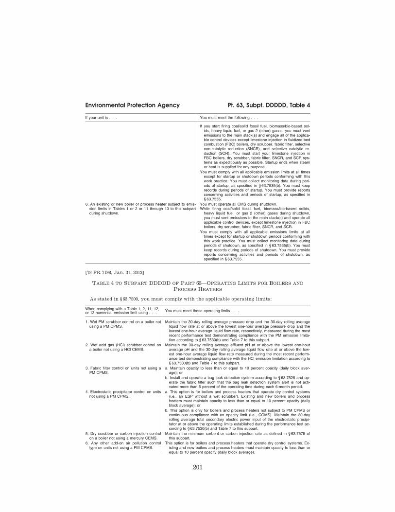
201
Environmental Protection Agency Pt. 63, Subpt. DDDDD, Table 4
If your unit is . . . You must meet the following . . .
If you start firing coal/solid fossil fuel, biomass/bio-based sol-ids, heavy liquid fuel, or gas 2 (other) gases, you must vent emissions to the main stack(s) and engage all of the applica-ble control devices except limestone injection in fluidized bed combustion (FBC) boilers, dry scrubber, fabric filter, selective non-catalytic reduction (SNCR), and selective catalytic re-duction (SCR). You must start your limestone injection in FBC boilers, dry scrubber, fabric filter, SNCR, and SCR sys-tems as expeditiously as possible. Startup ends when steam or heat is supplied for any purpose.
You must comply with all applicable emission limits at all times except for startup or shutdown periods conforming with this work practice. You must collect monitoring data during peri-ods of startup, as specified in § 63.7535(b). You must keep records during periods of startup. You must provide reports concerning activities and periods of startup, as specified in § 63.7555.
6. An existing or new boiler or process heater subject to emis-sion limits in Tables 1 or 2 or 11 through 13 to this subpart during shutdown.
You must operate all CMS during shutdown. While firing coal/solid fossil fuel, biomass/bio-based solids,
heavy liquid fuel, or gas 2 (other) gases during shutdown, you must vent emissions to the main stack(s) and operate all applicable control devices, except limestone injection in FBC boilers, dry scrubber, fabric filter, SNCR, and SCR.
You must comply with all applicable emissions limits at all times except for startup or shutdown periods conforming with this work practice. You must collect monitoring data during periods of shutdown, as specified in § 63.7535(b). You must keep records during periods of shutdown. You must provide reports concerning activities and periods of shutdown, as specified in § 63.7555.
[78 FR 7198, Jan. 31, 2013]
TABLE 4 TO SUBPART DDDDD OF PART 63—OPERATING LIMITS FOR BOILERS AND
PROCESS HEATERS
As stated in § 63.7500, you must comply with the applicable operating limits:
When complying with a Table 1, 2, 11, 12, or 13 numerical emission limit using . . . You must meet these operating limits . . .
1. Wet PM scrubber control on a boiler not using a PM CPMS.
Maintain the 30-day rolling average pressure drop and the 30-day rolling average liquid flow rate at or above the lowest one-hour average pressure drop and the lowest one-hour average liquid flow rate, respectively, measured during the most recent performance test demonstrating compliance with the PM emission limita-tion according to § 63.7530(b) and Table 7 to this subpart.
2. Wet acid gas (HCl) scrubber control on a boiler not using a HCl CEMS.
Maintain the 30-day rolling average effluent pH at or above the lowest one-hour average pH and the 30-day rolling average liquid flow rate at or above the low-est one-hour average liquid flow rate measured during the most recent perform-ance test demonstrating compliance with the HCl emission limitation according to § 63.7530(b) and Table 7 to this subpart.
3. Fabric filter control on units not using a PM CPMS.
a. Maintain opacity to less than or equal to 10 percent opacity (daily block aver-age); or
b. Install and operate a bag leak detection system according to § 63.7525 and op-erate the fabric filter such that the bag leak detection system alert is not acti-vated more than 5 percent of the operating time during each 6-month period.
4. Electrostatic precipitator control on units not using a PM CPMS.
a. This option is for boilers and process heaters that operate dry control systems (i.e., an ESP without a wet scrubber). Existing and new boilers and process heaters must maintain opacity to less than or equal to 10 percent opacity (daily block average); or
b. This option is only for boilers and process heaters not subject to PM CPMS or continuous compliance with an opacity limit (i.e., COMS). Maintain the 30-day rolling average total secondary electric power input of the electrostatic precipi-tator at or above the operating limits established during the performance test ac-cording to § 63.7530(b) and Table 7 to this subpart.
5. Dry scrubber or carbon injection control on a boiler not using a mercury CEMS.
Maintain the minimum sorbent or carbon injection rate as defined in § 63.7575 of this subpart.
6. Any other add-on air pollution control type on units not using a PM CPMS.
This option is for boilers and process heaters that operate dry control systems. Ex-isting and new boilers and process heaters must maintain opacity to less than or equal to 10 percent opacity (daily block average).
VerDate Sep<11>2014 13:42 Oct 28, 2014 Jkt 232162 PO 00000 Frm 00211 Fmt 8010 Sfmt 8002 Y:\SGML\232162.XXX 232162wre
ier-
avile
s on
DS
K5T
PT
VN
1PR
OD
with
CF
R
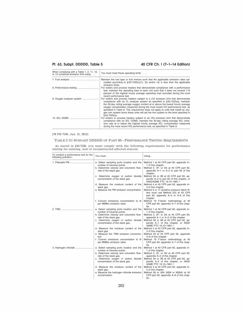
202
40 CFR Ch. I (7–1–14 Edition) Pt. 63, Subpt. DDDDD, Table 5
When complying with a Table 1, 2, 11, 12, or 13 numerical emission limit using . . . You must meet these operating limits . . .
7. Fuel analysis ........................................... Maintain the fuel type or fuel mixture such that the applicable emission rates cal-culated according to § 63.7530(c)(1), (2) and/or (3) is less than the applicable emission limits.
8. Performance testing ................................ For boilers and process heaters that demonstrate compliance with a performance test, maintain the operating load of each unit such that it does not exceed 110 percent of the highest hourly average operating load recorded during the most recent performance test.
9. Oxygen analyzer system ........................ For boilers and process heaters subject to a CO emission limit that demonstrate compliance with an O2 analyzer system as specified in § 63.7525(a), maintain the 30-day rolling average oxygen content at or above the lowest hourly average oxygen concentration measured during the most recent CO performance test, as specified in Table 8. This requirement does not apply to units that install an oxy-gen trim system since these units will set the trim system to the level specified in § 63.7525(a).
10. SO2 CEMS ............................................ For boilers or process heaters subject to an HCl emission limit that demonstrate compliance with an SO2 CEMS, maintain the 30-day rolling average SO2 emis-sion rate at or below the highest hourly average SO2 concentration measured during the most recent HCl performance test, as specified in Table 8.
[78 FR 7199, Jan. 31, 2013]
TABLE 5 TO SUBPART DDDDD OF PART 63—PERFORMANCE TESTING REQUIREMENTS
As stated in § 63.7520, you must comply with the following requirements for performance
testing for existing, new or reconstructed affected sources:
To conduct a performance test for the following pollutant... You must... Using...
1. Filterable PM .................................. a. Select sampling ports location and the number of traverse points.
Method 1 at 40 CFR part 60, appendix A– 1 of this chapter.
b. Determine velocity and volumetric flow- rate of the stack gas.
Method 2, 2F, or 2G at 40 CFR part 60, appendix A–1 or A–2 to part 60 of this chapter.
c. Determine oxygen or carbon dioxide concentration of the stack gas.
Method 3A or 3B at 40 CFR part 60, ap-pendix A–2 to part 60 of this chapter, or ANSI/ASME PTC 19.10–1981.a
d. Measure the moisture content of the stack gas.
Method 4 at 40 CFR part 60, appendix A– 3 of this chapter.
e. Measure the PM emission concentration Method 5 or 17 (positive pressure fabric fil-ters must use Method 5D) at 40 CFR part 60, appendix A–3 or A–6 of this chapter.
f. Convert emissions concentration to lb per MMBtu emission rates.
Method 19 F-factor methodology at 40 CFR part 60, appendix A–7 of this chap-ter.
2. TSM ................................................ a. Select sampling ports location and the number of traverse points.
Method 1 at 40 CFR part 60, appendix A– 1 of this chapter.
b. Determine velocity and volumetric flow- rate of the stack gas.
Method 2, 2F, or 2G at 40 CFR part 60, appendix A–1 or A–2 of this chapter.
c. Determine oxygen or carbon dioxide concentration of the stack gas.
Method 3A or 3B at 40 CFR part 60, ap-pendix A–1 of this chapter, or ANSI/ ASME PTC 19.10–1981.a
d. Measure the moisture content of the stack gas.
Method 4 at 40 CFR part 60, appendix A– 3 of this chapter.
e. Measure the TSM emission concentra-tion.
Method 29 at 40 CFR part 60, appendix A–8 of this chapter
f. Convert emissions concentration to lb per MMBtu emission rates.
Method 19 F-factor methodology at 40 CFR part 60, appendix A–7 of this chap-ter.
3. Hydrogen chloride .......................... a. Select sampling ports location and the number of traverse points.
Method 1 at 40 CFR part 60, appendix A– 1 of this chapter.
b. Determine velocity and volumetric flow- rate of the stack gas.
Method 2, 2F, or 2G at 40 CFR part 60, appendix A–2 of this chapter.
c. Determine oxygen or carbon dioxide concentration of the stack gas.
Method 3A or 3B at 40 CFR part 60, ap-pendix A–2 of this chapter, or ANSI/ ASME PTC 19.10–1981.a
d. Measure the moisture content of the stack gas.
Method 4 at 40 CFR part 60, appendix A– 3 of this chapter.
e. Measure the hydrogen chloride emission concentration.
Method 26 or 26A (M26 or M26A) at 40 CFR part 60, appendix A–8 of this chap-ter.
VerDate Sep<11>2014 13:42 Oct 28, 2014 Jkt 232162 PO 00000 Frm 00212 Fmt 8010 Sfmt 8002 Y:\SGML\232162.XXX 232162wre
ier-
avile
s on
DS
K5T
PT
VN
1PR
OD
with
CF
R
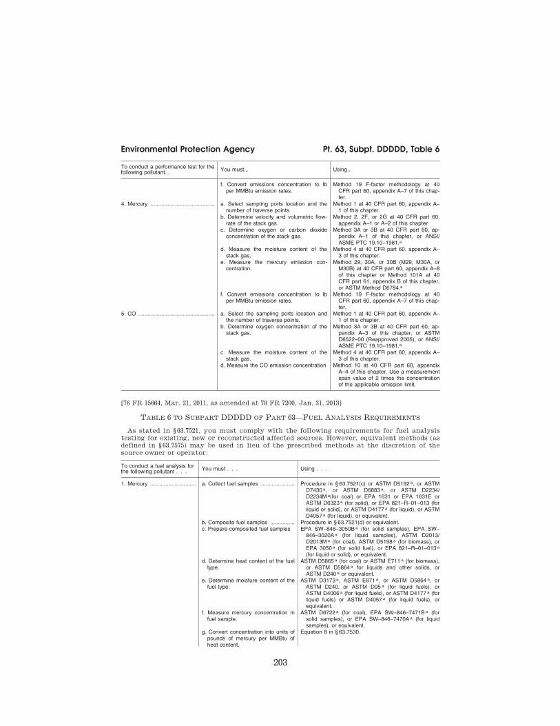
203
Environmental Protection Agency Pt. 63, Subpt. DDDDD, Table 6
To conduct a performance test for the following pollutant... You must... Using...
f. Convert emissions concentration to lb per MMBtu emission rates.
Method 19 F-factor methodology at 40 CFR part 60, appendix A–7 of this chap-ter.
4. Mercury .......................................... a. Select sampling ports location and the number of traverse points.
Method 1 at 40 CFR part 60, appendix A– 1 of this chapter.
b. Determine velocity and volumetric flow- rate of the stack gas.
Method 2, 2F, or 2G at 40 CFR part 60, appendix A–1 or A–2 of this chapter.
c. Determine oxygen or carbon dioxide concentration of the stack gas.
Method 3A or 3B at 40 CFR part 60, ap-pendix A–1 of this chapter, or ANSI/ ASME PTC 19.10–1981.a
d. Measure the moisture content of the stack gas.
Method 4 at 40 CFR part 60, appendix A– 3 of this chapter.
e. Measure the mercury emission con-centration.
Method 29, 30A, or 30B (M29, M30A, or M30B) at 40 CFR part 60, appendix A–8 of this chapter or Method 101A at 40 CFR part 61, appendix B of this chapter, or ASTM Method D6784.a
f. Convert emissions concentration to lb per MMBtu emission rates.
Method 19 F-factor methodology at 40 CFR part 60, appendix A–7 of this chap-ter.
5. CO .................................................. a. Select the sampling ports location and the number of traverse points.
Method 1 at 40 CFR part 60, appendix A– 1 of this chapter.
b. Determine oxygen concentration of the stack gas.
Method 3A or 3B at 40 CFR part 60, ap-pendix A–3 of this chapter, or ASTM D6522–00 (Reapproved 2005), or ANSI/ ASME PTC 19.10–1981.a
c. Measure the moisture content of the stack gas.
Method 4 at 40 CFR part 60, appendix A– 3 of this chapter.
d. Measure the CO emission concentration Method 10 at 40 CFR part 60, appendix A–4 of this chapter. Use a measurement span value of 2 times the concentration of the applicable emission limit.
[76 FR 15664, Mar. 21, 2011, as amended at 78 FR 7200, Jan. 31, 2013]
TABLE 6 TO SUBPART DDDDD OF PART 63—FUEL ANALYSIS REQUIREMENTS
As stated in § 63.7521, you must comply with the following requirements for fuel analysis
testing for existing, new or reconstructed affected sources. However, equivalent methods (as
defined in § 63.7575) may be used in lieu of the prescribed methods at the discretion of the
source owner or operator:
To conduct a fuel analysis for the following pollutant . . . You must . . . Using . . .
1. Mercury .............................. a. Collect fuel samples ...................... Procedure in § 63.7521(c) or ASTM D5192 a, or ASTM D7430 a, or ASTM D6883 a, or ASTM D2234/ D2234M a(for coal) or EPA 1631 or EPA 1631E or ASTM D6323 a (for solid), or EPA 821–R–01–013 (for liquid or solid), or ASTM D4177 a (for liquid), or ASTM D4057 a (for liquid), or equivalent.
b. Composite fuel samples ................ Procedure in § 63.7521(d) or equivalent. c. Prepare composited fuel samples EPA SW–846–3050B a (for solid samples), EPA SW–
846–3020A a (for liquid samples), ASTM D2013/ D2013M a (for coal), ASTM D5198 a (for biomass), or EPA 3050 a (for solid fuel), or EPA 821–R–01–013 a (for liquid or solid), or equivalent.
d. Determine heat content of the fuel type.
ASTM D5865 a (for coal) or ASTM E711 a (for biomass), or ASTM D5864 a for liquids and other solids, or ASTM D240 a or equivalent.
e. Determine moisture content of the fuel type.
ASTM D3173 a, ASTM E871 a, or ASTM D5864 a, or ASTM D240, or ASTM D95 a (for liquid fuels), or ASTM D4006 a (for liquid fuels), or ASTM D4177 a (for liquid fuels) or ASTM D4057 a (for liquid fuels), or equivalent.
f. Measure mercury concentration in fuel sample.
ASTM D6722 a (for coal), EPA SW–846–7471B a (for solid samples), or EPA SW–846–7470A a (for liquid samples), or equivalent.
g. Convert concentration into units of pounds of mercury per MMBtu of heat content.
Equation 8 in § 63.7530.
VerDate Sep<11>2014 13:42 Oct 28, 2014 Jkt 232162 PO 00000 Frm 00213 Fmt 8010 Sfmt 8002 Y:\SGML\232162.XXX 232162wre
ier-
avile
s on
DS
K5T
PT
VN
1PR
OD
with
CF
R

204
40 CFR Ch. I (7–1–14 Edition) Pt. 63, Subpt. DDDDD, Table 6
To conduct a fuel analysis for the following pollutant . . . You must . . . Using . . .
h. Calculate the mercury emission rate from the boiler or process heater in units of pounds per mil-lion Btu.
Equations 10 and 12 in § 63.7530.
2. HCl ..................................... a. Collect fuel samples ...................... Procedure in § 63.7521(c) or ASTM D5192 a, or ASTM D7430 a, or ASTM D6883 a, or ASTM D2234/ D2234M a (for coal) or ASTM D6323 a (for coal or bio-mass), ASTM D4177 a (for liquid fuels) or ASTM D4057 a (for liquid fuels), or equivalent.
b. Composite fuel samples ................ Procedure in § 63.7521(d) or equivalent. c. Prepare composited fuel samples EPA SW–846–3050B a (for solid samples), EPA SW–
846–3020A a (for liquid samples), ASTM D2013/ D2013M§a (for coal), or ASTM D5198§a (for bio-mass), or EPA 3050 a or equivalent.
d. Determine heat content of the fuel type.
ASTM D5865 a (for coal) or ASTM E711 a (for biomass), ASTM D5864, ASTM D240 a or equivalent.
e. Determine moisture content of the fuel type.
ASTM D3173 a or ASTM E871 a, or D5864 a, or ASTM D240 a, or ASTM D95a (for liquid fuels), or ASTM D4006 a (for liquid fuels), or ASTM D4177 a (for liquid fuels) or ASTM D4057 a (for liquid fuels) or equivalent.
f. Measure chlorine concentration in fuel sample.
EPA SW–846–9250 a, ASTM D6721 a, ASTM D4208 a (for coal), or EPA SW–846–5050 a or ASTM E776 a (for solid fuel), or EPA SW–846–9056 a or SW–846– 9076 a (for solids or liquids) or equivalent.
g. Convert concentrations into units of pounds of HCl per MMBtu of heat content.
Equation 7 in § 63.7530.
h. Calculate the HCl emission rate from the boiler or process heater in units of pounds per million Btu.
Equations 10 and 11 in § 63.7530.
3. Mercury Fuel Specification for other gas 1 fuels.
a. Measure mercury concentration in the fuel sample and convert to units of micrograms per cubic meter.
Method 30B (M30B) at 40 CFR part 60, appendix A–8 of this chapter or ASTM D5954 a, ASTM D6350 a, ISO 6978–1:2003(E) a, or ISO 6978–2:2003(E) a, or EPA– 1631 a or equivalent.
b. Measure mercury concentration in the exhaust gas when firing only the other gas 1 fuel is fired in the boiler or process heater.
Method 29, 30A, or 30B (M29, M30A, or M30B) at 40 CFR part 60, appendix A–8 of this chapter or Method 101A or Method 102 at 40 CFR part 61, appendix B of this chapter, or ASTM Method D6784 a or equiva-lent.
4. TSM for solid fuels ............. a. Collect fuel samples ...................... Procedure in § 63.7521(c) or ASTM D5192 a, or ASTM D7430 a, or ASTM D6883 a, or ASTM D2234/ D2234M a (for coal) or ASTM D6323 a (for coal or bio-mass), or ASTM D4177 a,(for liquid fuels)or ASTM D4057 a (for liquid fuels),or equivalent.
b. Composite fuel samples ................ Procedure in § 63.7521(d) or equivalent. c. Prepare composited fuel samples EPA SW–846–3050B a (for solid samples), EPA SW–
846–3020A a (for liquid samples), ASTM D2013/ D2013M a (for coal), ASTM D5198 a or TAPPI T266 a (for biomass), or EPA 3050 a or equivalent.
d. Determine heat content of the fuel type.
ASTM D5865 a (for coal) or ASTM E711 a (for biomass), or ASTM D5864 a for liquids and other solids, or ASTM D240 a or equivalent.
e. Determine moisture content of the fuel type.
ASTM D3173 a or ASTM E871 a, or D5864, or ASTM D240 a, or ASTM D95 a (for liquid fuels), or ASTM D4006a (for liquid fuels), or ASTM D4177 a (for liquid fuels) or ASTM D4057 a (for liquid fuels), or equiva-lent.
f. Measure TSM concentration in fuel sample.
ASTM D3683 a, or ASTM D4606 a, or ASTM D6357 a or EPA 200.8 a or EPA SW–846–6020 a, or EPA SW– 846–6020A a, or EPA SW–846–6010C a, EPA 7060 a or EPA 7060A a (for arsenic only), or EPA SW–846– 7740 a (for selenium only).
g. Convert concentrations into units of pounds of TSM per MMBtu of heat content.
Equation 9 in § 63.7530.
h. Calculate the TSM emission rate from the boiler or process heater in units of pounds per million Btu.
Equations 10 and 13 in § 63.7530.
a Incorporated by reference, see § 63.14.
[78 FR 7201, Jan. 31, 2013]
VerDate Sep<11>2014 13:42 Oct 28, 2014 Jkt 232162 PO 00000 Frm 00214 Fmt 8010 Sfmt 8026 Y:\SGML\232162.XXX 232162wre
ier-
avile
s on
DS
K5T
PT
VN
1PR
OD
with
CF
R

205
Environmental Protection Agency Pt. 63, Subpt. DDDDD, Table 7
TABLE 7 TO SUBPART DDDDD OF PART 63—ESTABLISHING OPERATING LIMITS
As stated in § 63.7520, you must comply with the following requirements for establishing op-
erating limits:
If you have an applica-ble emission limit for . . .
And your operating lim-its are based on . . . You must . . . Using . . . According to the fol-
lowing requirements
1. PM, TSM, or mer-cury.
a. Wet scrubber oper-ating parameters.
i. Establish a site-spe-cific minimum scrub-ber pressure drop and minimum flow rate operating limit according to § 63.7530(b).
(1) Data from the scrubber pressure drop and liquid flow rate monitors and the PM or mercury per-formance test.
(a) You must collect scrubber pressure drop and liquid flow rate data every 15 minutes during the entire period of the performance tests.
(b) Determine the low-est hourly average scrubber pressure drop and liquid flow rate by computing the hourly averages using all of the 15- minute readings taken during each performance test.
b. Electrostatic precipi-tator operating pa-rameters (option only for units that operate wet scrubbers).
i. Establish a site-spe-cific minimum total secondary electric power input accord-ing to § 63.7530(b).
(1) Data from the volt-age and secondary amperage monitors during the PM or mercury performance test.
(a) You must collect secondary voltage and secondary am-perage for each ESP cell and calculate total secondary elec-tric power input data every 15 minutes during the entire pe-riod of the perform-ance tests.
(b) Determine the aver-age total secondary electric power input by computing the hourly averages using all of the 15- minute readings taken during each performance test.
2. HCl ........................... a. Wet scrubber oper-ating parameters.
i. Establish site-specific minimum pressure drop, effluent pH, and flow rate oper-ating limits according to § 63.7530(b).
(1) Data from the pres-sure drop, pH, and liquid flow-rate mon-itors and the HCl per-formance test.
(a) You must collect pH and liquid flow-rate data every 15 min-utes during the entire period of the per-formance tests.
(b) Determine the hour-ly average pH and liquid flow rate by computing the hourly averages using all of the 15-minute read-ings taken during each performance test.
b. Dry scrubber oper-ating parameters.
i. Establish a site-spe-cific minimum sor-bent injection rate operating limit ac-cording to § 63.7530(b). If dif-ferent acid gas sorbents are used during the HCl per-formance test, the average value for each sorbent be-comes the site-spe-cific operating limit for that sorbent.
(1) Data from the sor-bent injection rate monitors and HCl or mercury performance test.
(a) You must collect sorbent injection rate data every 15 min-utes during the entire period of the per-formance tests.
VerDate Sep<11>2014 13:42 Oct 28, 2014 Jkt 232162 PO 00000 Frm 00215 Fmt 8010 Sfmt 8002 Y:\SGML\232162.XXX 232162wre
ier-
avile
s on
DS
K5T
PT
VN
1PR
OD
with
CF
R

206
40 CFR Ch. I (7–1–14 Edition) Pt. 63, Subpt. DDDDD, Table 7
If you have an applica-ble emission limit for . . .
And your operating lim-its are based on . . . You must . . . Using . . . According to the fol-
lowing requirements
(b) Determine the hour-ly average sorbent injection rate by com-puting the hourly averages using all of the 15-minute read-ings taken during each performance test.
(c) Determine the low-est hourly average of the three test run averages established during the perform-ance test as your op-erating limit. When your unit operates at lower loads, multiply your sorbent injection rate by the load frac-tion (e.g., for 50 per-cent load, multiply the injection rate op-erating limit by 0.5) to determine the re-quired injection rate.
c. Alternative Maximum SO2 emission rate.
i. Establish a site-spe-cific maximum SO2 emission rate oper-ating limit according to § 63.7530(b).
(1) Data from SO2 CEMS and the HCl performance test.
(a) You must collect the SO2 emissions data according to § 63.7525(m) during the most recent HCl performance tests.
(b) The maximum SO2 emission rate is equal to the lowest hourly average SO2 emission rate meas-ured during the most recent HCl perform-ance tests.
3. Mercury .................... a. Activated carbon in-jection.
i. Establish a site-spe-cific minimum acti-vated carbon injec-tion rate operating limit according to § 63.7530(b).
(1) Data from the acti-vated carbon rate monitors and mer-cury performance test.
(a) You must collect ac-tivated carbon injec-tion rate data every 15 minutes during the entire period of the performance tests.
(b) Determine the hour-ly average activated carbon injection rate by computing the hourly averages using all of the 15- minute readings taken during each performance test.
VerDate Sep<11>2014 13:42 Oct 28, 2014 Jkt 232162 PO 00000 Frm 00216 Fmt 8010 Sfmt 8002 Y:\SGML\232162.XXX 232162wre
ier-
avile
s on
DS
K5T
PT
VN
1PR
OD
with
CF
R

207
Environmental Protection Agency Pt. 63, Subpt. DDDDD, Table 7
If you have an applica-ble emission limit for . . .
And your operating lim-its are based on . . . You must . . . Using . . . According to the fol-
lowing requirements
(c) Determine the low-est hourly average established during the performance test as your operating limit. When your unit operates at lower loads, multiply your activated carbon in-jection rate by the load fraction (e.g., actual heat input di-vided by heat input during performance test, for 50 percent load, multiply the in-jection rate operating limit by 0.5) to deter-mine the required in-jection rate.
4. Carbon monoxide .... a. Oxygen .................... i. Establish a unit-spe-cific limit for minimum oxygen level accord-ing to § 63.7520.
(1) Data from the oxy-gen analyzer system specified in § 63.7525(a).
(a) You must collect ox-ygen data every 15 minutes during the entire period of the performance tests.
(b) Determine the hour-ly average oxygen concentration by computing the hourly averages using all of the 15-minute read-ings taken during each performance test.
(c) Determine the low-est hourly average established during the performance test as your minimum op-erating limit.
5. Any pollutant for which compliance is demonstrated by a performance test.
a. Boiler or process heater operating load.
i. Establish a unit spe-cific limit for max-imum operating load according to § 63.7520(c).
(1) Data from the oper-ating load monitors or from steam gen-eration monitors.
(a) You must collect operating load or steam generation data every 15 min-utes during the entire period of the per-formance test.
(b) Determine the aver-age operating load by computing the hourly averages using all of the 15- minute readings taken during each performance test.
(c) Determine the aver-age of the three test run averages during the performance test, and multiply this by 1.1 (110 percent) as your operating limit.
[76 FR 15664, Mar. 21, 2011, as amended at 78 FR 7203, Jan. 31, 2013]
VerDate Sep<11>2014 13:42 Oct 28, 2014 Jkt 232162 PO 00000 Frm 00217 Fmt 8010 Sfmt 8026 Y:\SGML\232162.XXX 232162wre
ier-
avile
s on
DS
K5T
PT
VN
1PR
OD
with
CF
R

208
40 CFR Ch. I (7–1–14 Edition) Pt. 63, Subpt. DDDDD, Table 8
TABLE 8 TO SUBPART DDDDD OF PART 63—DEMONSTRATING CONTINUOUS
COMPLIANCE
As stated in § 63.7540, you must show continuous compliance with the emission limitations
for each boiler or process heater according to the following:
If you must meet the following operating limits or work practice standards . . . You must demonstrate continuous compliance by . . .
1. Opacity .................................................... a. Collecting the opacity monitoring system data according to § 63.7525(c) and § 63.7535; and
b. Reducing the opacity monitoring data to 6-minute averages; and c. Maintaining opacity to less than or equal to 10 percent (daily block average).
2. PM CPMS ............................................... a. Collecting the PM CPMS output data according to § 63.7525; b. Reducing the data to 30-day rolling averages; and c. Maintaining the 30-day rolling average PM CPMS output data to less than the
operating limit established during the performance test according to § 63.7530(b)(4).
3. Fabric Filter Bag Leak Detection Oper-ation.
Installing and operating a bag leak detection system according to § 63.7525 and operating the fabric filter such that the requirements in § 63.7540(a)(9) are met.
4. Wet Scrubber Pressure Drop and Liquid Flow-rate.
a. Collecting the pressure drop and liquid flow rate monitoring system data accord-ing to §§ 63.7525 and 63.7535; and
b. Reducing the data to 30-day rolling averages; and c. Maintaining the 30-day rolling average pressure drop and liquid flow-rate at or
above the operating limits established during the performance test according to § 63.7530(b).
5. Wet Scrubber pH .................................... a. Collecting the pH monitoring system data according to §§ 63.7525 and 63.7535; and
b. Reducing the data to 30-day rolling averages; and c. Maintaining the 30-day rolling average pH at or above the operating limit estab-
lished during the performance test according to § 63.7530(b). 6. Dry Scrubber Sorbent or Carbon Injec-
tion Rate.a. Collecting the sorbent or carbon injection rate monitoring system data for the dry
scrubber according to §§ 63.7525 and 63.7535; and b. Reducing the data to 30-day rolling averages; and c. Maintaining the 30-day rolling average sorbent or carbon injection rate at or
above the minimum sorbent or carbon injection rate as defined in § 63.7575. 7. Electrostatic Precipitator Total Sec-
ondary Electric Power Input.a. Collecting the total secondary electric power input monitoring system data for
the electrostatic precipitator according to §§ 63.7525 and 63.7535; and b. Reducing the data to 30-day rolling averages; and c. Maintaining the 30-day rolling average total secondary electric power input at or
above the operating limits established during the performance test according to § 63.7530(b).
8. Emission limits using fuel analysis ......... a. Conduct monthly fuel analysis for HCl or mercury or TSM according to Table 6 to this subpart; and
b. Reduce the data to 12-month rolling averages; and c. Maintain the 12-month rolling average at or below the applicable emission limit
for HCl or mercury or TSM in Tables 1 and 2 or 11 through 13 to this subpart. 9. Oxygen content ....................................... a. Continuously monitor the oxygen content using an oxygen analyzer system ac-
cording to § 63.7525(a). This requirement does not apply to units that install an oxygen trim system since these units will set the trim system to the level speci-fied in § 63.7525(a)(2).
b. Reducing the data to 30-day rolling averages; and c. Maintain the 30-day rolling average oxygen content at or above the lowest hour-
ly average oxygen level measured during the most recent CO performance test. 10. Boiler or process heater operating load a. Collecting operating load data or steam generation data every 15 minutes.
b. Maintaining the operating load such that it does not exceed 110 percent of the highest hourly average operating load recorded during the most recent perform-ance test according to § 63.7520(c).
11. SO2 emissions using SO2 CEMS ......... a. Collecting the SO2 CEMS output data according to § 63.7525; b. Reducing the data to 30-day rolling averages; and c. Maintaining the 30-day rolling average SO2 CEMS emission rate to a level at or
below the minimum hourly SO2 rate measured during the most recent HCl per-formance test according to § 63.7530.
[78 FR 7204, Jan. 31, 2013]
VerDate Sep<11>2014 13:42 Oct 28, 2014 Jkt 232162 PO 00000 Frm 00218 Fmt 8010 Sfmt 8026 Y:\SGML\232162.XXX 232162wre
ier-
avile
s on
DS
K5T
PT
VN
1PR
OD
with
CF
R

209
Environmental Protection Agency Pt. 63, Subpt. DDDDD, Table 10
TABLE 9 TO SUBPART DDDDD OF PART 63—REPORTING REQUIREMENTS
As stated in § 63.7550, you must comply with the following requirements for reports:
You must submit a(n) The report must contain . . . You must submit the re-port . . .
1. Compliance report ....... a. Information required in § 63.7550(c)(1) through (5); and Semiannually, annually, biennially, or every 5 years according to the requirements in § 63.7550(b).
b. If there are no deviations from any emission limitation (emission limit and operating limit) that applies to you and there are no deviations from the requirements for work practice standards in Table 3 to this subpart that apply to you, a statement that there were no deviations from the emission limitations and work practice standards during the reporting period. If there were no periods during which the CMSs, in-cluding continuous emissions monitoring system, continuous opacity monitoring system, and operating parameter monitoring systems, were out-of-control as specified in § 63.8(c)(7), a statement that there were no periods during which the CMSs were out-of-control during the re-porting period; and
c. If you have a deviation from any emission limitation (emission limit and operating limit) where you are not using a CMS to comply with that emission limit or operating limit, or a deviation from a work practice standard during the reporting period, the report must contain the infor-mation in § 63.7550(d); and
d. If there were periods during which the CMSs, including continuous emissions monitoring system, continuous opacity monitoring system, and operating parameter monitoring systems, were out-of-control as specified in § 63.8(c)(7), or otherwise not operating, the report must contain the information in § 63.7550(e).
[76 FR 15664, Mar. 21, 2011, as amended at 78 FR 7205, Jan. 31, 2013]
TABLE 10 TO SUBPART DDDDD OF PART 63—APPLICABILITY OF GENERAL PROVISIONS
TO SUBPART DDDDD
As stated in § 63.7565, you must comply with the applicable General Provisions according
to the following:
Citation Subject Applies to subpart DDDDD
§ 63.1 ........................................ Applicability ............................................................................... Yes. § 63.2 ........................................ Definitions ................................................................................. Yes. Additional terms defined
in § 63.7575 § 63.3 ........................................ Units and Abbreviations ............................................................ Yes. § 63.4 ........................................ Prohibited Activities and Circumvention ................................... Yes. § 63.5 ........................................ Preconstruction Review and Notification Requirements .......... Yes. § 63.6(a), (b)(1)–(b)(5), (b)(7),
(c).Compliance with Standards and Maintenance Requirements Yes.
§ 63.6(e)(1)(i) ............................ General duty to minimize emissions. ........................................ No. See § 63.7500(a)(3) for the general duty require-ment.
§ 63.6(e)(1)(ii) ........................... Requirement to correct malfunctions as soon as practicable. No. § 63.6(e)(3) ............................... Startup, shutdown, and malfunction plan requirements. .......... No. § 63.6(f)(1) ................................ Startup, shutdown, and malfunction exemptions for compli-
ance with non-opacity emission standards..No.
§ 63.6(f)(2) and (3) ................... Compliance with non-opacity emission standards. .................. Yes. § 63.6(g) ................................... Use of alternative standards ..................................................... Yes. § 63.6(h)(1) ............................... Startup, shutdown, and malfunction exemptions to opacity
standards..No. See § 63.7500(a).
§ 63.6(h)(2) to (h)(9) ................. Determining compliance with opacity emission standards ....... Yes. § 63.6(i) ..................................... Extension of compliance ........................................................... Yes. Note: Facilities may also
request extensions of com-pliance for the installation of combined heat and power, waste heat recovery, or gas pipeline or fuel feeding infra-structure as a means of complying with this subpart.
§ 63.6(j) ..................................... Presidential exemption. ............................................................. Yes. § 63.7(a), (b), (c), and (d) ......... Performance Testing Requirements ......................................... Yes.
VerDate Sep<11>2014 13:42 Oct 28, 2014 Jkt 232162 PO 00000 Frm 00219 Fmt 8010 Sfmt 8002 Y:\SGML\232162.XXX 232162wre
ier-
avile
s on
DS
K5T
PT
VN
1PR
OD
with
CF
R
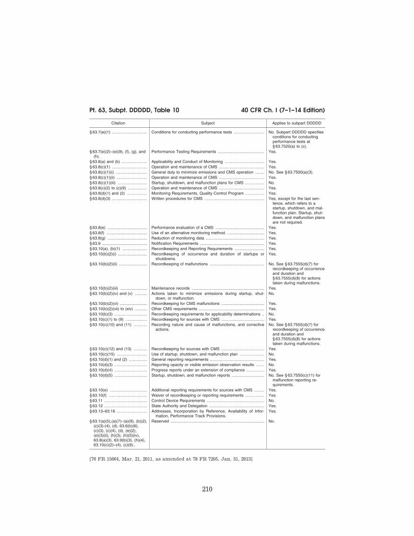
210
40 CFR Ch. I (7–1–14 Edition) Pt. 63, Subpt. DDDDD, Table 10
Citation Subject Applies to subpart DDDDD
§ 63.7(e)(1) ............................... Conditions for conducting performance tests ........................... No. Subpart DDDDD specifies conditions for conducting performance tests at § 63.7520(a) to (c).
§ 63.7(e)(2)–(e)(9), (f), (g), and (h).
Performance Testing Requirements ......................................... Yes.
§ 63.8(a) and (b) ....................... Applicability and Conduct of Monitoring ................................... Yes. § 63.8(c)(1) ............................... Operation and maintenance of CMS ........................................ Yes. § 63.8(c)(1)(i) ............................ General duty to minimize emissions and CMS operation ........ No. See § 63.7500(a)(3). § 63.8(c)(1)(ii) ........................... Operation and maintenance of CMS ........................................ Yes. § 63.8(c)(1)(iii) .......................... Startup, shutdown, and malfunction plans for CMS ................. No. § 63.8(c)(2) to (c)(9) ................. Operation and maintenance of CMS ........................................ Yes. § 63.8(d)(1) and (2) .................. Monitoring Requirements, Quality Control Program ................. Yes. § 63.8(d)(3) ............................... Written procedures for CMS ..................................................... Yes, except for the last sen-
tence, which refers to a startup, shutdown, and mal-function plan. Startup, shut-down, and malfunction plans are not required.
§ 63.8(e) ................................... Performance evaluation of a CMS ........................................... Yes. § 63.8(f) .................................... Use of an alternative monitoring method. ................................ Yes. § 63.8(g) ................................... Reduction of monitoring data .................................................... Yes. § 63.9 ........................................ Notification Requirements ......................................................... Yes. § 63.10(a), (b)(1) ...................... Recordkeeping and Reporting Requirements .......................... Yes. § 63.10(b)(2)(i) .......................... Recordkeeping of occurrence and duration of startups or
shutdowns.Yes.
§ 63.10(b)(2)(ii) ......................... Recordkeeping of malfunctions ................................................ No. See § 63.7555(d)(7) for recordkeeping of occurrence and duration and § 63.7555(d)(8) for actions taken during malfunctions.
§ 63.10(b)(2)(iii) ........................ Maintenance records ................................................................ Yes. § 63.10(b)(2)(iv) and (v) ........... Actions taken to minimize emissions during startup, shut-
down, or malfunction.No.
§ 63.10(b)(2)(vi) ........................ Recordkeeping for CMS malfunctions ...................................... Yes. § 63.10(b)(2)(vii) to (xiv) ........... Other CMS requirements .......................................................... Yes. § 63.10(b)(3) ............................. Recordkeeping requirements for applicability determinations .. No. § 63.10(c)(1) to (9) ................... Recordkeeping for sources with CMS ...................................... Yes. § 63.10(c)(10) and (11) ............ Recording nature and cause of malfunctions, and corrective
actions.No. See § 63.7555(d)(7) for
recordkeeping of occurrence and duration and § 63.7555(d)(8) for actions taken during malfunctions.
§ 63.10(c)(12) and (13) ............ Recordkeeping for sources with CMS ...................................... Yes. § 63.10(c)(15) ........................... Use of startup, shutdown, and malfunction plan ...................... No. § 63.10(d)(1) and (2) ................ General reporting requirements ................................................ Yes. § 63.10(d)(3) ............................. Reporting opacity or visible emission observation results ....... No. § 63.10(d)(4) ............................. Progress reports under an extension of compliance ................ Yes. § 63.10(d)(5) ............................. Startup, shutdown, and malfunction reports ............................. No. See § 63.7550(c)(11) for
malfunction reporting re-quirements.
§ 63.10(e) ................................. Additional reporting requirements for sources with CMS ......... Yes. § 63.10(f) .................................. Waiver of recordkeeping or reporting requirements ................. Yes. § 63.11 ...................................... Control Device Requirements ................................................... No. § 63.12 ...................................... State Authority and Delegation ................................................. Yes. § 63.13–63.16 ........................... Addresses, Incorporation by Reference, Availability of Infor-
mation, Performance Track Provisions.Yes.
§ 63.1(a)(5),(a)(7)–(a)(9), (b)(2), (c)(3)-(4), (d), 63.6(b)(6), (c)(3), (c)(4), (d), (e)(2), (e)(3)(ii), (h)(3), (h)(5)(iv), 63.8(a)(3), 63.9(b)(3), (h)(4), 63.10(c)(2)–(4), (c)(9)..
Reserved ................................................................................... No.
[76 FR 15664, Mar. 21, 2011, as amended at 78 FR 7205, Jan. 31, 2013]
VerDate Sep<11>2014 13:42 Oct 28, 2014 Jkt 232162 PO 00000 Frm 00220 Fmt 8010 Sfmt 8026 Y:\SGML\232162.XXX 232162wre
ier-
avile
s on
DS
K5T
PT
VN
1PR
OD
with
CF
R

211
Environmental Protection Agency Pt. 63, Subpt. DDDDD, Table 12
TABLE 11 TO SUBPART DDDDD OF PART 63—TOXIC EQUIVALENCY FACTORS FOR
DIOXINS/FURANS
TABLE 11 TO SUBPART DDDDD OF PART 63—TOXIC EQUIVALENCY FACTORS FOR DIOXINS/FURANS
Dioxin/furan congener Toxic equivalency factor
2,3,7,8-tetrachlorinated dibenzo-p-dioxin .................................................................................................... 1 1,2,3,7,8-pentachlorinated dibenzo-p-dioxin ............................................................................................... 1 1,2,3,4,7,8-hexachlorinated dibenzo-p-dioxin ............................................................................................. 0 .1 1,2,3,7,8,9-hexachlorinated dibenzo-p-dioxin ............................................................................................. 0 .1 1,2,3,6,7,8-hexachlorinated dibenzo-p-dioxin ............................................................................................. 0 .1 1,2,3,4,6,7,8-heptachlorinated dibenzo-p-dioxin ......................................................................................... 0 .01 octachlorinated dibenzo-p-dioxin ................................................................................................................. 0 .0003 2,3,7,8-tetrachlorinated dibenzofuran .......................................................................................................... 0 .1 2,3,4,7,8-pentachlorinated dibenzofuran ..................................................................................................... 0 .3 1,2,3,7,8-pentachlorinated dibenzofuran ..................................................................................................... 0 .03 1,2,3,4,7,8-hexachlorinated dibenzofuran ................................................................................................... 0 .1 1,2,3,6,7,8-hexachlorinated dibenzofuran ................................................................................................... 0 .1 1,2,3,7,8,9-hexachlorinated dibenzofuran ................................................................................................... 0 .1 2,3,4,6,7,8-hexachlorinated dibenzofuran ................................................................................................... 0 .1 1,2,3,4,6,7,8-heptachlorinated dibenzofuran ............................................................................................... 0 .01 1,2,3,4,7,8,9-heptachlorinated dibenzofuran ............................................................................................... 0 .01 octachlorinated dibenzofuran ...................................................................................................................... 0 .0003
[76 FR 15664, Mar. 21, 2011]
EDITORIAL NOTE: At 78 FR 7206, Jan. 31, 2013, Table 11 was added, effective Apr. 1, 2013. How-
ever Table 11 could not be added as a Table 11 is already in existence.
TABLE 12 TO SUBPART DDDDD OF PART 63—ALTERNATIVE EMISSION LIMITS FOR NEW
OR RECONSTRUCTED BOILERS AND PROCESS HEATERS THAT COMMENCED CON-
STRUCTION OR RECONSTRUCTION AFTER JUNE 4, 2010, AND BEFORE MAY 20,
2011
If your boiler or process heater is in this sub-category
For the following pollut-ants
The emissions must not exceed the following emission limits, except during periods of start-up and shutdown
Using this specified sampling volume or test run duration
1. Units in all subcategories designed to burn solid fuel.
a. Mercury .................... 3.5E–06 lb per MMBtu of heat input.
For M29, collect a min-imum of 2 dscm per run; for M30A or M30B, collect a min-imum sample as specified in the meth-od; for ASTM D6784 a collect a minimum of 2 dscm.
2. Units in all subcategories designed to burn solid fuel that combust at least 10 percent bio-mass/bio-based solids on an annual heat input basis and less than 10 percent coal/solid fossil fuels on an annual heat input basis.
a. Particulate Matter ..... 0.008 lb per MMBtu of heat input (30-day rolling average for units 250 MMBtu/hr or greater, 3-run av-erage for units less than 250 MMBtu/hr).
Collect a minimum of 1 dscm per run.
b. Hydrogen Chloride ... 0.004 lb per MMBtu of heat input.
For M26A, collect a minimum of 1 dscm per run; for M26, col-lect a minimum of 60 liters per run.
3. Units in all subcategories designed to burn solid fuel that combust at least 10 percent coal/solid fossil fuels on an annual heat input basis and less than 10 percent biomass/bio- based solids on an annual heat input basis.
a. Particulate Matter ..... 0.0011 lb per MMBtu of heat input (30-day rolling average for units 250 MMBtu/hr or greater, 3-run av-erage for units less than 250 MMBtu/hr).
Collect a minimum of 3 dscm per run.
VerDate Sep<11>2014 13:42 Oct 28, 2014 Jkt 232162 PO 00000 Frm 00221 Fmt 8010 Sfmt 8002 Y:\SGML\232162.XXX 232162wre
ier-
avile
s on
DS
K5T
PT
VN
1PR
OD
with
CF
R

212
40 CFR Ch. I (7–1–14 Edition) Pt. 63, Subpt. DDDDD, Table 12
If your boiler or process heater is in this sub-category
For the following pollut-ants
The emissions must not exceed the following emission limits, except during periods of start-up and shutdown
Using this specified sampling volume or test run duration
b. Hydrogen Chloride ... 0.0022 lb per MMBtu of heat input.
For M26A, collect a minimum of 1 dscm per run; for M26, col-lect a minimum of 60 liters per run.
4. Units designed to burn pulverized coal/solid fossil fuel.
a. CO ............................ 90 ppm by volume on a dry basis corrected to 3 percent oxygen.
1 hr minimum sampling time.
b. Dioxins/Furans ......... 0.003 ng/dscm (TEQ) corrected to 7 percent oxygen.
Collect a minimum of 4 dscm per run.
5. Stokers designed to burn coal/solid fossil fuel a. CO ............................ 7 ppm by volume on a dry basis corrected to 3 percent oxygen.
1 hr minimum sampling time.
b. Dioxins/Furans ......... 0.003 ng/dscm (TEQ) corrected to 7 percent oxygen.
Collect a minimum of 4 dscm per run.
6. Fluidized bed units designed to burn coal/solid fossil fuel.
a. CO ............................ 30 ppm by volume on a dry basis corrected to 3 percent oxygen.
1 hr minimum sampling time.
b. Dioxins/Furans ......... 0.002 ng/dscm (TEQ) corrected to 7 percent oxygen.
Collect a minimum of 4 dscm per run.
7. Stokers designed to burn biomass/bio-based solids.
a. CO ............................ 560 ppm by volume on a dry basis corrected to 3 percent oxygen.
1 hr minimum sampling time.
b. Dioxins/Furans ......... 0.005 ng/dscm (TEQ) corrected to 7 percent oxygen.
Collect a minimum of 4 dscm per run.
8. Fluidized bed units designed to burn biomass/ bio-based solids.
a. CO ............................ 260 ppm by volume on a dry basis corrected to 3 percent oxygen.
1 hr minimum sampling time.
b. Dioxins/Furans ......... 0.02 ng/dscm (TEQ) corrected to 7 percent oxygen.
Collect a minimum of 4 dscm per run.
9. Suspension burners/Dutch Ovens designed to burn biomass/bio-based solids.
a. CO ............................ 1,010 ppm by volume on a dry basis cor-rected to 3 percent oxygen.
1 hr minimum sampling time.
b. Dioxins/Furans ......... 0.2 ng/dscm (TEQ) cor-rected to 7 percent oxygen.
Collect a minimum of 4 dscm per run.
10. Fuel cells designed to burn biomass/bio- based solids.
a. CO ............................ 470 ppm by volume on a dry basis corrected to 3 percent oxygen.
1 hr minimum sampling time.
b. Dioxins/Furans ......... 0.003 ng/dscm (TEQ) corrected to 7 percent oxygen.
Collect a minimum of 4 dscm per run.
11. Hybrid suspension/grate units designed to burn biomass/bio-based solids.
a. CO ............................ 1,500 ppm by volume on a dry basis cor-rected to 3 percent oxygen.
1 hr minimum sampling time.
b. Dioxins/Furans ......... 0.2 ng/dscm (TEQ) cor-rected to 7 percent oxygen.
Collect a minimum of 4 dscm per run.
12. Units designed to burn liquid fuel .................. a. Particulate Matter ..... 0.002 lb per MMBtu of heat input (30-day rolling average for units 250 MMBtu/hr or greater, 3-run av-erage for units less than 250 MMBtu/hr).
Collect a minimum of 2 dscm per run.
b. Hydrogen Chloride ... 0.0032 lb per MMBtu of heat input.
For M26A, collect a minimum of 1 dscm per run; for M26, col-lect a minimum of 60 liters per run.
VerDate Sep<11>2014 13:42 Oct 28, 2014 Jkt 232162 PO 00000 Frm 00222 Fmt 8010 Sfmt 8002 Y:\SGML\232162.XXX 232162wre
ier-
avile
s on
DS
K5T
PT
VN
1PR
OD
with
CF
R

213
Environmental Protection Agency Pt. 63, Subpt. DDDDD, Table 12
If your boiler or process heater is in this sub-category
For the following pollut-ants
The emissions must not exceed the following emission limits, except during periods of start-up and shutdown
Using this specified sampling volume or test run duration
c. Mercury ..................... 3.0E–07 lb per MMBtu of heat input.
For M29, collect a min-imum of 2 dscm per run; for M30A or M30B, collect a min-imum sample as specified in the meth-od; for ASTM D6784 a collect a minimum of 2 dscm.
d. CO ............................ 3 ppm by volume on a dry basis corrected to 3 percent oxygen.
1 hr minimum sampling time.
e. Dioxins/Furans ......... 0.002 ng/dscm (TEQ) corrected to 7 percent oxygen.
Collect a minimum of 4 dscm per run.
13. Units designed to burn liquid fuel located in non-continental States and territories.
a. Particulate Matter ..... 0.002 lb per MMBtu of heat input (30-day rolling average for units 250 MMBtu/hr or greater, 3-run av-erage for units less than 250 MMBtu/hr).
Collect a minimum of 2 dscm per run.
b. Hydrogen Chloride ... 0.0032 lb per MMBtu of heat input.
For M26A, collect a minimum of 1 dscm per run; for M26, col-lect a minimum of 60 liters per run.
c. Mercury ..................... 7.8E–07 lb per MMBtu of heat input.
For M29, collect a min-imum of 1 dscm per run; for M30A or M30B, collect a min-imum sample as specified in the meth-od; for ASTM D6784 a collect a minimum of 2 dscm.
d. CO ............................ 51 ppm by volume on a dry basis corrected to 3 percent oxygen.
1 hr minimum sampling time.
e. Dioxins/Furans ......... 0.002 ng/dscm (TEQ) corrected to 7 percent oxygen.
Collect a minimum of 4 dscm per run.
14. Units designed to burn gas 2 (other) gases .. a. Particulate Matter ..... 0.0067 lb per MMBtu of heat input (30-day rolling average for units 250 MMBtu/hr or greater, 3-run av-erage for units less than 250 MMBtu/hr).
Collect a minimum of 1 dscm per run.
b. Hydrogen Chloride ... 0.0017 lb per MMBtu of heat input.
For M26A, collect a minimum of 1 dscm per run; for M26, col-lect a minimum of 60 liters per run.
c. Mercury ..................... 7.9E–06 lb per MMBtu of heat input.
For M29, collect a min-imum of 1 dscm per run; for M30A or M30B, collect a min-imum sample as specified in the meth-od; for ASTM D6784 a collect a minimum of 2 dscm.
d. CO ............................ 3 ppm by volume on a dry basis corrected to 3 percent oxygen.
1 hr minimum sampling time.
VerDate Sep<11>2014 13:42 Oct 28, 2014 Jkt 232162 PO 00000 Frm 00223 Fmt 8010 Sfmt 8002 Y:\SGML\232162.XXX 232162wre
ier-
avile
s on
DS
K5T
PT
VN
1PR
OD
with
CF
R
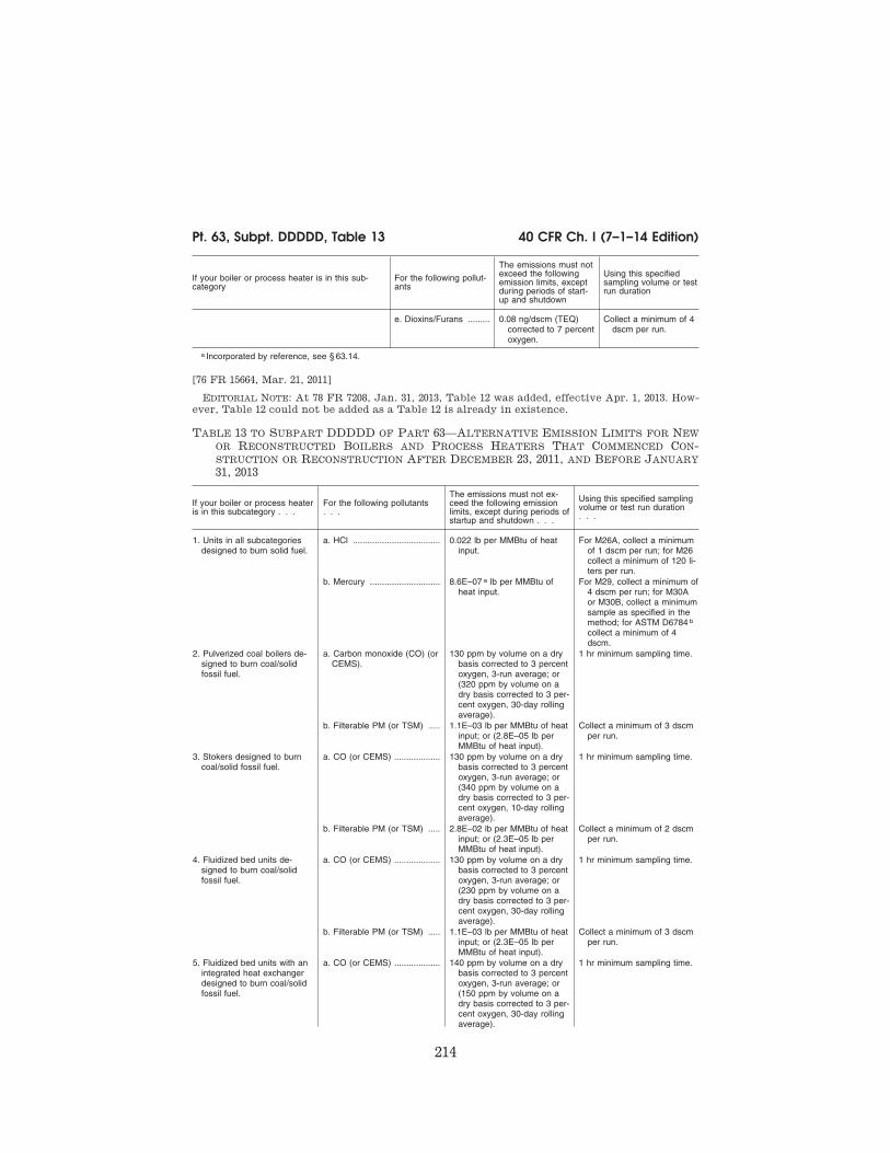
214
40 CFR Ch. I (7–1–14 Edition) Pt. 63, Subpt. DDDDD, Table 13
If your boiler or process heater is in this sub-category
For the following pollut-ants
The emissions must not exceed the following emission limits, except during periods of start-up and shutdown
Using this specified sampling volume or test run duration
e. Dioxins/Furans ......... 0.08 ng/dscm (TEQ) corrected to 7 percent oxygen.
Collect a minimum of 4 dscm per run.
a Incorporated by reference, see § 63.14.
[76 FR 15664, Mar. 21, 2011]
EDITORIAL NOTE: At 78 FR 7208, Jan. 31, 2013, Table 12 was added, effective Apr. 1, 2013. How-
ever, Table 12 could not be added as a Table 12 is already in existence.
TABLE 13 TO SUBPART DDDDD OF PART 63—ALTERNATIVE EMISSION LIMITS FOR NEW
OR RECONSTRUCTED BOILERS AND PROCESS HEATERS THAT COMMENCED CON-
STRUCTION OR RECONSTRUCTION AFTER DECEMBER 23, 2011, AND BEFORE JANUARY
31, 2013
If your boiler or process heater is in this subcategory . . .
For the following pollutants . . .
The emissions must not ex-ceed the following emission limits, except during periods of startup and shutdown . . .
Using this specified sampling volume or test run duration . . .
1. Units in all subcategories designed to burn solid fuel.
a. HCl .................................... 0.022 lb per MMBtu of heat input.
For M26A, collect a minimum of 1 dscm per run; for M26 collect a minimum of 120 li-ters per run.
b. Mercury ............................. 8.6E–07 a lb per MMBtu of heat input.
For M29, collect a minimum of 4 dscm per run; for M30A or M30B, collect a minimum sample as specified in the method; for ASTM D6784 b collect a minimum of 4 dscm.
2. Pulverized coal boilers de-signed to burn coal/solid fossil fuel.
a. Carbon monoxide (CO) (or CEMS).
130 ppm by volume on a dry basis corrected to 3 percent oxygen, 3-run average; or (320 ppm by volume on a dry basis corrected to 3 per-cent oxygen, 30-day rolling average).
1 hr minimum sampling time.
b. Filterable PM (or TSM) ..... 1.1E–03 lb per MMBtu of heat input; or (2.8E–05 lb per MMBtu of heat input).
Collect a minimum of 3 dscm per run.
3. Stokers designed to burn coal/solid fossil fuel.
a. CO (or CEMS) ................... 130 ppm by volume on a dry basis corrected to 3 percent oxygen, 3-run average; or (340 ppm by volume on a dry basis corrected to 3 per-cent oxygen, 10-day rolling average).
1 hr minimum sampling time.
b. Filterable PM (or TSM) ..... 2.8E–02 lb per MMBtu of heat input; or (2.3E–05 lb per MMBtu of heat input).
Collect a minimum of 2 dscm per run.
4. Fluidized bed units de-signed to burn coal/solid fossil fuel.
a. CO (or CEMS) ................... 130 ppm by volume on a dry basis corrected to 3 percent oxygen, 3-run average; or (230 ppm by volume on a dry basis corrected to 3 per-cent oxygen, 30-day rolling average).
1 hr minimum sampling time.
b. Filterable PM (or TSM) ..... 1.1E–03 lb per MMBtu of heat input; or (2.3E–05 lb per MMBtu of heat input).
Collect a minimum of 3 dscm per run.
5. Fluidized bed units with an integrated heat exchanger designed to burn coal/solid fossil fuel.
a. CO (or CEMS) ................... 140 ppm by volume on a dry basis corrected to 3 percent oxygen, 3-run average; or (150 ppm by volume on a dry basis corrected to 3 per-cent oxygen, 30-day rolling average).
1 hr minimum sampling time.
VerDate Sep<11>2014 13:42 Oct 28, 2014 Jkt 232162 PO 00000 Frm 00224 Fmt 8010 Sfmt 8002 Y:\SGML\232162.XXX 232162wre
ier-
avile
s on
DS
K5T
PT
VN
1PR
OD
with
CF
R
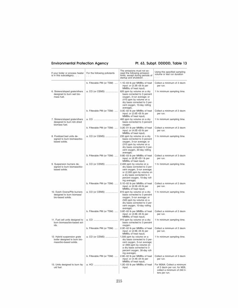
215
Environmental Protection Agency Pt. 63, Subpt. DDDDD, Table 13
If your boiler or process heater is in this subcategory . . .
For the following pollutants . . .
The emissions must not ex-ceed the following emission limits, except during periods of startup and shutdown . . .
Using this specified sampling volume or test run duration . . .
b. Filterable PM (or TSM) ..... 1.1E–03 lb per MMBtu of heat input; or (2.3E–05 lb per MMBtu of heat input).
Collect a minimum of 3 dscm per run.
6. Stokers/sloped grate/others designed to burn wet bio-mass fuel.
a. CO (or CEMS) ................... 620 ppm by volume on a dry basis corrected to 3 percent oxygen, 3-run average; or (410 ppm by volume on a dry basis corrected to 3 per-cent oxygen, 10-day rolling average).
1 hr minimum sampling time.
b. Filterable PM (or TSM) ..... 3.0E–02 lb per MMBtu of heat input; or (2.6E–05 lb per MMBtu of heat input).
Collect a minimum of 2 dscm per run.
7. Stokers/sloped grate/others designed to burn kiln-dried biomass fuel.
a. CO ..................................... 460 ppm by volume on a dry basis corrected to 3 percent oxygen.
1 hr minimum sampling time.
b. Filterable PM (or TSM) ..... 3.2E–01 lb per MMBtu of heat input; or (4.0E–03 lb per MMBtu of heat input).
Collect a minimum of 2 dscm per run.
8. Fluidized bed units de-signed to burn biomass/bio- based solids.
a. CO (or CEMS) ................... 230 ppm by volume on a dry basis corrected to 3 percent oxygen, 3-run average; or (310 ppm by volume on a dry basis corrected to 3 per-cent oxygen, 30-day rolling average).
1 hr minimum sampling time.
b. Filterable PM (or TSM) ..... 9.8E–03 lb per MMBtu of heat input; or (8.3E–05 a lb per MMBtu of heat input).
Collect a minimum of 3 dscm per run.
9. Suspension burners de-signed to burn biomass/bio- based solids.
a. CO (or CEMS) ................... 2,400 ppm by volume on a dry basis corrected to 3 per-cent oxygen, 3-run average; or (2,000 ppm by volume on a dry basis corrected to 3 percent oxygen, 10-day roll-ing average).
1 hr minimum sampling time.
b. Filterable PM (or TSM) ..... 5.1E–02 lb per MMBtu of heat input; or (6.5E–03 lb per MMBtu of heat input).
Collect a minimum of 2 dscm per run.
10. Dutch Ovens/Pile burners designed to burn biomass/ bio-based solids.
a. CO (or CEMS) ................... 810 ppm by volume on a dry basis corrected to 3 percent oxygen, 3-run average; or (520 ppm by volume on a dry basis corrected to 3 per-cent oxygen, 10-day rolling average).
1 hr minimum sampling time.
b. Filterable PM (or TSM) ..... 3.6E–02 lb per MMBtu of heat input; or (3.9E–05 lb per MMBtu of heat input).
Collect a minimum of 2 dscm per run.
11. Fuel cell units designed to burn biomass/bio-based sol-ids.
a. CO ..................................... 910 ppm by volume on a dry basis corrected to 3 percent oxygen.
1 hr minimum sampling time.
b. Filterable PM (or TSM) ..... 2.0E–02 lb per MMBtu of heat input; or (2.9E–05 lb per MMBtu of heat input).
Collect a minimum of 2 dscm per run.
12. Hybrid suspension grate boiler designed to burn bio-mass/bio-based solids.
a. CO (or CEMS) ................... 1,500 ppm by volume on a dry basis corrected to 3 per-cent oxygen, 3-run average; or (900 ppm by volume on a dry basis corrected to 3 percent oxygen, 30-day roll-ing average).
1 hr minimum sampling time.
b. Filterable PM (or TSM) ..... 2.6E–02 lb per MMBtu of heat input; or (4.4E–04 lb per MMBtu of heat input).
Collect a minimum of 3 dscm per run.
13. Units designed to burn liq-uid fuel.
a. HCl .................................... 1.2E–03 lb per MMBtu of heat input.
For M26A: Collect a minimum of 2 dscm per run; for M26, collect a minimum of 240 li-ters per run.
VerDate Sep<11>2014 13:42 Oct 28, 2014 Jkt 232162 PO 00000 Frm 00225 Fmt 8010 Sfmt 8002 Y:\SGML\232162.XXX 232162wre
ier-
avile
s on
DS
K5T
PT
VN
1PR
OD
with
CF
R

216
40 CFR Ch. I (7–1–14 Edition) Pt. 63, Subpt. DDDDD, Table 13
If your boiler or process heater is in this subcategory . . .
For the following pollutants . . .
The emissions must not ex-ceed the following emission limits, except during periods of startup and shutdown . . .
Using this specified sampling volume or test run duration . . .
b. Mercury ............................. 4.9E–07 a lb per MMBtu of heat input.
For M29, collect a minimum of 4 dscm per run; for M30A or M30B, collect a minimum sample as specified in the method; for ASTM D6784 b collect a minimum of 4 dscm.
14. Units designed to burn heavy liquid fuel.
a. CO (or CEMS) ................... 130 ppm by volume on a dry basis corrected to 3 percent oxygen, 3-run average; or (18 ppm by volume on a dry basis corrected to 3 percent oxygen, 10-day rolling aver-age).
1 hr minimum sampling time.
b. Filterable PM (or TSM) ..... 1.3E–03 lb per MMBtu of heat input; or (7.5E–05 lb per MMBtu of heat input).
Collect a minimum of 3 dscm per run.
15. Units designed to burn light liquid fuel.
a. CO (or CEMS) ................... 130 a ppm by volume on a dry basis corrected to 3 percent oxygen; or (60 ppm by vol-ume on a dry basis cor-rected to 3 percent oxygen, 1-day block average)..
1 hr minimum sampling time.
b. Filterable PM (or TSM) ..... 1.1E–03 a lb per MMBtu of heat input; or (2.9E–05 lb per MMBtu of heat input).
Collect a minimum of 3 dscm per run.
16. Units designed to burn liq-uid fuel that are non-conti-nental units.
a. CO ..................................... 130 ppm by volume on a dry basis corrected to 3 percent oxygen, 3-run average based on stack test; or (91 ppm by volume on a dry basis corrected to 3 percent oxygen, 3-hour rolling aver-age).
1 hr minimum sampling time.
b. Filterable PM (or TSM) ..... 2.3E–02 lb per MMBtu of heat input; or (8.6E–04 lb per MMBtu of heat input).
Collect a minimum of 2 dscm per run.
17. Units designed to burn gas 2 (other) gases.
a. CO ..................................... 130 ppm by volume on a dry basis corrected to 3 percent oxygen.
1 hr minimum sampling time.
b. HCl .................................... 1.7E–03 lb per MMBtu of heat input.
For M26A, Collect a minimum of 2 dscm per run; for M26, collect a minimum of 240 li-ters per run.
c. Mercury .............................. 7.9E–06 lb per MMBtu of heat input.
For M29, collect a minimum of 3 dscm per run; for M30A or M30B, collect a minimum sample as specified in the method; for ASTM D6784 b collect a minimum of 3 dscm.
d. Filterable PM (or TSM) ..... 6.7E–03 lb per MMBtu of heat input; or (2.1E–04 lb per MMBtu of heat input).
Collect a minimum of 3 dscm per run.
a If you are conducting stack tests to demonstrate compliance and your performance tests for this pollutant for at least 2 con-secutive years show that your emissions are at or below this limit and you are not required to conduct testing for CEMS or CPMS monitor certification, you can skip testing according to § 63.7515 if all of the other provision of § 63.7515 are met. For all other pollutants that do not contain a footnote ‘‘a’’, your performance tests for this pollutant for at least 2 consecutive years must show that your emissions are at or below 75 percent of this limit in order to qualify for skip testing.
b Incorporated by reference, see § 63.14.
[78 FR 7210, Jan. 31, 2013]
VerDate Sep<11>2014 13:42 Oct 28, 2014 Jkt 232162 PO 00000 Frm 00226 Fmt 8010 Sfmt 8026 Y:\SGML\232162.XXX 232162wre
ier-
avile
s on
DS
K5T
PT
VN
1PR
OD
with
CF
R