adiabatic compressed air energy storage: an analysis on
TRANSCRIPT
Copyright 2019 by the authors. This is an Open Access article distributed under the terms of the Creative Commons Attribution 4.0 Unported (CC BY 4.0) License (https://creativecommons.org/licenses/by/4.0/), allowing third parties to copy and redistribute the material in any medium or format and to remix, transform, and build upon the material for any purpose, even commercially, provided the original work is properly cited and states its license. Citation: TBC
Adiabatic Compressed Air Energy Storage: An analysis on the effect of thermal energy storage insulation thermal conductivity on round-trip efficiency
Simon Tan1, * and Andrew Wahlen2
University of Technology Sydney, Faculty of Science, PO Box 123, Ultimo NSW 2017, Australia 1 [email protected] 2 [email protected] * Author to whom correspondence should be addressed.
DOI: https://doi.org/10.5130/pamr.v6i0.1547
Abstract: Compressed Air Energy Storage (CAES) has demonstrated promising potential for widescale use in the power distribution network, especially where renewables are concerned. Current plants are inefficient when compared to other technologies such as battery and pumped hydro. Presently, the greatest round-trip efficiency of any commercial CAES plant is 54% (McIntosh Plant), while the highest energy efficiency of any experimental plant is 66-70% (ADELE Project). So far, Adiabatic CAES systems have yielded promising results with round-trip efficiencies generally ranging between 65-75%, with some small-scale system models yielding round-trip efficiencies exceeding 90%. Thus far, minimal research has been devoted to analysing the thermodynamic effects of the thermal energy storage (TES) insulation. This meta-study identifies current industry and research trends pertaining to ACAES with a focus on the TES insulation supported by model simulations. Charged standby time and insulation of the TES on overall system efficiency was determined by performing a thermodynamic analysis of an ACAES system using packed bed heat exchangers (PBHE) for TES. The results provide insight into the effect various insulators, including concrete, glass wool and silica-aerogel, have on exergy loss in the TES and overall system efficiency. TES insulation should be carefully considered and selected according to the expected duration of fully charged standby time of the ACAES system. Keywords: Compressed air energy storage; adiabatic compressed air energy storage; thermal energy storage; thermodynamic efficiency; renewable energy storage, packed bed heat exchanger

PAM Review 2019 56
Table 1. Nomenclature.
1. Introduction
Power generation from renewable energy sources such as solar and wind has been increasing significantly over recent years. While there are many important benefits of renewable energy, one of the primary drawbacks of many renewable sources is the fluctuation in power output throughout the day [1]. To address energy storage systems must be employed [2]. Energy storage systems include pumped hydro, lithium batteries, liquid air energy storage, hydrogen energy storage, and compressed air energy storage (CAES) [3,4]. In contrast to other energy storage technologies, CAES has several important advantages. It is clean and sustainable with the potential for high energy capacity and long-term energy storage capabilities. Furthermore, it may be implemented in geological locations where other energy storage technologies such as pumped hydro may be unsuitable. These advantages, coupled with its reasonable cost of implementation, have contributed to the significant attention CAES has received over recent years [5]. However, a major drawback for conventional (diabatic) CAES systems is their poor thermal efficiency when compared to other energy storage solutions such as pumped hydro or lithium batteries. CAES plants discard the thermal energy produced during the compression stages to the environment, therefore requiring the use of fossil fuels to re-heat the air during the expansion phase [6] (see figure 1). This drastically lowers the maximum achievable efficiency of the system. As of April 2019, there are only two commercial CAES plants in operation, located in Huntorf, Germany (in operation since 1978), and McIntosh, USA (operating since 1991). The round-trip efficiencies of the plants are 42% and 54% respectively [5]. To improve the performance of conventional CAES, a range of systems have been proposed. These systems include biomass fuelled CAES, isobaric adiabatic CAES with combined cycle and constant-pressure CAES. While some of these system models can yield high efficiencies, such as isothermal CAES, they are not practical for commercial use due to the very low speed at which the system must operate. A commercially feasible system demonstrating promising efficiency is adiabatic CAES (ACAES) [8]. Unlike conventional CAES, ACAES stores the heat produced during compression and uses it to reheat the gas during the expansion phase, eliminating the need for burning fuels (see figure 2). This has the benefit of significantly increasing overall efficiency while also eliminating the use of non-renewable fuels.
ACAES Adiabatic Compressed Air Energy Storage CAES Compressed Air Energy Storage TES Thermal Energy Storage HP High Pressure PBHE Packed Bed Heat Exchanger DCHE Direct-Contact Heat Exchanger ICHE Indirect-Contact Heat Exchanger

PAM Review 2019
PAM Review 2019
57
Figure 1. A schematic of a conventional (diabatic) CAES system with 2-stage compression and expansion. Fossil fuels are used to re-heat air during expansion process [7].
Figure 2. A schematic of an ACAES system. A thermal energy storage system is used to store heat during compression which is used to reheat air during the expansion process [7].
The primary components of an ACAES system are the compressor(s), turbine(s), thermal energy storage (TES) and compressed air cavern. The compressor and turbine have been identified as the greatest cause of exergy destruction within the system throughout the thermodynamic analysis’ reviewed. While research suggests improving the efficiency of these components, a certain portion of the exergy loss cannot be eliminated due to the irreversibility of real-world systems [8].

PAM Review 2019 58
The majority of papers analysed contained a thermodynamic analysis of an ACAES plant featuring models with varying plant configurations. Variations include the number of compression and expansion stages, operating parameters, types of TES. It was observed that from 24 papers reviewed, the modelling of TES insulation across ACAES research can be categorised as shown in Table 2. The distribution can be seen in figure 3.
Table 2. Categorisation of TES insulation modelling across existing ACAES.
Modelling of TES insulation across ACAES research Number of sources References Assumes ideal TES (100% efficiency) 5 [9-13] Assigns TES a fixed efficiency 12 [14-17] Efficiency of TES modelled as dependent on multiple parameters including Thermal Conductivity
7 [18-24]
Analyses effect of various insulators and fully charged idle time on overall efficiency
0 -
Figure 3. Distribution of ACAES TES insulation modelling
To address this gap in the literature, a simulation model was constructed based on an open-source MATLAB model developed by Barbour et al [24]. Barbour’s model was originally developed for exergy analysis of an ACAES system with packed-thermal-bed TES. This model was adapted to test the effect of differing insulation materials and fully charged idle times on overall system efficiency. The effect of exergy destruction in the TES and overall efficiency was determined, providing insight which may be of interest to anyone looking to construct an ACAES plant.

PAM Review 2019
PAM Review 2019
59
2. Methods
This meta study draws upon academic literature pertaining to CAES within the context of power generation and distribution. Sources were attained through Scopus, Science Direct, UTS Library, and Google Scholar. Journals used include Applied Energy, Journal of Renewable and Sustainable Energy, Energies, Energy Procedia, Elsevier and Materials Today. Papers less than five years old were given preference, although older papers were included if they contained valuable information that wasn’t covered in other papers, such as those providing in-depth analysis of existing CAES plants. Using research analysis tools from Web of Science, it was determined that the first paper submitted to a major journal pertaining to CAES was published in 1984, with only sparse research in this field until the early 2000s. Since 2009, research into CAES systems has increased drastically. See figure A.1 in the Appendix for a histogram of research publications related to CAES since 1984. This increase in research coincides with the rise of global interest in renewable energy [25]. A secondary literature review into ACAES plants was conducted. The majority of papers analysed consisted of a thermodynamic analysis of an ACAES plant featuring simulations of varying plant configurations and operating parameters. Although the first conventional CAES paper was published in 1984, no articles on the topic of ACAES were published in major journals until 2009. Since 2012, this number has increased drastically. See figure A.2 in the Appendix for a histogram of research publications related to ACAES since 2009. After general functionality, capability and performance of conventional CAES systems was determined, research was directed towards ACAES due to its relatively high efficiency and commercial feasibility. Research published on or after 2013 was given preference. Following an analysis of 24 papers with models of ACAES, it was observed that while a significant emphasis has been placed on the exergy destruction taking place during the compression and expansion phases, there were gaps in literature pertaining to the effect of insulation of the TES. While multiple types of TES solutions have been proposed, such as molten salts or packed beds, most papers do not investigate the specifics of the TES insulation.
2.1. Model simulation overview
To test the effect of differing insulation materials and fully charged idle times on overall system efficiency, a simulation model was constructed based on an open-source MATLAB model developed by Barbour et al [24]. This model, originally developed for exergy analysis of an ACAES system with packed-thermal-bed TES, was selected as it was deemed reliable due to the analytical validation of the numerical methods used. The accompanying paper has been cited over 60 times as of May 2019. Furthermore, the construction of the model and selection of key operating parameters corresponded with current industry trends [24]. As our investigation focuses on TES insulation specifically, a detailed description of the compression and expansion processes have been excluded from the body of the paper. These processes are detailed in the model provided by Barbour et al [24].
PAM Review 2019 60
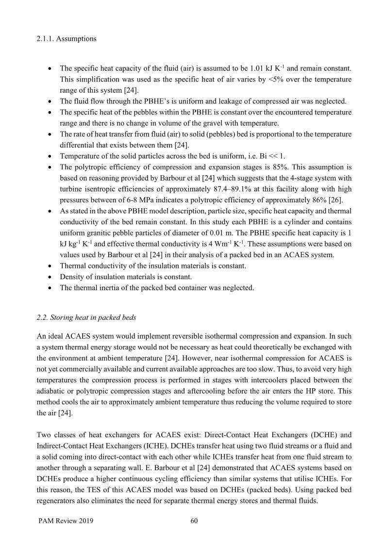
2.1.1. Assumptions
• The specific heat capacity of the fluid (air) is assumed to be 1.01 kJ K-1 and remain constant.
This simplification was used as the specific heat of air varies by <5% over the temperature range of this system [24].
• The fluid flow through the PBHE’s is uniform and leakage of compressed air was neglected. • The specific heat of the pebbles within the PBHE is constant over the encountered temperature
range and there is no change in volume of the gravel with temperature. • The rate of heat transfer from fluid (air) to solid (pebbles) bed is proportional to the temperature
differential that exists between them [24]. • Temperature of the solid particles across the bed is uniform, i.e. Bi << 1. • The polytropic efficiency of compression and expansion stages is 85%. This assumption is
based on reasoning provided by Barbour et al [24] which suggests that the 4-stage system with turbine isentropic efficiencies of approximately 87.4–89.1% at this facility along with high pressures between of 6-8 MPa indicates a polytropic efficiency of approximately 86% [26].
• As stated in the above PBHE model description, particle size, specific heat capacity and thermal conductivity of the bed remain constant. In this study each PBHE is a cylinder and contains uniform granitic pebble particles of diameter of 0.01 m. The PBHE specific heat capacity is 1 kJ kg-1 K-1 and effective thermal conductivity is 4 Wm-1 K-1. These assumptions were based on values used by Barbour et al [24] in their analysis of a packed bed in an ACAES system.
• Thermal conductivity of the insulation materials is constant. • Density of insulation materials is constant. • The thermal inertia of the packed bed container was neglected.
2.2. Storing heat in packed beds
An ideal ACAES system would implement reversible isothermal compression and expansion. In such a system thermal energy storage would not be necessary as heat could theoretically be exchanged with the environment at ambient temperature [24]. However, near isothermal compression for ACAES is not yet commercially available and current available approaches are too slow. Thus, to avoid very high temperatures the compression process is performed in stages with intercoolers placed between the adiabatic or polytropic compression stages and aftercooling before the air enters the HP store. This method cools the air to approximately ambient temperature thus reducing the volume required to store the air [24]. Two classes of heat exchangers for ACAES exist: Direct-Contact Heat Exchangers (DCHE) and Indirect-Contact Heat Exchangers (ICHE). DCHEs transfer heat using two fluid streams or a fluid and a solid coming into direct-contact with each other while ICHEs transfer heat from one fluid stream to another through a separating wall. E. Barbour et al [24] demonstrated that ACAES systems based on DCHEs produce a higher continuous cycling efficiency than similar systems that utilise ICHEs. For this reason, the TES of this ACAES model was based on DCHEs (packed beds). Using packed bed regenerators also eliminates the need for separate thermal energy stores and thermal fluids.
PAM Review 2019
PAM Review 2019
61
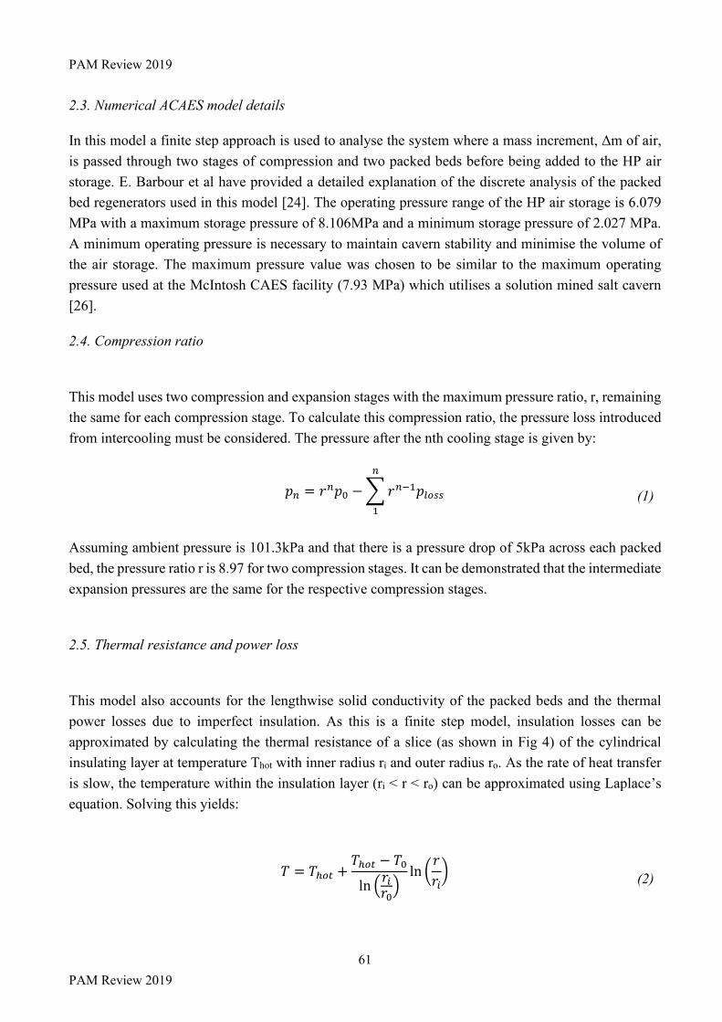
2.3. Numerical ACAES model details
In this model a finite step approach is used to analyse the system where a mass increment, Δm of air, is passed through two stages of compression and two packed beds before being added to the HP air storage. E. Barbour et al have provided a detailed explanation of the discrete analysis of the packed bed regenerators used in this model [24]. The operating pressure range of the HP air storage is 6.079 MPa with a maximum storage pressure of 8.106MPa and a minimum storage pressure of 2.027 MPa. A minimum operating pressure is necessary to maintain cavern stability and minimise the volume of the air storage. The maximum pressure value was chosen to be similar to the maximum operating pressure used at the McIntosh CAES facility (7.93 MPa) which utilises a solution mined salt cavern [26].
2.4. Compression ratio
This model uses two compression and expansion stages with the maximum pressure ratio, r, remaining the same for each compression stage. To calculate this compression ratio, the pressure loss introduced from intercooling must be considered. The pressure after the nth cooling stage is given by:
𝑝" = 𝑟"𝑝% −'𝑟"()𝑝*+,,
"
)
(1)
Assuming ambient pressure is 101.3kPa and that there is a pressure drop of 5kPa across each packed bed, the pressure ratio r is 8.97 for two compression stages. It can be demonstrated that the intermediate expansion pressures are the same for the respective compression stages.
2.5. Thermal resistance and power loss
This model also accounts for the lengthwise solid conductivity of the packed beds and the thermal power losses due to imperfect insulation. As this is a finite step model, insulation losses can be approximated by calculating the thermal resistance of a slice (as shown in Fig 4) of the cylindrical insulating layer at temperature Thot with inner radius ri and outer radius ro. As the rate of heat transfer is slow, the temperature within the insulation layer (ri < r < ro) can be approximated using Laplace’s equation. Solving this yields:
𝑇 = 𝑇.+/ +𝑇.+/ − 𝑇%ln 3𝑟4𝑟%
5ln 6
𝑟𝑟47
(2)

PAM Review 2019 62
The next step is to obtain the thermal resistance and power loss. The thermal resistance and thermal power loss can be found by applying the integral form of Fourier’s law for heat conduction.
𝑄 =𝑇.+/ − 𝑇%𝑅/.
(3)
This approach is valid providing that the thermal conductivity and thickness are constant throughout the material.
𝑅/. =
ln 3𝑟%𝑟45
2𝜋∆𝑧𝜆
(4)
Here Δz is the height of each packed bed slice and λ is the thermal conductivity of the insulation material used.
2.6. Exergy loss due to thermal power loss
This model estimates exergy loss due to loss of thermal power. It is assumed that all available work (exergy) lost could have been used to generate reversible work and all the exergy lost is transferred directly to the environment at temperature T0. A more advanced analysis would acknowledge that work cannot be produced reversibly and thus heat will be generated and flow into other components of the system as a result of this generated work. Thus, not all exergy would be lost to the environment. A detailed explanation is provided in Appendix A of [27]. With the aforementioned simplifications outlined the exergy loss resulting from heat transfer to the ambient environment (at temperature T0) from a system at temperature T is given by:
�̇�.AB/*+,, = 61 −𝑇%𝑇7 �̇� (5)
Over time, the temperature of the bed will decrease as heat flows out. This rate is expressed by:
𝛿𝐵.AB/*+,, = 61 −𝑇%𝑇7 𝛿𝑄 (6)
Exergy loss resulting from the bed cooling from T1 to T2 can then be approximated by assuming a constant specific heat capacity of the bed (δQ becomes mcδT) and integrating over this temperature range.

PAM Review 2019
PAM Review 2019
63
𝐵.AB/*+,, = 𝑚𝑐𝑇% 6
𝑇)𝑇%−𝑇H𝑇%− ln
𝑇)𝑇H7 (7)
2.7. Pressure loss
Pressure losses in the packed beds are inevitable. In this model, pressure losses are estimated using the Ergun equation. This method is generally regarded as suitable for an initial estimate, providing that the void fraction of the beds lies within the range 0.33 < e < 0.55. The Ergun equation provides one method of estimating the pressure drop through a packed bed. This estimate is based on an empirical relationship, (some theoretical validation is provided by du Plessis and Woudberg [28]) however, it is generally regarded as suitable for a first estimate, provided that a few conditions are met. These conditions are as follows, the void fraction must be in the range, 0.33 < e < 0.55, the particles within the bed must be similar in size and the air flow rates must be moderate [29]. The Ergun equation states:
Δ𝑝𝐿=150𝜇𝜓H𝑑PH
(1 − 𝜀)H
𝜀T𝑣V +
1.75𝜌V𝜓𝑑P
(1 − 𝜀)𝜀T
𝑣VH (8)
Here dp denotes the diameter of the bed particles, ρf is the air (fluid) density, υf is the superficial bed velocity of the fluid in the bed, µ is the fluid dynamic viscosity, ε is the void fraction of the packed bed and ψ is the shape factor. The shape factor is used to correct for the non-spherical nature of the granitic gravel pieces. This is done by finding the equivalent spherical particle diameter using the product ψ∙dp. The shape factor ψ is given by:
𝜓 =6𝑣P𝐴P𝑑P
(9)
2.8. Cycle efficiency
The final step is to determine the efficiency of the cycle:
𝜂 =𝑤_4,`.BabA𝑤`.BabA
(10)
where Wcharge is the total compressive work required and Wdischarge is the total useful work generated by the expansion. The system exergy balance is as follows:
𝑊`.BabA = 𝑊_4,`.BabA + 𝐵_,`+eP + 𝐵_,fgh + 𝐵*+,/,Ai4/ + 𝐵*+,/,jk + 𝐵_,jk (11)

PAM Review 2019 64
Where Bd,comp is exergy destroyed during compression, Bd,exp is exergy destroyed during expansion and Blost,exit is the exergy in the exhaust gas that remains after the final expansion. Details of the model used to estimate these values can be found under section 2.1 Compression and Expansion of [24]. Exergy losses resulting from the packed beds include Blost,PB which is estimated by Eq.7 and denotes the exergy lost as heat and Bd,PB which denotes the exergy destroyed due to pressure losses and lengthwise conduction of heat along the bed.
Table 3. Operating parameters of the ACAES model [24].
Parameter Value Ambient Temperature (K) 290 Ambient Pressure (kPa) 101.325 Specific Heat of Air (kJ/(kg∙K)) 1.01 Gas Constant R (J/(mol∙K)) 8.314 Adiabatic Index (Ratio of Specific Heats) 1.4 Charge Time (h) 4 Number of Stages 2 Polytropic Efficiency of Compressors 0.85 Polytropic Efficiency of Turbines 0.85 Initial Pressure of Store (MPa) 2.027 Final Pressure of Store (MPa) 8.106 Storage Temperature (K) 290 Work Input (kWh) 2000 Specific Heat of Packed Bed Pebbles (kJ/(kg∙K)) 1.000 Thermal Conductivity of Pebbles (W/(m∙K)) 4 Length of Packed Bed (m) 12 Radius of Packed Bed (m) 0.6 Length of Packed Bed Slices (m) 0.02 Diameter of Packed Bed Pebbles (m) 0.01 Insulation Thickness (m) 0.2 Packed Bed Void Fraction 0.36
3. Results and Discussion
Thermal conductivity is a function of temperature which varies depending on the material. The maximum temperature of the TES when the system has come to steady state at the end of a full charge is 713K. The model simulation was run using six different insulating materials at 713K. A wide range of insulators were selected, with thermal conductivities ranging from as low as 0.065 W/(m∙K) (silica aerogels) to as high as Pyrex 7740, which has a thermal conductivity of 1.62 W/(m∙K) at 713K. The materials and properties have been listed in Table 4. The model simulation was run for each of the six

PAM Review 2019
PAM Review 2019
65
materials at fully charged idle times ranging from 0-48 hours at 2-hour intervals totalling 150 simulations.
Table 4. Thermal conductivity of TES insulators
Material Density Thermal conductivity (mW/(m∙K)) at 713K
Silica aerogels [30] 185 kg/m3 65 Pyrex 7740 [31] 2230 kg/m3 1620 Insulating firebrick - NC-26 [32] 2050 kg/m3 260 Glass wool - AES glass fibre [33] 139 kg/m3 100 Polycrystalline Al2O3 sol-gel fibre panel [33] 200 kg/m3 80
Concrete [34] 2400 kg/m3 1000
Figure 4. Effect of idle time on exergy destruction in TES. (Graph order corresponds to legend from top to bottom).
The exergy loss in the TES (see figure 5) is dependent on the thermal conductivity of the insulators and the time for which the system remains charged. A larger thermal conductivity results in a greater loss of exergy. As the TES cools down, the rate of exergy loss will also decrease. Therefore, the

PAM Review 2019 66
relationship between exergy loss and time is non-linear. The round-trip efficiency (see equation 10), has also been determined for each of insulating materials over 0-48 hours (See figure 6). The round-trip efficiency ranged from 69.2% - 77.1% for an idle time of 0 hrs (i.e. the system begins to discharge as soon as it finishes charging, depending on the thermal conductivity of the insulator. The disparity between the most efficient and least efficient insulators increased significantly as the idle time increased. The round-trip efficiency of the system with concrete as the TES insulator dropped from 72.2% to 44.4% over 48 hours, while the round-trip efficiency of the system using silica aerogels to insulate the TES dropped from 77.1% to 71.1%. This demonstrates the significant effect of both the thermal conductivity of the TES insulator and the time at which the system remains fully charged on the overall efficiency of the system.
Figure 5. Effect of idle time on round-trip efficiency of ACAES model. (Graph order corresponds to legend from top to bottom).
It was also observed from figure 6 that if the thermal conductivities of the insulators were relatively similar, for example between silica aerogels and glass wool, the difference in round trip efficiency was very small when the idle time was low. For a 4-hour idle time, the efficiency difference between silica aerogels and glass wool was 0.4%. The efficiency differential increased to 2.3% over the 48-hour idle period.

PAM Review 2019
PAM Review 2019
67
It can also be observed that while the round-trip efficiency of the ACAES plant greatly exceeds the efficiency of conventional CAES plants for short idle times (less than 10 hours), the efficiency difference is reduced as the idle time increases. Furthermore, if the TES cools down too much, the air will not be sufficiently reheated prior to expansion, which may cause further complications [35]. These issues are rather unique to ACAES and are not present in other energy storage systems such as conventional CAES or pumped hydro. Hence, ACAES systems are most suitable for short term energy storage. One potential usage could be with renewables such as solar power, which only generates electricity during sunlight hours. There has also been recent research into developing new thermal insulation material, which is focused on reducing thermal conductivity, reducing financial cost and increasing service life [36]. Furthermore, there has been research into developing thermal insulation using renewable resources, such as hemp-based insulators [37]. While an optimal insulator will reduce exergy losses, there is a trade-off between the material cost and improvement to round-trip efficiency. Another way to prevent heat loss is increasing the thickness of the insulation. Research has been conducted into determining the optimal usage of insulators using a life cycle cost analysis. The optimal cost/benefit point for the insulators will largely depend on the charge and discharge cycles of the plant. Therefore, it is important that this is carefully modelled [38]. One limitation of our analysis is that the thermal conductivity of the materials analysed is taken to be a fixed value in that it does not vary with temperature. The thermal conductivity of the materials was taken at the maximum operating temperature of the TES. Data from which such functions may be derived were not easily located and therefore must be determined experimentally. This would have a notable effect on the estimated exergy loss of the system, especially for lengthy fully charged idle times. The point of the study, however, was to determine notable trends, and to determine areas where future research should be directed. A detailed thermodynamic analysis focused on TES insulation within an ACAES system should be conducted using a realistic model prior to development of an ACAES plant. This is especially important if extended fully charged idle times are anticipated [18]. Furthermore, technological advances in available insulating materials should be considered for use in the TES.
4. Conclusions
The objective of the analysis was to determine the effect of varying thermal conductivities on the efficiency of an ACAES system. While ACAES systems may certainly be a viable option for short term energy storage, they may be unsuitable for long term energy storage as there is no combustion process to re-heat the air if the TES cools down too much over time. Thermal conductivity of TES insulation and the time for which the ACAES system remains fully charged have a significant effect on overall system efficiency. A detailed thermodynamic analysis focused on TES insulation of an ACAES system should be conducted using a realistic model. This is especially important if extended

PAM Review 2019 68
fully charged idle times are anticipated for a particular plant. Future research should include modelling thermal conductivity of the TES insulators as a function of temperature and experimenting with various thicknesses to achieve optimal outcomes. Future research should also consider comparing emerging insulation technologies for the TES against existing insulation technologies.
Acknowledgments
The authors would like to thank Dr Jurgen Schulte and Liam Martin and our peers for their assistance in creating, refining and publishing this paper. The authors would also like to thank the UTS library staff for their assistance with database and referencing services.

PAM Review 2019
PAM Review 2019
69
References
1. Dahash A, Ochs F, Janetti MB, Streicher W. Advances in seasonal thermal energy storage for solar district heating applications: A critical review on large-scale hot-water tank and pit thermal energy storage systems. Appl Energy 2019:296-315.
2. Haikarainen C, Pettersson F, Saxén H. Optimising the regional mix of intermittent and flexible energy technologies. J Clean Prod 2019;219:508-517.
3. Yazdani S, Deymi-Dashtebayaz M, Salimipour E. Comprehensive comparison on the ecological performance and environmental sustainability of three energy storage systems employed for a wind farm by using an emergy analysis. Energy Convers Manage 2019;191:1-11.
4. Eshraghi A, Salehi G, Heibati S, Lari K. An assessment of the effect of different energy storage technologies on solar power generators for different power sale scenarios: The case of Iran. Sustainable Energy Technol Assess 2019;34:62-67.
5. Wang J, Lu K, Ma L, Wang J, Dooner M, Miao S, et al. Overview of compressed air energy storage and technology development. Energies 2017;10(7).
6. Advanced Adiabatic Compressed air Energy Storage Energy in Air. Proceedings of the 4th International Conference on Electrical Energy Systems, ICEES 2018; 2018.
7. Aghahosseini A, Breyer C. Assessment of geological resource potential for compressed air energy storage in global electricity supply. Energy Convers Manage 2018;169:161-173.
8. Liu H, He Q, Saeed SB. Thermodynamic analysis of a compressed air energy storage system through advanced exergetic analysis. J Renewable Sustainable Energy 2016;8(3).
9. Grazzini G, Milazzo A. Thermodynamic analysis of CAES/TES systems for renewable energy plants. Renew Energy 2008;33(9):1998-2006.
10. Liu H, He Q, Saeed SB. Thermodynamic analysis of a compressed air energy storage system through advanced exergetic analysis. J Renewable Sustainable Energy 2016;8(3).
11. Safaei H, Aziz MJ. Thermodynamic analysis of three compressed air energy storage systems: Conventional, adiabatic, and hydrogen-fueled. Energies 2017;10(7).
12. Han Z, Guo S, Wang S, Li W. Thermodynamic analyses and multi-objective optimization of operation mode of advanced adiabatic compressed air energy storage system. Energy Conversion and Management 2018;174:45-53.
13. Li Y, Wang X, Li D, Ding Y. A trigeneration system based on compressed air and thermal energy storage. Applied Energy 2012;99:316-323.
14. Mozayeni H, Wang X, Negnevitsky M. Exergy analysis of a one-stage adiabatic compressed air energy storage system. Energy Procedia 2019;160:260-267.
15. Mozayeni H, Negnevitsky M, Wang X, Cao F, Peng X. Performance Study of an Advanced Adiabatic Compressed Air Energy Storage System. Energy Procedia 2017;110:71-76.
16. Yang K, Zhang Y, Li X, Xu J. Theoretical evaluation on the impact of heat exchanger in Advanced Adiabatic Compressed Air Energy Storage system. Energy Conversion and Management 2014;86:1031-1044.
17. Zhang Y, Yang K, Li X, Xu J. The thermodynamic effect of thermal energy storage on compressed air energy storage system. Renewable Energy 2013;50:227-235.
18. Guo C, Zhang K, Pan L, Cai Z, Li C, Li Y. Numerical investigation of a joint approach to thermal energy storage and compressed air energy storage in aquifers. Appl Energy 2017;203:948-958.
19. Guo C, Xu Y, Zhang X, Guo H, Zhou X, Liu C, et al. Performance analysis of compressed air energy storage systems considering dynamic characteristics of compressed air storage. Energy 2017;135:876-888.

PAM Review 2019 70
20. White AJ, McTigue JD, Markides CN. Analysis and optimisation of packed-bed thermal reservoirs for electricity storage applications. Proc Inst Mech Eng Part A J Power Eng 2016;230(7):739-754.
21. Li R, Wang H, Tu Q. Thermo-Economic Analysis and Optimization of Adiabatic Compressed Air Energy Storage (A-CAES) System Coupled with a Kalina Cycle. Energy Technol 2018;6(6):1011-1025.
22. Han Z, Guo S. Investigation of operation strategy of combined cooling, heating and power(CCHP) system based on advanced adiabatic compressed air energy storage. Energy 2018;160:290-308.
23. Wang S, Zhang X, Yang L, Zhou Y, Wang J. Experimental study of compressed air energy storage system with thermal energy storage. Energy 2016;103:182-191.
24. Barbour E, Mignard D, Ding Y, Li Y. Adiabatic Compressed Air Energy Storage with packed bed thermal energy storage. Appl Energy 2015;155:804-815. Figure 4 licenced under CC BY 4.0.
25. Espécie MDA, de Carvalho PN, Pinheiro MFB, Rosenthal VM, da Silva, L. A. F., Pinheiro, M. R. D. C., et al. Ecosystem services and renewable power generation: A preliminary literature review. Renew Energy 2019:39-51.
26. Nakhamkin M, Andersson L, Swensen E, Howard J, Meyer R, Schainker R, et al. Aec 110 mw caes plant: Status of project. J Eng Gas Turbines Power 1992;114(4):695-700.
27. Badescu V. Optimal paths for minimizing lost available work during usual heat transfer processes. J Non Equilib Thermodyn 2004;29(1):53-73.
28. du Plessis JP, Woudberg S. Pore-scale derivation of the Ergun equation to enhance its adaptability and generalization. Chem Eng Sci 2008;63(9):2576-2586.
29. Nemec D, Levec J. Flow through packed bed reactors: 1. Single-phase flow. Chem Eng Sci 2005;60(24):6947-6957.
30. He Y, Xie T. Advances of thermal conductivity models of nanoscale silica aerogel insulation material. Applied Thermal Engineering 2015;81:28-50.
31. Stachowiak G, Batchelor A. Engineering Tribology. Engineering Tribology; 2006. 32. Lee WE, Moore RE. Evolution of in situ refractories in the 20th century. J Am Ceram Soc
1998;81(6):1385-1410. 33. Modarresifar F, Bingham PA, Jubb GA. Thermal conductivity of refractory glass fibres: A
study of materials, standards and test methods. J Therm Anal Calor 2016;125(1):35-44. 34. 34 Kodur V. Properties of concrete at elevated temperatures. ISRN Civ Eng 2014;2014. 35. Safaei H, Aziz MJ. Thermodynamic analysis of three compressed air energy storage systems:
Conventional, adiabatic, and hydrogen-fueled. Energies 2017;10(7). 36. Thinnes B. 'Revolutionary' new industrial insulation product. Hydrocarbon Process 2010;89(8). 37. Kimura R, Ohsumi M, Susanti L. Development of thermal insulation material using coconut
fiber to reuse agricultural industrial waste. Int J Adv Sci Eng Inf Technol 2018;8(3):805-810. 38. Coskun S. Determination of optimum insulation thickness using life cycle cost analysis. Energy
Educ Sct Technol Part A Energy Sci Res 2012;30(SPEC .ISS.1):441-452.

PAM Review 2019
PAM Review 2019
71
Appendix
Figure A.1. Number publications in major journals per year relating to CAES systems since 1982. Research analytics was conducted using Web of Science.
Figure A.2. Number of publications in major journal per year relating to ACAES systems since 2008. Research analytics was conducted using Web of Science.