adjust-o-sealct clean steam trap hc alloy 20 c ½ 4 series 4 g- female cbi7 g tf vi di diverter port...
TRANSCRIPT
2
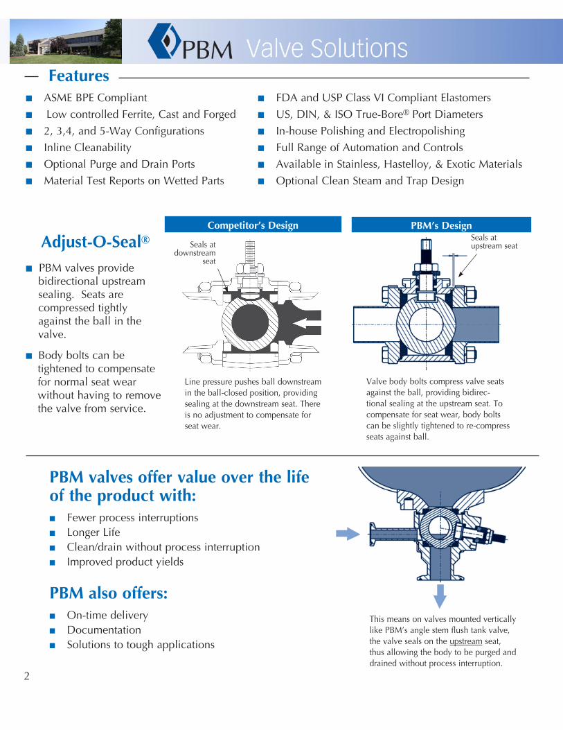
Adjust-O-Seal®
n PBM valves provide bidirectional upstream sealing. Seats are compressed tightly against the ball in the valve.
n Body bolts can be tightened to compensate for normal seat wear without having to remove the valve from service.
Seals at upstream seatSeals at
downstream seat
PBM’sDesignCompetitor’sDesign
Valve body bolts compress valve seats against the ball, providing bidirec-tional sealing at the upstream seat. To compensate for seat wear, body bolts can be slightly tightened to re-compress seats against ball.
Line pressure pushes ball downstream in the ball-closed position, providing sealing at the downstream seat. There is no adjustment to compensate for seat wear.
PBMvalvesoffervalueoverthelifeoftheproductwith:n Fewer process interruptionsn Longer Lifen Clean/drain without process interruptionn Improved product yields
PBMalsooffers:n On-time deliveryn Documentationn Solutions to tough applications
This means on valves mounted vertically like PBM’s angle stem flush tank valve, the valve seals on the upstream seat, thus allowing the body to be purged and drained without process interruption.
Featuresn ASME BPE Compliant n FDA and USP Class VI Compliant Elastomers
n Low controlled Ferrite, Cast and Forged n US, DIN, & ISO True-Bore ® Port Diameters
n 2, 3,4, and 5-Way Configurations n In-house Polishing and Electropolishing
n Inline Cleanability n Full Range of Automation and Controls
n Optional Purge and Drain Ports n Available in Stainless, Hastelloy, & Exotic Materials
n Material Test Reports on Wetted Parts n Optional Clean Steam and Trap Design
3
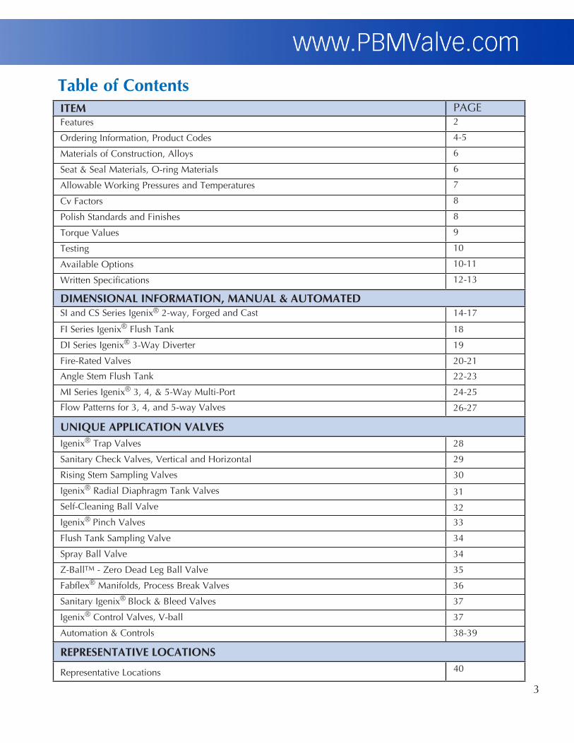
TableofContentsITEM PAGEFeatures 2
Ordering Information, Product Codes 4-5
Materials of Construction, Alloys 6
Seat & Seal Materials, O-ring Materials 6
Allowable Working Pressures and Temperatures 7
Cv Factors 8
Polish Standards and Finishes 8
Torque Values 9
Testing 10
Available Options 10-11
Written Specifications 12-13
DIMENSIONALINFORMATION,MANUAL&AUTOMATEDSI and CS Series Igenix® 2-way, Forged and Cast 14-17
FI Series Igenix® Flush Tank 18
DI Series Igenix® 3-Way Diverter 19
Fire-Rated Valves 20-21
Angle Stem Flush Tank 22-23
MI Series Igenix® 3, 4, & 5-Way Multi-Port 24-25
Flow Patterns for 3, 4, and 5-way Valves 26-27
UNIQUEAPPLICATIONVALVESIgenix® Trap Valves 28
Sanitary Check Valves, Vertical and Horizontal 29
Rising Stem Sampling Valves 30
Igenix® Radial Diaphragm Tank Valves 31
Self-Cleaning Ball Valve 32
Igenix® Pinch Valves 33
Flush Tank Sampling Valve 34
Spray Ball Valve 34
Z-BallTM - Zero Dead Leg Ball Valve 35
Fabflex® Manifolds, Process Break Valves 36
Sanitary Igenix® Block & Bleed Valves 37
Igenix® Control Valves, V-ball 37
Automation & Controls 38-39
REPRESENTATIVELOCATIONS
Representative Locations 40

4
OrderingInformation
VALVE CONFIGURATION ORDERING INFORMATION 1
Number(s) in parentheses indicate valve configuration part number position PBM part numbers can have up to 20 alpha-numeric characters
Part Number Position 1 2 3 4 5 6 7 8 9 10 11 12 13 14 15 16 17 18 19 20
Part Number Code example S I H F E 9 F - G - - - 3 4 A - S X X X
SANITARY VALVES PRODUCT
(1-2) MATERIAL2
(3-4) SIZE (5)
SERIES
(6) END CONNECTION3
(7-8) SEAT & SEAL / FILLERS / O-RINGS (if used)4
(9) SEAT FILLER O-RING
AF Angle Stem C- Hastelloy® C-276 A ¼ 1 Series 1 A- Acme Bevel C VT VI CS Clean Steam H- 316 / 316L Stainless B ⅜ 3 Series 3 F- Ext tube buttweld D VT VT VI CT Clean Steam Trap HC Alloy 20 C ½ 4 Series 4 G- Female CBI7 G TF VI DI Diverter Port HL 316L Stainless D ¾ 5 Series 5 H- Male CBI7 H HT VI DC Diverter (Steam) HF F316L Forged E 1 6 Series 6 I- Swagelok TS I HT VT VI FI Flush Tank H2 317L Stainless G 1½ 8 Series 8 SM Compression J TF VT VI FC Flush Tank (Steam) I- Inconel® 600 H 2 9 Series 9 W- clamp 1” BPE 09 K UT VI MI Multi-Port P- AL6XN J 2½ X- Hygenic clamp L UT VT VI SI Sanitary 2-way T- Gr. 5 Titanium K 3 -Z No end fittings M UT UT VI T2 Gr. 2 Titanium L 4 N PK KA
PV see page 23 T7 Gr. 7 Titanium M 6 Column 8 options O PK VT KA RD see page 24 Y- Hastelloy® C-22® 3 Non Adjust-O-Seal® P PK PK KA S- see page 25 5- Inconel® 625 4 Reduced port R KY VI S2 see page 25 25 254SMO® 6Mo 5 Non Adjust-O-Seal® & S KY KY VI S3 see page 25 21 321 Stainless Reduced port T VT EP
22 Duplex 2205 7 Flat-faced flanges U VT VT EP 76 Super Duplex 32750 / 32760 9 Bar-stock X PC VI 55 Ferralium 255 Z TF EP 0 HT EP
CURRENT PRODUCT SERIES STEAM vs. SEAT COMPATIBILITY 1 HT VT EP 1 AF, PV, RD Bronze DP & MP, Ductile Iron MP VTFE • ≤75psig at ≤320°F 2 TF VT EP 3 AF(Fire-safe API-607) TFM™ / RTFE • ≤150psig at ≤366°F 3 UT EP 4 Stainless & Carbon Steel MP, Stainless MI (300# class maximum) S-TEF® • ≤200psig at ≤388°F 4 UT VT EP 5 AN, DD, DP, FD, FT, Stainless MI8, Stainless MP8, SP, SD PEEK • ≤320psig at ≤425°F 5 UT UT EP
6 AN, FI, SI, SP, FT (Fire-safe API-607) 6 PK VI 6 CN, CP (Fire-Safe API-607), CD (not fire-safe) 7 VT VV
8 & 9 CS, CT, DC, DI, FC, FI, SI 9 TF VV SEAT / SEAL / MATERIAL CODES CG Carbon-Graphite HT S-TEF® KY Kynar®
O-RINGS ARE NOT USED IN ALL VALVE
PRODUCTS – SEE EACH RESPECTIVE
PAGE PC PCTFE (Kel-F) PK PEEK® RT RTFE TF TFM™ UT UHMWPE VT VTFE CG Carbon-Graphite O-RING MATERIAL CODES EP EPR KA Kalrez®® VI Viton™ VV PTFE Encapsulated Viton™
1 - Not all options are available on all valve styles; consult PBM. 2 - For valves with 2 different materials, use the 1st position for body material and the 2nd position for end fitting material. 3 - For valves with 2 different end connections, use both end codes - e.g. - FX = extended buttweld for tube by clamp. 4 - For standard seat/seal material by series, please see appropriate pricing page. PBM may substitute TFM™ for RTFE at our discretion without notice. TFM™ is a registered trademark of Dyneon™ - a 3M Company. 5 - PBM reserves the right to use 922 Bronze in place of 836 Bronze without notification. 6 - All Carbon Steel and Ductile Iron valves may be coated internally and externally with Rust Veto 342, a rust inhibitor. Information on Rust Veto and/or an MSDS is available upon request. If Rust Veto is not acceptable, customer to advise specific coating required. Alternate coatings may impact price and delivery time. In addition, Carbon steel and Ductile Iron cast products are painted (black in color) externally prior to Rust Veto coating. 7 - only available 1” through 6”. 8 -150# class maximum. 9 Requires 17-4PH stem
5
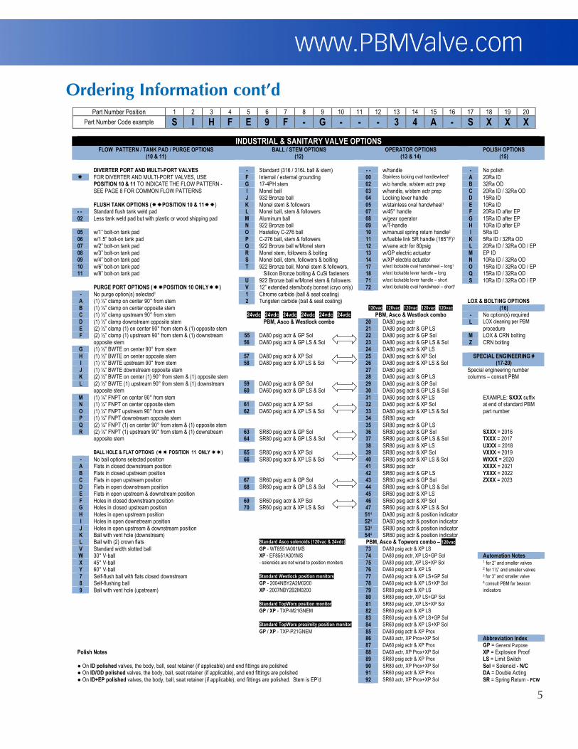
OrderingInformationcont’d
Part Number Position 1 2 3 4 5 6 7 8 9 10 11 12 13 14 15 16 17 18 19 20
Part Number Code example S I H F E 9 F - G - - - 3 4 A - S X X X
INDUSTRIAL & SANITARY VALVE OPTIONS FLOW PATTERN / TANK PAD / PURGE OPTIONS
(10 & 11) BALL / STEM OPTIONS
(12) OPERATOR OPTIONS
(13 & 14) POLISH OPTIONS
(15) DIVERTER PORT AND MULTI-PORT VALVES - Standard (316 / 316L ball & stem) - - w/handle - No polish FOR DIVERTER AND MULTI-PORT VALVES, USE F Internal / external grounding 00 Stainless locking oval handlewheel1 A 20Ra ID POSITION 10 & 11 TO INDICATE THE FLOW PATTERN - G 17-4PH stem 02 w/o handle, w/stem actr prep B 32Ra OD SEE PAGE 8 FOR COMMON FLOW PATTERNS I Monel ball 03 w/handle, w/stem actr prep C 20Ra ID / 32Ra OD J 932 Bronze ball 04 Locking lever handle D 15Ra ID FLUSH TANK OPTIONS (POSITION 10 & 11) K Monel stem & followers 05 w/stainless oval handwheel1 E 10Ra ID - - Standard flush tank weld pad L Monel ball, stem & followers 07 w/45° handle F 20Ra ID after EP 02 Less tank weld pad but with plastic or wood shipping pad M Aluminum ball 08 w/gear operator G 15Ra ID after EP N 922 Bronze ball 09 w/T-handle H 10Ra ID after EP 05 w/1” bolt-on tank pad O Hastelloy C-276 ball 10 w/manual spring return handle2 I 5Ra ID 06 w/1.5” bolt-on tank pad P C-276 ball, stem & followers 11 w/fusible link SR handle (165°F)3 K 5Ra ID / 32Ra OD 07 w/2” bolt-on tank pad Q 922 Bronze ball w/Monel stem 12 w/vane actr for 80psig L 20Ra ID / 32Ra OD / EP 08 w/3” bolt-on tank pad R Monel stem, followers & bolting 13 w/GP electric actuator M EP ID 09 w/4” bolt-on tank pad S Monel ball, stem, followers & bolting 14 w/XP electric actuator N 10Ra ID / 32Ra OD 10 w/6” bolt-on tank pad T 922 Bronze ball, Monel stem & followers, 17 w/ext lockable oval handwheel – long1 O 15Ra ID / 32Ra OD / EP 11 w/8” bolt-on tank pad Silicon Bronze bolting & CuSi fasteners 18 w/ext lockable lever handle – long Q 15Ra ID / 32Ra OD U 922 Bronze ball w/Monel stem & followers 71 w/ext lockable lever handle – short S 10Ra ID / 32Ra OD / EP PURGE PORT OPTIONS (POSITION 10 ONLY) V 12” extended stem/body bonnet (cryo only) 72 w/ext lockable oval handwheel – short1 - No purge option(s) selected1 1 Chrome carbide (ball & seat coating) A (1) ½” clamp on center 90° from stem 2 Tungsten carbide (ball & seat coating) LOX & BOLTING OPTIONS B (1) ½” clamp on center opposite stem 120vac 120vac 120vac 120vac 120vac (16) C (1) ½” clamp upstream 90° from stem 24vdc 24vdc 24vdc 24vdc 24vdc 24vdc PBM, Asco & Westlock combo - No option(s) required D (1) ½” clamp downstream opposite stem PBM, Asco & Westlock combo 20 DA80 psig actr L LOX cleaning per PBM
E (2) ½” clamp (1) on center 90° from stem & (1) opposite stem 21 DA80 psig actr & GP LS procedure F (2) ½” clamp (1) upstream 90° from stem & (1) downstream 55 DA80 psig actr & GP Sol 22 DA80 psig actr & GP Sol M LOX & CRN bolting opposite stem 56 DA80 psig actr & GP LS & Sol 23 DA80 psig actr & GP LS & Sol Z CRN bolting
G (1) ½” BWTE on center 90° from stem 24 DA80 psig actr & XP LS H (1) ½” BWTE on center opposite stem 57 DA80 psig actr & XP Sol 25 DA80 psig actr & XP Sol I (1) ½” BWTE upstream 90° from stem 58 DA80 psig actr & XP LS & Sol 26 DA80 psig actr & XP LS & Sol
SPECIAL ENGINEERING # (17-20)
J (1) ½” BWTE downstream opposite stem 27 DA60 psig actr K (2) ½” BWTE on center (1) 90° from stem & (1) opposite stem 28 DA60 psig actr & GP LS L (2) ½” BWTE (1) upstream 90° from stem & (1) downstream 59 DA60 psig actr & GP Sol 29 DA60 psig actr & GP Sol opposite stem 60 DA60 psig actr & GP LS & Sol 30 DA60 psig actr & GP LS & Sol
Special engineering number columns – consult PBM
M (1) ¼” FNPT on center 90° from stem 31 DA60 psig actr & XP LS EXAMPLE: SXXX suffix N (1) ¼” FNPT on center opposite stem 61 DA60 psig actr & XP Sol 32 DA60 psig actr & XP Sol at end of standard PBM O (1) ¼” FNPT upstream 90° from stem 62 DA60 psig actr & XP LS & Sol 33 DA60 psig actr & XP LS & Sol part number P (1) ¼” FNPT downstream opposite stem 34 SR80 psig actr Q (2) ¼” FNPT (1) on center 90° from stem & (1) opposite stem 35 SR80 psig actr & GP LS R (2) ¼” FNPT (1) upstream 90° from stem & (1) downstream 63 SR80 psig actr & GP Sol 36 SR80 psig actr & GP Sol SXXX = 2016 opposite stem 64 SR80 psig actr & GP LS & Sol 37 SR80 psig actr & GP LS & Sol TXXX = 2017 38 SR80 psig actr & XP LS UXXX = 2018 BALL HOLE & FLAT OPTIONS ( POSITION 11 ONLY ) 65 SR80 psig actr & XP Sol 39 SR80 psig actr & XP Sol VXXX = 2019 - No ball options selected position 66 SR80 psig actr & XP LS & Sol 40 SR80 psig actr & XP LS & Sol WXXX = 2020 A Flats in closed downstream position 41 SR60 psig actr XXXX = 2021 B Flats in closed upstream position 42 SR60 psig actr & GP LS YXXX = 2022 C Flats in open upstream position 67 SR60 psig actr & GP Sol 43 SR60 psig actr & GP Sol ZXXX = 2023 D Flats in open downstream position 68 SR60 psig actr & GP LS & Sol 44 SR60 psig actr & GP LS & Sol E Flats in open upstream & downstream position 45 SR60 psig actr & XP LS F Holes in closed downstream position 69 SR60 psig actr & XP Sol 46 SR60 psig actr & XP Sol G Holes in closed upstream position 70 SR60 psig actr & XP LS & Sol 47 SR60 psig actr & XP LS & Sol H Holes in open upstream position 514 DA80 psig actr & position indicator I Holes in open downstream position 524 DA60 psig actr & position indicator J Holes in open upstream & downstream position 534 SR80 psig actr & position indicator K Ball with vent hole (downstream) 544 SR60 psig actr & position indicator L Ball with (2) crown flats Standard Asco solenoids (120vac & 24vdc) PBM, Asco & Topworx combo – 120vac V Standard width slotted ball GP - WT8551A001MS 73 DA80 psig actr & XP LS W 30° V-ball XP - EF8551A001MS 74 DA80 psig actr, XP LS+GP Sol Automation Notes X 45° V-ball - solenoids are not wired to position monitors 75 DA80 psig actr, XP LS+XP Sol 1 for 2” and smaller valves Y 60° V-ball 76 DA60 psig actr & XP LS 2 for 1½” and smaller valves 7 Self-flush ball with flats closed downstream Standard Westlock position monitors 77 DA60 psig actr & XP LS+GP Sol 3 for 3” and smaller valve
8 Self-flushing ball GP - 2004NBY2A2M0200 78 DA60 psig actr & XP LS+XP Sol 4 consult PBM for beacon 9 Ball with vent hole (upstream) XP - 2007NBY2B2M0200 79 SR80 psig actr & XP LS indicators
80 SR80 psig actr, XP LS+GP Sol Standard TopWorx position monitor 81 SR80 psig actr, XP LS+XP Sol GP / XP - TXP-M21GNEM 82 SR60 psig actr & XP LS 83 SR60 psig actr & XP LS+GP Sol Standard TopWorx proximity position monitor 84 SR60 psig actr & XP LS+XP Sol GP / XP - TXP-P21GNEM 85 DA80 psig actr & XP Prox 86 DA80 actr, XP Prox+XP Sol Abbreviation Index 87 DA60 psig actr & XP Prox GP = General Purpose
Polish Notes 88 DA60 actr, XP Prox+XP Sol XP = Explosion Proof 89 SR80 psig actr & XP Prox LS = Limit Switch ● On ID polished valves, the body, ball, seat retainer (if applicable) and end fittings are polished 90 SR80 actr, XP Prox+XP Sol Sol = Solenoid - N/C ● On ID/OD polished valves, the body, ball, seat retainer (if applicable), and end fittings are polished 91 SR60 psig actr & XP Prox DA = Double Acting ● On ID+EP polished valves, the body, ball, seat retainer (if applicable), end fittings are polished. Stem is EP’d 92 SR60 actr, XP Prox+XP Sol SR = Spring Return - FCW

6
Materials
316L Stainless Steel
Castings comply with A351, Alloy CF3M.Forgings (Series 8) comply with A182, Alloy F316L and 1.4404.Bar product complies with A479, Alloy S31603.Cast weld pads comply with SA 351, Alloy CF3M and wrought weld pads comply with SA 479, Alloy S31603.
• Has a low (<0.03%) carbon level to reduce carbide precipitation. • Is extremely corrosion resistant to acidic and basic environments and does not pit easily.• Can be mechanically polished to a near-mirror finish for easy clean ability (electro polishing also available).• Is preferred for sanitary and biotechnological uses.• Extended butt weld ends have a sulfur content of 0.005 to 0.017% to support orbital welding.• Low controlled ferrite cast product is available for all product lines. Standard ferrite level of Series 8 forgings is less
than 1% and standard ferrite level of Series 9 castings is also low controlled.Other• Additional materials available include AL6XN®, duplex stainless, Hastelloy® alloys, Alloy 20, titanium alloys, and
Inconel® alloys.
SeatandSealMaterials
NOTES:1. PTFE is Polytetrafluorethylene.2. Seat and seal materials may be mixed in a valve in order to provide media-compatibility and the appropriate torque, temperature and pressure ratings.3. Temperature ratings based on 0 psi. See Pressure & Temperature Charts on page 8.
Designation Description Color Purpose
TFMTM
Chemically Modified PTFE
PBM Standard for Series 6, 7, 8, 9
White
Suitable for applications up to 400˚F. This chemically modified PTFE material is PBM’s standard seat and seal material. It combines the ruggedness of a filled PTFE with the low coefficient of friction of virgin PTFE. TFMTM also has much improved porosity control and deformation under load when compared to PTFE grades. FDA and USP Class VI compliant. Meets bubble-tight seat leakage.
VTFE Virgin PTFE WhiteSuitable for applications up to 350˚F. A low stem torque material ideal for sanitary use. FDA and USP Class VI compliant. Meets bubble-tight seat leakage.
S-TEF® Stainless Steel Reinforced PTFE
Charcoal Gray
Suitable for applications up to 450˚F. A suitable material for higher pressure/temperature applications. Higher stem torque than virgin grades and TFMTM. USP Class VI compliant. Meets bubble-tight seat leakage.
UHMWPEUltra High Molecular Weight Polyethylene
Off WhiteSuitable for applications under 200˚F. An extremely wear resistant material having a wear rate about 1/10th that of PTFE. FDA compliant and is used in high cycle applications where possible. Meets bubble-tight seat leakage.
PEEK® Poly Ether Ether Ketone Putty
For applications up to 500˚F. PEEK® is a rugged, high strength material having fairly high stem torque. FDA compliant. PBM’s PEEK® is 10 weight percent PTFE to reduce the hardness of virgin PEEK®. FDA compliant and meets Class V seat leakage.
KYNAR® Polyvinylidene FluorideSlightly
Transparent White
Suitable for applications under 250˚F. Kynar® has been used successfully in abrasive service and is suitable for radiation environments where gamma levels accumulate to 1,000 megarads. FDA and USP Class VI compliant. Meets bubble-tight seat leakage.
7
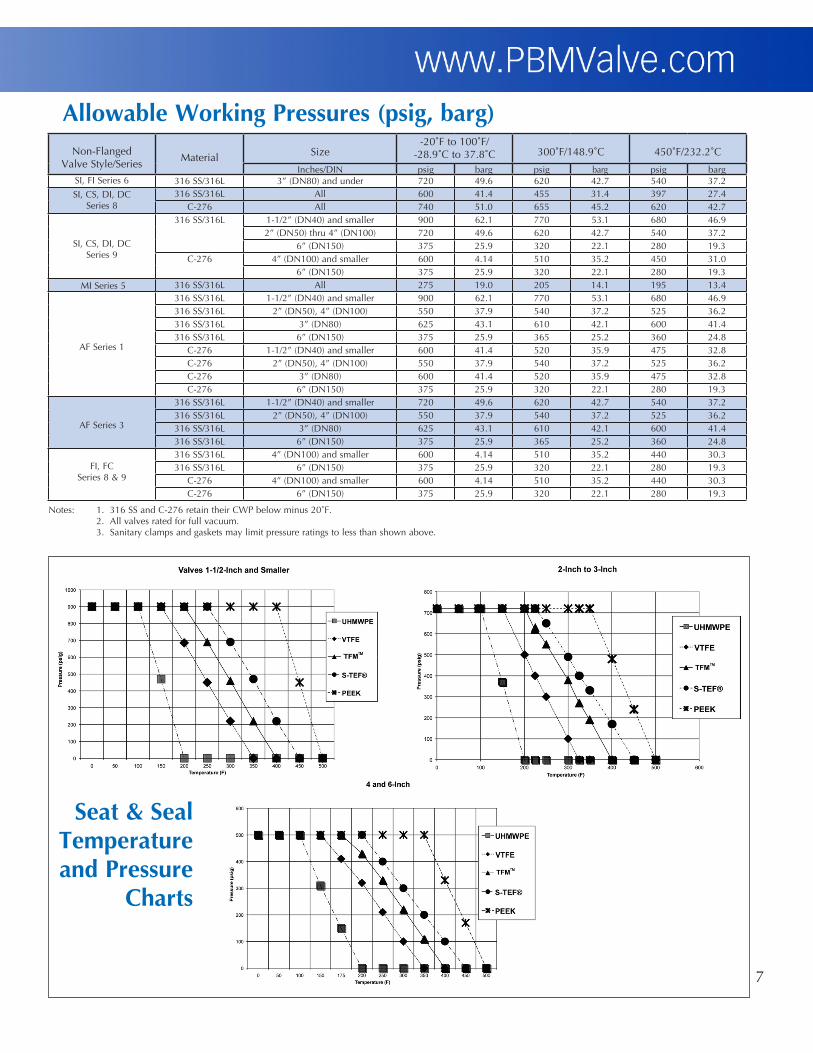
AllowableWorkingPressures(psig,barg)Non-Flanged
Valve Style/SeriesMaterial Size
-20˚F to 100˚F/-28.9˚C to 37.8˚C 300˚F/148.9˚C 450˚F/232.2˚C
Inches/DIN psig barg psig barg psig bargSI, FI Series 6 316 SS/316L 3” (DN80) and under 720 49.6 620 42.7 540 37.2SI, CS, DI, DC
Series 8316 SS/316L All 600 41.4 455 31.4 397 27.4
C-276 All 740 51.0 655 45.2 620 42.7
SI, CS, DI, DCSeries 9
316 SS/316L 1-1/2” (DN40) and smaller 900 62.1 770 53.1 680 46.92” (DN50) thru 4” (DN100) 720 49.6 620 42.7 540 37.2
6” (DN150) 375 25.9 320 22.1 280 19.3C-276 4” (DN100) and smaller 600 4.14 510 35.2 450 31.0
6” (DN150) 375 25.9 320 22.1 280 19.3 MI Series 5 316 SS/316L All 275 19.0 205 14.1 195 13.4
AF Series 1
316 SS/316L 1-1/2” (DN40) and smaller 900 62.1 770 53.1 680 46.9316 SS/316L 2” (DN50), 4” (DN100) 550 37.9 540 37.2 525 36.2316 SS/316L 3” (DN80) 625 43.1 610 42.1 600 41.4316 SS/316L 6” (DN150) 375 25.9 365 25.2 360 24.8
C-276 1-1/2” (DN40) and smaller 600 41.4 520 35.9 475 32.8C-276 2” (DN50), 4” (DN100) 550 37.9 540 37.2 525 36.2C-276 3” (DN80) 600 41.4 520 35.9 475 32.8C-276 6” (DN150) 375 25.9 320 22.1 280 19.3
AF Series 3
316 SS/316L 1-1/2” (DN40) and smaller 720 49.6 620 42.7 540 37.2316 SS/316L 2” (DN50), 4” (DN100) 550 37.9 540 37.2 525 36.2316 SS/316L 3” (DN80) 625 43.1 610 42.1 600 41.4316 SS/316L 6” (DN150) 375 25.9 365 25.2 360 24.8
FI, FCSeries 8 & 9
316 SS/316L 4” (DN100) and smaller 600 4.14 510 35.2 440 30.3316 SS/316L 6” (DN150) 375 25.9 320 22.1 280 19.3
C-276 4” (DN100) and smaller 600 4.14 510 35.2 440 30.3C-276 6” (DN150) 375 25.9 320 22.1 280 19.3
Notes: 1. 316 SS and C-276 retain their CWP below minus 20˚F. 2. All valves rated for full vacuum. 3. Sanitary clamps and gaskets may limit pressure ratings to less than shown above.
Seat&SealTemperatureandPressure
Charts
8
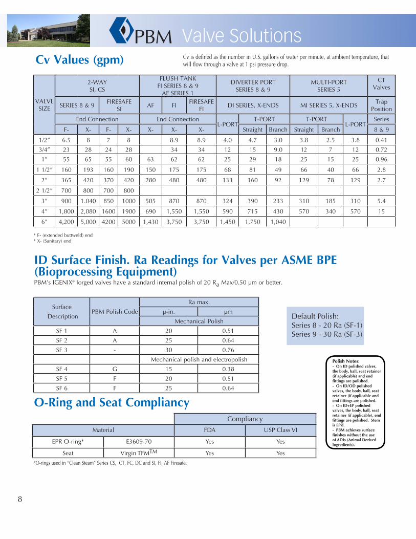
CvValues(gpm)
VALVESIZE
2-WAY SI, CS
FLUSH TANK FI SERIES 8 & 9
AF SERIES 1
DIVERTER PORTSERIES 8 & 9
MULTI-PORTSERIES 5
CTValves
SERIES 8 & 9FIRESAFE
SI AF FI
FIRESAFEFI
DI SERIES, X-ENDS MI SERIES 5, X-ENDSTrap
Position
End Connection End ConnectionL-PORT
T-PORT T-PORTL-PORT
Series
F- X- F- X- X- X- X- Straight Branch Straight Branch 8 & 9
1/2” 6.5 8 7 8 8.9 8.9 4.0 4.7 3.0 3.8 2.5 3.8 0.41
3/4” 23 28 24 28 34 34 12 15 9.0 12 7 12 0.72
1” 55 65 55 60 63 62 62 25 29 18 25 15 25 0.96
1 1/2” 160 193 160 190 150 175 175 68 81 49 66 40 66 2.8
2” 365 420 370 420 280 480 480 133 160 92 129 78 129 2.7
2 1/2” 700 800 700 800
3” 900 1.040 850 1000 505 870 870 324 390 233 310 185 310 5.4
4” 1,800 2,080 1600 1900 690 1,550 1,550 590 715 430 570 340 570 15
6” 4,200 5,000 4200 5000 1,430 3,750 3,750 1,450 1,750 1,040
* F- (extended buttweld) end* X- (Sanitary) end
IDSurfaceFinish.RaReadingsforValvesperASMEBPE(BioprocessingEquipment)PBM’s IGENIX® forged valves have a standard internal polish of 20 Ra Max/0.50 µm or better.
O-RingandSeatCompliancy
*O-rings used in “Clean Steam” Series CS, CT, FC, DC and SI, FI, AF Firesafe.
Surface
DescriptionPBM Polish Code
Ra max.
µ-in. µm
Mechanical Polish
SF 1 A 20 0.51
SF 2 A 25 0.64
SF 3 - 30 0.76
Mechanical polish and electropolish
SF 4 G 15 0.38
SF 5 F 20 0.51
SF 6 F 25 0.64
Default Polish:Series 8 - 20 Ra (SF-1)Series 9 - 30 Ra (SF-3)
Compliancy
Material FDA USP Class VI
EPR O-ring* E3609-70 Yes Yes
Seat Virgin TFMTM Yes Yes
Cv is defined as the number in U.S. gallons of water per minute, at ambient temperature, that will flow through a valve at 1 psi pressure drop.
PolishNotes:-OnIDpolishedvalves,thebody,ball,seatretainer(ifapplicable)andendfittingsarepolished.-OnID/ODpolishedvalves,thebody,ball,seatretainer(ifapplicableandendfittingsarepolished.-OnID+EPpolishedvalves,thebody,ball,seatretainer(ifapplicable),endfittingsarepolished.StemisEP’d.-PBMachievessurfacefinisheswithouttheuseofADIs(AnimalDerivedIngredients).

9
StemTorque
ValveStyle/Series
Valve Size(in.)
As builtTorque
TFMTM and VTFE Seats - Differential Pressure across Seats
0psig
0barg
100psig
6.9barg
200psig
13.8barg
300psig
20.7barg
400psig
27.6barg
500psig
34.5barg
600psig
41.4barg
700psig
48.3barg
in.-lb. N-m in.-lb. N-m in.-lb. N-m in.-lb. N-m in.-lb. N-m in.-lb. N-m in.-lb. N-m in.-lb. N-m in.-lb. N-m
Fire-safe
Series 6
1/4, 1/2 32 3.6 64 7.2 64 7.2 64 7.2 64 7.2 64 7.2 64 7.2 64 7.2 64 7.2
3/4 40 4.5 80 9.0 80 9.0 80 9.0 80 9.0 80 9.0 96 10.8 112 10.8 128 12.7
1 58 6.6 116 13.1 116 13.1 116 13.1 150 16.9 185 20.9 220 24.9 trun.
1-1/2 154 17.4 308 34.8 308 34.8 440 49.7 580 65.5 715 80.8 trun. trun.
2 182 20.6 364 41.1 364 41.1 635 71.7 910 102.8 1,180 133.3 trun. trun.
2-1/2 288 32.5 576 65.1 576 65.1 1,200 135.6 1,600 180.8 trun.
3 430 48.6 860 97.2 860 97.2 1,560 176.3 trun. trun.
4 787 88.9 1,570 177.4 1,570 177.4 2,650 299.4 trun. trun.
6 1,920 217.0 3,840 433.9 7,100 802.3 Use trunnion above 75 psig.
All Series 8 & 92-Way
and3-Way
1/2 25 2.8 50 5.7 50 5.7 50 5.7 50 5.7 50 5.7 50 5.7 50 5.7 50 5.7
3/4 30 3.4 60 6.8 60 6.8 60 6.8 60 6.8 60 6.8 60 6.8 60 6.8 80 9.0
1 50 5.7 100 11.3 100 11.3 100 11.3 130 14.7 160 18.1 220 24.9 trun. trun.
1-1/2 132 14.9 264 29.8 264 29.8 375 42.4 500 56.5 600 67.8 trun. trun.
2 182 20.6 364 41.10 364 41.1 635 71.8 910 102.8 1,180 133.3 trun. trun.
2-1/2 288 32.5 576 65.1 576 65.1 1,200 136 1,600 181 trun trun.
3 430 49 860 97.2 860 97.2 1,560 176 trun. trun.
4 672 76 1,340 151 1,340 151 2,250 254 trun. trun.
6 1,920 217 3,840 434 7,100 802 Use trunnion above 75 psig.
AFSeries 1
and Series 3
1 58 6.6 116 13.1 116 13.1 116 13.1 150 17.0 185 20.9 220 24.9 255 28.8 288 32.5
1-1/2 132 14.9 264 29.8 264 29.8 375 42.4 500 56.5 600 67.8 725 81.9 850 96.1 950 107
2 154 17.4 308 34.8 308 34.8 440 49.7 580 65.5 715 80.8 850 96.1
3 336 38.0 675 76.3 675 76.3 1,400 158 1,900 215 2,400 271 2,900 328 3,400 3844 432 49 860 97.2 860 97.2 1,560 176 2,050 232 2,540 287 3,030 3426 1,056 119 2,100 237 3,950 446
ValveSeries
SizeAs builtTorque
0psig
0barg
100psig
6.9barg
200psig
13.8barg
275psig
19.0barg
MI Series
5
1/2 67 7.6 135 9.3 142 9.8 149 10.3 154 10.63/4 80 9.0 160 11.0 167 11.5 174 12.0 182 12.5
1 154 17.4 307 21.2 322 22.2 337 23.2 358 24.71-1/2 313 35.4 627 43.2 670 46.2 759 52.3 843 58.1
2 491 55.5 981 67.6 1,037 71.5 1,238 85.4 1,388 95.73 840 95.0 1,679 115.8 2,084 143.7 2,761 190.4 3,268 225.3
4 1539 173.9 3,077 212.2 4,114 283.7 5,580 384.7 6,679 460.5
Notes: 1. For valves with UHMWPE seats, multiply the above values by 1.25
2. For valves which have S-TEF® or Kynar® seats, multiply the above values by 1.56.
3. For valves with PEEK® seats, multiply the above values by 1.7. 4. Where trunnion is indicated, PBM recommends trunnion mounting the ball to avoid excessive seat loads and stem torques. 5. To convert in-lbs. torques to N-m, multiply by 0.113.

10
Testing Optionsn Cryogenic n V-Balls for Flow Controln Manual Spring Return Handles n Internal & External Groundingn LOX (Cleaned for Oxygen Service) n Mechanical & Electro-Polishingn Body Cavity Fillers n Direct Mount Actuationn Steam Seats (Encapsulated) n Positionersn Purge Ports (SIP/CIP) n Fieldbus, AS-i, DeviceNetn Fire Rated, API 607 n Ball Flats and Purge Holesn Dribble Control Units n Locking Handlen High Alloys n Extended Locking Handlen Fabflex® Manifolds n Cylindrical Radius Weld Padsn Self Cleaning Flushable Ball
n Vacuum Testing*n Cycle Testingn Shock and Vibrationn Seismicn Hydrostaticn Material Test Reports
- Physical testing- Chemical testing
SteamValves
*PBM valves are ideally suited for vacuum service. For valves intended for vacuum service, PBM offers optional helium leakage test of the seats and shell. Also, the seats of the valve are helium leakage tested. PBM valves will meet a leakage rate of 1 x 10⁻⁶ std. cc/sec. helium leakage for both tests.

11
Options
DirectMountActuation
CavityFillers
CylindricalRadiusPad
PurgePorts,MilledFlatsandPurgeHoles
LockingHandle

12
FORGED VALVESSI-SERIES 8 (1/2” through 4”, DIN 11850 DN 8 through DN 100, ISO 1127 DN 8 through DN 80) PBM’s Forged IGENIX® Sanitary Series 8, “True Bore®” ball valve with port through ball, seats, and end fittings same as ID of tubing. Forged 316L stainless steel body and end fittings per ASTM A182F316L / DIN 1.4404, wrought or forged 316L ball and stem, less than 1% ferrite, three piece swing-out valve design. Seats and seals shall be white TFM™. Seats shall provide both upstream and downstream bubble-tight seal and be adjustable for inline wear. Stem packing shall be live loaded white TFM™ and S-TEF® material. End fittings shall match to tubing connections. Orbital weld end fittings should have wall thickness to match connecting tubing and have a controlled sulfur content of 0.005% through 0.017%. Valves shall not require disassembly for welding. Body bolts and nuts shall be 18-8 stainless steel. Interior surfaces shall be 20 RA or better with optional electropolish and finer mechanical finishes. Valve shall have integral mounting pad to allow adaptation to ISO 5211 for direct mount automation. All materials are FDA and USP23 Class VI compliant. Maximum working pressure to be 600 PSIG, but is limited based on valve size, valve material and end fitting type. Valves are full vacuum. To add automation and controls, see section “Automation and controls”.PBM Model number SI (material)(size)8(end connection); CS-SERIES 8 (1/2” through 4”, DIN 11850 DN 8 through DN 100, ISO 1127 DN 8 through DN 80) PBM’s IGENIX® Clean Steam Series 8. Same Specification as SI-Series 8 above. Add text “Seats and seals shall be white TFM™ with FDA approved EPR O-ring energizer. Seats shall have stainless steel encapsulation on ID. Body seal shall be FDA approved EPR o-rings with white TFM™ back up seal. Optional 300 Series stainless steel stem extension with locking lever handle for thick installation.PBM Model number CS (material)(size)8(end connection); Trap valve model number CT (material)(size)8(end connection)
CAST VALVESSI-SERIES 9 (1/2” through 6”, DIN 11850 DN 8 through DN 150, ISO 1127 DN 8 through DN 100) PBM’s IGENIX® Sanitary Series 9 “True Bore®” ball valve with port through ball, seats, and end fittings same as ID of tubing. Type (316 L stainless steel with low controlled ferrite, Hastelloy® C-276 or C22®, or other) body, ball, stem, and end fittings, three piece swing-out valve design. Seats and seals shall be combined “cartridge” and be white TFM™. Seats shall provide both upstream and downstream bubble-tight seal and be adjustable for inline wear. All materials are FDA and USP23 Class VI compliant. Stem packing shall be live loaded white TFM™ or S-TEF® material. End fittings shall match to tubing connections. Orbital weld end fittings should have wall thickness to match connecting tubing and have a controlled sulfur content of .005% through .017%. Valves shall not require disassembly for welding. Body bolts and nuts shall be 18-8 stainless steel. I.D. and O.D. surface finish shall be the same as specified for tubing. Maximum working pressure to be 900 PSIG, but is limited based on valve size, valve material and end fitting type. Valves are full vacuum. Valves shall be non-fire rated design unless otherwise specified. To add automation and controls, see section “Automation and controls”.PBM Model number SI (material)(size)9(end connection)
CS-SERIES 9 (1/2” through 6”): PBM’s IGENIX® Clean Steam Series 9, Same specification as SI (cast) above. Add text “Seats shall be white TFM™ with FDA approved EPR O-ring energizer. Seats shall have stainless steel encapsulation on ID. Optional 300 Series s/s stem extensions for thick insulation.PBM Model number CS (material)(size)9(end connection)
CT-SERIES 8 (forged) OR SERIES 9 (cast): PBM’s IGENIX® Clean Steam Series 8 or 9. Same specification as CS forged or cast above. Add text. ”Valve shall have a dual chamber seat design to allow for a 1/2” Tri-Clamp® steam drain purge port positioned in the valve body to facilitate drainage of the body cavity to the trap. Ball shall have 2 steam purge holes to allow steam condensate to flow past seats in closed position to trap. Stem packing shall be live loaded white TFM™ and S-TEF®. Provide a 90˚ 2-position or 180˚ 3-position stainless steel handle with blue vinyl grip for closed/open, and/or trap isolated valve positions. A locking handle position mechanism shall be available if required. PBM Model number CT (material)(size)8 or 9(end connection)
FI & AF SERIESFI-SERIES 9 (1/2” through 6”): Flush tank bottom ball valve: PBM’s IGENIX® Sanitary Series 9 Flush Tank Ball Valve. “True Bore®” flush bottom tank ball valve with port through ball, seats, weld pad, and end fitting same as ID of tubing. Type 316L stainless steel with low controlled ferrite, Hastelloy® C-276, Carbon Steel, Hastelloy® C-22®, or other materials for body, ball, stem, weld pad, and end fitting, three piece swing-out valve design. Seats and seals shall be white TFM™. Seats shall provide both upstream and downstream bubble-tight seal and be adjustable for inline wear. Stem packing shall be live loaded white TFM™ and/or S-TEF® material. End fitting shall match to tubing connections. Orbital weld end fittings should have wall thickness to match connecting tubing and have a controlled sulfur content of .005% through .017%. Valves shall not require disassembly for welding. Body bolts and nuts shall be 18-8 stainless steel. I.D. and O.D. surface finish shall be the same as specified for tubing. Maximum working pressure to be 600 PSIG, but is limited based on valve size, valve material and end fitting type. Valves are full vacuum.PBM Model number FI(material)-(size)9(end connection)
WrittenSpecifications
13
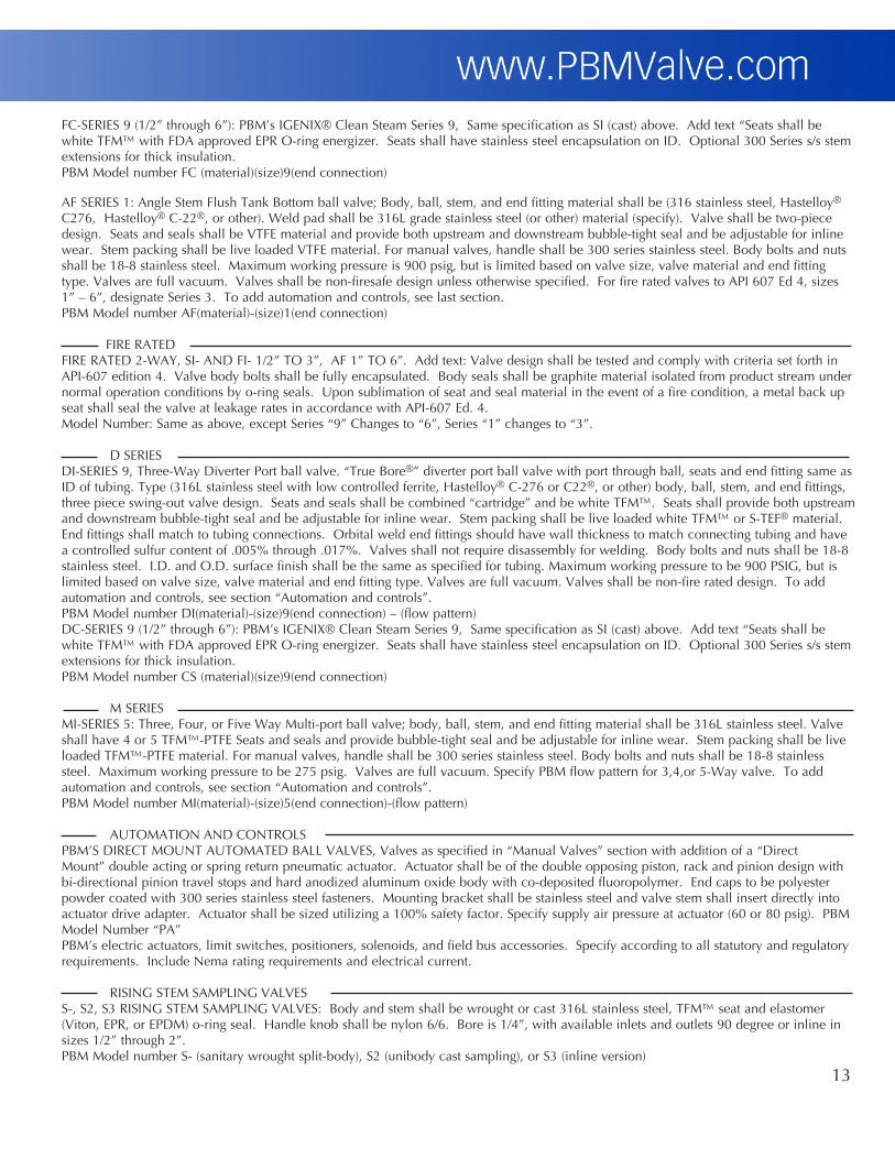
FC-SERIES 9 (1/2” through 6”): PBM’s IGENIX® Clean Steam Series 9, Same specification as SI (cast) above. Add text “Seats shall be white TFM™ with FDA approved EPR O-ring energizer. Seats shall have stainless steel encapsulation on ID. Optional 300 Series s/s stem extensions for thick insulation.PBM Model number FC (material)(size)9(end connection)
AF SERIES 1: Angle Stem Flush Tank Bottom ball valve; Body, ball, stem, and end fitting material shall be (316 stainless steel, Hastelloy®
C276, Hastelloy® C-22®, or other). Weld pad shall be 316L grade stainless steel (or other) material (specify). Valve shall be two-piece design. Seats and seals shall be VTFE material and provide both upstream and downstream bubble-tight seal and be adjustable for inline wear. Stem packing shall be live loaded VTFE material. For manual valves, handle shall be 300 series stainless steel. Body bolts and nuts shall be 18-8 stainless steel. Maximum working pressure is 900 psig, but is limited based on valve size, valve material and end fitting type. Valves are full vacuum. Valves shall be non-firesafe design unless otherwise specified. For fire rated valves to API 607 Ed 4, sizes 1” – 6”, designate Series 3. To add automation and controls, see last section. PBM Model number AF(material)-(size)1(end connection)
FIRE RATED FIRE RATED 2-WAY, SI- AND FI- 1/2” TO 3”, AF 1” TO 6”. Add text: Valve design shall be tested and comply with criteria set forth in API-607 edition 4. Valve body bolts shall be fully encapsulated. Body seals shall be graphite material isolated from product stream under normal operation conditions by o-ring seals. Upon sublimation of seat and seal material in the event of a fire condition, a metal back up seat shall seal the valve at leakage rates in accordance with API-607 Ed. 4.Model Number: Same as above, except Series “9” Changes to “6”, Series “1” changes to “3”.
D SERIESDI-SERIES 9, Three-Way Diverter Port ball valve. “True Bore®” diverter port ball valve with port through ball, seats and end fitting same as ID of tubing. Type (316L stainless steel with low controlled ferrite, Hastelloy® C-276 or C22®, or other) body, ball, stem, and end fittings, three piece swing-out valve design. Seats and seals shall be combined “cartridge” and be white TFM™. Seats shall provide both upstream and downstream bubble-tight seal and be adjustable for inline wear. Stem packing shall be live loaded white TFM™ or S-TEF® material. End fittings shall match to tubing connections. Orbital weld end fittings should have wall thickness to match connecting tubing and have a controlled sulfur content of .005% through .017%. Valves shall not require disassembly for welding. Body bolts and nuts shall be 18-8 stainless steel. I.D. and O.D. surface finish shall be the same as specified for tubing. Maximum working pressure to be 900 PSIG, but is limited based on valve size, valve material and end fitting type. Valves are full vacuum. Valves shall be non-fire rated design. To add automation and controls, see section “Automation and controls”.PBM Model number DI(material)-(size)9(end connection) – (flow pattern)DC-SERIES 9 (1/2” through 6”): PBM’s IGENIX® Clean Steam Series 9, Same specification as SI (cast) above. Add text “Seats shall be white TFM™ with FDA approved EPR O-ring energizer. Seats shall have stainless steel encapsulation on ID. Optional 300 Series s/s stem extensions for thick insulation.PBM Model number CS (material)(size)9(end connection)
M SERIESMI-SERIES 5: Three, Four, or Five Way Multi-port ball valve; body, ball, stem, and end fitting material shall be 316L stainless steel. Valve shall have 4 or 5 TFM™-PTFE Seats and seals and provide bubble-tight seal and be adjustable for inline wear. Stem packing shall be live loaded TFM™-PTFE material. For manual valves, handle shall be 300 series stainless steel. Body bolts and nuts shall be 18-8 stainless steel. Maximum working pressure to be 275 psig. Valves are full vacuum. Specify PBM flow pattern for 3,4,or 5-Way valve. To add automation and controls, see section “Automation and controls”. PBM Model number MI(material)-(size)5(end connection)-(flow pattern)
AUTOMATION AND CONTROLSPBM’S DIRECT MOUNT AUTOMATED BALL VALVES, Valves as specified in “Manual Valves” section with addition of a “Direct Mount” double acting or spring return pneumatic actuator. Actuator shall be of the double opposing piston, rack and pinion design with bi-directional pinion travel stops and hard anodized aluminum oxide body with co-deposited fluoropolymer. End caps to be polyester powder coated with 300 series stainless steel fasteners. Mounting bracket shall be stainless steel and valve stem shall insert directly into actuator drive adapter. Actuator shall be sized utilizing a 100% safety factor. Specify supply air pressure at actuator (60 or 80 psig). PBM Model Number “PA” PBM’s electric actuators, limit switches, positioners, solenoids, and field bus accessories. Specify according to all statutory and regulatory requirements. Include Nema rating requirements and electrical current.
RISING STEM SAMPLING VALVESS-, S2, S3 RISING STEM SAMPLING VALVES: Body and stem shall be wrought or cast 316L stainless steel, TFM™ seat and elastomer (Viton, EPR, or EPDM) o-ring seal. Handle knob shall be nylon 6/6. Bore is 1/4”, with available inlets and outlets 90 degree or inline in sizes 1/2” through 2”. PBM Model number S- (sanitary wrought split-body), S2 (unibody cast sampling), or S3 (inline version)
14
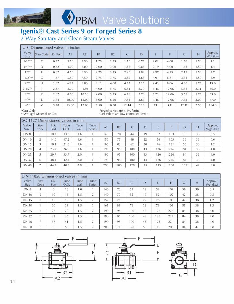
Igenix®CastSeries9orForgedSeries82-Way Sanitary and Clean Steam Valves
U.S. Dimensioned valves in inchesValveSize
Size Code I.D. Port A1 A2 B1 B2 C D E F G HApprox.Wgt (lbs)
1/2”** C 0.37 3.50 5.50 1.75 2.75 1.70 0.75 2.03 4.00 1.50 1.50 1.1
3/4”** D 0.62 4.00 6.00 2.00 3.00 1.86 0.85 2.19 4.00 1.68 1.50 1.4
1”** E 0.87 4.50 6.50 2.25 3.25 2.40 1.09 2.97 4.15 2.18 1.50 2.7
1-1/2”** G 1.37 5.50 7.50 2.75 3.75 3.89 1.68 4.91 8.81 3.31 1.50 8.9
2”** H 1.87 6.25 8.00 3.12 4.00 4.67 2.15 4.41 8.06 4.30 1.75 15.0
2-1/2”* J 2.37 8.00 11.50 4.00 5.75 6.51 2.79 6.46 12.06 5.58 2.31 36.0
3”** K 2.87 8.00 10.50 4.00 5.25 6.76 2.78 6.71 12.06 5.58 1.75 33.0
4”** L 3.84 10.00 13.00 5.00 6.50 7.53 3.66 7.48 12.06 7.33 2.00 67.0
6”* M 5.78 13.00 17.00 6.50 8.50 12.14 6.18 CF CF 12.37 2.50 164.0
*Cast Only Forged valves are < 1% ferrite.**Wrought Material or Cast Cast valves are low controlled ferrite
A1 B1 G
F
E
D
C C
F
E
B2 A2
ISO 1127 Dimensioned valves in mmValveSize
Size Code
I.D.Port
TubeO.D.
Tubewall
TubeSeries
A2 B2 C D E F G HApprox.
Wgt. (kg.)
DN 8 1 10.3 13.5 1.6 1 140 70 44 19 52 103 38 38 0.5
DN 10 2 14.0 17.2 1.6 1 150 75 48 22 56 103 38 38 0.6
DN 15 3 18.1 21.3 1.6 1 165 83 62 28 76 131 55 38 1.2
DN 20 4 23.7 26.9 1.6 1 190 95 100 43 126 226 84 38 4.0
DN 25 5 29.7 33.7 2.0 1 190 95 100 43 126 226 84 38 4.0
DN 32 6 38.4 42.4 2.0 1 190 95 100 43 126 226 84 38 4.0
DN 40 7 44.3 48.3 2.0 1 200 100 120 55 113 208 109 42 6.8
DIN 11850 Dimensioned valves in mmValveSize
Size Code
I.D.Port
TubeO.D.
Tubewall
TubeSeries
A2 B2 C D E F G HApprox.Wgt (kg.)
DN 8 1 8 10 1.0 1 140 70 52 19 52 102 38 38 0.5
DN 10 2 10 13 1.5 2 140 70 52 19 52 102 42 38 0.5
DN 15 3 16 19 1.5 2 152 76 56 22 76 105 42 38 1.2
DN 20 4 20 23 1.5 2 165 83 76 28 76 105 55 38 1.2
DN 25 5 26 29 1.5 2 190 95 100 43 125 224 84 38 4.0
DN 32 6 32 35 1.5 2 190 95 100 43 125 224 84 38 4.0
DN 40 7 38 41 1.5 2 190 95 100 43 125 224 84 38 4.0
DN 50 8 50 53 1.5 2 200 100 120 55 119 205 109 42 6.8

15
Igenix®CastSeries9orForgedSeries8ExtendedLockingLeverHandleExtended Locking Lever Handle
LockingHandle
Valve Size A B C EUS DN ID ISO inches mm inches mm inches mm inches mm1/2” 8, 10 8 5.09 129 4.00 102 2.50 64 0.31 83/4” - 10 5.09 129 4.14 105 2.50 64 0.31 81” 15,20 15 5.09 129 5.44 138 3.50 89 0.31 8
1-1/2” 25,32,40 20,25,32 8.00 203 7.46 189 3.75 95 0.38 102” 50 40 8.00 203 7.74 197 4.30 109 0.38 10
2-1/2” - - 12.10 307 11.36 289 5.58 142 0.38 103” - - 12.40 315 11.61 295 5.58 142 0.38 104” - - 12.40 315 12.38 314 7.33 186 0.38 10
Valve Size A B C
US DIN ISO inches mm inches mm inches mm1/2” 8, 10 8 4.00 102 2.03 52 1.55 393/4” - 10 4.00 102 2.19 56 1.55 391” 15,20 15 5.10 130 2.97 75 1.64 42
1-1/2” 25,32,40 20,25,32 8.80 224 4.91 125 2.57 652” 50 40 8.10 206 4.41 112 2.57 65
2-1/2” - - 12.40 315 6.46 164 3.84 983” - - 12.40 315 6.75 171 3.84 984” - - 12.40 315 7.75 197 3.84 98
A
B
A
B
C
E
Manual Valves with Tubing Ends (inches)
ValveSize
TubeOD
Insulation max with
no extension
Insulation max withextension
1/2” 0.500 0.76 2.68
3/4” 0.750 0.79 2.72
1” 1.000 1.45 3.88
1-1/2” 1.500 3.10 5.57
2” 2.000 2.31 5.60
2-1/2” 2.500 4.00 8.88
3” 3.000 4.08 8.88
4” 4.000 4.35 9.12 Maximum insulation dimensions shown allow for 3/4” of clearance between outside of insulation and bottom of handle.
C

16
Igenix®CastSeries9orForgedSeries8Actuated
Valve Size Model NumberPAVCL
A B C D E F (Flush Tank only)
US DIN ISO inches mm inches mm inches mm inches mm inches inches mm
1/2” 8, 10 8 453S--0052 5.55 141 2.80 71 5.45 138 1.61 41 1/8 NPT -0.13 -3
3/4” - 10 453S--0052 5.55 141 2.80 71 5.59 142 1.61 41 1/8 NPT 0.00 0
1” 15,20 15 453S--0063 6.46 164 3.17 81 6.51 165 1.77 45 1/8 NPT 0.13 3
1-1/2” 25,32,40 20,25,32 453S--0085 9.47 241 4.17 106 9.65 194 2.30 58 1/8 NPT 0.36 9
2” 50 40 453S--0100 10.83 275 4.84 123 10.45 265 2.68 68 1/4 NPT 0.41 10
2-1/2” - - 453S--0115 13.11 333 5.39 137 13.48 342 2.87 73 1/4 NPT 0.57 14
3” - - 453S--0125 14.65 372 5.83 148 14.21 340 3.15 80 1/4 NPT 2.01 51
4” - - 453S--0140 17.13 435 6.46 164 15.86 382 3.44 87 1/4 NPT 1.60 41
6” - - 453S--0200 22.78 579 8.54 218 23.02 546 4.29 109 1/4 NPT 2.00 51
Valve Size Model NumberPAVCL
A B C D E F (Flush Tank only)
US Din ISO inches mm inches mm inches mm Inch mm inches inches mm
1/2” 8, 10 8 253S--0063 5.55 141 3.17 81 5.90 150 1.77 45 1/8 NPT -0.13 -3
3/4” - 10 253S--0063 6.46 164 3.17 81 6.04 153 1.77 45 1/8 NPT -0.21 -5
1” 15,20 15 253S--0075 8.27 210 3.72 94 7.22 183 2.07 53 1/8 NPT -0.12 -3
1-1/2” 25,32,40 20,25,32 253S--0100 10.83 275 4.84 123 9.65 245 2.68 68 1/4 NPT 0.07 2
2” 50 40 253S--0115 13.11 333 5.39 137 11.80 300 2.87 73 1/4 NPT 0.05 1
2-1/2” - - 253S--0125 14.65 372 5.83 148 13.96 355 3.15 80 1/4 NPT 0.41 10
3” - - 253S--0140 17.13 435 6.46 164 15.10 384 3.44 87 1/4 NPT 1.27 32
4” - - 253S--0160 19.69 500 7.32 186 16.80 427 3.90 99 1/4 NPT 1.18 30
6” - - 253S--0270 22.64 672 11.42 290 27.78 706 5.71 145 1/4 NPT 2.00 51
Spring Return SR Series 80 PSI/5.5 barg Supply Air, TFMTM Seats
Spring Return SR Series 60 psig/4.1 barg Supply Air, TFMTM Seats
A B
E
D
C
E
SI, CS shown

17
Valve Size Model NumberPAVCL
A B C D E F (Flush Tank only)
US Din ISO PAVBL mm inches mm inches mm inches mm inches inches mm
1/2” 8, 10 8 453D--0052 5.55 141 2.80 71 5.45 138 1.61 41 1/8 NPT -0.13 -3
3/4” - 10 453D--0052 5.55 141 2.80 71 5.59 142 1.61 41 1/8 NPT 0.00 0
1” 15,20 15 453D--0052 5.55 141 2.80 71 6.06 154 1.61 41 1/8 NPT 0.34 9
1-1/2” 25,32,40 20,25,32 453D--0063 8.27 210 3.72 94 9.10 231 2.07 53 1/8 NPT 0.58 15
2” 50 40 453D--0075 8.27 210 3.72 94 9.39 239 2.07 53 1/8 NPT 0.92 23
3” - - 453D--0115 13.11 333 5.39 137 13.73 349 2.87 73 1/4 NPT 2.17 55
4” - - 453D--0160 13.11 333 5.39 137 14.51 369 2.87 73 1/4 NPT 2.08 53
6” - - 453D--0200 22.78 579 8.54 217 23.02 585 4.29 109 1/4 NPT 2.00 51
Valve Size Model NumberPAVCL
A B C D E F (Flush Tank only)
US Din ISO inches mm inches mm inches mm inches mm inches inches mm
1/2” 8, 10 8 253D--0052 5.55 141 2.80 71 5.45 138 1.61 41 1/8 NPT -0.13 -3
3/4” - 10 253D--0052 5.55 141 2.80 71 5.59 142 1.61 41 1/8 NPT 0.00 0
1” 15,20 15 253D--0052 5.55 141 2.80 71 6.00 152 1.61 41 1/8 NPT 0.34 9
1-1/2” 25,32,40 20,25,32 253D--0075 8.27 210 3.72 94 9.10 231 2.07 53 1/8 NPT 0.58 15
2” 50 40 253D--0075 8.27 210 3.72 94 9.39 239 2.07 53 1/8 NPT 0.92 23
3” - - 253D--0115 13.11 333 5.39 137 13.73 349 2.87 73 1/4 NPT 2.17 55
4” - - 253D--0160 13.11 333 5.39 137 14.51 369 2.87 73 1/4 NPT 2.08 53
6” - - 253D--0200 22.78 579 8.54 217 23.02 585 4.29 109 1/4 NPT 2.00 51
Double Acting DA Series 80 psig/5.5 barg Supply Air, TFMTM Seats
Double Acting DA Series 60 psig/4.1 barg Supply Air, TFMTM Seats
A
B
F
E
D
See Page 20 for “H” and “I”.
E C
I FI, FC shown
H

18
Igenix®FlushTankCastSeries9orForgedSeries8Valve Size
SizeCode
UnitsI.D. Port
A B C D E F G H IApprox. Weight
1/2”**DN 15
Cinches 0.37 2.83 1.75 1.70 0.75 2.05 4.00 1.50 0.30 2.75 1.6 lbs.
mm 9 72 44 43 19 52 102 38 8 70 .73 kg.
3/4”**DN 20
Dinches 0.62 3.16 2.00 1.86 0.85 2.23 4.00 1.68 0.30 3.00 2 lbs.
mm 16 80 51 47 22 57 102 43 8 76 .91 kg.
1”**DN 25
Einches 0.87 3.70 2.25 2.38 1.09 3.01 4.15 2.18 0.31 3.75 3.6 lbs.
mm 22 94 57 60 28 76 105 55 8 95 1.63 kg.
1-1/2”**DN 40
Ginches 1.37 4.98 2.75 3.89 1.68 5.07 8.81 3.31 0.68 5.50 12 lbs.
mm 35 126 70 99 43 129 224 84 17 140 5.44 kg.
2”**DN 50
Hinches 1.87 5.79 3.12 4.67 2.15 4.51 8.03 4.30 0.49 6.50 22 lbs.
mm 47 147 79 119 55 115 204 109 12 165 9.88 kg.
3”**DN 80
Kinches 2.87 7.52 4.00 6.76 2.77 6.76 12.06 5.54 0.85 9.00 33 lbs.
mm 73 191 102 172 70 172 306 141 22 229 15 kg.
4”**DN 100
Linches 3.84 9.59 5.00 7.53 3.66 7.53 12.06 7.33 1.18 11.50 94 lbs.
mm 98 244 127 191 93 191 306 186 30 292 42.64 kg.
6”*DN 150
Minches 5.78 12.78 6.50 12.14 6.18 N/A N/A 12.36 1.34 17.00 164 lbs.
mm 147 325 165 308 157 N/A N/A 314 34 432 74.39 kg.
*Cast Only**Wrought Material or Cast
A
B
C
F
E
D
H
I
G
19
PBM, Inc.1070 Sandy Hill RoadIrw
in Pa. 15642-9409
Phone: 724-863-0550 Fax: 724-864-9255
THIS D
RAWIN
G CO
NTA
INS CO
NFID
ENTIA
L INFO
RMATIO
N D
EEMED
BY ITS OW
NER,
PBM, IN
C. TO CO
NSTITU
TE TRAD
E SECRETS. THE D
RAWIN
G IS SU
BMITTED
FOR EVA
LUATIO
N PU
RPOSES O
NLY A
ND
MAY N
OT BE CO
PIED O
R SHO
WN
TO TH
IRDPA
RTIES EXCEPT WITH
THE PRIO
R WRITTEN
CON
SENT O
F PBM, IN
C. THIS
DRAW
ING
MU
ST BR RETURN
ED TO
PBM, IN
C. UPO
N ITS REQ
UEST.
PBM INC. SERIES "8" IGENIX "DI","DM"AND "DC" 3-WAY MANUAL BALL VALVES
WITH TT END CONNECTIONSINIT
DATE
DRGW
F8/22/03
SIZE
BFSCM
NUMBER
92021DW
G. NO.
SK-D221REV.
0CHK
APPSCALE:
N.T.S.W
EIGHT: N/ASHEET 1 of 1
REV.No.
REV.DATE
CHKBY
APPBY
REMARKS
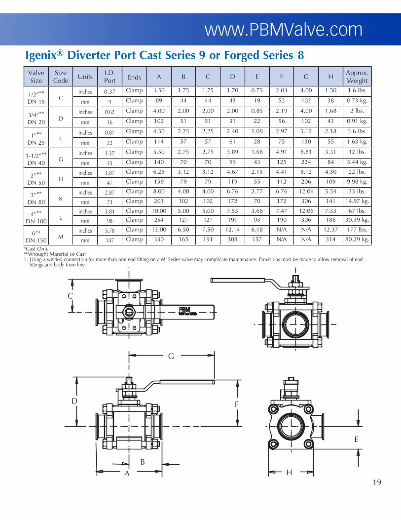
Valve Size
SizeCode
UnitsI.D. Port Ends A B C D E F G H
Approx. Weight
1/2”**DN 15
Cinches 0.37 Clamp 3.50 1.75 1.75 1.70 0.75 2.03 4.00 1.50 1.6 lbs.
mm 9 Clamp 89 44 44 43 19 52 102 38 0.73 kg.
3/4”**DN 20
Dinches 0.62 Clamp 4.00 2.00 2.00 2.00 0.85 2.19 4.00 1.68 2 lbs.
mm 16 Clamp 102 51 51 51 22 56 102 43 0.91 kg.
1”**DN 25
Einches 0.87 Clamp 4.50 2.25 2.25 2.40 1.09 2.97 5.12 2.18 3.6 lbs.
mm 22 Clamp 114 57 57 61 28 75 130 55 1.63 kg.
1-1/2”**DN 40
Ginches 1.37 Clamp 5.50 2.75 2.75 3.89 1.68 4.91 8.81 3.31 12 lbs.
mm 35 Clamp 140 70 70 99 43 125 224 84 5.44 kg.
2”**DN 50
Hinches 1.87 Clamp 6.25 3.12 3.12 4.67 2.15 4.41 8.12 4.30 22 lbs.
mm 47 Clamp 159 79 79 119 55 112 206 109 9.98 kg.
3”**DN 80
Kinches 2.87 Clamp 8.00 4.00 4.00 6.76 2.77 6.76 12.06 5.54 33 lbs.
mm 73 Clamp 203 102 102 172 70 172 306 141 14.97 kg.
4”**DN 100
Linches 3.84 Clamp 10.00 5.00 5.00 7.53 3.66 7.47 12.06 7.33 67 lbs.
mm 98 Clamp 254 127 127 191 93 190 306 186 30.39 kg.
6”*DN 150
Minches 5.78 Clamp 13.00 6.50 7.50 12.14 6.18 N/A N/A 12.37 177 lbs.
mm 147 Clamp 330 165 191 308 157 N/A N/A 314 80.29 kg.
Igenix®DiverterPortCastSeries9orForgedSeries8
*Cast Only**Wrought Material or Cast1. Using a welded connection for more than one end fitting on a MI Series valve may complicate maintenance. Provisions must be made to allow removal of end fittings and body from line.
A B
G
F
E
D
H
C
20
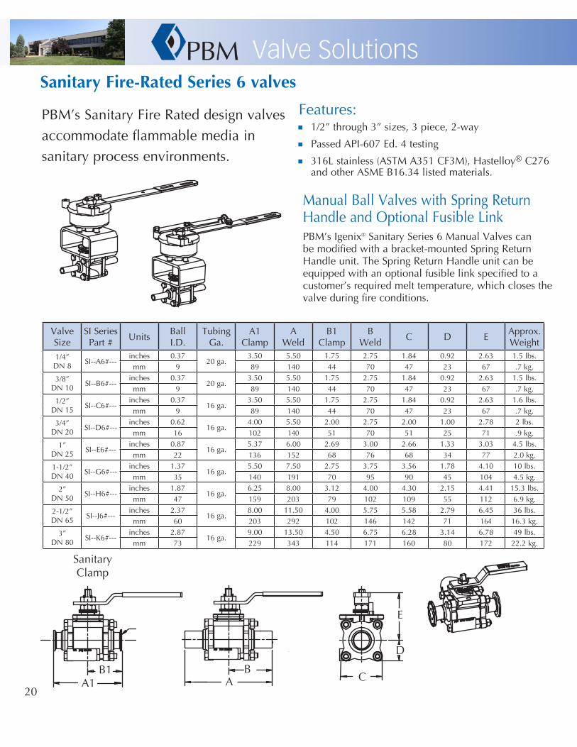
n 1/2” through 3” sizes, 3 piece, 2-way
n Passed API-607 Ed. 4 testing
n 316L stainless (ASTM A351 CF3M), Hastelloy® C276 and other ASME B16.34 listed materials.
PBM’s Sanitary Fire Rated design valves accommodate flammable media in sanitary process environments.
SanitaryFire-RatedSeries6valves
Manual Ball Valves with Spring Return Handle and Optional Fusible LinkPBM’s Igenix® Sanitary Series 6 Manual Valves can be modified with a bracket-mounted Spring Return Handle unit. The Spring Return Handle unit can be equipped with an optional fusible link specified to a customer’s required melt temperature, which closes the valve during fire conditions.
Series 6-SI-SRH
Series 6-SI-FLH
Features:
Valve Size
SI SeriesPart #
UnitsBallI.D.
TubingGa.
A1Clamp
AWeld
B1Clamp
BWeld
C D EApprox.Weight
1/4”DN 8
SI--A6#---inches 0.37
20 ga.3.50 5.50 1.75 2.75 1.84 0.92 2.63 1.5 lbs.
mm 9 89 140 44 70 47 23 67 .7 kg.
3/8”DN 10
SI--B6#---inches 0.37
20 ga.3.50 5.50 1.75 2.75 1.84 0.92 2.63 1.5 lbs.
mm 9 89 140 44 70 47 23 67 .7 kg.
1/2”DN 15
SI--C6#---inches 0.37
16 ga.3.50 5.50 1.75 2.75 1.84 0.92 2.63 1.6 lbs.
mm 9 89 140 44 70 47 23 67 .7 kg.
3/4”DN 20
SI--D6#---inches 0.62
16 ga.4.00 5.50 2.00 2.75 2.00 1.00 2.78 2 lbs.
mm 16 102 140 51 70 51 25 71 .9 kg.
1”DN 25
SI--E6#---inches 0.87
16 ga.5.37 6.00 2.69 3.00 2.66 1.33 3.03 4.5 lbs.
mm 22 136 152 68 76 68 34 77 2.0 kg.
1-1/2”DN 40
SI--G6#---inches 1.37
16 ga.5.50 7.50 2.75 3.75 3.56 1.78 4.10 10 lbs.
mm 35 140 191 70 95 90 45 104 4.5 kg.
2”DN 50
SI--H6#---inches 1.87
16 ga.6.25 8.00 3.12 4.00 4.30 2.15 4.41 15.3 lbs.
mm 47 159 203 79 102 109 55 112 6.9 kg.
2-1/2”DN 65
SI--J6#---inches 2.37
16 ga.8.00 11.50 4.00 5.75 5.58 2.79 6.45 36 lbs.
mm 60 203 292 102 146 142 71 164 16.3 kg.
3”DN 80
SI--K6#---inches 2.87
16 ga.9.00 13.50 4.50 6.75 6.28 3.14 6.78 49 lbs.
mm 73 229 343 114 171 160 80 172 22.2 kg.
AB
C
SanitaryClamp
E
D
A1 B1

21
AutomatedSI,FISeries6ValveswithDirectMountActuation
Valve SizeSI, FI
Valve NumberUnits
DOUBLE ACTING, TFMTM SEATS*
80 psig / 5.5 barg Supply Air 60 psig / 4.1 barg Supply Air
A B C D E A B C D E
1/2”DN15 * * --C6#---
inches 5.55 2.80 5.84 1.61 1/8 5.55 2.80 5.84 1.61 1/8
mm 141 71 148 41 141 71 146 41
3/4”DN 20 * * --D6#---
inches 5.55 2.80 5.99 1.61 1/8 5.55 2.80 5.99 1.61 1/8
mm 141 71 152 41 141 71 152 41
1”DN 25 * * --E6#---
inches 5.55 2.80 6.64 1.61 1/8 5.55 2.80 6.64 1.61 1/8
mm 141 71 169 41 141 71 169 41
1-1/2”DN 40 * * --G6#---
inches 6.46 3.17 8.39 1.77 1/8 8.27 3.72 9.10 2.07 1/8
mm 164 81 213 45 210 94 231 53
2”DN 50 * * --H6#---
inches 8.27 3.72 9.41 2.07 1/8 8.27 3.72 9.41 2.07 1/8
mm 210 94 239 53 210 94 239 53
2-1/2”DN 65 * * --J6#---
inches 13.11 5.39 13.48 2.87 1/4 13.11 5.39 13.48 2.87 1/4
mm 333 137 342 73 333 137 342 73
3”DN 80 * * --K6#---
inches 13.11 5.39 13.81 2.87 1/4 13.11 5.39 1381 2.87 1/4
mm 333 137 351 73 333 137 351 73
Valve SizeSI, FI
Valve NumberUnits
SPRING RETURN, TFMTM SEATS*80 psig / 5.5 barg Supply Air 60 psig / 4.1 barg Supply Air
A B C D E A B C D E1/2”
DN 15 * * --C6#---inches 5.55 2.80 5.84 1.61 1/8 6.46 3.17 627 1.77 1/8
mm 141 71 148 41 164 81 159 45
3/4”DN 20 * * --D6#---
inches 6.46 3.17 6.44 1.77 1/8 6.46 3.17 6.44 1.77 1/8mm 164 81 164 45 164 81 164 45
1”DN 25 * * --E6#---
inches 8.27 3.72 7.80 2.07 1/8 8.27 3.72 7.80 2.07 1/8mm 210 94 198 53 210 94 198 53
1-1/2”DN 40 * * --G6#---
inches 10.83 4.84 10.16 2.68 1/4 10.83 4.84 10.16 2.68 1/4mm 275 123 258 68 275 123 258 68
2”DN 50 * * --H6#---
inches 10.83 4.84 10.47 2.68 1/4 13.11 5.39 11.82 2.87 1/4mm 275 123 266 68 333 137 300 73
2-1/2”DN 65 * * --J6#---
inches 13.11 5.39 13.48 2.87 1/4 14.65 5.83 13.96 3.15 1/4mm 333 137 342 73 372 148 355 80
3”DN 80 * * --K6#---
inches 14.65 5.83 14.29 3.15 1/4 17.13 6.46 15.18 3.44 1/4
mm 372 148 363 80 435 164 386 87
*Consult factory for other seat materials.** True Bore® Valve Series SI, FI# End Connection type (See Order Codes)* * Operator Code (See Order Codes)
. .
.
.
SK-L015
..
A B
EFNPT
D
C
EFNPT

22
B C D G H I
Size Units Port
Face-to-Face CL to End
CL to Bottom Pad Diameter Pad ThicknessX-Clamp
X-Clamp
1”DN 25
inches 1.00 3.88 2.24 1.69 3.70 0.53mm 25 99 57 43 94 13
1-1/2”DN 40
inches 1.50 4.71 2.43 1.78 5.50 0.62mm 38 120 62 45 140 16
2”DN 50
inches 1.94 5.51 2.84 2.12 7.00 0.68mm 49 140 72 54 178 17
3”DN 80
inches 2.75 7.88 3.81 3.87 10.00 0.79mm 70 200 97 98 254 20
4”DN 100
inches 3.50 8.94 4.66 4.47 11.50 0.91mm 89 227 118 114 292 23
6”DN 150
inches 5.24 14.59 9.03 6.31 15.00 1.04mm 133 371 229 160 381 26
AF-Series1&3
1” & 1-1/2” = 10˚2”, 3”, 4”, & 6” = 15˚
Sanitary Clamp End Connection
B
C
H
I D
G
< degrees
Fire test qualified through 6”.
23
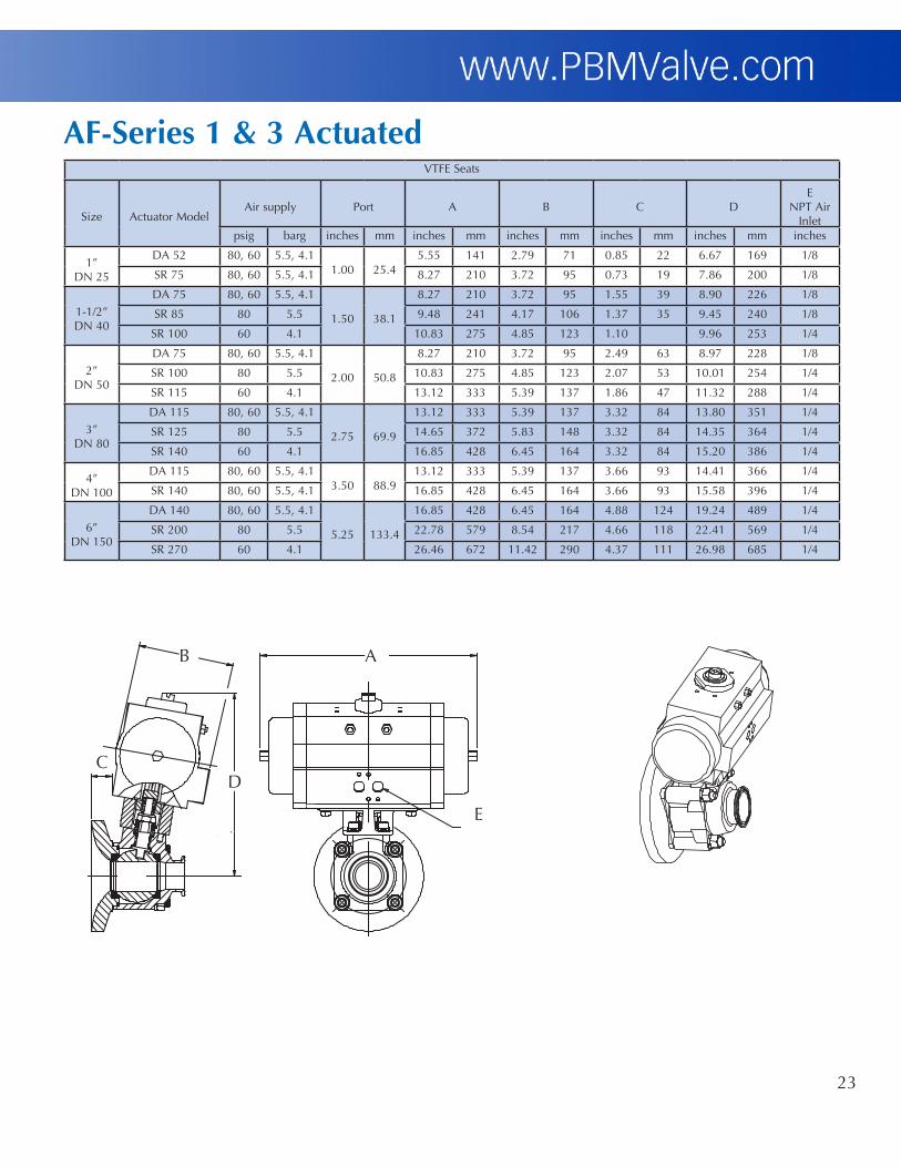
AF-Series1&3Actuated
AB
E
D C
VTFE Seats
Size Actuator ModelAir supply Port A B C D
E NPT Air
Inletpsig barg inches mm inches mm inches mm inches mm inches mm inches
1”DN 25
DA 52 80, 60 5.5, 4.11.00 25.4
5.55 141 2.79 71 0.85 22 6.67 169 1/8
SR 75 80, 60 5.5, 4.1 8.27 210 3.72 95 0.73 19 7.86 200 1/8
1-1/2”DN 40
DA 75 80, 60 5.5, 4.1
1.50 38.1
8.27 210 3.72 95 1.55 39 8.90 226 1/8
SR 85 80 5.5 9.48 241 4.17 106 1.37 35 9.45 240 1/8
SR 100 60 4.1 10.83 275 4.85 123 1.10 9.96 253 1/4
2”DN 50
DA 75 80, 60 5.5, 4.1
2.00 50.8
8.27 210 3.72 95 2.49 63 8.97 228 1/8
SR 100 80 5.5 10.83 275 4.85 123 2.07 53 10.01 254 1/4
SR 115 60 4.1 13.12 333 5.39 137 1.86 47 11.32 288 1/4
3”DN 80
DA 115 80, 60 5.5, 4.1
2.75 69.9
13.12 333 5.39 137 3.32 84 13.80 351 1/4
SR 125 80 5.5 14.65 372 5.83 148 3.32 84 14.35 364 1/4
SR 140 60 4.1 16.85 428 6.45 164 3.32 84 15.20 386 1/4
4”DN 100
DA 115 80, 60 5.5, 4.13.50 88.9
13.12 333 5.39 137 3.66 93 14.41 366 1/4
SR 140 80, 60 5.5, 4.1 16.85 428 6.45 164 3.66 93 15.58 396 1/4
6”DN 150
DA 140 80, 60 5.5, 4.1
5.25 133.4
16.85 428 6.45 164 4.88 124 19.24 489 1/4
SR 200 80 5.5 22.78 579 8.54 217 4.66 118 22.41 569 1/4
SR 270 60 4.1 26.46 672 11.42 290 4.37 111 26.98 685 1/4

24
Multi-PortSeries5
ValveSize
SizeCode
Units
B C1 D1 C2 E F CL to Bottom Entry
X-
Approx.Weight S/SPort
Diameter
Face to Face CL to Face Face to Blank
HandleCL to
Top of Handle F- X- F- X- F- X-
1/2”DN 15
Cinches 0.37 7.00 5.50 3.50 2.75 5.50 4.75 5.09 3.11 2.75 7 lbs.
mm 9.4 178 140 89 70 140 121 129.3 79 70 3.2 kg.
3/4”DN 20
Dinches 0.62 7.50 5.50 3.75 2.75 5.75 4.75 5.09 3.15 2.75 7 lbs.
mm 16 191 140 95 70 146 121 129 80 70 3.2 kg.
1”DN 25
Einches .87 8.00 6.00 4.00 3.00 6.23 5.23 8.81 5.00 3.00 9.4 lbs.
mm 22 203 152 102 76 158 133 224 127 76 4.3 kg.
1-1/2”DN 40
Ginches 1.37 10.00 7.50 5.00 3.75 8.13 6.88 11.56 5.53 3.75 27 lbs.
mm 35 254 191 127 95 206 175 294 141 95 12.2 kg.
2”DN 50
Hinches 1.87 11.50 8.75 5.75 4.38 9.52 8.15 11.56 6.23 4.38 40 lbs.
mm 47.5 292 222 146 111 242 207 294 158 111 18.1 kg.
3”DN 80
Kinches 2.87 Consult 13.00 Consult 6.50 Consult 11.96 24.06 8.77 Consult 89 lbs.
mm 73 PBM 330 PBM 165 PBM 304 611 223 PBM 40.4 kg.
4”DN 100
Linches 3.84 Consult 15.00 Consult 7.50 Consult 14.12 n/a n/a Consult 161 lbs.
mm 97.5 PBM 381 PBM 191 PBM 359 n/a n/a PBM 73 kg.
Notes: 1. Drawings are for illustration purposes only. Consult PBM prior to any fabrication or installation work. 2. Approximate weights are for 3-Way, side entry, angle port MI Series 5 valves, with sanitary clamp end fittings and lever handle. 3. CL to Bottom Entry dimension (G1) based on tri-clamp end connection. 4. Using a welded connection for more than one end fitting on an MI Series valve may complicate maintenance. Provisions must be made to allow removal of end
fittings and body from the line. 5. An actuator or gear operator is recommended for 4” valves. Consult PBM. 6. 3” and 4” bottom entry end connections only available as sanitary clamp.
B
Extended Buttweld
F-
E
D1 D1
F
C2 C1
Sanitary ClampX-
PHONE: (412) 863-0550FAX: (412) 864-9255FORMERLY PITTSBURGH BRASS MFG. CO.
SK-94161B

25
Multi-PortSeries5Actuated
A B
D
C
TFMTM OR VTFE SEAT MATERIAL
Size Actuator TypeAir supply A B C D E
psig barg inches mm inches mm inches mm inches mm inches
1/2”DN 15
Double Acting 80 5.5 4.45 113 2.8 71 6.88 175 1.61 41 1/8Double Acting 60 4.1 4.45 113 2.8 71 6.88 175 1.61 41 1/8Spring Return 80 5.5 8.27 210 3.72 94 7.59 193 2.07 53 1/8Spring Return 60 4.1 9.47 241 4.17 106 8.14 207 2.3 58 1/8
3/4”DN 20
Double Acting 80 5.5 4.45 113 2.8 71 6.88 175 1.61 41 1/8Double Acting 60 4.1 4.45 113 2.8 71 6.88 175 1.61 41 1/8Spring Return 80 5.5 8.27 210 3.72 94 7.59 193 2.07 53 1/8Spring Return 60 4.1 9.47 241 4.17 106 8.14 207 2.3 58 1/8
1”DN 25
Double Acting 60, 80 4.1, 5.5 8.27 210 3.72 94 9.00 229 2.07 53 1/8Spring Return 80 5.5 10.83 275 4.84 123 10.0 254 2.68 68 1/4Spring Return 60 4.1 13.11 333 5.39 137 11.4 290 2.87 73 1/4
1-1/2”DN 40
Double Acting 60, 80 4.1, 5.5 13.11 333 5.39 137 13.58 345 2.87 73 1/4Spring Return 80 5.5 14.65 372 5.83 148 14.06 357 3.15 80 1/4Spring Return 60 4.1 17.13 435 6.46 164 14.95 380 3.44 87 1/4
2”DN 50
Double Acting 60, 80 4.1, 5.5 13.11 333 5.39 137 14.00 356 2.87 73 1/4Spring Return 80 5.5 14.65 372 5.83 148 14.50 368 3.15 80 1/4Spring Return 60 4.1 17.13 435 6.46 164 15.38 391 3.44 87 1/4
3”DN 80
Double Acting 80 5.5 13.11 333 5.39 137 15.67 398 2.87 73 1/4Double Acting 60 4.1 14.65 372 5.83 148 14.50 368 3.15 80 1/4Spring Return 80 5.5 19.69 500 7.36 187 18.00 457 3.9 99 1/4Spring Return 60 4.1 22.78 579 8.58 218 20.25 514 4.29 109 1/4
4”DN 100
Double Acting 60, 80 4.1, 5.5 22.78 579 8.58 218 22.25 565 4.29 109 1/4Spring Return 80 5.5 22.78 579 8.58 218 22.25 565 4.29 109 1/4Spring Return 60 4.1 26.46 672 11.42 290 27.00 686 5.71 145 1/4

26
FlowPatternDiagrams
The diagrams show the top view as though you were looking down on the stem. White areas indicate the path available for process flow. Shaded areas indicate unused ports for a given flow position.
Diverter Port Patterns 3-Way Multi-Port Patterns3-Way Multi-Ports are a popular choice in a variety of industries. A seal at every port distinguishes the 3-Way MP/MI Series valve from diverting-type valves. In some applications, the 3-Way MP/MI valve can take the place of two or three 2-way valves, with corresponding savings in piping and fittings. For applications requiring simultaneous process line changes, two 3-Way MP/MI Series valves may be mounted in tandem and controlled with a single actuator or handle for greater control and additional savings. Additional flow patterns are possible by using manifolds of two or more valves..
By specifying a T-Port, Double T-Port, Angle Port (L) or Double Angle Port (LL) Ball, different flow configurations are possible. For example, a DP valve with a T-Port Ball might be used to control flow to one or two simultaneous operations. The side entry Angle Port Ball and the bottom entry Double Angle Port Ball are ideal for connecting two relief valves to a system. The Double Angle Port Ball diverts flow from one outlet to another outlet 180° away, with only 90° stem rotation. This allows use of 90° double acting or spring return actuation, instead of 180°.
Code 03 04 06 10 Port Style T-Port T-Port T-Port L-Port 90° Turn 90° Turn 180° Turn 90° Turn
Position A
Position B
Position C
01 02 03 04 05 06 07
T-Port T-Port T-Port T-Port T-Port T-Port T-Port 90° Turn 90° Turn 90° Turn 90° Turn 180° Turn 180° Turn 180° Turn
Position A
Position B
Position C
08 09 10 11 12 13
T-Port T-Port L-Port L-Port L-Port L-Port 180° Turn 360° Turn 90° Turn 180° Turn 180° Turn 360° Turn
14 15 16 17 18 19 L-Port L-Port T-Port TT-Port LL-Port L-Port 360° Turn 180° Turn 90° Turn 180° Turn 90° Turn 90° Turn
Position A
Position B
Position C
Position D
Position A
Position B
Position C
Position D
Bottom Entry
14 15 16 17 18L-Port L-Port T-Port TT-Port LL-Port360° Turn 180° Turn 90° Turn 180° Turn 90° Turn
Position A
Position B
Position C
Position D
SidE EntrySidE Entry
Bottom
Entry
Fail position must be selected.
CodePort Style

27
4-way Multi-Ports are a true multi-port valve with seals at every port. This design makes the 4-way MP/MI Series ideal for flow switching operations. In some applications, this valve can replace as many as four ordinary 2-way valves, with corresponding savings in piping and fittings. The following illustrations show how different ball and port configurations create many flow patterns with a single 4-way Multi-Port.
4-Way Multi-Port Patterns
20 21 22 23 24 25 26 27Double Double Double Double Double Double L-Port L-Port L-Port L-Port L-Port L-Port L-Port T-Port
90° Turn 180° Turn 180° Turn 180° Turn 180° Turn 360° Turn 360° Turn 90° Turn
4-Way Multi-Port Patterns
37 38 39 40 41 42 43
Double L-Port L-Port L-Port T-Port Straight Port T-Port T-Port 90° Turn 180° Turn 360° Turn 180° Turn 90° Turn 90° Turn 90° Turn
Position A
Position B
Position C
Position D
5-Way Multi-Port Patterns5-way Multi-Ports are 5-seated to provide positive shut-off and flow control at each port. This design is not only versatile, but extremely economical. In some applications, this valve can replace as many as four ordinary 2-way valves, with corresponding savings in piping and fittings. The following illustrations show available flow patterns with a single 5-way Multi-Port valve.
44 45 46 47 48 49 50 51
L-Port Double L-Port T-Port Double T-Port Double T-Port Double T-Port Double T-Port Double L-Port 360° Turn 180° Turn 90° Turn 90° Turn 90° Turn 180° Turn 360° Turn 360° Turn
Position A
Position B
Position C
Position D
36
Double T-Port 90° Turn
Bottom Entry
SidE Entry
Fail position must be selected.
CodePort Style
CodePort Style
28 29 30 31 32 33 34 35
Double Double Double Double Double Double Double Double T-Port T-Port T-Port T-Port T-Port T-Port T-Port T-Port180° Turn 180° Turn 180° Turn 180° Turn 360° Turn 90° Turn 90° Turn 90° Turn
CodePort Style
CodePort Style
CodePort Style
Position A
Position B
Position C
Position D
Position A
Position B
Position C
Position D
Bottom Entry
Position A
Position B

28
Service PositionOpen PositionTrap Position
steam
steam trap
Trap can be removed for service
steam trap
90°
steam trap
180°
Condensate draining through trap
The Closed or Service Position allows steam trap maintenance by turning the ball 180˚ counterclockwise from the normal “Closed” position to the “Trap Isolated” position. As the ball is closed toward the steam-in port, it isolates the steam trap. Maintenance can then be performed on the steam trap. To return the trap to service, the ball is turned 180˚ clockwise to the “Trap” position.
The Open Position allows the flow of steam. Appropriate sampling piping or equipment connections are made at the point-of-use port, and the ball is turned 90˚ counter-clockwise, opening the valve. The trap is isolated from flow allowing full sterilization temperature to be quickly reached. The valve is then turned 90˚ clockwise to return the steam trap to service in the “Trap” position.
The Trap Isolated Position allows condensate to flow past the ball purge holes during normal operation, bypassing the upstream seat. Condensate flows past the purge holes in the ball and out the side port of the valve to the steam trap, allowing the body cavity to remain hot. The point-of-use, or sampling connection, is isolated by the surface of the ball without the purge holes pressing against the downstream seat.
CleanSteamTrapBallValves
2-way sanitary Steam Trap valves use body purge port and ball purge holes to direct flow to the trap while shutting off flow downstream. Permits sampling of steam for purity and safely isolates trap for ease of maintenance.
Dead leg piping is reduced where condensate can cool and cause contamination. These valves perform three functions and also reduce costs by eliminating unnecessary welds, “T”s and piping.
Sizes: • 1/2” - 2”Materials: • 316L S/S • Hastelloy® C276 & C-22® • Titanium • Others
Options: • Actuation • Polishing • Vertical or horizontal installation
Clean SteamTrap Connection
29
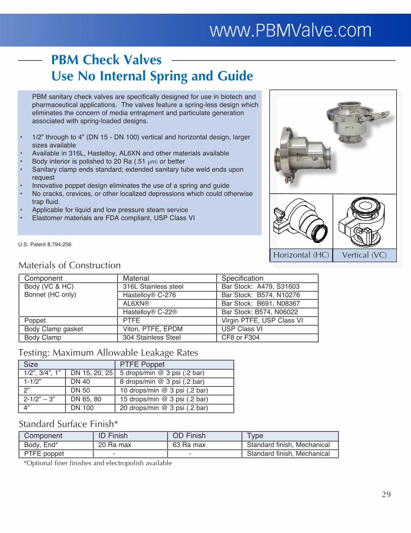
PBM sanitary check valves are specifically designed for use in biotech and pharmaceutical applications. The valves feature a spring-less design which eliminates the concern of media entrapment and particulate generation associated with spring-loaded designs.
• 1/2” through to 4” (DN 15 - DN 100) vertical and horizontal design, larger sizes available
• Available in 316L, Hastelloy, AL6XN and other materials available• Body interior is polished to 20 Ra (.51 µm) or better • Sanitary clamp ends standard; extended sanitary tube weld ends upon
request• Innovative poppet design eliminates the use of a spring and guide• No cracks, crevices, or other localized depressions which could otherwise
trap fluid.• Applicable for liquid and low pressure steam service• Elastomer materials are FDA compliant, USP Class VI
Vertical (VC)Horizontal (HC)Materials of Construction
Testing: Maximum Allowable Leakage Rates
Standard Surface Finish*
Component Material SpecificationBody (VC & HC)Bonnet (HC only)
316L Stainless steel Bar Stock: A479, S31603Hastelloy® C-276 Bar Stock: B574, N10276AL6XN® Bar Stock: B691, N08367Hastelloy® C-22® Bar Stock: B574, N06022
Poppet PTFE Virgin PTFE, USP Class VIBody Clamp gasket Viton, PTFE, EPDM USP Class VIBody Clamp 304 Stainless Steel CF8 or F304
Size PTFE Poppet1/2”, 3/4”, 1” DN 15, 20, 25 5 drops/min @ 3 psi (.2 bar)1-1/2” DN 40 8 drops/min @ 3 psi (.2 bar)2” DN 50 10 drops/min @ 3 psi (.2 bar)2-1/2” – 3” DN 65, 80 15 drops/min @ 3 psi (.2 bar)4” DN 100 20 drops/min @ 3 psi (.2 bar)
Component ID Finish OD Finish TypeBody, End* 20 Ra max 63 Ra max Standard finish, Mechanical PTFE poppet - - Standard finish, Mechanical*Optional finer finishes and electropolish available
PBMCheckValvesUseNoInternalSpringandGuide
U.S. Patent 8,794,256

30
n Cleanable and maintainablen Reliable — Simple design, easy to maintain
n 316L Stainless material
n All materials are FDA compliant
n Swickle outlet
n Autoclavable
n Torchable for sterilization
n Large nylon 6/6 handle knob
n Replaceable O-ring, TFMTM seat
n 3/8” straight thread, 1/4” MNPT, and sanitary clamp inlet connections
RisingStemSamplingValves
The actuator is single acting, pneumatic and is spring return to the closed valve position and operates with 50 to 120 psig air pressure. A 1/4-inch FNPT tap is provided for connecting the air line from the solenoid valve. It features an adjustment to set full open flow to the desired level. This flow can be adjusted from a trickle flow to as much as 5 gpm at 25 psi pressure drop. A knob is provided to operate the valve manuallyin lieu of operating the valve with air.
Option:Position of the valve can be detected with one or two IFM Efector MK 5005 proximity switches that sense the position of a magnet above the piston in the valve. These low current switches operate at voltages of 10 to 30 VDC.
Sample process media quickly and easily with PBM’s Sampling Valve. Special pad design minimizes dead space. Easy CIP with Purge Ports and Milled Ball Flats ensures reliable samples. Valve can be shipped pre-mounted to piping for easy installation. Ideal for heavy duty and sanitary applications. Manual valve standard.
Sizes: • 1/2” - 2”Materials: • 316 & 316L S/S • Hastelloy®
• Titanium • Others
Options: • Actuation • Steam • Polishing
ActuatedSamplingValves
Features:
31
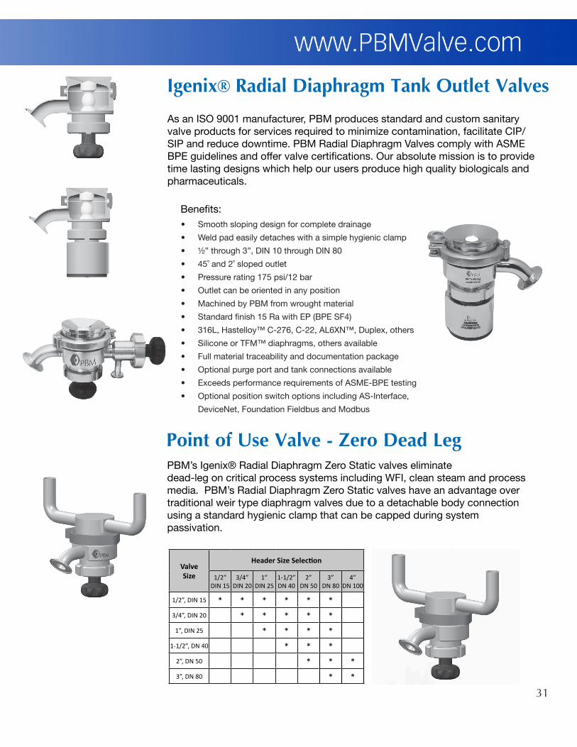
Igenix®RadialDiaphragmTankOutletValves
As an ISO 9001 manufacturer, PBM produces standard and custom sanitary valve products for services required to minimize contamination, facilitate CIP/SIP and reduce downtime. PBM Radial Diaphragm Valves comply with ASME BPE guidelines and offer valve certifications. Our absolute mission is to provide time lasting designs which help our users produce high quality biologicals and pharmaceuticals.
• Smooth sloping design for complete drainage
• Weld pad easily detaches with a simple hygienic clamp
• ½” through 3”, DIN 10 through DIN 80
• 45˚ and 2˚ sloped outlet
• Pressure rating 175 psi/12 bar
• Outlet can be oriented in any position
• Machined by PBM from wrought material
• Standard finish 15 Ra with EP (BPE SF4)
• 316L, Hastelloy™ C-276, C-22, AL6XN™, Duplex, others
• Silicone or TFM™ diaphragms, others available
• Full material traceability and documentation package
• Optional purge port and tank connections available
• Exceeds performance requirements of ASME-BPE testing
• Optional position switch options including AS-Interface,
DeviceNet, Foundation Fieldbus and Modbus
PBM’s Igenix® Radial Diaphragm Zero Static valves eliminate dead-leg on critical process systems including WFI, clean steam and process media. PBM’s Radial Diaphragm Zero Static valves have an advantage over traditional weir type diaphragm valves due to a detachable body connection using a standard hygienic clamp that can be capped during system passivation.
PointofUseValve-ZeroDeadLeg
Benefits:
ValveSize
Header Size Selection
1/2”DIN 15
3/4”DIN 20
1”DIN 25
1-1/2”DN 40
2”DN 50
3”DN 80
4”DN 100
1/2”, DIN 15 * * * * * *
3/4”, DIN 20 * * * * *
1”, DIN 25 * * * *
1-1/2”, DN 40 * * *
2”, DN 50 * * *
3”, DN 80 * *

32
Unliketraditionalballvalves,PBM’sself-cleaningvalvewithAdjust-O-Seal®thoroughlycleansvalveinternalsduringCIPinthefullopenposition.PBM’sself-cleaningballvalvealsoprovidesfull,unobstructedflowandbidirectional,bubble-tightshutoff.Thesearesignificantadvantagesoverfloatingballdesigns,aswellasdiaphragmandbutterflyvalves.
Cleanablewithoutexternalpurgeportsorvalveremoval QuickLineChangeovers Fire-RatedOption–testedtoAPI-607
n USP Class VI elastomers and FDA complaint materials
n Eliminates downtime and maintenance costs associated with removing valves for cleaning.
n Adjustable seats (Adjust O-Seal®) allows valve to retain bidirectional seating.
n Provides full unobstructed flow. Flow of a 1” PBM valve is comparable to a 2” diaphragm valve.
n True-Bore® design ideal for pigging systems
n Certified Material Test Reports (CMTRS) provided for wetted components
n Independent Test Reports available
SelfCleaningBallValves
Problem:Cleaning valves and piping systems is critical in sanitaryapplications.Ifvalvesarenotthoroughlycleaned,productistrappedinthevalvecavitythatcancontaminatethenextbatchofproduct.
Solution:PBM’s self-cleaning ball valve design allows full CIP/SIPaccesstoallvalveinternalsinthefullopenposition.Thisallowsfirsttheprocessandthenthecleaningsolutionandrinse solution to flow freely throughout the body cavitywhenthevalveisintheopenposition.

33
PBMPinchValvesshutoffmediaflowbyexertingaclampingforceonyourexistingbraidedhoseandcleartubing.
Igenix®PinchValves
Features:• PBM’suniquedesignofferstrue“FailClosed”withoutair-assistfor
flexibletubingsizesuptoandincluding1”,25.4mmID.
• Fitsoverexistingtubingwithouttheneedforprocessbreaks.• Hasabsolutelynocontactwithanyprocessmedia,thuswill
neverintroducecontaminants.• Forautomatedversion,designedtofunctionwithactuatorpressure
aslowas60PSIG,4.1bargwithavarietyofoptionallimitswitches. • Canbefittedwithlimitswitchesand/orpositionsensorsforyour
monitoring/flowcontrolneeds.• Modularsafetycovershieldsthepinchareawhenthevalveisinservice.
Itcanbeopenedtoload/unloadthevalvewithouttheneedforprocessbreaksorcompleteremovalfromthevalvebody.
• Testedandproventoprovideabsoluteshutoffontubing.Independenttestreportavailableonflexiblebraidedhoseandcleartubingonrequest.
PBMAutomatedPinchValves• VisualIndicatorstandard• OptionalLimitSwitch• Completeshutoffforallsizes• ModularSafetyCover
PinchValveApplications:
ManualValves• ShutoffvalvesonBagtotes
• ManualflowcontrolonbenchtopUFsystems
AutomatedValves:
• On/OffvalvesonautomatedUFandChromatographyskids
• ValveswithpositionersforflowandpressurecontrolonautomatedUFandChromatographyskids
Refer to PBM Pinch Brochure for dimensions and technical information.

34
Benefits: The spray nozzle is not exposed to the inside of the vessel. This minimizes the potential for clogging or damage caused either by the process or by scraping the inside tank walls during cleaning or processing.n Valve mounts flush with the inside vessel wall, minimizing dead space.n Valve can be located anywhere on the vessel to accommodate specific needs.n Many standard nozzles can be used in the Angle Stem Spray Ball Valve.n Angle Stem Spray Ball Valve allows actuator clearance on jacketed or insulated tanks.n Easily used while still maintaining a vacuum.
For cleaning inside tanks and other vesselsSprayBallValves
FlushTankSamplingValves
Sizes: • 1/2” - 2”Materials: • 316 & 316L S/S • Hastelloy • Titanium • Others
Options: • Actuation • Steam • Polishing • Sample Cup Ball
Sample process media quickly and easily with PBM’s Sampling Valve. Special pad design minimizes dead space. Easy CIP with Purge Ports and Milled Ball Flats ensures reliable samples. Valve can be shipped pre-mounted to piping for easy installation. Ideal for heavy duty and sanitary applications.
Manual valve standard.

35
Features:n Eliminates dead-legs in purified water systems and clean steam systemsn Compact size - short branch geometryn 316L wrought low ferrite stainless steel, other alloys availablen Manual or pneumatic operation with optional device netn Mechanical and electro-polished surfacesn Fully drainablen Adjustable seats (Adjust-O-Seal®) resulting in both upstream and downstream seal.n Optional purge porting available
PBM’s Z-BallTM, zero dead leg ball valve replaces traditional diaphragm valve coupled with a ball valve design used as a sterile barrier for purified water system loops and clean gas utilities. For clean steam header sterilization, the PBM valve is opened to introduce clean steam into the process loop. In a closed position, to prevent condensate from accumulating, the purge port in the valve body removes condensate through trap to drain.
This design offers PBM the ability to provide an ultra-sanitary process isolation valve which seals on both upstream and downstream seats resulting in significant savings compared to traditional methods of using a combination diaphragm valve coupled with a ball valve.
Z-BallTM-ZeroDeadLegBallValveDesign
Holes will allow branch side to flow (clean steam/CIP) into valve body and drain through purge port maintaining isolation from run side
Branch sideflow direction
Run sideRun side (upstream)
Holes upstream will allow run side to drain

36
Fabflex Manifolds are space-saving pipe and valve configurations designed to accommodate special industrial and sanitary applications. Can be shipped in lengths up to 18’, with multiple manual and automated valves pre-installed. 100% testing before shipment ensures proper performance. Minimal dead space reduces areas where media could become trapped. Blank valve pads can be provided to accommodate future process expansion.
Valve Sizes: • 1/4” - 6”Materials: • 316 & 316L S/S • Carbon Steel • Hastelloy®
Options: • Fire-Test • CIP/SIP • Cavity Fillers • Actuation • Steam • Polishing & Electropolishing
PBM’s Adjustable Seat design combined with this material transition could be the answer to failing dielectric unions in your header systems. PBM’s design provides an ideal spec transition and “leak resistant” dielectric union.
Sizes: • 1/2” - 2”Materials: • 316/316L S/S • 922 Bronze • Others
Options: • Interchangeable Seats • Stem Extension • Direct Mount Actuation • Locking Handle • Body Cavity Fillers
ProcessBreakValves
Fabflex®
Manifolds
37
Use PBM’s 2-Way Control Valves in industrial and sanitary throttling or shearing applications to accurately control the flow of liquids or thick media. These valves feature characterized balls with various port shapes, including “V.” Manual valve standard.
Sizes: • 1/2” - 6”Materials: • 316 & 316L S/S • Hastelloy®
• Others
Options: • Actuation • 30°, 45°, 60° V Angles • Slotted • Locking Handle • Polishing & Electropolishing
ControlValves
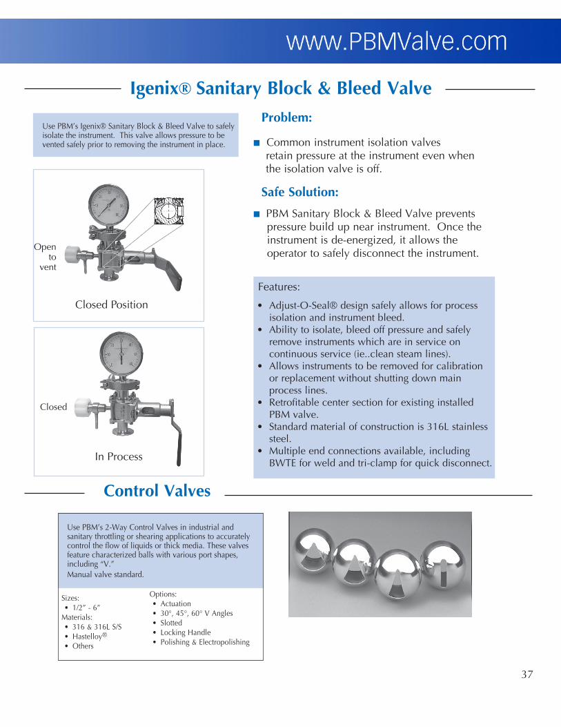
Igenix®SanitaryBlock&BleedValve
Use PBM’s Igenix® Sanitary Block & Bleed Valve to safely isolate the instrument. This valve allows pressure to be vented safely prior to removing the instrument in place.
In Process
Closed Position
Features:
• Adjust-O-Seal® design safely allows for process isolation and instrument bleed.• Ability to isolate, bleed off pressure and safely remove instruments which are in service on continuous service (ie..clean steam lines).• Allows instruments to be removed for calibration or replacement without shutting down main process lines.• Retrofitable center section for existing installed PBM valve.• Standard material of construction is 316L stainless steel.• Multiple end connections available, including BWTE for weld and tri-clamp for quick disconnect.
Problem:
n Common instrument isolation valves retain pressure at the instrument even when the isolation valve is off.
SafeSolution:
n PBM Sanitary Block & Bleed Valve prevents pressure build up near instrument. Once the instrument is de-energized, it allows the operator to safely disconnect the instrument.
Closed
Open to
vent

38
ActuatorFeatures
Nominal Values:Pressure rating of 120 psig (8 barg). Standard temperature range is -4°F to 185°F (-20°C to 85°C). High temperature range is -4°F to 302°F (-20°C; 150°C). Low temperature range is -40°F to 185°F (-40°C to 85°C). Pre-lubricated for life of actuator on assembly. Fully tested on manufacture 100%.
Rotation adjustment 0-90°From MOD. 52 up to 200n standard + or - 5o in both clockwise and counterclockwise direction by means of adjusting screws outside the internal air supply chambersn standard visual position indicators
MOD. 270n standard + or - 5o in counterclockwise direction by means of adjusting screws in the capsn kit for + or - 5o in clockwise direction available on request
External connectionn Namur pinion mountingn Namur solenoid valve mountingn Bottom of pinion according to ISO 5211-DIN 3337n Optional Beacon Indicator
Operating PressureRange - 40 psig to 120 psig (2.8 barg to 8 barg)
Operating MediaClean, dry air or clean, dry, non-corrosive gas
Stroke90 degrees standard
Steel pinionn Nickel-plated for resistance to corrosionn Stainless steel (optional) for corrosive environmentsn Anti-blowout design
Body manufactured from extruded aluminum UNI 6060n Hard-coat anodized as standard finish 45-50 (micron)n Good wear resistancen Bore finished to high standard to ensure low friction and long life
Sealsn NBR standardn Viton high temperature (optional)n HNBR low temperature (optional)
Refer to Series “C” PBM Actuator Brochure for dimensions and technical information.
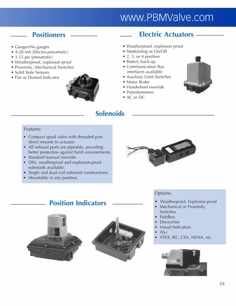
39
Features:
• Compact spool valve with threaded port, direct mounts to actuator• All exhaust ports are pipeable, providing better protection against harsh environments.• Standard manual override.• DIN, weatherproof and explosion-proof solenoids available.• Single and dual-coil solenoid constructions.• Mountable in any position.
Positioners ElectricActuators
PositionIndicators
Solenoids
Options:
• Weatherproof, Explosion proof• Mechanical or Proximity Switches• Fieldbus• DeviceNet• Visual Indication• AS-i• ATEX, IEC, CSA, NEMA, etc.
• Weatherproof, explosion proof• Modulating or On/Off• 2, 3, or 4 position• Battery back-up• Communication Bus interfaces available• Auxiliary Limit Switches• Motor Brake• Handwheel override• Potentiometers• AC or DC
• Gauges/No gauges• 4-20 mA (Electro-pneumatic)• 3-15 psi (pneumatic)• Weatherproof, explosion proof• Proximity, Mechanical Switches• Solid State Sensors• Flat or Domed Indicator

www.PBMValve.comVisit PBM Valve online to find the PBM domestic or
international representative near you. © Copyright 2016 PBM, Inc. LT-34 8/16
PBM, Inc.
United States • Canada • Australia • Mexico • Brazil • Argentina • Chile • UAEUnited Kingdom • Germany • Sweden • Denmark • Spain • Belgium • France • Ireland
Switzerland • Austria • The Netherlands • South Africa • India • South KoreaTaiwan • China • Thailand • Singapore • Saudi Arabia • Malaysia • Vietnam
PBM,Inc.•1070SandyHillRoad,Irwin,PA15642Phone:800.967.4PBM•724.863.0550•Fax:724.864.9255E-mail:[email protected]