adly atv-300su (i)9261-2006 service
TRANSCRIPT

ADLY MOTO
SERVICE MANUAL
ATV-300S/U(
OCTOBER, 2006 High Power Engine HER
CHEE INDUSTRIAL CO., LTD.
ADLY MOTO
Foreword
This service manual contains information on servicing ATV-300
This manual is written for use as a guideline only. It is recommended that any mechanic, with or without sufficient experience, thoroughly read through the manual and only attempt to service those areas that are fully understood in accordance with the guidelines provided by this manual. For fully qualified mechanics, this manual supplies service data necessary for repairs and maintenance. It is highly recommended that a qualified mechanic, regardless of technical level, should study the service manual in full before attempting service on ATV-300
All the data and diagrams provided in this service manual are valid at the time of
publication. Information may be updated without notice due to improvements or
upgrades.
No quotation, reproduction, or reprint of the service manual, as a whole or in part,
will be permitted without the express written consent from ADLY Motor sports.
ADLY MOTO
I N D E X
Assembly Instruction / Pre-Delivery Information --------------------0
Information for Preparation-----------------------------------------------1
Check and Adjust-----------------------------------------------------------2
Cover parts / Muffler-------------------------------------------------------3
Engine-
Lubrication System---------------------------------------------------------4
Fuel System------------------------------------------------------------------5
Engine remove and installation-------------------------------------------6
Cylinder Head / Valve------------------------------------------------------7
Cylinder / Piston------------------------------------------------------------8
Clutch / Starting System---------------------------------------------------9
Crank case / Crank shaft--------------------------------------------------10
Chassis-
Front wheel / Brake / Suspension / Steering----------------------------11
Rear wheel / Brake / Suspension ----------------------------------------12
Electrical devices-----------------------------------------------------------13
Wiring diagram-------------------------------------------------------------14

ADLY MOTO
MAINTENANCE SPECIAL TOOLS
Install crankshaft tool
(TLH3-01)
Bearing puller set
(TLH3-04)
Fly wheel puller
(TLH3-02)
Valve install / remove tool
(TLH3-03)
Valve adjustment tool
(TLH3-05)

ADLY MOTO
ASSEMBLY INSTRUCTION
1. Take out the battery and fill with acid liquid. Pre-charge the battery will extend its life. The preparation and charge procedure is based on the battery’s instruction.
2. Install the front and rear wheels and parts in the following order: A. 18×40×4.5mm washer B. 18mm hex-bolt (torque 14 kg-m, 135 N-m) C. Cotter pin (open up the end after installed) D. Rubber cap.
3. Install the front bumper.
4. Set the handle bar into the lock-pin of the steering base. Tie-up the 4 hex-socket bolts. Install the front cover into the handlebar.
5. Install battery with the red wire to positive (+) first and the black wire to the negative (-).
Use rubber strip to fix the battery onto frame.
6. Check the oil gage to see if the oil quantity is on the upper position. The oil type is 10W/40 for normal condition. It would be better for the engine to choose synthetic type. Fill up unleaded gasoline to operate.
Be sure the arrow mark on the fuel valve arm petcock is set into the correct position.(ON).
7. Turn on the main switch and try to start-up the engine. In order to use the electric starter, you need to check the following:
A. Check the neutral indication light should be on. B Press the electric starter bottom to start.

ADLY MOTO
P.D.I. (Pre-Delivery Inspection)
1. Record the frame and engine number into the owner’s manual.
2. Check that all tires have correct pressure specified on the tire or in the owner’s manual.
3. Engine oil is enough.
4. Battery is installed properly.
5. All cables are adjusted properly. (brake, throttle, choke)
6. Fuel tank has enough gasoline to operate.
7. Check the suspension and drive chain for proper setup.
8. Check all electrical components and lights are working properly.
9. Make sure that the owner’s manual and tool bag are installed on left side of the seat in the tool box.

ADLY MOTO
1-1
INFORMATION FOR PREPARATION Attention on Operation
All washers, oil rings, clamp rings, opening pins shall be duly replaced by a new item when dismounted.
Locking of all screws, nuts, cross screws shall be performed in the order of first the large screws and then the small ones and from inside to outside in opposite angles by tightening the torque locks.
All items must use original parts, pure oil and greases.
All service shall use special tools and general tools to repair.
All dismounted items requiring for checks shall be duly cleaned and for assembly, all items shall be duly lubricated.

ADLY MOTO
1-2
INFORMATION FOR PREPARATION Attention on Operation
Certified lubricants in cans shall be used on all the elements to be lubricated.
After assembly, performance of all elements shall be duly checked and the locking shall be duly verified.
In case of an operation is performed by over 2 people, the assignment shall be conducted in coordination and safety shall be the first priority.
Definition of signs: The sign given in the Service Manual shall refer to the operation methods and observation.
OIL: Lubrication by designated lubricant.
GREASE: Lubrication by grease
Special Tool: Parts on which special tools shall be used
General Tool: General tools shall be used
New: Replace by new items after dismounting
Attention
Dangerous and important operations

ADLY MOTO
1-3
INFORMATION FOR PREPARATION
SPECIFICATION ( UTILITY )
TYPE ATV-300U (92/61)
LENGTH 1800 mm
WIDTH 1030 mm
HEIGHT 930 mm
SEAT HEIGHT 800 mm
WHEEL BASE 1150 mm
NET WEIGHT 200 kg
ENGINE TYPE 4-STROKE, Single Cylinder
COOLING AIR COOLED
DISPLACEMENT 282 c.c.
BORE STROKE Ø 74 × 65.5 mm
TRANSMISSION Manuel , 5 speed First gear 0.095
Second gear 0.139 Third gear 0.190 Forth gear 0.242 Fifth gear 0.299
Reverse gear 0.065 CLUTCH TYPE Wet, Multi-disc
ENGINE OIL (CHANGE) 10W/40 (Standard), 2.0 Lit
ENGINE IDLE SPEED 1400 100 rpm
VALVE CLEARANCE 0.08 0.12 mm
STARTING Electric starter and pull start
SPARK PLUG NGK DR8EA
SPARK PLUS GAP 0.6~0.7 mm
IGNITION C.D.I
SUSPENSION Front Double A-Arm with preload adjustable shock Rear Swing arm with preload adjustable shock
BRAKE Front : Double Disc , Rear: Disc
BATTERY 8 Amps/h, Maintenances Free
FINAL DRIVE Chain
FRONT TIRE 21×7-10 (Optional 22 8-10)
REAR TIRE 21×10-8 (Optional 22 11-10)
FRONT BUMPER (LOAD)) 30kg
REAR BUMPER (LOAD)) 45kg

ADLY MOTO
1-4
INFORMATION FOR PREPARATION
SPECIFICATION ( SPORTY )
TYPE ATV-300S (92/61)
LENGTH 1740 mm
WIDTH 1050 mm
HEIGHT 1080 mm
SEAT HEIGHT 820 mm
WHEEL BASE 1150 mm
NET WEIGHT 190 kg
ENGINE TYPE 4-STROKE, Single Cylinder
COOLING AIR COOLED
DISPLACEMENT 282 c.c.
BORE STROKE Ø 74 × 65.5 mm
TRANSMISSION Manuel , 5 speed First gear 0.095
Second gear 0.139 Third gear 0.190 Forth gear 0.242 Fifth gear 0.299
Reverse gear 0.065 CLUTCH TYPE Wet, Multi-disc
ENGINE OIL (CHANGE) 10W/40 (Standard), 1.6 Lit
ENGINE IDLE SPEED 1400 100 rpm
VALVE CLEARANCE 0.08 0.12 mm
STARTING Electric starter and pull start
SPARK PLUG NGK DR8EA
SPARK PLUS GAP 0.6~0.7 mm
IGNITION C.D.I
SUSPENSION Front Double A-Arm with preload adjustable shock Rear Swing arm with preload adjustable shock
BRAKE Front : Double Disc , Rear: Disc
BATTERY 8 Amps/h,, Maintenances Free
FINAL DRIVE Chain
FRONT TIRE 21×7-10 (Optional 22 8-10)
REAR TIRE 21×10-8 (Optional 22 11-10)

ADLY MOTO
1-5
INFORMATION FOR PREPARATION
LOCKING TORQUE
The standard locking torque shall apply in case of no specification.
STANDARD TORQUEType Locking Torque (kg-m) Type Locking Torque (kg-m)
5mm Bolt, Nut 0.5 5 mm Screw 0.4 6mm Bolt, Nut 1.0 6 mm Screw 0.9 8mm Bolt, Nut 2.2 6 mm Flange Bolt, Nut 1.2 10mm Bolt, Nut 3.5 7 mm Flange Bolt, Nut 2.1 12mm Bolt, Nut 5.5 8 mm Flange Bolt, Nut 2.7 18mm Bolt, Nut 15.0 10 mm Flange Bolt, Nut 4.0 18mm Lock nut 11.0
CHASSISLocking Place Quantity Dia. (mm) Torque (kg-m) Remark
Handle bar bottom flange nut 2 10 4.0 Nylon insert type Ball joint fixed nut 4 10 4.0 Nylon insert type Engine mounting flange nut 4 8 3.5 Engine mounting bracket bolt 2 10 4.0 Foot rest flange bolt 6 8 4.0 Rear swing arm fixed nut 1 14 9 Nylon insert type Rear brake panel flange bolt 4 12 7 Front suspension fixed nut 4 10 4.0 Nylon insert type Rear suspension flange bolt 2 10 4.0 Front rim nut 2 18 15 Rear rim nut 2 18 15
ENGINELocking Place Quantity Dia. (mm) Torque (kg-m) Remark
Breather separator Allen bolt 1 6 1.2 Hex socket flange boltCam chain tensioner mounting bolt 2 6 1.2 Hex flange boltCam sprocket bolts 2 7 2.1 Hex flange bolt Clutch center locknut 1 18 11.0 Locknut Clutch lifter plate bolts 4 6 1.2 Hex bolt Crankcase cover bolts (L/R) 24 6 1.0 Crankcase bolts 14 6 1.2 Hex flange Bolt Cylinder base bolts 2 6 1.0 Cylinder head cover flange bolts 13 6 1.2 Hex flange Bolt Cylinder head cap nuts 4 10 4.0 Hex acorn washer face nut
1 6 1.0 Oil pipe bolts 1 7 1.2
Gearshift return spring pin 1 8 2.2 Gearshift drum shifter pin 2 8 2.2

ADLY MOTO
1-6
INFORMATION FOR PREPARATION The following drawing that shows the disassembling situation of the cover parts for ATV-300U.
ADLY MOTO
1-7
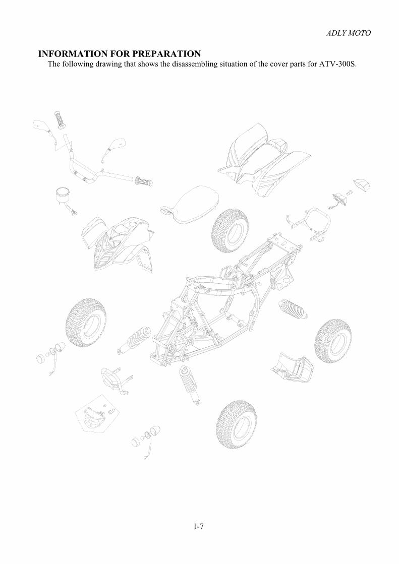
INFORMATION FOR PREPARATION The following drawing that shows the disassembling situation of the cover parts for ATV-300S.
ADLY MOTO
1-8
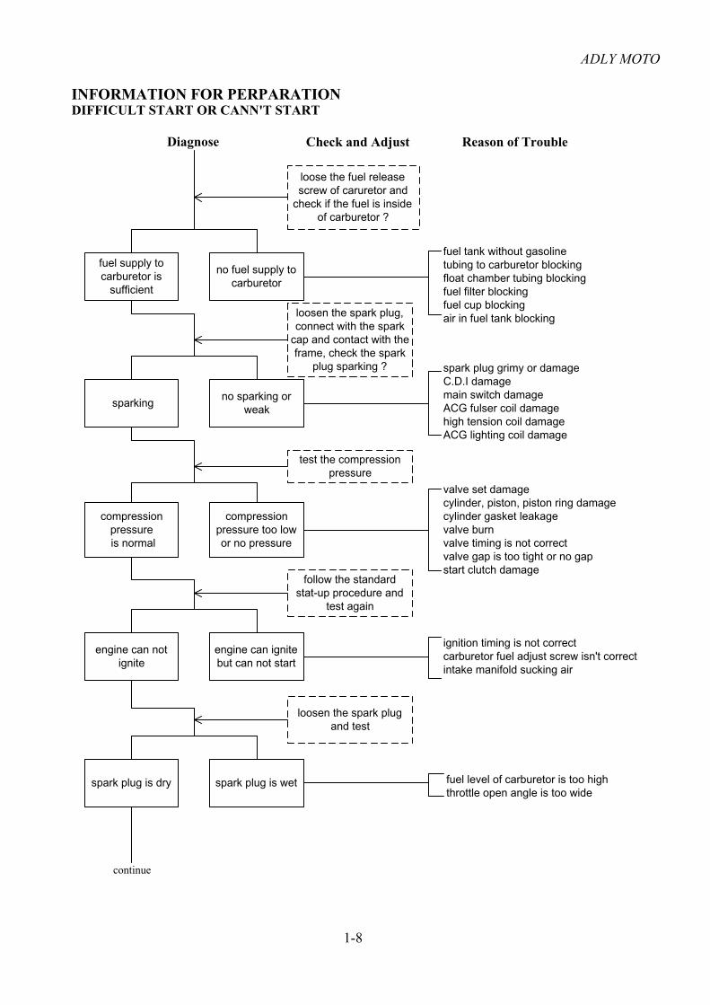
fuel supply tocarburetor is
sufficient
no fuel supply tocarburetor
loose the fuel releasescrew of caruretor and
check if the fuel is insideof carburetor ?
sparkingno sparking or
weak
compressionpressure is normal
compressionpressure too lowor no pressure
engine can notignite
engine can ignitebut can not start
spark plug is dry spark plug is wet
loosen the spark plug,connect with the spark
cap and contact with theframe, check the spark
plug sparking ?
test the compressionpressure
follow the standardstat-up procedure and
test again
loosen the spark plugand test
Diagnose Check and Adjust Reason of Trouble
fuel tank without gasolinetubing to carburetor blockingfloat chamber tubing blockingfuel filter blockingfuel cup blockingair in fuel tank blocking
spark plug grimy or damageC.D.I damagemain switch damageACG fulser coil damagehigh tension coil damageACG lighting coil damage
valve set damagecylinder, piston, piston ring damagecylinder gasket leakagevalve burnvalve timing is not correctvalve gap is too tight or no gapstart clutch damage
ignition timing is not correctcarburetor fuel adjust screw isn't correctintake manifold sucking air
fuel level of carburetor is too highthrottle open angle is too wide
DIFFICULT START OR CANN'T START
continue
INFORMATION FOR PERPARATION

ADLY MOTO
1-9
engine speedgoes up
engine speed can'tgoes up fully
ignite timing iscorrect
ignite timing isn'tcorrect
valve gap is correctvalve gap
isn't correct
compression pressureis normal
compressionpressure
is too low
no blocking blocking
spark plug normal spark plug stain
oil quantity is normal
oil quantity is too rich
normal abnormal
normal over heat
no knocking knocking
INFORMATION FOR PREPARATIONREVOLUTION NOT SMOOTH , LOST POWER
Diagnose
start engine andgo up speed slight
adjusting ignitetiming
adjusting valve gap
test compressionpressure
check carburetorblocking ?
loosen spark plugand check
check the oilquantiity in
crankcase is toorich or dirty?
check cylinder headlubricating ?
engine over heat
increase enginespeed or continue
turning at highspeed
Check and Adjust
air cleaner blockingfuel supply isn't smoothair hole of air tank blockingexhaust pipe blockingmanual choke stay onfuel cup damage
C.D.I damagepulser coil damage
valve gap adjusting isn't correctvalve seat over abrade
valve seat damagecylinder, piston abradecylinder gasket leakagevalve timing isn't correct
cleaning carburetor
cleaning the stainspark plug type isn't correct
oil flowing is too richoil flowing is too leanoil doesn't circulate
oil tubing blockingoil supply is too lean
cylinder, piston abrademixutre gases is too leancarbon residue in combustion chamberis too muchignition timing is too earilyfuel isn't good
clutch plate slidingmixutre gases is too leancarbon residue in combustion chamberis too muchignition timing is too earilyfuel isn't good
Reason of Trouble
continue
ADLY MOTO
1-10
normal abnormal
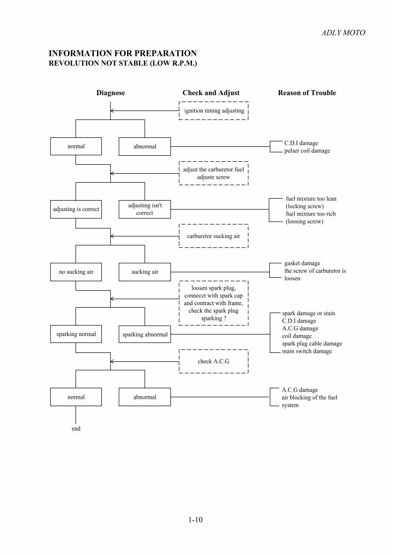
INFORMATION FOR PREPARATIONREVOLUTION NOT STABLE (LOW R.P.M.)
Diagnose Check and Adjust
adjusting is correctadjusting isn't
correct
no sucking air sucking air
sparking normal sparking abnormal
normal abnormal
ignition timing adjusting
adjust the carburetor fueladjuste screw
carburetor sucking air
loosen spark plug,connecct with spark capand contract with frame,
check the spark plugsparking ?
check A.C.G
end
Reason of Trouble
C.D.I damagepulser coil damage
fuel mixture too lean(locking screw)fuel mixture too rich(loosing screw)
spark damage or stainC.D.I damageA.C.G damagecoil damagespark plug cable damagemain switch damage
A.C.G damageair blocking of the fuelsystem
gasket damagethe screw of carburetor isloosen

ADLY MOTO
1-11
normal abnormal
INFORMATION FOR PREPARATIONREVOLUTION NOT SMOOTH(HIGH SPEED)
Diagnose Check and Adjust
normal abnormal
normal abnormal
no blocking blocking
valve timing iscorrect
valve timing isn'tcorrect
adjusting ignition timing
adjusting valve gap
check fuel cup supplynormal ?
carburetor blocking
check and adjust valvetiming
Reason of Trouble
C.D.I damage ACG pulse coil damage
fule filter blockingair hole of fuel tank blockingfuel cup damagefuel in tank is not sufficient
camshaft gear mark position isnot correct
normalspring broken or
elastic deformation
end
check the spring of valve
adjusting isn't correctvalve seat damage
cleaning
spring damage

ADLY MOTO
1-12
voltage of batterycan't go up
voltage of batteryis normal
INFORMATION FOR PREPARATIONCHARGE ABNORMAL
Diagnose Check and Adjust
normalmeasure value
too high
battery have voltagebattery have not
voltage
normal abnormal
start engine and measurevoltage of both terminal on
battery
measure the resistance ofACG coil
check the regulator
check socket of regulatorloosen ?
Reason of Trouble
battery damage
coil damageterminal damageYL wire damage
Red wire damage
regulator damagesocket damage
ACG damage(over charge)
main switch at ONthe battery have
voltage
main switch at ONthe battery have no
voltage
normal socket loosen
GR wire broken
regulator damage
socket damage
check the socket ofregulator
check the voltage betweenregulator (+) and frame

ADLY MOTO
1-13
no sparking orweak sparking strong
INFORMATION FOR PREPARATIONSPARK PLUG NO SPARKING
Diagnose Check and Adjust
loosen no loosen
normal abnormal
normal abnormal
normal abnormal
change spark plug andcheck again
check spark plug, cap,ignition coil loosen?
check C.D.I unit socketloosen ?
check the terminal ofC.D.I unit unimpeded?
measure resistance
check relate spare parts
Reason of Trouble
the previous spark plug damage
spark plug cap loosen
main switch damagepulser coil damagecoil damagelighten coil damage
the previous C.D.I unit damage
socket damage
normal abnormal
main switch damagesocket, joint connect abnormal
change CDI unit
abnormal
change ignition coil
the previous coil damage

ADLY MOTO
2-1
CHECK AND ADJUST
INFORMATION
WARNNING Do not start the engine at a close zone, because the exhaust gases from the engine including
some noxious emission such as CO, HC, NOx... etc. that can result serious damage for health. Strictly prohibit using any flammable thing in the working zone, because that can rise fire
easily.
ENGINEITEM SPECIFICATION REMARK
Spark Plug Gap 0.6~0.7 mm
Spark Plug Type DR8EA without resistance
0.08mm intake valve Valve Gap 0.12mm exhaust valve
Idle Speed 1400 100 rpm Engine oil type SAE 10W/40 Synthetic
1.6 L At oil change Engine Oil Capability 2.0 L After engine overhaul
Compression Pressure 13 kg/cm2 1400 rpm Ignite Timing 17 BTDC 1400 100 rpm
CHASSISITEM SPECIFICATION REMARK
Parking brake lever free play 10~20 mm Left lever free play 5~10 mm Throttle free play 2~6 mm Front Tire Pressure 10 psi Check the mark on tire Rear Tire Pressure 10 psi Check the mark on tire Torque of Front Rim Nut 14 kg-m Torque of Rear Rim Nut 14 kg-m
Detailed tire pressure specification please check the marking on tires.
ADLY MOTO
2-2
CHECK AND ADJUST
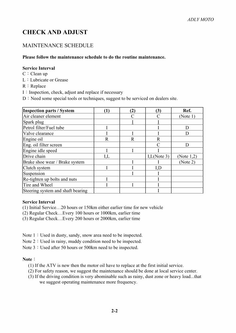
MAINTENANCE SCHEDULE
Please follow the maintenance schedule to do the routine maintenance.
Service Interval C Clean up L Lubricate or Grease R ReplaceI Inspection, check, adjust and replace if necessary D Need some special tools or techniques, suggest to be serviced on dealers site.
Inspection parts / System (1) (2) (3) Ref. Air cleaner element C C (Note 1) Spark plug I IPetrol filter/Fuel tube I I D Valve clearance I I I D Engine oil R R R Eng. oil filter screen C D Engine idle speed I I I Drive chain I,L I,L(Note 3) (Note 1,2) Brake shoe wear / Brake system I I (Note 2) Clutch system I I I,D Suspension I I Re-tighten up bolts and nuts I I Tire and Wheel I I I Steering system and shaft bearing I
Service Interval (1) Initial Service…20 hours or 150km either earlier time for new vehicle (2) Regular Check…Every 100 hours or 1000km, earlier time (3) Regular Check…Every 200 hours or 2000km, earlier time
Note 1 Used in dusty, sandy, snow area need to be inspected. Note 2 Used in rainy, muddy condition need to be inspected. Note 3 Used after 50 hours or 500km need to be inspected.
Note (1) If the ATV is new then the motor oil have to replace at the first initial service. (2) For safety reason, we suggest the maintenance should be done at local service center. (3) If the driving condition is very abominable such as rainy, dust zone or heavy load...that we suggest operating maintenance more frequency.
ADLY MOTO
2-3
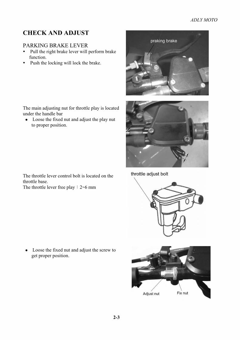
CHECK AND ADJUST
PARKING BRAKE LEVER Pull the right brake lever will perform brake function.Push the locking will lock the brake.
The main adjusting nut for throttle play is located under the handle bar
Loose the fixed nut and adjust the play nut to proper position.
The throttle lever control bolt is located on the throttle base. The throttle lever free play 2~6 mm
Loose the fixed nut and adjust the screw to get proper position.

ADLY MOTO
2-4
CHECK AND ADJUST
SPARK PLUG Pull to remove the spark plug cap. Use tools come with the vehicle to remove the spark plug. If the spark plug grimy or with carbon residue then using the copper brush to clean it.
Spark plug specification DR8EA Resistance
Check the gap of spark plug Gap 0.6~0.7 mm
AIR CLEANER Remove the seat. Pull to open 4 clips on air cleaner cover and remove the cover. Take-out the air filter. Check the filter whether is dirty or damaged. If it‘s dirty or damaged then clean it or change a new one.
AttentionClean the element and frame in a high flash
point solvent squeeze the solvent out of the foam and let the guide and element dry completely.
Check periodIf the ATV often driving at the rainy or
abominable surroundings, please check the filter more frequently.

ADLY MOTO
2-5
CHECK AND ADJUST
VALVE ADJUSTING
AttentionWhen you check or adjust the valve, do it
when the engine temperature is low ( below 35 C)
Remove the timing hole plug and the crankshaft hole plug with screwdriver.
Rotate the flywheel and keep the “T” line aim at the centerline of the inspection hole.
Measure valve clearance with a feeler gauge of the specified thickness.
To adjust the valve clearance, loosen the locknut and turn the adjuster.
AttentionWhen you adjusting the valve, don’t
invert the crankshaft, otherwise cannot adjust the exhaust valve.
Valve gap check and adjust Valve gap IN. 0.08 mm EX. 0.12 mm
Loose the fixed nut and rotating the adjusting nut reach to the proper gap. Tie up the fixing nut and check the gap again.Using the valve gap tool to adjust the valve gap.

ADLY MOTO
2-6
CHECK AND ADJUST
ADJUSTING IDLE SPEED
Engine idle speed adjustment has to do it when the engine is warm.
Connect with the rpm meter then starting the engine.
Before adjusting the idle speed, make sure the spark plug gap is correct. Also, turn the handlebars from left to right and note whether the idle speed changes. If it does, the throttle cable may be incorrectly routed. Be sure to correct this problem before proceeding.
Adjust the idle speed adjust screw reach to the normal idle speed.
The idle speed is about 1400 100 rpm.
IGNITION TIMING
The ignition system of this ATV is controlled by C.D.I unit, thus don‘t need to adjust anything. If the ignition timing isn’t correct then checking the ignition system whether normally.
Remove the 14 mm A.C.G. cap. Using the timing light to check the ignition timing. When the engine speed running at idle, the “F” mark of flywheel should aim at the inspection hole.
Warning Use screw driver to adjust the idle speed to avoid injury.
ADLY MOTO
2-7
CHECK AND ADJUST
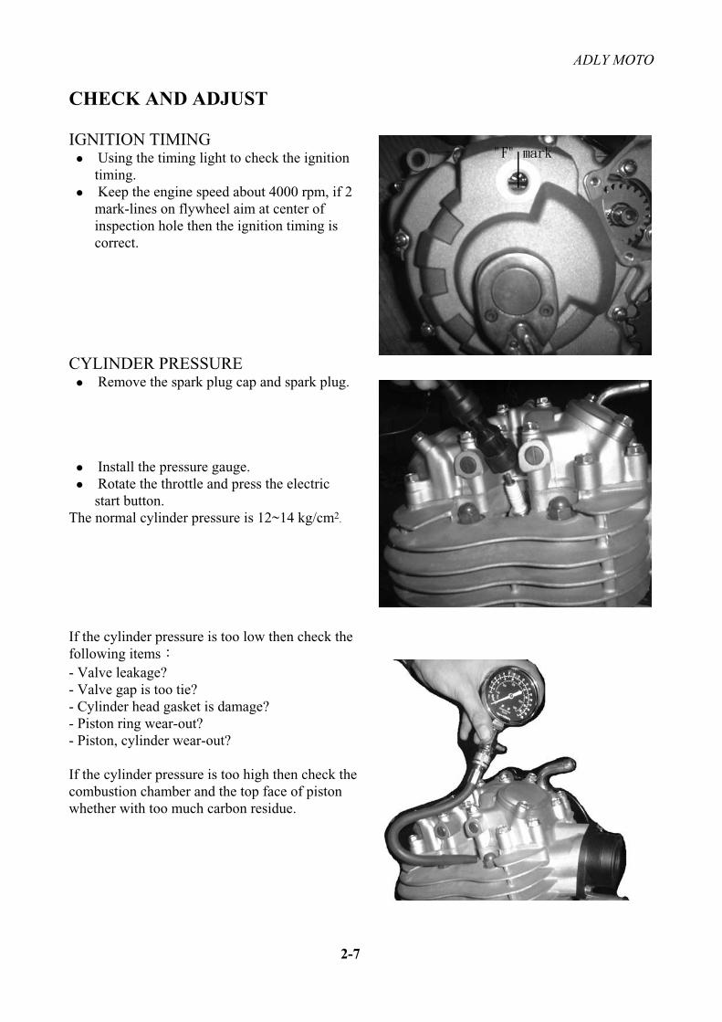
IGNITION TIMING Using the timing light to check the ignition timing. Keep the engine speed about 4000 rpm, if 2 mark-lines on flywheel aim at center of inspection hole then the ignition timing is correct.
CYLINDER PRESSURE Remove the spark plug cap and spark plug.
Install the pressure gauge. Rotate the throttle and press the electric start button.
The normal cylinder pressure is 12~14 kg/cm2.
If the cylinder pressure is too low then check the following items- Valve leakage? - Valve gap is too tie? - Cylinder head gasket is damage? - Piston ring wear-out? - Piston, cylinder wear-out?
If the cylinder pressure is too high then check the combustion chamber and the top face of piston whether with too much carbon residue.

ADLY MOTO
2-8
CHECK AND ADJUST
ENGINE OIL
When you check the quantity of oil, the vehicle has to stay at the ground (flat) level.
Stop the engine and remove the oil level gauge.Unscrew the engine oil filler cap from the right front corner of the engine and pull out the dipstick.
If the oil level is stay within bottom mark of the gauge, then the oil quantity is enough.
Refill the engine oil if it’s too less.
The standard oil type is SAE 10W/40 Re-install the oil level gauge.
Change the engine oilTake-out the oil level gauge. Remove the oil-release bolt underneath the engine and release the oil. Install the oil-release bolt. Fill the engine oil.
Confirm the washer of the bolt whether damaged.
Engine oil quantitydisassemble 2.0 Lit change 1.6 Lit
Check all parts whether leaking, after assembly.
DRIVE CHAIN Check the drive chain condition.
The drive chain should be check, adjust, and lubricate regularly. Inspect the drive chain at a point on the lower run about halfway between the sprockets.
The free play of the drive chain should be between 20~30mm up and down.
20~30mm

ADLY MOTO
2-9
CHECK AND ADJUST
Inspect the front sprocket teeth for excessive wear; mark sure there’s no play in the sprocket.
When install the chain clip, beware the clip direction.
BRAKE SYSTEM Parking brake and rear brake
Check all the brake shoes. If the brake shoes have any dint or wearing very serious then change it.
Check the play of brake lever normal play 10~20 mm
If the brake lever play is too much, adjust the fix bolts on right brake lever. If the play of the rear brake over the normal value then adjust the adjusting nut of rear brake caliper on swing arm.
Adjusting nut must be aligned with pin, any slight deviation may result in braking play change cause danger as brake applied.
STEERINGTurning the steering from right side to left side, check the steering operation.
Be sure the wiring and cable does not affect the steering handle.

ADLY MOTO
2-10
CHECK AND ADJUST
FIXING OF NUTS AND BOLTS Check the fixing nuts, bolts on all parts.
If the nuts, bolts loosen then tie-up with certain locking torque.
SUSPENSIONFront
Holding the brake lever and push the handle bar. Check the fork movement and other parts if is loose or oil leaking.
RearCheck the damping of rear suspension Check the suspension bush function normally.
Inspect all suspension fasteners before riding.
TIRE, RIM Check the tires whether have any nail, broken…etc.Check tire pressure with a gauge that will read accurately at the low pressure used in ATV tires.
The tire pressure can be very depends on different operation condition. Please check the mark on tire for operation pressure tolerance.
ADLY MOTO
2-11
CHECK AND ADJUST
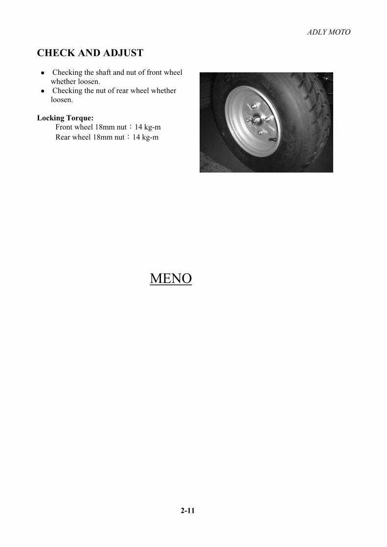
Checking the shaft and nut of front wheel whether loosen. Checking the nut of rear wheel whether loosen.
Locking Torque: Front wheel 18mm nut 14 kg-m Rear wheel 18mm nut 14 kg-m
MENO
ADLY MOTO
COVER PARTS, MUFFLER
Information for preparation Don‘t enforce to remove the cover parts of the ATV, otherwise will cause the connecting nail of cover parts broken. Please according to the operating instruction when assembling the cables and wires
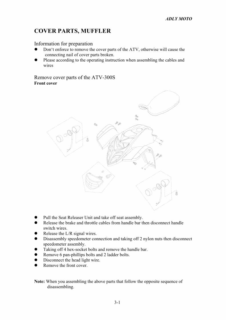
Remove cover parts of the ATV-300S Front cover
Pull the Seat Releaser Unit and take off seat assembly. Release the brake and throttle cables from handle bar then disconnect handle switch wires. Release the L/R signal wires. Disassembly speedometer connection and taking off 2 nylon nuts then disconnect speedometer assembly. Taking off 4 hex-socket bolts and remove the handle bar. Remove 6 pan-phillips bolts and 2 ladder bolts. Disconnect the head light wire. Remove the front cover.
Note: When you assembling the above parts that follow the opposite sequence of disassembling.
3-1
ADLY MOTO
COVER PARTS, MUFFLER
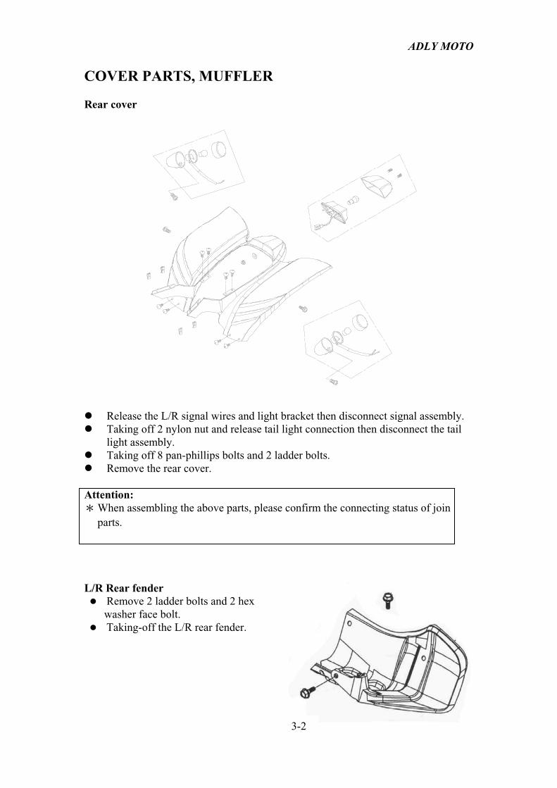
Rear cover
Release the L/R signal wires and light bracket then disconnect signal assembly. Taking off 2 nylon nut and release tail light connection then disconnect the tail light assembly. Taking off 8 pan-phillips bolts and 2 ladder bolts. Remove the rear cover.
Attention: When assembling the above parts, please confirm the connecting status of join
parts.
L/R Rear fender Remove 2 ladder bolts and 2 hex washer face bolt. Taking-off the L/R rear fender.
3-2

ADLY MOTO
COVER PARTS, MUFFLER
Muffler
Locking Torque: Muffler fixed bolt 3.5 kg-m Muffler connect nut 1.2 kg-m
Trouble Diagnose: Exhaust sound level is too high Muffler broken Muffler leakage
Power isn‘t enough Muffler leakage Muffler blocking Muffler with dent
Remove the muffler: Taking-off the 2 nuts that connect to the cylinder. Taking-off the 1 hex flange bolts and 2 hex washer face bolts that fix to the frame. Pull to open 1 exhaust clip and to loose the reed valve comp EX. Pipe. Remove the muffler and gasket.
Note:When you assembling the muffler, don't forget to put gasket on muffler first. Replace a new gasket after dismounting the muffler.
MEMO
3-3

ADLY MOTO
COVER PARTS, MUFFLER
Information for preparation Don‘t enforce to remove the cover parts of the ATV, otherwise will cause the connecting nail of cover parts broken. Please according to the operating instruction when assembling the cables and wires
Remove cover parts of the ATV-300U
Front cover
Pull the Seat Releaser Unit and take off Seat assembly. Taking off 8 hex flange bolts then remove front bumper and luggage rack. Release the brake and throttle cables then disconnect handle switch wires. Release the L/R signal wires and light bracket then disconnect signal assembly. Disassembly speedometer connection and taking off 2 nylon nuts then disconnect speedometer assembly. Taking off 4 hex-socket bolts and remove the handle bar. Remove 6 pan-phillips bolts and 2 ladder bolts. Disconnect the head light wire. Remove the front cover.
Note: When you assembling the above parts that follow the opposite sequence of disassembling.
3-1

ADLY MOTO
COVER PARTS, MUFFLER
Rear cover
Taking off 4 hex flange bolts then disconnect rear bumpers. Release the L/R signal wires and light bracket then disconnect signal assembly. Taking off 2 nylon nut and release tail light connection then disconnect the tail
light assembly. Taking off 8 pan-phillips bolts and 2 ladder bolts. Remove the rear cover.
Attention: When assembling the above parts, please confirm the connecting status of
join parts.
3-2

ADLY MOTO
COVER PARTS, MUFFLER
Muffler
Locking Torque: Muffler fixed bolt 3.5 kg-m Muffler connect nut 1.2 kg-m
Trouble Diagnose: Exhaust sound level is too high Muffler broken Muffler leakage
Power isn‘t enough Muffler leakage Muffler blocking Muffler with dent
Remove the muffler: Taking-off the 2 nuts that connect to the cylinder. Taking-off the 1 hex flange bolts and 2 hex washer face bolts that fix to the frame. Pull to open 1 exhaust clip and to loose the reed valve comp EX. Pipe. Remove the muffler and gasket.
Note:When you assembling the muffler, don't forget to put gasket on muffler first. Replace a new gasket after dismounting the muffler.
MEMO
3-3
ADLY MOTO
LUBRICATION SYSTEM
TROUBLE DIAGNOSE Oil quantity reduced Normal consumption Oil leaking Piston ring wear-out or installed wrong Valve seal wear-out
Engine burn No oil pressure or pressure too low Oil thoroughfare blocking Oil type incorrect
ENGINE OIL & FILTER
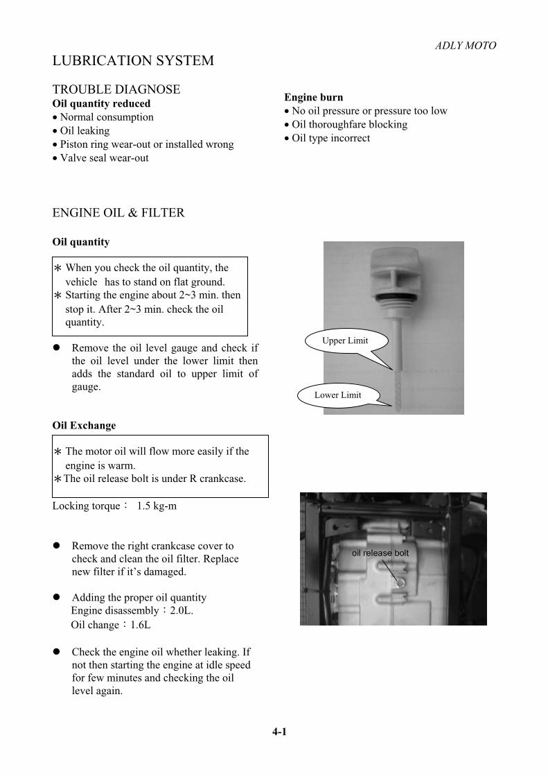
Oil quantity
When you check the oil quantity, the vehicle has to stand on flat ground.
Starting the engine about 2~3 min. then stop it. After 2~3 min. check the oil quantity.
Remove the oil level gauge and check if the oil level under the lower limit then adds the standard oil to upper limit of gauge.
Oil Exchange
The motor oil will flow more easily if the engine is warm.
The oil release bolt is under R crankcase.
Locking torque 1.5 kg-m
Remove the right crankcase cover to check and clean the oil filter. Replace new filter if it’s damaged.
Adding the proper oil quantity Engine disassembly 2.0L.Oil change 1.6L
Check the engine oil whether leaking. If not then starting the engine at idle speed for few minutes and checking the oil level again.
Upper Limit
Lower Limit
4-1

ADLY MOTO
LUBRICATION SYSTEM
CLUTCHRemove
Remove the seat and body cover. ( see 3-1, 3-2 )
Remove 2 10mm Hex-flange bolts on left step bar (foot peg) and 2 Pan-Philips bolts on the rear foot fender. Remove foot peg and fender together.
Take-off 12 bolts on R. crankcase cover and remove the cover. Remove the gasket and 2 dowel pins.
Release the clutch cable fix nut from the left side of the engine. Pull out the cable from the clutch lever on top of right crankcase cover.
R. crankcase
Gasket
dowel pin
4-2

ADLY MOTO
LUBRICATION SYSTEM
Remove 2 M8-25mm hex-flange bolts on master cylinder assembly. This is to lower down the brake pedal for easier.
disassembly.
Release brake pedal reset spring.
Lift the vehicle from right side and flip over to left side. Then remove the oil tube fix bolt on top of right crankcase cover.
Beware not to lost the copper washers.
Remove the nylon insert bolt on reverse stopper lever.
4-3
ADLY MOTO
LUBRICATION SYSTEM
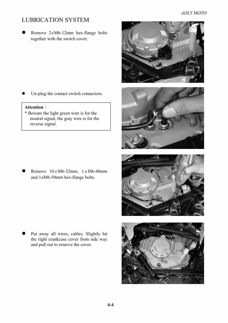
Remove 2 M6-12mm hex-flange bolts together with the switch cover.
Un-plug the contact switch connectors.
Remove 10 M6-32mm, 1 M6-40mm and 1 M6-50mm hex-flange bolts.
Put away all wires, cables. Slightly hit the right crankcase cover from side way and pull out to remove the cover.
4-4
Attention* Beware the light green wire is for the neutral signal, the gray wire is for the reverse signal.

ADLY MOTO
LUBRICATION SYSTEM
Remove the right crankcase cover gasket and beware not to lost the dowel pins.
Remove 4 M6-28mm hex bolts and 4 springs under the clutch lifter plate. Hold the lifter plate together with the needle roller bearing.
Before remove the locknut, punch out the lock section on the nut.
Remove the locknut and clutch center.
4-5

ADLY MOTO
LUBRICATION SYSTEM
Take off the clutch center.
Use reversed procedure to setup the parts that has been removed.
OIL PUMP Remove
Remove the O-ring from the oil pipe. To detach the oil pipe from the crankcase, remove these 2 bolts.Carefully pull the oil pipe off the crankcase.Remove this dowel pin and O-ring from the oil pipe.
Remove the oil pump mounting bolts.
Use reversed procedure to setup the parts that has been removed.
Oil pipe
Attention* Beware all dowel pins are located into
the crankcase. * Replace new gasket of the right
crankcase cover after dis-assembly.
4-6
ADLY MOTO
LUBRICATION SYSTEM
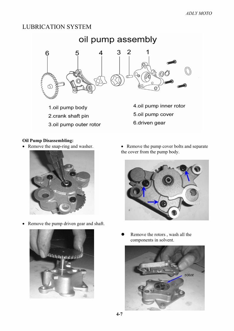
Oil Pump Disassembling: Remove the snap-ring and washer.
Remove the pump driven gear and shaft.
Remove the pump cover bolts and separate the cover from the pump body.
Remove the rotors , wash all the components in solvent.
4-7
rotor

ADLY MOTO
LUBRICATION SYSTEM
Check: Check the gap between the pump body and
outer rotor. The gap limit is 0.25 mm.
Check the gap between inner and outer rotor. The gap limit is 0.2 mm.
Check the gap between the rotors and a straightedge laid across the pump body.
The gap limit is 0.1 mm.
4-8

ADLY MOTO
LUBRICATION SYSTEM
Assembling: Mounting the inner and outer rotor, then install the pump shaft.
When install the pump shaft, beware the dot mark on inner rotor point to the outer rotor dot mark.
Locking the screw. After installed, turning the pump slightly and confirm the function is normal. Add the standard oil in pump then install it.
Installation: Install the pump back to crankcase based on reversed sequence. Install the dowel pin. Discard the old gasket and replace with new R. case cover gasket.
MENO
4-9

ADLY MOTO
5-1
FUEL SYSTEM
TROUBLE DIAGNOSE Start-up function abnormal No spark of spark plug Compression pressure too low No fuel in carburetor Air stock inside air cleaner Stock of fuel pipe Defect of rubber film in carburetor Bad adjustment of fuel level
Too much fuel inside combustion chamber Air stock inside air cleaner Too much fuel cause over flow By passed air sock into fuel system Degeneration of gasoline Starter plunger defect Stock of idle system or chock system
Too thick of Fuel/Air mixture Starter plunger defect Choke cable clagged Float needle valve abnormal Too much fuel cause over flow Stock of airflow inside carburetor Stock of air cleaner Fuel level too high
Muffler make explore noise when deceleration Too much air, too lean fuel Air stop valve abnormal Too thin of F/A mixture at idle speed.
Ignition not continuously when accelerate Ignition system abnormal Too thin of F/A mixture
Difficult to start, Engine stops after start-up, Idle speed not stable Stock of fuel system Ignition system abnormal Fuel/Air mixture too rich or lean Degeneration of gasoline Bad adjustment of idle speed Bad adjustment of fuel quantity Fuel or airflow stock of idle speed Too much fuel cause over flow Stock of starter plunger system Bad adjustment of fuel level
Too thin of Fuel/Air mixture Stock of nozzles inside carburetor Stock of float valve Fuel level too low Stock of fuel system Throttle valve abnormal
ADLY MOTO
5-2
FUEL SYSTEM
CARBURETOR SET UP
Before remove the A/F adjusting screw, remember turns of setup into the end position. The normal setup is 1 to 1 1/4 turns out
After engine warm up, adjust the throttle valve adjusting screw to setup the standard idle speed. Idle engine rev. 1400 100 rpm
Slightly increase the engine speed for few times and release the throttle at idle engine speed. If the engine rev. is not stable, repeat above adjust procedure on fuel adjusting screw and throttle
adjusting screw until the engine speed is normal.
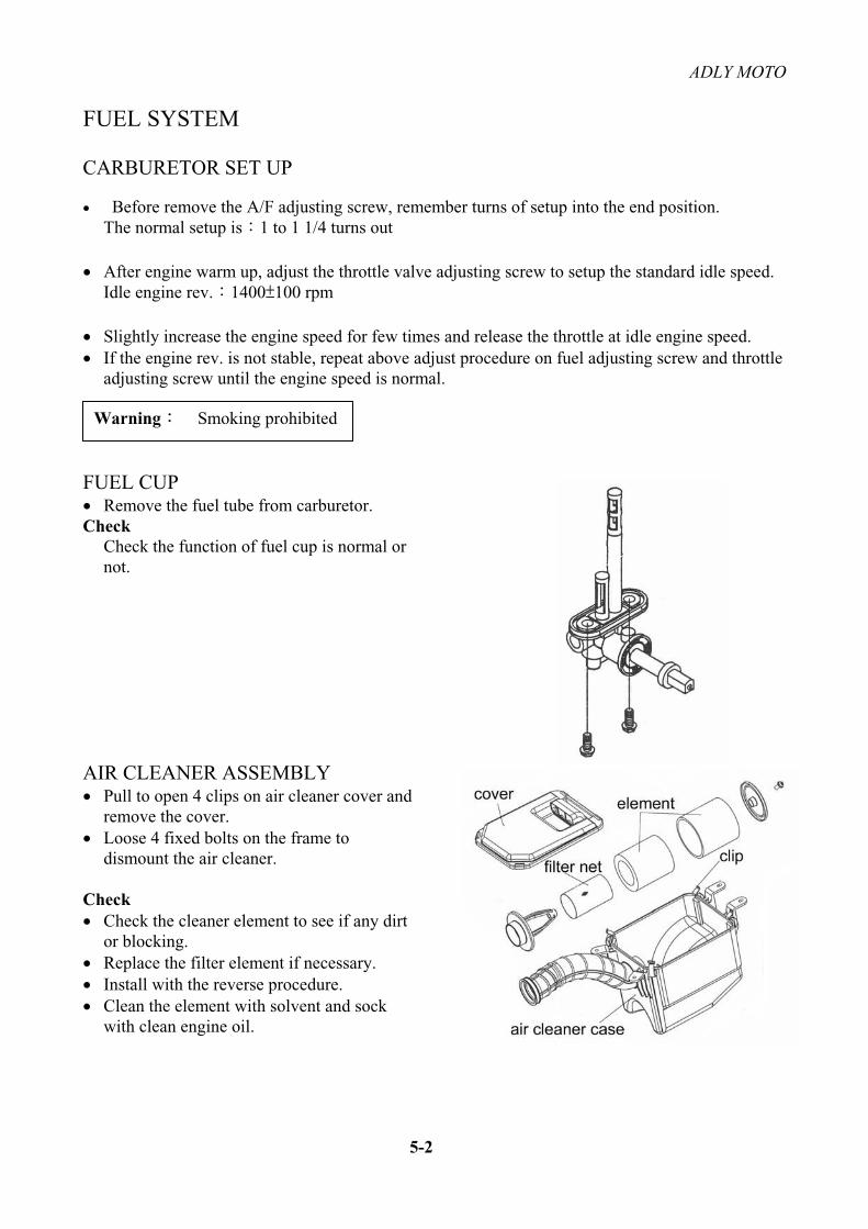
FUEL CUP Remove the fuel tube from carburetor.
CheckCheck the function of fuel cup is normal or not.
AIR CLEANER ASSEMBLY Pull to open 4 clips on air cleaner cover and
remove the cover. Loose 4 fixed bolts on the frame to
dismount the air cleaner.
Check Check the cleaner element to see if any dirt
or blocking. Replace the filter element if necessary. Install with the reverse procedure. Clean the element with solvent and sock
with clean engine oil.
Warning Smoking prohibited

ADLY MOTO
5-3
FUEL SYSTEM
Remove the Carburetor Loose the fuel releasing screw of the carburetor and release the fuel in float chamber. Remove the fuel tube and vacuum (-) pressure tube. Taking off the intake clamp. Taking off the guide pipe clip. Remove the choke cable from carburetor. Remove the throttle cable.
Disassembly of carburetor
Remove the float chamber drain plug, O-ring and accelerator pump cover screws
Remove the accelerator pump cover, diaphragm spring and diaphragm
Remove the float chamber screws, the float chamber and its O-ring
Remove the screw and float pin, then remove the float.

ADLY MOTO
5-4
FUEL SYSTEM
Remove the needle valve
Using a backup wrench on the needle jet holder, unscrew the main jet, then the needle jet holder and nut.
Remove the needle jet
Unscrew and remove the slow jet
Remove the throttle valve cover screws, then open the cover
Remove the throttle valve Warning Be ware not to damage the main jet.
Needle jet
Needle jet

ADLY MOTO
5-5
FUEL SYSTEM
Remove the jet needle Set the cir-clip position to adjust the jet needle.
Remove the seal cover, spring and plunger
Seal coverPlunger

ADLY MOTO
ENGINE REMOVE AND INSTALLATION
ENGINE REMOVAL Remove Engine Drain the engine oil. Remove the seat and the left footpeg
assembly. Remove the body cover assembly. Disconnect the negative battery cable. Remove the fuel tank. Disconnect the crankcase breather tube from
cylinder head cover and on cylinder. Remove the carburetor. Remove the exhaust system. Label and disconnect the following wires:
Spark plug wire Alternator (there-pin connector) Reverse and neutral switches Starter cable Disconnect the reverse cable. Remove the shift pedal. Disconnect the clutch cable from the lifter
arm and detach the cable from the bracket. Remove the drive sprocket cover, remove the
drive sprocket and pull the drive chain back so that it doesn’t interfere with engine removal.
Remove the engine mounting bolts, nuts and brackets at the upper front, upper rear, lower front and lower rear.
Have an assistant help you lift the engine and remove it from the left side.
Slowly lower the engine to a suitable working area. Remove the external oil pipe on cylinder head cover for bigger clearance to remove the engine.
6-1

ADLY MOTO
ENGINE REMOVE AND INSTALLATION
INSTALLATION Mounting the engine and tie-up fixed nuts with standard locking torque.
Locking torque Fixed M10 nuts on bracket 4.0 kg-m
Place a floor jack under the engine. Again, be sure to protect the engine from the jack head with a block of wood. Lift the engine to align the mounting bolt holes, then install the brackets, bolts and nuts.
The remainder of installation is the reverse of the removal steps, with the following additions: a) Use new gaskets at all exhaust pipe connections. b) Adjust the clutch cable and the throttle cable. c) Fill the engine with oil. Run the engine and check for leaks.
Finish mounting the engine; be sure to check the throttle cable tolerance.
Use reversed procedure to setup the parts that has been removed.
NOTEAll cables and wiring has to be set into correct position
6-2
7-0
CYLINDER HEAD, VALVE
TROUBLE DIAGNOSE
Idle Speed not Stable Compression pressure too low Bad adjustment of valve clearance Valves banded or burn Valve timing not correct Damage of valve spring Sealing of valves and seats abnormal Leaking of cylinder head gasket Bottom of cylinder head damaged Wrong installation of spark plug
Valve gap adjustment 0.08 mm
Compression Pressure too high Too much carbon-residue inside
combustion chamber. Emission with White Smoke Valves or valve guide attrition Oil seal on valve attrition Piston ring attrition
Noise Bad adjustment of valve gap Valve burn or spring damaged Camshaft or rock arm attrition Attrition of cam-chain guide comp.

ADLY MOTO
7-1
CYLINDER HEAD / VALVE
Attention of Operation Can be operated when engine installed on vehicle. Must cleaning before operating, avoiding dust enter the engine. Remove the gasket dust stay on joint face. Avoid to use screwdriver harm the joint face when remove the cylinder & cylinder head. Cleaning before check parts, and smear motor oil appointed in sliding face before installing.
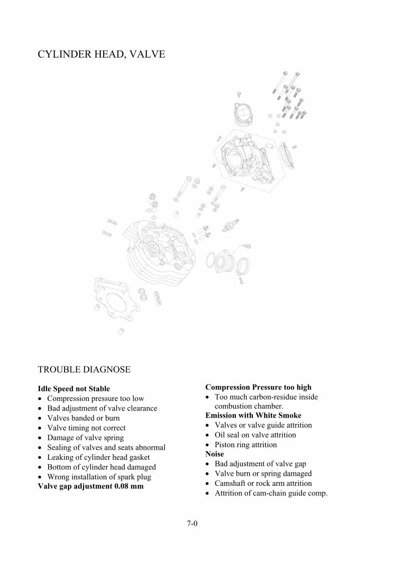
Remove Cylinder Head
5
4
3 2 1
SEQ Operation / Parts Name Q’ty Remarks
12345
Disassembly
Cap nut of exhaust pipe ( 8mm ) Exhaust pipe of front section Exhaust pipe gasket Hex flange bolt Intake manifold assembly
21121
Unscrew the bolts cross-wise for 2~3 times.
WARNING: Don’t knock cooling fin.
Assembly5 1
Operation with sequence in reverse of disassembly.
Tie-up nuts on cylinder head cover 2~3 times.

ADLY MOTO
7-2
CYLINDER HEAD / VALVE
Disassembly the cylinder head
SEQ. Operation / Parts Name Q’ty Remarks
123456789101112131415
Disassembly Spark plug Hex flange bolt Hex flange bolt Hex flange bolt Hex flange bolt Hex flange bolt Hex flange bolt Plain washer Cylinder head cover assembly Hex acorn washer face nut Plain washer Hex socket bolt Dowel pin Cylinder head Cylinder head gasket
133121151462211
6 28
6 52
6 35
6 80
6 115
6 136
6.5 14 1.6
M10 P1.5
10 20 2
10 105 P1.25
8 12
Check the gasket if wear out or damaged
Assembly15 1
Operation with sequence in reverse of disassembly.

ADLY MOTO
7-3
CYLINDER HEAD / VALVE
Remove the camshaft and valve
SEQ. Operation / Parts Name Q’ty Remarks
12345678910
Disassembly
Dowel pin Rocker arm shaft comp. Valve arm rocket assembly Valve cotter Valve spring assembly Inlet/Exhaust valve Valve stem seal Hex flange bolt Camshaft sprocket Camshaft comp
2228444211
The dowel pins are located underneath the cylinder head cover. Using 8mm bolt to pull out the shaft from R side.
38T
Assembly
10 1Operation with sequence in reverse of
disassembly.

ADLY MOTO
7-4
CYLINDER HEAD, VALVE damaged? Check the cam surface to see if it’s wear out
orWorking limit: Replace if IN. cam under 35.57 mm EX. cam under 35.58 mm
Check the camshaft bearings to see if it’s wear out or loose. If it’s loose or damaged then change whole set of camshaft
Check the rock arm and shaft Check rock arm inside diameter
Working Limit: Replace if over 12.04mm
Check the rock arm shaft outside diameter. Working Limit: Replace if under 11.92mm
NoteIf the sliding face of rock arm wear out
then check the cam surface of the cam shaft
Check the gap between rock arm and shaft. Working Limit: Replace if over 0.07 mm
Remove valves Use valve spring holder tool to remove the spring holder, cotter, spring, valve, and seal.
NoteValve spring must use special tool to
disassembly. Parts removed have to place in certain
order, assembly in opposite order.
Valve spring holder tool TLH3-03
special

ADLY MOTO
7-5
CYLINDER HEAD, VALVE
Check cylinder head Check the hole of spark plug and valve guide
to see if it’s damaged.
Check valve spring free length Working limit: Outer spring: Replace under 39.8 mm Inner spring: Replace under 37.8 mm
Check valve and valve guide Check valve to see if it’s burned or banded. Check the movement between valve and
guide is smooth or not.
Valve outside diameter working limit: Replace under 5.45 mm Valve guide inside cylinder head working limit: Replace if over 5.53 mm
Cylinder head assembly Install valve seal, spring seat
Install valve into cylinder head with some lubrication oil on seal and spring seat Install springs, spring holder, cotter and use
special tool to assembly.
Valve spring holder tool TLH3-03
Use rubber hammer hit the valve top for 2 ~ 3 times to have better contact between valve and cotter.
NoteInstall new valve seal after removed.
NoteMust use the special tool.Valve cotter sharp edge face toward
cylinder head bottom.
special

ADLY MOTO
7-6
CYLINDER HEAD, VALVE
Camshaft adjustment After install the cylinder head, it’s necessary
to setup the camshaft timing. Before put the timing chain on cam sprocket,
turn the “T” mark on ACG flywheel aim at the crankcase sign.

ADLY MOTO
8-1
CYLINDER, PISTON
TROUBLE DIAGNOSE Low compression pressure Piston ring wear-out, burn, or broken Cylinder, piston wear out or damaged.
Compression pressure too high Piston or combustion chamber stocks
with carbon material. Avoid to harm the cylinder inner surface and
piston face.
Exhaust with white smoke Piston ring wear-out, burn, or broken Cylinder, piston wear out or damaged.
Piston noise Piston, cylinder, or piston ring damaged. Piston pin and piston wear out
Disassembly of Cylinder / Piston
Operation / Parts Name Q’ty Remarks
12345
Disassembly Cylinder Cylinder and gasket Hex flange bolt Cylinder Oil ring Cylinder gasket Dowel pin
21112
WARNING: Don’t knock the cooling fin.
Clean the gasket stick on crank case. Replace if necessary Replace if deformed
6789
Disassembly Piston Piston pin clip Piston pin Piston ring set Piston
2111
WARNING: Don’t knock the piston when remove the pin.
Check the piston, piston pin, and piston rings. Clean the carbon residual on ring and ditch on piston. Beware not to break or damage the piston rings.
Assembly9 1
Operation with sequence in reverse of disassembly.

ADLY MOTO
8-2
CYLINDER, PISTON
Cam chain tensioner Removal Loosen the cam chain tensioner sealing bolt
and washer. The cam chain tensioner lifter shaft must be
retracted and locked into place before removing the tensioner.
Remove the tensioner mounting bolts and detach the tensioer from the cylinder block.
Clean all old gasket material from the tensioner body and from its mating surface on the cylinder block.
Installation Lubricate the friction surfaces of the
components with moly-based grease. Install a new tensioner gasket on the
cylinder. Cut the cable tie and remove the coat hanger
wire. Install the tensioner sealing bolt and a new
sealing washer and tighten the sealing bolt to toque.
Disassembly of Piston The piston should have an IN mark on its
crown that goes toward the intake side of the engine.

ADLY MOTO
8-3
CYLINDER, PISTON
Wear eye protection and pry the cir-clip out of its groove with a pointed tool.
Push the piston pin part-way out, then pull it the rest of the way.
Inspection of Piston Remove the top and second piston rings.
Remove the upper oil ring side rail and expander, then remove the lower side rail.
Warning Be-ware not to scratch the piston during
ring removal.

ADLY MOTO
8-4
CYLINDER, PISTON
Measure the piston ring-to-groove clearance with a feeler gauge.
Working limit: Top ring: replace above 0.11mm 2nd ring: replace above 0.09 mm
Take-off piston rings and put into the bottom of cylinder.
NoteUse piston to press the ring into cylinder.
Measure the opening gap of the piston ring when pressed into cylinder.
Working limit: Top ring: replace above 0.5mm 2nd ring: replace above 0.5mm
Measure the hole of the piston pin. Working limit: Replace if inside diameter is over 17.04 mm
Measure outside diameter of piston pin. Working limit: Replace if under 16.96 mm
ADLY MOTO
8-5
CYLINDER, PISTON
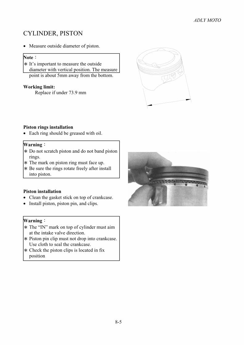
Measure outside diameter of piston.
NoteIt’s important to measure the outside diameter with vertical position. The measure point is about 5mm away from the bottom.
Working limit: Replace if under 73.9 mm
Piston rings installation Each ring should be greased with oil.
WarningDo not scratch piston and do not band piston rings.The mark on piston ring must face up. Be sure the rings rotate freely after install into piston.
Piston installation Clean the gasket stick on top of crankcase. Install piston, piston pin, and clips.
WarningThe “IN” mark on top of cylinder must aim at the intake valve direction. Piston pin clip must not drop into crankcase. Use cloth to seal the crankcase. Check the piston clips is located in fix position

ADLY MOTO
8-6
CYLINDER, PISTON
Cylinder Installation Put the dowel pins and gasket on top of
crankcase.
Cylinder inside surface, piston, and piston rings must be greased with oil. Beware of the pressure from piston ring
when install into cylinder.
WarningBe careful not to damage or band the piston ring.The opening section of piston rings should not be the same with piston pin and set into 120° to each other.
Fit the cylinder into correct position.

9-1
CLUTCH, STARTING SYSTEM
Trouble Diagnose
Clutch sliding at accelerating Clutch plate wearing. Resilience of spring is fatigue. Without the free play.
L. side level is too tight Clutch wire is damage. Connecting-rod institution is damage.
Gear shafting is difficult Clutch gap is not setup properly. Clutch plate banded.
Clutch plate not opening The free play is too big. Clutch plate banded.
Disassembly of right crankcase cover and clutch lever
SEQ Operation / Parts name Q’ty Remarks
12345678910
DisassemblyHex flange bolt R. crankcase cover R. crankcase cover gasket Dowel pin Clutch lifter guide pin Split spring pin Clutch lever comp. Oil seal Needle bearing Clutch lever spring
12112111121
Use rubber hammer slightly hit the cover from side way for easier removal.
Replace new gasket after disassembly. Beware not to damage the pin.
Clean the plate if there is any grimy or dusty material.
Beware not to damage the spring.
Assembly10 1
Operation with sequence in reverse of disassembly.

ADLY MOTO
9-2
CLUTCH, STARTING SYSTEM
Disassembly of Clutch system
SEQ Operation / Parts name Q’ty Remarks
123456789101112131415
Disassembly
Hex bolts Clutch lifter plate Cir clip Needle bearing Thrust washer Clutch spring Lock nut Disc spring washer Clutch center Clutch friction disk Clutch plate Clutch pressure plate Plain washer Clutch cover comp assembly Oil bush
411114111651111
Beware not to damage the washer, replace if damaged. Open the lock section on the nut before removal. Band the washer open from the spanner nut first.
Check the friction plate wear out or not.
Assembly15 1
Operation with sequence in reverse of disassembly.
ADLY MOTO
9-3
CLUTCH, STARTING SYSTEM
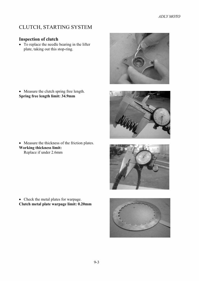
Inspection of clutch To replace the needle bearing in the lifter
plate, taking out this stop-ring.
Measure the clutch spring free length. Spring free length limit: 34.9mm
Measure the thickness of the friction plates. Working thickness limit: Replace if under 2.6mm
Check the metal plates for warpage. Clutch metal plate warpage limit: 0.20mm

ADLY MOTO
9-4
CLUTCH, STARTING SYSTEM
Disassembly of Starter Reduction Gear and Starting Motor
SEQ Operation / Parts name Q’ty Remarks
12345678
Disassembly
Hex flange bolt Reduction cover Starter gear cover gasket Dowel pin Starter reduction gear comp. Starter reduction gear shaft Hex flange bolt Starter motor assembly
61121121
M6×32, M6×25
Do not damage the dowel pins
M6×25
Assembly8 1 Operation with sequence in reverse of
disassembly.

ADLY MOTO
9-5
CLUTCH, STARTING SYSTEM
Disassembly of Starter Gear and Generator
SEQ Operation / Parts name Q’ty Remarks
12345678910
Disassembly
Hex flange bolt L. crankcase cover L cover gasket Dowel pin External cir-clip Starter gear Starter reduction gear Hex socket bolt Hex socket bolt Stator comp.
12112211231
M6×20
STW-15
M5 14
M6 30
Assembly10 1 Operation with sequence in reverse of
disassembly.

ADLY MOTO
9-6
CLUTCH AND STARTING SYSTEM
Disassembly of Starter Driven Gear and Starter Clutch assembly
SEQ Operation / Parts name Q’ty Remarks
12345678910
Disassembly
Hex flange bolt Plain washer Generator flywheel Star socket bolt Starting clutch outer comp. Roller assembly Starter clutch assembly Starter driven gear comp. Needle bearing Plain washer
1116111111
M12×45When pull out the flywheel, beware not to lost the
semi-cycle key on crankshaft. Use special tool (TLH3-02) to pull out the
flywheel Start socket bolt M6×20Replace starter clutch set if the roller is damage.
26 31 2426.5 40 2.5
Assembly10 1 Operation with sequence in reverse of
disassembly.
ADLY MOTO
9-7
CLUTCH, STARTING SYSTEM
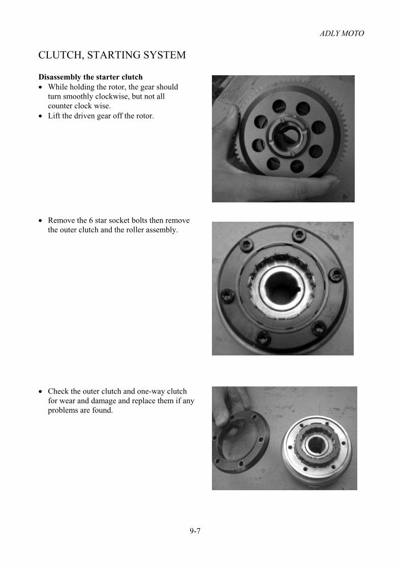
Disassembly the starter clutch While holding the rotor, the gear should
turn smoothly clockwise, but not all counter clock wise.
Lift the driven gear off the rotor.
Remove the 6 star socket bolts then remove the outer clutch and the roller assembly.
Check the outer clutch and one-way clutch for wear and damage and replace them if any problems are found.

ADLY MOTO
10-1
CRANKCASE, CRANKSHAFT
TROUBLE DIAGNOSE Engine noise Loose of crankshaft bearings. Loose of bearings inside crankshaft connecting rod.
DISASSEMBLY OF THE CRANKCASE
SEQ Parts Name Q’ty Remarks
123456789
101112131415
Disassembly
Hex flange bolt Breather tube clamp Clutch wire receiver Oil filter screen Hex socket flange bolt Breather plate Breather plate gasket Left crankcase Crankcase gasket Right crankcase Dowel pin Hex flange bolt Plain washer Stud bolt Stud bolt
1411111111121122
M6 35, M6 45, M6 65
M6 12
Use rubber hammer slightly hit the gear to remove the crankcase.
Scratch off the gasket which between crankcases and use new gasket after disassembly.
Do not damage the crankcase surrounding edge. Check the oil seal is attrition or not. M12 15
12.5 20 2The stud bolts are not necessary to remove unless it’s
banded or defect
Assembly15 1 Operation with sequence in reverse of disassembly.

ADLY MOTO
10-2
CRANKCASE, CRANKSHAFT
DISASSEMBLY OF THE TRANSMISSION GEAR
SEQ Parts Name Q’ty Remarks
123456789
Disassembly
Hex socket bolt Bearing setting plate Main shaft assembly Counter shaft assembly Reverse idle gear shaft Thrust washer Reverse idle gear Reverse idle gear bush Thrust washer
111212111
The gear assembly should pull out at the same time with drum shaft assembly.
Beware keep the washer and cir-clip in original order.
The ball and needle bearings are located on crankcase. Check the bearing is functioning well or not.
Be-ware of the gear set sequence and assembly direction.
Assembly9 1 Operation with sequence in reverse of
disassembly.

ADLY MOTO
10-3
CRANKCASE, CRANKSHAFT
DISASSEMBLY OF THE GEAR SHAFT MECHANISM
SEQ. Parts Name Q’ty Remarks
123456789
101112131415161718192021
DisassemblyGear shift arm assembly Shifter collar Hex flange bolt Guide plate Rotor assembly Bushing Bearing holder plate Shift pin Shift drum center Hex flange bolt Gear shift drum stopper assembly Hex socket bolt Hex washer face bolt Neutral switch rotor comp. Reverse stopper cam comp. Hex flange bolt Reverse shift stopper comp. Gear shift fork assembly Gear shift spindle comp Hex socket bolt Gear shift drum assembly
111111211112111212111
Parts from sequence 1 to 11 are removed during previous L crankcase disassembly.
Parts from sequence 12 to 17 are removed during previous R crankcase disassembly.
Check the tolerance between the forks and drum.
Assembly21 1
Operation with sequence in reverse of disassembly.
Apply oil during assembly.

ADLY MOTO
10-4
CRANKCASE DISASSEMBLY
GEAR SHIFT MECHANISM Check the small spring locates on the
gearshift arm to see if it’s too loose or not. Check the stopper plate is loose or not. Check the roller guide.
Working diameter limit: Replace if under 5.7mm
Check the inside diameter of the forks.
Working diameter limit: Replace if over 13.04mm
Check the outside diameter of the forks.
Working diameter limit: Replace if over 12.96mm
Check the fork ear thickness applied to gear shaft area.
Working diameter limit: Replace if under 4.50mm
Check the shift drum grooves for wear, especially at the points.
Center gear shift fork R/L gear shift fork

ADLY MOTO
10-5
CRANKCASE, CRANKSHAFT
REMOVE OF THE CRANK SHAFT
SEQ Parts Name Q’ty Remarks
123456
Disassembly
Shaft comp assembly Crank shaft assembly Radial ball bearing Semi-cycle key Radial ball bearing Radial ball bearing
111111
The crankshaft assembly normally is not for disassembly. It will generate more problems if the L/R cranks are disassembled.
The semi-cycle key normally was took out when disassembly the flywheel. Beware keep it in certain place to avoid lost.
Assembly6 1 Operation with sequence in reverse of
disassembly.
ADLY MOTO
10-6
CRANKCASE, CRANKSHAFT
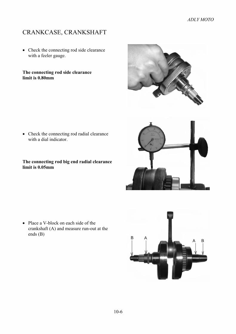
Check the connecting rod side clearance with a feeler gauge.
The connecting rod side clearance limit is 0.80mm
Check the connecting rod radial clearance with a dial indicator.
The connecting rod big end radial clearance limit is 0.05mm
Place a V-block on each side of the crankshaft (A) and measure run-out at the ends (B)

ADLY MOTO
10-7
CRANKCASE, CRANKSHAFT
Check the connecting rod.
Working diameter limit: Replace if over 17.10mm
Check the balancer gear and bearing journals for wear or damage.
Use a special tool (TLH3-01) to pull the crankshaft and push the left crankcase onto the crankshaft.
ADLY MOTO
11-1
FRONT WHEEL / SUSPENSION / STEERING
Attention of Operation
Remove the body cover and support the frame body bottom before remove the front wheel, don’t
invert the front wheel when front wheel depart ground.
Diagnosis of Trouble
Heavy steering movement
Air pressure too low of front tire.
Rim radial ball bearing broken.
Brake efficiency abnormal
Brake lining wear-out.
Brake pads adjust not correct or wear out.
Brake drum wear-out.
Tire wear-out.
Steering handle not straight
Loose, not correct adjustment or damaged,
right (or left) link Assembly.
Steering shaft bended.
Suspension arm, knuckle damaged.
Front wheel shaking or deviation
Front rim defected.
Loose or damaged of front rim bearings.
Tire defect.
Bad adjustment or defected of the right (or
left) link assembly.
Bad adjustment or defected of the right (or
left) knuckle.

ADLY MOTO
11-2
FRONT WHEEL / SUSPENSION / STEERING
Disassembly of Front Wheels
SEQ Operation / Parts name Q’ty Remarks
1234567891011 121314
Disassembly front wheels (L/R)
Rubber cover Cotter pin Scotch nut Plain washer Wheel nut Front shaft hub Front rim Front tire CollarCollarOil seal Radial ball bearing Hex socket bolt Brake disc
22228222224482
M1818 40 4.5M10 15
29.3 43.6 4.56004ZZCM/2A-TO
Diameter=164mm
Assembly wheels Assembling with sequence in reverse of
disassembly.
WARNING:Change the R/L bearing set if necessary.

ADLY MOTO
11-3
FRONT WHEEL / SUSPENSION / STEERING
Disassembly of Suspension Arm
Operation / Parts name Q’ty Remarks
123456789
Disassembly (L/R)
Hex flange lock nut Plain washer Hex washer face bolt L/R down suspension arm Hex flange bolt Front cushion assembly Cotter pin Plain washer Scotch nut
221212222
M1010 20 210 55
M10 403 3212 22 2M12
Assembly 9 1 Assembling with sequence in reverse of
disassembly.

ADLY MOTO
11-4
FRONT WHEEL / SUSPENSION / STEERING
Disassembly of Steering Shaft Assembly
SEQ Operation / Parts name Q’ty Remarks
1234567891011 12131415
Disassembly steering shaft Ass’y
Cotter pin Nylon nut Oil seal Steering shaft bushing Internal cir-clip Oil seal Cotter pin Scotch nut Plain washer Tie-rod assembly Hex socket bolt Handle bar clamp Handle bar Nylon nut Plain washer
111111222242122
M1010 20 2
6 25
M10 P1.25 10 22 2.5

ADLY MOTO
11-5
FRONT WHEEL / SUSPENSION / STEERING
Disassembly of Steering Shaft Assembly
SEQ Operation / Parts name Q’ty Remarks
161718192021
Disassembly knuckles
Handle bar bottom clamp Steering shaft assembly Hex washer face bolt Bracket Steering shaft holder Holder spacer collar
212122
10 65
Assembly steering shaft Ass’y 21
Assembling with sequence in reverse of disassembly.
WARNING: Adjusting gap of throttle.

ADLY MOTO
12-1
REAR WHEEL / SUSPENSION / BRAKES
Diagnosis of Troubles Rear wheel shaking or deviation
The shape of rear rim damaged.
Rear wheel axle damaged.
Swing arm sub Ass’y damaged
Rear rim bearing defected.
Rear suspension too soft
Spring too soft or adjust not correct.
Brake efficiency abnormal
Brake lining wear-out.
Brake pads adjust not correct or wear out.
Brake drum wear-out.
Tire wear-out.
Assembly/Disassembly Rear Wheel
SEQ Operation / Parts name Q’ty Remarks
12345678
Disassembly Wheels
Rubber cover Cotter pin 3*32 Scotch nut Plate washer 18*40*4.5 Hex washer face bolt 10*20 Shaft connector Rear rim Rear tire
22224222
Assembly 8 1
Assembling with sequence in reverse of disassembly.

ADLY MOTO
12-2
REAR WHEEL / SUSPENSION / BRAKES
Disassembly of Parking Brake and Rear Disc
SEQ Operation / Parts name Q’ty Remarks
1234567891011 1213
Disassembly parking brake
Rubber cover Cotter pin Scotch nut Plain washer Rear wheel assembly Hex nut Hex socket bolt Rear brake panel connector Rear brake disk Hex washer face bolt Rear brake caliper assembly Parking brake cable Right lever assembly
1111123112111
M8 18
10 28
Assembly 13 1
Assembling with sequence in reverse of disassembly.

ADLY MOTO
12-3
REAR WHEEL / SUSPENSION / BRAKES
Disassembly of Brake System
SEQ Operation / Parts name Q’ty Remarks
1234567891011 121314151617
Disassembly brake system
Cotter pin Fix pin External cir-clip Plain washer Oil ring Brake pedal comp Return spring Oil tube fixing bolt Hex flange bolt Hex washer face bolt Rear master cylinder sub assembly Copper plain washer Hex washer face bolt Brake hose hex bolt Rear brake hose Hex washer face bolt Rear brake caliper assembly
11112111211953121
2 20
STW-16
10 35M8 256 1510.2 15 16 1210 22
10 28

ADLY MOTO
12-4
REAR WHEEL / SUSPENSION / BRAKES
Disassembly of Brake System
SEQ Operation / Parts name Q’ty Remarks
18192021
Disassembly brake system
Hex flange bolt Front brake caliper assembly Hex flange bolt Back hose
4211
M8 22
M6 20
Assembly 21 1
Assembling with sequence in reverse of disassembly.

ADLY MOTO
12-5
REAR WHEEL / SUSPENSION / BRAKES
Disassembly / Assembly of Rear sprocket Assembly
SEQ Operation / Parts name Q’ty Remarks
1234567891011 12131415
Disassembly Rear Brake
Hex flange bolt M8*15 Chain protect cover Hex flange bolt 6*30 Front chain protect Drive chain guide Hex bolt 6*10 Drive sprocket fixing plate Drive sprocket assembly Drive chain assembly Nylon nut M10*P1.25 Hex socket flat head bolt M10*27Drive sprocket Rear sprocket flange External cir-clip Rear wheel axle
312112111441111
Assembly 15 1
Assembly with sequence in reverse of disassembly.

ADLY MOTO
12-6
REAR WHEEL / SUSPENSION / BRAKES
Disassembly / Assembly of Swing arm sub Assembly & Rear Cushion
SEQ Operation / Parts name Q’ty Remarks 1
23456789
1011 12131415
161718
Rear wheel axle
Disassembly rear cushion Ass’y Nylon nut Hex flange bolt Rear axle holder Hex flange bolt Hex flange bolt Nylon insert lock nut Plain washer Rear cushion assembly
Disassembly swing arm sub Ass’yNylon nut Plain washer Swing arm seal cover Swing arm bolt CollarSwing arm sub assembly
Hex flange bolt BushingRubber bushing
1
11111221
112111221
Assembly Rear cushion 9 2 Swing arm sub 15
Assembly with sequence in reverse of disassembly.

ADLY MOTO
13-1
ELECTRICAL DEVICE
Attention of Operation
WARNING
Battery electrolyte contains sulfuric acid, which can cause severe burns. Avoid contact of skin,
eyes, or clothing
When sulfuric acid water spill into clothing will stick to skin. Take off the clothing and flush
with water.
Battery can be charged and discharged. Without charging, the battery will have less lifetime.
If the battery have short circuit inside, both terminal will not have voltage existed. Besides, the
regulator rectifier lost the function and shorter lifetime.
If the battery stay too long without use, it will lost power and have less capacity. The battery
need to charge each 2~3 months.
After fill up the electrolyte, the new battery will generate voltage. It’s necessary to recharge if
the voltage is low. It’s necessary to leave the battery for more than 20 minutes before sealing
the cap. It will increase the lifetime of new battery if recharged before installed.
Do not unplug the electrical components from wire hardness when the current is working. This
will cause too high of voltage and damage other compounds such as rectifier, light bulbs…etc.
Turn off the main switch to OFF before the operation.
The Maintenance Free battery does not need to refill electrolyte or water.
All charge system needs to be installed before check.
Do not use quick charge unless it’s in urgent.
The battery needs to be taking out from vehicle when doing charge work.
When checking the voltage, must use the electrical meter.
Diagnosis of troubles No Electrical Power
Over discharged of the battery
Wire hardness did not connected to
the battery
Fuse broken
Main switch defect
Low Voltage
Battery charges insufficient
Bad connection
Regulator rectifier defect
No Continues Current
Bad contact of battery with main wire
hardness
Bad connection of charge system
Bad contact of the lighting system
cause short circuit
Charge System no function
Bad connection of the wire hardness
connectors
Main wire hardness broken or
short-circuit
Regulator rectifier defect
AC Generator defect
Fuse broken
ADLY MOTO
13-2
ELECTRICAL DEVICE
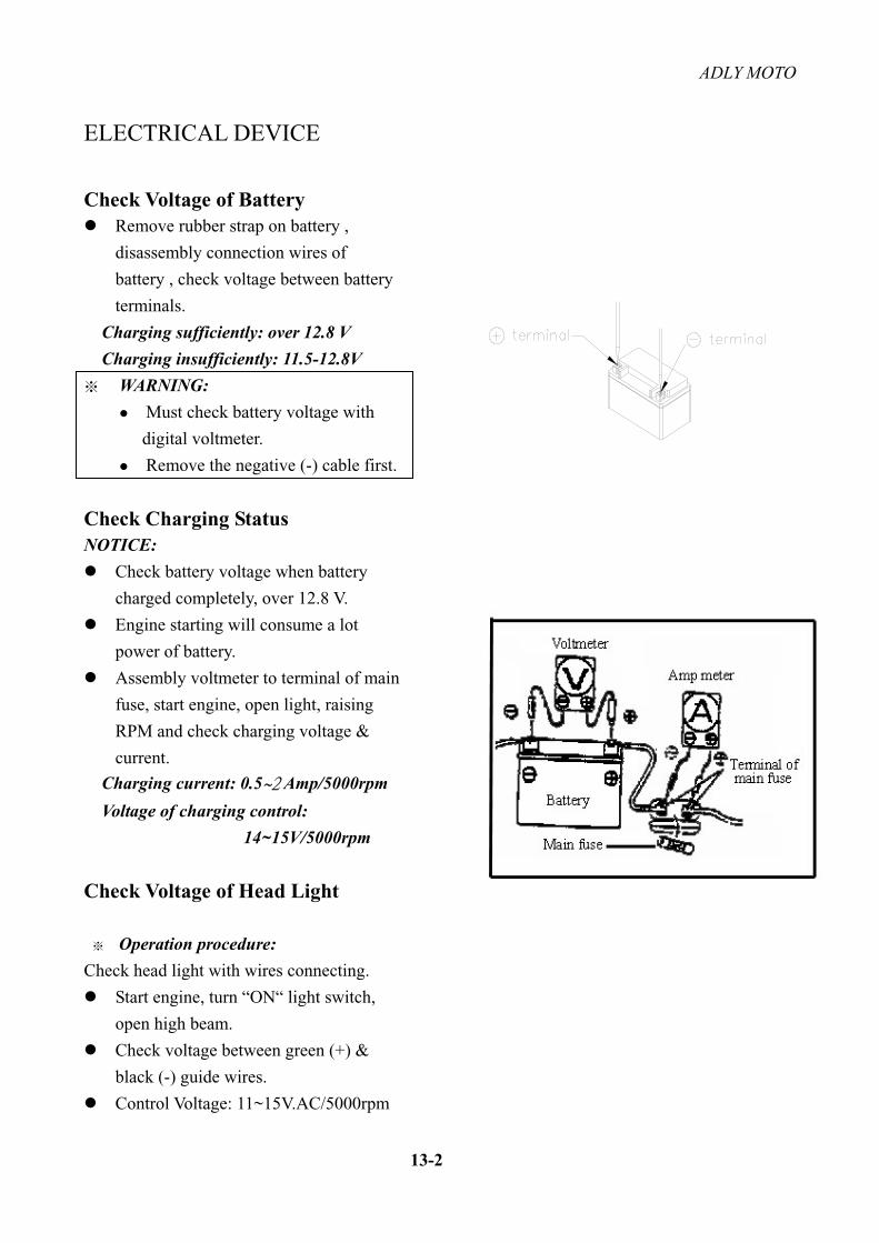
Check Voltage of Battery Remove rubber strap on battery ,
disassembly connection wires of
battery , check voltage between battery
terminals.
Charging sufficiently: over 12.8 V
Charging insufficiently: 11.5-12.8V
WARNING:
Must check battery voltage with
digital voltmeter.
Remove the negative (-) cable first.
Check Charging Status NOTICE:
Check battery voltage when battery
charged completely, over 12.8 V.
Engine starting will consume a lot
power of battery.
Assembly voltmeter to terminal of main
fuse, start engine, open light, raising
RPM and check charging voltage &
current.
Charging current: 0.5 Amp/5000rpm
Voltage of charging control:
14~15V/5000rpm
Check Voltage of Head Light
Operation procedure:
Check head light with wires connecting.
Start engine, turn “ON“ light switch,
open high beam.
Check voltage between green (+) &
black (-) guide wires.
Control Voltage: 11~15V.AC/5000rpm
ADLY MOTO
13-3
ELECTRICAL DEVICE
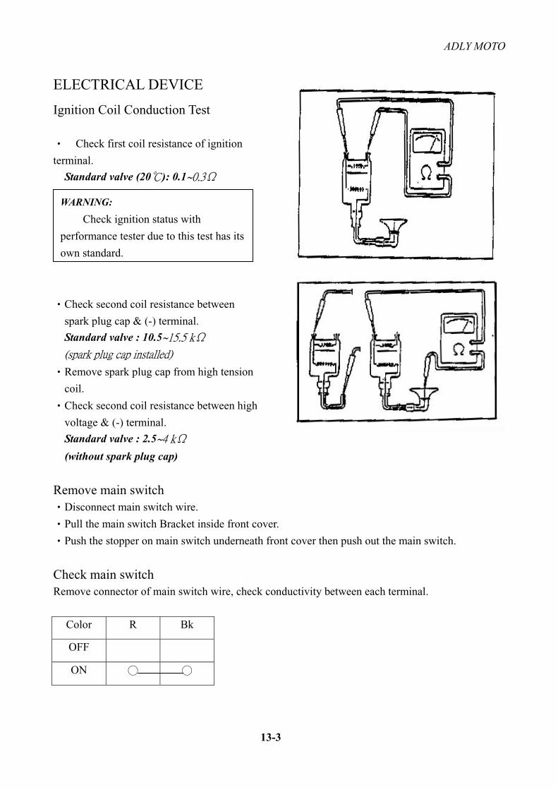
Ignition Coil Conduction Test
Check first coil resistance of ignition
terminal.
Standard valve (20 ): 0.1
Check second coil resistance between
spark plug cap & (-) terminal.
Standard valve : 10.5
Remove spark plug cap from high tension
coil.
Check second coil resistance between high
voltage & (-) terminal.
Standard valve : 2.5
(without spark plug cap)
Remove main switch Disconnect main switch wire.
Pull the main switch Bracket inside front cover.
Push the stopper on main switch underneath front cover then push out the main switch.
Check main switchRemove connector of main switch wire, check conductivity between each terminal.
Color R Bk
OFF
ON
WARNING:
Check ignition status with
performance tester due to this test has its
own standard.

ADLY MOTO
13-4
ELECTRICAL DEVICE
Head light and position light
Signal light switch
Engine stop switch
Exchange of Bulbs
Head light bulb
Remove handle bar and front cover
Press down the bulb base and turn left to change
head light bulb.
Start switch
Horn switch
