administration guide - planet › storage › products › 48912 › administrati… · protocol...
TRANSCRIPT

1
Document Version: 1.1 Software Version: 1.3.xxx.xxx Release Date: 2016/01/31
Administration Guide

2
Table of Contents Chapter 1. Overview ....................................................................................................................... 3
Chapter 2. Auto-Provisioning – For massive deployment of phones ....................................... 4
2.1 Introduction ........................................................................................................................... 4
2.2 Provision Methods ................................................................................................................ 5
2.2.1 Plug and Play (PnP) Server ........................................................................................ 6
2.2.2 DHCP Options ............................................................................................................ 7
2.2.3 Static Provisioning Server .......................................................................................... 9
2.3 Server Setup ....................................................................................................................... 10
2.3.1 Configure a TFTP server .......................................................................................... 10
2.3.2 Configure an FTP server .......................................................................................... 12
2.3.3 Configure an HTTP server ........................................................................................ 14
2.3.4 Configure a DHCP server ......................................................................................... 16
Chapter 3. Quality of Service (QoS) – Enhance the communication quality .......................... 23
3.1 VLAN ................................................................................................................................... 23
3.1.1 Introduction ............................................................................................................... 23
3.1.2 Configure VLAN for VoIP Priority ............................................................................. 24
3.1.3 VLAN CoS (Class of Service) ................................................................................... 26
3.2 LLDP ................................................................................................................................... 26
3.3 DSCP .................................................................................................................................. 27
Chapter 4. Action URL and Active URI – Collaborative working environment through Computer
Telephony Integration (CTI) ................................................................................................................. 29
4.1 Introduction ......................................................................................................................... 29
4.2 Action URL configuration .................................................................................................... 31
Chapter 5. Active URI ................................................................................................................... 33
5.1 Introduction ......................................................................................................................... 33
5.2 Active URI configuration ..................................................................................................... 34
5.3 Daylight Saving Time Settings ............................................................................................ 35
Chapter 6. Traversing NAT ........................................................................................................... 36
6.1 Introduction ......................................................................................................................... 36
6.2 STUN .................................................................................................................................. 36
6.3 Rport ................................................................................................................................... 38
3
CHAPTER 1. OVERVIEW The target audiences of this document are IT administrators, technical professionals, and technical
supporters. This document assumes the audiences have preliminary knowledge about Internet, network
infrastructures and protocols, Voice over IP technologies, etc. Hence, this document will not explain
particular protocols or standards in detail.
The administration guide is to help IT administrators to manage massive phones in an enterprise or small
office environment. An IT administrator may follow the guidance in this document to set up a provisioning
server to massively configure tens, hundreds, or thousands of phones through the network with
pre-scripted configuration files. Meanwhile, the IT administrators can learn how to enhance the quality of
service (QoS) , or set up a local upgrade server, etc., from this document.

4
CHAPTER 2. AUTO-PROVISIONING – FOR
MASSIVE DEPLOYMENT OF
PHONES
2.1 Introduction
This section provides instructions on how IP phones interoperate with provisioning server for auto
provisioning, and shows you four major tasks to provision the phones. It will help users who are not familiar
with auto provisioning to understand this process more easily and quickly.
There are 4 configuration files both of which are CFG formatted that the phone will try to download from
the server during provisioning.
a. Common CFG file
b. MAC-oriented CFG file
c. Custom-named CFG file
d. ID-oriented CFG file
The Common CFG file will be effectual for all the phones of the right model. A common CFG file has a
fixed name for each model,The names of the Common CFG file for each model are:
VIP-1120PT: f0VIP-1120PThw1.100.cfg
VIP-2140PT: f0VIP-2140PThw1.100.cfg
The common config file is very helpful for taking Auto Provision deployment to mass terminals. For
example, if you would like to update firmware for 1000 terminals of VIP-2140PT automatically, you will just
need a common config file of f0VIP-2140PThw1.100.cfg) containing firmware parameters with
deployment, then put it on the appropriate server which the configured Auto-Provison process used.
The device config file named after MAC address is just effective for the terminal with
the corresponding MAC address. Its name is the MAC address to remove connectors. For example, the
MAC address of VIP-2140PT is "00: 30: 4f: 11: 3a: f8", so the config file name is "00304f113af8.cfg".

5
The custom-named config file means that users are able to customize its name, For example, user names
a device’s config file name as "name.cfg", then the phone will go to request and download the common
config file and name.cfg from the relevant server.
Sip PnP and DHCP Option can specify the config file name according to the URL, such as
http:// user: [email protected]/name.cfg or http:// user: [email protected]/$input.cfg. The
second method is to let the user enter a file name via the LCD. If you do not
specify http:// user: [email protected] or http:// user: [email protected] $ mac.cfg , it will be
named after Mac address.
2.2 Provision Methods
PLANET IP phones support obtaining the provisioning server address in the following ways:
Plug and Play (PnP) Server
DHCP Options
Static Provisioning Server
The priority of obtaining the provisioning server address is as follows:
PnP Server --> DHCP Options --> Static Provisioning Server.
You can find the configuration in the Web / System / Auto provision.

6
2.2.1 Plug and Play (PnP) Server
As shown:
Enable PnP: whether to start SIP PnP
PnP Server: pnp server address
PnP Port: pnp server port number
PnP Transport: Transport Protocol
PnP Interval: time interval polling to check the time interval between two requests
Restart the phone after setting. It will send the subscribe package to the pnp server, then the server
returns the notify package with URL. The phone parses URL after receiving it.
If you start the PnP server for push deployment, it will periodically send SUBSCRIBE message to the
server after the terminal starts. Take VIP-2140PT for example, the format of Message Header of SIP
SUBSCRIBE message is as follows.
Via: SIP/2.0/UDP 192.168.1.45:5060;branch=z9hG4bK3102710241234624733
From: <sip:[email protected]>
To: <sip:[email protected]>
Call-ID: [email protected]
CSeq: 1 SUBSCRIBE
Contact: <sip:192.168.1.45:5060>
Max-Forwards: 70
User-Agent: PLANET VIP-2140PT
Expires: 0
Event:ua-profile;profile-type="device";vendor="PLANET";model="VIP-2140PT";version="2.0.3.2991"
Accept: application/url
Content-Length: 0
Any SIP servers compatible with the particular message server will respond and send back a SIP
NOTIFY message including the server URL of Auto Provision. The Message Header of SIP NOTIFY
message is as follows:

7
Via: SIP/2.0 / [transport] [local_ip]: [local_port]; branch = [branch]
From: <sip:MAC= 00304fa9994a192.168.1.169>
To: <sip:MAC= 00304fa9994a192.168.1.169>
Call-ID: [email protected]
CSeq: 3 NOTIFY
Max-Forwards: 70
Content-Type: application / url
Subscription-State: terminated; reason = timeout
Event: ua-profile; profile-type = "device"; vendor = "PLANET"; model = "VIP-2140PT"; version =
"2.0.3.2991"
Content-Length: 29
http://192.168.1.118/ $ mac.cfg
http://192.168.1.118/$mac.cfg in the NOTIFY message is the URL of the config file to be downloaded.
Note:
PnP mechanism can support two forms of $mac and $input to get the config file, as well as server
username and password authentication.
2.2.2 DHCP Options
WAN Mode of the phone must be DHCP to use DHCP Option.
There are four options available for DHCP Option: DHCP option 66, DHCP option 43, Custom
DHCP Option and DHCP Option Disable.
Custom DHCP Option’s setting range is 128~254. DHCP Option Disable
means closing DHCP Option.
Restart the phone or wait for a renewal of DHCP server after setting, then the phone will request for
option information from the DHCP server. If the server replies the option information you requested, you
will see the corresponding option information from the capture package replied from the server. Filter
“bootp” and view the ACK package to get the URL which the phone will parse.
When obtaining an application parameter of Auto Provision through DHCP Option mode, the user can
optionally choose one option. For example, If DHCP option 43 is selected, it will have the following field
values in the “DHCP discover message” and “DHCP request message” which terminal sends to the
server.
Option: (t=55,l=7) Parameter Request List
Option: (55) Parameter Request List
Length: 7

8
Value: 011c0302042b06
1 = Subnet Mask
28 = Broadcast Address
43 = Vendor-Specific Information
It will have the following field values in the “DHCP offer message” and “DHCP ACK message” which
the server sends to the terminal. Option: (t=43,l=29) Vendor-Specific Information
Option: (43) Vendor-Specific Information
Length: 29
Value: 746674703a2f2f3139322e3136382e312e3131382f246d61...
“Value” in “Option: (t=43, l=29) Vendor-Specific Information” is the hexadecimal form of the URL
which is the path to download the config file. The Value is http://192.168.1.118/$mac.cfg.
PLANET terminal supports $mac replacement. The value of the URL can be http://ip/$mac.cfg or
http://ip/mac.cfg?mac=$mac.cfg
“DHCP option 66” and “DHCP custom option” application parameters are similar to the DHCP option
43 above.
Note:
PLANET devices also support URL form of http://ip/$input.cfg. If the “Value” in the above “Option: (t =
43, l = 29) Vendor-Specific Information” is http://192.168.1.118/$input.cfg, the phone will pop up a dialog
box of inputting devices’ corresponding configuration ID values. The ID value is assigned by the
administrator. After entering the devices’ corresponding configuration ID values, the devices will
automatically download the config file of the corresponding ID from the server. PLANET devices support
$input replacement simultaneously. The value of the URL can be http://ip/$input.cfg or
http://ip/input.cfg?input=$input.cfg.
Some HTTP/HTTPS/FTP servers require authentication of username and password, then PLANET
devices have two methods for this. Firstly, you can add username and password in the URL, for example,
http://username:passwd@ip/$mac.cfg. Secondly, for URL without username and password, the devices
will pop-up a dialog box to request user to enter username and password for authentication.
Option 66:

9
Option 43:
Custom DHCP Option:
DHCP Option Disable:
2.2.3 Static Provisioning Server
As shown:

10
Server Address: The address of the server can carry the path where the config file is stored. Enter
username and password the server requires and the port number of the server. Username and password
can be filled in the web page or entered on the LCD when downloading the config file.
Config File Name: The name of the device config file is the same with the Configuration name
described in the URL section. You can refer to the URL section for details.
Protocol Type: There are four kinds of servers that can be selected: ftp, tftp, http and https
Update Interval: Time interval between two downloads.
Update Mode: There are three types of Static Provisioning Server update mode: Disable, Update
After Reboot and Update at Time Interval.
2.3 Server Setup
VIP-1120PT and VIP-2140PT products support using FTP, TFTP, HTTP and HTTPS protocols to
download configuration files. You can use one of these protocols for provisioning. Users can choose a
suitable method to deploy devices.
2.3.1 Configure a TFTP server
The following section provides instructions on how to configure a TFTP server.
We recommend that you use 3CDaemon or TFTPD32 as a TFTP server. Both of them are free
applications for Windows. You can download 3CDaemon online:
http://www.oldversion.com/3Com-Daemon.html and TFTPD32 online: http://tftpd32.jounin.net/.
1. First, install 3CDaemon if it is not already on your application server host.

11
2. Select Configure TFTP Server. Click the button to locate the TFTP root directory from your local
system:

12
3. Click the Confirm button to finish configuring the TFTP server.
The server URL “tftp://IP/” (Here “IP” means the IP address of the provisioning server, for
example, “tftp://10.0.0.3/”) is where the IP phone downloads configuration files from.
2.3.2 Configure an FTP server
If there is a wftpd application installed on your PC, open it now, or otherwise, download and install it.
To configure an FTP server:
1. Double-click the wftpd.exe to open the application.
2. A screenshot is shown below:
3. Select Security, then click User/right
4. Click New User,

13
5. Enter the new authentication username in the Profile field.
6. Enter the path to locate the FTP root directory on the computer:
7. Click the Done button to save the settings and finish the configurations.
14
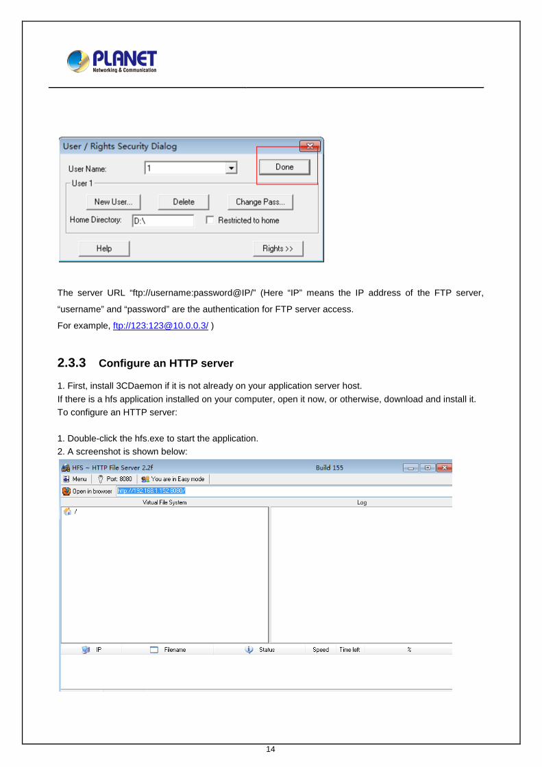
The server URL “ftp://username:password@IP/” (Here “IP” means the IP address of the FTP server,
“username” and “password” are the authentication for FTP server access.
For example, ftp://123:[email protected]/ )
2.3.3 Configure an HTTP server
1. First, install 3CDaemon if it is not already on your application server host. If there is a hfs application installed on your computer, open it now, or otherwise, download and install it. To configure an HTTP server: 1. Double-click the hfs.exe to start the application. 2. A screenshot is shown below:

15
3. Click menu, then select the IP address to choose the PC’s IP.
4. The default HTTP port is 8080. You can also reset the HTTP port (make sure the port isn’t used before you reset).
5. Right-click the icon on the left of the main page. Select Add folder from disk to add the HTTP Server root directory.
6. Locate the root directory from the computer system. Select the kind of folder which you deployed.

16
7. Check the server URL “http:// IP:Port/” in the “Open in browser” address bar (For example, the server
URL ”http:// 192.168.1.152:8080/” is shown on the screenshot). We recommend that you can fill out the
server URL in the address bar of the web browser and then press <Enter> key to check the HTTP server
before provisioning.
2.3.4 Configure a DHCP server Before configuring the DHCP Server, please make sure that: There is no DHCP server in your local system. Or it will cause some unknown consequences on deploy procedure. If you have a dhcpsrv2.3 application installed on your computer, open it now, or otherwise, download and install it. To configure a DHCP server: 1. Open the dhcpsrv2.3 folder
2. Open the application “dhcpwiz.exe” to configure the DHCP Server.
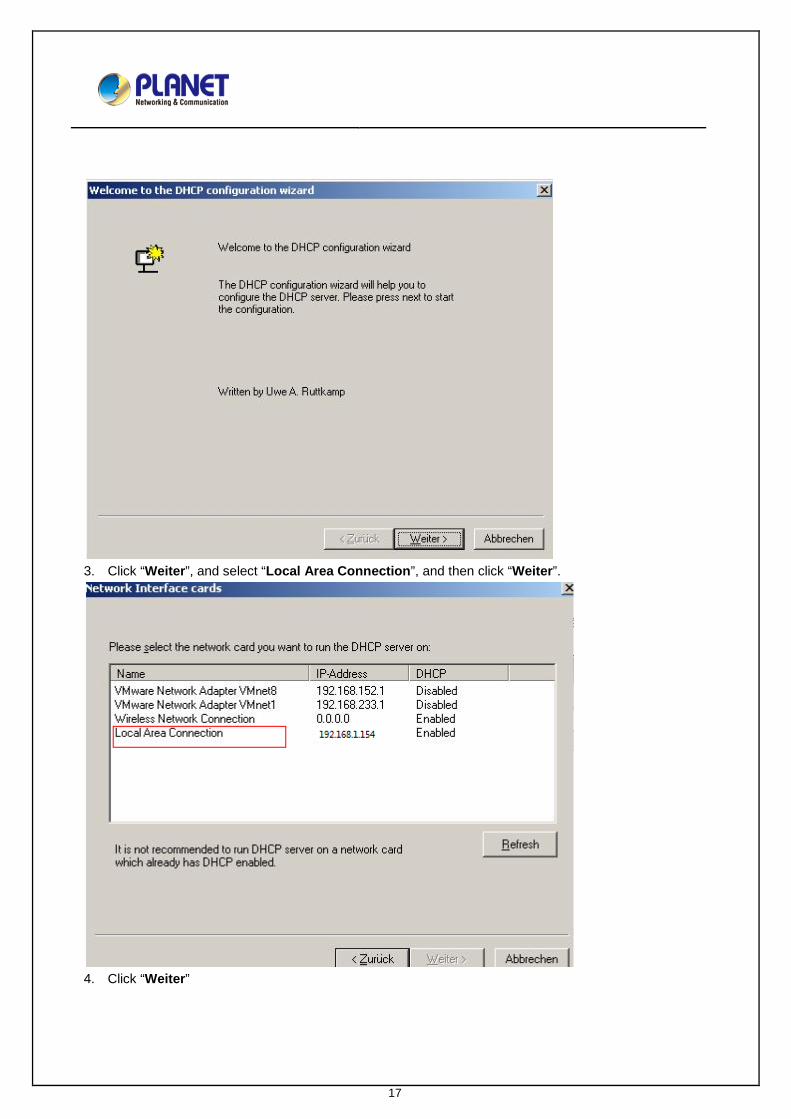
17
3. Click “Weiter”, and select “Local Area Connection”, and then click “Weiter”.
4. Click “Weiter”


19
7. You can add the needed DHCP option value, and fill out the provisioning server address in the input
field. Take option 66 for example.


21
9. Select “Overwrite existing file”, and then click “Write INI file”.
10. Click “Install”, and then click “start”.
11. Click “Fertig stellen” to accomplish the DHCP option configuration.

22
Note: Follow the above steps to finish setting the DHCP Server. If you use DHCP Server, just double-click
23
CHAPTER 3. QUALITY OF SERVICE (QOS) –
ENHANCE THE COMMUNICATION
QUALITY
3.1 VLAN
3.1.1 Introduction
VLAN (Virtual Local Area Network) is used to logically divide a physical network into several broadcast
domains. VLAN membership can be configured through software instead of physically relocating devices
or connections. Grouping devices with a common set of requirements regardless of their physical location
can greatly simplify network design. VLANs can address issues such as scalability, security and network
management.
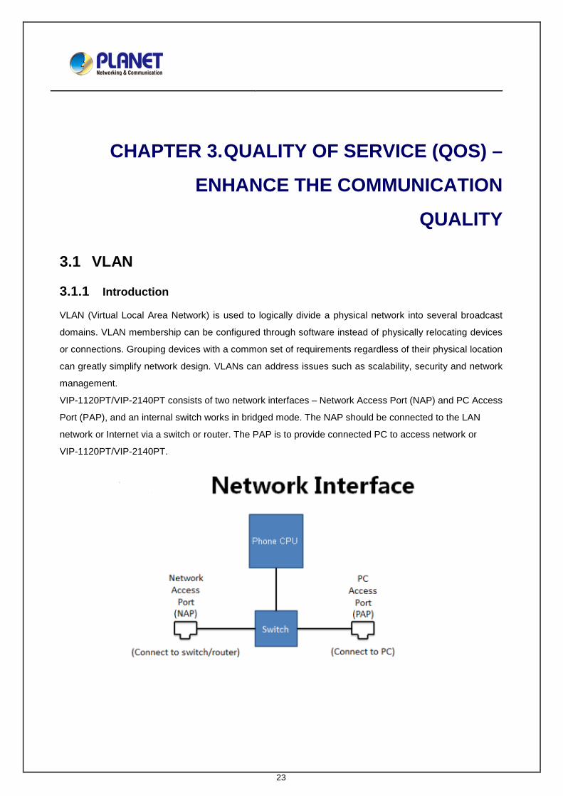
VIP-1120PT/VIP-2140PT consists of two network interfaces – Network Access Port (NAP) and PC Access
Port (PAP), and an internal switch works in bridged mode. The NAP should be connected to the LAN
network or Internet via a switch or router. The PAP is to provide connected PC to access network or
VIP-1120PT/VIP-2140PT.

24
When VIP-1120PT/VIP-2140PT is configured with an VLAN ID, the VLAN ID will be applied on the
outbound packets sent from VIP-1120PT/VIP-2140PT core CPU. This includes all packets, such as ARP,
ICMP, DHCP, DNS, HTTP(S), FTP, SIP, etc.
For packets of which destination is not to VIP-1120PT/VIP-2140PT core CPU, it will be copied to the other
port and will not be added any VLAN ID, nor to remove any. In another words, packets to and from
connected PC will be kept as they are.
While VIP-1120PT/VIP-2140PT tags its outgoing packets with configured VLAN ID, it can accept and
process packets with any VLAN ID or no VLAN ID for both NAP and PAP as long as the destination is to
VIP-1120PT/VIP-2140PT core CPU address.
3.1.2 Configure VLAN for VoIP Priority
QoS is for mobile phone data packets. It is able to distinguish between voice and data application. It is a common practice in a managed network to configure voice and data application using different
VLANs for prioritization. To separate voice and data traffic by VLAN, the administrator should configure a
VLAN switch with two separated VLANs – One for the voice which goes through a high priority trunk while
the other for data which goes through a normal priority trunk.
The VLAN switch configuration is different from each VLAN switch provider. The administrator should
follow its manual to configure the switch correctly.
For some advanced L2 switch with ALG function, it can identify voice related packets and tagged VLAN ID
automatically which needs no configuration on the phone. For basic L2 switch which supports VLAN
configuration, it must be configured to have certain ports that belong to the voice VLAN and certain ports
that belong to data port and the connected device should have corresponded to tagged VLAN ID,
otherwise, the packets will be discarded.
The folowing pictures show two simple configurations on a VLAN switch to support voice and data priority.

26
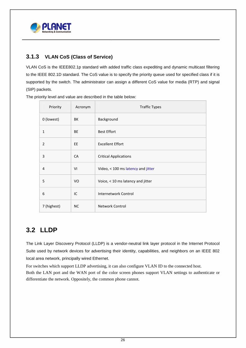
3.1.3 VLAN CoS (Class of Service)
VLAN CoS is the IEEE802.1p standard with added traffic class expediting and dynamic multicast filtering
to the IEEE 802.1D standard. The CoS value is to specify the priority queue used for specified class if it is
supported by the switch. The administrator can assign a different CoS value for media (RTP) and signal
(SIP) packets.
The priority level and value are described in the table below:
Priority Acronym Traffic Types
0 (lowest) BK Background
1 BE Best Effort
2 EE Excellent Effort
3 CA Critical Applications
4 VI Video, < 100 ms latency and jitter
5 VO Voice, < 10 ms latency and jitter
6 IC Internetwork Control
7 (highest) NC Network Control
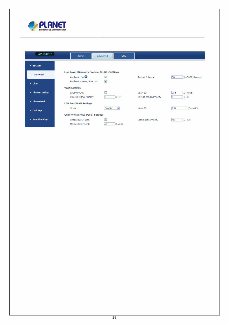
3.2 LLDP
The Link Layer Discovery Protocol (LLDP) is a vendor-neutral link layer protocol in the Internet Protocol
Suite used by network devices for advertising their identity, capabilities, and neighbors on an IEEE 802
local area network, principally wired Ethernet.
For switches which support LLDP advertising, it can also configure VLAN ID to the connected host. Both the LAN port and the WAN port of the color screen phones support VLAN settings to authenticate or differentiate the network. Oppositely, the common phone cannot.

27
To enable LLDP and VLAN learning, user can check the “Enable LLDP” and “Enable Learning Function” in
VIP-1120PT/VIP-2140PT web portal [Network/Advanced /LLDP Settings]
3.3 DSCP
Differentiated services or DiffServ is a computer networking architecture that specifies a simple, scalable
and coarse-grained mechanism for classifying and managing network traffic and providing quality of
service (QoS) on modern IP networks. DiffServ can, for example, be used to provide low-latency to critical
network traffic such as voice or streaming media while providing simple but best service to non-critical
services such as web traffic or file transfers.
DiffServ uses a 6-bit differentiated services code point (DSCP) in the 8-bit Differentiated services Field (DS
field) in the IP header for packet classification purposes. The DS field and ECN field replace the outdated
IPv4 TOS field.
To configure the QoS, user can get access to VIP-1120PT/VIP-2140PT web portal [Network/Advanced /
Quality of Service (QoS) Settings]

29
CHAPTER 4. ACTION URL AND ACTIVE URI –
COLLABORATIVE WORKING
ENVIRONMENT THROUGH
COMPUTER TELEPHONY
INTEGRATION (CTI)
4.1 Introduction
Action URL allows devices to interact with web server applications by sending an HTTP GET request. You
can specify a URL that triggers a GET request when a specified event occurs. Action URL can only be
triggered by the pre-defined events (e.g., Incoming Call). The valid URL format is:
http://<server address>/<processing file>?<variable name=$variable>.
The HTTP GET request may contain variable name and variable value, separated by “=”. Each variable
value starts with $ in the query part of the URL. Variable name can be customized by users, while the
variable value is pre-defined.
For example, an URL “http://192.168.1.100/newcall.xml?num=$call_id” is specified for the New call,
$call_id will be dynamically replaced with the real value of device when the device makes a call.
The following table lists the pre-defined events for action URL.
Event Description
Setup Completed When the device completes startup.
Registration Succeeded When the device successfully registers an
account.
Registration Disabled When the device logs off the registered account.
Registration Failed When the device fails to register an account.
Phone Off Hooked When the device is off hook.
Phone On Hooked When the device is on hook.

30
Event Description
Incoming Call When the device receives an incoming call.
Outgoing Call When the device places a call.
Call Established When the device establishes a call.
Call Terminated When the device terminates a call.
DND Enabled When the device enables the DND mode.
DND Disabled When the device disables the DND mode.
Unconditional Call Forward Enabled When the device enables the unconditional call
forward.
Unconditional Call Forward Disabled When the device disables the unconditional call
forward.
Call Forward on Busy Enabled When the device enables the Call Forward on
busy.
Call Forward on Busy Disabled When the device disables the Call Forward on
busy.
Call Forward on No Answer Enabled When the device enables the Call Forward on no
answer.
Call Forward on No Answer Disabled When the device disables the Call Forward on no
answer.
Call transfer When the device transfers a call.
Unattended Call Transfer When the device blind transfers a call.
Attended Call Transfer When the device performs the
semi-attended/attended transfer.
Call hold When the device places a call on hold.
Call resume When the device retrieves a hold call.
Mute When the device mutes a call.
UnMute When the device un-mutes a call.
Missed Call When the device misses a call.
IP Changed When the IP address of the device changes.
Idle To Busy When the state of the device changes from idle to
busy.
Busy To Idle When the state of phone changes from busy to
idle.

31
The following table lists pre-defined variable values. Variable Value Description
$Mac The MAC address of the device
$IP The IP address of the device
$model The device model
$firmware The firmware version of the device
$active URL
The SIP URI of the current account when the
device places a call, receives an incoming call or
establishes a call.
$active user
The user part of the SIP URI for the current
account when the device places a call, receives
an incoming call or establishes a call.
$active host
The host part of the SIP URI for the current
account when the device places a call, receives
an incoming call or establishes a call.
$local host
The SIP URI of the caller when the device places
a call. The SIP URI of the callee when the device
receives an incoming call.
$remote
The SIP URI of the callee when the device places
a call. The SIP URI of the caller when the device
receives an incoming call.
$display local
The display name of the caller when the device
places a call. The display name of the callee
when the device receives an incoming call.
$display remote
The display name of the callee when the device
places a call. The display name of the caller when
the device receives an incoming call.
$call ID. The call-id of the active call.
4.2 Action URL configuration
To configure action URL via web user interface:
1 Click on Phone Settings -> -> Features -> Action URL event Settings
2 Enter the action URLs in the corresponding fields.


33
CHAPTER 5. ACTIVE URI
5.1 Introduction
Unlike action URL, active URI allows devices to interact with web server application by receiving and
handling a HTTP GET request. When receiving a GET request, the IP phone will perform the specified
action and respond with a 200 OK message. A GET request may contain variable named as “key” and
variable value, which are separated by “=”. Besides, the command may contain more than one variable,
separated by “;”.
The valid URI format is:
http:// <username>:<password>@<server address>/cgi-bin/ConfigManApp.com?key=<variable value>.
For example:
(http://admin:[email protected]/cgi-bin/ConfigManApp.com?key=SPEAKER;8311;ENTER )
The following table lists pre-defined variable values:
Variable Value Description
OK Press the OK key .
ENTER Press the Enter soft key.
SPEAKER Press the Speakerphone key.
RELEASE Return to the standby status.
F_TRANSFER Transfers a call to another party.
VOLUME_UP Increase the volume.
VOLUME_DOWN Decrease the volume.
MUTE Mute the call.
F CFWD Call Forward settings menu
F_HOLD Place an active call on hold.
F _ CANCEL / X Cancel actions or reject incoming calls
0-9/*/POUND Press the keypad (0-9, * or #).
D1-D40 Press the memory keys.
F_CONFERENCE Press the CONF key or the Conference soft key
F1-F4 Press the soft keys
MSG Press the MESSAGE key.
F_PBOOK Press the Phonebook key.

34
HEADSET / F_HEADSET Press the HEADSET key.
RD Press the RD key.
UP/DOWN/LEFT/RIGHT Press the navigation keys.
Reboot Reboot the IP phone.
DNDOn Activate the DND feature.
DNDOff Deactivate the DND feature.
F_LOCK Keyboard Lock settings.
5.2 Active URI configuration
Generally, if someone who is able to get access to the Web server with authentication, the devices will
receive all the HTTP GET requests by default. But for security reasons, on some cases, users want to limit
restriction to active URI Source IP. You need to specify the trusted IP address for Active URI. You can
specify a trusted IP address on the IP phone, or configure the IP phone to receive and handle the URI from
any IP address.
To configure action URL via web user interface:
1 Click on Phone Settings -> Features -> Restrict Active URI Source IP
2 Enter the IP address or any in the Active URI that allows IP. If you leave the field blank, the IP phone
will receive or handle any HTTP GET request with authentication.
3 Click Apply to accept the change.

35
5.3 Daylight Saving Time Settings
The color screen product time zone configuration is different with common screen of the
VIP-1120PT/VIP-2140PT product. The color screen product have the Daylight Saving time Settings. You
can set it via Phone Settings—>Time/Date—>Daylight Saving Time Settings as the following dialog
shows:
36
CHAPTER 6. TRAVERSING NAT
6.1 Introduction
Network Address Translation (NAT) is a methodology of remapping internal IP address space to
external one by modifying source/destination network address and port field in IP packets when they are
transmitted through router or firewall. Not all of network devices could be assigned to a public IP address
when it accesses internet due to the shortage of amount of IPv4 address. The NAT helps a lot of these
network devices to share public IP address to visit Internet.
But it is very hard to send information to the device under NAT. And it is crucial to VoIP device
because server needs to know how to send incoming call request to the phone in local private network.
NAT traversal has been proposed to solve this problem. There are many technologies that could be used
to do NAT Transversal, such as STUN (RFC5389), ICE(RFC5245), TURN(RFC5766), symmetric
Response (RFC3581, Rport), etc. In this guide, we only discuss two NAT Traversal methods which X
series phone have implemented.
6.2 STUN
Session Traversal Utilities for NAT (STUN) is a network protocol to allow network device to discover
its public IP address through the assistant of 3-party sever on public network. It could also discover the
NAT type and binding port of NAT for local network device.
After applying the appropriate configurations for STUN, or loading the STUN configuration, our X
series phone would access STUN server first to detect the public IP address, NAT binding port and type of
NAT. There are four types of NATs generally, which STUN could not handle the traversal under symmetric
NAT. After the STUN server responds successfully, phone would send packets to STUN server through
SIP local port (default 5060), and wait the response to modify SIP URI. Then a request from local network
to public SIP server would contain URI information like packets to which a public IP address sent. Sever
feeds back response to the public IP address and port would come back to local device through NAT. So,
server could find local device under NAT easily. When phone call is made, it would use STUN to discover
binding RTP port on NAT again, and fill out the information on SDP session. And then a voice media
connection would be built between local device and public device.
Note:
1. STUN could not handle the case under symmetric NAT.

37
2. In some special situations, phones under same local network could not set up connection
successfully when STUN is enabled. Because some NATs would refuse to transmit data packets on two
binding ports over NAT. So default setting of STUN is disabled. STUN could be enabled by web user
interface or importing configuration file.
Configuration method:
1. Web user interface
1) Click ‘Line/Basic Settings ’.
2) Modify the field ‘STUN Settings/ Server Address’ with domain name of STUN sever or IP address.
3) Click the “Apply” button to save the change.
4) Click ‘Line/SIP/Advanced Settings’ when Line 1 needs to use STUN to do NAT Traversal.
5) Make sure that ‘use STUN’ checkbox is checked.
6) Click the ‘Apply’ button to save the change.
Here is an example:
2. Items in configuration file
There are also two parts in configuration file for STUN, common configuration and line configuration.
1) Common configuration
Parameters Descriptions
STUN Server : Configure Domain or IP address of STUN server.
Default value is empty.
STUN Port : Configure STUN server port, default is 3478。
STUN Refresh Time : Configure STUN request sending period by

38
seconds. Default value is 50 seconds.
SIP Wait Stun Time : Configure the timeout which phone would wait
STUN response before SIP request is sent. Default
value is 800 ms.
Here is an example to set STUN server to ‘stun1.voiceeclipse.net’.
a) Export configuration files from Web user interface.
b) Find ‘<SIP CONFIG MODULE>’
c) Modify the fields shown below:
STUN Server :stun1.voiceeclipse.net
STUN Port :3478
STUN Refresh Time :50
SIP Wait Stun Time :800
2) Line configuration:
Parameters Descriptions
SIP1 NAT Type : Configure Line 1 that uses STUN as its NAT
traversal method. 0 is Disabled, 1 is Enabled.
Default is 0.
SIP2 NAT Type : Configure Line 2 that uses STUN as its NAT
traversal method.
Note: These two configuration items should be listed below ‘ --SIP Line List-- :’
Here is example to set line 1 STUN enable and line 2 disable.
--SIP Line List-- :
SIP1 NAT Type :1
SIP2 NAT Type :0
6.3 Rport
Rport is another NAT Traversal method in SIP stacks. It is also a keyword string in SIP information.
RFC3581 describes the implementation of Rport, which is also called Symmetric Response. After SIP
server received a UDP request, it should check whether there is ‘rport’ string in the ‘Via’ field and its value
is empty. If so, the server should insert ‘received’ parameter and ‘rport’ parameter in the ‘via’ field when it
sends response to the client. The value of ‘received’ parameter should be the IP address from which its
packets are directly. And the address might be NAT device’s address or phone’s address connecting to

39
public network. In addition, the value of ‘rport’ parameter is equalled to port from public IP address. SIP
server will keep client device’s NAT mapping IP and port information and send request via the field. This
method would not need 3-party server to find NAT mapping information, and have been supported in many
types of SIP server. So the default configuration value of Rport in X series phone is 1 (enabled).
Configuration method:
1. configuration by web user interface
1) Click ‘Line/SIP/Advanced Settings’ when you want to configure Rport setting for Line1
2) Make sure checkbox of ‘Enable Rport’ is checked when you want Rport to be active.
3) Click the ‘Apply’ button to save the changes.
2. Items in configuration file
Parameters Descriptions
SIP1 Enable Rport Configure Line 1 enables Rport feature or not. 0 is
Disabled, 1 is Enabled. Default is 1.