adose-d8.4 pu v01 ok report - europa - trimis |...
TRANSCRIPT

RELIABLE APPLICATION SPECIFIC DETECTION
OF ROAD USERS
WITH VEHICLE ON-BOARD SENSORS
Public Page 1 of 25
DOCUMENT
DELIVERABLE NUMBER D8.4 DUE DATE 30/11/2011
ISSUED BY CRF ACTUAL DATE 31/01/2012
CONTRIBUTING WP/TASK WP0 / TASK 8.3 PAGES 25
CONFIDENTIALITY STATUS PUBLIC ANNEXES -
PROJECT
GRANT AGREEMENT NO. 216049
ACRONYM ADOSE
TITLE RELIABLE APPLICATION SPECIFIC DETECTION OF ROAD
USERS WITH VEHICLE ON-BOARD SENSORS
CALL FP7-ICT-2007-1
FUNDING SCHEME STREP
DELIVERABLE D8.4
TECHNOLOGY IMPLEMENTATION PLAN
AUTHOR
CRF N. PALLARO
APPROVAL
PROJECT COORDINATOR CRF N. PALLARO
AUTHORISATION
PROJECT OFFICER EUROPEAN COMMISSION I. HEIBER

Public Page 2 of 25
DELIVERABLE D8.4
TECHNOLOGY IMPLEMENTATION PLAN
Ver. 01 Date 31/01/2012 Page 2 of 25
REVISION HISTORY
VER. DATE PAG. NOTES AUTHOR
00 17/11/2011 All Template N. Pallaro (CRF)
01 31/01/2012 All Final version N. Pallaro (CRF)

Public Page 3 of 25
DELIVERABLE D8.4
TECHNOLOGY IMPLEMENTATION PLAN
Ver. 01 Date 31/01/2012 Page 3 of 25
TABLE OF CONTENTS
1. INTRODUCTION ................................................................................................................................................ 4
1.1 SCOPE OF THE ADOSE PROJECT ................................................................................................................... 4
1.2 OVERALL RESULTS OF THE TECHNOLOGICAL IMPLEMENTATION ..................................................................... 7
2. SUMMARY OF THE ADOSE PROJECT KEY RESULTS ........................................................................ 10
2.1 RESULT #1 – HYBRID BACKSIDE ILLUMINATED IMAGER MANUFACTURING TECHNOLOGY ............................ 13
2.2 RESULT #2 – FIR CAMERA ............................................................................................................................ 13
2.3 RESULT #3 – WAFER MOULDING TECHNOLOGY IR OPTICS .......................................................................... 14
2.4 RESULT #4 – CMOS IMAGER ........................................................................................................................ 15
2.5 RESULT #5 – PASSIVE / ACTIVE TAGS .......................................................................................................... 16
2.6 RESULT #6 – WIRELESS SENSORS ............................................................................................................... 17
2.7 RESULT #7 – RADAR ECU SOFTWARE MODULE ........................................................................................... 17
2.8 RESULT #8 – MULTIFUNCTIONAL CAMERA (MFOS) - DIOPTRIC LIGHTGUIDE .............................................. 18
2.9 RESULT #9 – MULTIFUNCTIONAL CAMERA (MFOS) - PLANAR LIGHTGUIDE ................................................. 19
2.10 RESULT #10 – HARMONIC RADAR ........................................................................................................... 20
2.11 RESULT #11 – SILICON RETINA STEREO (SRS) OPTICAL HIGH SPEED SENSOR .................................. 20
3. INDUSTRIAL PERSPECTIVES .................................................................................................................... 22
3.1 AUTOMOTIVE MARKET .................................................................................................................................... 22
3.2 NON-AUTOMOTIVE MARKETS ......................................................................................................................... 22
3.2.1. Building inspection ................................................................................................................................ 22
3.2.2. Process control ...................................................................................................................................... 22
3.2.3. Low cost security and surveillance ..................................................................................................... 22
4. EXPLOITATION STRATEGIES .................................................................................................................... 23
4.1 PREPARING FOR A CROSS-SECTOR DEPLOYMENT ACTIVITIES ...................................................................... 23
4.2 DISSEMINATION OF ADOSE RESULTS DURING THE PROJECT ...................................................................... 23
4.3 PROMOTION OF ADOSE RESULTS AFTER PROJECT END ............................................................................. 24
5. CONCLUSION ................................................................................................................................................. 25
6. ANNEX - LIST OF FIGURES AND TABLES ............................................................................................. 25

Public Page 4 of 25
DELIVERABLE D8.4
TECHNOLOGY IMPLEMENTATION PLAN
Ver. 01 Date 31/01/2012 Page 4 of 25
1. INTRODUCTION
The ADOSE project is funded within the 7th Framework R&D Programme running from 01 Jan. 2008 to 30 Nov. 2011. ADOSE aimed at enhancing ADAS functions through the development of high performance and low lost sensing technologies suitable for reliable detection and classification of road users in hostile environments.
1.1 Scope of the ADOSE project
Project reason
The European Commission has been actively supporting a number of safety related projects, as part of its initiative to pursue the goal of considerably reducing road accidents. Past and running projects focused on preventive and active safety have clearly identified some basic functional, performance and cost limits of current sensors and ADAS systems. These limits can be seen as breakthrough opportunities at hardware and software levels, helping in the fulfillment of applications objectives and in the effective deployment of advanced driver assistance systems. Some hardware aspects concern sensing technologies (for which a recent boost has been observed regarding vision devices), communication interfaces (data buses) and housing. Software aspects concern sensor data pre-processing and application interfaces (access to raw and pre-processed data for instance).
Three main functional requirements, relevant to ADAS systems, have been addressed in ADOSE:
• Reliable obstacle detection and classification, with reduced environmental influences and false positive rate at high recognition rates:
o Detection of pedestrians in urban and extra urban scenarios for warning night-vision applications, collision mitigation and avoidance of pedestrians at night.
o Detection of all road users including pedestrians in urban scenarios in the near field for pre-crash applications, collision mitigation and avoidance systems as well as emergency braking.
• Fast, precise and reliable measurements of both range and angle of closing objects with high resolution and wide field of view under all weather conditions (in Vulnerable Road Users & Collision Mitigation function).
• Visibility measurements (fog, mist) which are very important for the assistance task to the preventive safety functions.
Performance, robustness and reliability of ADAS can be improved through sensor enhancements at hardware and/or software levels, sensor data fusion and communication systems, and by introducing new sensor technologies. Among the technological needs addressed to sensor enhancement there are:
• Sensors with wider field of view and higher spatial resolution (e.g. overcoming of present ranging camera with large area custom pixel and low resolution, CMOS imager with more than 1 Mpixels)
• Sensors with higher sensitivity and high dynamic range (e.g. CMOS imager with enhanced response in the near infrared band-NIR, ranging camera with higher fill factor)
• Sensors with higher temporal resolution and low-processing power (e.g. sensor for pre-crash application)

Public Page 5 of 25
DELIVERABLE D8.4
TECHNOLOGY IMPLEMENTATION PLAN
Ver. 01 Date 31/01/2012 Page 5 of 25
• Multifunctional sensors as "application independent" sensors • New (friction, visibility, etc.) and improved (radar, vision, etc.) sensors
Objectives
ADOSE addressed research challenges in the area of accident prevention; the focus was on functional, performance and cost limits of current sensors and Advanced Driver Assistance Systems for their extensive market penetration. ADOSE has been set up in the context of the “European Technology Platform on Smart Systems Integration” (EPoSS) and it aimed at being a product driven project by the development and integration of Smart Systems and Technologies for Preventive and Active Safety. The goal was the enhancement of safety functions through the development of high performance and low cost sensing technologies suitable for reliable detection and classification of obstacles and vulnerable road users in hostile environments. The project focused mainly on sensing elements and their pre-processing hardware, as a complementary project to PReVENT.
Figure 1 - Challenges regarding ADAS sensors addressed in ADOSE
Five sensor module prototypes have been designed, fabricated and tested:
o FIR camera (FIR) o Multifunctional CMOS vision sensor (MFOS) o 3D range camera (3DCAM) o Harmonic radar with passive and active tags (HR P-TAG, HR A-TAG) o Silicon retina stereo sensor (SRS)
Only 'technology-dependent' pre-processing algorithms have been developed for each sensor: (a) algorithms implemented into the sensor hardware; (b) algorithms on raw data, coming from the sensor hardware, implemented on a PC-based processing hardware, strictly related to the sensing technology and its demonstration. Algorithm developments have not been extended to Sensor Data Fusion. Demonstration have been limited to functional sensor prototypes installed on concept cars without integrating the complete safety system.
Public Page 6 of 25
DELIVERABLE D8.4
TECHNOLOGY IMPLEMENTATION PLAN
Ver. 01 Date 31/01/2012 Page 6 of 25
Technologies
ADOSE addressed five breakthrough sensing technologies, with the goal to improve the current state-of-the-art in terms of performance, reliability and costs:
o FIR-add-on sensor (FIR), with good thermal and spatial resolution at lower cost, to be combined to a high resolution imager for enhanced night vision applications (more reliable obstacle detection and classification).
o Low-cost multi-functional and multi-spectral CMOS vision sensor (MFOS), detecting critical environmental parameters (fog, rain, …) and providing, at the same time, information on the driving scenario (oncoming vehicles, VRUs in night conditions, …).
o High spatial resolution and low-cost 3D range camera (3DCAM), based on 3D packaging, optical CMOS and laser radar technologies for short range safety requirements (high-speed object recognition and distance measurement, e.g. for Pre-crash).
o Harmonic radar combined to passive nonlinear reflector and active tags (HR-PTAG and HR-ATAG), enabling easy detection of traffic obstacles and vulnerable road users, and their identification, even in dark or adverse weather conditions.
o High temporal resolution and low-cost bio-inspired silicon retina stereo sensor (SRS), addressing time critical decision applications.
Applications
ADOSE impacts on the “virtual safety belt” around the vehicle by offering different sensing technologies with potential for a set of complementary safety functions. ADOSE sensors can have a strong impact on both independent and integrated (based on sensor fusion) safety systems.

Public Page 7 of 25
DELIVERABLE D8.4
TECHNOLOGY IMPLEMENTATION PLAN
Ver. 01 Date 31/01/2012 Page 7 of 25
Figure 2 - Potential ADAS applications addressed by ADOSE sensors
1.2 Overall results of the technological implementation
In the present Technological Implementation Plan, a total of 11 exploitable results are described (see table B2, chapter 3), as major outcome concerning the ADOSE development and implementation of:
• Core technologies;
• Hardware components;
• Software code;
• Functional systems.

Public Page 8 of 25
DELIVERABLE D8.4
TECHNOLOGY IMPLEMENTATION PLAN
Ver. 01 Date 31/01/2012 Page 8 of 25
Figure 3 summarises the overall results of the technological implementation, showing the ADOSE architecture where all the exploitable results are identified. The reference of the companies that are the main contact point for the individual results are also included.
The ADOSE achievements have been developed at prototype level and validated on vehicle in real scenarios, with the exception of the harmonic radar and 3D camera that were only tested in lab.

Public Page 9 of 25
DELIVERABLE D8.4
TECHNOLOGY IMPLEMENTATION PLAN
Ver. 01 Date 31/01/2012 Page 9 of 25
Figure 3 - Overall results of the technological implementation, in relationship with the ADOSE architecture
TEMPORAL
COMMON
REFERENCE
SPATIAL
COMMON
REFERENCE
SENSOR
MODELS
SENSOR
REFINEMENT
FEATURE
EXTRACTION
OBJECT
CLASSIFICATION
SEQUENTIAL
ESTIMATION
OBJECT
REFINEMENT
OB
JE
CT
S
OB
SE
RV
AT
ION
S
ADDRESSED WITHIN ADOSE
PRE-PROCESSINGCHIP / OPTICS
R2 – BOSCH
FIR camera
R3 – UMICOREWafer moulding
technology IR optics
R4 – STMCMOS imager
R5 – VTT
Passive / Active tags
R8 – CRFMultifunctional camera
(MFOS) - dioptric lightguide
R6 – VTT
Wireless sensors
R11 – AIT
Silicon Retina Stereo (SRS) Optical High
Speed Sensor
R10 – TRIADHarmonic Radar
R1 – imecHybrid backside
illuminated imager manufacturing technology
R7 – VTTRadar ECU
software module
R9 – IZMMultifunctional camera
(MFOS) - planar lightguide
SENSOR HARDWARE
PRE-PROCESSINGCHIP / OPTICS
PRE-PROCESSINGCHIP / OPTICS
PRE-PROCESSINGCHIP / OPTICS
PRE-PROCESSINGCHIP / OPTICS
SW PERCEPTION LAYER
FIR
MFOS
3DCAM
HR-PTAG /ATAG
SRS

Public Page 10 of 25
DELIVERABLE D8.4
TECHNOLOGY IMPLEMENTATION PLAN
Ver. 01 Date 31/01/2012 Page 10 of 25
2. SUMMARY OF THE ADOSE PROJECT KEY RESULTS
TEMPLATE B2: LIST OF EXPLOITABLE FOREGROUND
No. Type of Exploitable Foreground
1
Description of exploitable
foreground
Confidential Click on YES/NO
Foreseen embargo
date dd/mm/yyyy
Exploitable product(s) or measure(s)
Sector(s) of application
2
Timetable, commercial or any other use
Patents or other IPR exploitation (licences)
Owner & Other Beneficiary(s) involved
CORE TECHNOLOGIES
1
General advancement of knowledge
Hybrid backside illuminated imager manufacturing technology
YES - Advanced imagers with high light sensitivity
1. Scientific 2. Manufacturing 3. Automotive
1. 2013-2014 2. 2015 3. >2015
- imec
HARDWARE COMPONENTS
2
Commercial exploitation of R&D results
FIR camera YES - FIR camera 1. - 2. ADAS
1. Non-automotive (building, industrial, security) 2. Automotive
1. 2 years 2. 3-5 years
no Bosch (owner)
3
Commercial exploitation of R&D results
Wafer moulding technology IR optics
YES - FIR camera 1. ADAS
1. Automotive 2.Security and surveillance 3. Commercial
1. 2018 2. 2015 3. 2014
no
Umicore (owner)
4
Commercial exploitation of R&D results
CMOS imager YES - Camera module: 1. ADAS
1. Automotive 2. Security
1. 2012 (1st gen.) 1. 2015 (2nd gen.) 2. 2013
no ST Microelectronics (owner)
5 Commercial Passive / Active YES - ADAS Automotive First prototypes US and PCT VTT(owner), partners
6 A drop down list allows choosing the type of foreground: General advancement of knowledge, Commercial exploitation of R&D results, Exploitation of R&D results via standards,
exploitation of results through EU policies, exploitation of results through (social) innovation.
2 A drop down list allows choosing the type sector (NACE nomenclature) : http://ec.europa.eu/competition/mergers/cases/index/nace_all.html

Public Page 11 of 25
DELIVERABLE D8.4
TECHNOLOGY IMPLEMENTATION PLAN
Ver. 01 Date 31/01/2012 Page 11 of 25
TEMPLATE B2: LIST OF EXPLOITABLE FOREGROUND
No. Type of Exploitable Foreground
1
Description of exploitable
foreground
Confidential Click on YES/NO
Foreseen embargo
date dd/mm/yyyy
Exploitable product(s) or measure(s)
Sector(s) of application
2
Timetable, commercial or any other use
Patents or other IPR exploitation (licences)
Owner & Other Beneficiary(s) involved
exploitation of R&D results
tags within 3 years patent pending outside the project
6 Commercial exploitation of R&D results
Wireless sensors YES - - Non-automotive First engineered prototypes within 3-5 years
US and PCT patent pending
VTT(owner), partners outside the project consortium (license)
SOFTWARE CODE
7
Commercial exploitation of R&D results
Radar ECU software module
YES - Integration with Harmonic Radar and/or Conventional Radar HW
1. Automotive 2. Aeronautics 3. Other Transport 4. Security
1. 2014 2. 2015 3. 2015 4. 2014
N/A PARAGON
FUNCTIONAL SYSTEM (sensor module, safety system, …)
8
Commercial exploitation of R&D results
Multifunctional camera (MFOS) - dioptric lightguide
YES - ADAS Automotive
1-2 years for industrialisation (depending on OEM request)
Pre-existing patents (no. 5, owner CRF) before ADOSE start
CRF (owner), MM (license for pre-existing patents), ST Microelectronics
9
Commercial exploitation of R&D results
Multifunctional camera (MFOS) - planar lightguide
YES - ADAS Automotive
3-5 years
-
IZM (owner), CRF (owner of pre-existing patents on multifunctional integration), ST Microelectronics
10
Commercial exploitation of R&D results
Harmonic Radar YES - ADAS 1. Automotive 2. Safety 3. Maritime 4. Security
18 months low volume, 36-48 moths high volume
Patent applications will be filed
TRIAD (partly also VTT)
11 Commercial exploitation of R&D results
Silicon Retina Stereo (SRS) Optical High
YES - ADAS 1. Automotive 2. Special vehicle
24 months - AIT (owner), partners outside the project consortium (license)

Public Page 12 of 25
DELIVERABLE D8.4
TECHNOLOGY IMPLEMENTATION PLAN
Ver. 01 Date 31/01/2012 Page 12 of 25
TEMPLATE B2: LIST OF EXPLOITABLE FOREGROUND
No. Type of Exploitable Foreground
1
Description of exploitable
foreground
Confidential Click on YES/NO
Foreseen embargo
date dd/mm/yyyy
Exploitable product(s) or measure(s)
Sector(s) of application
2
Timetable, commercial or any other use
Patents or other IPR exploitation (licences)
Owner & Other Beneficiary(s) involved
Speed Sensor
The exploitation of each result is inserted in a framework of cooperation that involves a number of stakeholders. Therefore the effective start-up of the exploitation phase do not depend only the partners that are indicated as result responsible, at least in most of the cases.

Public Page 13 of 25
DELIVERABLE D0.4-D0.5
TECHNOLOGY IMPLEMENTATION PLAN
Ver. 01 Date 31/05/2012 Page 13 of 25
2.1 Result #1 – Hybrid backside illuminated imager manufacturing technology
As part of the current project, imec has developed technology for the realization of hybrid backside illuminated imagers. In backside illuminated imagers, the imager is made out of 2 separate substrates, one which fulfils the detection function and one which fulfils the readout and basic signal processing function. This split of functionality allows for a smaller imager form factor: the available area for both light detection and readout circuitry doubles. Moreover, as the imager is backside illuminated, light coupling of incident light into the imager substrate can be optimized, thereby maximizing light sensitivity.
2.2 Result #2 – FIR camera
In ADOSE work package 2 Bosch developed technologies for low-cost production of components for an add-on FIR module for automotive night-vision systems. Bosch also developed a technique for chip-on-board assembly of the FIR imager to reduce assembly cost while simultaneously optimize the thermal management of the chip and the integrated ROIC. To evaluate and demonstrate the results and concept of the developed technologies Bosch set up a demonstrator camera that could be mounted to a car. The first image shows the demonstrator box with mounted optics and the electronics boards with mounted chip, the second image shows a chip-on-board assembly of an imager chip.
Figure 4 - FIR camera demonstrator
Figure 5 - Chip-on-board assembly of an imager chip
The most costly components of such a FIR camera are the imager chip and the FIR optics. For the FIR imager chip, BOSCH utilized an existing MEMS process for integrated pressure sensors and to establish a process for integrated thermo-diode arrays. Thus the required investments for the new sensor product is low and the economy of scale reduces the cost even further. The trade-off lies in the limited possibilities for process adjustments resulting in reduced performance compared to state-of-the-art un-cooled microbolometers. In ADOSE the first step was a small array with 42 by 28 quite large pixels used for proof of concept and the second step was a medium sized array with 100 by 50 pixels and 100µm pixel pitch, that was designed to fulfil the specification that was derived from the requirements and scenarios of work package 1.
The following images were taken with the ADOSE FIR camera demonstrator. From left to right: person outdoor in native resolution (100x50), a group of people outdoor with bicubic interpolation and the sideview of a human head, also with bicubic interpolation.
Public Page 14 of 25
DELIVERABLE D0.4-D0.5
TECHNOLOGY IMPLEMENTATION PLAN
Ver. 01 Date 31/05/2012 Page 14 of 25
Figure 6 - Image with native resolution
Figure 7 - Image with bicubic interpolation
Figure 8 - Image with bicubic interpolation
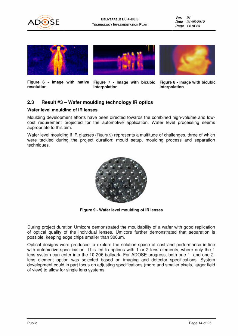
2.3 Result #3 – Wafer moulding technology IR optics
Wafer level moulding of IR lenses
Moulding development efforts have been directed towards the combined high-volume and low-cost requirement projected for the automotive application. Wafer level processing seems appropriate to this aim.
Wafer level moulding if IR glasses (Figure 9) represents a multitude of challenges, three of which were tackled during the project duration: mould setup, moulding process and separation techniques.
Figure 9 - Wafer level moulding of IR lenses
During project duration Umicore demonstrated the mouldability of a wafer with good replication of optical quality of the individual lenses. Umicore further demonstrated that separation is possible, keeping edge chips smaller than 300µm.
Optical designs were produced to explore the solution space of cost and performance in line with automotive specification. This led to options with 1 or 2 lens elements, where only the 1 lens system can enter into the 10-20€ ballpark. For ADOSE progress, both one 1- and one 2-lens element option was selected based on imaging and detector specifications. System development could in part focus on adjusting specifications (more and smaller pixels, larger field of view) to allow for single lens systems.

Public Page 15 of 25
DELIVERABLE D0.4-D0.5
TECHNOLOGY IMPLEMENTATION PLAN
Ver. 01 Date 31/05/2012 Page 15 of 25
Table 1 - ADOSE specifications
2.4 Result #4 – CMOS imager
Here follows the description of the modifications to the ST CMOS camera sensor, the VL5510, done by ST to render the sensor suitable for the ADOSE project. The main modifications had the purpose of guarantee the features necessary for the multifunctional integration for advanced safety applications and the automotive qualification. The original sensor was monochrome. ST modified to be a full color RGB sensor with a Bayer filter mosaic. The main advantages are the possibility to improve the recognition performances by feeding the image processing algorithms of more useful information, such as the color of the traffic signs, or the color of the taillights, etc.
Figure 10 - Integration of microlenses and Bayer filter in the CMOS imager

Public Page 16 of 25
DELIVERABLE D0.4-D0.5
TECHNOLOGY IMPLEMENTATION PLAN
Ver. 01 Date 31/05/2012 Page 16 of 25
Despite the fact that, from simulations and experimental tests, the VL5510 has a very good sensitivity, the capability to improve the performance is still a very challenging particularly for the fog and rain functions. This objective can be addressed by using micro-lenses to improve performance. The goal is not to perform an imaging onto each pixel but to improve the pixel sensitive area. It was noted that if the standard OLGA package would be used for optical coupling of the wave guides to the imager chip the optical glass foil has to be attached on top of the lid. The distance between the glass foil and the imager chip would be around 1.2 mm. Optical beam analysis has shown, that for reducing the spot size either a collimating lens must be integrated in between or the glass sheet must be positioned closer to the imager chip. Therefore the standard OLGA package has been modified to achieve a flat version in the modified package the distance between glass and pixel area will be reduced.
Figure 11 - Modified OLGA package
2.5 Result #5 – Passive / Active tags
Passive and active tags are used with an automotive radar to detect and classify vulnerable road users, traffic signs and other obstacles that require particular attention of a driver. An advantage of a passive tag is that it does not require a battery, which can limit its life time. On contrary, active tags powered by a battery offers larger detection distance. The third tag type is a semi-passive tag, that does not amplify the reflected signal, but uses a battery for powering up the IC. It provides larger detection distance compared to a passive tag and longer life-time than the active tag. A photograph of an active tag integrated into an optical reflector is shown in Figure 12.
Figure 12 - Active tag integrated into an optical reflector
The tags are fabricated on a flexible substrate such, that they could be integrated into clothing of pedestrians. The tags communicate with the radar using the modulated backscattering principle somewhat similar to the widely used RFID tags.

Public Page 17 of 25
DELIVERABLE D0.4-D0.5
TECHNOLOGY IMPLEMENTATION PLAN
Ver. 01 Date 31/05/2012 Page 17 of 25
2.6 Result #6 – Wireless sensors
In this project, passive radar transponders were developed for detecting and classifying vulnerable road users and other objects using a modified automotive radar. In addition to object detection, these transponders can be utilized as passive wireless sensors also in non-automotive applications. The sensors utilize the secondary radar operation principle, in which the signal emitted by the sensor is a harmonic frequency of a signal transmitted by the radar, or reader device.
In ADOSE project, VTT developed a sensor platform, which can be equipped with a generic capacitive sensor element, such as a MEMS pressure or inertial sensor. The possibility to use the concept to read out wirelessly a generic sensor element is the greatest benefit of the concept as compared to other passive wireless sensor technologies, such as RFID and surface acoustic wave (SAW) RFID. Other advantages of the concept are a long read-out distance (tens of meters at a few GHz frequency), relatively simple and inexpensive sensor architecture, and a possibility to use a high carrier frequency. High carrier frequency enables small sensor size and precise spatial localization of the sensor.
VTT has developed different sensor topologies that utilize a MEMS element, a ferroelectric varactor, and a varactor diode for mixing. A photograph of the varactor-based sensor prototype is shown in Figure 13.
Figure 13 - Varactor-based sensor prototype
2.7 Result #7 – Radar ECU software module
Radar ECU Software Module for Enhanced Object Detection & Tracking
The Radar ECU Software Module developed by PARAGON for Harmonic Radar + Tags (HR-TAG) combination includes in integrated form all algorithms necessary for a range of operations and pre-ADAS functions, i.e., Pre-processing of raw radar data, Detection (objects, vulnerable road users), Early sensor fusion, Object tracking & Trajectory prediction, Feature extraction.
The Radar ECU SW module (as an early sensor fusion stage) has been developed to be Modular (support of multiple radar sensors), Portable, and Customizable (application to either harmonic and/or conventional radar). In addition, all information concerning detected objects & their associated features are transferable to other ECUs (of either same type or other car sensors), or to any higher ADAS layer for further fusion and object & situation refinement processes.

Public Page 18 of 25
DELIVERABLE D0.4-D0.5
TECHNOLOGY IMPLEMENTATION PLAN
Ver. 01 Date 31/05/2012 Page 18 of 25
Figure 14 - Radar ECU software
Furthermore, the Radar SW module has been developed to also include extraction of data regarding car dynamics data from a vehicle’s CAN-bus. Such data in correlation with the information extracted from the aforementioned functions may enhance the features extraction (description, properties, etc) and tracking mode of detected objects and vulnerable road users by the vehicle user. Enhanced feature extraction features and functions, implementable via the Real-time Intelligent System, may contribute to the elevation of driver perception and reaction time/action with respect to detected - tracked object(s), per additional identifying characteristics such as for instance including further signal properties or behaviour patterns (e.g., shape, orientation, profile signature, size, manoeuvre intention, etc). 2.8 Result #8 – Multifunctional camera (MFOS) - dioptric lightguide
A multifunctional and multispectral camera (MFOS) aiming at integrating on a single CMOS array imaging and sensing functions has been developed. The final prototype is based on low cost plastic optical lightguides coupled to a standard CMOS imager enabling different functional integration:
•••• warning night vision, tunnel (imaging function);
•••• fog, twilight, rain (sensing functions). The sensing functions are monitored on two dedicated region of interests positioned in two corners (brighter or darker ROIs) of the imager area as shown Figure 15 during outdoor tests for twilight, tunnel/bridge and warning night vision functions.

Public Page 19 of 25
DELIVERABLE D0.4-D0.5
TECHNOLOGY IMPLEMENTATION PLAN
Ver. 01 Date 31/05/2012 Page 19 of 25
Figure 15 - Outdoor test of MFOS sensor (fog, tunnel and warning night vision).
The sensor prototype has been designed with the twofold goal of guaranteeing the required precision to couple the optics components and to pursue an easy to assembly procedure. The housing of the sensor prototype has been designed to be installed in the vehicle internal rear view mirror.
Figure 16 - MFOS camera prototype integrated in the internal rearview mirror
2.9 Result #9 – Multifunctional camera (MFOS) - planar lightguide
The second multifunctional approach investigated and developed in the project for the MFOS sensor is based on a new lightpipe concept. The structure was formed using two polymer substrates: a hot embossed lightpipe plate with cover plate made of the same polymer. Appropriate mirror structures and metal coating made by sputtering allow light to be coupled to all 4 ROIs on the imager chip. Hot embossing is a well suited rapid prototype technology and the results are easy to transfer to injection moulding for high volume processes. The lightpipe approach in plastic materials was identified as the most cost effective solution for mass production. Aluminim was chosen for the reflective coating because of cost effectiveness and its wide spectra reflectivity. The easy to assemble housing has been realised by rapid prototyping. The lenses have been designed according to the optical requirements of the light pipe plate and were manufactured using hot embossing at Fraunhofer IZM. These lenses are necessary to collect the light and to steer it inside the MFOS housing to the light pipe plate. The position of the optical inputs within the MFOS can be seen in the figure below.
Public Page 20 of 25
DELIVERABLE D0.4-D0.5
TECHNOLOGY IMPLEMENTATION PLAN
Ver. 01 Date 31/05/2012 Page 20 of 25
Figure 17 - MFOS assembled prototype: 1) optical fog function; 2) optical twilight; 3) IR-lighting with reflector; 4/5) input solar function; 6) optic imager
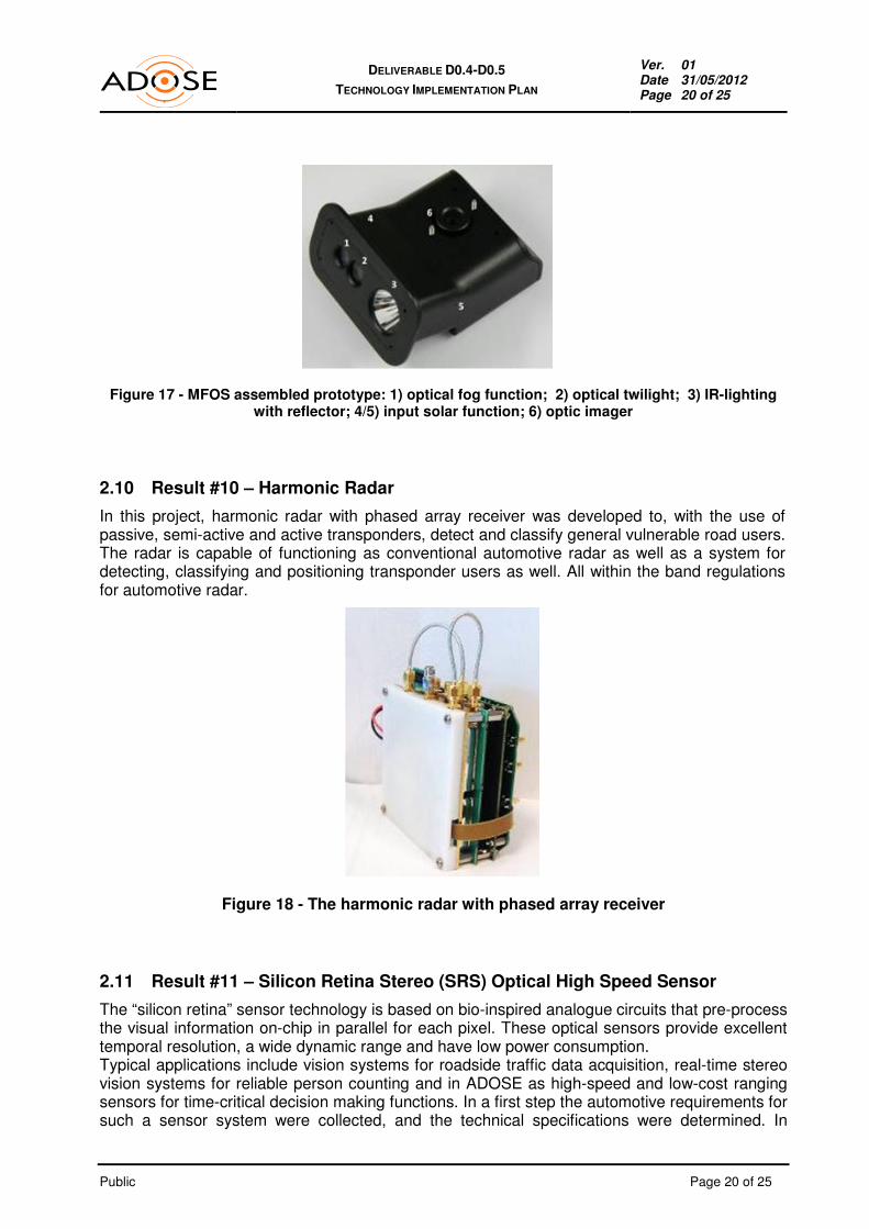
2.10 Result #10 – Harmonic Radar
In this project, harmonic radar with phased array receiver was developed to, with the use of passive, semi-active and active transponders, detect and classify general vulnerable road users. The radar is capable of functioning as conventional automotive radar as well as a system for detecting, classifying and positioning transponder users as well. All within the band regulations for automotive radar.
Figure 18 - The harmonic radar with phased array receiver
2.11 Result #11 – Silicon Retina Stereo (SRS) Optical High Speed Sensor
The “silicon retina” sensor technology is based on bio-inspired analogue circuits that pre-process the visual information on-chip in parallel for each pixel. These optical sensors provide excellent temporal resolution, a wide dynamic range and have low power consumption. Typical applications include vision systems for roadside traffic data acquisition, real-time stereo vision systems for reliable person counting and in ADOSE as high-speed and low-cost ranging sensors for time-critical decision making functions. In a first step the automotive requirements for such a sensor system were collected, and the technical specifications were determined. In

Public Page 21 of 25
DELIVERABLE D0.4-D0.5
TECHNOLOGY IMPLEMENTATION PLAN
Ver. 01 Date 31/05/2012 Page 21 of 25
ADOSE the stereo high resolution (304x240 Pixel) SRSS will be used as a pre-crash sensor for side-impact airbags control. Novel algorithms based on locality and timely correlation of asynchronous data streams have developed in order to fully exploit the advantages of the silicon retina technology for safety-critical automotive applications. The final stereo matching and detection algorithms achieved in this project are capable to work with the short baseline down to 15 cm (45 cm of the first laboratory prototype). The final demonstrator is able to show functionality of novel time-space stereo matching technique.
Figure 19 - Final demonstrator prototype
Figure 20 - Final commercial SRS system concept
The interior of demo vehicle was modified to allow integration of a fixed Rack-Mounting system. The demonstrator was installed in the inside of the vehicle at the rear window. At the final demonstration the output of the 3D Algorithm could be shown in Real-Time.
Figure 21 - Ait vehicle demonstrator
Figure 22 - SRS sensor integration on vehicle
Silicon Retina Stereo sensor mounted on the demonstration vehicle at the final review.

Public Page 22 of 25
DELIVERABLE D0.4-D0.5
TECHNOLOGY IMPLEMENTATION PLAN
Ver. 01 Date 31/05/2012 Page 22 of 25
3. INDUSTRIAL PERSPECTIVES
3.1 Automotive market
Two groups of scenarios were selected in ADOSE, depending on the restrictions imposed by the sensor types, timing constraints, sensor appliance and interaction with the ego-vehicle only:
� Collision avoidance
� Pre-crash warning/preparation Driving environments are either urban or extra-urban. The selected scenarios (with the responsible partner) are as follows:
� Group 1, Collision avoidance:
� 1.1 Collision Avoidance Extra-Urban Areas incl. VRUs (BOSCH)
� 1.2 Collision Avoidance Urban Areas incl. VRUs (BOSCH)
� Group 2, Pre-crash warning/preparation:
� 2.1 Pre-Crash Warning/Preparation Front Impact (CRF)
� 2.2 Pre-Crash Warning/Preparation Side Impact (ARC)
� 2.3 Pre-Crash Warning/Preparation Rear Impact (MMSE)
3.2 Non-automotive markets
In this section, some considerations regarding the industrial perspectives related to the integration for some non-automotive markets of the ADOSE exploitable results are presented. Further details can be found in the exploitation plans (table B3), section market analysis.
3.2.1. Building inspection
As current thermography cameras occupy price ranges that are only acceptable for experts the market is small today. With the availability of low-cost FIR imager and optics, a complete new market for low-cost thermography may be opened, offering fairly priced devices to craftsmen and even do-it-yourselfers. 3.2.2. Process control
Low-cost FIR imagers have potential in industrial applications like process control. Many processes operate with best efficiency in a temperature range close to dangerous temperatures, so remote temperature control may improve them. 3.2.3. Low cost security and surveillance
In security and surveillance applications FIR cameras are already in use. But like in other markets, the high cost of current high performance systems restricts the market volumes. Especially for automatic surveillance systems where no high quality imager representation to a human is needed, low-cost FIR imagers may enable a much larger market.

Public Page 23 of 25
DELIVERABLE D0.4-D0.5
TECHNOLOGY IMPLEMENTATION PLAN
Ver. 01 Date 31/05/2012 Page 23 of 25
The results achieved by STM on the development of the CMOS imager can also be applied to the security domain, industrial or home, where there is high demand of low cost / high resolution sensors. The development of the harmonic radar enables detection/identification personnel equipped with special coded tags which can be used in perimeter control/access applications.
4. EXPLOITATION STRATEGIES
4.1 Preparing for a cross-sector deployment activities
Partners from relevant European organisations have contributed to the ADOSE work, either by specifying requirements, developing software, hardware, demonstrator vehicles, sensors and complete systems. These achievements have been tested in the final project test site.
In this regard ADOSE made a link with other EC projects in order to discuss and share a common vision about how new sensor technologies can impact next generation safety systems. A highlight was the ADOSE Concertation Workshop in context of IV 2011 Symposium (June 5-9) in Baden-Baden (Germany). The workshop comprised contributions from 12 research projects and two open discussion sessions on sensor technologies and safety systems. The aim of the workshop that will be pursued beyond the project running is to create synergies among technology oriented projects and application/system oriented ones focusing on priorities and needs at functional, performance and cost level of safety systems.
4.2 Dissemination of ADOSE results during the project
A multi-annual dissemination roadmap and plan is included in D8.3 deliverable report focused on Dissemination and Use Plan. That report was updated all through the course of the project, leading to the final Technology Implementation Plan. The project dissemination was done during the project at several national and international events, conferences, workshops and seminars. The basic dissemination documents can be downloaded from the website (http://www.adose-eu.org/): project logo, factsheet, presentation, leaflet, etc.
Overall, ADOSE was presented at 26 events in 2010, and at least 12 done in 2011, seven papers and four articles in 2010, 13 papers or presentations and 6 articles in 2011, adding up to more than 40 over project duration. First contacts for joint workshops were started at the ICT Transport Concertation Meeting 2008, further informal meetings took place 2009 at exhibitions and events dealing with vehicular technology and transportation management (COOPERS, CVIS). It was planned and executed at ITF 2010 Leipzig to achieve synergies by participating as a consortium with a joint ADOSE Booth Spring 2010. This event addressed policy makers and high ranked officials as well as operators and OEMs.

Public Page 24 of 25
DELIVERABLE D0.4-D0.5
TECHNOLOGY IMPLEMENTATION PLAN
Ver. 01 Date 31/05/2012 Page 24 of 25
ADOSE was present at IV 2011 in Baden-Baden, Germany. IV 2011 is a focussed international event (conference and exhibition) on intelligent vehicles and the underlying technologies. ADOSE attended this event with:
• Exhibition Booth (5-9 June 2011): ADOSE was represented by a joint consortium exhibition booth demonstrating the low cost and efficient sensor technologies developed for the “virtual safety belt” of automotive vehicles.
• Concertation Workshop (5 June 2011, full day): “ How can new sensor technologies impact next generation safety systems?”
ADOSE organized the above mentioned WORKSHOP as a concertation workshop involving related European projects presenting and discussing different approaches and technologies to achieve best results by cost-effective and technically mature solutions for automotive safety. Two sessions (half day each, with intensive discussions) were performed: (1) Sensor technologies and (2) Safety systems. 12 research projects were involved: ADOSE, ICU, 2WIDE-SENSE, MISPIA, MINIFAROS, MOSARIM, FNIR, WATCH-OVER, INTERSAFE-2, interactIVe, HAVE-IT, ActiveTest. All presentations are available on the public ADOSE web site www.adose-eu.org .
A final demonstration was done in connection with the final review (Nov. 16-17, 2011, Torino). The demonstration was held at the Centro Sicurezza test track with two vehicle demonstrators integrating: (a) MFOS and FIR cameras for Warning Night Vision and (b) SRS sensor for side pre-crash applications. A video summarising the project results will be available on the ADOSE website.
4.3 Promotion of ADOSE results after project end
Although ADOSE will continue to use the same printed materials such as flyers, brochures, the principal channel for communication will be the public website www.adose-eu.org (or new address), which will remain active to provide a read access to the:
• public deliverables;
• publications (papers and articles);
• other dissemination material (e.g. brochures, flyers, banner);
Moreover, a video focused on the final demonstration will remain downloadable to bring the work to a wide audience and give a strong modern image to all dissemination activities.

Public Page 25 of 25
DELIVERABLE D0.4-D0.5
TECHNOLOGY IMPLEMENTATION PLAN
Ver. 01 Date 31/05/2012 Page 25 of 25
5. CONCLUSION
This final Exploitation plan sets out the partners’ intentions for the exploitation and implementation of the project results, both individually and collectively, beyond the end of the project. Communication and dissemination activities are crucial in promoting knowledge sharing, awareness and understanding of the ADOSE exploitable developments.
In order to make ADOSE household name and generate bottom-up demand for relevant products, the different stakeholders involved need to have a clear and common understanding of the benefits that such systems can bring them.
The present document sets forth the strategies and measures to be employed by the ADOSE partners in order to exploit and promote the ADOSE results after the project end.
The present document D0.4-D0.5 – “Technological Implementation Plan” provides a public overview of the exploitation results, together with a confidential detailed plan for exploitation or use in further research for the individual exploitable achievements.
6. ANNEX - LIST OF FIGURES AND TABLES
Figure 1 - Challenges regarding ADAS sensors addressed in ADOSE ............................................................. 5
Figure 2 - Potential ADAS applications addressed by ADOSE sensors ............................................................ 7
Figure 3 - Overall results of the technological implementation, in relationship with the ADOSE architecture ... 9
Figure 4 - FIR camera demonstrator ................................................................................................................ 13
Figure 5 - Chip-on-board assembly of an imager chip ..................................................................................... 13
Figure 6 - Image with native resolution ............................................................................................................ 14
Figure 7 - Image with bicubic interpolation ....................................................................................................... 14
Figure 8 - Image with bicubic interpolation ....................................................................................................... 14
Figure 9 - Wafer level moulding of IR lenses ................................................................................................... 14
Figure 10 - Integration of microlenses and Bayer filter in the CMOS imager ................................................... 15
Figure 11 - Modified OLGA package ................................................................................................................ 16
Figure 12 - Active tag integrated into an optical reflector ................................................................................. 16
Figure 13 - Varactor-based sensor prototype ................................................................................................... 17
Figure 14 - Radar ECU software ...................................................................................................................... 18
Figure 15 - Outdoor test of MFOS sensor (fog, tunnel and warning night vision). ........................................... 19
Figure 16 - MFOS camera prototype integrated in the internal rearview mirror ............................................... 19
Figure 17 - MFOS assembled prototype: 1) optical fog function; 2) optical twilight; 3) IR-lighting with reflector; 4/5) input solar function; 6) optic imager ........................................................................................... 20
Figure 18 - The harmonic radar with phased array receiver ............................................................................ 20
Figure 19 - Final demonstrator prototype ......................................................................................................... 21
Figure 20 - Final commercial SRS system concept ......................................................................................... 21
Figure 21 - Ait vehicle demonstrator ................................................................................................................ 21
Figure 22 - SRS sensor integration on vehicle ................................................................................................. 21
Table 1 - ADOSE specifications ....................................................................................................................... 15