adp-1 liner panel - behlen building systems · 2017-08-25 · adp-1 liner panel erection guide ....
TRANSCRIPT

ADP-1 LINER PANEL ERECTION GUIDE
NOTE: See back side of cover for latest changes to this manual. BEHLEN MFG. CO. COLUMBUS, NE 68601 TECHNICAL INFORMATION 55062 Rev. 8/23/12

NOTE: If pink sheets are included in this manual, refer to them for latest revisions. LATEST CHANGES BY: TK DATE: 8/23/12
PAGE CHANGE 8 Removed two letter code from significant part.

FRAME BUILDING LINER TABLE OF CONTENTS
1
TITLE OR DESCRIPTION PAGE NUMBER General Information ............................................................................................................................... 2-5 Liner at Base ......................................................................................................................................... 6 Liner at Girts .......................................................................................................................................... 7 Liner at Eave Struts ............................................................................................................................... 8 Liner at Rake ......................................................................................................................................... 9 At Columns By-Pass Girts ..................................................................................................................... 10 At Corners By-Pass Sidewall/Endwall Girts .......................................................................................... 11 & 12 At Columns – 1” Projection – Flush Girts .............................................................................................. 13 At Columns – 0” Projection – Flush Girts .............................................................................................. 14 At Corners Flush Girt ............................................................................................................................. 15, 16, & 17 Liner At Ceiling ...................................................................................................................................... 18, 19 & 20 Liner At Self-Framing Window ............................................................................................................... 21 Liner At Preassembled Window ............................................................................................................ 22 Liner At Knocked-Down Door ................................................................................................................ 23 Liner At Preassembled Door ................................................................................................................. 24 Liner At Walk Door Rough Frame ......................................................................................................... 25 Liner At Framed Opening ...................................................................................................................... 26 & 27 Liner At Framed Opening With Sill ........................................................................................................ 28 & 29
11/5/04

GENERAL INFORMATION
2
The erection information presented herein is provided as a supplement to the erection drawings prepared for your specific job. The information, illustrations and procedures in this guide are typical for most Behlen buildings. Variations may occur because of special building requirements. Always refer to the erection drawings supplied with each job which will govern specific part and assembly arrangements and applicable illustration details. Because Behlen products are constantly being improved, the information contained herein is subject to change without notice. The following fastener schedule is to be used with this erection guide and will correspond to the fastener schedule in the erection drawings supplied with each job.
FASTENER SCHEDULE Loc. Part No. Description
b As Noted On Rigid-Frame Elevation
c 3228100 Screw ¼ x 3/4 FL-TP SD WW
d 3228084 Screw 12 x 1 HWH SD NW
e 3228101 Screw 12 x 1-1/4 FL-TP SD WW
f 3228105 Screw ¼ x 1-1/4 LG-LF SD WW
g 3228099 Screw 8 x ½ HWH SD NW
h 3188185 Bolt ½ x 1 ¼ HexA307 UNPL and Nut (2688126)
i 3188186 Bolt ½ x 1 ¾ Hex A307 UNPL and Nut (2688126)
j 3188130 Bolt 5/8 x 2-1/4 HVHX A325T UNPL and Nut (2688101)
1) 3188121 Bolt ¾ x 1-1/2 HVHX A325T UNPL and Nut (2688102)
1! 3188125 Bolt ¾ x 2-1/2 HVHX A325T UNPL and Nut (2688102)
1@ 3228100 Screw ¼ x 3/4 FL-TP SD WW for ADP-1 Roof 3228103 Screw ¼ x 3/4 LG-LF SD WW for SSR
1# 3228101 Screw 12 x 1-1/4 FL-TP SD WW for ADP-1 Roof 3228104 Screw 12 x 1-1/4 LG-LF SD WW for SSR
1$ 3228087 Screw 12 x 1-1/4 HWH SD #5PT NW
1% 3188223 Bolt ½ x 1-1/2 HVHX A325T UNPL and Nut (2688137)
1^ 3208170 Bolt ½ x 1 FLT RD HD A307 PLTD and Nut (2688007)
1& 3228102 Screw 12 x 2 FL-TP SD WW
1* 3228098 Screw 14 x 6 HWH ST 304 SS NW
ERECTION INFORMATION Liner panel sidelaps shall be stitched together with a c fastener at 24” centers.
Abbreviations HD = Head SD = Self-Drilling ST = Self-Tapping SS = Stainless Steel PT = Point RD = Round WW = With Washer NW = No Washer FLT = Flat HVHX = Heavy Hex UNPL = Unplated PLTD = Plated HWH = Hex Washer Head FL-TP = Flat Top LG-LF = Long Life
9-25-06

GENERAL INFORMATION
3
STOP . . . PLEASE READ RECOMMENDED INSTALLATION FOR SELF-DRILLING TAPPING FASTENERS TO INSURE FASTENER PERFORMANCE. * Apply with 1800 RPM electric screw gun. * Drive socket size must fit appropriately to fastener head. Socket Types:
1. Super Star Socket - Used for long-life non-magnetic screw heads. Can be used with carbon screw to avoid drill chips collecting on magnetic sockets.
Inland Part No. - 1/4” (3518045) 5/16” (3518046) 3/8” (3518047)
2. Non-magnetic - Used by erectors on roofing applications, mainly to avoid drill chips collecting in sockets.
Special Order - 1/4” 5/16” 3/8”
Drilling/Driving fastener must be held perpendicular to the fastening surface. Self-Drilling fasteners should not be forced in. Allow the drill point to do the work.
- CAUTION - Over-torquing may result in fastener separation/failure (head popping off). Care should be exercised during installation. Torque of 30-60 in. lbs. Based on fastener size and application.
FOR APPLICATION SUPPORT, CONTACT: ATLAS BOLT & SCREW TECHNICAL SERVICES (800) 321-6977
Inland Buildings (800) 438-1606 *1800 RPM screw guns and sockets are available at your local tool house or from: Dynamic Fasteners 1-800-821-5448
11/5/04

GENERAL INFORMATION
4
HANDLING LONG TRIM COMPONENTS When removing long trims from the shipping crate and during installation, care should be taken by construction workers to avoid damage caused by buckling.
PROTECTIVE FILM REMOVAL The trim components received with this building have a protective film on the colored surface that must be removed prior to installation. Prolonged exposure (more than 3 weeks) to rain and/or sunlight will adversely effect the protective film making removal difficult. When film is being removed from trim having a hem along its edge, the film should be peeled off along the entire end. This includes the 3/8” hemmed area on the back side. Pull the entire film strip at a constant rate. Do NOT try to rip the film off as it will tend to tear at the hemmed edge and corners leaving a strip that will have to be removed separately.
11/5/04

GENERAL INFORMATION
5
RELATIONSHIP OF LINER PANEL AND EXTERIOR PANEL RIBS Liner panels for a complete sidewall or endwall surface have been detailed with a process similar to the exterior wall panels. The location of the liner panels is based on the length of the exterior wall surface and whether there is a “Start Dimension” at each end of the wall surface. This detailing process will keep the liner panel ribs and the exterior panel ribs in line.
During the erection process, the sidewall liner panel locations may start or stop at J-trims as desired but on the endwall surface, the liner panel length may be insufficient if moved to some other location.
11/8/99

LINER AT BASE
6
8-25-00

LINER AT GIRT
7
12/17/03
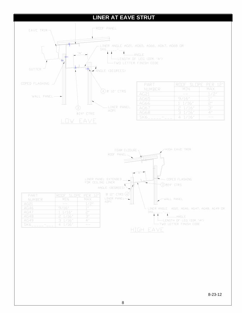
LINER AT EAVE STRUT
8
8-23-12

LINER AT RAKE
9
10/14/05

LINER AT COLUMNS – BY-PASS GIRTS
10
12/17/03

LINER AT CORNER – BY-PASS SIDEWALL/ENDWALL GIRTS
11
12/17/03

LINER AT CORNER – BY-PASS SIDEWALL/ENDWALL GIRTS
12
12/17/03

LINER AT COLUMN – 1” PROJECTION – FLUSH GIRTS
13
12/17/03

LINER AT COLUMN – 0” PROJECTION – FLUSH GIRTS
14
12/17/03

LINER AT CORNER – FLUSH SIDEWALL/ENDWALL GIRTS
15
1 INCH GIRT PROJECTION
12/17/03

LINER AT CORNER – FLUSH SIDEWALL/ENDWALL GIRTS
16
0 INCH GIRT PROJECTION
12/17/03
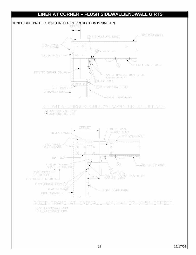
LINER AT CORNER – FLUSH SIDEWALL/ENDWALL GIRTS
17
0 INCH GIRT PROJECTION (1 INCH GIRT PROJECTION IS SIMILAR)
12/17/03

LINER AT CEILING
18
12-17-03
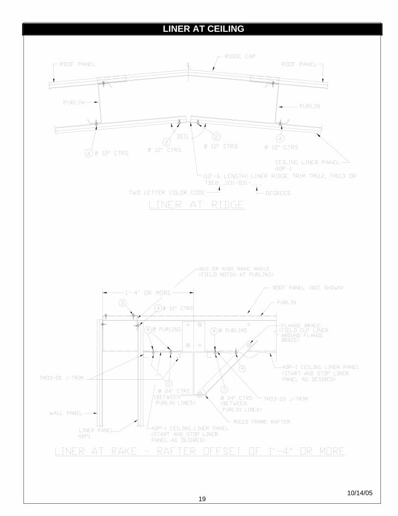
LINER AT CEILING
19
10/14/05

LINER AT CEILING
20
10/14/05

LINER AT SELF-FRAMING WINDOW
21
11/8/99

LINER AT PREASSEMBLED WINDOW
22
12/17/03

LINER AT KNOCK-DOWN DOOR
23
7/21/06

LINER AT PREASSEMBLED DOOR
24
3/22/07

LINER AT WALK DOOR ROUGH FRAME
25
12/17/03

LINER AT FRAMED OPENING
26
HEADERS NEAR EAVE STRUTS
HEADERS BELOW SIDEWALL / ENDWALL GIRTS AT STANDARD ELEVATIONS
11/8/10

LINER AT FRAMED OPENING
27
11/8/99

LINER AT FRAMED OPENING WITH SILL
28
11/5/04

LINER AT FRAMED OPENING WITH SILL
29
11/8/99