adrian ilie combining head-mounted andwelch/media/pdf/ilie2004_hybrid.pdf · adrian ilie kok-lim...
TRANSCRIPT

Adrian IlieKok-Lim LowGreg WelchAnselmo LastraHenry FuchsDepartment of Computer ScienceUniversity of North Carolina atChapel Hill
Bruce CairnsDepartment of SurgeryUniversity of North CarolinaChapel Hill
Presence Vol 13 No 2 April 2004 128ndash145
copy 2004 by the Massachusetts Institute of Technology
Combining Head-Mounted andProjector-Based Displays forSurgical Training
Abstract
We introduce and present preliminary results for a hybrid display system combining
head-mounted and projector-based displays Our work is motivated by a surgical
training application where it is necessary to simultaneously provide both a high-
fidelity view of a central close-up task (the surgery) and visual awareness of objects
and events in the surrounding environment In this article we motivate the use of a
hybrid display system discuss previous work describe a prototype along with meth-
ods for geometric calibration and present results from a controlled human subject
experiment
This article is an invited resubmission of work presented at IEEE Virtual Reality
2003 The article has been updated and expanded to include (among other things)
additional related work and more details about the calibration process
1 Introduction
Today the pace of surgical innovations has increased dramatically ashave societal demands for safe and effective practices The mechanisms fortraining and retraining suffer from inflexible timing extended time commit-ments and limited content Video instruction has long been available to helpsurgeons learn new procedures but it is generally viewed as marginally effec-tive at best for a number of reasons including the fixed point of view that isintegral to the narration the lack of depth perception and interactivity and theinsufficient information that is presented (Tachakra Jaye Bak Hayes amp Siva-kumar 2000)
Apprenticeship (actually being there) can be very effective but there aresome difficult surgical procedures that are so rare and have such high mortalityrates that there is no time to assemble the students before the procedure andno time to explain what is going on during the procedure One example ofsuch a procedure is the treatment of blunt liver traumas resulting from auto-mobile accidents Such traumas occur rarely (at the UNC-Chapel Hill Hospitalthere are about five such cases per year) have to be treated immediately (theyare life-threatening) and are delicate and complex As a result it is typicallyimpractical for trainees to participate in a meaningful way
128 PRESENCE VOLUME 13 NUMBER 2
11 Immersive Electronic Books
A training paradigm that uses immersive VirtualReality could be a more effective approach since itwould allow trainees to witness and explore a past surgi-cal procedure as if they were there We are currentlypursuing such a paradigm together with our medicalcollaborators at the UNC-Chapel Hill School of Medi-cine (Bruce Cairns MD and Anthony Meyer MD)and our computer graphics collaborators at Brown Uni-versity (Andries van Dam Sascha Becker LoringHolden and Jesse Funaro) Our approach is to recordthe procedure and to reconstruct the original time-varying events in an immersive 3D Virtual Environmentthat depicts the real scene including the patient andexpert physicians augmented with relevant medical in-structions and information such as vocal narration 3Dannotations and illustrations and to display this in ahybrid display as shown in Figure 1 As part of his PhDthesis Yang (2003) constructed a research prototype(see Figure 2) and developed new methods that allow3D data capture and reconstruction Our collaboratorsat Brown University are currently working on variousmethods for annotating the captured data and creating acomplete Immersive Electronic Book (van Dam FuchsBecker Holden Ilie et al 2002)
12 Display Requirements
Besides the recording and the reconstruction pro-viding an effective way to display a 3D Virtual Environ-ment to the user is also a major challenge We envision adisplay system that can be used both by surgeons (toreview a procedure during clinical decision-making orto annotate it for training purposes) and by trainees (toobserve and learn a procedure)
The visual needs of the users are twofold The firstneed is for a high-quality stereo view of the objects andevents that the trainees are directly viewing such as themain surgical procedure as shown in Figure 3(a) High-quality and high-resolution views are needed to discernthe great intricacy of the surgery and stereo vision isneeded for better spatial understanding The secondneed is for a peripheral view of the surroundings This isneeded to maintain visual awareness of the surroundingevents as shown in Figure 3(b) Our medical collabora-tors feel that visual awareness of the entire body of thepatient and the surroundings is a critical component ofsurgical training In particular with trauma surgery
Figure 1 Henry Fuchs using a prototype of our hybrid display
Figure 2 Dr Bruce Cairns using the 3D data capture prototype
described in (Yang 2003)
Ilie et al 129
there is typically a great deal of independent but rele-vant activity in the operating room as each member ofthe surgical team attends to the patient monitoring ma-chines change state and so on In virtual environmentsthis type of visual awareness needs to be provided for bya display that covers the userrsquos peripheral view How-ever because the effective resolution in the periphery ofthe human vision system is less dense than that of thefoveal region (Davson 1990) this peripheral displayneed not be as high-resolution and high-quality
Traditionally head-mounted displays (HMDs alsocalled head-worn displays) have been used to providehigh-quality stereo visualization of 3D Virtual Environ-ments However most HMDs offer limited fields ofview (FOV) typically within the range of 40deg to 60deghorizontally and 30deg to 45deg vertically Very wide FOVHMDs have been prototyped but they are rare expen-sive and cumbersome to wear (Kaiser Electro-OpticsInc 2000) We are aware of no readily available HMDthat can fully cover the human FOV of approximately200deg horizontally and 135deg vertically (Werner 1991)Although HMDs are good at providing high-qualitystereo views their typically narrow FOVs make themless than ideal for providing peripheral views Commonalternatives to HMDs are projector-based displaysmdasheither immersive displays such as the CAVE (Cruz-Neira Sandin amp DeFanti 1993) or planar displayssuch as the Responsive Workbench (Kruger BohnFrohlich Schuth Strauss et al 1995) Most projector-based displays are capable of providing very wide FOV
visualization and some of them like the CAVE areeven capable of fully covering the human FOV How-ever because the display surfacesmdashwhich are relativelylargemdashare typically covered by only one projector andbecause the user may move close to the surfaces theimage quality and resolution of such projector-basedsystems may be insufficient for applications that requirefine detail
13 Our Approach (Hybrid Display)
We decided that neither HMDs nor projector-based displays alone could meet the visual needs of asurgical trainee However we noticed potential advan-tages that could be exploited in each display systemespecially the high-resolution stereo view in HMDs andthe wide FOV in projector-based displays These com-plementary characteristics led us to a hybrid approachthat enjoys both a high-resolution stereo view throughthe HMD and a lower-resolution peripheral view fromprojectors We believe this hybrid approach can effec-tively satisfy the visual needs of a surgical trainee
As a proof of concept and a means of investigationwe implemented a simple prototype of the hybrid dis-play system (see Figure 1) To quantify its effectivenessin combining the useful attributes of both the HMDand the projector-based display we also conducted ahuman subject experiment The preliminary results ob-tained from the experiment support our belief that thehybrid display is suitable for applications like 3D immer-sive surgical training which involve visual tasks that re-quire both up-close detail and peripheral awareness
14 Contributions
The main contribution of this work is conceivingarticulating and prototyping a hybrid display system thatleverages the complementary merits of head-mounted andprojector-based displays A second contribution is our con-trolled human subject experiment which offered somesurprising (to us) results and valuable support to the ideaFinally we also introduce a new approach that uses periph-eral vision to calibrate opaque HMDs
Figure 3 Two different views of a surgical operation
130 PRESENCE VOLUME 13 NUMBER 2
15 Paper Organization
In the next section we look at some previous workrelated to our hybrid display In section 3 we offer a de-tailed description of the hybrid display and our simple pro-totype and include a discussion of the advantages draw-backs and implementation issues of the hybrid display Insection 4 we outline the calibration process including ournew opaque HMD calibration method In section 5 wedescribe our human subject experiment and present andanalyze its results Finally in section 6 we share some clos-ing thoughts
2 Related Work
Previous research related to our hybrid display proto-type system lies in three main areas corresponding to thetwo components of the prototype (projector-based dis-plays and HMDs) and to other hybrid displays The nextsubsections summarize relevant contributions in the threeareas
21 Projector-Based Displays
The CAVE (Cruz-Neira Sandin amp DeFanti 1993)is probably the most commonly cited example of a gener-al-purpose projector-based display system for immersivevirtual reality and scientific visualization A CAVE usuallyconsists of a cube (several meters on a side) made of rear-projection screens for the walls and the ceiling and adown-projection screen for the floor It is capable of pro-viding stereo imagery to the user typically using a time-multiplexing approach that alternates images for the leftand right eyes
Another popular and successful paradigm is that of theResponsive Workbench (Kruger Bohn Frohlich SchuthStrauss et al 1995) It consists of a back-projected planardisplay on which one or two time-multiplexed users canvisualize stereo images It provides an effective means ofinteracting with virtual environments for some applicationsand is easier to deploy than a CAVE Like the CAVE ithas been widely used in research laboratories around theworld
Other approaches for projector-based displays have alsoemerged such as the work described by Raskar BrownYang Chen Welch et al (1999) that aims at reconfigu-rability color uniformity and seamlessness In this worknon-planar display surfaces are casually arranged thencameras are used to simultaneously calibrate the projec-tors and display surfaces to allow correct display of view-dependent (head-tracked) imagery at run time
The projector-based component of our hybrid displaybuilds on our previous work on life-sized projector-based dioramas (Low Welch Lastra amp Fuchs 2001)That work is a more general effort aimed at creatinglife-sized immersive virtual environments of real orimagined places The basic idea is to size and arrangephysical projection surfaces to roughly approximate thereal geometry in the virtual environment providingboth visual and spatial realism
There have been attempts to incorporate high-resolution insets into projector-based displays Themost notable are the Escritoire (Ashdown amp Robinson2003) a front-projected desk surface that uses twooverlapping projectors to create a foveal display thatcontains a high-resolution area and Focus Plus Contextscreens (Baudisch Good amp Stewart 2001) which usean embedded LCD for the same purpose They are ex-tensions of the desktop metaphor to a large display andusers need to move objects to the high-resolution area ifthey want to visualize their details Other approacheswith applications closer to Virtual Reality are repre-sented by the Link ESPRIT flight simulator (DugdaleFortin amp Turner nd) and the Sogitec APOGEE simu-lator family (Hurault 1993) which use the pilotrsquos headandor eye movements to guide a high-resolution pro-jected area-of-interest on a larger low-resolution pro-jected display
22 Head-Mounted Displays
HMDs have been used as a means to display im-mersive Virtual Environments for the last three decades(Sutherland 1968) Research related to HMDs hasgenerally concentrated on improving the resolutionand the optics and minimizing negative effects such
Ilie et al 131
as cybersickness (nausea) The Kaiser Full ImmersionHead-Mounted Display (FIHMD) (Kaiser Electro-Optics 2000) achieves wide FOV by tiling multiplescreens to form the display The FIHMD contains 12LCD placed in a 32 arrangement for each eye It pro-vides a total FOV of approximately 176deg horizontallyby 47deg vertically Unfortunately as far as we know thissystem was a one-time prototype and is unavailable forpurchase
Research more closely related to our work includesattempts to incorporate peripheral vision into HMDsWhitestone and Robinette (1997) concluded that thisessentially means increasing the FOV of HMDs whichtranslates into an increase in the size and resolution ofthe display screen an increase in the diameter of thelens or a decrease in the focal length In 1979 EricHowlett designed the Large Expanse Enhanced Per-spective (LEEP) Optics (LEEP Systems 1996) whichused spherical lenses and square screens 69 mm on aside to build an HMD with a 90deg FOV Images wereoptically predistorted using special lenses attached tocameras that imaged regular CRT displays and then thedistortion was reversed by the optics of the HMDSlater and Usoh (1993) simulated a wider FOV usingdistortion of the displayed images in a way that com-pressed more of the scene into the outer regions of thedisplay area The foveal region of the display was ren-dered normally while in the periphery a larger-than-normal portion of the FOV was imaged by adding ashear to the projection A similar approach is to renderhigh-resolution images in a small area-of-interest andlow-resolution images elsewhere Toto and Kundel(1987) and Yoshida Rolland and Reif (1995) con-structed area-of-interest HMDs with eye-tracking sys-tems that render the high-resolution inset to where theeye is looking at a given time Watson Walker Hodgesand Reddy (1997) argued that there is no significantdecrease in performance if the inset is fixed since typicaleye movements do not go farther than 15deg from thefovea
In his PhD dissertation Arthur (2000) provides amuch more detailed overview of numerous attempts toincorporate peripheral vision into HMDs
23 Hybrid Displays
In 1991 Feiner and Shamash introduced the idea ofhybrid displays as a way to move beyond the (then) con-ventional one-userone-display metaphor They demon-strated a prototype hybrid display that used a see-throughHMD to provide low-resolution context via visually over-laid imagery and a fixed flat-panel display (viewed throughthe HMD) to provide high-resolution information Othershave since added low-fidelity displays to a conventionalHMD to provide peripheral information with apparentsuccess For example the Ambient HMD project atMonterey Technologies has shown that adding peripheralLCD displays improves performance in a helicopter simu-lator (Monterey Technologies 1999) At CeBIT 2002researchers from the Fraunhofer Heinrich-Hertz Institutedemonstrated a prototype visualization workstation thatcombines a central autostereoscopic 3D display with sur-rounding 2D displays (Pastoor amp Liu 2002) The systemis designed to allow a seated user to visualize 3D imageryin a (fixed) central region and conventional 2D computerldquodesktoprdquo imagery to the left and right The system alsoincludes gesture-recognition technology that allows a userto drag objects back and forth between the 2D and 3Ddisplay areas
3 A Hybrid Head-Mounted andProjector-Based Display
Our hybrid display combines an HMD and aprojector-based display The idea is to address the visualneeds of a user of the 3D immersive surgical trainingsystem by leveraging the complementary merits andshortcomings of HMDs and projector-based displays
We have implemented a prototype as a proof of theconcept In this prototype we use a Kaiser ProView 30stereo HMD (Kaiser Electro-Optics 2000) which doesnot have baffling material around the displays thatwould block the wearerrsquos peripheral view of the realphysical world (see Figure 4) This allows users of theprototype to also see peripheral imagery projected ondisplay surfaces around them
Ideally to completely cover the peripheral vision of a
132 PRESENCE VOLUME 13 NUMBER 2
user the projector-based display should surround theuser even above and below as in a CAVE Instead forour prototype and user study we have built only a par-tial surround-display as shown in Figure 5 The displaysurfaces were constructed using vertically stacked whiteStyrofoam blocks and a horizontal piece of white foam-reinforced cardboard When in use four projectors
project view-dependent imagery on top of the card-board and on the vertical Styrofoam wall In the spirit oflife-sized projector-based dioramas (Low Welch Lastraamp Fuchs 2001) the horizontal cardboard surface corre-sponds to a surgical table in the virtual operating roomBesides providing the user with a stronger sense of spa-tial connection between the real and virtual environ-ments the main purpose of the horizontal cardboardsurface is to increase the userrsquos vertical FOV when theuserrsquos head is directly above the table
When a user is standing at the center of the display(approximately 65 cm from the Styrofoam wall whichcorresponds to a location where a user would usuallystand in the virtual environment) the projector-baseddisplay has a FOV of approximately 130deg horizontallyand 120deg vertically (see Figure 6 not drawn to scale)In comparison to the FOV of the Kaiser HMD which isonly 24deg horizontally and 18deg vertically we believed theprojector-based display was wide enough to offer im-provement over the HMD alone
For the first prototype we created a simplified syn-thetic model of an operating room with a virtual patientlying on the surgical table and three virtual surgeonsnurses moving around near the table (see Figure 1)Periodically one of the virtual surgeonsnurses wouldextend its arm toward the center of the table mimickinga real nurse handing a surgical tool to a surgeon duringa real surgical procedure When we tested the prototypeourselves we would attempt to act in the way a surgicaltrainee would when using an actual training system We
Figure 4 A user wearing the HMD component of our prototype
hybrid display with an attached HiBall tracker sensor (Welch et al
2001)
Figure 5 The projector-based component of our prototype hybrid
display
Figure 6 The layout of the hybrid display components to cover the
userrsquos FOV
Ilie et al 133
tried to concentrate on the virtual patientrsquos abdominalarea and maintain awareness of the movements of thevirtual surgeonspatients around us For comparisoneach of us had opportunities to try two different setupsone with the use of both the HMD and projectors (thehybrid) and another with the use of the HMD aloneFor the HMD-only setup the projectors were switchedoff and the laboratory was kept dark
After having experienced the two setups every one ofus felt that the hybrid display setup made it much easierto maintain awareness of the movements of the virtualsurgeonsnurses while concentrating on the patientrsquosabdominal area In contrast with the HMD-only setupit was almost impossible to know the positions of thevirtual surgeonsnurses without frequently turning ourheads to scan the surroundings Based on these informalpreliminary findings we decided to undertake a moreobjective formal human subject experiment We de-scribe this experiment in section 5
Besides serving as a means to investigate and demon-strate the effectiveness of the hybrid display approachanother objective of the prototype was to identify orconfirm potential limitations and implementation issuesThese limitations and implementation issues as well asthe advantages of the approach are discussed in the fol-lowing subsections
31 Advantages
Through the HMD a hybrid display can achievehigh resolution that is arguably hard to match by anyimmersive projector-based display Thanks to theHMD the user of the hybrid display can selectivelyincrease the image details of any part of the virtualenvironment by moving closer to it This directly cor-responds to what a person would naturally do in thereal world Projector-based tiled displays (Li ChenChen Clark Cook et al 2000 Raij Gill Majum-der Towles amp Fuchs 2003) have long been used todisplay high-resolution images however their use forour application would be relatively inefficient as usersdo not need high resolution everywhere around themat the same time
As mentioned before the hybrid display includes atraditional immersive projector-based surround displayallowing it to cover the entire visual field of the userHowever because the users only view the projected im-agery in their periphery that projected imagery can berelatively low-resolution This means fewer projectorsare needed overall Moreover since the responsibility toprovide stereo vision is already taken over by the HMDthere is no need for stereo projection This offers furthersavings in terms of the number of projectors and re-quired rendering resources
With a hybrid display there is no need to use a wide-FOV HMD which would typically be very expensive andcumbersome Instead a cheaper smaller and less cumber-some HMD can be used A narrower FOV in the HMDalso allows some rendering acceleration techniques such asview frustum culling to be more effective
In summary for our application we believe that ahybrid display can be a more versatile cost-effectiveefficient and functionally effective approach than eitheran HMD or a projector-based system alone
32 Drawbacks Limitations and Issues
One drawback to our hybrid approach is thatusers still have to wear an HMD on their headswhich sometimes can be cumbersome However be-cause the HMD does not need to be wide-FOV anddoes not have baffling material around the display itcan be made smaller and lighter more easily We alsonote that even users of immersive projector-baseddisplay systems typically have to wear something ontheir headsmdashstereo glasses and tracking devices
An artifact that we have noticed in practice is the darkborder (opaque frame) around each of the HMDrsquos dis-plays As with any Augmented Reality application suchborders break the continuity between the central(HMD) and peripheral (projected) views Our experi-ence is that for commercial systems available todaythese borders tend to be relatively thick For our HMDin particular we estimate that each vertical segment ofthe border is approximately 7deg wide and each horizon-tal segment is approximately 12deg tall We did not per-
134 PRESENCE VOLUME 13 NUMBER 2
form any experiments to investigate how these bordersaffect a userrsquos performance or sense of presence
There is an overlap region between the left and righteyes that forms the human stereo visual field (Davson1990) This stereo visual field spans almost the entirevertical FOV of the eyes In our hybrid display proto-type much of the userrsquos stereo visual field is outside theHMD and is served by non-stereo projected imageryfrom the projectors We consider this an important issuefor further investigation
A further limitation of a hybrid system using anopaque HMD is that users cannot see their own handswhen they are manipulating virtual objects in front ofthe HMD To address this problem some researchershave developed methods to incorporate real objectssuch as the userrsquos hands into the virtual environmentsOne such method is described by Lok (2001) Lok alsopresents a comprehensive survey of other work in thearea Fortunately the users of our hybrid display systemcan still see their bodies and legs in the peripheral viewWe believe this helps significantly when the users arenavigating in the virtual environment As part of futurework we plan to investigate the use of a see-throughHMD in the hybrid display To address occlusion con-flicts between the userrsquos hands (or other real objects)and the virtual objects we would need either real-timehand tracking or dynamic 3D hand models such as theones obtained using Lokrsquos approach
There are also other issues that are inherent in the useof projector-based displays such as intensity blending atoverlapping regions color uniformity across differentprojectors and back-projection versus front-projectionWe refer the reader to Low Welch Lastra and Fuchs(2001) and Raskar Brown Yang Chen Welch et al(1999) for further details
Finally because the HMD and projected images orig-inate at different distances from the eyes users mightexperience accommodation or focus difficulties if theyattempt to rotate their eyes back and forth betweenHMD and projected imagery While we believe the us-ers of our system would primarily use the projected im-agery for peripheral awareness only we consider this animportant area warranting further investigation
4 Construction Calibration and SystemConfiguration
To create a hybrid HMD-Projector display systemwe first establish a global coordinate frame using ourtracking system Afterward we plan and arrange theprojectors and physical display surfaces as in LowWelch Lastra and Fuchs (2001) and calibrate the pro-jector(s) and the HMD These steps are described in thefollowing subsections The resulting view from a userrsquosperspective is shown in Figure 7 (photographed with afish-eye-lens camera placed inside the HMD) The hard-ware and software configuration of our prototype is de-scribed in section 45
41 Global Coordinate Frame
To ensure that the combined imagery presented tothe user is contiguous we establish and use a singleglobal coordinate system (virtual world coordinates)throughout the calibration process To establish theglobal coordinate system we compute a 3D rigid-bodytransformation between the physical tracker coordinatesand the virtual world coordinates We first choose atleast four points in the real world and measure theirtracker coordinates and then put them in correspon-dence with appropriately-chosen points in the virtualworld We then solve for the transformation using aleast-squares method described in Arun Huang andBlostein (1987) This transformation and its inverse areused later in the calibration process to transform be-tween tracker and virtual world coordinates
Figure 7 A userrsquos view of the hybrid display (highlight added)
Ilie et al 135
42 Projector and Display SurfaceArrangement
To aid with the construction of projector-baseddisplays we developed a program to allow us to manu-ally design an arrangement of projectors and surfacesthat we use afterward as a blueprint for the physicalsetup Figure 8 shows a screenshot of the program dis-playing the design we used for the human subject exper-iment detailed in section 5 (cf Figure 1) The projec-tion surfaces are outlined in white The steps of theprocess are as follows (1) we use our program to designthe projection surfaces (2) using this design weroughly arrange the physical surfaces (Styrofoamblocks) (3) we then position and orient the projectorsand adjust their focusing distances to get the best focuson the display surfaces
43 Projector Calibration
The next step is to calibrate the projectors to findtheir geometric relationships with the virtual world coordi-nate frame and the display surfaces To calibrate a projec-tor we need to find a set of pair correspondences betweenthe coordinates of 3D points in space and the coordinatesof the corresponding pixels on the projectorrsquos image plane
With six or more pair correspondences (no four coplanar3D points) we can solve for the projection parametersusing linear least-squares methods or nonlinear optimiza-tion approaches (Faugeras 1993) To find a pair corre-spondence we display a known 2D point using the projec-tor This 2D point emerges from the projector as a rayThen we move a small rigid temporary display surface tointersect the ray and use a tracker to measure the 3D posi-tion of the intersection The 3D point is then transformedfrom the tracker coordinate system into the virtual worldcoordinate system using the previously computed transfor-mation This set of pair correspondences is used to solvefor the projectorrsquos projection parameters with respect tothe virtual world coordinate system The above manualapproach to finding pair correspondences can be tediousand error-prone at times In the future we might imple-ment a procedure for automatic projector calibration usingcameras such as the one by Raskar Brown Yang ChenWelch et al (1999) possibly as part of an automated pro-jector placement algorithm
When the projectors are calibrated we project wire-frame outlines of the designed display surfaces onto thephysical surfaces to help us fine-tune and correct thephysical setup by moving the surfaces slightly to matchthe projected outlines (see Figure 9 cf Figure 8)
Figure 8 A screenshot of the design program used for arranging
the projection surfaces
Figure 9 Fine-tuning the physical setup by projecting wireframe
outlines
136 PRESENCE VOLUME 13 NUMBER 2
44 HMD Calibration
Geometric calibration of the HMD is necessary toproperly align the images seen in the HMD with theprojected imagery from the projectors While research-ers have calibrated optical see-through HMDs(Tuceryan amp Navab 2000) we are aware of no pub-lished method to calibrate an opaque HMD Here wepresent a relatively simple and novel approach thatmakes use of the userrsquos peripheral vision We divide thecalibration of each HMDrsquos display into two stages eye-point calibration and view frustum calibration
441 Eyepoint Calibration In the first stagewe find the position of the eyes in the tracker sensor coor-dinate frame (The tracker sensor is the part of the trackerthat is rigidly attached to the userrsquos head so that the sensorcoordinate frame becomes fixed with respect to the userrsquoshead) The position of each eye can be found by finding atleast two lines in the tracker sensor coordinate frame thatintersect at the location of the eye
We begin by physically marking two points in spacethat are reasonably far apart but within the trackingrange of the tracker Let these two points be P and Q(see Figure 10 not drawn to scale) One of the twopoints say P should be just below eye level and thereshould be a clear line of sight from P to Q Next wemeasure the positions of P and Q with respect to thetracker coordinate frame (the tracker coordinate frame isfixed with respect to the laboratory) Let PT and QT bethe positions of P and Q with respect to the tracker co-ordinate frame expressed as three-element column vec-tors containing the coordinates of points P and Q
We then attach a tracker sensor firmly to the userrsquoshead using a rigid mount placed on the back of theHMD The following steps are identical for the twoeyes so we describe them for the right eye only Theuser positions his or her right eye at a convenient dis-tance to point P and tries to line up points P and Q asshown in Figure 10 When the user declares that P andQ are aligned the pose of the sensor with respect to thetracker coordinate frame is recorded At this point Pand Q form a line that passes through the right eyeSince we already know PT and QT (the positions of Pand Q with respect to the tracker coordinate frame)and also the pose of the tracker sensor at that momentwe can now express the positions of P and Q in the sen-sor coordinate frame as P1 and Q1 respectively Morespecifically we use the sensorrsquos pose S (its position androtation in the tracker coordinate frame expressed as a4 4 homogeneous matrix) to transform PT and QT inorder to get P1 and Q1 as follows First we express allthe vectors in homogeneous coordinates and then com-pute (P1
T 1)T S1 (PTT 1)T and (Q1
T 1)T S1 (QT
T 1)T Finally we extract P1 and Q1 as the firstthree scalar components of the homogeneous coordi-nates column vectors (P1
T 1)T and (Q1T 1)T When the
user moves his or her right eye away from the lineformed by P and Q the points with coordinates P1 andQ1 remain the same in the sensor coordinate frame andform a line that still passes through the right eye Inother words the line passing through the points withcoordinates P1 and Q1 has become ldquorigidly attachedrdquoto the sensor coordinate frame and will always passthrough the right eye no matter how the user moves Inorder to find the position of the right eye in the sensorcoordinate frame we need to capture at least one addi-tional line so that its intersection with the first can beused to determine the viewpointrsquos position The userneeds to line up P and Q again but with a differenthead orientation from the first time This requires theuser to roll his or her right eyeball in another directionThe new pose of the tracker sensor at that moment isrecorded and used to transform PT and QT into thesensor coordinate frame as P2 and Q2 respectively Thepoints with coordinates P2 and Q2 form a second linethat passes through the right eye We can repeat the
Figure 10 Eyepoint calibration
Ilie et al 137
above procedure to capture additional lines In practicebecause of measurement errors these captured linesmay not pass exactly through the eye and may not evenintersect each other at all Additional lines help improvethe accuracy of the estimated eye position
We use n captured lines to determine the positionof the eye in the sensor coordinate frame as the 3Dpoint that has the shortest distance to all the lines Firstlet li be the ith line passing through the points with co-ordinates Pi (Pix Piy Piz)
T and Qi (Qix Qiy Qiz)T
for 1 i n We further let Ui (Uix Uiy Uiz)T
Pi Qi Let M (Mx My Mz)T be the coordinates of
the point that has the shortest total distance to all the nlines of sight If all the lines intersect exactly at this com-mon point then the following is true for all 1 i nM ti Ui Qi where each ti is some scalar whosevalue is yet to be determined
By combining all instances of this equation for all1 i n we can write them in the form of Ax b as
1 0 0 U1x 0 middot middot middot 00 1 0 U1y 0 middot middot middot 00 0 1 U1z 0 middot middot middot 01 0 0 0 U2x middot middot middot 00 1 0 0 U2y middot middot middot 00 0 1 0 U2z middot middot middot 0middotmiddotmiddot
middotmiddotmiddotmiddotmiddotmiddot
middotmiddotmiddotmiddotmiddotmiddot
middot middot middotmiddotmiddotmiddot
1 0 0 0 0 middot middot middot Unx
0 1 0 0 0 middot middot middot Uny
0 0 1 0 0 middot middot middot Unz
Mx
My
Mz
t1
t2middotmiddotmiddottn
Q1x
Q1y
Q1z
Q2x
Q2y
Q2zmiddotmiddotmiddot
Qnx
Qny
Qnz
where A is a 3n (n 3) matrix of the known U ele-ments x is an (n 3)-element column vector of theknown M and ti elements and b is a 3n-element columnvector of the known Q elements In practice because oferrors in the measurements Ax b is almost always aninconsistent system that is b is not in the range of AGenerally the columns of A are independent therefore Ahas a rank of n 3 So the least squares solution of Ax
b is just x (ATA)1 ATb The symmetric matrix ATA isinvertible because it is an (n 3) (n 3) matrix and ithas the same rank as A For more information about linearleast-squares solutions see Strang 1988
The last step of the viewpoint calibration is just toextract Mx My and Mz from x The column vectorM (Mx My Mz)
T is the estimate of the right eyersquosposition with respect to the target coordinate frameUsing MATLAB (MathWorks Inc 2001) the least-squares solution x can be computed as x Ab
In our current implementation we use only two lines Inthis case the eyepoint is at the middle of the shortest seg-ment connecting the two lines We display the computedshortest distance between the two lines as part of the cali-bration process and offer the user the choice of whetherto continue or repeat the calibration We also display thecomputed interpupillary distance (IPD) after calibratingboth eyepoints and ask the user to repeat the process if itdiffers significantly from the measured IPD Because typi-cally the virtual objects in our application are closer to theprojection surfaces than to the eyepoint the errors in esti-mating the eyepoint result in displacement errors ofsmaller magnitude in the displayed imagery During theuse of our system we observed that eyepoint estimationerrors of less than 1 cm are accurate enough for our pur-poses Since the projector-based component of the hybriddisplay uses the point situated at the middle of the seg-ment connecting the two eyepoints as its rendering view-point the impact of these errors on the perceived continu-ity of the two components of the imagery presented to theusers is minimal
442 View Frustum Calibration In the secondstage we use a pen to mark single horizontal and verti-cal 3D lines on a wall We make the lines long enoughto extend beyond the FOV of the HMD We measurethe 3D positions of the two physical lines in the trackercoordinate frame which is fixed with respect to thephysical world We display two horizontal and two verti-cal 2D lines in the HMD (see Figure 11) These linesintersect at four known screen positions One at a timethe user uses the peripheral vision in each eye to line upeach 2D horizontal (vertical) line in the HMD with the3D horizontal (vertical) line in the real world This pro-cedure allows us to determine four planes in the sensorcoordinate frame that intersect to form four rays origi-nating from the viewpoint Taking the coordinates ofany 3D point on a ray and pairing it with the corre-
138 PRESENCE VOLUME 13 NUMBER 2
sponding 2D pixel coordinates we get a pair correspon-dence With four pair correspondences one for eachray we use a variant of the camera calibration techniquepresented in Trucco and Verri (1998) and Faugeras(1993) to solve for the view parameters of the HMDdisplay and use these parameters to construct OpenGLviewing matrices at run time The difference from themethod presented by Trucco and Verri and by Faugerasconsists of the fact that we already know the position ofthe viewpoint so we do not need to solve for its coordi-nates In Low and Ilie (2003) we present a detailed de-scription of our method in the context of a differentproblem computing a view frustrum to maximize anobjectrsquos image area in order to improve the resolutionof shadow and texture maps
This procedure has worked well for us Our experienceis that a user can typically align the displayed 2D and real3D lines with what appears to be less than one degree oferror which for our setup results in relatively good regis-tration between the HMD and projected imagery How-ever the procedure can be time consuming and difficultto perform for inexperienced users This is the reason whyfor the human subject experiment described in section 5we precalibrated the system Subjects were instructed toperform mechanical adjustments to the HMD so that theperceived imagery looked continuous to them
45 System Configuration
The system configuration of our hybrid prototypeis shown in Figure 12 Solid arrows represent the trans-fer of data from input devices dashed arrows represent
the transfer of tracking data to clients and dotted ar-rows represent the transfer of images to display devicesEach projector is driven by a separate renderer To en-sure coherence between the two displays of the HMDwe use one renderer with two viewports In our firstimplementation each renderer was a separate graphicspipe on an SGI Reality Monster Since then we havemoved to a cluster of PCs and we use a dual-headgraphics card for the HMD
Global system state coherence is enforced using amessage-passing library that implements the ldquosharedmemoryrdquo metaphor We did not enforce frame coher-ence between the renderers because it would havedramatically decreased the performance of the systemMismatches between renderers are not noticeable be-cause the frame rates are quite high (minimum 25framessecond) and the report interval for trackingdata is relatively small All the renderers connect to aVRPN server (Taylor Hudson Seeger Weber Jef-frey et al 2001) to get the most recent tracking datafrom our wide-area HiBall optical tracker (WelchBishop Vicci Brumback Keller et al 2001) Thesame VRPN server controls the button that we usedas a user interface
5 Experiment and Results
For an objective evaluation of the hybrid display weconducted a formal human subject experiment involving25 subjects randomly recruited from the UNC-ChapelHill student population The applicants were screened for
Figure 11 View frustum calibration
Figure 12 The configuration of the system used for the hybrid
display prototype
Ilie et al 139
(among other things) normal vision and prior experiencewith virtual reality systems (we wanted none)
While we could not test the subjects on visual tasks thatcould only be performed in an immersive surgical trainingsystem we have designed simpler tasks that we believe areanalogous to the actual tasks In keeping with the visualtraining requirements described in section 1 our primarycriterion for the experimental tasks was that they shouldforce the subject to concentrate on a central up-close taskwhile simultaneously maintaining awareness of peripheralevents The two different displays we considered were (1)our hybrid display (both HMD and projectors) and (2) anHMD alone For the hybrid display we used the samephysical setup as our prototype and for the HMD-onlysetup we just switched off the projectors and kept ourlaboratory dark
We decided not to test a projector-only setup for tworeasons Given the available equipment we were unableto produce stereo-projected images of sufficient resolu-tion In addition we wanted to keep the user studymanageable in scope We also did not compare our hy-brid display against general-purpose visualization sys-tems such as the CAVE because we were specificallytargeting a surgical training application for which wejudged such visualization systems to be less suitable
51 Experiment Description
The purpose of the experiment was to study theeffect of two different displays on the performance intasks that simultaneously required (1) the ability to bevisually aware of changes in the surroundings in the vir-tual environment and (2) the ability to visually andmentally concentrate on a central static virtual object
We developed two specific hypotheses about the hy-brid display compared to the HMD alone (H1) Hybriddisplay users are more visually aware of changes in theirvirtual surroundings and (H2) Users of the hybrid dis-play can visually and mentally concentrate better on thecentral static virtual object To test these hypotheses wecreated a virtual environment that consisted of a simpleroom with brick walls and a wooden table in the middleas shown in Figure 13
To test hypothesis H1 four times every minute thesystem displayed a spinning cube-like ldquotokenrdquo that en-tered from the far left or right side of the subject andfloated toward the center (see upper left in Figure 14and upper right in Figure 15) When near the centerthe token would reverse its course and move back towhere it came from eventually disappearing from theroom The lifetime of each token was 8 seconds chosenrandomly as part of each of the four 15-second intervalsof every minute We used the same precomputed se-
Figure 13 The virtual environment used in our experiment Figure 14 A word search puzzle
140 PRESENCE VOLUME 13 NUMBER 2
quence of tokens for all the subjects There were twotypes of tokens bonus tokens and penalty tokens Thebonus tokens had a single number (a point value) on allsides while a penalty token had the letter X on all sidesOnce a bonus token appeared the digit shown was dec-remented every second The subjects were instructed topress a button as soon as they identified a bonus tokenand do nothing if they noticed a penalty token We didnot actually penalize the subjects for pressing the buttonwhen seeing a penalty token but we wanted them tothink they would be The idea was to discourage themfrom pressing the button without actually looking at thetokens While we did not display a score the users hadvisual feedback (colored text messages) when theypressed the button
To test hypothesis H2 we made the users simulta-neously solve some puzzles that appeared on a smallpodium-like virtual screen on the wooden table shownin Figure 13 We used two different sets of puzzles
The first set consisted of ten word-search puzzles(one is shown in Figure 14) For each word-search puz-zle the subjects were shown ten words in the right col-umn of the virtual screen and asked to find any eight ofthem in the grid of letters When a word was found thesubjects were required to speak the word and describeits orientation (top-down bottom-up left-to-right orright-to-left) so that one of the experimenters could
cross out the word on the virtual screen by pressing akey on a keyboard When the subjects found eightwords in a puzzle the experimenter advanced to thenext puzzle
The second set of puzzles (see Figure 15) consisted of20 colorful and detailed pictures from various ldquoWherersquosWaldordquo books (Handford 1997) We overlaid an an-notated grid on the pictures and scaled them so that thefictional cartoon character Waldo would occupy ap-proximately 1frasl4 of a grid cell For each puzzle the sub-jects were required to look for Waldo in the pictureOnce Waldo was found the subjects were asked tospeak the coordinates of Waldorsquos location If the coordi-nates were correct the experimenter advanced to thenext puzzle otherwise the subjects were asked tosearch again
In each trial of the experiment the subjects weregiven 10 minutes to solve either the set of word-searchpuzzles or the set of Waldo puzzles We made thechoice in advance with a uniform random distributionThe subjects were told that their objective was to cor-rectly identify as many bonus tokens and simultaneouslysolve as many puzzles as they could within 10 minutesWe specifically emphasized that the two tasks wereequally important The subjects were given about oneminute to practice before the actual trial began
During a session each subject was required to do two
Figure 15 A ldquoWherersquos Waldordquo puzzle Figure 16 A subject during the experiment
Ilie et al 141
different trials There was a 10-minute break betweenthe end of the first trial and the start of the secondEach trial tested one of the following four combina-tions (1) HMD-only and Waldo puzzles (2) hybriddisplay and Waldo puzzles (3) HMD-only and word-search puzzles and (4) hybrid display and word-searchpuzzles The subjects were randomly assigned combina-tions 1 amp 4 4 amp 1 2 amp 3 or 3 amp 2 for the sessionFigure 16 shows a subject doing a combination 2 trial
52 Results and Analyses
We conjectured that hypothesis H1 would be sup-ported if the number of bonus tokens identified by thehybrid display users was significantly higher than thoseidentified by the HMD-only users whereas hypothesisH2 would be supported if the number of puzzles solvedand the number of words found by the hybrid displayusers was significantly higher
Table 1 shows a summary of some of the data we ob-tained from the experiment ldquoBonus Tokens rdquo is thepercentage of bonus tokens that were successfully iden-tified during the duration of a trial The large differ-ences between the mean bonus tokens percentage of thehybrid display and the mean bonus tokens percentage ofthe HMD (highlighted in dark gray) clearly supporthypothesis H1 However if we look at the ldquoPuzzles(Words)minrdquo row we do not see any significant differ-ences (highlighted in light gray) between the hybriddisplay and the HMD Therefore hypothesis H2 is not
supported by our experimental data This was quite un-expected because during the experiment we saw theHMD-only users making large and frequent head turnsto scan for tokens We assumed this would have beenvery distracting and would have largely reduced the sub-jectsrsquo ability to solve puzzles The frequent head turnsby the HMD users can be observed in the last row ofTable 1 Figure 17 shows an angular-displacement plotthat compares the amplitude and frequency of head ro-tations made by an HMD user and a hybrid displayuser
We believe that the failure of the experimental data tosupport H2 may lie in the inappropriate choice of tasksfor our experiment The ability to solve word-search orWaldo puzzles may vary significantly across the general
Figure 17 Angular displacement plot of head rotation
Table 1 Summary of Experiment Data
Puzzles Wherersquos Waldo Word search
Combinations 1 (HMD only)2 (hybriddisplay) 3 (HMD only)
4 (hybriddisplay)
Indicators Mean SD Mean SD Mean SD Mean SD
Bonus tokens 544 163 991 21 552 214 977 81Puzzles (words)min 20 5 21 7 44 14 54 23Avg angular speed (degs) 238 56 95 31 184 58 53 23Head turnsmin 90 22 5 9 91 31 4 9
142 PRESENCE VOLUME 13 NUMBER 2
population In retrospect we realize that a simpler cen-tral task such as monitoring some changing symbols fora ldquomagic letterrdquo would likely have less variance For afew users the puzzles proved so involving that theywere completely absorbed by the central task and had tobe reminded to give equal importance to the peripheraltask
We also performed correlation analyses on the experi-mental data and discovered some surprises in the resultsof combination 3 (see Table 2) While we expected thenumber of bonus tokens identified and the frequency ofhead turns to be correlated (row 1) we did not expectto see the positive correlations between words foundand head turn frequency (row 2) and bonus tokens andwords found (row 3) In fact it appears that wordsfound bonus tokens and head turns were mutually cor-related One possible explanation is that subjects whohad difficulty with the word-search puzzles may havehad less leftover mental capacity to maintain peripheralawareness This explanation is supported by the fact thatthe same users who had difficulties with the central taskhad to be reminded to give equal importance to theperipheral task
6 Conclusions and Future Work
We began this work with basically only an intu-ition about the benefits of a hybrid approach believingthat it should be possible to realize the combined bene-fits of tracked HMD and projector-based displays Atthis point we have a concrete prototype and some ob-jective assessment of the usability and benefits of theapproach While the analysis of our user study does not
completely support our original hypotheses we are en-couraged enough by the results to invest significant fur-ther effort in exploring larger prototypes issues relatedto monondashstereo transitions and variations such as theuse of a see-through HMD
While we would not claim that our hybrid approach isappropriate for general-purpose visualization we believeit could extend to other applications Examples includeHMD-based applications where surrounding imagerywould provide useful context or awareness or projector-based applications where high-fidelity close-up 3Dimagery would improve the userrsquos insight into thedata or task In particular we believe the approachmight be useful for early evaluation and simulation ofvehicle interiors in automobiles tractors submarinesand ships
Acknowledgments
We thank Tammy Pike for help in managing experiment par-ticipants Haolong Ma for both the use of his 3D operatingroom models and his operational help with the experimentHsin-Yee Teh for help in the statistical analyses and AndrewRaij for his insightful suggestions Gennette Gill was the sub-ject in some of the photographs that appear in this paper Wethank the members of the UNC EVE group as well as JimMahaney Herman Towles David Harrison and Kurtis Kellerfor their support We would also like to thank our reviewersour audience at the IEEE Virtual Reality 2003 conferenceand especially Steven Feiner for their feedback and sugges-tions This research was supported by NSF ITR Grant no0121657 ldquoElectronic Books for the Tele-Immersion Agerdquoand NSF Grant no 0205925 ldquoImage-based Rendering inForensic Science Education and Historical Presentationrdquo
Table 2 Mutual Correlations in Combination 3
Correlation coefficient p-value
Bonus tokens vs head turnsmin 85 0005 p 0025Wordsmin vs head turnmin 56 025 p 05Bonus tokens vs wordsmin 63 02 p 015
Ilie et al 143
References
Arthur K (2000) Effects of Field of View on Performance withHead-mounted Displays Unpublished doctoral dissertationDepartment of Computer Science University of NorthCarolina at Chapel Hill
Arun K S Huang T S amp Blostein S D (1987) Least-squares fitting of two 3-D point sets IEEE Transactions onPattern Analysis and Machine Intelligence 9(5) 698ndash700
Ashdown M amp Robinson P (2003) The Escritoire A per-sonal projected display Journal of the Winter School of Com-puter Graphics 11(1) 33ndash40
Baudisch P Good N amp Stewart P (2001) Focus PlusContext screens Combining display technology with visual-ization techniques Proceedings of the ACM Symposium onUser Interface Software and Technology 2001 31ndash40
Cruz-Neira C Sandin D J amp DeFanti T A (1993)Surround-screen projection-based Virtual Reality Thedesign and implementation of the CAVE Proceedings ofACM SIGGRAPH 1993 135ndash142
Davson H (1990) Physiology of the eye (5th edition) NewYork Pergamon
Dugdale J Fortin M amp Turner J Current Developments inVisual Display Technology for Fighter Type Simulators Avail-able from Link Simulation and Training Web site httpwwwlinkcompdfsitsecpdf
Faugeras O (1993) Three-Dimensional Computer VisionCambridge MA MIT Press
Feiner S amp Shamash A (1991) Hybrid user interfacesBreeding virtually bigger interfaces for physically smallercomputers Proceedings of the ACM Symposium on User In-terface Software and Technology 1991 9ndash17
Handford M (1997) Wherersquos Waldo Cambridge MA Can-dlewick
Hurault F (1993) A head slaved visual system for flight sim-ulators Proceedings of the International Training Equip-ment Conference and Exhibition 37ndash42
Kaiser Electro-Optics Inc (2000) HiDef family of head-mounted Displays Available at httpwwwkeocom
Kruger W Bohn C-A Frohlich B Schuth H StraussW amp Wesche G (1995) The responsive workbench Avirtual work environment IEEE Computer 28(7) 42ndash48
LEEP Systems Inc New from LEEP Systems A Virtual Real-ity Adventure for Trade Show Visitors Archived news page athttpworldstdcomleepoldindexhtm June 1996
Li K Chen H Chen Y Clark D W Cook P Dami-
anakis S et al (2000) Early experiences and challenges inbuilding and using a scalable display wall system IEEEComputer Graphics and Applications 20(4) 671ndash680
Lok B (2001) Online model reconstruction for interactivevirtual environments Proceedings of the ACM Symposium onInteractive 3D Graphics 2001 69ndash72
Low K-L amp Ilie A (2003) Computing a View Frustum toMaximize an Objectrsquos Image Area Journal of GraphicsTools 8(1) 3ndash15
Low K-L Welch G Lastra A amp Fuchs H (2001) Life-sized projector-based dioramas Proceedings of the ACMSymposium on Virtual Reality and Software Technology 200193ndash101
MathWorks Inc (2001) MATLAB Version 610450 R121[Computer software] Available at httpwwwmathworkscom Released May 18 2001
Monterey Technologies (1999) Presentation of Aircraft StateInformation in an Ambient Head-Mounted Display Avail-able at httpwwwmontereytechnologiescomhmdhtm
Pastoor S amp Liu J (2002) 3-D display and interactiontechnologies for desktop computing In B Javidi amp FOkano (Eds) Three-Dimensional Television Video andDisplay Technologies (pp 315ndash356) Berlin Springer Verlag
Raij A Gill G Majumder A Towles H amp Fuchs H(2003) PixelFlex2 A comprehensive automatic casually-aligned multi-projector display Proceedings of the IEEE In-ternational Workshop on Projector-Camera Systems PRO-CAMS-2003
Raskar R Brown M Yang R Chen W-C Welch GTowles H et al (1999) Multi-projector displays usingcamera-based registration Proceedings of the IEEE Confer-ence on Visualization 1999 161ndash168
Slater M amp Usoh M (1993) Simulating peripheral visionin immersive virtual environments Computers amp Graphics17(6) 643ndash653
Strang G (1988) Linear Algebra and Its Applications (3rdedition) San Diego Saunders PublishingHarcourt BraceJovanovich College Publishers
Sutherland I E (1968) A head-mounted three dimensionaldisplay Proceedings of the 1968 Fall Joint Computer Confer-ence AFIPS Conference 33(1) 757ndash764
Tachakra S Jaye P Bak J Hayes J amp Sivakumar A(2000) Supervising trauma life support by telemedicineJournal of Telemedicine and Telecare 6(1) 7ndash11
Taylor R M II Hudson T C Seeger A Weber H Jef-frey J Helser A T (2001) VRPN A device-independent
144 PRESENCE VOLUME 13 NUMBER 2
network-transparent VR peripheral system Proceedings ofthe ACM Symposium on Virtual Reality Software and Tech-nology 2001 47ndash54
Toto L amp Kundel H (1987) An eye motion dependentinteractive display In J K OrsquoRegan amp A Levy-Schoen(Eds) Eye Movements From Physiology to Cognition (pp643ndash649) Amsterdam Elsevier Science Publishers
Trucco E amp Verri A (1998) Introductory Techniques for3-D Computer Vision Edgewood Cliffs NJ Prentice Hall
Tuceryan M amp Navab N (2000) Single point active align-ment method (SPAAM) for optical see-through HMD cali-bration for AR Proceedings of the IEEE and ACM Interna-tional Symposium on Augmented Reality 2000 149ndash158
van Dam A Fuchs H Becker S Holden L Ilie A LowK-L et al (2002) Immersive electronic books for teach-ing surgical procedures Proceedings of the Pre-ICATCREST Symposium on Telecommunication Teleimmersionand Telexistence
Watson B Walker N Hodges L F amp Reddy M (1997)An evaluation of level of detail degradation in head-
mounted display peripheries Presence Teleoperators andVirtual Environments 6(6) 630ndash637
Welch G Bishop G Vicci L Brumback S Keller K ampColucci D (2001) The HiBall Tracker High-performancewide-area tracking for virtual and augmented environmentsPresence Teleoperators and Virtual Environments 10(1) 1ndash21
Werner E B (1991) Manual of visual fields New YorkChurchill Livingstone
Whitestone J J amp Robinette K M (1997) Fitting to maxi-mize performance of HMD systems In JE Melzer amp KMoffitt (Eds) Head-Mounted Displays Designing For theUser (pp 175ndash206) New York McGraw-Hill
Yang R (2003) View-Dependent Pixel ColoringmdashA Physically-Based Approach for 2D View Synthesis Unpublished doctoraldissertation Department of Computer Science Universityof North Carolina at Chapel Hill
Yoshida A Rolland J P amp Reif J H (1995) Design andapplications of a high-resolution insert head-mounted dis-play Proceedings of the IEEE Virtual Reality Annual Inter-national Symposium 1995 84ndash93
Ilie et al 145
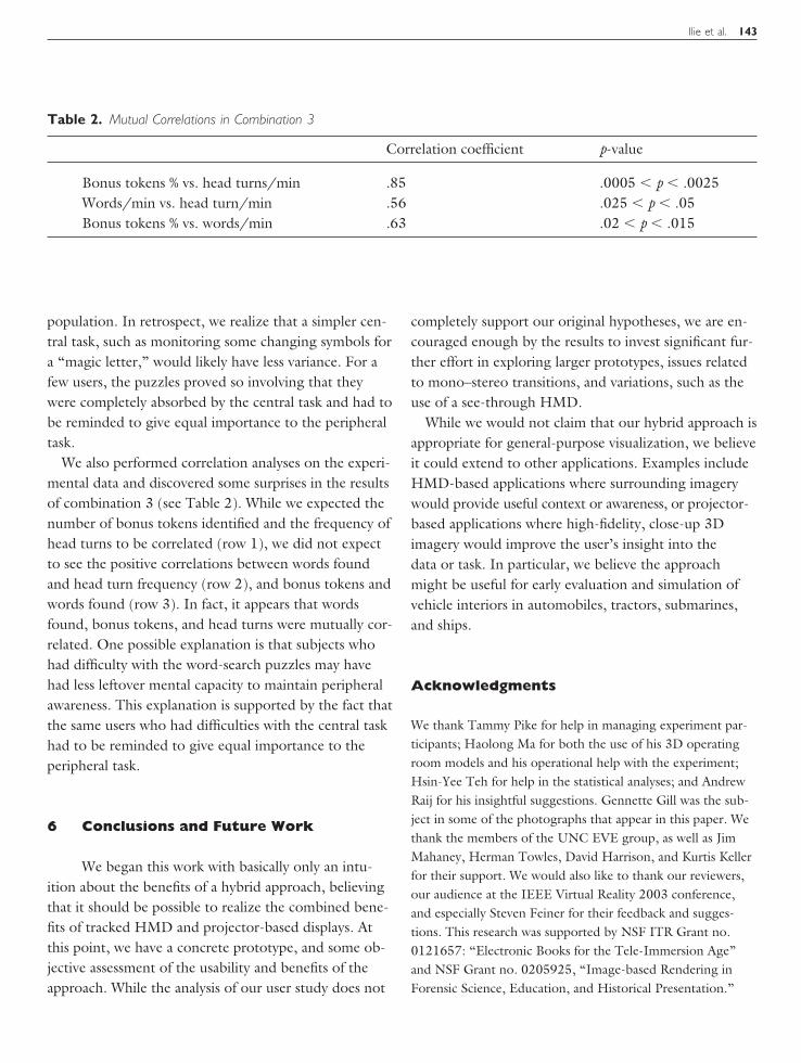