adsl system enhancement with multiuser detection liang c. chu school of electrical engineering...
TRANSCRIPT
ADSL System Enhancement ADSL System Enhancement with Multiuser Detectionwith Multiuser Detection
Liang C. ChuLiang C. Chu
School of Electrical EngineeringSchool of Electrical Engineering
Georgia Institute of TechnologyGeorgia Institute of Technology
Atlanta, GA 30332Atlanta, GA 30332

Table of ContentsTable of Contents
Introduction Background: History of the Problem.
Crosstalk ADSL and SDSL in a binder.
DMT-ADSL Channel Characteristics DMT DMT-ADSL Standard
Multiuser Transmission Telephone Channel Multiuser Transmission Systems

ADSL System Enhancement Multiuser Detection on DMT-ADSL Channel Capacity Studies Joint MLSE Performance Studies
Low Complexity Enhancement on ADSL Receiver Tone-zeroing Multi-stage JMLSE
Simulation Studies and Results Conclusions Recommendations

IntroductionIntroduction An enhancement approach on the DMT-ADSL system.
Goal: spectral compatibility; better capacity utilization; support fast Internet services.
Core method: either increasing signal constellation sizes / per sub-channel, or extending the deployment ranges with a fixed transmission rate, or compensating on a poor BER channel in achieving better throughput.
ADSL service Telephone channel, high-bandwidth services. New infrastructure for multimedia service. Economical and less time to launch service.
Physical channel medium: unshielded twisted pair line.
Co-channel interference (crosstalk). TPC model and proposed multiuser model. Sub-optimal approach on receiver
enhancement.

Background Problems Background Problems
Major threat: spectral compatibility. Signals coupling in same binder crosstalk
NEXT Near-end crosstalk
FEXT Far-end crosstalk

Crosstalk Comes FromCrosstalk Comes From
Environmental Physical media: unshielded twisted pair. Bandwidth-efficient digital transmission system. Different kinds of DSL services in same binder.

Near-End CrosstalkNear-End Crosstalk
NEXT
Same Binder Group
Transmit
Receive
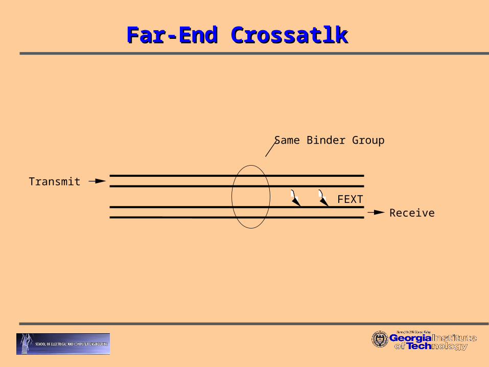
Far-End CrossatlkFar-End Crossatlk
FEXT
Same Binder Group
Transmit
Receive

Crosstalk CharacteristicsCrosstalk Characteristics
NEXT: dependent on frequency.
FEXT: dependent on frequency, but
attenuated by twisted cable length.
2/3fH nNEXT
22|)(| flkfHH channelFEXT

Example on NEXT and FEXTExample on NEXT and FEXT
Results:maximum theoretical data rate. NEXT and FEXT limited operation on ADSL.
ANSI ADSL, 256 channels from DC to 1.104MHz Tones #7 to #255 for data transmission. Each tone: QAM at 0 to 15 bits/Hz based on SNR AWGN at –140dbm/Hz, no ISI assumed
NEXT is the dominated crosstalk.

NEXT Coupling CharacteristicsNEXT Coupling Characteristics
NEXT POWER SUM LOSS(dB)
1000 FT, 24 AWG PIC
0
10
20
30
40
50
60
70
0.1 1 10 100
FREQUENCY(MHz) 1% Case

DiscussionsDiscussions
NEXT increases as f1.5 with frequency, but with significant variation in coupling function.
Any given frequency, only few other pairs may contribute significantly to crosstalk, but over all frequencies, many wire lines contribute randomly.
Challenge: hard to detect in single-user detection. Solution: modify receiver.

Current Crosstalk DistributionCurrent Crosstalk Distribution
Gaussian Distribution. Random interferes, central limit theorem.
Practical interests and only accurate on single type of
crosstalk.
Drawback: dependent on error size of Gaussian and true
distribution.
Pessimistic on channel capacity especially on multiple DSL
services.
New area on multiple DSL services crosstalk
models.

SDSL to ADSL (Multiple DSLs)SDSL to ADSL (Multiple DSLs)
SDSL: symmetric DSL 2B1Q modulation - 4-level baseband pulse amplitude
modulation signals same data rate in the upstream and downstream
directions same transmit PSD in the upstream and downstream
directions
Focus studies on SDSL crosstalk to ADSL SDSL services in high demand, together exiting with
ADSL service.

PSD of 2B1Q SDSLPSD of 2B1Q SDSL
Spectral compatibility problem with ADSL overlap in psd
1168, 1552 and 2320 kbps SDSL
-110
-100
-90
-80
-70
-60
-50
-40
-30
0 400000 800000 1200000 1600000 2000000
Frequency (Hz)
PS
D (
dB
m/H
z)
1168 kbps
1552 kbps
2320 kbps

SDSL with T1.413 ADSLSDSL with T1.413 ADSL
Results are calculated for same-binder NEXT with the standard Unger 1% NEXT model.
T1.413 full-rate DMT ADSL in the presence of NEXT from SDSL (1552 kbps and 2320 kbps). DMT tones separated by 4.3125 kHz. each tone carries with a 6dB SNR margin. Downstream ADSL transmits from 160 kHz to 1104
kHz.

SDSL Crosstalk to ADSLSDSL Crosstalk to ADSL
6 8 10 12 14 16 18
1000
2000
3000
4000
5000
6000
7000
8000
26-AWG Loop Length in kft
Dow
nst
ream
Bit
Rat
e in
kb
ps
DMT-ADSL System with 24-SDSL Crosstalk
1552 kbps SDSL crosstalk
2320 kbps SDSL Crosstalk
Simulation based on ANSI T1E1.4/99-261
SDSL self-NEXT loop limits:
1552 kbps to 7.5 kft
2320 kbps to 6 kft

Current Mitigation PlanCurrent Mitigation Plan
Loop plan Testing & estimating deployment loops. Limiting coverage area and customers. Limiting on deployed data rate.
Drawback: Inconvenience. Capacity waste.
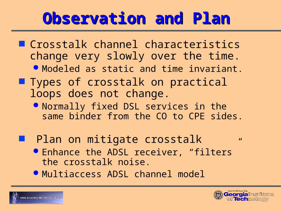
Observation and PlanObservation and Plan
Crosstalk channel characteristics change very slowly over the time. Modeled as static and time invariant.
Types of crosstalk on practical loops does not change. Normally fixed DSL services in the same binder from
the CO to CPE sides. Plan on mitigate crosstalk
Enhance the ADSL receiver, “filters” the crosstalk noise.
Multiaccess ADSL channel model

Multiaccess ADSL Channel ModelMultiaccess ADSL Channel Model
Noise, 2
+
+ ADSL ReceiverADSL Channel
Crosstalk Filtering
Crosstalk Filtering
Transmit1 (x1)
Transmit2 (x2)
Transmitk (xk)
r
x
y
)()()()(1
inixihir k
K
kk
hk is the channel impulse response when
k=1, and sum together with crosstalk coupling function when k>1

Discussions Discussions
Background noise is Gaussian. DSL: Gaussian channel
Crosstalk is not Gaussian distribution. Sum of several filtered discrete data signals:
ADSL (desired) and SDSL (crosstalk).
Channel model: multiple input and single
(vector) output.

Brief on DMTBrief on DMT
Basic Principle: Split available BW into a large number of subchannels.
Motivation: Make BW of each the sub-channel sufficiently narrow,
then no ISI occurs on any sub-channel.
Technique method: Transmits many parallel data-streams concurrently over
the transmission channel.

DMT-ADSL (ANSI)DMT-ADSL (ANSI)
Two traffic channels downstream transmission:
sampling rate of 2.208 MHz, a block size of 512 (FFT), meaning 256 tones from 0 to 1.104MHz.
symbol rate is 4 kHz and the width of a tone is 4.3125 kHz. Average downstream PSD is –40 dBm/Hz.
Upstream transmission:sampling rate of 276 kHz, a block size 64, meaning 32 tones
from 0 to 138 kHz. symbol rate is 4 kHz and the width of the tone remains 4.3125
kHz. Average upstream PSD is –38 dBm/Hz

DMT-ADSL SpectrumDMT-ADSL Spectrum
Frequency in kHz
1104240138304
Upstream Channel Downstream Channel
POTS
14
# of Bits
0

Loading AlgorithmLoading Algorithm
Bits/channel
Frequency Frequency Frequency
Crosstalk
AMAttenuation

Physical ChannelPhysical Channel
Unshielded twisted pairs does not change its physical behavior significantly with
time and considered a stationary channel. The transfer function:
The sources of noise in the telephone channel:digital quantization noise, thermal noise in detectors,
impulse noise and crosstalk.
Telephone channel is normally treated as a Gaussian channel.
dRCfatt
efdH 1010),(

Multiuser TransmissionsMultiuser Transmissions
The fundamental limit of multiuser detection: mitigate the interference among different modulated
signals.
Basic model:
(4.2.1.1)
multiuserchannel
.
.
.
x1
x2
xL
XY
NXY H
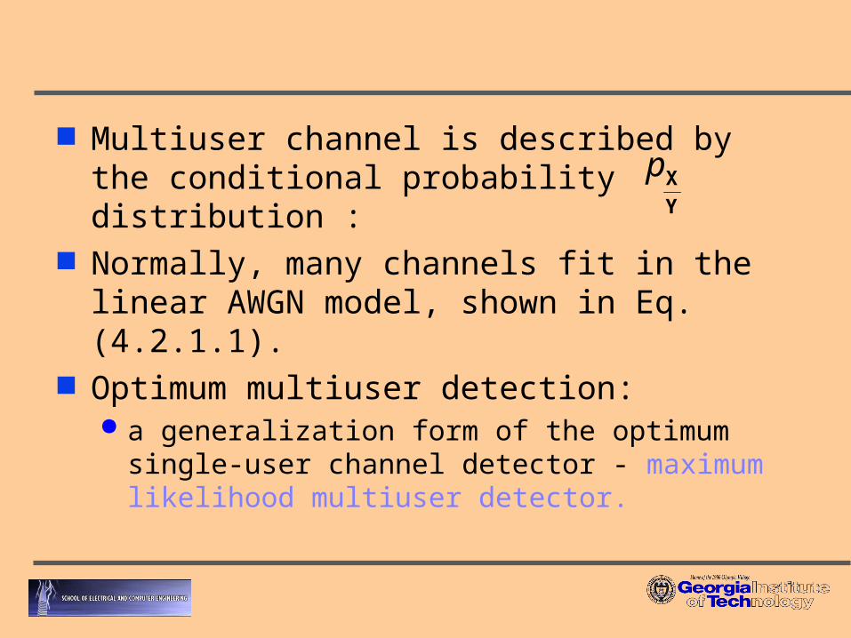
Multiuser channel is described by the conditional probability distribution :
Normally, many channels fit in the linear AWGN model, shown in Eq. (4.2.1.1).
Optimum multiuser detection: a generalization form of the optimum single-user
channel detector - maximum likelihood multiuser detector.
Y
Xp

Linear multiuser detection in AWGN channel As Eq. (4.2.1.1) detection of desired input user xl, it may be that the overall
minimum distance is too small: a single fixed value for xl may corresponding to the two multiuser
codewords that determine the overall dmin.
defined as : (4.2.2.1.1)
Results: (4.2.2.1.2)
it is possible for a detector extracting a single user to have better performance on one that extracts all other users.
)(min 'min, ''
XXXX
Hdll xx
l
minmin, dd l

Channel CapacityChannel Capacity
Conventional single-user ADSL receiver Sum all the crosstalk signals and background noise
together as AWGN.
(5.1.2.5)
Enhanced multiuser ADSL receiver JMLSE – selects all possible inputs, min. distance on
output.
(5.1.2.8)
dffPfHfN
fPfHC
erferenceNEXTo
desiredc
PP
usergle
erferencedesired
])(|)(|)(
)(|)(|1[log
int2
2
0
2sin supint,
dffN
fPfHC
o
desiredc
P
multiuser
desired
])(
)(|)(|1[log
2
0
2sup
Two UsersTwo Users
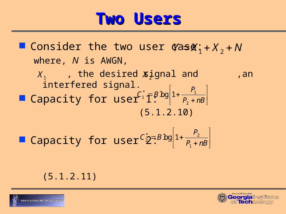
Consider the two user case:where, N is AWGN,
, the desired signal and ,an interfered signal. Capacity for user 1: (5.1.2.10)
Capacity for user 2: (5.1.2.11)
NXXY 21
1X 2X
úû
ùêë
é
nBP
PBC
2
1*1 1log
úû
ùêë
é
nBP
PBC
1
2*2 1log

Jointly detect, then the achievable capacity:
(5.1.2.12)
Considerable capacity improvement when the interference structure is taken into account.
(5.1.2.13)
úûù
êëé £
nB
PBR i
i 1log úûù
êëé
£nB
PPBRR 21
21 1log
úûù
êëé
nB
PBC i
i 1log

Single vs. Multiuser Channels
Rate(User 1)
Multiuser
SingleUser
C1
C1*
C2C2*
Rate(User 2)
Alternative ViewpointAlternative Viewpoint
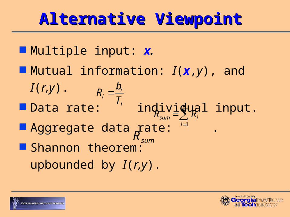
Multiple input: x.
Mutual information: I(x,y), and I(r,y).
Data rate: individual input.
Aggregate data rate: .
Shannon theorem: upbounded by
I(r,y).
i
ii T
bR
k
iisum RR
1
sumR

Achievable data rate on desired channel:
(5.1.2.15) Discussion:
Limit on (5.1.2.15) can be much larger than the data rate based on Gaussian crosstalk assumptions.
The sum on right can be much smaller number, due to frequency-selective crosstalk coupling function.
k
iidesired RyrIR
2
),(

Analysis and ExamplesAnalysis and Examples
SDSL Crosstalk
ADSL Channel
Example#1 Example#2

Example #1:crosstalk mutual informationExample #1:crosstalk mutual information
1552 kbps SDSL coupling to ADSL
Mutual information of crosstalk on each DMT-ADSL tone
.5.78),( kbpsyxI adslsdsl
If silence near 20 tones, fully detected
Unger 1% model, 5.1910 f
)101(log3125.4 52.80.142
kHz
kbpskbps 1552205.78
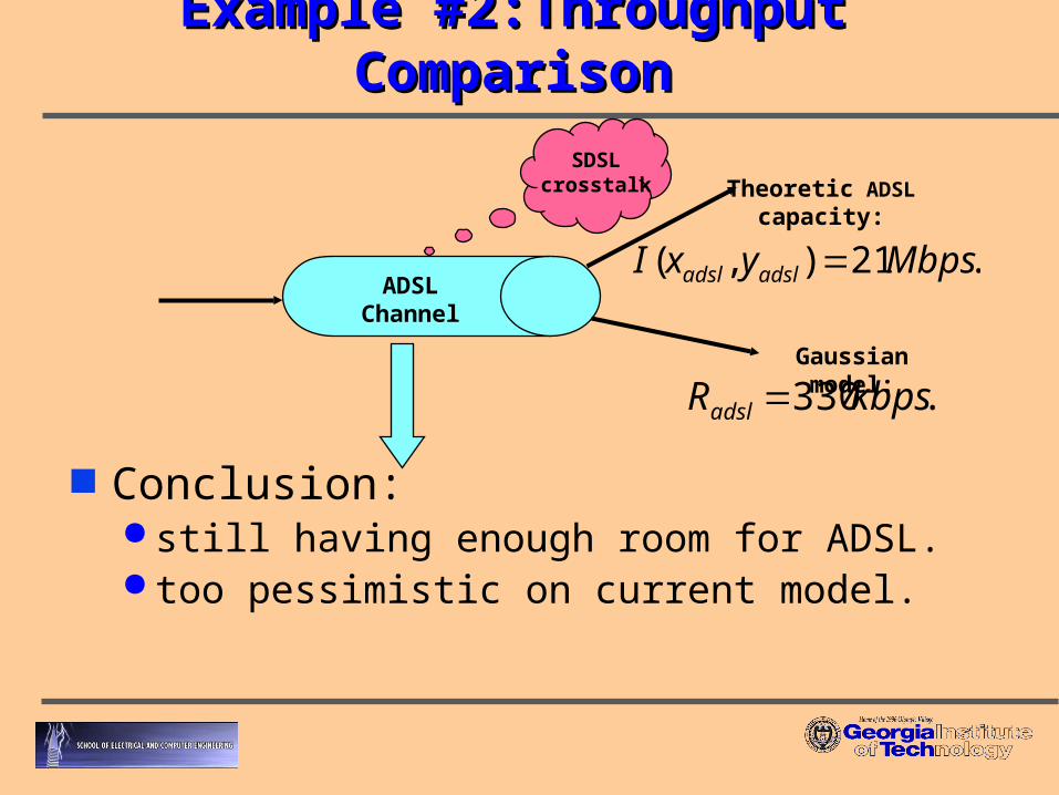
Example #2:Throughput ComparisonExample #2:Throughput Comparison
Conclusion: still having enough room for ADSL. too pessimistic on current model.
Theoretic ADSL capacity:
.21),( MbpsyxI adsladsl
SDSL crosstalk
ADSL Channel
Gaussian model:
.330kbpsRadsl

Joint MLSEJoint MLSE
Principle search all possible transmitted signals, find a
best match signal set on the received signal.
The best detector, with upper bound on
multiuser system.
Drawback: large computational complexity.

Details on ReceiverDetails on Receiver
Viterbi decoding: engine for MLSE receiver. Select the state having the smallest accumulated error
metric and save the state number of that state. Iteratively perform the following step until the
beginning of the trellis is reached: working backward through the state history table, for the selected state, select a new state, which is listed in the state history table as being the predecessor to that state. Save the state number of each selected state. This second step is called traceback.

work forward through the list of selected states saved in the previous steps. Look up what best estimated input bit corresponds to a transition from each predecessor state to its successor state.
Use T/2-spaced MLSE Receiver eliminate implementation for whitening matched filters
- with fixed analog filters, not depend on unknown channel (pulse shaping filter).
nearly insensitive to sampling time off-set, capable of recoving non synchronized cochannel signals more easily.

JMLSE ADSL Receiver (Optimal)JMLSE ADSL Receiver (Optimal)
Multiple input and single output model. Detect desired ADSL and filtered coupling crosstalk signals.
JMLSE ADSL Receiver extension of the single channel MLSE. assume Gaussian channel. Ex: co-channel pairs case:JMLSE selects the ith joint symbol
sequence { } that maximizes the metric
(5.2.6.1)
meaning: select a signal set with minimized distance from the received signals.
Method:Joint Viterbi algorithm.
ki
ki xx 2,1, ,
),|(),|( ,2,1,2,1k
jk
jkk
ik
ik xxrpxxrp

Joint Viterbi AlgorithmJoint Viterbi Algorithm
Objective: determine the pair of sequence
that minimizes the sum of squared errors
defined by the error sequence: .
},{ 2,1,kj
ki xx
kjie ,
+
rk
Primary Channel Estimate
Secondary Channel Estimate
+
kix 1,
kjir,ˆ -
kjie ,
kjx ,2
f1(k)
f2(k)

Joint VA (JVA) for JMLSE is very similar to the standard VA. Joint state: number of states required to implement JVA: Each joint state at time k-1:
Transition to states at time k.Be reached by same number of states from time k-2.
},{ 1,1,2
1,1,1
1,1 21 Lki
Lki
Lki ssS
21 LLM
2M

Prototype on Modification of ReceiverPrototype on Modification of Receiver
Noise, 2
+Transmit1 (x1)
Transmit2 (x2)
Transmitk (xk)
r
+
+ LE
JMLSD
Feedback
Section
H

Performance Study (Optimal)Performance Study (Optimal)
17 17.5 18 18.5 19 19.5 20 20.5 21 21.5 2210
-16
10-14
10-12
10-10
10-8
10-6
10-4
10-2
SNR in dB
BE
RBit Error Rate for ADSL
single-user detector
multiuser via JMLSE
one SDSL disturber NEXT into one T1.413 full rate
DMT-ADSL system
gap of 4 dB ,FIR channel with 256
memory states

4 6 8 10 12 14 16 18-30
-25
-20
-15
-10
-5
0
5
10
15
20
ADSL Service Length in kft
Mar
gin
s in
dB
JMLSD
Single-user Detector with SDSL Crosstalk

Low Complexity EnhancementLow Complexity Enhancement
JMLSE is an optimal solution. drawback: high computational complexity.
Goal: Reduce computational complexity Multistage JMLSE: multiple MLSE “like”. Tone zeroing: use DMT loading algorithm, and
“adaptive decision feedback” or “echo cancellation like”.
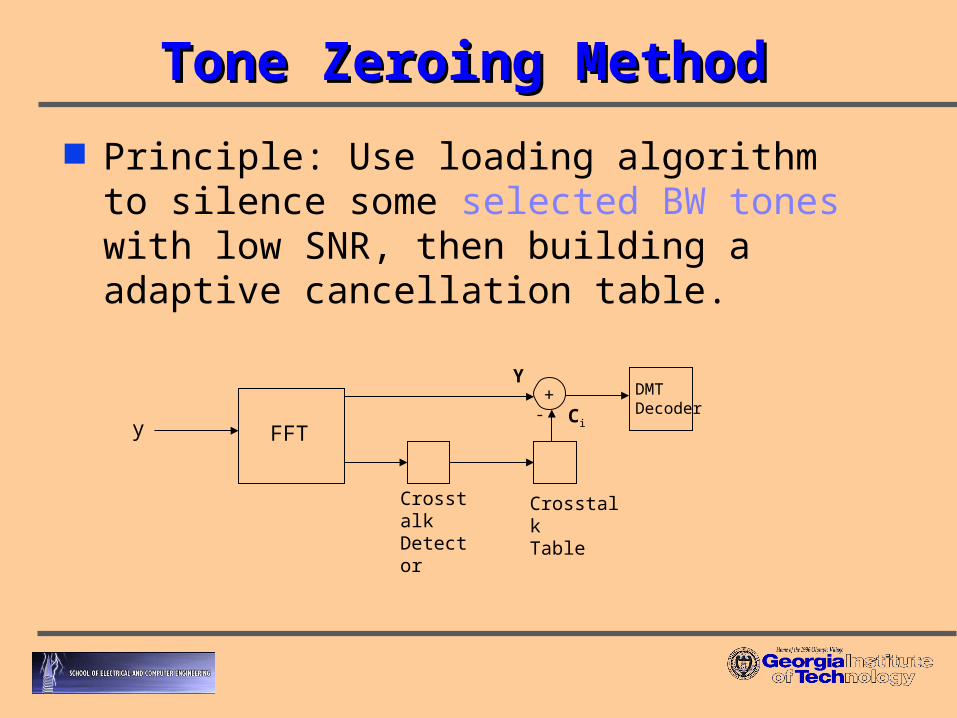
Tone Zeroing MethodTone Zeroing Method
Principle: Use loading algorithm to silence some selected BW tones with low SNR, then building a adaptive cancellation table.
y FFT
CrosstalkDetector
CrosstalkTable
+ DMTDecoder
Y
Ci-

SDSL Coupling to ADSL SDSL Coupling to ADSL ExampleExample
Adjacent pairs: SDSL to ADSL. assume ADSL channel is static. relative constant on crosstalk profile table using LMS
algorithm. zeroing about 20 tones to build up a NEXT cancellation
table. Result: up to 6 dB in margin. Discussions:
advantage of mitigate the NEXT and complexity reduction (comparing with JMLSE) with asymmetric and symmetric services coexist.

key issue for the tone zeroing is necessity of accurate modeling of noise (crosstalk).
feedback section is using some kind of adaptive filter technique, and adaptive filter coefficient is largely depends on frequency components with high power.
If a frequency band making NEXT noise has small power, it can not be modeled correctly due to high power frequency component until sufficient number of coefficient are used.
tone zeroing modeling works well for high frequency power noise component.

telephone channel, many kinds of random noises often occur in any selected frequency band.
may make an error decision on the cancellation table and induce error propagation.
Proposed multi-stage joint MLSE for ADSL receiver (applied to both DMT and non-DMT DSL solutions).

Same Example w/Tone-ZeroingSame Example w/Tone-Zeroing
4 6 8 10 12 14 16 18-30
-25
-20
-15
-10
-5
0
5
10
15
20
ADSL Service Length in kft
Mar
gins
in d
B
JMLSE
Single-user Detector with SDSL Crosstalk
Tone-zeroing

Complexity Reduced JMLSEComplexity Reduced JMLSE
Multi-stage JVA very similar to conventional VA receiver. having multi-stage inputs and outputs. Method as adjacent pair-wise case:
the primary (strong) signal r1(k) is estimated using low delay decisions from a single-channel VA, and is forwarded to the second VA section to estimate the co-channel signal.
Advantage: this structure is largely reducing the complexity on optimal JVA (JMLSE). Complexity as a similar range of a conventional VA,
with just a scale-increasing factor by N.
)(ˆ)( 1 krkr

NN Co-channel Binder Co-channel Binder
Ratio:
Assume equal lengths, L,
obvious to us R is always (much) < 1.
N
N
LLL
LLL
M
MMMR
...21
21 ...
JMLSE
Multi-stage JMLSE
)1( NLLN
L
MNM
MNR

Two Methods (Pair-wise)Two Methods (Pair-wise)
VA 1LM states
VA 2LM states +
+
_
1L
r(k)
)(ˆ11 Lkd )(ˆ
22 Lkd
)(ˆ1 kd
)(ˆ)( 11 krkr
VA 1LM states
VA 2LM states
+ + +
_
)(ˆ2 kf
)1(1̂ kf
+
_ r(k)
)(ˆ11 Lkd )(ˆ
22 Lkd
)(ˆ 2,2 kd Lk
)(ˆ 1,1 kd Lk
)1(2̂ kr
)(1 ks )(2 ks
)(1̂ kr
Two-stage JVA ,without Feedback Section
Two-stage JVA ,with Feedback Section
only an additional L tap filter computational
increasing
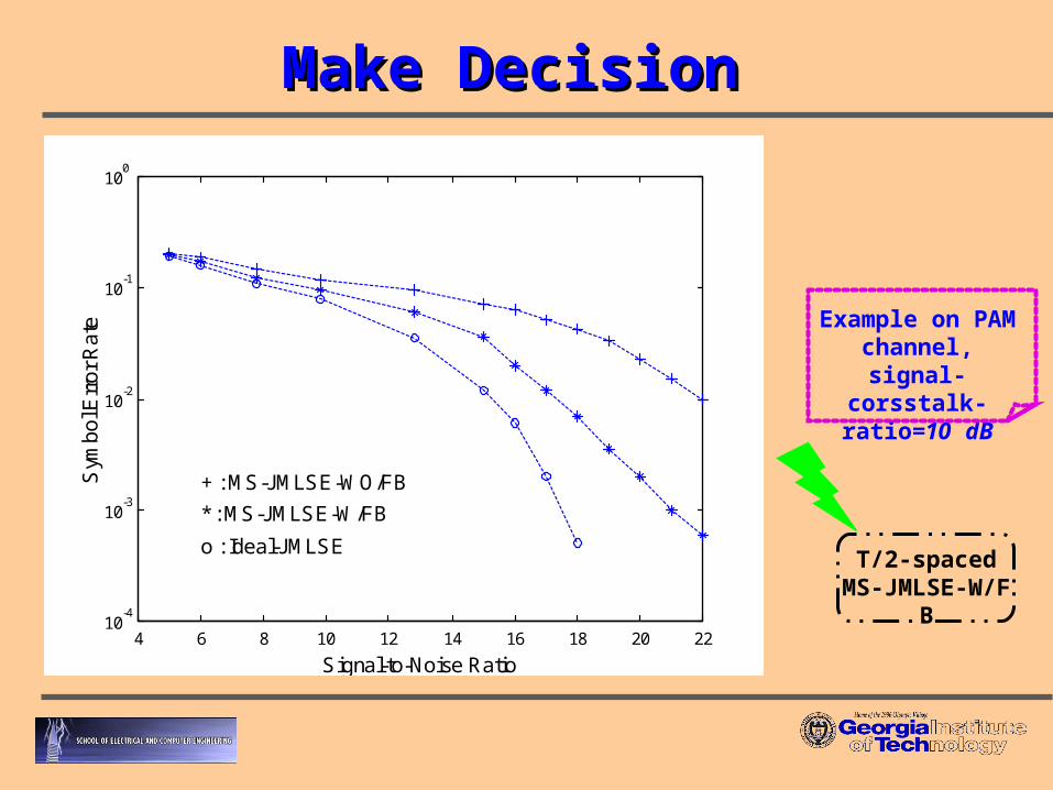
Make DecisionMake Decision
4 6 8 10 12 14 16 18 20 2210
-4
10-3
10-2
10-1
100
Signal-to-Noise Ratio
Sym
bo
l Err
or
Ra
te
* : MS-JMLSE-W/FB
o : Ideal-JMLSE
+ : MS-JMLSE-WO/FB
Example on PAM channel, signal-
corsstalk-ratio=10 dB
T/2-spaced MS-JMLSE-W/FB

Performance SimulationsPerformance Simulations
Test Environment SDSL and other DSLs NEXT to ADSL.
Loop Characteristics
ATU - RATU - C
ATU - RATU - C
ATU - RATU - C
18000 ft
26 AWG
6000 ft
26 AWG
1500 ft
26 AWG
3000 ft
26 AWG
9000 ft
26 AWG
2000 ft
24 AWG
500 ft
24 AWG
500 ft
24 AWG
1500 ft26 AWG
1500 ft26 AWG
1500 ft26 AWG
1500 ft26 AWG
1500 ft26 AWG
Test Loop #3
Test Loop #1
Test Loop#2
ATU - RATU-C
ATU - RATU- C
ATU - RATU-C
26 AWG
6000 ft
26 AWG
1500 ft
26 AWG
3000 ft
9000 ft
26 AWG
2000 ft
24 AWG
500 ft
24 AWG
500 ft
24 AWG
1500 ft 1500 ft26 AWG
1500 ft26 AWG
1500 ft26 AWG
1500 ft26 AWG

Test Loop #1Test Loop #1
9 10 11 12 13 14 15 16 17 180
0.5
1
1.5
2
2.5
3
3.5
4
ADSL Service Length in kft
Ach
ieva
ble
Do
wns
tre
am
Da
ta R
ate
in M
bp
s square : ideal JMLSE
x : multi-stage JMLSE
o : conventional ADSL receiver

Test Loop #2Test Loop #2
9 10 11 12 13 14 15 16 17 180
0.5
1
1.5
2
2.5
3
3.5
ADSL Service Length in kft
Ach
ieva
ble
Do
wns
tre
am
Da
ta R
ate
in M
bp
s
square : ideal JMLSE
x : multi-stage JMLSE
o : conventional ADSL receiver

Test Loop #3Test Loop #3
4 6 8 10 12 14 16 18 200
1
2
3
4
5
6
7
8
9
10
ADSL Service Length in kft
Ach
ieva
ble
Do
wns
tre
am
Da
ta R
ate
in M
bp
s
square : ideal JMLSE
x : multi-stage JMLSE
o : conventional ADSL receiver
extensionprediction
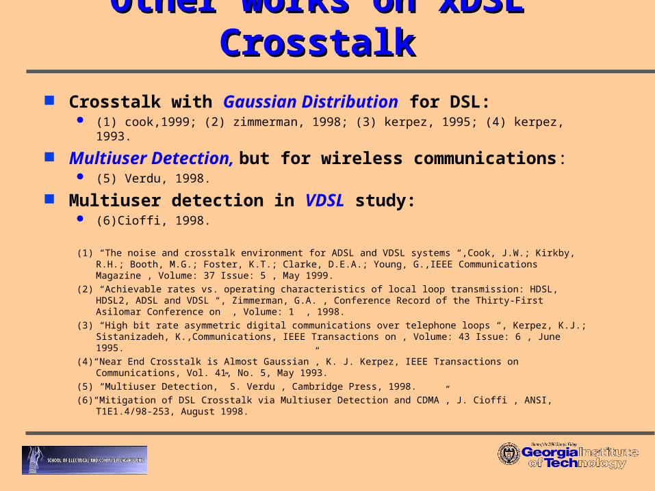
Other works on xDSL CrosstalkOther works on xDSL Crosstalk Crosstalk with Gaussian Distribution for DSL:
(1) cook,1999; (2) zimmerman, 1998; (3) kerpez, 1995; (4) kerpez, 1993.
Multiuser Detection, but for wireless communications: (5) Verdu, 1998.
Multiuser detection in VDSL study: (6)Cioffi, 1998.
(1) “The noise and crosstalk environment for ADSL and VDSL systems “,Cook, J.W.; Kirkby, R.H.; Booth, M.G.; Foster, K.T.; Clarke, D.E.A.; Young, G.,IEEE Communications Magazine , Volume: 37 Issue: 5 , May 1999.
(2) “Achievable rates vs. operating characteristics of local loop transmission: HDSL, HDSL2, ADSL and VDSL “, Zimmerman, G.A. , Conference Record of the Thirty-First Asilomar Conference on , Volume: 1 , 1998.
(3) “High bit rate asymmetric digital communications over telephone loops “, Kerpez, K.J.; Sistanizadeh, K.,Communications, IEEE Transactions on , Volume: 43 Issue: 6 , June 1995.
(4)“Near End Crosstalk is Almost Gaussian”, K. J. Kerpez, IEEE Transactions on Communications, Vol. 41, No. 5, May 1993.
(5) “Multiuser Detection,” S. Verdu , Cambridge Press, 1998.
(6)“Mitigation of DSL Crosstalk via Multiuser Detection and CDMA”, J. Cioffi , ANSI, T1E1.4/98-253, August 1998.

Related DSL PublicationsRelated DSL Publications
“An Enhancement Study on the SDSL Upstream Receiver”, 2001 IEEE International Symposium on , Volume: 4 , 6-9 May 2001, Page(s): 442 –445.
“Mitigation of Crosstalk on the SDSL Upstream Transmission with Vector Equalization”, IEEE International Conference on Communications, Session AN5: Transmission Systems, Helsinki, Finland, June 11-14, 2001 .
“A Study on Multiuser DSL Channel Capacity with Crosstalk Environment”, 2001 IEEE Pacific Rim Conference on Communications, Computers, and Signal Processing, Session MP4: DSP for Communications, Victoria, BC, Canada, August 24-28, 2001.
“Performance Enhancement on a Multiuser Detection ADSL Modem”, In preparation to IEEE Transitions on Consumer Electronics.
“Complexity Reduced ADSL System with Multiuser Detection ”, Submitted to 2002 IEEE International Conference on Communications.

ConclusionsConclusions
Overview the problem on xDSL spectral compatibility problems.
Traditional Gaussian crosstalk under-project ADSL achievable capacity.
ADSL system enhancement with multiuser detection. a core method on improvements of either increasing transmission
data rate, or extending deployment areas, or compensating in poor BER DSL channels, based on different requirements.
Enhanced ADSL receiver has acceptable computational complexity for a chip realization.
Benefit on QoS for last-mile fats Internet transmission.

RecommendationsRecommendations
This approach can apply to DMT and non-DMT ADSL, HDSL, SDSL and future VDSL studies. may extensible to fiber and wireless.
Other complexity reduction methods for JVA decoding can be further studied (this thesis gives a kind of beginning point).
Possible dual-mode DSL transceivers.