advance continuous casting of ag-cu alloy · and roll casting process as a new fabrication method...
TRANSCRIPT
1
Page 1 of 29
Advance Continuous Casting
Of Ag-Cu Alloy
2
Page 2 of 29
DECLARATION
I the M Tech students of Materials & Systems Engineering Design from NIT Warangal
hereby declare that the entire work embodied in this Laboratory “ADVANCE CONTINUOUS
CASTING OF Ag-Cu ALLOY” has been carried out by me.
No part of it has been submitted for the award of any Degree or Diploma at any other
University or Institution.
Vaibhav A. Chilate [143752]

3
Page 3 of 29
S.No CONTENTS Page no
1 List of figures 5
2 Abstract 6
3 Aim and Objective 7
4 Introduction to the continuous castig process 8
5 Background theory 9
6 Process and equipment design 10
7 1.1 Induction furnace 11
8 1.2 Insulation parts 13
9 1.3 Graphite crucible 14
10 1.4 Plug rod 15
11 1.5 Temperature sensor 15
12 2.1 Die and water assembly 18
13 2.2 Solid-Liquid interphase 18
14 3.1 Roller and rolling mechanism 19
15 4.1 Control panel function 19
16 Experimental details 21

4
Page 4 of 29
17 Calculations 22
18 Microstructure of Ag-Cu 24
19 Thermal Images 24
20 Tesile Test of Ag-Cu alloy 25
21 Conclusion 29
5
Page 5 of 29
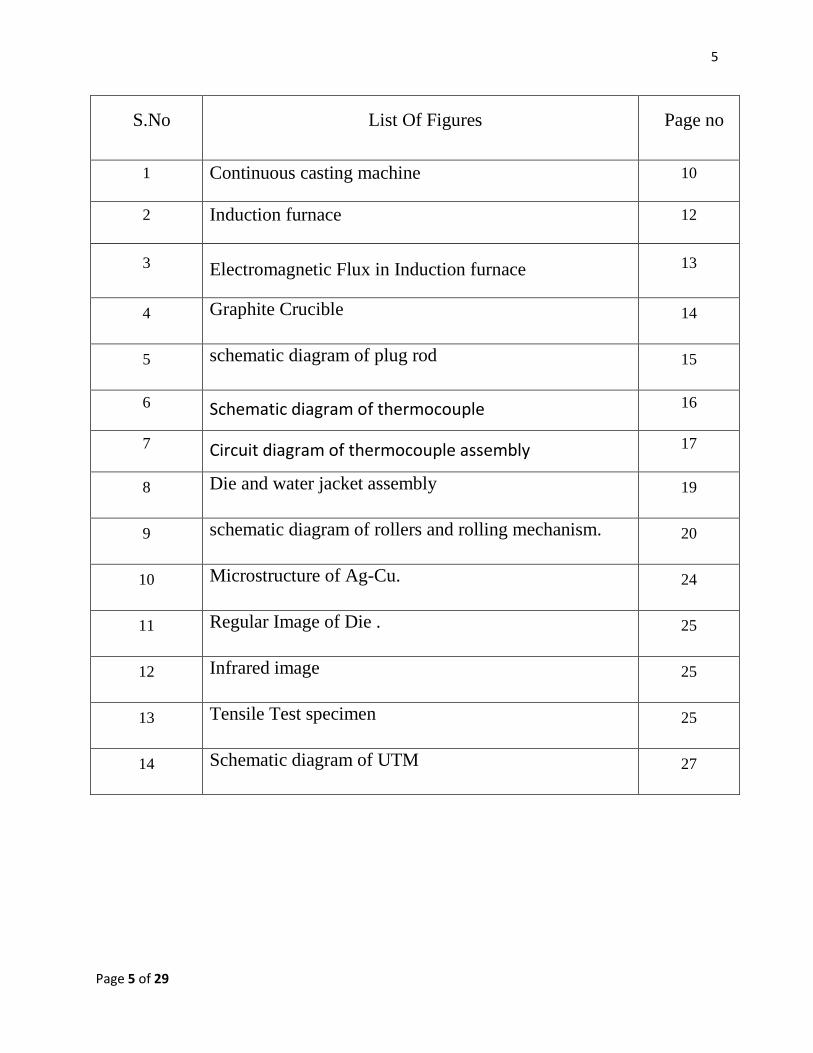
S.No List Of Figures Page no
1 Continuous casting machine 10
2 Induction furnace 12
3 Electromagnetic Flux in Induction furnace 13
4 Graphite Crucible 14
5 schematic diagram of plug rod 15
6 Schematic diagram of thermocouple 16
7 Circuit diagram of thermocouple assembly 17
8 Die and water jacket assembly 19
9 schematic diagram of rollers and rolling mechanism. 20
10 Microstructure of Ag-Cu. 24
11 Regular Image of Die . 25
12 Infrared image 25
13 Tensile Test specimen 25
14 Schematic diagram of UTM 27

6
Page 6 of 29
ABSTRACT:
This study sought to examine the suitability of the Advance Continuous strip
and roll casting process as a new fabrication method for Ag-Cu brazing alloy. In
this, all the stages of casting performed on single machine itself as a automated
controlled system. Indeed, it is more effective and efficient casting method for
continuous product such as planner strip casting, melt dragging, roll strip casting.
In this particularly, the final product gets without any loss of materials, and it
would be almost defect free. Such casting product uses for precise purpose like
brazing in aircraft, missiles, rocket, and supersonic jet etc. In particular,
continuous strip casting was found to realize the best strip shaping ability and
microstrutural homogeneity. The effect on mechanical properties of Ag-Cu strip
was also investigated through tensile test, vicker hardness test, optical
microscopic, And scanning electronic microscopic(SEM) observations.

7
Page 7 of 29
Aim and Objectives:
The objective of this technology is to understand the design, operating principle
and mechanical properties of continuous casting machine as a system.

8
Page 8 of 29
Introduction to the continuous casting process:
Continuous casting is a process that molten melt is solidified into a semi-
finished bloom, billet or slab. The molten metal solidifies against the mold walls
while it is simultaneously withdrawn from the bottom of the mold at a rate which
maintains the solid / liquid interface at a constant position with time. The process
works best when all of its aspects operate in this steady-state manner.
In this, inductive furnace is used for melting the raw materials ( pure silver
and 99.99% pure copper ) where melting temperature is reached rapidly, because
the heat is directly generated in the metal and in the crucible. As the metal is
poured through the crucible bottom, only pure metal can reach into the die,
whereas contamination stays on the surface and can cover the top of the cast.
Benefits of continuous casting process are:
1) higher yield,
2) semi finished products,
3) less segregation,
4) better surface finish.
Apparatus Required:
Followings are the main apparatus required during operation of continuous
casting process.
Continuous casting machine setup.
Power supply through mains.
Graphite crucible and die.
Thermocouples.
Ceramic wool insulator.
Ejector rod.
9
Page 9 of 29
Background Theory:
According to a report from American Iron and Steel Institute in 2005 , it
is estimated that a 1% reduction of scrapped product due to casting related defects
(such as slab cracking from improper cooling, porosity, etc.) can result in an
annual energy saving of 0.147 trillion kJ for a single steel plant in their region of
the United State .In continuous casting process it is possible to control on such
defects ( porosity, macrosegregation ) thus, increase in tremendous saving energy
would be beneficial. Therefore, to predict porosity and macrosegregation defects in
the continuous casting process more sophisticated models are needed.
10
Page 10 of 29
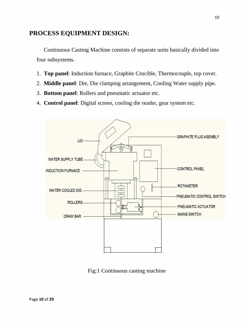
PROCESS EQUIPMENT DESIGN:
Continuous Casting Machine consists of separate units basically divided into
four subsystems.
1. Top panel: Induction furnace, Graphite Crucible, Thermocouple, top cover.
2. Middle panel: Die, Die clamping arrangement, Cooling Water supply pipe.
3. Bottom panel: Rollers and pneumatic actuator etc.
4. Control panel: Digital screen, cooling die reader, gear system etc.
Fig:1 Continuous casting machine

11
Page 11 of 29
Table No. 1 Machine Details
1.1]Induction furnace: An induction furnace is an electrical furnace in
which the heat is applied by induction heating of metal. The advantage of
the induction furnace is a clean, energy-efficient and well-controllable
melting process compared to most other means of metal melting.
Sr.
No.
Parameter Details
1 Crucible Material Graphite
2 Crucible Volume 1500 cm3
3 Dimensions
Wire
Sheet
Tube
2 x Φ 15mm
100mm x 10mm
Max. Φ40mm
4 Melting Performance
Max. Power input
Mains supply
25 kW
3 phase, 400 v, 35 A,
50/60 Hz
5 Cooling Water supply 2.5 – 5 Bar, atleast 400
LPH
7 Room temperature 10 – 350 c
8 Relative Humidity 20 – 80 %
9 Compressed air Supply 6 – 8 Bar
10 Weight Approx. 250 kg

12
Page 12 of 29
Since no arc or combustion is used, the temperature of the material is no
higher than required to melt it; this can prevent loss of valuable alloying
elements. The one major drawback to induction furnace usage in a foundry
is the lack of refining capacity; charge materials must be clean of oxidation
products and of a known composition and some alloying elements may be
lost due to oxidation.
Fig:2 Induction furnace.

13
Page 13 of 29
Working Principle of induction furnace:
The principle of induction heating is mainly based on two well-known physical
phenomena:
Electromagnetic induction
ELECTROMAGNETIC INDUCTION :
The energy transfer to the object to be heated occurs by means of
electromagnetic induction. Any electrically conductive material placed in a
variable magnetic field is the site of induced electric currents, called eddy
currents, which will eventually lead to joule heating.
Fig:3 Electromagnetic Flux in Induction furnace
1.2] Insulation Parts:
In induction furnace, a ceramic insulator is provided between water cooled
copper coil and graphite crucible. Ceramic wool insulator provides protection to
the induction coil from high temperature of charge. There are different types of
insulators available such as glass wool, silica wool, ceramic wool etc.

14
Page 14 of 29
1.3] Graphite Crucible:
A crucible is a container that can withstand very high temperatures and is used
for metal, glass, and pigment production as well as a number of modern laboratory
processes. While crucibles historically were usually made from clay, they can be
made from any material that withstands temperatures high enough to melt.
Fig:4 Graphite Crucible
It is the inner part of induction furnace. It is made up of graphite because
graphite has very less coefficient of thermal expansion of the order of 3x10⁻⁶
m/mk. So it gives very good thermal stability and dimensional accuracy.

15
Page 15 of 29
1.4] Plug Rod:
Plug rod controls the flow of molten metal to the die. During the melting
process this plug rod is used to keep the die inlet closed. After the uniform
temperature is achieved in the crucible of the molten metal this is lifted up with
help of a switch provided outside. This is operated by lever mechanism.
Fig:5 schematic diagram of plug rod
1.5] TEMPERATURE SENSOR:
Thermocouple:
A thermocouple is a temperature-measuring device consisting of two
dissimilar conductors that contact each other at one or more spots.
An induction furnace for melting metal has a built-in thermocouple
assembly for continuously measuring the temperature of the molten metal.
A power controller then adjusts the power to the furnace to maintain a
predetermined temperature.

16
Page 16 of 29
The thermocouple assembly includes a refractory substrate which forms a
portion of the furnace lining partially coated with thin strips of two
thermoelectric materials so as to form a thermocouple junction.
Working Principle:
When any conductor is subjected to a thermal gradient, it will
generate a voltage. This is now known as the thermoelectric effect or
Seebeck effect.
Fig:6 Schematic diagram of thermocouple
A K – type thermocouple is used to measure the furnace, molten
metal temperature, cooling water temperatures time to time.
Properties of K type thermocouple:
Table No. 2 Properties of Thermocouple
Sr.
No.
Property Range
1 Composition:
Chromel
Alumel
90% nickel and 10%
chromium
95% nickel, 2%
17
Page 17 of 29
manganese, 2% aluminium
and 1% silicon
2 Sensitivity 41 µV/°C
3 Temperature range −200 °C to +1350 °C
4 Wire color standard Yellow (+) and Red (-).
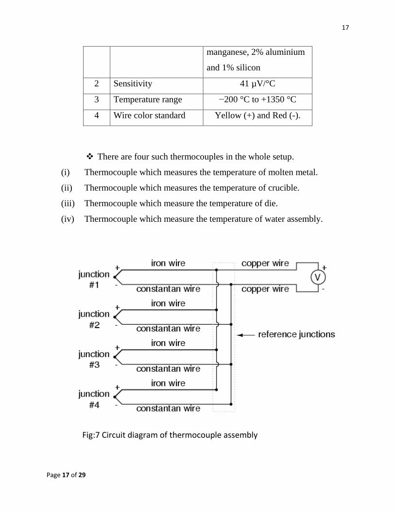
There are four such thermocouples in the whole setup.
(i) Thermocouple which measures the temperature of molten metal.
(ii) Thermocouple which measures the temperature of crucible.
(iii) Thermocouple which measure the temperature of die.
(iv) Thermocouple which measure the temperature of water assembly.
Fig:7 Circuit diagram of thermocouple assembly

18
Page 18 of 29
2.1] Die and Water jacket assembly:
Die is fixed in bottom of crucible and inserted through the furnace
in die chamber. Die chamber consists of a cooling water circulatory system that
maintain the die temperature. Die is designed according to output casting. Die has
holed (rectangular or Circular) throughout its length through which desired casting
product such as billet, bloom or slab draw out by the help of puller rod. Die is
made up of brass, cast alloy, cast steel etc. Cooling water is circulated outside the
die chamber to maintain the temperature of die at 75 oC.
Fig:8 Die and water jacket assembly
2.2] SOLID- LIQUID INTERPHASE IN DIE:
solid – liquid interface between the metal is formed in the die. This
interface plays a crucial load while selecting draw rate. If draw rate is high, the
interface is get shifted to lower level, creating threat of splashing the molten metal.
If draw rate is low, the interface can enter crucible making die cavity blocked due
to solidification.

19
Page 19 of 29
3.1] ROLLER AND ROLLING MECHANISM:
To draw the cast properly from the bottom, there is one special arrangement.
This is called as puller mechanism. On the bottom portion of machine rollers are
provided to draw the casting product and enhance the mechanical properties. Puller
rod is fixed between the rollers. There are two parallel heavy rollers are provided
to the left side of plug rod. These rollers are operated by single motor with helical
gear mechanism. On the right side of puller rod, generally three small rollers are
provided which are used to press and fixed the rod by pneumatic pressure.
Fig:9 schematic diagram of rollers and rolling mechanism.
4.1] Control Panel Functions:
Crucible Temperature –This temperature can be adjusted with the help of the
buttons “+” or “-”. This buttons could be pressed at least 5 seconds, to change the
values to the set point values. The set point values can be altered with the help of
“+” or “-” buttons.

20
Page 20 of 29
Die Temperature –
Similarly, Die cooling temperature can also be set with the help of following
buttons. We have to press the “+” or “-” buttons for at least 5 sec. an active set
point value can be adjusted with the help of red decimal point.
Power (Start/ Stop) –
These buttons are provided to turn on / turn off the generator. After turning the
generator on, we can keep the temperature adjusted to the set point value.
Water –
Water pressure is needed to be kept at appropriate levels (2 bars). Then the signal
lamp illuminates. If water pressure falls at very low values, the error signal comes.
Air –
Signal lamp illuminates when entry pressure of the compressed air is more than 4
bar. If air pressure is too low, the signal extinguishes and generator is stopped.
Draw length –
Set point level of the drawing length is indicated in this field.
Drawing Mode –
Manual Mode: As long as button is pressed, material is drawn.
Auto Mode: automatic drawing cycle is operated with this button.
Time – Set point for pausing is indicated in this field.

21
Page 21 of 29
EXPERIMENTAL DETAILS
Aim: To find the length of the casting product.
Material: Ag-Cu alloy
Composition: Copper-99.99% , Silver-99.99%
Procedure:
1) Take 72% Ag and 28% Cu by weight i.e. 2.992 kg Ag & 1.64 kg Cu, Total wt. is
4.56 kg
2) Cut this metal into small pieces on shearing machine.
3) Clean these metal pieces with acetone.
4) Dry metal pieces as well as graphite crucible by air pressure.
5) Take all these clean pieces into induction furnace.
6) Seal it with glass wool insulation.
7) Attach a metal bar for dragging purpose at the bottom of die, coated with Sic
powder.
8) Tighten the stainless steel plate and set thermocouple and closed the bell.
9) Turn on cooling water and compressed air supplies, push the main switch.
10) Supply power, and set the furnace temperature at 1085 deg ( M.P of Cu is 1083
deg & Ag-962 deg) .
11) Also Set water flow meter (die cooling) to approx. 75 deg.
12) Alloy to heat the furnace gradually in three or four stages upto its capacity
(25 Kw).
13) After getting steady state, set the temperature of induction furnace to get down to
900 deg due to lowering of M.P of alloy.
14) On pressing auto draw, alloy gets solidified and comes out in desire shape of strip
with constant speed of 1 mm/sec.

22
Page 22 of 29
15) Push drawing bar up t the mark and press. Start drawing process and check if the
drawing bar moves, than immediately open the sealing rod. This should be done
rather quickly so that the drawing bar will not be exposed to the heat more than
necessary.
16) In calculated time, entire molten metal gets solidified into strip without any
losses.
17) After getting final product, make sure that power should be off.
Safety Precautions:
1. In order to produce wire, sheet or tube of various dimensions, only die, drawing
rollers and drawing bar have to be exchanged.
2. Before casting, check if crucible, sealing rod, die and insulations etc. are clean and
undamaged.
3. Put sand on bottom to protect the fallen metal injury.
Calculations:
Table 3:
Sample Weight(kg) Density(gm/cc) Melting
Point(oC)
Silver 2.992 11.01 962 oC
Copper 1.64 8.9 1083 oC

23
Page 23 of 29
Table 4:
Time(min) Crucible
temperature(oC)
Die
temperature(oC) Power(kW)
0 146 69 9
5 230 68 9
10 422 74 15
15 627 72 15
20 990 73 25
25 1100 74 25
30 1138 75 20
35 1145 75 17
Metal Proportioning:
As we need 72 % silver and 28 % copper,
Silver available for casting = 2.992 kg
Amount of Copper required = 2.992×0.28
0.72 = 1.64 kg
Total weight of cast = 2.992+1.64 = 4.632kg
Length Calculations:
Estimated Length:
Cross section area of Die = 50mm x 5mm
Density of CuSil = 10g/cc
Length = 4.632
.5×.5×.10 = 185.28 cm

24
Page 24 of 29
Actual length of cast:
As per observation, the length of the cast has been found out to be 184.7 cm.
Hardness Value of Cusil = 232VHN
Weight of the casting = 4.56 kg.
Microstructure:
5X:
Fig: 10 Microstructure of Ag-Cu.
Thermal Imaging Photographs (IR) :
Here, with these pictures, it is demonstrated that how the gradual change in die
temperature can be measured with the help of IR Imaging Technique. It is a non –
contact type sensing technique. Although thermocouples and sensors can be used
to measure the required temperatures, but after certain range of the temperature, the
material loses its thermal stability.
Thus IR imaging technique comes of help to measure the temperatures without
having contact with the body.

25
Page 25 of 29
Fig11: Regular Image of Die . Fig:12 Infrared image
TENSILE TESTING
Aim:
To determine strength and ductility parameters of the given material by tensile
testing and comparing the properties before and after thermo mechanical processes.
Specimen Details:
Fig:13Tensile test specimen

26
Page 26 of 29
Table No. Specimen Details
Sr.
No.
Parameter Details
1 Total Length 80mm
2 Gauge Length 35 mm
3 Gauge Diameter 7.46mm
4 Temperature Set point 300c
1.4 Universal Testing Machine Details:
Table No. 8 Machine Details
Sr.
No.
Parameter Test
Value
Maximum
Value
1 Cross Head
Speed
20mm /
min
500
mm/min
2 Temperature 6000c 11000c
3 Capacity -- 25 Ton
CONSTRUCTIONAL FEATURES OF THE UNIVERSAL TESTING
MACHINE:
Universal Testing Machine consists of two pillared frame in which there is a cross
head. Crosshead can move in vertical direction up and down with the help of
hydraulic force. The specimen can be held in a column with the help of knurl
heads.

27
Page 27 of 29
Fig:14 Universal testing machine
Test Procedure:
1. The specimen is held fixed between two head jaws.
2. The load is given and specimen necking at ultimate tensile load and finally
leads to failure.
3. Simultaneously the loading and elongation is recorded as the Universal
Testing Machine is interfaced with computer. It takes the data and simulates
the stress – strain curve. The strength and ductility parameters are readily
displayed with the help of software.
28
Page 28 of 29
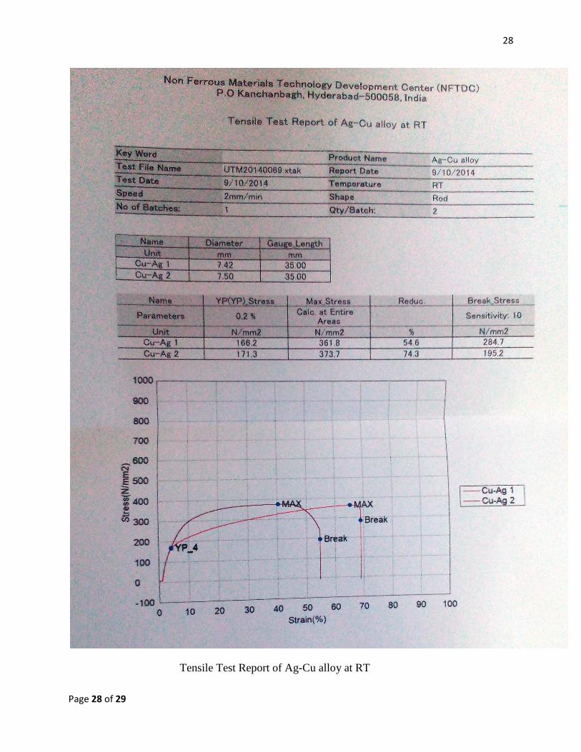
Tensile Test Report of Ag-Cu alloy at RT

29
Page 29 of 29
Results:
Material: Ag-Cu alloy
Table No. 9 Results for the Tensile Testing
Sr.
No.
Parameter Value
1 Ultimate Tensile Strength 367.75 MPa
2 Yield Stress 168.75 MPa
3 Fracture stress 239.95 Mpa
4 Percent Reduction in area 64.45%
5 Young’s Modulus 9.772 GPa
Conclusions:
higher yield.
semi finished products.
less segregation.
better surface finish.
Clean process as no metal spillage and sticking.
Near – net shape can be achieved with this process.
Less production time as casting process is continuous.