advance optima module caldos 17 - abb ltd · page chapter 1: description of functions 1-1 chapter...
TRANSCRIPT

Advance OptimaModule Caldos 17
Service Manual 43/24-1004-0 EN
SHB_C17 Contents
Table of contents
PageChapter 1: Description of functions 1-1
Chapter 2: Module variants and components 2-1
Chapter 3: Analyzer variants and assemblies 3-1
Chapter 4: Troubleshooting 4-1
Chapter 5: Testing 5-1
Chapter 6: Component replacement 6-1
Chapter 7: Configuration 7-1
Chapter 8: Calibration 8-1
Chapter 9: Parts Catalog 9-1
Contents SHB_C17
Table of contents
Chapter 1: Description of functions Page
Physical principles 1-2
Determination of influence values 1-3
Ex Concept (being prepared) 1-5
Chapter 2: Module variants and components
Rack-mount module 2-2
Wall-mount module, direct connection 2-3
Wall-mount module, hose connection 2-4
Ex-d module (being prepared) 2-5
Sensor-CPU board 2-6
Flame barriers 2-11
Chapter 3: Analyzer variants and assemblies
Analyzer, complete 3-2
Components 3-3
Chapter 4: Troubleshooting
Status Messages 4-2
Set temperature not reached 4-3
No measurement signal 4-4
Measurement signal unstable/not plausible 4-5
No flow rate 4-6
Continued on next page

SHB_C17 Contents
Table of contents, Continued
Chapter 5: Testing Page
Seal integrity 5-2
Flow rate 5-3
Measurement signal 5-4
Thermal conductivity resistors 5-6
Thermostat temperature 5-7
Temperature sensor 5-9
Heating elements 5-11
Chapter 6: Component replacement
Complete module replacement 6-2
Analyzer replacement 6-3
Thermal conductivity sensor replacement 6-5
Thermal link replacement 6-7
Preamplifier board replacement 6-8
Sensor-CPU board replacement 6-10
Flame barrier replacement (being prepared) 6-11
Chapter 7: Configuration
General 7-2
Caldos 17-Detector 7-3
Temperature Detector 7-6
Pressure Detector 7-7
Flow-Detector 7-8
Chapter 8: Calibration
Caldos 17-Detector Initial Calibration 8-2
Pressure Detector Initial Calibratin 8-4
Flow-detector Initial Calibration 8-5
Temperature Detektor Initial Calibration 8-6
Chapter 9: Parts Catalog 9-1

SHB_C_17 Chapter 1: Description of functions 1-1
Chapter 1: Description of functions
Overview
Introduction This chapter describes the underlying physical principles and the function of themodule components.
Chapter contents In this chapter you will find the following information:
Subject See page
Physical principles 1-2
Determination of influence values 1-3
Ex-d Concept (being prepared) 1-4

1-2 Chapter 1: Description of functions SHB_C17
Physical principles
Measurementprinciple
The measurement technique is based on the differing thermal conductivity of va-rious gases. The sample component's thermal conductivity must differ markedlyfrom that of the associated gas. The composition of the accompanying gas shouldbe relatively consistent.
The detector is a thermal conductivity sensor consisting of three overlapping sili-con chips.The center chip contains a membrane about 2 sq mm in size, on which mobilethin-film resistor (RM) is located and exposed to the sample gas. Its resistancevalue changes according to the thermal conductivity of the surrounding gases. Acircuit produces a current which counters the change in resistance in order tomaintain a specific resistance value ratio for a second resistor (RT) located outsidethe membrane.
The intensity of the current is used to measure the sample component concentra-tion.
Figure 1-1Signal flow schema-tic
Sample gas
RM
RT
AD
µ P
RS 232 Int-Bus
Pressure sensorfor
baro correction
Preamplifier board Sensor-CPU-board
AD
Temperature regulationInternal sample cond.
Temperaturesensor
Signal processing • The measurement signal from the thermal conductivity sensor is passed to thepreamplifier board and digitized by the A/D converter located there.
• The digitized measurement signal is passed to the Sensor-CPU board for
processing simultaneously with a pressure correction value and the data con-tained in the EEPROM.
• The measurement value can be recorded or processed further (e.g. as an mA
signal in the central processor electronics) via an RS232 interface or via theinternal bus.

SHB_C_17 Chapter 1: Description of functions 1-3
Determination of influence values
Pressure • The preamplifier board has a pressure sensor to take pressure readings.• It reads either ambient air pressure or the pressure at the sample gas outlet.• The pressure sensor is an absolute pressure sensor.• The current air pressure is taken via a hose connection between the pressure
sensor and a housing port and is digitized by an A/D converter on the pream-plifier board.
• The digitized value is used by the Sensor-CPU board to correct the measure-ment signal. To achieve this, the current air pressure is compared with thepressure set during calibration.
• In this manner a measurement signal extensively free from the effects of ambi-ent pressure is obtained.
Temperature • The thermal conductivity sensor is located in a thermostatically controlledstainless steel block with a temperature maintained at a constant 60°C.
• The temperature sensor is on the preamplifier board and reads the chambertemperature.The temperature sensor is an NTC resistor. Voltage is passed to the AD con-verter on the Sensor-CPU board.
• Any thermostat temperature deviation of more than 2K from the set tempera-ture is processed as a status message.The temperature control circuit is on the Sensor-CPU board.
Flow rate • The flow rate through the sample chamber should be approx. 60 l/h. It can bemonitored, for example by a pneumatics module.The measurement value is only slightly dependent on flow rate, since thesample gas reaches the sensor only by diffusion.

1-4 Chapter 1: Description of functions SHB_C17
Ex Concept
Being prepared

SHB_C17 Chapter 2: Module variants and components 2-1
Chapter 2: Module variants and components
Overview
Introduction This chapter describes the individual module variants for the rack- and wall-mountversions.It describes the Sensor-CPU board and its connections.
Chapter contents In this chapter you will find the following information:
Subject See page
Rack-mount module 2-2
Wall-mount module, direct connection 2-3
Wall-mount module, hose connection 2-4
Ex-d module (being prepared) 2-5
Sensor-CPU board 2-6
Flame barriers 2-11

2-2 Chapter 2: Module variants and components SHB_C17
Rack-mount module
Figure 2-1Module for rackmounting
Features • Analyzer with hose connection
• No flame barrier possible.

SHB_C17 Chapter 2: Module variants and components 2-3
Wall-mount module, direct connection
Figure 2-2Wall-mount module,direct connection
Features • Piping connections are possible. • Flame barriers are possible.

2-4 Chapter 2: Module variants and components SHB_C17
Wall-mount module, hose connection
Figure 2-3Wall-mount module,hose connection
Gas connectionlayout
1 Not assigned2 End-point gas inlet3 Zero-point gas inlet4 Sample gas inlet5 Analyzer purge gas inlet6 Analyzer purge gas outlet7 Sample gas outlet8 Pressure sensor9 Housing purge gas outlet10 Housing purge gas inlet
Features • Analyzer with hose connection • No flame barrier possible.
SHB_C17 Chapter 2: Module variants and components 2-5
Ex-d module
Being prepared
Figure 2-4Ex-d module
2-6 Chapter 2: Module variants and components SHB_C17
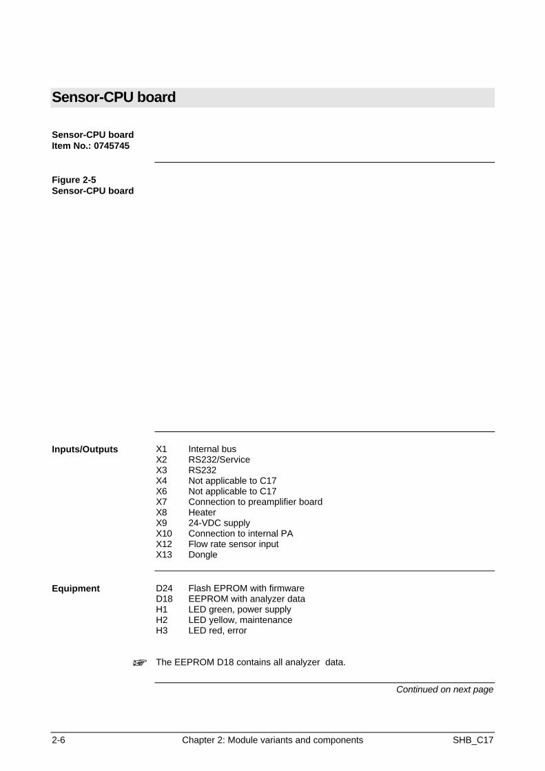
Sensor-CPU board
Sensor-CPU boardItem No.: 0745745
Figure 2-5Sensor-CPU board
Inputs/Outputs X1 Internal busX2 RS232/ServiceX3 RS232X4 Not applicable to C17X6 Not applicable to C17X7 Connection to preamplifier boardX8 HeaterX9 24-VDC supplyX10 Connection to internal PAX12 Flow rate sensor inputX13 Dongle
Equipment D24 Flash EPROM with firmwareD18 EEPROM with analyzer dataH1 LED green, power supplyH2 LED yellow, maintenanceH3 LED red, error
+ The EEPROM D18 contains all analyzer data.
Continued on next page

SHB_C17 Chapter 2: Module variants and components 2-7
Sensor-CPU board, Continued
Figure 2-6Pin layout on module
Continued on next page
2-8 Chapter 2: Module variants and components SHB_C17
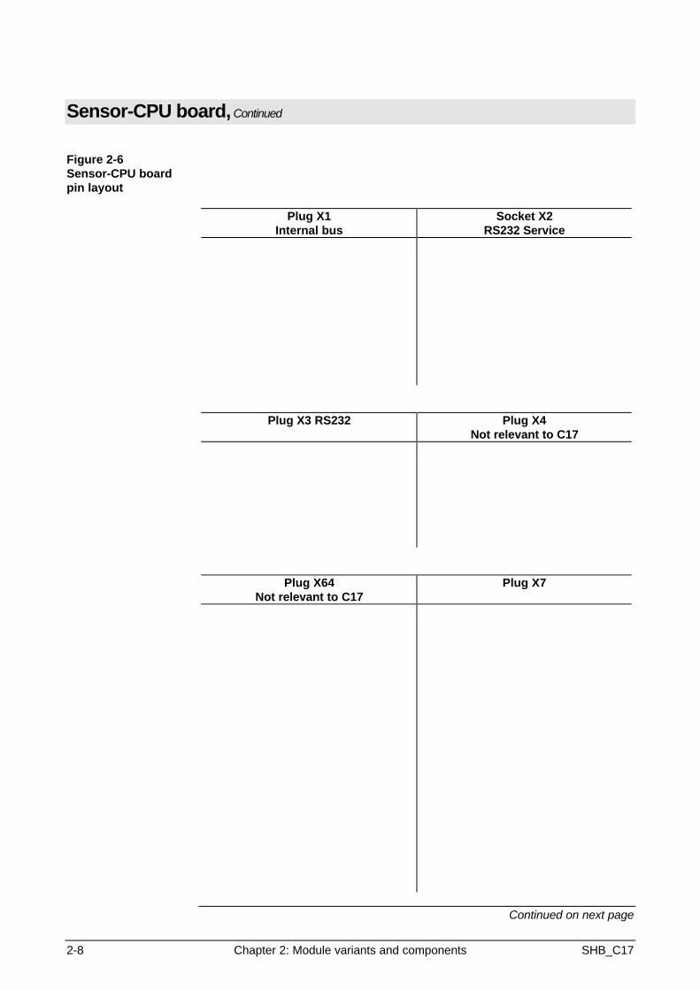
Sensor-CPU board, Continued
Figure 2-6Sensor-CPU boardpin layout
Plug X1Internal bus
Socket X2RS232 Service
Plug X3 RS232 Plug X4Not relevant to C17
Plug X64Not relevant to C17
Plug X7
Continued on next page

SHB_C17 Chapter 2: Module variants and components 2-9
Sensor-CPU board, Continued
Sensor-CPU boardpin layout
Plug X8Heater
Plug X924V
Plug X10Internal PA
Plug X12Flow rate sensor
Continued on next page
2-10 Chapter 2: Module variants and components SHB_C17
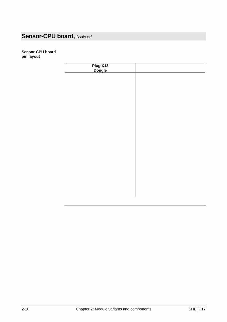
Sensor-CPU board, Continued
Sensor-CPU boardpin layout
Plug X13Dongle
SHB_C17 Chapter 2: Module variants and components 2-11
Flame barriers
Figure 2-7Flame barrier forsample gasItem No. 0768 493andFlame barrier forpurge gasItem No. 0768494
Flame barriers can only be used in the wall-mount, direct connection version.
+ In the Exd module, the purge gas flame barrier is also used for the barometriccorrection outlet.

SHB_C17 Chapter 3: Analyzer variants and assemblies 3-1
Chapter 3: Analyzer and assemblies
Overview
Introduction This chapter describes the analyzer and its assemblies (thermal conductivitysensor, jacket, and preamplifier board).
Chapter contents In this chapter you will find information on the following subjects:
Subject See page
Analyzer, complete 3-2
Components 3-3
3-2 Chapter 3: Analyzer variants and assemblies SHB_C17
Analyzer, complete
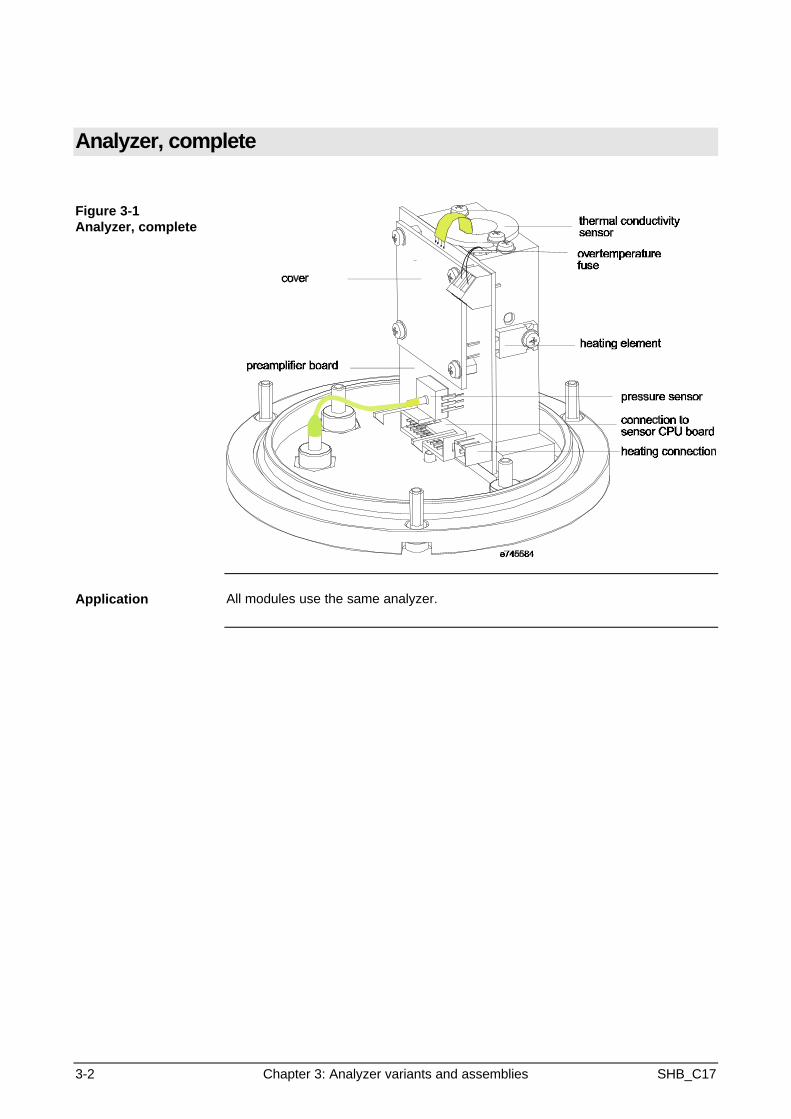
Figure 3-1Analyzer, complete
Application All modules use the same analyzer.
SHB_C17 Chapter 3: Analyzer variants and assemblies 3-3
Components
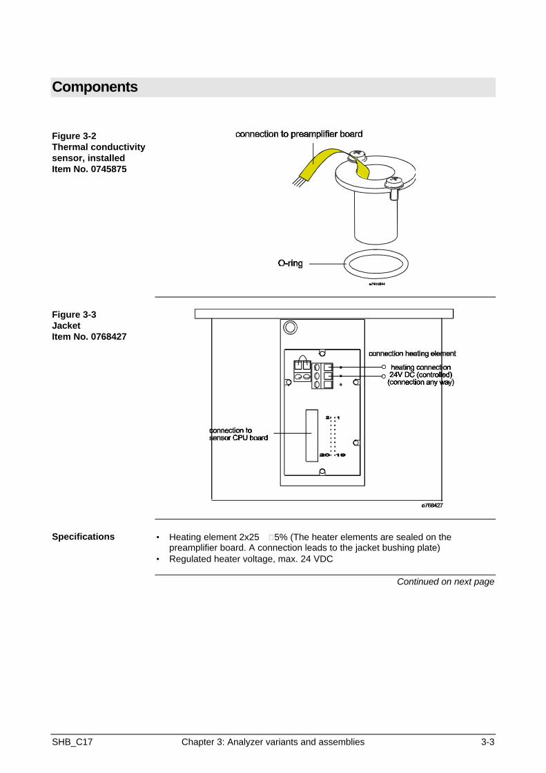
Figure 3-2Thermal conductivitysensor, installedItem No. 0745875
Figure 3-3JacketItem No. 0768427
Specifications • Heating element 2x25 W±5% (The heater elements are sealed on thepreamplifier board. A connection leads to the jacket bushing plate)
• Regulated heater voltage, max. 24 VDC
Continued on next page
3-4 Chapter 3: Analyzer variants and assemblies SHB_C17
Assemblies, Continued
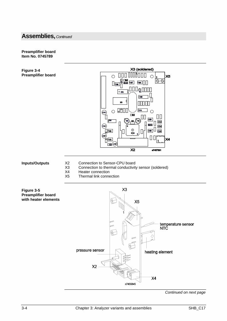
Preamplifier boardItem No. 0745789
Figure 3-4Preamplifier board
Inputs/Outputs X2 Connection to Sensor-CPU boardX3 Connection to thermal conductivity sensor (soldered)X4 Heater connectionX5 Thermal link connection
Figure 3-5Preamplifier boardwith heater elements
Continued on next page

SHB_C17 Chapter 3: Analyzer variants and assemblies 3-5
Components, Continued
Figure 3-6Preamplifier boardpin layout
Plug X2Connection to Sensor-CPU
X3
X4 and X5
SHB_C17 Chapter 4: Troubleshooting 4-1
Chapter 4: Troubleshooting
Overview
Introduction This chapter contains information on troubleshooting and repairing the module.
Chapter Contents In this chapter you will find the following information:
Subject See Page
Status Messages 4-2
Set temperature not reached 4-3
No measurement signal 4-4
Measurement signal unstable/implausible 4-5
No flow rate 4-6

4-2 Chapter 4: Troubleshooting SHB_C17
Status Messages
General StatusMessages
Error Code Status Message Description
0x0001 1 Detector error No interrupt within the time window
0x0002 2 Overrange ADC measurement rangeover/underflow
0x0004 4 Half Half of the drift range exceeded(Offset or Ampl.)
0x0008 8 Over Drift range exceeded (Offset or Ampl.)
0x0010 16 Delta Over Calibration drift exceeded (Offset orAmpl.)
0x0020 32 Floating-point error An error occurred in measurementvalue calculation
Pressure DetectorStatus Messages
General errors except drift errors
Temperature ControlStatus Messages
Error Code Status Message Description
General errors except drift errors
0x1000 4096 Control deviation 1 First limit value exceeded
0x2000 8192 Control deviation 2 Second limit value exceeded
Flow Sensor StatusMessages
General errors except drift errors
C17 Detector StatusMessages
Error Code Status Message Description
General errors except drift errors
0x0040 64 Temp. control error Control deviation 1.1 or Temp.measurement value error
0x0200 512 Pressure comp. error Error in pressure compensationmeasurement value
0x0400 1024 CS comp. error Error in cross-sensitivitycompensation measurement value
0x0800 2048 CG comp. error Error in carrier gas compensationmeasurement value

SHB_C17 Chapter 4: Troubleshooting 4-3
Set temperature not reached
Error Message Plain text for temperature deviation ±2° from set point (60°C)
Status Signal
Possible Cause Corrective Action
Failed power supply Check 24 V on jacket bushing boardCheck connectionsConnect 24-V power supply
The heater voltage regulatorcircuit is on the Sensor-CPU board.There is no permanent 24V to theheater.
Check connections to Sensor-CPUboard.
Defective thermal link Replace thermal link
Temperature sensor defective onpreamplifier board
Check temperature sensorChange preamplifier board
Defective Sensor-CPU board Replace Sensor-CPU board
Defective heating element Check heater element resistanceReplace preamplifier board
Missing connection to Sensor-CPUboard (in jacket)
Establish connection
4-4 Chapter 4: Troubleshooting SHB_C17
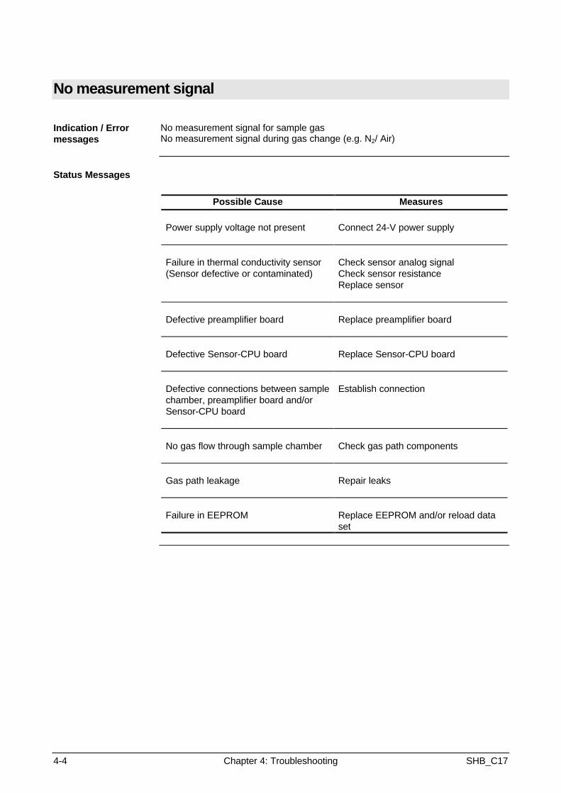
No measurement signal
Indication / Errormessages
No measurement signal for sample gasNo measurement signal during gas change (e.g. N2/ Air)
Status Messages
Possible Cause Measures
Power supply voltage not present Connect 24-V power supply
Failure in thermal conductivity sensor(Sensor defective or contaminated)
Check sensor analog signalCheck sensor resistanceReplace sensor
Defective preamplifier board Replace preamplifier board
Defective Sensor-CPU board Replace Sensor-CPU board
Defective connections between samplechamber, preamplifier board and/orSensor-CPU board
Establish connection
No gas flow through sample chamber Check gas path components
Gas path leakage Repair leaks
Failure in EEPROM Replace EEPROM and/or reload dataset
SHB_C17 Chapter 4: Troubleshooting 4-5
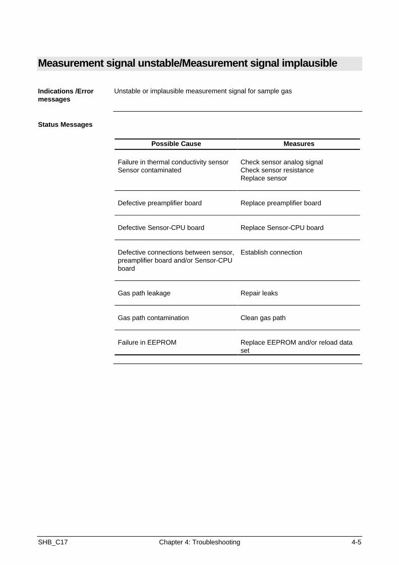
Measurement signal unstable/Measurement signal implausible
Indications /Errormessages
Unstable or implausible measurement signal for sample gas
Status Messages
Possible Cause Measures
Failure in thermal conductivity sensorSensor contaminated
Check sensor analog signalCheck sensor resistanceReplace sensor
Defective preamplifier board Replace preamplifier board
Defective Sensor-CPU board Replace Sensor-CPU board
Defective connections between sensor,preamplifier board and/or Sensor-CPUboard
Establish connection
Gas path leakage Repair leaks
Gas path contamination Clean gas path
Failure in EEPROM Replace EEPROM and/or reload dataset

4-6 Chapter 4: Troubleshooting SHB_C17
No flow rate
Error Message /Indication
Status Message
Possible Cause Measures
Gas path leakage / restriction Repair leakClean contamination
Defective flow rate monitoring insample preparation
Replace flow rate sensorReplace Sensor-CPU board
Sample preparation error Correct error
SHB_C17 Chapter 5: Testing 5-1
Chapter 5: Testing
Overview
Introduction This chapter describes testing of the primary measurement and influence valueson the module.Special accessories will be described in the appropriate places.
Chapter contents In this chapter you will find the following information:
Subject See pageMeasurement signal 5-2
Thermal conductivity resistors 5-4
Thermostat temperature 5-5
Temperature sensor 5-7
Heating elements 5-9

5-2 Chapter 5: Testing SHB_C17
Measurement signal (thermal conductivity sensor)
Electrical value: As voltage drop after the op amp
Where? Sensor-CPU board plug X7 pins +20-3
Set point: Temp. adjustment Uair in V DUair-nitrogen in mV1 0,47 1,32 0,88 3,23 1,00 4,24 1,04 4,5
Test points on plug X7 of CPU-Sensor board can be reached via the adapteror on the thermostat core bushing (pin 1 top right)
An adapter must be used for the rack-mount version.
Figure 5-1Jacket
Continued on next page
SHB_C17 Chapter 5: Testing 5-3
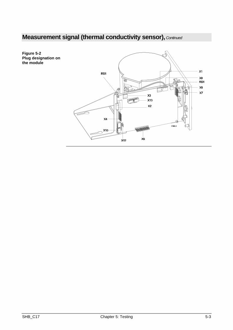
Measurement signal (thermal conductivity sensor), Continued
Figure 5-2Plug designation onthe module
5-4 Chapter 5: Testing SHB_C17
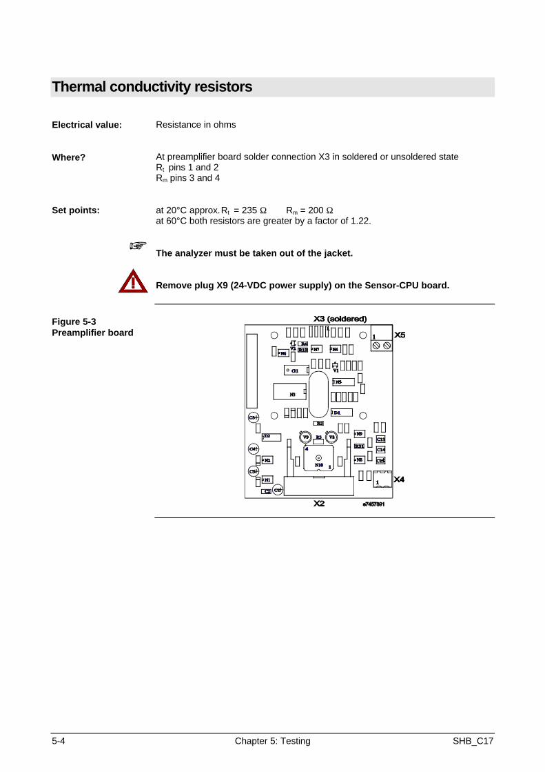
Thermal conductivity resistors
Electrical value: Resistance in ohms
Where? At preamplifier board solder connection X3 in soldered or unsoldered stateRt pins 1 and 2Rm pins 3 and 4
Set points: at 20°C approx.Rt = 235 Ω Rm = 200 Ωat 60°C both resistors are greater by a factor of 1.22.
+ The analyzer must be taken out of the jacket.
Remove plug X9 (24-VDC power supply) on the Sensor-CPU board.
Figure 5-3Preamplifier board
SHB_C17 Chapter 5: Testing 5-5
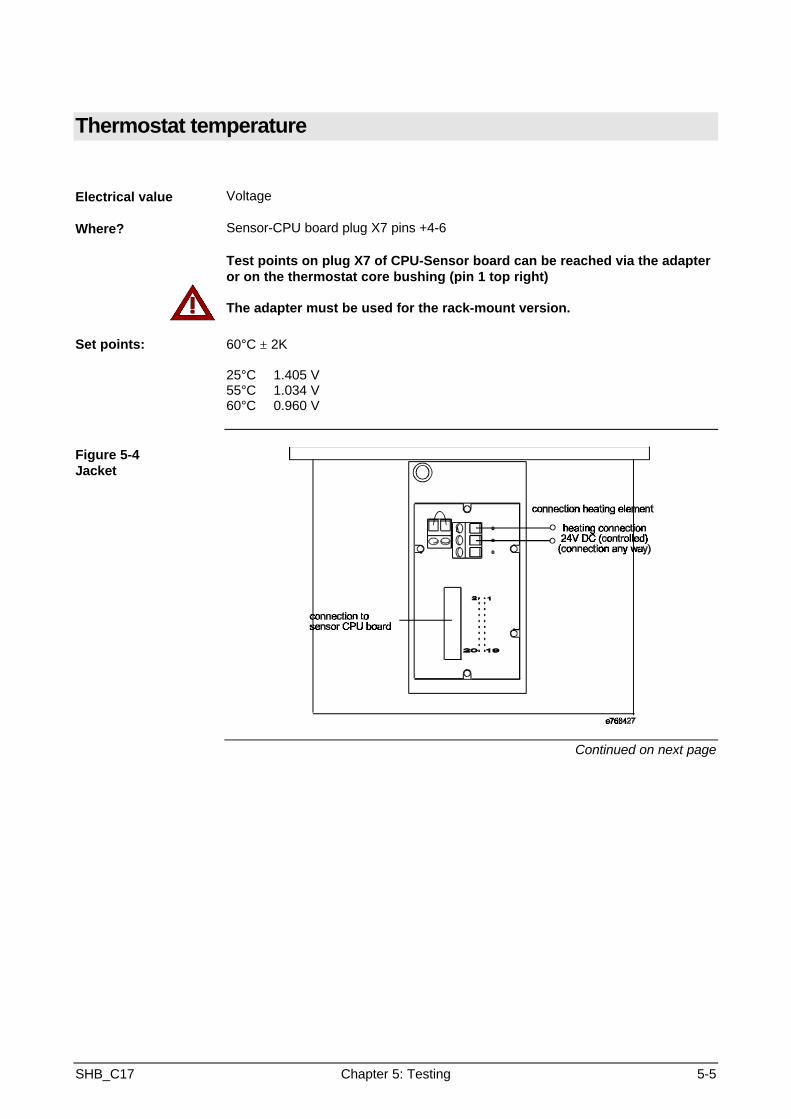
Thermostat temperature
Electrical value Voltage
Where? Sensor-CPU board plug X7 pins +4-6
Test points on plug X7 of CPU-Sensor board can be reached via the adapteror on the thermostat core bushing (pin 1 top right)
The adapter must be used for the rack-mount version.
Set points: 60°C ± 2K
25°C 1.405 V55°C 1.034 V60°C 0.960 V
Figure 5-4Jacket
Continued on next page

5-6 Chapter 5: Testing SHB_C17
Thermostat temperature, Continued
Figure 5-5Plug designation onmodule

SHB_C17 Chapter 5: Testing 5-7
Temperature sensor
Electrical value NTC sensor resistance
Where? Preamplifier board orSensor-CPU board plug X7 pins +4-6
Test points on plug X7 of CPU-Sensor board can be reached via the adapteror on the thermostat core bushing (pin 1 top right)
The adapter must be used for the rack-mount version.
Set point: 25°C 10.0 kΩ55°C 2.99 kΩ60°C 2.49 kΩ61°C 2.40 kΩ64°C 2.16 kΩ
Remove plug X9 (24-VDC power supply) on the Sensor-CPU board.
Figure 5-6Jacket
Continued on next page
5-8 Chapter 5: Testing SHB_C17
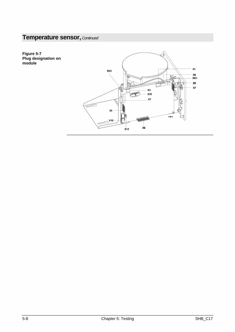
Temperature sensor, Continued
Figure 5-7Plug designation onmodule

SHB_C17 Chapter 5: Testing 5-9
Heating elements
Electrical value Resistance in ohms
Where? Preamplifier board, heating element solder points
Set point: 25 ±5%
Figure 5-8Preamplifier boardwith heater elements
Remove plug X9 (24-VDC power supply) on the Sensor-CPU board.

SHB_C17 Chapter 6: Component replacement 6-1
Chapter 6: Component replacement
Overview
Introduction This chapter describes the steps and procedures for replacing components.
Chapter contents In this chapter you will find the following information:
Subject See page
Complete module removal 6-2
Analyzer removal 6-3
Thermal conductivity sensor replacement 6-5
Thermal link replacement 6-7
Preamplifier board replacement 6-8
Sensor-CPU board replacement 6-10
Flame barrier replacement 6-11
6-2 Chapter 6: Component replacement SHB_C17
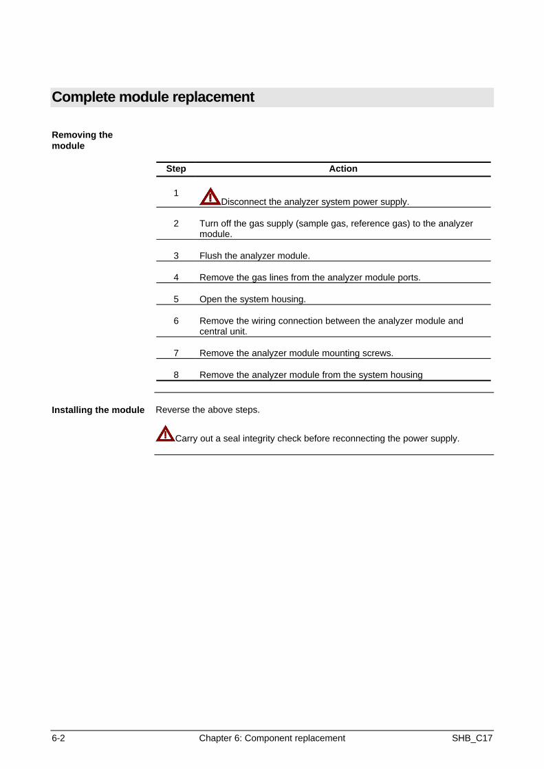
Complete module replacement
Removing themodule
Step Action
1Disconnect the analyzer system power supply.
2 Turn off the gas supply (sample gas, reference gas) to the analyzermodule.
3 Flush the analyzer module.
4 Remove the gas lines from the analyzer module ports.
5 Open the system housing.
6 Remove the wiring connection between the analyzer module andcentral unit.
7 Remove the analyzer module mounting screws.
8 Remove the analyzer module from the system housing
Installing the module Reverse the above steps.
Carry out a seal integrity check before reconnecting the power supply.

SHB_C17 Chapter 6: Component replacement 6-3
Complete analyzer replacement
Analyzer in 19"-rackhousing
Step Action
1 Remove the module from the system housing.
2 Disconnect the hoses from the flange.
3 Remove the three socket-head screws on the flange.
4 Remove the analyzer and flange from the module.
Analyzer in wallhousing,hose connection
Step Action
+ The module must not be removed from the system housing.
1 Remove all hoses from the flange.
2 Remove the three socket-head screws on the flange.
3 Remove the analyzer and flange from the module.
Continued on next page
6-4 Chapter 6: Component replacement SHB_C17
Complete analyzer replacement, Continued
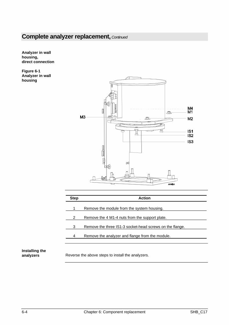
Analyzer in wallhousing,direct connection
Figure 6-1Analyzer in wallhousing
Step Action
1 Remove the module from the system housing.
2 Remove the 4 M1-4 nuts from the support plate.
3 Remove the three IS1-3 socket-head screws on the flange.
4 Remove the analyzer and flange from the module.
Installing theanalyzers Reverse the above steps to install the analyzers.
SHB_C17 Chapter 6: Component replacement 6-5
Thermal conductivity sensor replacement
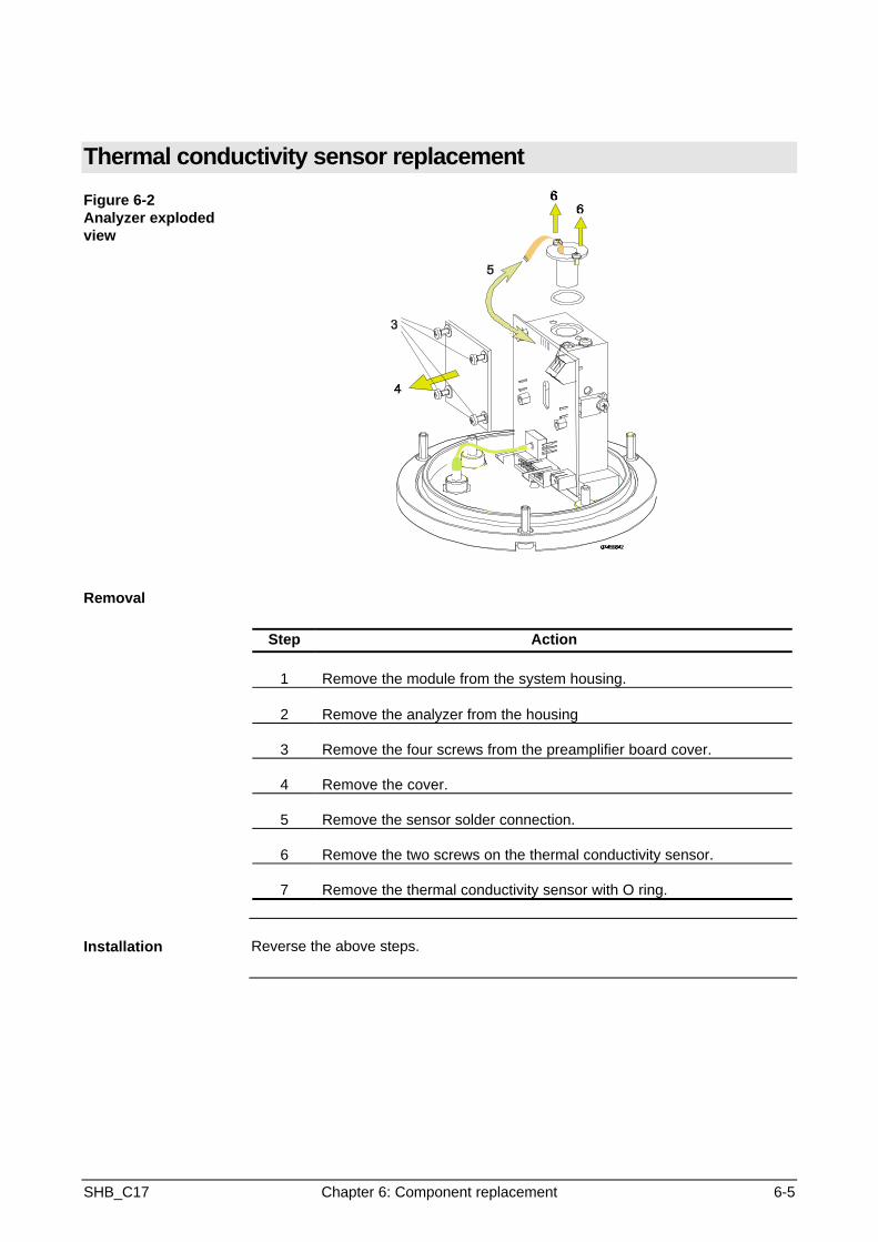
Figure 6-2Analyzer explodedview
Removal
Step Action
1 Remove the module from the system housing.
2 Remove the analyzer from the housing
3 Remove the four screws from the preamplifier board cover.
4 Remove the cover.
5 Remove the sensor solder connection.
6 Remove the two screws on the thermal conductivity sensor.
7 Remove the thermal conductivity sensor with O ring.
Installation Reverse the above steps.

6-6 Chapter 6: Component replacement SHB_C17
Thermal link replacement
Figure 6-3Analyzer explodedview
Removal
Step Action
1 Remove the module from the system housing.
2 Remove the analyzer from the module.
3 Remove screw 1.
4 Slide bracket 2 to one side.
5 Remove the thermal link electrical connections.
6 Remove the thermal link.
Installation Reverse the above steps.
SHB_C17 Chapter 6: Component replacement 6-7
Preamplifier board replacement
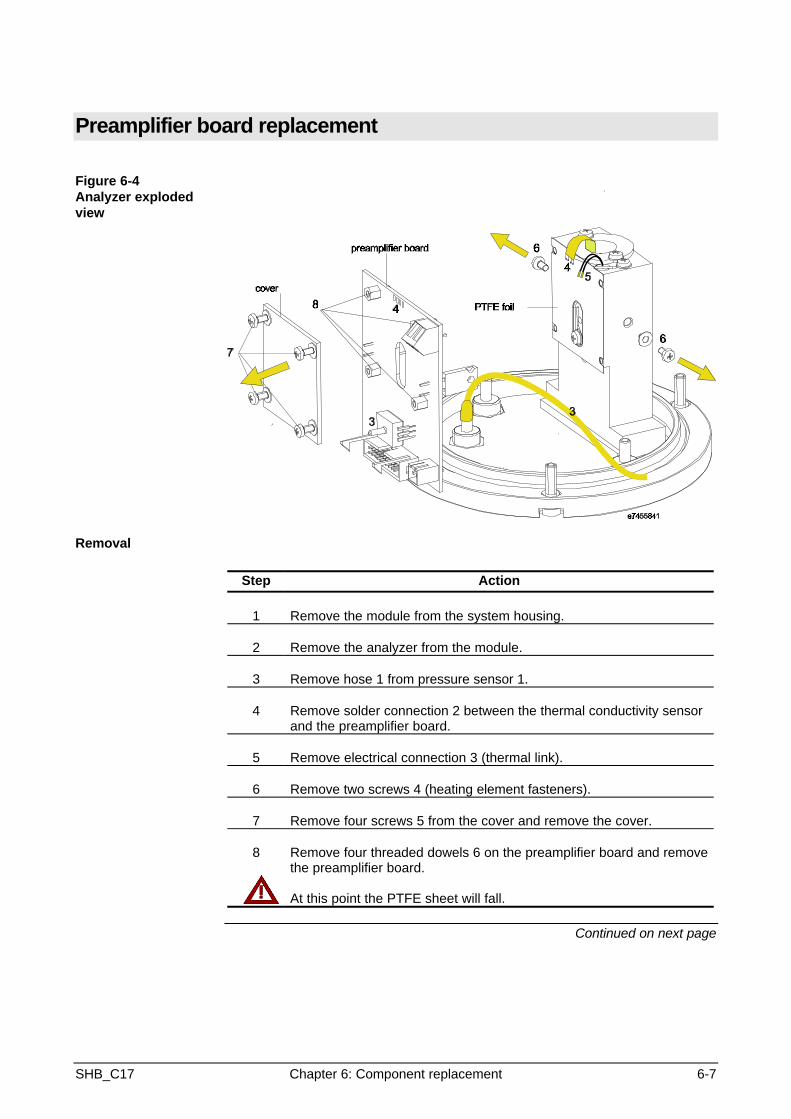
Figure 6-4Analyzer explodedview
Removal
Step Action
1 Remove the module from the system housing.
2 Remove the analyzer from the module.
3 Remove hose 1 from pressure sensor 1.
4 Remove solder connection 2 between the thermal conductivity sensorand the preamplifier board.
5 Remove electrical connection 3 (thermal link).
6 Remove two screws 4 (heating element fasteners).
7 Remove four screws 5 from the cover and remove the cover.
8 Remove four threaded dowels 6 on the preamplifier board and removethe preamplifier board.
At this point the PTFE sheet will fall.
Continued on next page
6-8 Chapter 6: Component replacement SHB_C17
Preamplifier board replacement, Continued
Installation Reverse the above steps.
When installing the heating element be careful of exerting firm pressure onthe chamber.

SHB_C17 Chapter 6: Component replacement 6-9
Sensor-CPU board replacement
Figure 6-5Module view
Step Action
1 Remove the module from the system.
2 Remove all connections from the Sensor-CPU board.
3 Remove knurled screws RS1 and RS2.
4 Remove the Sensor-CPU board.
6-10 Chapter 6: Component replacement SHB_C17
Flame barrier replacement
Being prepared

SHB_C17 Chapter 7: Configuration 7-1
Chapter 7: Configuration
Overview
Introduction This chapter contains instructions for configuring an analyzer module with the testand calibration software.Configuration via the keyboard is described in the operator's manual.
Chapter Contents This chapter contains the following information:
Subject See Page
General 7-2
Caldos 17 Detector 7-3
Temperature Detector 7-6
Pressure Detector 7-7
Flow Detector 7-8
7-2 Chapter 7: Configuration SHB_C17
General
When shouldcalibration beperformed with thePC and software?
• To set up new detectors for auxiliary variables, e.g. when installing a flowsensor
• To set-up new sample components• To change user text• To change the type of communication• To change the balance limits for subsequent calibration
Accessories
+
PC with serial interfaceAdvance Optima - masserv - test and calibration softwareSerial interface connection cable part number 0743091
Configuration can also be carried out via the "Data Set Processing" menu. Theentire data set must then be loaded in the EEPROM.
General Data Serial Number -This serial number can be used for analyzer module Sysconregistration as needed.F4 125 k Baud for CAN bus communicationF5 19200 Baud for communication via a serial interfaceF6 Always select NMT communication if the AO central electronics unit is
connected.F7 Do not changeF8 Free-form user text; for example, the sample site name can be entered
here.
Analyzer ModuleConfiguration
The following detectors are configured:
Caldos 17 DetectorDetectors for auxiliary variables:
Temperature detector 2 control detector for thermostat (always)Pressure detector 1 for atmospheric pressure correction (always)Flow detector 1 for flow monitoring (optional)
Note
+
Each detector must be configured according to the following plan:
Detector ConfigurationComponent Configuration
Measurement Range Configuration
Configuration of a detector is completed only by carrying out the componentand measurement range configuration.

SHB_C17 Chapter 7: Configuration 7-3
Caldos 17 Detector
DetectorConfiguration
Detector ConfigurationF1 Detector: Caldos 17F2 Active Component: (can also be done via the keyboard, has no effect on
subsequent configuration)F3 Detector Correction Parameters - Listing of all active correction functionsF4 Correction Function Activation - Activate desired correction function with "+" or
deactivate with "-"Standard Gas Calibration or Substitute Gas Calibration
F5 Detector Components - Listing of configured components, opening a newcomponentTerminology note:CO2 in N2 and CO2 in Ar are 2 different components!Standard gas (Stdg) is treated as one component.F6 Update Mode / Cycle Time - always "cyclical", 5000 msF7 Delta Offset / Amplification - Standard setting: 15 / 15F8 Over Offset / Amplification - Standard setting: 1000 / 50
Continued on next page
7-4 Chapter 7: Configuration SHB_C17
Caldos 17 Detector, continued
ComponentConfiguration
F5 Select Detector ComponentComponent ConfigurationF1 Component NameF2 Active Measurement Range (can also be done via the keyboard, has noeffect on subsequent configuration)F3 Component Correction Parameters - Listing of all active correctionfunctions
Correction Caldos 17 DetectorF1 Detector Measurement Temperature - Depends onmeasurement, usually "2"Pressure Correction - Pressure Detector 1 must be entered, do notchange any other parameters.Offset / Ampl Common - Variable correction parameters areautomatically entered during subsequent calibration.Linearization
If known, the linearization parameters of the measurementrange to be linearized are entered:F1 Lin. Para A - First linearization parameterF2 Lin. Para B - Second linearization parameterF3 Lin. Start - Start of linearized rangeF4 Lin. End - End of linearized range
Physical measurement value - do not change values enteredLow pass - Enter low pass time, normally 1 s
F4 Activate Correction Functions:Caldos 17 Detector CorrectionPressure CorrectionOffset/Ampl. CommonLinearizationPhysical Measurement ValueLow passNormally all correction functions are activated!
F5 Component Measurement RangeListing of all configured measurement rangesThe last measurement range entered is the reference range for initialcalibration. All other measurement ranges are derived from this one.
A measurement range must also be established for the standard gas.The standard gas measurement ranges are configured as follows:N2 0 - 10,000 rTC (relative thermal conductivity)Air 0 - 10 070 rTCH2 0 - 60 000 rTC
F6 Autorange Active, down, up, enter the applicable "up" and "down"values for active autoranging, the defaults are 20 / 100
F7 Update Mode / Cycle Time - always cyclical, 500 ms
Continued on next page

SHB_C17 Chapter 7: Configuration 7-5
Caldos 17 Detector, continued
LinearizationParameters
All of the following linearization parameters apply to the 0-100 Vol%linearization limits.The smallest possible measurement range is 0-0.3 H2 in N2
Component Lin A Lin B Sensitivity
Air in N2 1.1304 0.7442 +347O2 in N2 0.9558 0.9028 1956CO in N2 0.8746 1.1434 -15074CO2 in N2 1.1494 0.7311 -13522He in N2 2.5771 0.3880 124017H2 in N2 1.9945 0.5014 146135CO in N2 0.9174 1.3864 -1521CH4 in N2 0.9797 1.0207 18641C4H10 in N2 0.5766 1.4890 -8889C3H8 in N2 0.7788 1.0334 -5472SO2 in N2 0.8705 0.9745 -30771H2S in N2 0.7776 1.7943 -19239
Measurement RangeConfiguration
F5 Select Measurement RangeMeasurement Range ConfigurationAs a rule, 0-100 Vol% is set-up as the reference measurement range andthe other ranges (up to four per component) are derived from it.F1 Measurement Range - The reference measurement range appears hereF2 Autorange possible - The selection is yes or noF3 Measurement Range Correction Parameters - Listing of activecorrection functions - Offset / Ampl singl - do not change!F4 Activate Correction Functions - normally Offset / Ampl singl. isconfigured - do not change!F5 Variable measurement range - always enter "No"F6 Var. Measurement Range Start - variable start of measurement rangeF7 Var. Measurement Range End - variable end of measurement range
7-6 Chapter 7: Configuration SHB_C17
Temperature Detector
General Temperature control detector 2 is always configured.
The control parameters should not be changed. They are used to controlthe Caldos 17 analyzer thermostat.
The temperature control 2 detector is not calibrated!
DetectorConfiguration
Detector ConfigurationF1 Detector type: Temperature detector 2 controlF2 Active Component: T-Re. NF3 Detector Correction Parameter: NoneF4 Activate Correction Functions: Function not availableF5 Detector Components: T-Re. NF6 Update Mode / Cycle Time - always "cyclical", 5000 msF7 Delta Offset / Amplification - Standard setting: 75 / 25F8 Over Offset / Amplification - Standard setting: 150 / 50F9 Classification: Auxiliary variable selection
Auxiliary variable indications (then temperature readout appears onscreen)
ComponentConfiguration
F5 Select Detector ComponentComponent ConfigurationF1 Component Name: T-Re. NF2 Active Measurement Range: 0-100°CF3 Component Correction Parameters - Listing of all active correctionfunctions
Standard:Physical measurement value - do not changeControl parameters - Do not change!!F1 KP 500.00000F2 KI 0.00500F3 KD 0.00000F4 Set value 60.0000F5 Max output 4136F6 Min output 0F7 Limit 1 2F8 Limit 2 10
Measurement RangeConfiguration
F5 Component Measurement RangeMeasurement Range ConfigurationF1 Measurement Range: 0-100°CF2 Autorange possible: NoF3 Measurement Range Correction Parameters - Listing of active correctionfunctions - Offset / Ampl singl - do not change!F4 Activate Correction Functions - normally Offset / Ampl singl. is configured -do not change!F5 Variable measurement range - always enter "No"F6 Var. Measurement Range Start - not applicableF7 Var. Measurement Range End - not applicable
SHB_C17 Chapter 7: Configuration 7-7
Pressure Detector
General The pressure detector is used to measure current barometric pressure.The current air pressure is used to correct the measurement signal.
Pressure detector 1 must be configured.The pressure detector must be calibrated after configuration.
DetectorConfiguration
Detector ConfigurationF1 Detector Type: Pressure detector 1F2 Active Component: Air pressureF3 Detector Correction Parameter: NoneF4 Activate Correction Functions: Function not availableF5 Detector Components: Air pressureF6 Update Mode / Cycle Time - always "cyclical", 5000 msF7 Delta Offset / Amplification - Standard setting: 75 / 25F8 Over Offset / Amplification - Standard setting: 150 / 50F9 Classification: Auxiliary variable selection
Auxiliary variable indications (then temperature readout appears onscreen)
ComponentConfiguration
F5 Select Detector ComponentComponent ConfigurationF1 Component Name: Air pressureF2 Active Measurement Range: 0-1250 hPaF3 Component Correction Parameters - Listing of all active correctionfunctions
Standard:Physical measurement value - do not changeLow-pass non-linear filtering
F4 Activate Correction ParametersPhysical Measurement ValueLow-pass non-linear filteringNormally all correction parameters are activated!
F5 Component Measurement Range: 0-1250 hPaF6 Autorange active: NoF7 Update Mode / Cycle Time - always cyclical, 5000 ms
Measurement RangeConfiguration
F5 Component Measurement RangeMeasurement Range ConfigurationF1 Measurement Range: 0-1250 hPaF2 Autorange possible: NoF3 Measurement Range Correction Parameters - Listing of active correctionfunctions - Offset / Ampl singl - do not change!F4 Activate Correction Functions - normally Offset / Ampl singl. is configured -do not change!
The Ampl value entered applies to the type of pressure sensor used!The offset must be calibrated.
F5 Variable measurement range - always enter "No"F6 Var. Measurement Range Start - not applicableF7 Var. Measurement Range End - not applicable

7-8 Chapter 7: Configuration SHB_C17
Flow Detector
General The internal pneumatic module's flow detector can be used to monitor flow throughthe analyzer (approx. 60 l/h). Depending on the flow detector location, configureflow detector 1 or 2.If there is only 1 flow detector located in the pneumatic module, it is flow detector 1.
The flow detector for throughput monitoring (approx. 60 l/h) has a measurementrange of 0-100 l/h.
After configuration, an initial calibration is required!
DetectorConfiguration
Detector ConfigurationF1 Detector Type: Flow Detector 1F2 Active Component: FlowF3 Detector Correction Parameter: NoneF4 Activate Correction Functions: Function not availableF5 Detector Components: FlowF6 Update Mode / Cycle Time - always "cyclical", 5000 msF7 Delta Offset / Amplification - Standard setting: 75 / 25F8 Over Offset / Amplification - Standard setting: 150 / 50F9 Classification: Auxiliary variable selection
Auxiliary variable indications (then temperature readout appears onscreen)
ComponentConfiguration
F5 Select Detector ComponentComponent ConfigurationF1 Component Name: FlowF2 Active Measurement Range: 0-100 l/hF3 Component Correction Parameters - Listing of all active correctionfunctions
Standard:Physical measurement value - do not change
F4 Activate Correction ParametersPhysical Measurement ValueLow-pass timeNormally the physical measurement value is activated!
F5 Component Measurement Range: 0-100F6 Autorange active: NoF7 Update Mode / Cycle Time - always cyclical, 5000 ms
Measurement RangeConfiguration
F5 Component Measurement RangeMeasurement Range ConfigurationF1 Measurement Range: 0-100 l/hF2 Autorange possible: NoF3 Measurement Range Correction Parameters - Listing of active correctionfunctions - Offset / Ampl singl - do not change!F4 Activate Correction Functions - normally Offset / Ampl singl. is configured -do not change!F5 Variable measurement range - always enter "No"F6 Var. Measurement Range Start - not applicableF7 Var. Measurement Range End - not applicable
SHB_C17 Chapter 8: Calibration 8-1
Chapter 8: Calibration
Overview
Introduction This chapter contains instructions for calibrating (initial and subsequent calibration)detector measurement and auxiliary variables
Chapter Contents This chapter contains the following information:
Subject See Page
Caldos 17 Detector Initial Calibration 8-2
Pressure Detector Initial Calibration 8-4
Flow Detector Initial Calibration 8-5
Temperature Detector Initial Calibration 8-6

8-2 Chapter 8: Calibration SHB_C17
Caldos 17 Detector Initial Calibration
When should aninitial calibration becarried out?
• When the measurement task (sample component) needs to be changed• As needed after a sensor change
Accessories • PC with serial interface• Advance Optima - masserv - test and calibration software• Serial interface connection cable part number 0743091• Test gases, test hoses• Flow meter
Preparation • Check gas path seal integrity• Make electrical connections• The analyzer module should be installed in the area of application and
protected from vibration• The analyzer temperature must have reached its set value (64°C) and be
constant.• Test gas flow rates are to be set between 30 and 60 l/h and kept constant ±5 l/h• Connect the PC to the analyzer module• Start the calibration and test software
Test • Test all detectors (the measurement values must be stable and regularlyupdated)
• Status message 0 for all detectors
Performing thestandard gas initialcalibration
+
The standard gas initial calibration takes place at the detector level.The standard gas raw measurement value is calculated and scaled to a valuerepresenting thermal conductivity.
Standard gas calibration must be performed before initial calibration of themeasurement ranges.
Test and calibration softwareMain menuF3 Analyzer Menu
F1 Analyzer CalibrationSelect Caldos 17 DetectorSelect Component Standard GasSelect Standard Gas Calibration (do not select Initial Calibration!!)
F1 Input Standard Gas Set PointN2 10 000Air 10 070H2 60 000
F2 Start initial calibration
Continued on next page
SHB_C17 Chapter 8: Calibration 8-3
Caldos 17 Detector Initial Calibration, continued
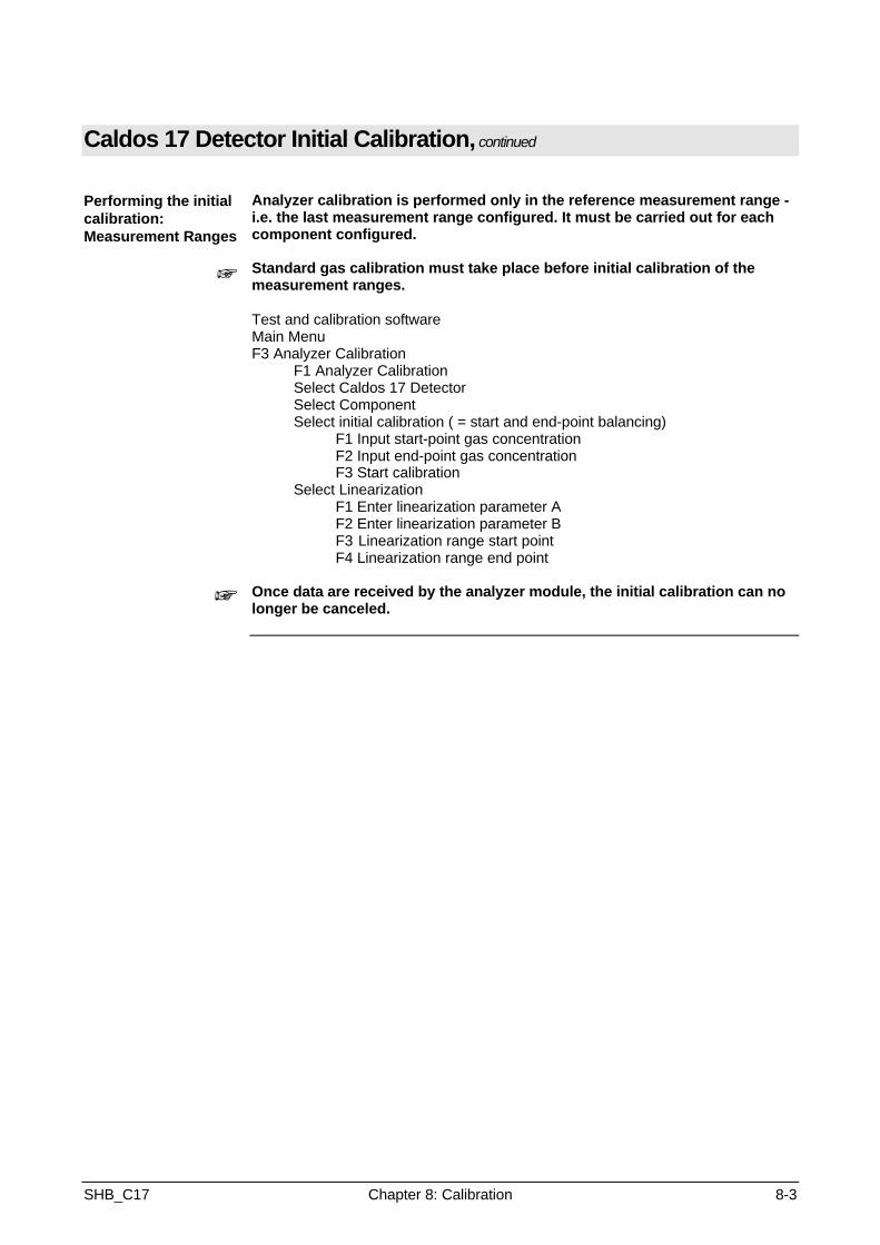
Performing the initialcalibration:Measurement Ranges
+
+
Analyzer calibration is performed only in the reference measurement range -i.e. the last measurement range configured. It must be carried out for eachcomponent configured.
Standard gas calibration must take place before initial calibration of themeasurement ranges.
Test and calibration softwareMain MenuF3 Analyzer Calibration
F1 Analyzer CalibrationSelect Caldos 17 DetectorSelect ComponentSelect initial calibration ( = start and end-point balancing)
F1 Input start-point gas concentrationF2 Input end-point gas concentrationF3 Start calibration
Select LinearizationF1 Enter linearization parameter AF2 Enter linearization parameter BF3 Linearization range start pointF4 Linearization range end point
Once data are received by the analyzer module, the initial calibration can nolonger be canceled.

8-4 Chapter 8: Calibration SHB_C17
Pressure Detector Initial Calibration
When should aninitial calibration becarried out?
After changing the pressure sensor (preamplifier board)
Accessories The pressure detector can be calibrated via the unit keyboard or with a PCand test and calibration software. Both methods are based on the samecalculation and valuation procedures.
Calibration with the PC:• PC with serial interface• Advance Optima - masserv - test and calibration software• Serial interface connection cable part number 0743091• Pressure gauge for the barometric air pressure• Flow meter
Preparation • Make electrical connections• The analyzer module should be installed in the area of application and
protected from vibration• Connect the PC to the analyzer module• Start the calibration and test software
Test • Test all detectors (the measurement values must be stable and regularlyupdated)
• Status message 0 for all detectors
Performing the initialcalibration
+
Only the pressure detector's zero point is calibrated!
Test and calibration softwareMain MenuF3 Analyzer Calibration
F1 Analyzer CalibrationSelect pressure detector 1Select component Air pressureSelect measurement range 0-1100 mbarSelect initial calibration
F1 Input start point set value (current barometric pressure)F5 Start subsequent calibration of start point
The use of F3 requires 2 different pressures and therefore is not effective inthis case.
Once data are received by the analyzer module, the initial calibration can nolonger be canceled.
SHB_C17 Chapter 8: Calibration 8-5
Flow Detector Initial Calibration
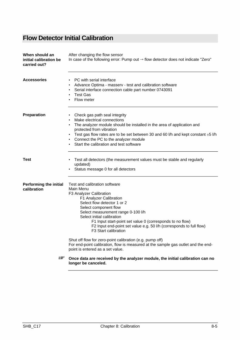
When should aninitial calibration becarried out?
After changing the flow sensorIn case of the following error: Pump out Õ flow detector does not indicate "Zero"
Accessories • PC with serial interface• Advance Optima - masserv - test and calibration software• Serial interface connection cable part number 0743091• Test Gas• Flow meter
Preparation • Check gas path seal integrity• Make electrical connections• The analyzer module should be installed in the area of application and
protected from vibration• Test gas flow rates are to be set between 30 and 60 l/h and kept constant ±5 l/h• Connect the PC to the analyzer module• Start the calibration and test software
Test • Test all detectors (the measurement values must be stable and regularlyupdated)
• Status message 0 for all detectors
Performing the initialcalibration
+
Test and calibration softwareMain MenuF3 Analyzer Calibration
F1 Analyzer CalibrationSelect flow detector 1 or 2Select component flowSelect measurement range 0-100 l/hSelect initial calibration
F1 Input start-point set value 0 (corresponds to no flow)F2 Input end-point set value e.g. 50 l/h (corresponds to full flow)F3 Start calibration
Shut off flow for zero-point calibration (e.g. pump off)For end-point calibration, flow is measured at the sample gas outlet and the end-point is entered as a set value.
Once data are received by the analyzer module, the initial calibration can nolonger be canceled.

8-6 Chapter 8: Calibration SHB_C17
Temperature Detector Initial Calibration
+ The pressure detector should not be calibrated.

SHB_C17 Chapter 9: Parts Catalog 9-1
Chapter 9: Parts Catalog
Parts CatalogCaldos 17 analyzer module
Part number Designation Additional informationPart No.
24704-4-0745875 Thermal conductivity sensor Installed94372-4-0650424 O ring On sensor24704-4-0768427 Jacket Without heater24505-4-0745836 Thermal link24704-4-0768493 Flame barrier For sample gas24704-4-0768494 Flame barrier for purge gas24604-4-0801923 Connector set24705-4-0801945 Connections Internal bus, external and internal24504-4-0801938 Plug, 24 V Installed, with contact strip24704-4-0745789 Circuit board Preamplifier24504-4-0745745 Circuit board Sensor-CPU board20404-4-0743091 Connection Module/PC

Subject to technical changesPrinted in the Fed. Rep. of Germany
43/24-1004-0 EN 10.98