advanced cad laboratory - welcome to iare · pdf fileadvanced cad laboratory lab manual year :...
TRANSCRIPT

1
ADVANCED CAD LABORATORY
LAB MANUAL
Year : 2016 - 2017
Course Code : BST102
Regulations : IARE - R16
Semester : III
Branch : CIVIL ENGINEERING,
(M.Tech Structures)
Prepared by
Mr.SRINIVAS ANGADI, ASSISTNT PROFESSOR
Mr.S. SELVAPRAKASH, ASSISTNT PROFESSOR
INSTITUTE OF AERONAUTICAL ENGINEERING (Autonomous)
Dundigal, Hyderabad - 500 043

2
INSTITUTE OF AERONAUTICAL ENGINEERING (Autonomous)
Dundigal, Hyderabad - 500 043
1. PROGRAM OUTCOMES:
B.TECH - PROGRAM OUTCOMES (POS)
PO-1 Apply the knowledge of mathematics, science, engineeringfundamentals, and an engineering
specialization to the solution of complex engineering problems (Engineering knowledge).
PO-2 Identify, formulate, review research literature, and analyze complexengineering problems reaching
substantiated conclusions using first principles of mathematics, natural sciences, and engineering sciences (Problem analysis).
PO-3 Design solutions for complex engineering problems anddesign system components or processes that
meet the specified needs with appropriate consideration for the public health and safety, and the
cultural, societal, and environmental considerations (Design/development of solutions).
PO-4 Use research-based knowledge and researchmethods including design of experiments, analysis and
interpretation of data, and synthesis of the information to provide valid conclusions (Conduct
investigations of complex problems).
PO-5 Create, select, and apply appropriate techniques, resources, and modernengineering and IT tools including prediction and modeling to complex engineering activities with an understanding of the
limitations (Modern tool usage).
PO-6 Apply reasoning informed by the contextual knowledge to assesssocietal, health, safety, legal and cultural issues and the consequent responsibilities relevant to the professional engineering practice
(The engineer and society).
PO-7 Understand the impact of the professional engineering solutionsin societal and environmental
contexts, and demonstrate the knowledge of, and need for sustainable development (Environment
and sustainability).
PO-8 Apply ethical principles and commit to professional ethics and responsibilities and norms of the
engineering practice (Ethics).
PO-9 Function effectively as an individual, and as a member or leader indiverse teams, and in multidisciplinary settings (Individual and team work).
PO-10 Communicate effectively on complex engineering activities with the engineeringcommunity and with
society at large, such as, being able to comprehend and write effective reports and design documentation, make effective presentations, and give and receive clear instructions
(Communication).
PO-11 Demonstrate knowledge and understanding of theengineering and management principles and apply
these to one’s own work, as a member and leader in a team, to manage projects and in multidisciplinary environments (Project management and finance).
PO-12 Recognize the need for, and have the preparation and ability to engage inindependent and life-long
learning in the broadest context of technological change (Life-long learning).

3
2. PROGRAM SPECIFIC OUTCOMES
PROGRAM SPECIFIC OUTCOMES (PSO's)
PSO-1 Professional Skills: The ability to understand, analyze and develop computer programs in the areas
related to algorithms, system software, multimedia, web design, big data analytics, and networking for efficient design of computer-based systems of varying complexity.
PSO-2 Problem-Solving Skills: The ability to apply standard practices and strategies in software project
development using open-ended programming environments to deliver a quality product for business
success.
PSO-3 Successful Career and Entrepreneurship: The ability to employ modern computer languages, environments, and platforms in creating innovative career paths to be an entrepreneur, and a zest for
higher studies.

4
3. ATTAINMENT OF PROGRAM OUTCOMES AND PROGRAM SPECIFIC OUTCOMES:
S.No Experiment
Program
Outcomes
Attained
Program
Specific
Outcomes
Attained
WEEK-l Program using arrays and function for matrix multiplication PO-2,PO-3 PSO-1
WEEK-2 Programs to draw bending moment and shear force diagrams
graphics in C
PO-2,PO-
3
PSO-1
WEEK-3 Program for design of slab using excel
PO-2
WEEK-4 Program for design of beam using excel PO-3 PSO-1
WEEK-5 Program for design of column using excel PO-
3
PSO-1
WEEK-6 Program for design of footing using excel PO-
3
PSO-1
WEEK-7 Analysis of Truss using STADD pro PO-2,PO-3 PSO-1
WEEK-8 Analysis of Multistoried space frame using STADD pro PO-2,PO-3 PSO-1
WEEK-9 Analysis of Bridge Deck Slab using STADD pro PO-2,PO-3 PSO-1

5
4. MAPPING COURSE OBJECTIVES LEADING TO THE ACHIEVEMENT OF PROGRAM
OUTCOMES:
Course
Objectives
Program Outcomes Program Specific
Outcomes
PO1 PO2 PO3 PO4 PO5 PO6 PO7 PO8 PO9 PO
10
PO
11
PO
12
PSO1 PSO2 PSO3
I √ √ √ √
II √ √ √ √

6
5. SYLLABUS:
ADVANCED CAD LAB
II Semester: M.Tech Structures
Course Code Category Hours / Week Credits Maximum Marks
AIT101 Core L T P C CIA SEE Total
- - 3 2 30 70 100
Contact Classes: Nil Tutorial Classes: Nil Practical Classes: 36 Total Classes: 36
OBJECTIVES:
The course should enable the students to: Learn how to analyze a problem and design the solution for the problem.
I. Analyze the different structural members and give efficient design for the structure
II. Strengthen the ability to identify and apply the suitable algorithm/program/design method for the
given real world problem.
LIST OF EXPERIMENTS
WEEK-1 MATRIX MULTIPLICATION
Program using arrays and function for matrix multiplication
WEEK-2 BENDING MOMENT AND SHEAR FORCE
Programs to draw bending moment and shear force diagrams graphics in C
WEEK-3 DESIGN OF SLAB
Program for design of slab using excel
WEEK-4 DESIGN OF BEAM
Program for design of beam using excel
WEEK-5 DESIGN OF COLUMN
Program for design of column using excel
WEEK-6 DESIGN OF FOOTING
Program for design of footing using excel
WEEK-7 ANALYSIS OF TRUSS
Analysis of Truss using STADD pro
WEEK-8 ANALYSIS OF MULTISTORIED SPACE FRAME
Analysis of Multistoried space frame using STADD pro

7
WEEK-9 ANALYSIS OF BRIDGE DECK SLAB
Analysis of Bridge Deck Slab using STADD pro
Reference Books:
1. Design & Construction of Multistoreyed Buildings- PWD Association – TamilNadu, Chepauk.
2. Structural Design of Multi-storeyed Buildings –Second edition U.H.Varyani-South Asian
Publishers, New Delhi 3. Learn Staad Pro- Rajendran, Design Tech, Civil Cadd centre,Coimbatore-641012
4. Hand book of Reinforced Concrete Design –V.L.Shah & S.R.Karve- Structures Publication,
Pune. 5. Microsoft excel 2013 Bible by John Walkenbanch
Web References:
1. http://www.academia.edu/5782510/Bridge_Design_using_the_STAAD.Pro_Beava_AASHTO_C
ode
2. https://www.academia.edu/5108944/Seismic_analysis_of_plan_irregular_multi-
storied_building_using_STAAD_pro
3. http://onlinecivilforum.com/site/index.php/2016/10/23/rcc-design-excel-sheet/
SOFTWARE AND HARDWARE REQUIREMENTS FOR A BATCH OF 24 STUDENTS:
HARDWARE:
Desktop Computer Systems: 24 nos
SOFTWARE: Application Software: STADD PRO

8
6. INDEX:
S.No Experiment Page No
1 MATRIX MULTIPLICATION 9
2 BENDING MOMENT AND SHEAR FORCE 11
3 DESIGN OF SLAB 17
4 DESIGN OF BEAM 25
5 DESIGN OF COLUMN 31
6 DESIGN OF FOOTING 36
7 ANALYSIS OF TRUSS 42
8 ANALYSIS OF MULTISTORIED SPACE FRAME 58
9 ANALYSIS OF BRIDGE DECK SLAB 62

9
WEEK-1
MATRIX MULTIPLICATION
AIM:
To write a program using arrays and function for matrix multiplication
Hardware & Software required:
Computer with specified configuration with installed C programming language software
ALGORITHM: 1. Start
2. Read the operator to be p
3 Using the switch statement for operator.
a) Case `*’: call mull()
4. Stop
Procudure for Multiplication of Matrices
1. Start
2. Read the value of two matrices using nested for loops
3. Display the two matrices using nested for loop
4. Then multiply two matrices using the following statement using nested
for loop c[i] [j] = c[i] [j] + a[i] [p] *b[p][j]
5. Display the resultant matrix using nested for loops.
6. Stop
C Program for Multiplication of Matrices /*to find product of two matrices*/
void findproduct(int a[][10],int b[][10],int r,int d,int c)
{
int i,j,k;
int m[10][10];
for(i=0;i<r;i++)
for(j=0;j<c;j++)
{
m[i][j]=0;
for(k=0;k<d;k++)
m[i][j]=m[i][j]+a[i][k]*b[k][j];
}
printf("\t**********************************\n");
printf("\tThe product of two matrixes is:\n");
printf("\t**********************************\n");
printmatrix(m,r,c);
}

10
INPUT: Enter the choice + or *
*
OUTPUT: A= 1 1 1 B= 1 0 0
1 1 1 0 1 0
1 1 1 0 0 1
Resultant Matrix is:
1 1 1
1 1 1
1 1 1

11
WEEK-2
BENDING MOMENT AND SHEAR FORCE AIM:
Programs to draw bending moment and shear force diagrams.
Hardware & Software required:
Computer with specified configuration with installed Microsoft Office
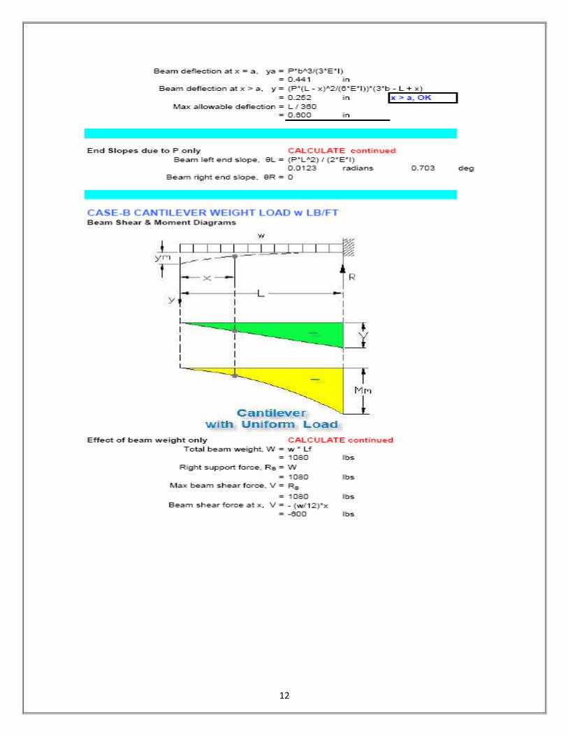
12

13

14

15

16

17
WEEK-3
DESIGN OF SLAB
AIM:
To write a program for design of slab using excel.
HARDWARE & SOFTWARE REQUIRED:
Computer with specified configuration with installed Microsoft Office
PROCUDURE:
Manual Procudere:
Design of Slabs
•Reinforced concrete slabs are classified into
1. One way slabs
2. Two way slabs
3. Flat slabs
4. Flat plates
One way Slabs
•When slabs are supported on two opposite edges continuously or when the load transported in
one direction only on supporting the slab on four edges.
•In one way slabs the direction in which loads are transmitted is called the span.
•One way slabs are usually made to span in the shorter direction since the corresponding bending
moments and shear forces are the least.
•Steel reinforcement is also provided in span direction.
•Reinforcement is also provided in the transverse direction to distribute any unevenness that may
occur in loading and for temperature and shrinkage effects in that direction. Such a steel is called
distribution reinforcement or secondary reinforcement.
•The main reinforcement is calculated based on the bending moment and should not be less than
the minimum specified by the code.
Loading on Slabs

18
•Loading on the slabs consist of
1. Dead weight of the slab
2. Dead weight of floor finishes
3. Weight of fixtures
4. Weight of partitions
5. Live load or imposed load
•Live load varies depending upon the use and types of building.
•For design purpose, live loads are considered as either acting on the full span or assumed to be
absent altogether in the span.
•In continuous slabs, these are so placed as to get the maximum bending moment and shear
effect in the structure.
In the design of slabs for other structures like bridges, the effect of partial loading of the slab
may have to be considered.
•According to IS:875, the loading on slabs for buildings are calculated as follows:
•Self weight at 25kN/m³ for R.C.
•Finishes and portions at 1.5kN/m²
•Characteristic imposed loads, depending upon the type of building.
•For roofs = 1.5kN/m² with access
= 0.75kN/m² without access
•For floors = 2.0 kN/m ² for residential floors
= 3.0 kN/m² for office floors
Arrangement of Loading
•In buildings, the live load is arranged to get critical values of bending moments and shear
forces.
•To get the maximum sagging moment, the alternative should be loaded with live loads.
•To get the maximum hogging moment, alternative adjacent spans should be loaded with live
load.

19
•If the live load is less than three fourth of dead load, then all spans are loaded with live loads, in
addition to dead loads. [i.e. DL>1.33LL]
Analysis of Slabs spanning in one way under udl
•One way slabs are analyzed as beams of unit width.
•IS: 456 allows use of simple coefficient for calculation of moments and forces for continuous
beams and slabs of uniform loading with more or less equal spans and continuous, if the
difference in span are not more than 15 percent of the larger of the spans.
•For obtaining the bending moment, the coefficient shall be multiplied by the total load and
effective span.
•For shear force, the coefficient shall be multiplied by the design load.
Design for shear in slabs
•While designing slabs, thickness is so chosen that the shear can be resisted by concrete itself,
and slab does not need extra shear reinforcements.
•In extreme cases, where thickness tends to be very large that shear reinforcements are allowed
to be used for slabs.
•When the slab thickness is less than 300mm, the slabs show increased shear strength.
•Enhanced shear is equal to kτc, where “k” is called the shear strength enhancement factor.
Table 14: Shear Enhancement Factors
•K varies from 1.30 for 150mm or less to 1.0 for slabs of thickness 300mm or more.
Design of Slabs
According to IS: 456
1.No shear reinforcement should be provided if D ≤ 200m
2.Design slabs without extra shear reinforcement.
3. If D ≥ 200mm, spacing of shear reinforcement can be increased to “d” instead of “0.75d” as in
beams.
4. Maximum shear should not be more than that prescribed in IS:456.

20
5. Spacing for bars in slab for main reinforcement
1.3d or 2.300mm whichever is smaller
6. Spacing of bars in slab for secondary steel
1.5d or 2.450mm whichever is smaller
1. Minimum cover to the steel in slabs is 20mm.
2. Minimum distribution steel is 0.15% of bD for MS and 0.12% of bD for HYSD.
3. Diameter of reinforcing bars shall not exceed one eight the total thickness.
4. Basic effective span–to–depth ratios is applicable to slabs also.
5. is useful for calculating the required area of steel reinforcement.
Design of One Way Slabs
1. Assume depth based on deflection and percent steel.
2. Determine maximum BM assuming one meter width and effective span.
3. Determine effective depth of slab from Mu= kfckbd2 and b = 1000mm, find D = d + Cover.
4. Check slab depth for shear
5. Determine depth for satisfying all requirements and determine steel required for the moment.
6. Check for minimum distribution steel.
7. Select a suitable diameter of main reinforcement and determine its spacing.
Moments in Two way Restrained Slabs with Corners Held Down
Analysis by Coefficients
•Restrained slabs are defined in codes as those slabs which are cast integral with RC frames and
which are not free to lift up at the corners.
•These slabs may be continuous or discontinuous at the edges. Those which are discontinuous at
edges are also referred to be simply supported.
•Coefficients specified in IS:456-2000, Table 26 in Annexure D can be used for analysis of such
slabs.
Moments in Two way Restrained Slabs with Corners Held Down

21
Analysis by Coefficients
•Conditions to be satisfied for use of these coefficients are:
1.Loading on adjacent spans should be the same
2.Span in each direction should be approximately equal.
•The span moment per unit width and the negative moments at continuous edges for the slabs are
calculated from the equations in terms of “lx”,
for short span
for longer span
Design of Two-way Slabs
•Restrained two way slab is divided into middle strip and edge strips. Middle strip is forming
three-fourth of slab width in width directions.
•Torsion steel must be provided at discontinuous edges as specified in code.
•Coefficients are given in Table 26 of IS: 456-2000. These coefficients are derived from the
yield line theory of slabs.
•Table given for coefficients is applicable for slabs carrying uniformly distributed loads not for
concentrated loads, for which analysis should be done, separately.
•Span moments/edge moments per unit width are calculated by determining ratio of “ly” and
“lx” and for different edge conditions.
Coefficients for Moments
•Slabs restrained against corners lifted up
•nd = Number of discontinuous edges = 0,1,2,3 and 4.
• C = 1.0 for a discontinuous edge
= √(7/3) for continuous edge
•Subscripts “s” and “l” denote “short edge” and “long edge”

22
•Subscripts “1” and “2” represent two edges in short and longer direction
Important Design Issues from Table 26
1.Edge moments of continuous supports are 1.33 times the span moments.
2.Long span moment coefficient”αy” is a constant for given end conditions of slab, irrespective
of the span ratios.
3.Short span coefficient varies sharply with variation of the ratio of spans
4.While using Table 26 for a series of slabs, moments calculated at an interior support will
sometimes be different on two sides of that support because of the differences in continuity
condition of slabs on opposite sides of support.
Arrangement of Reinforcements
•While using design of two-way slabs with the help of coefficients, restrained slabs are
considered to be divided into middle and edge strips.
•Moments given in Table 26 apply only to middle strips, and no further redistribution is allowed
for these moments.
•Edge strips have to be reinforced only with nominal minimum steel for crack control.
Arrangement of Reinforcements
•Middle strip should have steel (+ve and –ve ) calculated for various sections. In edge strips ,
steel is placed as positive steel at the bottom of slab.
•Negative moments may be experienced at discontinuous edges since, in practice, they are not
supported on rollers but partially restrained at their ends. The magnitude of this moment depends
on the degree of fixity at the edge of the slab and is intermediate.
Arrangement of Reinforcement
•Usual practice is to provide at these edges top reinforcement for negative moment equal to
As per IS:456.2000, 50 percent of the steel provided at mid span should be extended along these
edges, and the negative steel has to extend into the span 0.1 times the span length from the face
of the beam.
Design of Two-way Slabs
•The slab thickness should be calculated based on the greater value of the negative B.M on the
short span.
Hence

23
•Total thickness = d (short) + 0.5ø + cover
•Total thickness = d (long) + 0.5ø + ø + cover
The slab should satisfy span/effective depth ratio to control deflection.
–Simply supported = 28
–Continuous = 32
•Depth of slab selected from deflection criterion will be generally greater than the minimum
required from strength criterion.
•Short span steel will be placed in the lower layer.
Restrained moments are obtained for the middle strips only. The reinforcement is distributed
uniformly in the middle strips.
•Each direction is to be provided only with the minimum reinforcement placed at the bottom of
the slabs. In addition, corner steel reinforcement should be provided at the discontinuous edges.
Corner reinforcement consists of two mats, are placed on the top and the other at the bottom of
the slab, with each mat having steel in both x and y directions.
•Where the slab is discontinuous on both sides of a corner, fall torsion steel has to be provided.
The area of the full torsion reinforcement per unit width in each of the four layer should be as
follows.
•(Area of full corner steel ) = [3/4][Area required for the maximum span per unit width in each
of four layers]
•These steels are to be provided for a distance of one-fifth the short span .
Based on the Manual Procudere, excel sheet should be designed

24

25
WEEK-4
DESIGN OF BEAM
AIM:
To write a program for design of beam using excel.
HARDWARE & SOFTWARE REQUIRED:
Computer with specified configuration with installed Microsoft Office
PROCUDURE:
Manual Procudere:
DESIGN FOR BEAM
RCC beam is subjected to bending moments and shear.
Due to the vertical external load, bending compresses the top fibers of the beam and
elongates the bottom fibers.
The strength of the RCC beam depends upon the composite action of concrete and
steel.
WORKING STRESS METHOD
• The Stresses in an element is obtained from the working loads and compared with
permissible stresses.
• The method follows linear stress-strain behavior of both the materials.
• Modular ratio can be used to determine allowable stresses.
• Material capabilities are under estimated to large extent. Factor of safety are used in
working stress method.
• The member is considered as working stress.
• Ultimate load carrying capacity cannot be predicted accurately.
• The main drawback of this method is that it results in an uneconomical section
LIMIT STATE METHOD • The stresses are obtained from design loads and compared with design strength.

26
• In this method, it follows linear strain relationship but not linear stress relationship (one
of the major difference between the two methods of design).
• The ultimate stresses of materials itself are used as allowable stresses.
• The material capabilities are not under estimated as much as they are in working stress
method. Partial safety factors are used in limit state method.
LOAD ACTING ON A STRUCTURE
DEAD LOAD:
DEAD Load is self-weight of the various components in the building.
LIVE LOAD: LIVE Load is the external superimposed load on a structure.
Uniformly distributed load.
Uniformly varying load.
Concentrated load.
Arbitrary load.
TYPES OF BEAMS Simply Supported Beam.
Fixed Beam.
Cantilever Beam.
Continuous Beam.
Overhanging Beam.

27
Cantilever, Simply supported beam
SIMPLY SUPPORTED BEAM It is a beam that is freely supported at two ends on walls or columns.
In actual practice no beam rests freely on the supports ( columns or walls )
FIXED BEAM
In this beam both ends of the beam are rigidly fixed into the supports.
Main reinforcement bars and stirrups are also provided
CANTILEVER BEAM: One end of the beam is fixed to wall or column and the other end is free.
It has tension on top and compression on bottom

28
CONTINIOUS BEAM
A continuous beam is a statically indeterminate multi span beam on hinged support.
The end spans may be cantilever, may be freely supported or fixed supported. At least
one of the supports of a continuous beam must be able to develop a reaction along
the beam axis.
OVERHANGING BEAM:
In overhanging beam its end extends beyond column or wall support.
Overhanging of the beam is the unsupported portion of the beam, it may be on side or
both the sides.
TYPES OF RCC BEAMS:
SINGLY REINFORCED BEAM:
Singly reinforcement beam have steel provided only one side tension an another side
compression. tension takes steel load or tensile load and compression takes concrete or
compressive load.
DOUBLY REINFORCED BEAM
• Doubly reinforced sections contain reinforcement both at the tension and at the
compression face, usually at the support section only

29

30

31
WEEK-5
DESIGN OF COLUMN
AIM:
To write a program for design of Column using excel.
HARDWARE & SOFTWARE REQUIRED:
Computer with specified configuration with installed Microsoft Office
PROCUDURE:
Manual Procudere:
Design of column
Reinforced Concrete Columns
A column is a very important component in a structure. It is like the legs on which a structure
stands. It is designed to resist axial and lateral forces and transfer them safely to the footings in
the ground.
You can manually calculate the superimposed loads on a column in a structure using a simple
process outlined in this linked article. You might also like this RCC Column design app which
can then be used to calculate longitudinal steel reinforcement in a column for a given axial load.
Columns support floors in a structure. Slabs and beams transfer the stresses to the columns. So, it
is important to design strong columns.

32
Reinforced Cement Concrete Column Plan and Section
A column is defined as a compression member, the effective length of which
exceeds three times the least lateral dimension. Compression members whose
lengths do not exceed three times the least lateral dimension may be made of
plain concrete.
The axial load carrying capacity of a column is deduced from the formula
Please see the link for formulas to calculate axial loads in columns. I would recommend using
advanced structural design software like ETabs or Staad Pro for design of structures. Column
design does not depend only on axial loads, but also on many other factors. There are bending
moments and tortional forces induced due to beam spans, wind loads, seismic loads, point loads
and many other factors.
In this article, we are going to discuss in detail the basis of classification of columns and
different types of reinforcement required for a certain type of column.
A column may be classified based on different criteria such as:
1. Based on shape
Rectangle
Square
Circular
Polygon
2. Based on slenderness ratio

33
The ratio of the effective length of a column to the least radius of gyration of its cross section is
called the slenderness ratio.
Short RCC column, =< 10
Long RCC column, > 10
Short Steel column, =<50
Intermediate Steel column >50 & <200
Long Steel column >200
3. Based on type of loading
Axially loaded column
A column subjected to axial load and unaxial bending
A column subjected to axial load and biaxial bending
4. Based on pattern of lateral reinforcement
Tied RCC columns
Spiral RCC columns
Minimum eccentricity
Emin > l/500 + D/30 >20
Where, l = unsupported length of column in ‘mm’
D = lateral dimensions of column
Types of Reinforcements for columns and their requirements
Longitudinal Reinforcement
Minimum area of cross-section of longitudinal bars must be atleast 0.8% of gross section
area of the column.
Maximum area of cross-section of longitudinal bars must not exceed 6% of the gross cross-
section area of the column.
The bars should not be less than 12mm in diameter.
Minimum number of longitudinal bars must be four in rectangular column and 6 in circular
column.
Spacing of longitudinal bars measures along the periphery of a column should not exceed
300mm.
Transverse reinforcement
It may be in the form of lateral ties or spirals.
The diameter of the lateral ties should not be less than 1/4th of the diameter of the largest
longitudinal bar and in no case less than 6mm.
The pitch of lateral ties should not exceed
Least lateral dimension

34
16 x diameter of longitudinal bars (small)
300mm
Helical Reinforcement
The diameter of helical bars should not be less than 1/4th
the diameter of largest longitudinal and
not less than 6mm.
The pitch should not exceed (if helical reinforcement is allowed);
75mm
1/6th of the core diameter of the column
Pitch should not be less than,
25mm
3 x diameter of helical bar
Pitch should not exceed (if helical reinforcement is not allowed)
Least lateral dimension
16 x diameter of longitudinal bar (smaller)
300mm

35

36
WEEK-6
DESIGN OF FOOTING
AIM:
To write a program for design of Footing using excel.
HARDWARE & SOFTWARE REQUIRED:
Computer with specified configuration with installed Microsoft Office
Reinforced Concrete Footings
Footing comprises of the lower end of a column, pillar or wall which i enlarged with projecting courses
so as to distribute load.
Footings shall be designed to sustain the applied loads, moments and forces and the induced
reactions and to ensure that any settlement which may occur shall be as uniform as possible and
the safe bearing capacity of soil is not exceeded.
In sloped or stepped footings, the effective cross-section in compression shall be limited by the
area above the neutral plane, and the angle of slope or depth and location of steps should be such
that the design requirements are satisfied at every section.
Design Procedure of Column Footings | Foundation Design
Here is a step-by-step guide to Column Footing Design:

37
Step 1
Area required for footing
Square = B = (w+w1)/P0
Where, Po = safe bearing capacity of soil
w1 = self weight of footing
w = self weight of footing
For Rectangle = b/d = B/D
A = b x d
Net upward pressure on the footing
q/p = W/A
Step 2
Bending Moment
Critical section for maximum bending moment is taken at the face of the column
For a square footing,
Mxx = q x B/8 (L – a)2
Mxx = q x L/8 (B – b)2
Myy = q x B/8 (L – a)2
Step 3
To fix the depth of the footing shall be greater of the following:
Depth from bending moment consideration
d = √(M/Qb)
where, Q = moment of required factor
Depth from shear consideration
Check for one way shear
Check for two way shear or punching shear

38
Critical shear for one way shear is considered at a distance ‘d’ from face of the column.
Shear force, V = qB [ ½(B – b) d]
Nominal shear stress, Tv = k . Tc
Tc = 0.16√fck
Step 4
Check for two way shear
Critical section for two way shear is considered at a distance at a distance d/2 from all the faces
of the column.
SF, V = q [ B2 – (b + d)
2]
SF, V = q [L x B – (a + d)(b + d)]
Nominal shear stress, Tv = V/2((a+d)(b+d)d) ——- {for a rectangle
Tv = V/4((b+d)d) ——- {for a square
Tv = k . Tc
k = 0.5 + β > 1 ; [Beta β = ratio of sides of the column
Tc = 0.16√fck
Area of steel, Ast = M/((σ)stjd)

39

40

41
42
WEEK-7
ANALYSIS OF TRUSS
.
AIM:
To determine the Analysis of Truss using STADD pro
APPARATUS:
STADD pro software, compute,
PROCEDURE:
1. Entering Job information.
2. Truss model geometry
3. Defining member properties ,sections
4. Assigning Loads(Load Cases and combination)
5. Defining Pre-Analysis Print out, analysis type and Post-Analysis print out
6. Defining Design Requirements
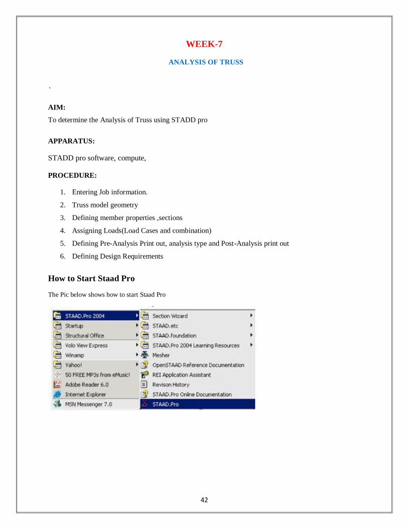
How to Start Staad Pro
The Pic below shows how to start Staad Pro

43
In New File select
1. Truss
2. Units (here KN and mm in this example)
The staad Graphical interface will appear as shown in below picture

44
1. Entering Job Information
Building Model (structure) Geometry
Defining Truss Geometry
One of the methods that you can construction lines and then draw on these lines the truss members
Noting that the no. of construction lines is excluding Ist line..

45
After clicking Snap Node/Beam ,use the mouse and connect between nodes created at the intersections of
construction lines

46
How to see Diagram Labels (Nodes Numbers, Beam Numbers etc)
Node and beam labels are a way of identifying the entities we have drawn on the screen, and very useful
when dealing with the output results

47
3. Defining member properties, sections
Property
In which we can define or choose sections properties of the members of the truss.
Spec.: In which we can define or choose members’ specifications.
Support: In which we can define the supports properties (restraints).
Load: In which we can define the applied loads, load cases, load combinations.
Material In which we can define the material properties (ex. E, density, etc.)
Assume Preliminary
Sections:
All Top and Bot chords are one size L 55*55*3

48
All Diagonals and verticals are one size L 45 * 45* 3
Assigning the sections created to the model
Supports
By clicking on the support icon the shown window will appear. We have to create new kinds of supports

49
Use the mouse and click on the nodes according to its support type as shown below

50
4. Defining Loads
The creation and assignment of load cases involves the following two steps:
1. First, we will be creating all 3-load cases.
2. Then, we will be assigning them to the respective members/nodes
For example
Dead Load Case can be Load Case No.1

51
Live Load Case can be Load Case No. 2 and Wind Load is the Case No.3
Also, we can define load combinations according to required.
For example, we can create a load combination
1.25 D.L. + 1.5 L.L + 0.8 W.L.

52
And In Dead Load Create the Self weight as
In each Load Case Create the Nodal Loads on truss as specified before. Make sure of the direction of
forces according to global coordinates

53
After Creating the commond of (Perform Analysis-Check);We have to assign the members that want to
be this type of analysis for it.
Click Assign and then use the cursor and choose all the members,thus all the members should be
highlighted as shown below.

54
Pre-Print
To add the Pre-Print Commond click" Define Commands"
For example here we have choosen to print the support reactions,member forces,joint displacements
Post Print Commands
Support reactions
Analysis results
Member Forces
Max Forces

55
Add which property you need and then use cursor to ASSIGN to which member in the truss
6. Defining Design Requirements
Steps
1. To Specify steel design parameters, go to Design/Steel page from the left side of the screen. Make sure
that under the Current Code selections on the top right hand side ,Canadian is selected.
There are many Design Commands in the STAAD Design subroutine. Here, we will use only to Check
Code, regarding adequacy of members.

56
7-Analysis & Viewing Results
STAAD Performs Analysis and Design simultaneously. In order to Perform Analysis and Design, select
the Run Analysis option from the Analyze menu
When you select the Run Analysis option from the Analyse menu, the following dialog box appears. We
are presented with the choice of 2 engines. The STAAD engine and the STARDYNE Advanced
Analysis engine. The STARDYNE Analysis engine is suitable for advanced problems such as Buckling
Analysis, ModaL Extraction using various method ,etc
STAAD engine is suitable for this tutorial. Click on th Run Analysis button.

57
The soloving process is shown in pop up screen.
Visualization of Some Results

58
WEEK-8
ANALYSIS OF MULTISTORIED SPACE FRAME
AIM:
Analysis of Multistoried space frame using STADD pro
HARDWARE & SOFTWARE REQUIRED:
Computer with specified configuration with installed STADD Pro Software
PROCUDURE AND ANALYSIS STEPS
STAAD Staad is powerful design software licensed by Bentley .Staad stands for structural analysis and
Design Any object which is stable under a given loading can be considered as structure. So first
find the outline of the structure, where as analysis is the estimation of what are the type of loads
that acts on the beam and calculation of shear force and bending moment comes under analysis
stage. Design phase is designing the type of materials and its dimensions to resist the load. this
we do after the analysis.
To calculate s.f.d and b.m.d of a complex loading beam it takes about an hour. So when it
comes into the building with several members it will take a week. Staad pro is a very powerful
tool which does this job in just an hour’s staad is a best alternative for high rise buildings.
Now a days most of the high rise buildings are designed by staad which makes a
compulsion for a civil engineer to know about this software.
These software can be used to carry rcc ,steel, bridge , truss etc according to various country
codes.
Staad foundation:
Staad foundation is a powerful tool used to calculate different types of foundations. It is
also licensed by Bentley software’s. All Bentley software’s cost about 10 lakhs and so all
engineers can’t use it due to heavy cost.
Analysis and design carried in Staad and post processing in staad gives the load at
various supports. These supports are to be imported into these software to calculate the footing
details i.e., regarding the geometry and reinforcement details.
This software can deal different types of foundations
SHALLOW (D<B)
1. Isolated (Spread) Footing
2.Combined (Strip) Footing
3.Mat (Raft) Foundation
DEEP (D>B)
1.Pile Cap
2. Driller Pier
1. Isolated footing is spread footing which is common type of footing.
2. Combined Footing or Strap footing is generally laid when two columns are very near to each

59
other.
3. Mat foundation is generally laid at places where soil has less soil bearing capacity.
4. pile foundation is laid at places with very loose soils and where deep excavations are required.
So depending on the soil at type we has to decide the type of foundation required.
Also lot of input data is required regarding safety factors, soil, materials used should be
given in respective units.
After input data is give software design the details for each and every footing and gives
the details regarding
1. Geometry of footing
2. Reinforcement
3. Column layout
4. Graphs
5. Manual calculations
These details will be given in detail for each and every column.
Another advantage of foundations is even after the design; properties of the members can be
updated if required.
The following properties can be updated
Column Position
Column Shape
Column Size
Load Cases
Support List
The multistoreyed frame represents the center line diagram of the building in staad pro. Each
support represents the location of different columns in the structure. This structure is used in
generating the entire structure using a tool called transitional repeat and link steps. After using
the tool the structure that is created can be analyzed in staad pro under various loading cases.
Below figure represents the skeletal structure of the building which is used to carry out the
analysis of our building.
All the loadings are acted on this skeletal structure to carry out the analysis of our building.
This is not the actual structure but just represents the outline of the building in staad pro.
A mesh is automatically created for the analysis of these building.

60
Load Conditions and Structural System Response : The concepts presented in this section provide an overview of building loads and their
effect on the structural response of typical wood-framed homes. As shown in Table, building
loads can be divided into types based on the orientation of the structural action or forces that they
induce: vertical and horizontal (i.e., lateral) loads. Classification of loads are described in the
following sections.
Building Loads Categorized by Orientation:
Types of loads on an hypothetical building are as follows.
Vertical Loads
Dead (gravity)
Live (gravity)
Snow(gravity)
Wind(uplift on roof)
Seismic and wind (overturning)
Seismic( vertical ground motion)
Horizontal (Lateral) Loads: Direction of loads is horizontal w.r.t to the building.
Wind
Seismic(horizontal ground motion)
Flood(static and dynamic hydraulic forces
Soil(active lateral pressure)
Dead load calculation
Weight=Volume x Density
Self weight floor finish=0.12*25+1=3kn/m^2
The above example shows a sample calculation of dead load. Dead load is calculated as per IS 875 part 1
Generally for any structure live load is taken as 25 N/mm for design.
Live loads are calculated as per IS 875 part 2
Wind loads: In the list of loads we can see wind load is present both in vertical and horizontal loads.
This is because wind load causes uplift of the roof by creating a negative(suction) pressure on the
top of the roof
After designing wind load can be assigned in two ways
1. collecting the standard values of load intensities for a particular heights and assigning of the
loads for respective height.
2. calculation of wind load as per IS 875 part 3.
We designed our structure using second method which involves the calculation of wind load
using wind speed.
In Hyderabad we have a wind speed of 45 kmph for 10 m height and this value is used in Calculation

61
Floor load: Floor load is calculated based on the load on the slabs. Assignment of floor load is done
by creating a load case for floor load. After the assignment of floor load our structure looks as
shown in the below figure.
The intensity of the floor load taken is: 0.0035 N/mm2
-ve sign indicates that floor load is acting downwards
Load combinations: All the load cases are tested by taking load factors and analyzing the building in different
load combination as per IS456 and analyzed the building for all the load combinations and
results are taken and maximum load combination is selected for the design
Load factors as per IS456-2000
When the building is designed for both wind and seismic loads maximum of both is taken.
Because wind and seismic do not come at same time as per code. Structure is analyzed by taking all the above combinations.

62
WEEK-9
ANALYSIS OF BRIDGE DECK SLAB
AIM:
Analysis of Bridge Deck Slab using STADD pro
HARDWARE & SOFTWARE REQUIRED:
Computer with specified configuration with installed STADD Pro Software
PROCUDURE AND ANALYSIS STEPS
The combination of STAAD.pro and STAAD.beava can make your bridge design and analysis
easier. STAAD.pro is first used to construct the bridge geometry and STAAD.beava is used to
find the AASHTO 2002 load positions that will create the maximum load response. The
maximum load response could be any of the following:
1. Maximum plate stresses, moment about the local x axis of a plate (Mx), moment about
the local y axis of a plate (My) etc. used to design for concrete deck reinforcement.
2. Maximum support reactions to design isolated, pile cap, and mat foundations.
3. Maximum bending moment or axial force in a member used to design members as per
the AASHTO code.
4. Maximum deflection at mid span.
These loads that create the maximum load responses can be transferred into STAAD.pro as load
cases to load combinations for further analysis and design. Figure 1 shows the bridge design
procedure discussed above.
Figure 1: Bridge Design process in STAAD.pro
Creating the Bridge Geometry/Structural Analysis

63
Figure 2 shows a bridge with the dimensions.
Figure 2: Bridge Dimensions
Step By Step Procedure
1. Open STAAD.pro with the default units of Kip-Ft and use the Space option.
2. Click the Next button and select the Add Beam mode. Click Finish.
3. The goal of the next few steps is to draw the stick model of the Bridge Structure (i.e. the
beams and the girders). Select the X-Z grid option. Create two grid lines in the x direction at
80ft spacing. Create four grid lines in the z direction at 10ft spacing.
4. Click on the Snap Node/Beam button and draw the beams and the girders as shown below.
First draw five 160ft girders. Then draw the 40ft beams in the z direction.
5. Click on Geometry->Intersect Selected Members->Highlight. STAAD.pro will highlight all
the beams that intersect each other no common nodes. To break these beams at the intersection
point, click on Geometry->Intersect Selected Members->Intersect
6. The beams have been created. The columns will now be created using the translational repeat
command. Select nodes 6, 14, and 7 using the nodes cursor as shown below. The node
numbers may vary depending upon how the model was constructed. Select Geometry-
>Translational Repeat from the menu. Select the y direction for the translational repeat and
select enter a Default Step Spacing of -25ft

64
7. The deck of this bridge structure will be created in the following steps using the Generate
Surface Meshing Tool. In reality, spacing of beams etc. may not be regular and hence it may
become difficult to create the deck of the bridge using the Generate Surface Meshing Tool. The
Parametric Meshing Mode could become very useful in these circumstances.
8. Select the Geometry->Generate Surface Meshing tool from the menu. Select four nodes that
outline the 160ft x 40ft deck. Simply click on node 1, 3, 11, and 10 and select node 1 again to
complete the command. Select the Quadrilateral Meshing option.
9. 2ft x 2ft element size is adequate for this type of model. Hence input the parameters as shown
below.
10. The mesh will be created. To view the mesh properly, you will need to click on the Setup
Control Tab on your left.
11. You should note that the girders and beams are automatically broken down into smaller
elements. In reality, the girders are physically attached to the deck hence it is ok to mesh them.
The concrete beams parallel to the z-axis are not attached to the deck. The load from the deck is
transferred to the 40ft steel girders. The load from the girders is then transferred to the concrete
beams. Hence, we should merge the beams in the z direction. Select the Select->Beam Parallel
To->z from the menu.
12. Select Geometry->Merge Selected Members to merge the split concrete beams. Select each
entry and press the Merge button.
13. By merging the beams together, the concrete column to beam connectivity is lost. Hence,
click on Geometry->Intersect Selected Members->Highlight. STAAD.pro will highlight all the
beams that intersect each other no common nodes. To break these beams at the intersection
point, click on Geometry->Intersect Selected Members- >Intersect.
14. The geometry has been created. The properties and specifications have to be assigned.

65
15. Click on the General->Property control tab on your left and click on the Section Database
button.
16. Select the W24x103 section from the American W shape database and click on the Add
button.
17. Select the W24x103 section that has been created. Click on the Select the Select- >Beam
Parallel To->X from the menu and click on the Assign button on the right.
18. Select the Define button on the right and select the Circle section profile. Input a 2ft
diameter and press the Add button.
19. Select the Rectangle section profile and input 2ft in the YD and ZD input boxes. Press the
Add button. Press the Close button.
20. Select the Cir 24 section that has been created. Click on the Select the Select->Beam Parallel
To->Y from the menu and click on the Assign button on the right.
21. Select the Rect 24.00x24.00 section that has been created. Click on the Select the Select-
>Beam Parallel To->Z from the menu and click on the Assign button on the right.
22. Press the Thickness button the right and input 1ft in the Node 1 input box and press the Add
button.
23. Select the newly create Plate Thickness entry in the Properties dialog box. Select all the
plates using the Plates Cursor and press the Assign button.
24. Select the Spec sub-control tab on the left.
25. Press the Beam button. Select the Offset tab. Select the start option from the location
selection box. Select the local option from the Direction selection box. Input an offset of -
1.5220835 in the Y input box. Press the Add button.
26. Press the Beam button. Select the Offset tab. Select the End option from the Location
selection box. Select the Local option from the Direction selection box. Input an offset of -
1.5220835 in the Y input box. Press the Add button.
27. Assign these specifications to the steel girders parallel to the x-axis. Select the START
LOCAL 0 – 1.52208 0 specification that has been created. Click on the Select->Beam Parallel
To->x from the menu and click on the Assign button on the right.
28. Select the END LOCAL 0 -1.52208 0 specification that has been created. Click on the Select
the Select->Beam Parallel To->x from the menu and click on the Assign button on the right.
29. Repeat Steps# 25 to 28 for the concrete beams but use a y-offset of -3.544167 ft at both ends.
For Step# 28, you will need to select beams parallel to the z-axis.

66
30. For the columns assign a local x-offset of 4.544167ft at the end connected to the concrete
beams.
31. Click on the View->3D Rendering in the menu.
32. Select the General->Support tab on the left and click on the Create button in the right hand
side Data Area. Click on the Add button (i.e create a fixed support entry).
33. Select the newly created S2 Support 2 entry and using the nodes cursor select nodes 16, 17,
and 18. Click on the Assign button.
34. Select the General->Load tab on the left and click on Load Case Details on the right hand
side in the Data Area.
35. Click on the Add button on the right. Input the “Dead Load” in the Title input box. Select
“Dead” in the Loading type selection box. Press the Add button. Click the Close button.
36. Select the newly created 1: Dead Load entry in the data area. Press the Add button. Select the
Selfweight item and press the Add button.
37. Click on the Analysis/Print control tab item on the left and press the Add button.
38. Click on the Analyze->Run Analysis menu. Use the STAAD Analysis option and click on the
Run Analysis button.
39. If the analysis completed successfully, you should look at the exaggerated deflected shape of
the bridge under the action of selfweight. Try to find out any connectivity problems etc. You can
go to the Post-Processing mode by clicking on Mode- >Postprocessing command in the menu.
40. You can look at the bending moment diagram for the bridge by clicking on the Beam-
>Forces control tab on your left in the Post-Processing mode.
41. You can look at the stress distribution diagram for the bridge by clicking on the Plate control
tab on your left. Select the Max Absolute stress type from the Stress Type selection box and
click on the Ok button.