advanced combustion strategies for high efficiency...
TRANSCRIPT

Jason Martz Assistant Research Scientist and Adjunct Assistant Professor
Department of Mechanical Engineering University of Michigan
Advanced Combustion Strategies for High Efficiency Engines of the 21st Century

Estimated U.S. CO2 Emissions in 2008: ~5815 Million Metric Tons
33%
17%
4%
40%
6%

Estimated U.S. Energy Use in 2009: ~94.6 quadrillion BTUs
25%
42%
72% 94%
75%
58%

DOE Vehicle Technologies Program Technical Targets
0
10
20
30
40
50
60
70
2000 2005 2010 2015 2020
Eng
ine
Bra
ke E
ffici
ency
(%)
Veh
. Eff
(%)
Year
PEAK ENG. EFF.
VEHICLE EFF.
HD TRUCK GOALS
CURRENT AUTOS ~ 30%
PASS. CAR GOALS
27.5 35.5
CAFE mpg
~30%
CURRENT HD ENGINES
DOE Passenger Car Goals: Increase peak engine efficiency from 34% to 45% and vehicle fuel economy by ~ 30% by 2016

ηb is a product of two efficiencies:
How Can We Improve Brake Thermal Efficiency (ηb)?
,
,
,,
: Mechanical Efficiency
: Net Indicated Thermal Efficiency
η η η
η
η
=
=
=
b m i n
bm
i n
i ni n
in
WWWQ
Hypothetical ηm for a light duty engine ηi,n from fuel-air cycle simulation
Reducing Displacement/
Increasing Load
Increasing Dilution

To identify potential high efficiency operating regions, GT-Power simulations were performed with a simple Wiebe function combustion model for a range of boost pressures – 25°10-90 burn duration,
CA50 at 10° ATDC Family of curves represents
operation at a given boost pressure for a range of Φ
Regime of high efficiency operation (0.4 < Φ < 0.6) combines: – Dilute combustion – Boosted operation – High mechanical efficiency
Enabling High Brake Thermal Efficiency with Charge Dilution, Downsizing and Boosting
Lavoie, G. A., Ortiz-Soto, E., Babajimopoulos, A., Martz, J., Assanis, D.N. (2012) Thermodynamic sweet spot for high efficiency, dilute boosted gasoline engine operation, in press Int. J. Engine Res.

Lavoie, G. A., Ortiz-Soto, E., Babajimopoulos, A., Martz, J., Assanis, D.N. (2012) Thermodynamic sweet spot for high efficiency, dilute boosted gasoline engine operation, in press Int. J. Engine Res.

Combustion Regimes and Their Approximate Limits
Increasing Dilution
HCCI SI SACI
Due to high levels of charge dilution, it is difficult to use the conventional spark ignited (SI) combustion mode in high efficiency regions (0.4 < Φ < 0.6)
HCCI on the other hand lacks flames and can run extremely dilute, but is load limited due to excessive combustion rates
SACI (Spark Assisted Compression Ignition) combines both SI and HCCI combustion modes – Begins with spark ignited flame
propagation – Completed with auto-ignition
Zigler, B. “An experimental investigation of the ignition properties of low temperature combustion in an optical engine.” Doctoral Thesis, University of Michigan, 2008.
Images of SACI Combustion

GT-Drive simulations of EPA UDDS (city) and HWFEET (highway) drive cycles with maps from GT-Power simulations − 1490 kg vehicle – Peak torque and power
maintained at 281 Nm, 161 kW The benefits of advanced
combustion (HCCI + SACI) with boosting and downsizing appear to be relatively independent – Best results obtained by
combining both strategies Fuel economy gains of up to 58%
are possible relative to base
Drive Cycle Simulations with Different Combustion Modes
0
10
20
30
40
50
Stoich-SI NA 3.3L
Advanced NA
3.3 L
HCCI TC
3.3 L
Stoich-SI TC
1.4 L
Lean-SI TC
1.4 L
Advanced TC
1.4 LFu
el E
cono
my (
MPG
)
Combined City/Hwy Fuel Economy
1 2 3 4 5 6
+ 58%+ 44%
+ 36%+ 23%+ 23%
+ 0%
GAIN OVER BASE
CASE Combustion Mode
Air Handling Size City/Hwy
(mpg) FE
GAIN
1 Stoich-SI NA 3.3 L 25.4 BASE
2 Advanced NA 3.3 L 31.3 23%
3 HCCI TC 3.3 L 31.2 23%
4 Stoich-SI TC 1.4 L 34.5 36%
5 Lean-SI TC 1.4 L 36.7 44%
6 Advanced TC 1.4 L 40.3 58%
Lavoie, G. A., Ortiz-Soto, E., Babajimopoulos, A., Martz, J., Assanis, D.N. (2012) Thermodynamic sweet spot for high efficiency, dilute boosted gasoline engine operation, in press Int. J. Engine Res.
LTC (Low Temp. Comb.) Modes

SACI Combustion Experiments: UM FFVA Engine Engine Displacement 550 cc
Bore 86 mm
Stroke 94.6 mm
Connecting Rod Length 152.2 mm
Piston Pin Offset 0.8 mm
Compression Ratio 12.5:1
Number of Valves 4
Piston Shape Shallow Bowl
Fuel Type Gasoline 87 (RON+MON)/2
Sturman Hydraulic Valve System – Fully-flexible valve actuation (FFVA) – Four valves actuated electro-
hydraulically – Variable lift, timing, duration – Independently controlled

Negative Valve Overlap (NVO) – The exhaust valve is closed early during the exhaust displacement stroke and the
intake valve is opened late during the intake stroke • This retains products from the previous cycle (internal residual)
– Can control internal residual quantity from cycle to cycle – Internal residual fraction increases with more NVO – Varying internal residual changes compression temperature, which affects auto-
ignition combustion phasing
Internal EGR for Charge Dilution
115 120 125 130 1350.2
0.22
0.24
0.26
0.28
Inte
rnal
Res
idua
l Gas
Fra
ctio
n (-
)
Negative Valve Overlap (deg)
115 120 125 130 135470
480
490
500
510
Tem
pera
ture
at I
VC (K
)
RGFTemp at IVC
90 180 270 360 450 5400
2
4
6
8
Crank Angle (deg)
Pres
sure
(bar
)
Exhaust Event
Intake Event
NVO
EVO IVC IVO EVC

Load Extension of LTC with SACI
SAE 2011-01-1179 (Manofsky et al.) – Demonstrated control over burn rate and combustion phasing at various loads – Extended high load limit to ~7.5 bar IMEPn
-40 -20 0 20 40 60
0
10
20
30
40
50
60
Crank Angle (deg)
AH
RR
(J/C
A)
4.93 bar5.96 bar6.59 bar6.89 bar7.31 bar
Increasing Load and
Spark Advance

Current Study
Goals – Examine methods for modifying heat release behavior at
constant load and CA50 – Control burn rate (CA 10-90) and combustion phasing (CA50)
independently
Approach – Change both variables (spark timing AND compression
temperature) simultaneously – Temperature will affect flame propagation rate and timing of auto-
ignition – Spark timing should compensate for the change in temperature,
allowing constant CA50

Vary Spark and Compression Temperature at Constant CA50 (~8 dATDC) and Load (~6.5 bar IMEPn)
Strategy – Constant fueling rate of 19 mg/cycle – Constant Φ = 1.0, Φ′ = Φ (1 – EGR) ~ 0.62 – Constant intake temperature (45° C) – Vary temperature by trading off NVO and external EGR – Compensate for changes in combustion phasing with
spark timing
-30 -25 -20 -150.1
0.15
0.2
0.25
0.3
0.35
0.4
Spark Advance (dATDC)
EGR
Fra
ctio
n (-
)
iEGReEGRTotal
-30 -25 -20 -15780
790
800
810
820
Spark Advance (dATDC)
Tem
pera
ture
at 4
0 dB
TDC
(K)90 180 270 360 450 540
0
2
4
6
8
10
12
Crank Angle (deg)
Pres
sure
(bar
)
Exhaust Event
Intake Event
Increasing NVO

Control Over Burn Rate and Duration with SACI
-30 -20 -10 0 10 20 30 40 500
0.2
0.4
0.6
0.8
1
Crank Angle (deg)M
ass
Frac
tion
Bur
ned
(-)
32 dBTDC22 dBTDC13 dBDTC
Coldest Case
Hottest Case
Results – Time of auto-ignition = maximum change in slope of rate of heat release – Burn rate can be controlled at constant CA50 – addresses a major shortcoming of
HCCI
-30 -20 -10 0 10 20 30 400
20
40
60
80
100
Crank Angle (deg)
Rat
e of
Hea
t Rel
ease
(J/d
eg) 32 dBTDC
22 dBTDC13 dBTDC
Coldest Case
Hottest Case
Auto-Ignition
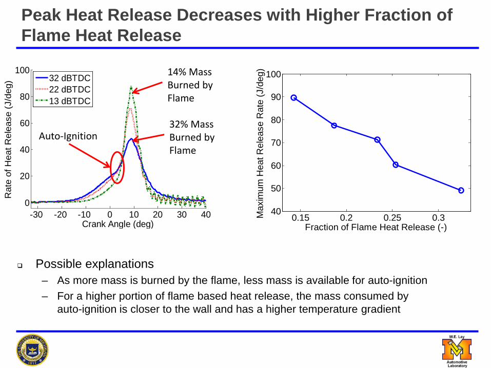
Possible explanations – As more mass is burned by the flame, less mass is available for auto-ignition – For a higher portion of flame based heat release, the mass consumed by
auto-ignition is closer to the wall and has a higher temperature gradient
Peak Heat Release Decreases with Higher Fraction of Flame Heat Release
0.15 0.2 0.25 0.340
50
60
70
80
90
100
Fraction of Flame Heat Release (-)
Max
imum
Hea
t Rel
ease
Rat
e (J
/deg
)
-30 -20 -10 0 10 20 30 400
20
40
60
80
100
Crank Angle (deg)
Rat
e of
Hea
t Rel
ease
(J/d
eg) 32 dBTDC
22 dBTDC13 dBTDC
32% Mass Burned by Flame
14% Mass Burned by Flame
Auto-Ignition

Operational Constraints
-30 -25 -20 -151
1.5
2
2.5
3
3.5
Spark Advance (dATDC)
CO
V of
IMEP
n (%
)
-30 -25 -20 -151
2
3
4
5
6
7
8
Spark Advance (dATDC)
Rin
ging
Inte
nsity
(MW
/m2 )
-30 -25 -20 -151.5
1.75
2
2.25
2.5
Spark Advance (dATDC)
EI-N
Ox
(g/k
g fu
el)
As spark is advanced: – More mass is consumed by the flame – Less mass auto-ignites simultaneously – Trends are opposite of what advancing
spark alone gives – Ringing intensity and NOx decreases – COV of IMEPn increases
– Caused by flame or auto-ignition?
Ringing Intensity (MW/m2)
COV of IMEPn (%)
EI-NOx (g/kg fuel)

Effect on Thermal Efficiency
Thermal efficiency remains relatively constant despite changes in compression temperature and burn rate
At constant load, we can manipulate the combustion behavior (to reduce NOx and ringing) without negatively affecting thermal efficiency
-30 -25 -20 -150.3
0.35
0.4
0.45
0.5
Spark Advance (dBTDC)
Ther
mal
Effi
cien
cy (-
)
NetGross

Thermodynamic and drive cycle simulations indicate that significant improvements in IC engine brake thermal efficiency can be made relative to conventional powertrains with downsized boosted combustion – Additional gains can be made by operation within the advanced
combustion regime (HCCI + SACI combustion modes) – Additional measures will be required to meet future CAFE
regulations – 54.5 mpg
SACI combustion is one means of accessing the advanced combustion regime – This has been demonstrated for naturally aspirated operation – Future work will ideally focus on boosted, SACI combustion
Conclusions and Future Work

Thanks to George Lavoie, Dennis Assanis, Aris Babajimopolous and graduate students Laura Manofsky and Elliott Ortiz-Soto
Department of Energy Contract DE-EE0000203, A University Consortium on Efficient and Clean High Pressure Lean Burn (HPLB) Engines
Acknowledgements


Timing and Burn Duration Effects
For reasonable burn durations, CA50 is more important to gross efficiency than burn duration
Unfortunately, brake efficiency does not scale with gross efficiency trends – FMEP (speed) – nearly constant in
these plots – Relative friction becomes much more
important at low load • This causes the departure between
gross and brake efficiencies and is a problem with low load operation
Lavoie, G. A., Ortiz-Soto, E., Babajimopoulos, A., Martz, J., Assanis, D.N. (2012) Thermodynamic sweet spot for high efficiency, dilute boosted gasoline engine operation, in press Int. J. Engine Res.

The Effect of Gamma
Gross efficiency improves with dilution – Low burned gas
temperatures lead to higher gamma

Air vs. EGR Dilution