advanced computer graphics - rendering
TRANSCRIPT


February 5, 2015 [email protected] 2
The computer screen is a flat surface. When image data is stored in the
computer it is in the form of a data structure consisting of coordinate
points. a data structure of image points cannot be displayed directly onto
a flat computer screen.
In the same way that an engineer must use a rendering scheme in order
to represent a solid object onto the surface of the drawing paper, the
programmer must find a way of converting a data structure of coordinates
into an image on the computer monitor.
Introduction

February 5, 2015 3 [email protected]
generating 2D images of a 3D world represented in a computer, building 2D images from 3D models ,Rendering is the conversion of a
scene into an image:
Scenes are composed of models in three-dimensional space, Models
are composed of primitives supported by the rendering system, Models
entered by hand or created by a program, The image is drawn on
monitor, printed on laser printer, or written to a raster in memory or a
file.
Rendering

February 5, 2015 [email protected] 4
Classically, "model" to “scene" to “image" conversion broken into finer
steps, called the graphics pipeline. The basic forward projection
pipeline looks like:
Rendering

February 5, 2015 [email protected] 5
Each stage refines the scene, converting primitives in modeling space to
primitives in device space, where they are converted to pixels
(rasterized).
Rendering

February 5, 2015 [email protected] 6
Three conceptual stages of the pipeline:
– Application (executed on the CPU)
– Geometry
– Rasterizer
Rendering Pipeline

February 5, 2015 [email protected] 7
The APPLICATION stage
Executed on the CPU, Means that the programmer decides what
happens
Most important task: send rendering primitives (e.g. triangles) to the
graphics hardware
The GEOMETRY stage
”geometrical” operations on the input data (e.g. triangles)
Allows:
– Move objects (matrix multiplication)
– Move the camera (matrix multiplication)
– Compute lighting at vertices of triangle
– Project onto screen (3D to 2D)
– Clipping (avoid triangles outside screen)
•Map to window
Rendering Pipeline

February 5, 2015 [email protected] 8
The RASTERIZER stage
Main task: take output from GEOMETRY and turn into visible pixels
on screen
Also, add textures and various other per-pixel operations
Rendering Pipeline


February 5, 2015 [email protected] 13
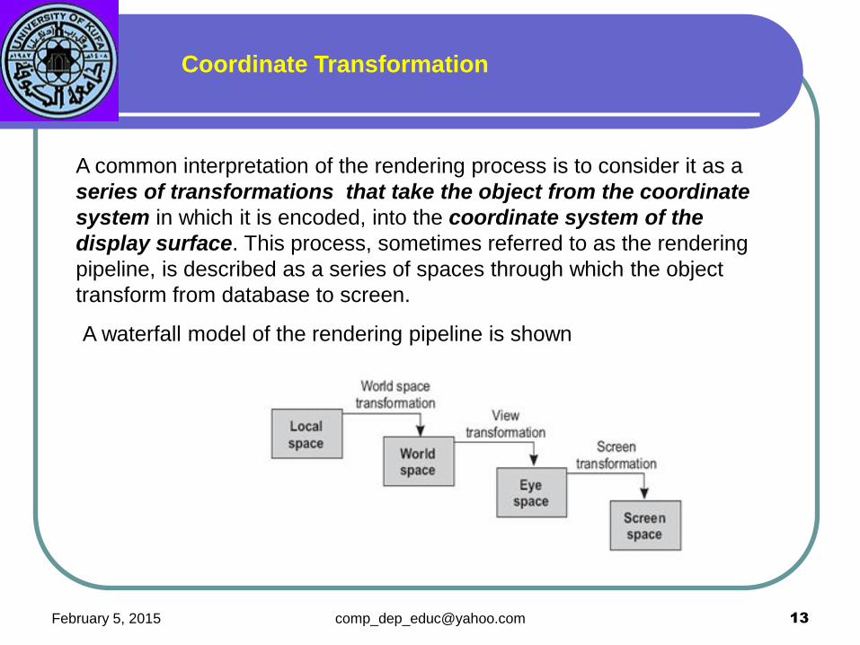
A common interpretation of the rendering process is to consider it as a
series of transformations that take the object from the coordinate
system in which it is encoded, into the coordinate system of the
display surface. This process, sometimes referred to as the rendering
pipeline, is described as a series of spaces through which the object
transform from database to screen.
A waterfall model of the rendering pipeline is shown
Coordinate Transformation

February 5, 2015 [email protected] 14
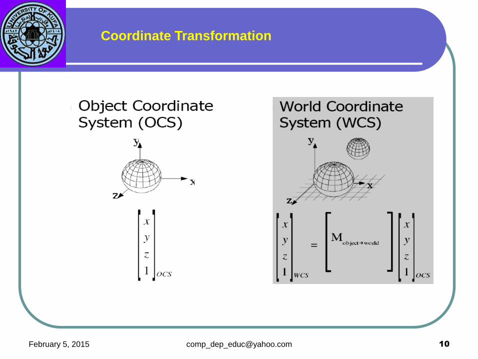
Local Space
Objects are usually easier to model if they are conveniently positioned in the
coordinate plane. For example, when we place the bottom-left vertex of a
cube at the origin of the coordinate system, the coordinates are all positive
values
Coordinate Transformation

February 5, 2015 [email protected] 15
World Space
The coordinate system of the scene is called the world space, or world
coordinate system.
Objects modeled in local space usually have to be transformed into
world space at the time they are placed in a scene. For example, a
particular scene may require a cube placed so that its left-bottom vertex
is at coordinates x = 2, y = 3, z = 0. The process requires applying a
translation transformation to the cube as it was originally defined in local
space. Furthermore, lighting conditions are usually defined in world
space. Once the light sources are specified and located, then shading
and other rendering transformations can be applied to the polygons so
as to determine how the object appears under the current illumination.
Surface attributes of the object, such as texture and color, may affect
the shading process. Figure shows the world space transformation of a
cube under unspecified illumination conditions and with undefined texture
and color attributes.


February 5, 2015 [email protected] 17
A vector space is a mathematical structure that
is defined by a given number of linearly
independent vectors, also called base vectors
(for example in Figure, there are three base
vectors);
Every model in the game lives in its own Model
Space and if you want them to be in any spatial
relation (like if you want to put a teapot over a
table) you need to transform them into a
common space (which is what is often called
World Space).
Coordinate Transformation

February 5, 2015 [email protected] 18
Now let's say that we start with an active space, call it Space A, that
contains a teapot. We now want to apply a transformation that moves
everything in Space A into a new position; but if we move Space A we then
need to define a new "active" space to represent the transformed Space
A. Let's call the new active space Space B
Coordinate Transformation

February 5, 2015 [email protected] 19
The first step when we want to render a 3D scene is to put all the models
in the same space, the World Space. Since every object will be in its own
position and orientation in the world, every one has a different Model to
World transformation matrix.
Three teapots each one in its own model space
Coordinate Transformation

February 5, 2015 [email protected] 21
With all the objects at the right place we now need to project them to
the screen. This is usually done in two steps. The first step moves all the
object in another space called the View Space. The second step performs
the actual projection using the projection matrix. This last step is a bit
different from the others and we will see it in detail in a moment.
Why do we need a View Space? The View Space is an auxiliary
space that we use to simplify the math and keep everything elegant and
encoded into matrices. The idea is that we need to render to a camera,
which implies projecting all the vertices onto the camera screen that can
be arbitrarily oriented in space.
Coordinate Transformation

February 5, 2015 [email protected] 22
Now, if you imagine you want to put the camera in World Space you would use
a transformation matrix that is located where the camera is and is oriented so
that the Z axis is looking to the camera target.
two teapots and a camera in
World Space
everything is transformed into View
Space (World Space is represented
only to help visualize the
transformation)
Coordinate Transformation

February 5, 2015 [email protected] 23
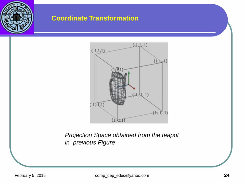
The scene is now in the most friendly space possible for a projection, the
View Space. All we have to do now is to project it onto the imaginary screen
of the camera. Before flattening the image, we still have to move into
another, final space, the Projection Space. This space is a cuboid which
dimensions are between -1 and 1 for every axis. This space is very handy
for clipping (anything outside the 1:-1 range is outside the camera view
area) and simplifies the flattening operation (we just need to drop the z
value to get a flat image).
Coordinate Transformation
February 5, 2015 [email protected] 24
Projection Space obtained from the teapot
in previous Figure
Coordinate Transformation
February 5, 2015 [email protected] 25
Eye Space
The eye space, or camera coordinate system, introduces the
necessary transformations to improve rendering to any desired
degree. Perspective transformations requires knowledge of the
camera position and the projection plane.
Backface Elimination or Culling
One of the most important rendering problems that must be solved at
this stage of the pipeline is the elimination of the polygonal faces
that are not visible from the eye position, In the simplest case,
entire polygons that are not visible are removed at this time.
This operation is known as culling.

February 5, 2015 [email protected] 26
A solid object composed of polygonal surfaces that completely enclose
its volume is called a polyhedron. the polygons whose normals point
away from the eye or camera can be assumed to be blocked by other,
closer polygons, and are thus invisible.
A single mathematical test can be used to determine if a polygonal face
is visible.
The geometric normal to the polygonal face is compared with a vector
from the polygon to the camera or eye position. This is called the line-of-
sight vector. If the resulting angle is greater than 90 degrees, then the
polygonal surface faces away from the camera and can be culled. Figure
shows the use of polygonal surface and line-of-sight vectors in culling.

February 5, 2015 [email protected] 27
Once the position of the camera
is determined in the scene, it is
possible to perform the backface
elimination.

February 5, 2015 [email protected] 28
February 5, 2015 [email protected] 29
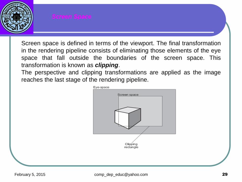
Screen space is defined in terms of the viewport. The final transformation
in the rendering pipeline consists of eliminating those elements of the eye
space that fall outside the boundaries of the screen space. This
transformation is known as clipping.
The perspective and clipping transformations are applied as the image
reaches the last stage of the rendering pipeline.
Screen Space

February 5, 2015 [email protected] 30
Types of rendering
a. Wireframe
b. Smooth shading
c. Ray tracing
d. Radiosity

February 5, 2015 31 [email protected]