advanced general aviation propeller … summary 1 introduction 3 symbols 5 technology development 7...
TRANSCRIPT

CONTRACT REPORTNASACR 114399
ADVANCED GENERAL AVIATIONPROPELLER STUDY
(I_sA-CN 11tt]qql,)£tlD¥ _'DvANCE_ GEt_I_L AVIfiT£ON. , ,_'tal !
pROPELLF,_ Bt_nd4rd )R" ;_orobel
_(Hamilton 21 Dec. 1971 5L_ p _-G3/02 Ut,claS184560,,/" ,_CSCL 01C --------_HCU_
a 3_OK tl
: B ¥ROSE WOR OBEL _ _:_;' ',_"---0_''_::_'
• .,, .., _;7'/__',-7) ,_,,,
DECEMBER 21,1971 \,:'.',, ,,,'.."_"'d f "h_'• _.__ ""."'
PREPARED UNDER CONTRAC.T NO. NAS2--6477 BYHAM ILTON STANDARDDIVISION OF UNITED AIRCRAFT CORPORATION
;, WINDSOR LOCKS ,CONNECTICUTFOR
i' ' _ ADVANCED CONCEPTS AND MISSIONS DIVISION' OFFICE OF ADVANCED RESEARCH AND TECHNOLOGY
NATIONAL AERONAUTICS AND SPACE ADMINISTRATION
" -_"f_ "-"-_'_':';"_ "_ ° ........... --_ ...... 1972010354
https://ntrs.nasa.gov/search.jsp?R=19720010354 2018-06-08T23:04:59+00:00Z

_
CONTRACT REPORTNASA CR 114399
ADVANCED GENERAL AVIATION PROPELLER STUDY
ByRose Worobel
MiUard G. MayoDecember 21, 1971
'_" Prepared Under Contract No. NAS2-6477 By
:'._' HAMILTON STANDARD
' Division of United Aircraft CorporationWindsor Locks, Connecticut
i"
for
ADVANCED CONCEPTS AND MISSIONS DIVISION
OFFICE OF ADVANCED RESEARCH AND TECHNOLOGY
NATIONAL AERONAUTICS AND SPACE ADMINISTRATIONq
• rJ
,l f_ f,.. I A(,I,, ,lH,A_',,q( NOT i |I_Mr,D
ABSTRACT
Under a previous NASA contract and reported in CR-114289 methods for pre-dicting the performance, noise, weight, and cost of propellers for advanced genera[aviation aircraft of the 1980 time period were developed and computerized. Underthe present contract this baste program was refined to incorporate a method of includ-
ing the blade shape parameter, integrated design lift eoefficl_:nt, This method arLda
reverse thrust computational procedure were included in the computer program. Thewetg_ equation was refined and also incorporated in the computer program. A Userts
Manual which includes a complete listing of this computer program with detailedinstructions on tt_ use has been written and will be published as a NASA low number
Contractor RoporL
Ill/iv
" 1972010354-TSA04

CONTENTS
, SUMMARY 1
INTRODUCTION 3
SYMBOLS 5
TECHNOLOGY DEVELOPMENT 7
Method for Varying Integ:ated Design Lift Coefficient, 7Integrated Design Lift Coefficient Adjustment Factor, 9Compressibility Factor 10
Method for Computing Reverse Thrust 11Computational Procedure 13
Refinement of Weight Generalization 16
Input/Output Additions to the Computer Program 17
USERtS MANUAL 19
._' CONC LUDING REMARKS 21
REFERENCES 23
,..;._ TABLES_..
:' I Weight Summary of Propellers Studies for 1980 25
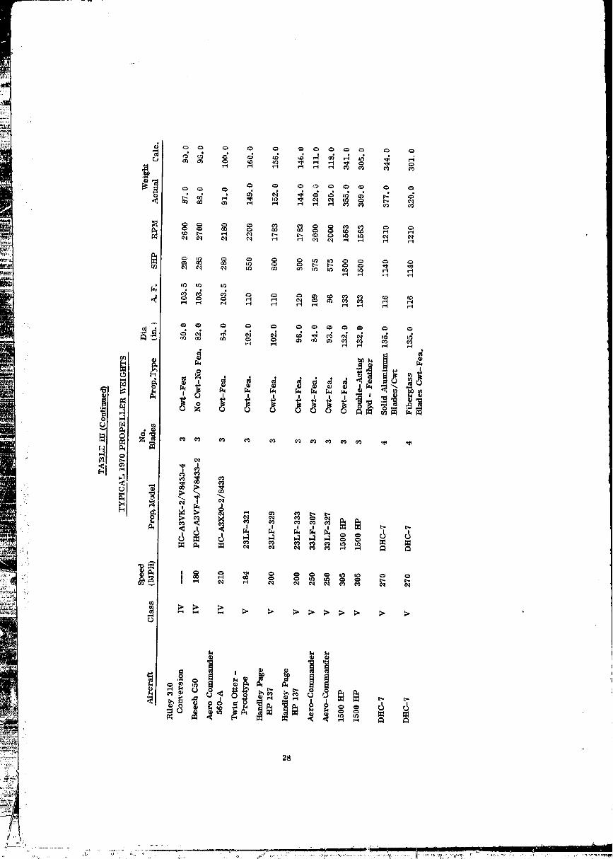
.... II General Aviation - Generalized Propeller Weight Equation 26!_:_._i III Typical 1970 Propeller Weights 27
:." IV O.E.M. Single Unit Cost Summary of Representative
i.i_ii,i Propellers for 1980 29
.:: FIGURES
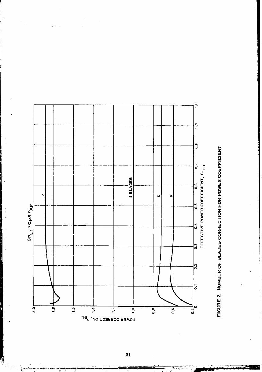
1 Blade Camber Distribution 302 Number of Blades Correction for Power Coefficient 313 Camber Factor Adjustment for Advance Ratio 324 Integrated Design Lift Coefficient Adjustment to Power
Coefficient for 4-Bladed Propellers 335 Number of Blades Correction for Thrust Coefficient 34
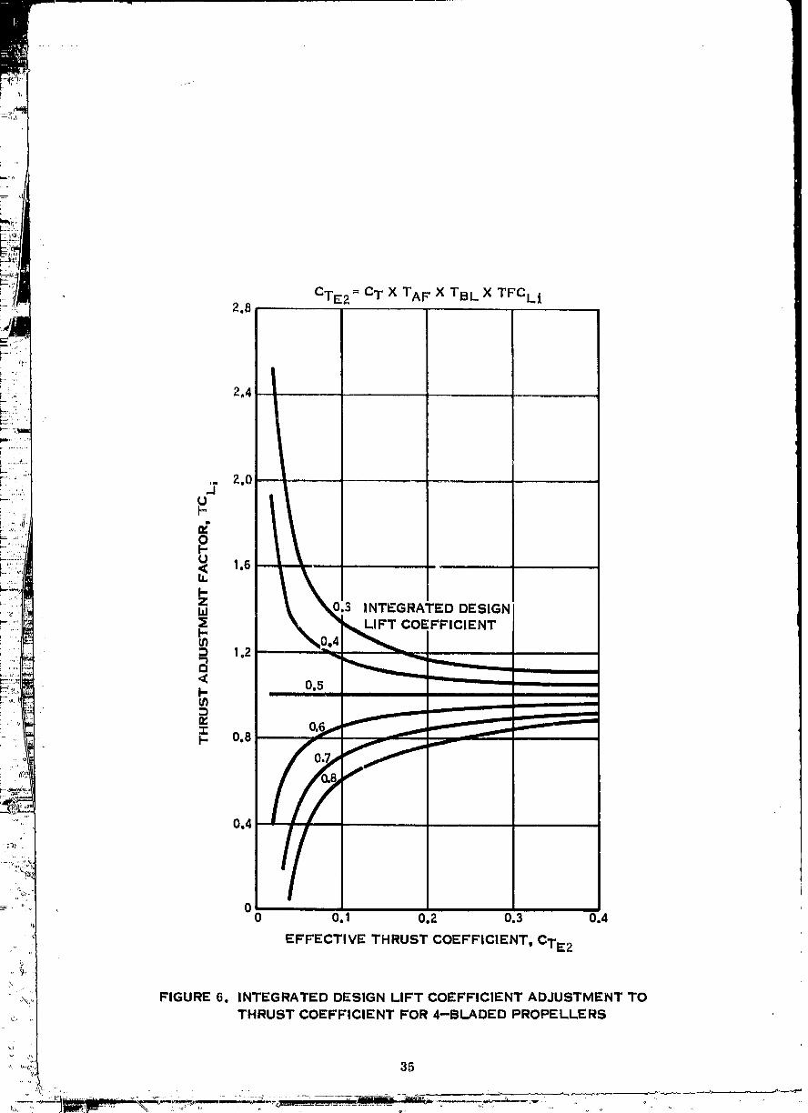
• 6 Integrated Design Lift Coefficient Adjustment to ThrustCoefficient for 4-Bladed Propellers 38
.: 7 Critical Mach Number for Advance Ratios Greater than Zero 36
V
1972010354-TSA05

i
CONTENTS (Continued)
FIGURES (Continued)
8 C ritical Mash Number for Advance Ratios Equal to Zero 379 Compres_ibility Adjustment 38
10 E_cample Reverse Thrust Variation w_th Landing Speed and Power Setting 3911 Activity Factor Adjustment to Torque Coefficient 40
12 Integrsted Design Lift Coefficient Adjustment to Torque ,.C o_Jffleient 41
13 Variation of Percentage of Integrated Design Lift CoefficientCorrection Required for Thrust and Torque 42
14 Basic Performance Curve - Variation of Effective TorqueCoefficient with Advance Ratio and Blade Angle 43
15 Integrated Design lift Coefficient Adjustment to TorqueCoefficient 44
16 Basic Performance Cur_e - Variation of Effective Thrust
Coefficient with Advance Ratio and Blade Anglo 4517 Activity Factor Adjustment to Thrust Coefficient 4G
18 Integrated Design Lift Coefficient Adjustment to Thrust
Coeffieient 47 !19 Sample Case I of Computer Program Output 4820 Sample Case II of Computer Program Output 49

SUMMARY
A major outcome of the study sponsored by the Advanced Concept and mission. Division, A. C.M.D. of NASA under Contract No. NAS2_5885 dated 30 January 1970
and reported in CR 114289 has been the developnmnt of a computer program for evalu-ating propeller performance, noise, weight and cost for general aviation aircraft pro-
pollers as a function of the primo geometric and aerodynamic variables. This programprovides for changes in the activity factor per blade and number of blades, but it waslimited to a single value of integrated design lift coefficient. This study, Contract No.NAS2-6477 dated fl May 1971 and also sponsored by the A. C. M. D., extends this com-puter program to incorporate the integrated deMgn lift coefficient as a propeller bladeshape variable. Additional extensions to the computer program which are documentedin this report are the eapabiliW of calculating propeller reverse thrust and the refine--meat of the propeller weight equation. A final requirement of Contract No. NAS2-6477was to describe the complete computer program. This manuM is reported in a sep-arate low number NASA Contractor Report.
In this report the technology is developed for including the capability of varyingintegrated design lift coefficient. An existing reverse thrust method has been adaptedfor the general aviation aircraft application. The weights for 36 additional propellersover those used in the original study have been defined analytically and used in refiningthe weight equation. These technology additions and revisions are incorporated into the
: computer program.
1/2
.... TSA07' 1972010354-

INTRODUCTION
Aviation forecasts for the next ten to fifteen year time period, indicate the eon- if
tinned steady growth of general aviation. Furthermore, it is apparent that most of [
these aircraft, even into the 1980 time period will be propeller driven utilizing prima- Irily reeiproeating engines with turbine engines coming on as their economies improve.The attainment of this forecasted growth is dependent upon the eontl 1ned improvement 1in the safety, utility, performance and cost of general aviation sire" ,fit. I
|
In view of this, a study was undertaken under NASA sponsorship to derive and 1computeriz_ appropriate propeller performance, noise, weight and cost criteria to
permit sensitivity studies of these factors to be made for adwmee propeller configura-tions designe_ for general aviation aircraft of the 1980 time period. The results ofthis study wer,_ presented in Contractor Report NASA Cfl 114289, "Advanced General
Aviation Stud:¢ ,t April 1971 (rof. 1). At NA_AIs request a contract study was under-" taken to provide a Userts Manned which includes a complete listing of this compt_¢er
program with detailed instructions on its use. Furthermore the scope of the computerprogram has been extended to incorporate the following:
1. Method for varying integrated design lift coefficient (the only primeblade shape variable not included in the original program)
_. 2. Method for computing reverse thrust
: 3. Refinement of the weight equation
Thus a reliable computer program has been developed for predicting propeller perfor-mance (static, flight and reverse), noise, weight and cost for the complete general
:i_ aviation aircraft range.i .
'_' A detailed discussion of the technology developments and incorporation into the.:_ computational procedures of the above extensions to the computer program are discussed
in the following text. The Userts Manual which includes FORTRAN IV listings andInput/output Instructions wtll be published under separate cover as a NASA low numberContractor Report.
3/4
1972010354-TSA08
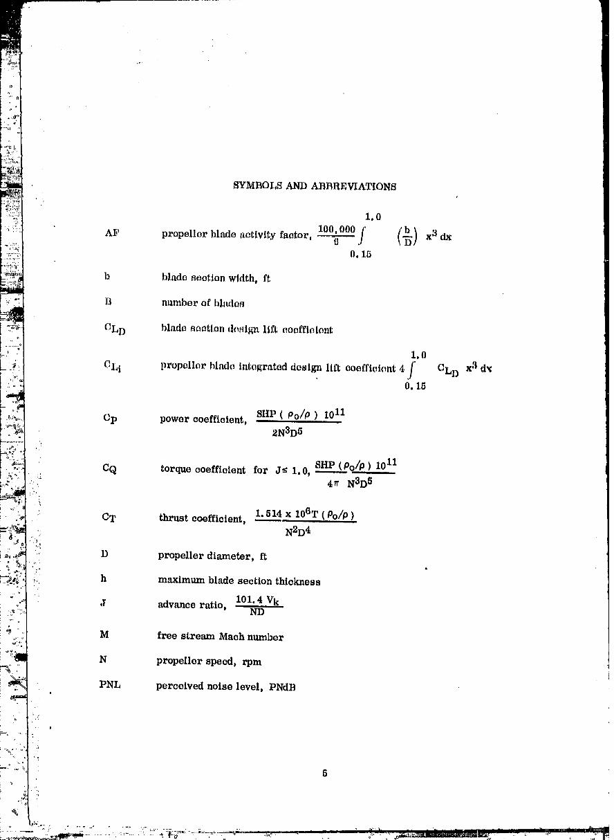
SYMBOLS AND ABBREVIATIONS
i.0
O.15
b blade aaetion width, ft
B ntmlber of bladefl
CLD blade B_ctlon design lift coefficient
1.0
ELI propeller blnde integrated destine Ill% coefficient 4 f CLD x3 d,_0.18
SHP(Po/P) I0IICp power coefficient,
2N3D 5
CQ torque coefficient for J_ 1.0, SHP (____._Po/P).101147r N3D 5
1.514x 10⁶T..(Po/p)CT thrust coefficient,N2D 4
D propeller diameter, ft
h maximum blade section thickness
101.4 VkJ advance ratio, ND
M free stream Mach number
N propeller speed, rpm
PNL perceived noise level, PNdB
5
..........,............ ,.......;>.,_
...."_"='_ ........."".............."_ ' " 1972010354-T 9

Qc torque coefficient for J;. 1.0, SHP(Po/P) 1011 I4_r N3D 5 j2
'i
R blade radius at propeller tip, ft
r radius at blade element, ft
SHP _haft horsepower
T propeller thrust, pound_
TC thrust coefficient for J_ 1.0, 1._14 x 106 T(Po/p ) X 1N2D4 j2
VK freostrc_un velocity, lmots
x fraction of propeller tip r_lius, r/R
_3/4 propeller blade angle at 3/4 radius
P density, lb sec2/ft 4
Pc density at sea level standard day, 0.002378 lb. scc2/ft 4
_,:. %lp 01_
0 ratio of absolute temperature to absolute _emperature at sea level,
•_' T/To?
. 'i _ ratio of static pressure to static pressure at sea level, P/Po
:/i::_!i.='
' 6
' °- '....... ' ° " __" _ _ - 1972010354-TSA10

TECliNOLOGY DEVELOPMENT
Method for Varying Integrated Design Lift Caeffiaient
In the original report (ref. 1), a perfornianee method generalization was devel_.oped far predicting static and forward flight performance for general aviation aircraftpropellers. The horsepower, thrust, propeller rotational spe_d, velocity and dia_motor are included In the non-dimensional farm of power coefficient, Cp, thrustaocffieiont, CT, and advance ratio, J defined as fallows:
fdliP ( Po/P ) 10J]Cp _ ....
2N3D 8
1.514.x i06T (Oo/p )('T _-_ ....
N2D d
101.4 VKJ = ' ND
where:
SlIP - shaft horsepower
Po/P - ratio of density at sea level standard day to density' for a specific operating condition
_,, N - propeller speed, rpm
,, D - propeller diameter_ft
T - propeUer thrust, pounds
VK - forward speed velocity, knots
Base curves were defined in this non-dimensional form presenting the perfor-mance of 2, 4, 6 and 8 bladed propellers referenced to an activity factor of 150 and0.5 integrated design lift coefficient.
. In order to minimize the number of curves and consequently the size and complex-
ity of the computer program, the terms effective power coefficient, CPE, and effective: thrust coefficient, CTE were introduced. The effective power coefficient and thrust
7
..... .. 1972010354_TSA11

CTE _ C TxTAFxTCLI
where=
Cp .- pawar aoeffietent
PAF - nativity factor luiJustmt_nt to power eoofflalont (rof. 1, fig 3A)
PCL l - integrated design lift coefficient, eLl ralJtmtmont fimtor to l)oweraoeffiatont (do_ot_llmd in subt_oquoat text)
(2T -- thru._t aooffiektnt
TAF - activity fatJtor adjustment factor to thrust t,)offtcl_a_ (rift. 1,fig. 3A)
TCL l - integrated design lift coefficient,eL i adjustment factor to thrust'.'i coefficient (described in subsequent text)
I
In the original report, the base performance curves and the activity factor
i ,_ adjustment factors, PAF and TAF were developed and included in the computer pro-,, gram. Furthermore, a limited anmunt of work was done to establish the feasibility
• of gener_izing the integrated design li.ft coefficient effect. Under the present studycontract, the integrated design lift coefficient adjustment factor was developed for a
. '_ range of 0.3 _ CLt _ 0.8. Blade camber distributions for this range of CL! are shown: '_'i: in figure 1. Thus, the base curves while referenced to a basic activity factbr and
.::, integrated design lift coefficient, are applicable to the complete range of 2 to 8 blades,
80-200 activity factor and O. 3 to O. 8 integrated design lift coefficient.
Since it has been projected tha_ general aviation aircraft will be operating atsignificantly ,higher speeds by the 1980 _tme period, a compressibility factor, Ft forthe base curves of 0.5 integrated design lift coefficient was derived for use with thebase plots presented in reference 1. The thrust is multiplied by the Ft to correct forcompressibility losses. Under the present contract, the Ft correction was expandedto apply to the complete range of integrated design lift coefficient of 0. -_to 0.8.
The development of the integrated design lift coefficient adjustment factors,
: PCLt and TCL t and the compressibility correction, Ft, as well as their incorporation
"' ' L/., 8
into the computational procedures are described in the following text
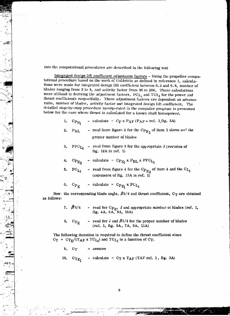
Integrated design lift coefficient adiustmen_ factors - Using the propeller compu-tational procedure based on the work of Goldstein _ defined in reference 1, calcula-tions were made for integrated design lift coefficient between 0.3 and 0.8, number ofblades ranging from 2 to 8, and activity factor from 80 to 200. These calculations
were utilized in deriving the adjustment factors, PCLz and TCL l for the power ,_Aldthrust coefficients respectfully. These adjustment factors are dependent on advanceratio, number of blades, activity factor :rod integrated design lift coefficient. The
detailed step-by-step procedure incorp_,rated in the computer program is presented
below for the ease where thrust is calculated for a known shaft horsepower.
1. CPE 1 - ealetflate = Cp x PAF (PAF- ref. 1,fig. 3A)
2. PBL - read [_om figure 2 for the CPE 1 of item I above an,! the
proper number of blades
3. PFCLi - read from fig_tre 3 for the appropriate J (revision offig. 12A in ref° 1)
4. CPE2 - calculate = CPE 1 x PBL x PFCLI
5. PCLI - read from figure 4 for the CPE 2 of item 4 and the CLi(expansion of fig. 13A in ref. 1)
6. CPE - calculate = CPE 1 x PCLi
Now, the corresponding blade angle, _3/4 and thrust coefficient, C T are obtainedas foUows:
,i_; °j 7. _3/4 - read for CPE , J and appropriate number oi blades (ref. 1,_:?_ fig. 4A, 6A, 8A, 10A),,1
_:_ °J 8. - read for J and fl3/4 for the proper number of blades_ _ (ref. 1, fig. 5A_ 7A, 9A, llA)_, CTE
The following iteration is required to define the thrust coefficient since
,, C T = CTE/(TAF x TCLi) and TCLi is a function of CT.
_o 9. C T - assume4_mrv),-,
10. CTE 1 - calculate = CT x TAF (TAF ref. 1, fig. 3A)
- •
Li 9
,.i__o
1972010354-TSC01
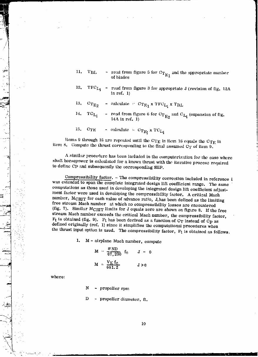
11. TBL - read from figure 5 for CTE 1 and the appropriate numberof blades
,. 12. TFCLi - r,_ad from figure 3 for appropriate J (revision of fig. 12Ain ref. 1)
1, - calculate x TFCLI x13. C I_E2 = CTE1 TBL
14. TCLI _ read from figure 6 for CTE 2 and CLI (expansion of fig.14A in ref. 1)
15, CTE - calculate= CTE I x TCLi
Items 9 through 15 are repeated until the CTE in item 16 equals the CTE initem 8. Compute the thrust corresponding to the final assumed CT of item 9.
A similar procedure has been included in the computerization for the case whereshaft horsepower is calculated for a known thrust with the lterative proeesg required
to define CP and subsequently the corresponding SLIP,
Compressibility factor. - The compressibility correction included in reference 1was extendedto span thecomplete integrateddesig_ liftcoefficientrange. The same
computationsas those used indevelopingthe integrateddesign liftcoefficientadjust-
..... ment factor were used in developing the compressibility factor. A critioal Machnumber, MCRIT for each value of advance ratl.o, J, has been defined as the limitingfree stream Mach number at which no compressibility losses are encountered
• • (fig. 7). Similar MCRI T limits :for J equals zero are shown on figl_re 8. If the free::: stream Mach number exceeds the critical Maeh number, the compressibility factor,
: F t is obtained (fig. 9). Ft has been derived as a function of CT instead of Cp asdefined originally (ref. 1) since it simplifies the computational procedures when
, ,': .'
the thrust input option is used. The compressibility factor, Ft is obtained as follows.
::::!:'::i.: 1. M- airplane Mach number, compute• -! •
: 7r NDM - fc J = 0
' .. 67,200
M - VK fc J >0661.2
where:
N - propeller rpm
" D - propeller diameter, ft.
•" 10
1972010354-TSC02
fc - ratio of speed of sound at standard day sea level to speed ofsound at operating condition
VK - free stream velocity, knots true airspeed
2. MCRIT - read from figure7 forJ >0 and figure 8 for J=0
for CLI (expansion of fig, 15A in ref. 1)
3. A(M_McRIT ) - calculate where M is the free _tream Much number
4. CTE 3 - calculate = CT x TAF x TBL x TCLI
5, F t - read from fig_are 9 for CTE3 and A (M-McI_IT)
Method for Computing Reverse Thrust
Aircraft incorporating propellers with the reverse thrust feature have the capa-bility to limit the _anding ground run to significantly shorter distances than with _heelbrakes alone. The propeller normally operates at a fixed reverse blade angle setting
: throughout the ground run operation and the reverse angle is selected to absorb normalrated power and speed at zero velocity. Occasionally, the reverse blade angle setting
,:,. is based on a partial throttle setting instead of full throttle. Therefore, the option.of computing reverse angle and the corresponding reverse thrust, horsepower andpropeller speed for a range of velocities spanning the ground run speeds based on
'_ operating at several throttle settings is included in the computer program. With this"'. ,T
.:, data (fig. 10), the corresponding landing distances can be computed and accordingly
: . the appropriate reverse angle and power setting can be obtained.
• .: The analytical method for computing reverse thrust is based on an existing
Hamilton Standard procedure which was obtained by generalizing all available propeller...'
., test data. The shaft horsepower, thrust, propeller rotational speed, velocity and
' diameter are included in the non-dimensional form of torque coefficient, CQ or QC,_. thrust coefficient, CT or TC, and advance ratio, J defined as follows:
j = !01.4 VKND
SHP ( Po/P ) 1011 for J _ 1.0CQ =.
41r N3D 5
• 11
1972010354-TSC03

11
Qc Slip ( Po/P ) 10 1= x -- for J>l.04v N3D 5 j2
1.514x10⁶ T (Po/P)C T ..... for J_ 1.0
N2D 4
1T C = -I'B14xl06T(p°/P). x --- forJ>l.0
N2D 4 j2
where:
SHP - shaft horsepower
Po/P - ratio of density at sea level standard day to density for a specificoperating condition
N - prdpei.ler speed., rpm
D - propeller diameter, ft
T - propeller thrust, pounds
:, VK - forward speed velocity, knots
Base curves have been defined in this manner for a 3 bladed, 100 activity factor,
:: 0.4 integrated design lift coefficient propeller. The terms effective torque coefficient,:_. CQE or QCE, and effective thrust coefficient, CTE or TCE, are used. As with the
"., forward flight generalization, these base curves with appropriate adjustments for AF,... CL i and number of blades can be used in predicting reverse thrust characteristics
.. for the family of propellers spanning 2 to 8 number of blades, 80-200 AF, and 0.3 to
• 0.8 CLi. The effective torque coefficients and thrust coefficients are defined as follows:
CQE=
..... QCE = [Qc x (3/B) 0o 83 x QAFJ - AQCE2 (PCR/100) for J • 1° 0
CTE = [C T x (3/B) 0. 83 x TAF1 - ACTE 2 (PCR/100) for J _ 1.0
TC E = IT c X(3/B)0.83 x TAF ] - ATCE 2 (PCR/100) for J • 1.0
12
where:
!: CQ - torque coefficient for J _ 1.0
(3/B)0.83 - number of blades, B,adjustment
QAF - activity factor adjustment factor to torque (fig. 11)
ACQE 2 - integrated design lift coefficient adjustment factor totorque for J < 1.0 (fig. 12)
PCR - percentage of integrated design lift coefficient adJuntmentfactor to use (fig. ].3)
QC - torque coefficient for J _- 1.0
The base torque perfornmnce curves are shown on figure 14.
AQCE 2 - integrated design lift coefficient adjustment factor totorque for J > 1.0 (fig. 15)
CT - thrust coefficient for J _ 1.0i:i:• _ The base thrust performance curve is shown on figure 16.
' .. TAF - activity factor adjustment factor to thrust (fig. 17)
: ACTE 2 - integrated design lift coefficient adjustment factor to: thrust for J_ 1.0 (fig. 18)
: ::_:'i! T C - thrust coefficient for J > 1.0
i: .... ATCE2 - integrated design lift coefficient adjust_c_lt factor to• thrust for J > 1.0 (fig. 18)
Computational procedure. - Using the method described above, the reverse angleis computed for zero velocity and a SHP and RPM corresponding to a specific throttlesetting and the pressure and temperature condition associated with the airport. Withthe angle so defined, the SHP and RPM and the corresponding reverse thrusts arecomputed for the range of ground run velocities. It is reasonable to assume that
for reciprocating engine installations SHP/N remains constant throughout the completereverse range and that for power turbine installations, SBP remains constant for theturbine speed range encountered during landing.
:i
13
1972010354-TSC05
For each throttle setting at zero velocity the following calculations are made tocompute the corresponding reverse angle.
• .. 1. CQ - oalculate for given SHP and RPM
2. QAF - read from figure 11 for the specified AF and CLI
3. (3/B)0.83 .- number of blades, B adjustment, computed
4. ACQE 2 - read from figure 12 for J=0 and specified CLI
5. PCR - 100 for J = 0
6. CQE - calculate ((2Q x QAF x (3/B) 0" 83) _ ACQE 2 x (PCR/100)
7. _3/4 - read from figure 14 for CQE and J -_ 0
For a range of J's the fol.lowing calculations are made to define the RPM and
power relationships over the landing run range.
8. J - advance ratio, assume a range of JTs
9. CQE or - IfJ$1.0, read CQEIOr J(Item 8) and reverse
'_' QCE 133/4 (item 7) and if J >1.0, QCE from figure 14•i_
/:-i '__ 10. ACQE 2 or - if J _ 1.0, read ACQE 2 frcm figure 12 or AQCE 2 from• . AQCE 2 figure 15 if J >1.0 for CLi and J
: 11. PCR - read from figure 13for f_3/4andJ_0.9; for J>0.9,.... •
..,_ PCR = 0
:: : _i•i_
: :<'.;.:.:, 12. CQ - calculate where
.+. CQE +-: :_:i_ CQ = - ACQE _ x (PCR/100) for J _ 1.0! ' QAF x (3/B) 0. 83
notingthat CQ = QC x j2
CQ = (QCE+AQCE2X (PCR/100) forJ>l. 0• ,,, 'ii QAF x (3/B) 0. 83
c)_) ,
14
...._._.............. : . . _ . .... _, - - , :.-_ _._" " _'_.!_ _:-'-_ _: ' _'-_
,._i..... " " - Y ...._'_',:_-_?:.....................:'"!_"_""_ "" '_........................... "19720"I0354-T8006

For turbine engine installations, go to item 15. For aircraft with reciprocatingengines, SHP/N remains approximately constant throughout the complete reversingcange. Therefore,
13. N - propeller rpm is calculated = RPM 1 /C_O-_1/2
where subscription 1 refers to item land subscript2 to item 12
SHP1 x RPM214. flHP - calculate -RPM 1
where subscript 1 refers to item 1 m_d subscript 2to item 1:]. Go to item 17.
For aircraft with turbine engines, SlIP remains approximately constant and thereibre
Nwhere the subscript 1 refers to item 1 and subscript2 refers to item 12
.:_. 16. SHP - same as used in item 1
The corresponding velocities and reverse thrusts are computed as follows.
JxNxD17. VK - forward speed velocity in knots -- 101.4
:_i:_!_ for J (item 8), N (item 13 for reciprocating engine and:i item 1.5 for turbine installations), and D is propeller_. diameter assumed in item 1.
18. CTE or - if J_ 1.0, read CT E for J (item 8) and reverseTC E f_3/4 (item 7) and for J > 1.0, TCE from figure 16
19. TAF - read from figure 17 for appropriate AF and CLi
20. ACTE2Or - ifJ_l. 0, readACTE2andifJ>l. 0 , readATCE 2
ATCE 2 from figure 18 for CLL
21. CT - calculate where
CTE + ACTE 2 x (PCR/100)CT = forJ_l. 0
TAF x (3/n) 0. 83
1972010354-TSC07
Noting that C T = TC x d2, then
/TCE + ATCE2 x (PCR/100)_ j2 for J _ 1.0C T = ....... --
t )0.661 x 10⁻⁶ N2D 4 CT
22. Thrust - calculate = , Po/p
Thus, from the eomputatlons described above, reverse thrust, propeller speed,the horsepower can be plotted versus ground run velocltle_ for reverse angles cor_
respoi,ding to specific throttle nettings similar to the plots on figure 10. Then, utilizingstandard methods the corresponding lmMlng runway distances can be computed and the
,tppropriate reverse angle and throttle setting selected.
Iteflnemcnt of Weight Generalization
The gener_dized weight equation used ill the previous general aviittlon study(rcf. 1) wits derived using weights of current high tip speed propellers 'is a basis.Five classes of aircraft arc defined in reference 1, and the propeller categories that 1
correspond to each are as follows: category I - fixed pitch; category II - constantspeed; category III- constant speed, full feather, deicing (for light twin engine air-
.... craft); category IV - constant speed, full feather, deicing (for medium twin engine_ aircr_'t); category V - constant speed, full feather, deicing, reverse. Comparison
of calculated design weights of a low tip speed 1980 technology propeller in each of.... categories II, IV and V with equation weights revealed sufficient discrepancy to make
: equation weight suspect over a wide tip speed range. As a result, this study was:.' conducted to refine the generalized weight equation to provide reasonable accuracy
for propellers encompassing a wide range of tip speeds.
.,.. ,.
......; Design weights were estimated for twelve 1980 teclmology propellers in each of
::_:: categories II, IV and V for a total of thirty-six propellers. These propellers wereselected to span tipspeed, activity factor and number of blades ranges shown in Table
:. I. Propeller diameter, shaft horsepower and maximum flight Much number wereheld constant for each category. Propeller weights were determined by calculating
the weight of each sub-assembly using empirical equations and judgement based onexperience with existing propeller families. The sub-assemblies included blades,
blade retentions, barrel, hitch change dome and mechanism and fluid.
These propeller weights were plotted versus activity factor and tipspeed. Theappropriate equation constants were modified to provide correlation of equation weights
with the calculated weights within ten percent a_,curacy. The exponents generalizedfor the 1980 propellers are also applicable to the 1970 propellers with the difference in
technology for the two eras being reflected in the constant. Constants were derivedfor categories I and III based on actual 1970 propeller weights _-mdthe generalizationsfor the other categories.
16
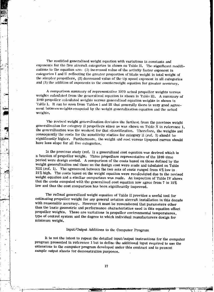
The modified generalized weight equation with variations in constants and
exponents for the five aircraft categories is shown on Table II. The significant modifi-cations to the equation are: (1) increased value of the activity factor exponent in
categories I m_d II reflecting the greater proportion of blade weight in total weight of
the simpler propellers_ (2) decreased vahm of the tip speed exponent in all categoriesand (3) the addition of exponents to the counterweight equation for greater accuracy.
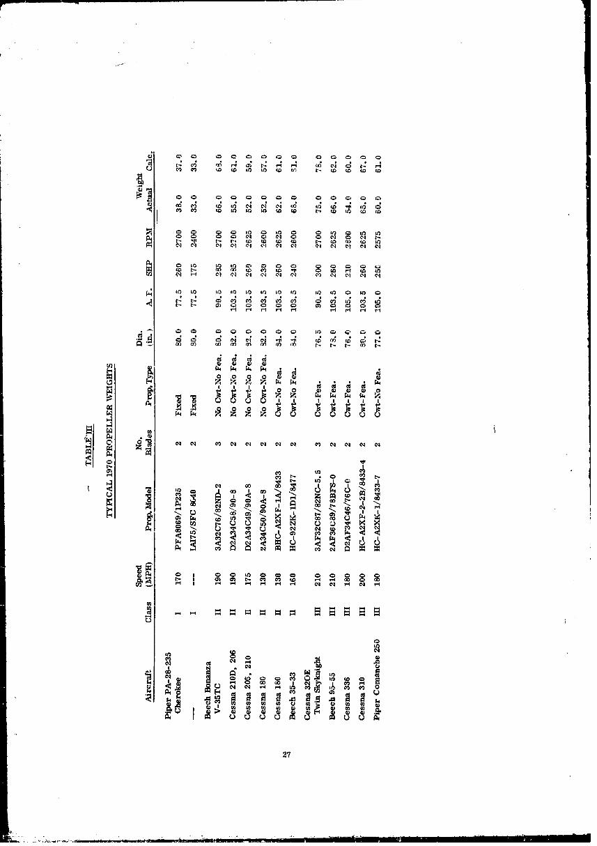
A comparison summary of representatiw_ 1.070 actual propeller weights versus
weights calculated from the genorMlzed equation is shown in Table III. A summary of
1980 propeller calculated weights versus generalized equation weights is shown inTable I, It can be seen from Tables I and III thaI; generally there is very good agree-ment botweenweights computed by the weight generalization equation and the actualwet ghts.
The revised weight generalization deviates the furthest from the previous weightgenerMlzation for category ll propellers since as was shown on Table X in reference 1,
the generalization was the weakest for that classification. Therefore, the weights and
coasoquently the costs for the sensitivity studies for category II (r_f. 1) should besignificantly higher. Furthermore, the weight _md cost versus tipspeed curves shouldhave less slope for M1 five categories.
In the previous study (ref. 1) a generalized cost equation was derived which isa function of propeller weight. Three propellers representative of the 1980 timeperiod were design costed. A comparison of the costs based on these defined by the
weight generalization and those on the design cost were made and tabulated on Table
XIII (ref. 1). The agreement between the two sets of costs ranged from 6% low to21% high. The costs baseu on the weight equation were recalculated due to the revisedweight equation and a similar comparison was made. An inspection of Table IV showsthat the costs computed with the generalized cost equation now agree from 7 to 15%
low and thus the cost comparison has been significantly improved.
The refined generalized weight equation of Table II provides a useful tool forestimating propeller weight for any general aviation aircraft installation in this decade
with reasonable accuracy. However it must be remembered that parameters otherthan the basic geometric and performance characteristics used in this equation effect
propeller weights. These are variations in propeller environmental temperatures,type of control system and the degree to which individual manufacturers design forminimum weight.
Input/Output Additions to the Computer Program
It is not the intent to repeat the detailed input/output instructions for the computerprogram presented in reference 1 but to define the additional input required to use the
extensions to the computer program developed under this contract and to presentsample output sheets for demonstration purposes.q
17
1972010354-TSC09
+_
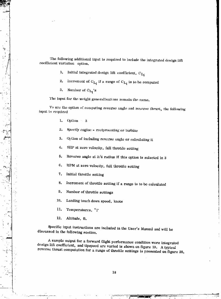
The following additional input is required to Include the integrated design liftcoefficient variation option.
1. Initial integrated design lift coefficient, CLi
2. Increment of CLI if a range of CLi is to be computed
3. Number of CLi'S
The input for the weight general, lzat|:ana remain the _ame.
To use the option of computing rever_e angle and reverse thrust, the following
ll_put Is required
1. Option :: 3
2, Specify engine - reciprocating or l,urbino
3. Option of including reverse anglo or calculating It
4. SHP at zero velocity, full throttle setting
5. Reverse angle at 3/4 radius if this option is selected in 3
6. RPM at zero velocity, full throttle setting
": 7. Initial throttle settingi
8. Increment of throttle setting if a range is to be calculated
9. Number of throttle settings[.'
.:: 10. Landing touch down speed, knots
11. Temperatures, °t'i
12. Altitude, ft.
Specific input instructions are included in the User's Manual ,and will be
discussed in the following section.
A sample output for a forward flight performance condition were integrateddesign lift coefficient, and tipspeed are varied is shown on figure 19. A typical
reverse thrust computation for a range of throttle settings is presented on figure 20.
18
............, .... ..... -̧, •
...... 1972010354-TSC10

r
USERtS MANUAL
19/2o
CONCLUDING REMARKS
,i.:
; i
21/22
1972010354-TSC13

REFERENCES
1. Worobel, R. and Mayo, M. : Advanced General Aviation Propeller Study.NASA Report CR 114289, April 1971
2. Worobel, R, : Computer Program User's Manual for Advanced GeneralAviation Propeller Studies. To be published as a NASA low numberContractor Report.
23/24
1972010354-TS[:)01

TABLEI
WEIGHT SUMMARY OF PROPELLERS STUDIED FOR 1980
Math No. Dla Weight (Lbs)Class No. Blades (Ft) A, F, SHP RPM Est. Eq,mtion
II 0.262 4 8 I00 300 955 103 941310 111 1041670 120 113
150 955 134 1341310 148 1501670 167 I_3
200 956 173 1741310 202 1941670 231 211
q 180 955 109 110
1310 122 1231670 130 133
IV 0.328 3 9 100 340 958 104 104IZ30 110 1121480 116 121
150 955 143 1481230 151 1591480 159 169
200 955 195 1951230 206 2081480 218 218
i
4 150 955 189 1841230 200 1971480 211 208
: V 0.368 4 lO 100 650 860 171 1641190 180 1801825 193 195
150 860 216 218
1190 234 2401525 259 259
200 860 263 2671190 287 2941525 318 317
3 150 860 171 1781190 186 1961525 214 212
25
1972010354-TSD02

TABLE II
GENERAL AVIATION
Generalized Propeller Weight Equation:
W'r _ Kw ('i-_) _t0n2] (M + 1)0. + c w
Where:
WT Pz'op. Wet Weight, lbs, (excludes spinner, deleing & governor)
D = Prop, Die, Ft,
B _ No. of Blados
A.F. Blade Activity Factor
N - Prop. Speed, RPM (take-off)
SHP Shaft Horsepower, ltP (take-off)
M = Nlach No. (Design Condition: Max Power Cruise)
CW : Y _1--_) 2 .- 0 = Counterweight Wt,, lbs.
K W, CW: u, v and y values for use in the weight equatlo:a are taken from table below:
Aircraft ['--¥e_ologyClass I 1970 1980 Kw u v y
--"_ ]_(1) [ (1) (1) 170 0.9 0.35 0I {
::_ _i I (2) I (2) (2) 200 0.9 0.3s 0' ::. III Ii (3) Ii (3) (3) 220 O. 7 0.,40 5.0
I Iiv I (3) I (4) (4> 190 0.7 0.40 3.B
I I
. ." VV _J (5) (5) 190 O.7 O. 30 0
?..: Propeller types a_sociated with above Kw and C w are as follows:"..k
•:i:,. (1) All fixed-pitch props.'2
(2) Me Cauley non-eotmterweighted, non-feathering, constant speed props
(3) All Hartzell, all Hamilton Standard small props, and feathering Mc Cauley
(4) Fiberglass-bladed, constant speed, counterwetghted, full feathered
(5) Fiberglass-bladed, constant-speed, double-acting (non-counterweighted), fall feathered,reverst,
• 26
t_ I_. tO tO to tO
I0 I0 _0 tO iO _ if) iO I0 I0 0 I0 0
Lr__D _I
_@? _ ,_ _
2?
1972010354-TSD04
28
"IE}720"10354-TSD05

TABLE IV
O. E.M. SINGLE UNIT COST SUMMARY OF
REPRESENTATIVE _ROPELLEtiS FOR 1980
Generalized Calmllated
Equation Desll_l CostCost Cost Variation
Category $/lb $/lb %
II 27 29.1 +7
IV 35 38.5 +10
V :35 41.2 +15
29
1972010354-TSD06

•.: _ o
1972010354-TSD07
Q
81
1g72010354-TSD08

FIGURE 3. CAMBER FACTOR ADJUSTMENT FOR ADVANCE RATIO

CPE2 =CPx PAFX PBLX PFCLI
00 0.2 0.4 0.6 0.8 1.0
EFFECTIVE POWER COEFFICIENT, CPE 2
FIGURE 4o INTEGRATED DESIGN LIFT COEFFICIENT ADJUSTMENT TO POWERCOEFFICIENT FOR 4--BLADED PROPELLERS
33
, ° •......... ,..........._..._.._._:_ .... ' :. : .... _._-_--_--_-_ .-..:-.._:/,-.-tk._.;v-.......... _--._._-_...... " _'_ --b,_ ,,, , " _ ' - ' ' _---_-_
1972010354-TSDJ 0

.___
i
0
' 1972010354-TSD11
CTE 2= CT X TAI.- X TBL X TFCLi2.8;
00 0,1 0.2 0,3 0.4
EFFECTIVE THRUST COEFFICIENTt CTE 2
FIGURE 6, INTEGRATED DESIGN LIFT COEFFICIENT ADJUSTMENT TOTHRUST COEFFICIENT FOR 4--BLADED PROPELLERS
35
1972010354-TSD13

36
....... _ .. - " - - : ,.... : _. _ .___- _ ,1 II ""---'-I
1972010354-TSF01
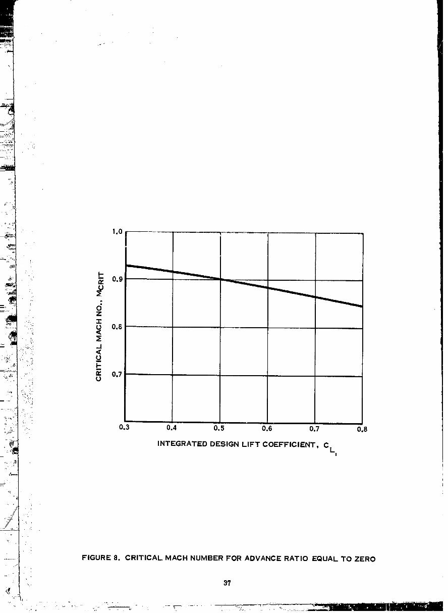
FIGURE 8. CRITICAL MACH NUMBER FOR ADVANCE RATIO EQUAL TO ZERO
37
1972010354-TSF02
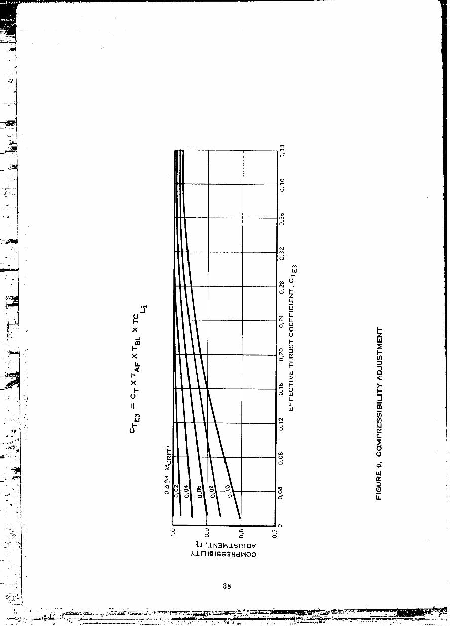
38

600
_, _ _..___ ___._/3=-12'9 °, 100% THROTTLE SETTING500
b')
• 40C II
__ I
" /33/4 -----9.2° ' 60%• __
_: 300 _
:£ILn,
22oo
bl
O 2100
a.
2000 L0 10 20 30 40 50 60 70
LANDING SPEEDS, KNOTS
FIGURE 10. EXAMPLE REVERSE THRUST VARIATION WITH LANDINGSPEED AND POWER SETTING
39
1972010354-TSF04

•._. FIGURE 11. ACTIVITY FACTOR ADJUSTMENT TO TORQUE COEFFICIENT
" : 4o
1972010354-TSF05

J<_.1.0
FIGURE 12. INTEGRATED DESIGN LIFT COEFFICIENT AD IUSTMENTTO TORQUE COEFFICIENT
1972010354-TSF06

0100 .............
//:U) 70
ooo_°o_ / /_'d 5o
..:.- I_Z•" _9 30•" _I-
• (D n, 20_, Q:::Q::
.. ': Q- 0 ,: 10
o _--30 --20 -- 10 0 10
BLADE ANGLE, /33/4
• 4,
.: FIGURE 13. VARIATION OF PERCENTAGE OF INTEGRATED DESIGN LIFT• COEFFICIENT CORRECTION REQUIRED FOR THRUST AND TORQUE

0-30 -20 --10 0 10
BLADE ANGLE, /3 3/4
FIGURE 14. BASIC PERFORMANCE CURVE VARIATION OF EFFECTIVE TORQUECOEFFICIENT WITH ADVANCE RATIO & BLADE ANGLE
43
_ : _ "_ ,. /7 ,_ ;, ;;,•, . r_ ,., ' :_................ _.,%'_=t_ ,. -,,,_w,=_=---"_'----_--'_'_"_"_,_._'"-----_,_Y'_,;,_.jj{+#_ -_ ...... 4. ,=.,'J_;_=;'C=_=_,,..
1972010354-TSF08

FIGURE 15. INTEGRATED DESIGN LIFT COEFFICIENT ADJUSTMENTTO TORQUE COEFFICIENT
,t,t
1972010354-TSF09

3 BLADES/IOOAF/0.4 CLi
-0.4 . -
0.. --30 -20 -10 0 10
--0.4 - -
J.0' _ I.d -0.3
. _ I- _" __
: IZ O _ no
0-30 -20 -10 0 10
' BLADE ANGLE,/3 3/4
!
FIGURE 16. BASIC PERFORMANCE CURVE VARIATION OF EFFECTIVE THRUSTCOEFFICIENT WITH ADVANCE RATIO & BLADE ANGLE
,t5
1972010354-TSF10
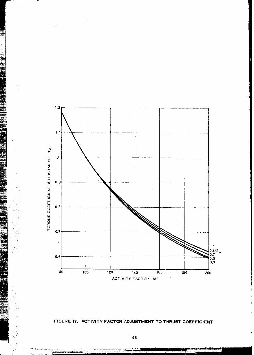
80 100 120 140 160 180 200
ACTIVITY FACTOR, AF'
:;t'
FIGURE 17. ACTIVITY FACTOR ADJUSTMENT TO THRU6T COEFFICIENT
'" 46
1972010354-TSF11

_TcE 2 = ACTE2x0/J) 2 (J>1.0)F-(J 0,04q
0.03
J<1.0__ O.02
,.. _ 0.01• m
i
h 0hhl
;' 0
, 0 -0.01
• .-.on_:Z: 0.3 0.4 0.5 0.6 0.7 0.8
INTEGRATED DESIGN LIFT COEFFICIENT, CLi
FIGURE 18. INTEGRATED DESIGN LIFT COEFFICIENT ADJUSTMENTTO THRUST COEFFICIENT
.... 49
.......... 1972010354-TSF13 --

48
1972010354-TSG01

- HAMILTON STANDARD COMPUTER DECK NO. H632COMPUTES PERFORMANCEpNOTSFtHE|GHTtAND COST FOR
GENERAL AVIATION PROPELLERS
1 CLASSIFICATION 5 AIRPLANE SAMPLE CASE II
2 REVERSE THRUST OPTION
REVERSF THRUST COHPUTATION
EFCIPROCATING ENGINE
NOFMAL RA_EC SHP = 550,NORMAL RATEO RPM = 2200.TOUCH DOHN V-KNOTS = 72.
NUNBER OF BLADES= 3. ACTIVITY FACTOR=t09. INTEGRATED CESIGN CL=.509
THROTTLE REVERSE REVERSEDTA;_T SFTTING ANGLE V-KNCTS THRUST SHP RPN
.... K._ 100. -12.9 C.O 524. 550. 2199,10.0 615. 547. 2188.?0.0 714. 543. 2172.30.0 822. 538. 2151.40.0 938. 531. 2124.50.0 1059. 523. 2092.
" 60.0 117q. 514. 2056.70.0 1313. 503. 2013,72.0 1342. 501. 2004.
8.5 80. -11.2 0.0 380. 460. 21q8.IO.O 468. 437. 2187,20.0 565. 434. 2170.30.0 673. 430. 21_9.60.0 790. 425. 2124.50.0 913. 419. 2093.60.0 1035. 612. 2059.70.0 1173. 406. 2019,72.0 1204. 402. 2010.
8._ 60. -9.2 0.0 208. 330. 2200.10.0 293_ 328. 2184.20.0 388. 325. 2165.30.0 4q5. 321. 2143.40.0 612. 318. 2117._0.0 737. 313. 2087.60.0 861. 308. 2054.70.0 1002. 303. 2018.72.0 103_. 302. 2010,
FIGURE 20. SAMPLE CASE II OF COMPUTER PROGRAM OUTPUT
49/50
1972010354-TSG02