advanced h s and co removal technologies for...
TRANSCRIPT

Advanced H2 S and CO2 Removal Technologies for Synthesis Gases
>
Howard S. Meyer, R&D Director Shaojun (James) Zhou, Senior Engineer
Dennis Leppin, Senior Institute Engineer>
Gas Technology Institute Des Plaines, IL USA
May 2010

Advanced H2S and CO2 Removal Technologies for Synthesis Gases 2
INDIANA UTILITY REGULATORY COMMISSION JUNE 15, 2005 E-Gas Technology for Coal Gasificationhttp://www.narucpartnerships.org/Presentations/Albania/June05/Site%20visits/Terre_Haute_Wabbash_Coal_Gasification_Plant.pdf#search=%22egas%20gasification%22
Partial Gasification Schematic
CO2

Advanced H2S and CO2 Removal Technologies for Synthesis Gases 3
Clean Syngas Targets
Contaminant Maximum After Cleanup
H2
S 50 ppbw
NH3 0.1 vol%
HCl 1 ppm
Hg 5 ppbw
Se 0.2 ppm
As 5 ppb
Cd 30 ppb
CO2 10% of CO2 produced

Advanced H2S and CO2 Removal Technologies for Synthesis Gases 44Advanced H2S and CO2 Removal Technologies for Synthesis Gases
Technology Outline

Advanced H2S and CO2 Removal Technologies for Synthesis Gases 5
UCSRP-HP Process Development

Advanced H2S and CO2 Removal Technologies for Synthesis Gases 66Advanced H2S and CO2 Removal Technologies for Synthesis Gases
UC Sulfur Recovery ProcessUC Sulfur Recovery Process
>Multi-contaminant removal process>Compound column at temperatures
─
above the sulfur melting point of 247°F (119°C) ─
below the polymerization temperature of 310°F (154°C)
>In the bottom half of tower, HCl, NH3
, and trace heavy metals (Hg, As, Se and Cd ) are removed
>In top half, H2
S reacts with injected excess SO2 in a catalyzed solvent circulating in counter-current or co-current manner

Advanced H2S and CO2 Removal Technologies for Synthesis Gases 7
MultiMulti--Contaminant Cleanup Contaminant Cleanup ConceptConcept
NH4
Cl, (NH4
)2
Se, AsS, CdS, HgS
DEG, H2
O, NH3
, H2
S
DEG(Section A)
DGM + Catalyst (Section B)
SO2
Added
Partially Clean Syngas:
H2
S, COS, & NH3
H2
S & COS removedNH3, SO2
Clean SyngasDGM + Catalyst
SO2
and NH3
Depleted
Dirty Syngas:H2
S, COS, HCl, NH3
, As, Cd, Hg, Se
Includes immiscible liquid sulfur, NH3
, SO22 H
2S +
SO
2
3S +
2 H
2O

Advanced H2S and CO2 Removal Technologies for Synthesis Gases 88Advanced H2S and CO2 Removal Technologies for Synthesis Gases
Degradation/Stability
29% H2
; 41% CO; 16% N2
; 11% CO2
; 7651ppm H2
S
1% SO2
in Balance Nitrogen

Advanced H2S and CO2 Removal Technologies for Synthesis Gases 99Advanced H2S and CO2 Removal Technologies for Synthesis Gases
>
1,000 hour test>
Sulfur purity at 99.2% •
Major consumer purity specs 99.5-99.9%
>
2.3% of DEG/solvent degraded to tetraglyme•
Less volatile product
•
H2
S more soluble in tetraglyme•
Viscosity versus solubility
>
25% of catalyst (3-pyridyl carbinol) at 0.2% by weight of solution broke down to 3-
methylpyridine and 4-formylpyridine. •
Did not appear to effect reactivity.
>
COS formed at 35 ppm
Degradation/Stability Results
Advanced H2S and CO2 Removal Technologies for Synthesis Gases 10
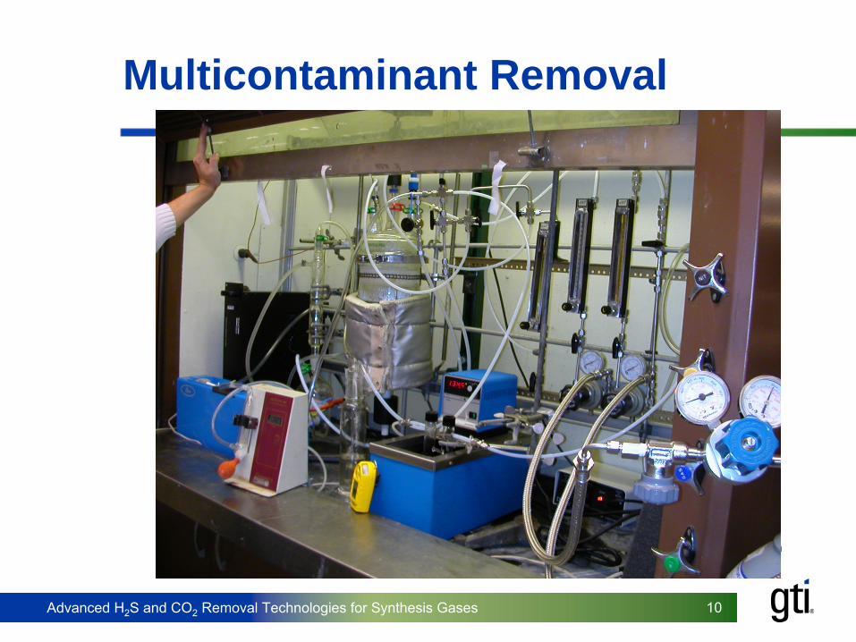
Multicontaminant Removal

Advanced H2S and CO2 Removal Technologies for Synthesis Gases 11
Mercury Removal
05000
10000
15000200002500030000
350004000045000
0 1000 2000 3000 4000 5000 6000 7000
Time, sec
Hg
Con
cent
ratio
n,ng
/m 3
.
95% Mercury Removal with DEG as solvent

Advanced H2S and CO2 Removal Technologies for Synthesis Gases 1212Advanced H2S and CO2 Removal Technologies for Synthesis Gases
Bench-scale Unit

Advanced H2S and CO2 Removal Technologies for Synthesis Gases 1313Advanced H2S and CO2 Removal Technologies for Synthesis Gases
Summary of Results
>Elemental sulfur 99.2% close to target w/o processing
>Mercury removal to less than 0.2 ppb>Catalyst is active after 1000 hour test >Corrosion rates very low for carbon steel>50% H2
Se & 33% AsH3
removed in single stage scrub

Advanced H2S and CO2 Removal Technologies for Synthesis Gases 14
Morphysorb® Syngas Treating Process

Advanced H2S and CO2 Removal Technologies for Synthesis Gases 15
Morphysorb Process
>
What is it?–
Proprietary solvent/process(GTI and Uhde own the technology)
–
N- formyl morpholine/N-acetyl morpholine mixtures
>
What is the application?–
Bulk or trace removal of acid gas components –
Subquality natural gas upgrading to either pipeline or LNG specification
–
Selective removal of H2 S from natural/synthesis gas for generation of acid gas stream suitable for Claus plant feed
–
Selective removal of H2 S, CO2 , COS, CS2 , mercaptans and other components from coal/oil gasification syngas at IGCC facilities

Advanced H2S and CO2 Removal Technologies for Synthesis Gases 16
Morphysorb Process>
Advantages–
Higher solvent loading = lower circulation or higher throughput
–
Lower co-absorption of hydrocarbons (less losses)-less recycle gas flow
–
Lower CO and H2 absorption
–
In situ, partial COS Hydrolysis
–
Low corrosion, low environmental hazard
–
Low capital and operating costs
Advanced H2S and CO2 Removal Technologies for Synthesis Gases 17
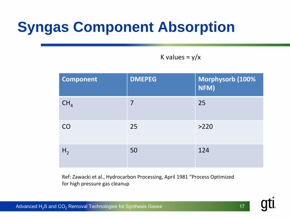
Syngas Component Absorption
Component DMEPEG Morphysorb (100%
NFM)
CH4 7 25
CO 25 >220
H2 50 124
Ref: Zawacki et al., Hydrocarbon Processing, April 1981 “Process Optimized for high pressure gas cleanup
K values = y/x

Advanced H2S and CO2 Removal Technologies for Synthesis Gases 1818Advanced H2S and CO2 Removal Technologies for Synthesis Gases
>Kwoen Gas Plant Plant started in late 2002>Owned by Spectra EnergySM
Transmission>300 MMscfd (8.5 m3/d) orig., 450 MMscfd (12.75
m3/d) expansion>Bulk removal of 25+% acid gas concentration
stream>~4500 gpm (1000 m3/h) circulation>~2000 psia (13.8 MPa) liquefied acid gas to
injection Spectra Energy Kwoen Plant
ca.
2002
Absorber towers
Solvent storage
Flash drums
Natural Gas Commercial Application

Advanced H2S and CO2 Removal Technologies for Synthesis Gases 19
Acid Gas Treating Pilot Plant
Orig. 15 gpm (15 L/m)unit
Upgraded 40 gpm (150 L/m)
unit at GTI, Des Plaines, IL
Can process full flow from GTI Flex Fuel Test Facility 10‐20 TPD gasifier
~ 1MMscfd (28,000 Nm3 /hr)

Advanced H2S and CO2 Removal Technologies for Synthesis Gases 2020Advanced H2S and CO2 Removal Technologies for Synthesis Gases
AGTPP
> Absorber ─
33.5 ft. (10.2 m) of packed height
─
14.7 inches (37 cm) internal diameter ─
Koch Type 350Y Flexipac elements
─
1200 psi (~80 bar) maximum operating pressure
> Regenerator ─
40.7 ft. (12.4 m) of packed height
─
12 inches internal diameter (30.5 cm) ─
Koch Type 350Y Flexipac elements
─
50 psig (4.5 bara) maximum operating pressure

Advanced H2S and CO2 Removal Technologies for Synthesis Gases 2121Advanced H2S and CO2 Removal Technologies for Synthesis Gases
Morphysorb Conclusions
>
Natural gas bulk removal application - proven very reliable and efficient
>
Syngas treating - May be viable and beneficial but pilot plant data are needed, at a minimum
>
Solvent swap may be possible, as done for natural gas
>
A competitor to existing physical solvent options would be of value to the budding gasification industry to keep prices competitive
>
GTI/Uhde will continue to advance Morphysorb for multiple applications throughout studies, pilot and demonstration applications
Advanced H2S and CO2 Removal Technologies for Synthesis Gases 22
CarboLock Carbon Capture Device

Advanced H2S and CO2 Removal Technologies for Synthesis Gases 2323Advanced H2S and CO2 Removal Technologies for Synthesis Gases
Advantages of The Membrane Contactor Process
The gas/liquid contactor is a hybrid between membrane and the conventional absorption processes. Process features:Counter-current flow is thermodynamically most efficient mass transferStructured packing of hollow fibers critical for efficient, high specific surface area, mass transfer. Computer controlled winding enhances turbulence flow at fiber surfaceHigh temperature stability for desorption stepIncreased mass transfer reduces system sizeIndependent gas and liquid flowLinear scale upConcentrated solvents or specialty absorbents can be used

Advanced H2S and CO2 Removal Technologies for Synthesis Gases 2424Advanced H2S and CO2 Removal Technologies for Synthesis Gases
Membrane Material Properties of PEEK
Very high heat resistance, rigidity & strengthExcellent sliding friction behavior, minimal abrasionExcellent chemical resistanceExcellent hydrolytic stabilityAverage pore size can be tailored from 1 to 50 nmPore morphology can be symmetric or asymmetricAverage porosity can range from 50 to 70%800 psi (5.5 MPa) water breakthrough pressure
PEEK Hollow Fiber
PEEK can operate continuously in contact with aggressive amine solvents

Advanced H2S and CO2 Removal Technologies for Synthesis Gases 2525Advanced H2S and CO2 Removal Technologies for Synthesis Gases
Benefits of Integral Membrane/ Absorption Process
Membrane Advantages:•Capital Cost (CapEx) 35%•Operating Costs (OpEx) 40%•Dry Equipment Weight 35%•Operating Equipment Weight 37%•Total Operating Weight 47% •Footprint Requirement 40%•Height Requirement 60%
*Data by Aker Kvaerner
Conventional AmineScrubber Column
Membrane Contactor

Advanced H2S and CO2 Removal Technologies for Synthesis Gases 2626Advanced H2S and CO2 Removal Technologies for Synthesis Gases
Module Fabrication
Tubesheet material•
Specialty epoxies compatible with amines and other solvents
Well established potting process
Module area up to 1000 ft2 (100 m2) and module diameter from 2 to 12 inches (5 to 30 cm)
Structured packing attained by computer-controlled hollow fiber helical winding processLow pressure drop and high mass transfer rate obtained
Advanced H2S and CO2 Removal Technologies for Synthesis Gases 27
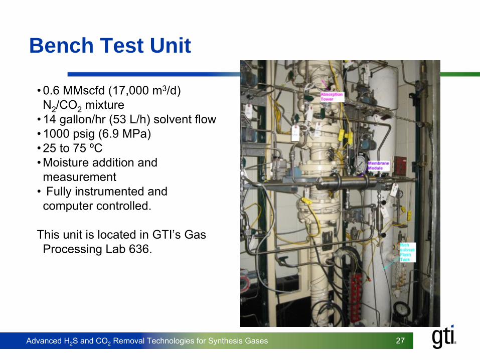
Bench Test Unit
•
0.6 MMscfd (17,000 m3/d) N2
/CO2
mixture•
14 gallon/hr (53 L/h) solvent flow
•
1000 psig (6.9 MPa)•
25 to 75 ºC
•
Moisture addition and measurement
•
Fully instrumented and computer controlled.
This unit is located in GTI’s Gas Processing Lab 636.
Advanced H2S and CO2 Removal Technologies for Synthesis Gases 2828Advanced H2S and CO2 Removal Technologies for Synthesis Gases
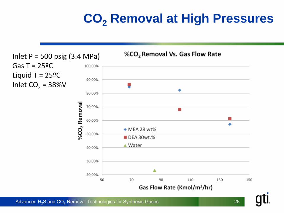
CO2 Removal at High Pressures
Inlet P = 500 psig (3.4 MPa)Gas T = 25ºCLiquid T = 25ºCInlet CO2
= 38%V

Advanced H2S and CO2 Removal Technologies for Synthesis Gases 2929Advanced H2S and CO2 Removal Technologies for Synthesis Gases
Technology Status – Modeling
•
Applications for the simulation program (absorption):Low pressure CO2-removal (exhaust gas) – MEALow pressure CO2-removal (exhaust gas) – MDEA/PiperazineDehydration / H2O-removal (natural gas) – TEGSweetening / CO2 and H2S removal (natural gas) –MDEA/PiperazineSweetening / CO2 and H2S removal (natural gas) – Sulfinol-DSweetening / CO2 and H2S removal (natural gas) – Morphysorb
•
Applications for the simulation program (desorption):CO2 / MEACO2 / MDEA

Advanced H2S and CO2 Removal Technologies for Synthesis Gases 3030Advanced H2S and CO2 Removal Technologies for Synthesis Gases
Conclusions
>No “silver bullet”
process that can treat gas to IGCC or XtL
specs
>New integrated processes provide potential for energy and cost savings
>GTI is seeking opportunities to advance these technologies to help advance IGCC and XtL
projects