advanced himawari imager (ahi) design and …€¦ · · 2015-11-11advanced himawari imager (ahi)...
TRANSCRIPT

| Harris Proprietary Information | 0 |
This document is not export controlled. Use or disclosure of this information
is subject to the restrictions on the Title Page of this document.
AHI Design (AOMSUC-6) | 0 harris.com
Dr. Paul C. Griffith Sixth Asia/Oceania Meteorological Satellite Users'
Conference, Tokyo, Japan, 10 November 2015
Advanced Himawari Imager
(AHI) Design and Operational
Flexibility
This document is not subject to the controls of the International Traffic in
Arms Regulations (ITAR) or the Export Administration Regulations (EAR).
| Harris Proprietary Information | 1 |
This document is not export controlled. Use or disclosure of this information
is subject to the restrictions on the Title Page of this document.
AHI Design (AOMSUC-6) | 1
AHI – Paradigm Shift in Geostationary
Weather Imaging
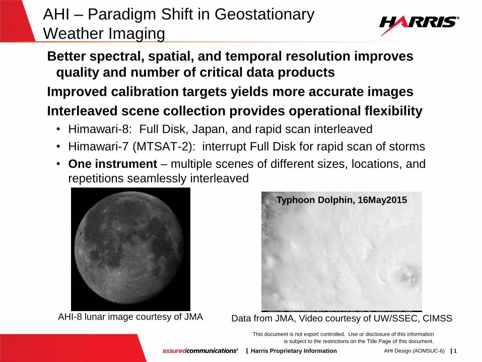
Better spectral, spatial, and temporal resolution improves
quality and number of critical data products
Improved calibration targets yields more accurate images
Interleaved scene collection provides operational flexibility
• Himawari-8: Full Disk, Japan, and rapid scan interleaved
• Himawari-7 (MTSAT-2): interrupt Full Disk for rapid scan of storms
• One instrument – multiple scenes of different sizes, locations, and
repetitions seamlessly interleaved
AHI-8 lunar image courtesy of JMA Data from JMA, Video courtesy of UW/SSEC, CIMSS
Typhoon Dolphin, 16May2015
| Harris Proprietary Information | 2 |
This document is not export controlled. Use or disclosure of this information
is subject to the restrictions on the Title Page of this document.
AHI Design (AOMSUC-6) | 2
Agenda
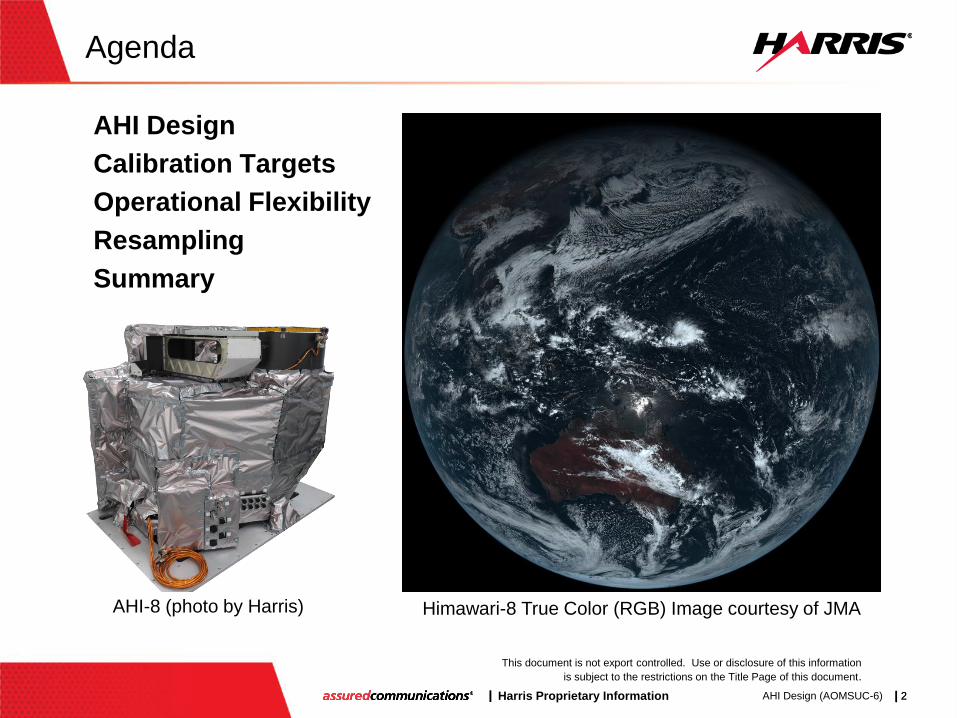
AHI Design
Calibration Targets
Operational Flexibility
Resampling
Summary
Himawari-8 True Color (RGB) Image courtesy of JMA AHI-8 (photo by Harris)
| Harris Proprietary Information | 3 |
This document is not export controlled. Use or disclosure of this information
is subject to the restrictions on the Title Page of this document.
AHI Design (AOMSUC-6) | 3
AHI-8: First Next Generation
Geostationary Imager On Orbit
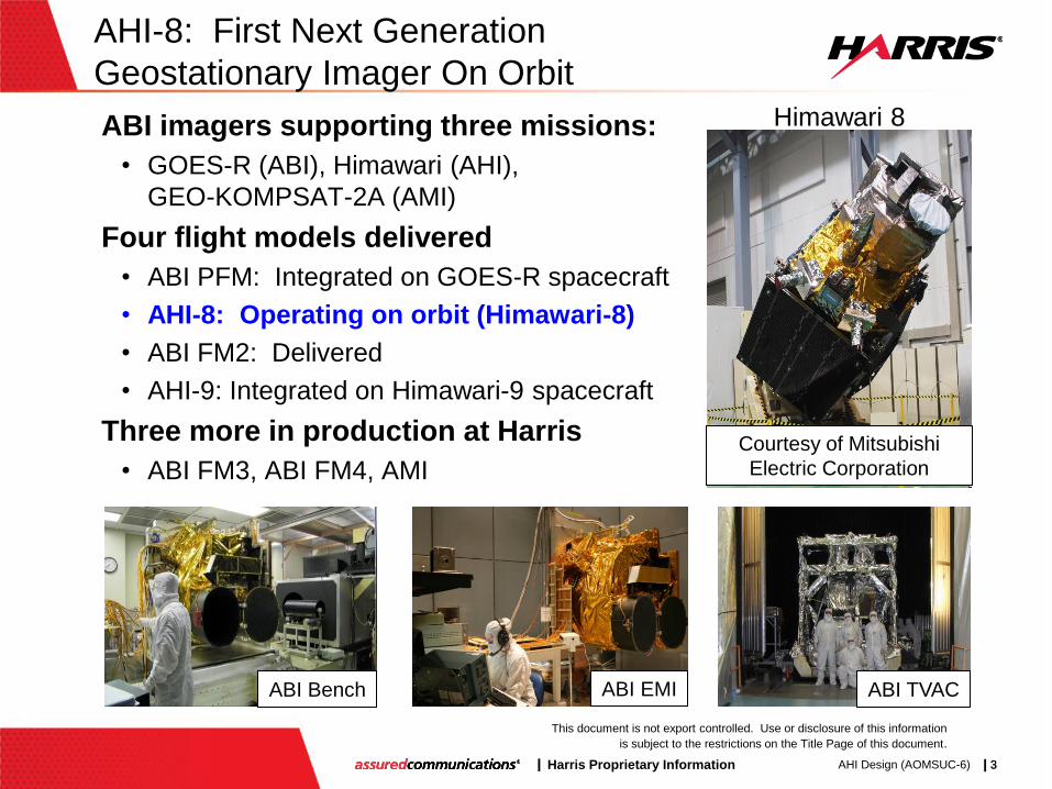
ABI imagers supporting three missions:
• GOES-R (ABI), Himawari (AHI),
GEO-KOMPSAT-2A (AMI)
Four flight models delivered
• ABI PFM: Integrated on GOES-R spacecraft
• AHI-8: Operating on orbit (Himawari-8)
• ABI FM2: Delivered
• AHI-9: Integrated on Himawari-9 spacecraft
Three more in production at Harris
• ABI FM3, ABI FM4, AMI
Courtesy of Mitsubishi
Electric Corporation
Himawari 8
ABI Bench ABI EMI ABI TVAC
| Harris Proprietary Information | 4 |
This document is not export controlled. Use or disclosure of this information
is subject to the restrictions on the Title Page of this document.
AHI Design (AOMSUC-6) | 4
AHI’s 2-Mirror Scanner Key to Operational
Flexibility
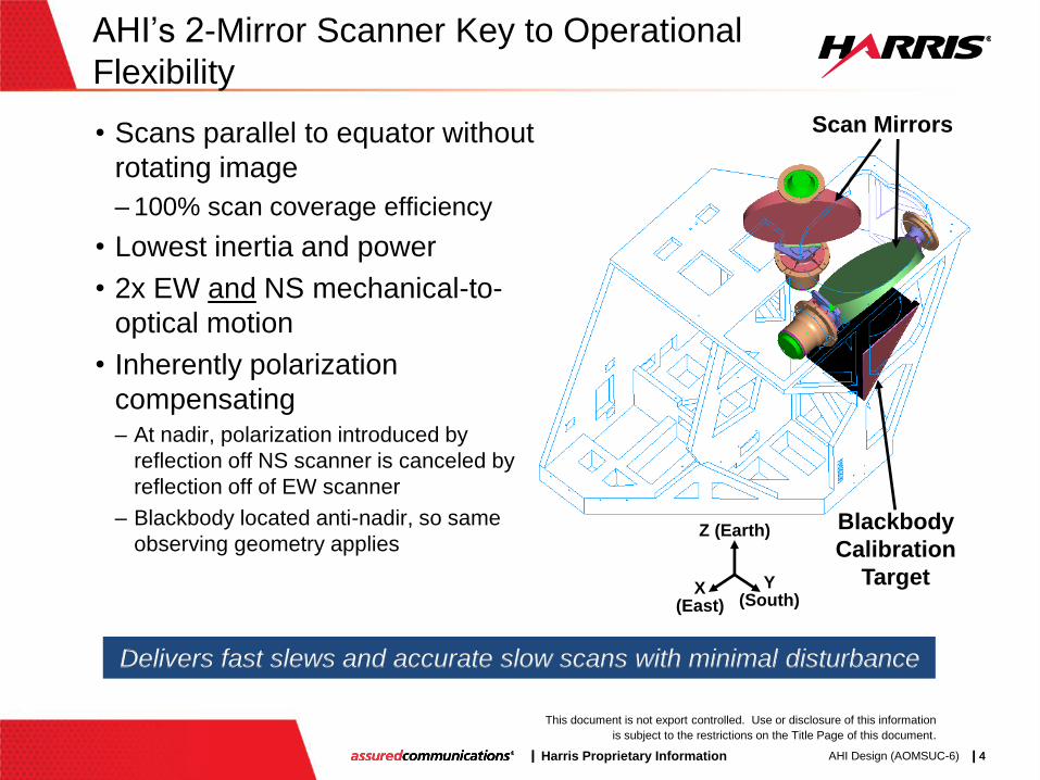
Scan Mirrors
Blackbody
Calibration
Target Y (South)
Z (Earth)
X (East)
Delivers fast slews and accurate slow scans with minimal disturbance
• Scans parallel to equator without
rotating image
– 100% scan coverage efficiency
• Lowest inertia and power
• 2x EW and NS mechanical-to-
optical motion
• Inherently polarization
compensating – At nadir, polarization introduced by
reflection off NS scanner is canceled by
reflection off of EW scanner
– Blackbody located anti-nadir, so same
observing geometry applies

| Harris Proprietary Information | 5 |
This document is not export controlled. Use or disclosure of this information
is subject to the restrictions on the Title Page of this document.
AHI Design (AOMSUC-6) | 5
CS
VNIR Bands 1-6
(170 K)
BS2
MWIR Bands 7-11
(60 K) LWIR
Bands 12-16
(60 K)
SM1
(NS)
Scan
Mirrors
SM2
(EW)
Exit Pupil
Fold
Mirror
W1
BS1
W2
W3
60 K
170 K
300 K
CS, S2, MWIR
& LWIR FPMs
W3, VNIR FPM
Remaining structure
AHI Optical Architecture:
Simple Solution to Mission Needs
-Y
FMA
Telescope +X
-Z
| Harris Proprietary Information | 6 |
This document is not export controlled. Use or disclosure of this information
is subject to the restrictions on the Title Page of this document.
AHI Design (AOMSUC-6) | 6
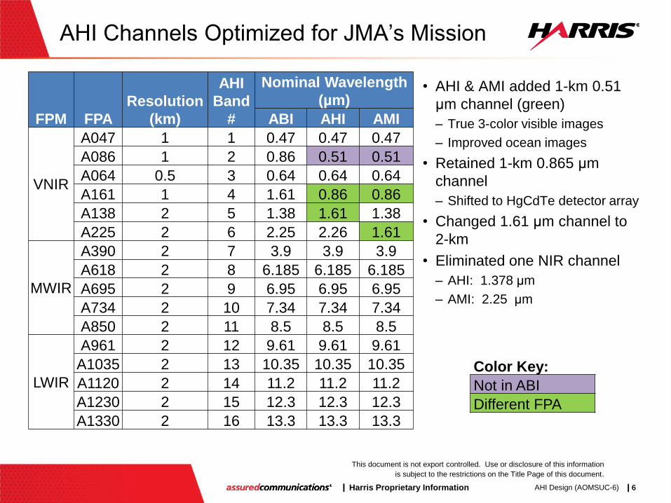
AHI Channels Optimized for JMA’s Mission
• AHI & AMI added 1-km 0.51
μm channel (green)
– True 3-color visible images
– Improved ocean images
• Retained 1-km 0.865 μm
channel
– Shifted to HgCdTe detector array
• Changed 1.61 μm channel to
2-km
• Eliminated one NIR channel
– AHI: 1.378 μm
– AMI: 2.25 μm
Color Key:
Not in ABI
Different FPA
FPM FPA
Resolution
(km)
AHI
Band
#
Nominal Wavelength
(µm)
ABI AHI AMI
VNIR
A047 1 1 0.47 0.47 0.47
A086 1 2 0.86 0.51 0.51
A064 0.5 3 0.64 0.64 0.64
A161 1 4 1.61 0.86 0.86
A138 2 5 1.38 1.61 1.38
A225 2 6 2.25 2.26 1.61
MWIR
A390 2 7 3.9 3.9 3.9
A618 2 8 6.185 6.185 6.185
A695 2 9 6.95 6.95 6.95
A734 2 10 7.34 7.34 7.34
A850 2 11 8.5 8.5 8.5
LWIR
A961 2 12 9.61 9.61 9.61
A1035 2 13 10.35 10.35 10.35
A1120 2 14 11.2 11.2 11.2
A1230 2 15 12.3 12.3 12.3
A1330 2 16 13.3 13.3 13.3
| Harris Proprietary Information | 7 |
This document is not export controlled. Use or disclosure of this information
is subject to the restrictions on the Title Page of this document.
AHI Design (AOMSUC-6) | 7
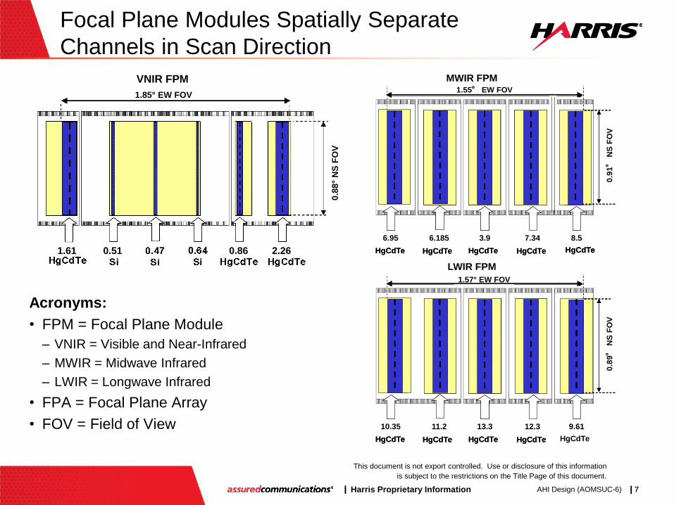
Focal Plane Modules Spatially Separate
Channels in Scan Direction
Acronyms:
• FPM = Focal Plane Module
– VNIR = Visible and Near-Infrared
– MWIR = Midwave Infrared
– LWIR = Longwave Infrared
• FPA = Focal Plane Array
• FOV = Field of View
1.78°EW FOV (33.6 mm)
0.9°
NS
FO
V
2.25
VNIR FPM1.9° EW FOV
0.8
8°
NS
FO
V
1.85° EW FOV
1.61 0.51 0.86 2.26
VNIR FPM
6.95
HgCdTe
3.90
HgCdTe
7.34
HgCdTe
8.50
HgCdTe6.185
HgCdTe
6.95
HgCdTe
3.90
HgCdTe
7.34
HgCdTe
8.50
HgCdTe6.185
HgCdTe
0.9
1°
NS
FO
V
1.55° EW FOV
9 8 7 10 116.95 6.185 8.53.9 7.34
MWIR FPM
10.35
HgCdTe
13.30
HgCdTe
12.30
HgCdTe
9.61
HgCdTe11.20
HgCdTeHgCdTe HgCdTe HgCdTeHgCdTe
0.8
9°
NS
FO
V
1.6 ° EW FOV
13 14 16 15 12
1.57° EW FOV
LWIR FPM
10.35 11.2 9.6113.3 12.3
| Harris Proprietary Information | 8 |
This document is not export controlled. Use or disclosure of this information
is subject to the restrictions on the Title Page of this document.
AHI Design (AOMSUC-6) | 8
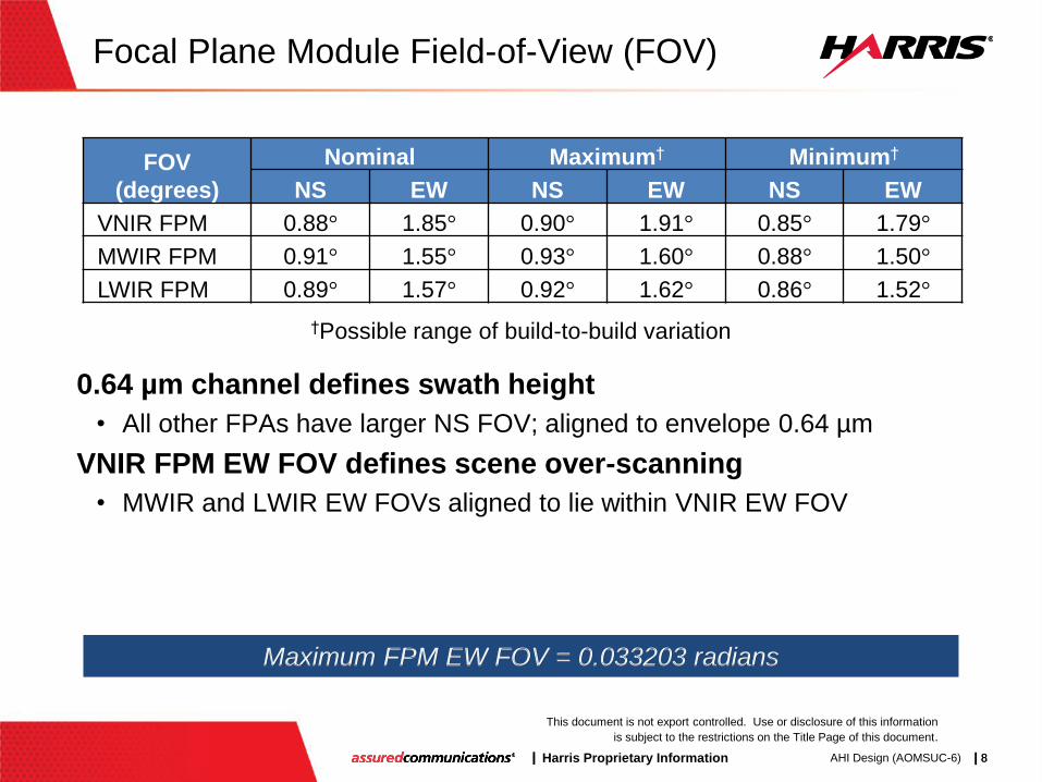
Focal Plane Module Field-of-View (FOV)
0.64 µm channel defines swath height
• All other FPAs have larger NS FOV; aligned to envelope 0.64 µm
VNIR FPM EW FOV defines scene over-scanning
• MWIR and LWIR EW FOVs aligned to lie within VNIR EW FOV
FOV
(degrees)
Nominal Maximum† Minimum†
NS EW NS EW NS EW
VNIR FPM 0.88° 1.85° 0.90° 1.91° 0.85° 1.79°
MWIR FPM 0.91° 1.55° 0.93° 1.60° 0.88° 1.50°
LWIR FPM 0.89° 1.57° 0.92° 1.62° 0.86° 1.52°
Maximum FPM EW FOV = 0.033203 radians
†Possible range of build-to-build variation

| Harris Proprietary Information | 9 |
This document is not export controlled. Use or disclosure of this information
is subject to the restrictions on the Title Page of this document.
AHI Design (AOMSUC-6) | 9
⁞ ⁞ ⁞ ⁞ ⁞ ⁞ ⁞ ⁞ ⁞ ⁞ ⁞ ⁞ ⁞ ⁞ ⁞ ⁞ ⁞ ⁞ ⁞ ⁞ ⁞ ⁞
Side 1 Side 2
Detector Selection Capability Provides
Operational Redundancy and Optimization
Non-compliant element
Compliant element
Selected element
Select best element in each row
Externally: Line array
Internally: 2D array
Requirement: one operational element per downlinked row per side
Color Key:
Ground
Guard
Active Detector Element
Separation
| Harris Proprietary Information | 10 |
This document is not export controlled. Use or disclosure of this information
is subject to the restrictions on the Title Page of this document.
AHI Design (AOMSUC-6) | 10
Best Detector Select (BDS) Map Can Be
Updated In Orbit
All detector elements characterized using on-board targets,
spacelooks, and/or stable vicarious calibration targets
• Zero radiance and “typical” radiance scenes
• Performed for all detector elements in each column
“Best” detector element in each row selected
• Operable – i.e. responds to light
• Median quantum efficiency
• Low noise – but not unrealistically low
• No popcorn noise
• Minimal long term drift
Updated BDS map uploaded to instrument
| Harris Proprietary Information | 11 |
This document is not export controlled. Use or disclosure of this information
is subject to the restrictions on the Title Page of this document.
AHI Design (AOMSUC-6) | 11
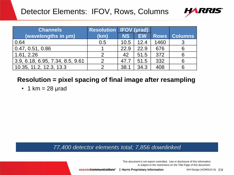
Detector Elements: IFOV, Rows, Columns
Resolution = pixel spacing of final image after resampling
• 1 km = 28 μrad
Channels
(wavelengths in µm)
Resolution
(km)
IFOV (µrad)
Rows Columns NS EW
0.64 0.5 10.5 12.4 1460 3
0.47, 0.51, 0.86 1 22.9 22.9 676 6
1.61, 2.26 2 42 51.5 372 6
3.9, 6.18, 6.95, 7.34, 8.5, 9.61 2 47.7 51.5 332 6
10.35, 11.2, 12.3, 13.3 2 38.1 34.3 408 6
77,400 detector elements total; 7,856 downlinked
| Harris Proprietary Information | 12 |
This document is not export controlled. Use or disclosure of this information
is subject to the restrictions on the Title Page of this document.
AHI Design (AOMSUC-6) | 12
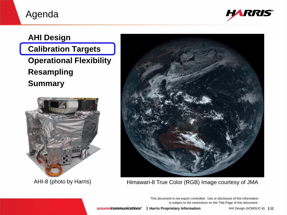
Agenda
AHI Design
Calibration Targets
Operational Flexibility
Resampling
Summary
Himawari-8 True Color (RGB) Image courtesy of JMA AHI-8 (photo by Harris)
| Harris Proprietary Information | 13 |
This document is not export controlled. Use or disclosure of this information
is subject to the restrictions on the Title Page of this document.
AHI Design (AOMSUC-6) | 13
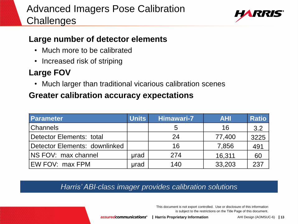
Advanced Imagers Pose Calibration
Challenges
Large number of detector elements
• Much more to be calibrated
• Increased risk of striping
Large FOV
• Much larger than traditional vicarious calibration scenes
Greater calibration accuracy expectations
Parameter Units Himawari-7 AHI Ratio
Channels 5 16 3.2
Detector Elements: total 24 77,400 3225
Detector Elements: downlinked 16 7,856 491
NS FOV: max channel μrad 274 16,311 60
EW FOV: max FPM μrad 140 33,203 237
Harris’ ABI-class imager provides calibration solutions

| Harris Proprietary Information | 14 |
This document is not export controlled. Use or disclosure of this information
is subject to the restrictions on the Title Page of this document.
AHI Design (AOMSUC-6) | 14
Internal Calibration Target (ICT) Accurately
Calibrates Emissive Channels On-orbit
• 3-bounce blackbody based on
patented 5-bounce Harris design
– Trap configuration and specular
black paint guarantees very high
emissivity (>0.995)
– Robust against stray light and
contamination
– NIST-traceable
• Built, tested, and demonstrated
1 2
Primary
plate
Back
plate 45°
,3 Full aperture,
end-to-end calibration
ABI PFM 3-bounce blackbody
| Harris Proprietary Information | 15 |
This document is not export controlled. Use or disclosure of this information
is subject to the restrictions on the Title Page of this document.
AHI Design (AOMSUC-6) | 15
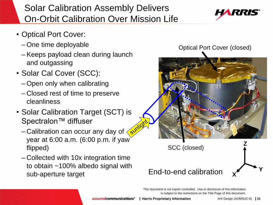
Solar Calibration Assembly Delivers
On-Orbit Calibration Over Mission Life
• Optical Port Cover:
– One time deployable
– Keeps payload clean during launch
and outgassing
• Solar Cal Cover (SCC):
– Open only when calibrating
– Closed rest of time to preserve
cleanliness
• Solar Calibration Target (SCT) is
Spectralon™ diffuser
– Calibration can occur any day of
year at 6:00 a.m. (6:00 p.m. if yaw
flipped)
– Collected with 10x integration time
to obtain ~100% albedo signal with
sub-aperture target
Z
Y X
SCC (closed)
Optical Port Cover (closed)
End-to-end calibration

| Harris Proprietary Information | 16 |
This document is not export controlled. Use or disclosure of this information
is subject to the restrictions on the Title Page of this document.
AHI Design (AOMSUC-6) | 16
Solar Calibration Subsystem Built, Tested,
and Qualified for ABI
Diffuser
Optical Port Sunshield Assembly
Stray Light Baffles Solar Calibration Port
Design optimized
for minimum
calibration uncertainty
| Harris Proprietary Information | 17 |
This document is not export controlled. Use or disclosure of this information
is subject to the restrictions on the Title Page of this document.
AHI Design (AOMSUC-6) | 17
Electronic Calibration (ECAL) Verifies
Linearity Throughout Mission
End-to-end test collects radiance from on-board targets
(ICT & SCT) while varying integration time multiplicative factor
• 0.5x to 16.5x in 33 steps of 0.5x
• 0.0625x to 2x in 32 steps of 0.0625x (1/16th)
• 1x to 22x in 22 steps of 1x
Integration time proportional to integrated photons
• More easily controlled than injected voltage levels and tests much
more of analog-to-digital signal processing chain
All integration times collected with all targets and all channels
• First set typically used for λ < 3 μm (bands 1-6) when viewing SCT
– Nominal SCT observation performed with integration factor of 10x
• Second set typically used for λ > 5 μm (bands 8-16) when viewing ICT
• Third set typically used for λ = 3.9 μm (band 7) when viewing ICT
ECAL can also be used when observing space or any other
external scene
| Harris Proprietary Information | 18 |
This document is not export controlled. Use or disclosure of this information
is subject to the restrictions on the Title Page of this document.
AHI Design (AOMSUC-6) | 18
Operational Calibration Routinely
Performed
Spacelook collected at least every 30 s
• First data collected in every operational timeline
• Automatically collected as part of every Full Disk swath
– Either at start or end, depending upon scan direction and location of sun
– Can be autonomously collected on side opposite the sun
• Explicitly scheduled in timeline as needed
Blackbody (ICT) observed at start of each timeline
• Hence, collected every 10 minutes
• Ensures all imagery collected during timeline can be radiometrically
calibrated
Solar calibration scheduled when needed
• Primary cause of VNIR calibration drift is throughput loss due to
molecular contamination and radiation

| Harris Proprietary Information | 19 |
This document is not export controlled. Use or disclosure of this information
is subject to the restrictions on the Title Page of this document.
AHI Design (AOMSUC-6) | 19
Agenda
AHI Design
Calibration Targets
Operational Flexibility
Resampling
Summary
Himawari-8 True Color (RGB) Image courtesy of JMA AHI-8 (photo by Harris)

| Harris Proprietary Information | 20 |
This document is not export controlled. Use or disclosure of this information
is subject to the restrictions on the Title Page of this document.
AHI Design (AOMSUC-6) | 20
On-Orbit Operations:
Raster Scan vs. Boustrophedonic
Raster scan results in higher quality images
• Constant time interval across swath boundary
Only possible because of Harris’ advanced scanner
• Smooth, fast slews at low power with little spacecraft disturbance
Himawari-7 Imager
Boustrophedonic
(“as the ox plows”)
AHI
Default = Raster Scan
Capable of boustrophedonic

| Harris Proprietary Information | 21 |
This document is not export controlled. Use or disclosure of this information
is subject to the restrictions on the Title Page of this document.
AHI Design (AOMSUC-6) | 21
Harris’ ABI-Class Imagers Offer Unique
Scan Flexibility
NS swath & stare support vicarious calibration for GSICS
Angled swaths can compensate for spacecraft yaw
• FPM is not rotated; hence coverage decreases as tilt increases
Northern Hemisphere
Local Area
Extended NH
All scenes and timelines can be updated in orbit
NS Swath Stare Perimeter Angled
CONUS
Typhoon Japan Full Disk
| Harris Proprietary Information | 22 |
This document is not export controlled. Use or disclosure of this information
is subject to the restrictions on the Title Page of this document.
AHI Design (AOMSUC-6) | 22
AHI Image Collection Paradigm Shift:
Swath-based, not Image-based
Pixel Image: calibrated, geolocated, resampled image
• Desired image; serves as start of scene definition process
Scene: commanded area to be observed (e.g. CONUS)
• Ordered set of swaths; need not be contiguous
Swath: sub-area of scene collected in a single scan
• Defined by start and end coordinates
• Straight line at any angle (usually west-to-east, parallel to equator)
Scan: scan maneuver during a swath; constant velocity
Stare: swath with same start and end coordinates
Slew: scan maneuver between swaths
• NS and EW scanners maneuver simultaneously
Timeline: defines what to observe when
• Time sequenced set of scene swaths and durations
| Harris Proprietary Information | 23 |
This document is not export controlled. Use or disclosure of this information
is subject to the restrictions on the Title Page of this document.
AHI Design (AOMSUC-6) | 23
AHI Unique Interleaved Scene Collection
Delivers Full Disk and Regional Scenes
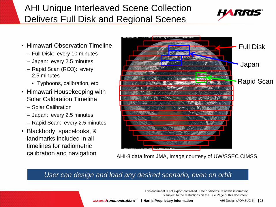
• Himawari Observation Timeline
– Full Disk: every 10 minutes
– Japan: every 2.5 minutes
– Rapid Scan (RO3): every
2.5 minutes
• Typhoons, calibration, etc.
• Himawari Housekeeping with
Solar Calibration Timeline
– Solar Calibration
– Japan: every 2.5 minutes
– Rapid Scan: every 2.5 minutes
• Blackbody, spacelooks, &
landmarks included in all
timelines for radiometric
calibration and navigation
User can design and load any desired scenario, even on orbit
AHI-8 data from JMA, Image courtesy of UW/SSEC CIMSS
Full Disk
Japan
Rapid Scan
| Harris Proprietary Information | 24 |
This document is not export controlled. Use or disclosure of this information
is subject to the restrictions on the Title Page of this document.
AHI Design (AOMSUC-6) | 24
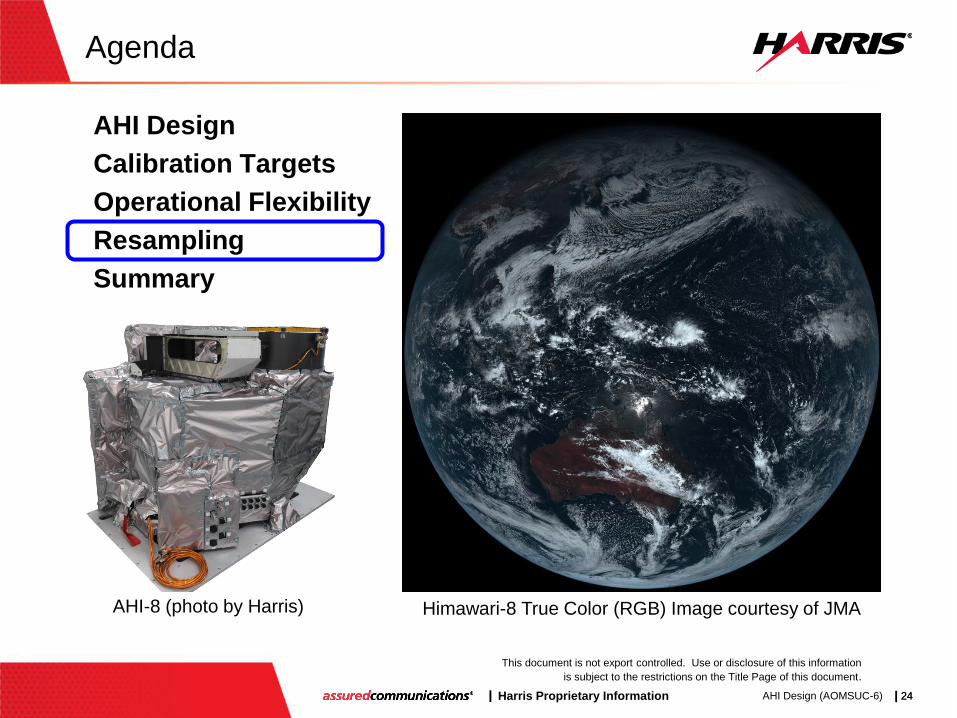
Agenda
AHI Design
Calibration Targets
Operational Flexibility
Resampling
Summary
Himawari-8 True Color (RGB) Image courtesy of JMA AHI-8 (photo by Harris)
| Harris Proprietary Information | 25 |
This document is not export controlled. Use or disclosure of this information
is subject to the restrictions on the Title Page of this document.
AHI Design (AOMSUC-6) | 25
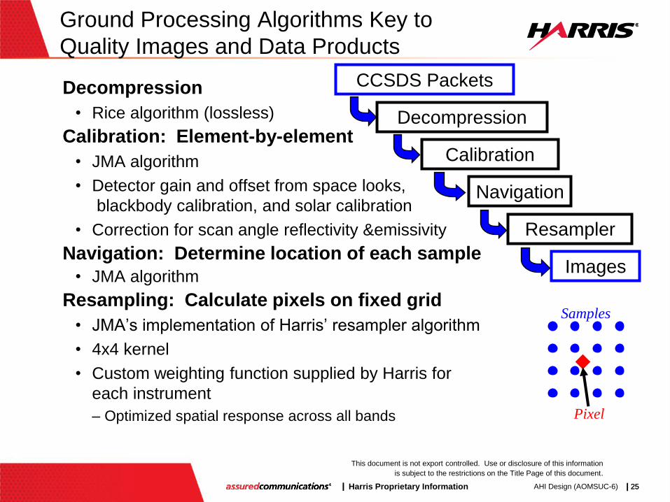
Ground Processing Algorithms Key to
Quality Images and Data Products
Decompression
• Rice algorithm (lossless)
Calibration: Element-by-element
• JMA algorithm
• Detector gain and offset from space looks,
blackbody calibration, and solar calibration
• Correction for scan angle reflectivity &emissivity
Navigation: Determine location of each sample
• JMA algorithm
Resampling: Calculate pixels on fixed grid
• JMA’s implementation of Harris’ resampler algorithm
• 4x4 kernel
• Custom weighting function supplied by Harris for
each instrument
– Optimized spatial response across all bands
CCSDS Packets
Decompression
Calibration
Navigation
Resampler
Images
Samples
Pixel

| Harris Proprietary Information | 26 |
This document is not export controlled. Use or disclosure of this information
is subject to the restrictions on the Title Page of this document.
AHI Design (AOMSUC-6) | 26
AHI Resampler uses 4x4 Kernel
Separable EW & NS
1i
iw
owx ,0
11, wx
22 , wx
33, wx
ASDxx nn 1
Samples
Pixel
4
1
4
1
,
4
1
4
1
i j ji
jii j ji
ww
SwwP
One-dimensional example Ideal relationships
ASD = angular sample distance
Weight Function
Actual formula
All samples used come from the same swath

| Harris Proprietary Information | 27 |
This document is not export controlled. Use or disclosure of this information
is subject to the restrictions on the Title Page of this document.
AHI Design (AOMSUC-6) | 27
Agenda
AHI Design
Calibration Targets
Operational Flexibility
Resampling
Summary
Himawari-8 True Color (RGB) Image courtesy of JMA AHI-8 (photo by Harris)
| Harris Proprietary Information | 28 |
This document is not export controlled. Use or disclosure of this information
is subject to the restrictions on the Title Page of this document.
AHI Design (AOMSUC-6) | 28
Summary
AHI-8 is the first of the next generation geostationary
weather imagers in operation
Provides improved spectral, spatial and temporal resolution
New on-board targets improve radiometric calibration
Paradigm shift in image collection delivers regional and
rapid scan images without impacting Full Disk cadence
• Due to scanner performance and innovative scan algorithm
Operational flexibility provides unique vicarious calibration
capability
Dr. Paul C. Griffith
Harris Space and Intelligence Systems
Appreciation to NOAA, JMA,
MELCO, and UW/SSEC CIMSS
AHI-8: The Future is Now!