advanced ligo project bookdhs/adv-ligo/old/adl-2002k.pdf · advanced ligo project book 1. overview...
TRANSCRIPT
1
Advanced LIGO Project Book
1. Overview
To be done 14jan03 Project Summary (1- 2 pages) Results from Prior Research (annual report version) Acronym directory (or pointer to LIGO standard) Compact Org Chart needed for Lab, Adv LIGO Must communicate that performance achieves the astrophysics requirement Insert costs and schedule Update GEO (esp. sec 21) Print graphics to check on quality Following the initial LIGO scientific observation period, planned for 2003 through 2006, LIGO detector systems will require an upgrade to significantly improve the detection sensitivity. Such staged improvements were a central part of the original LIGO design and program plan1. LIGO consists of conventional facilities and the interferometric detectors. The LIGO facilities (sites, buildings and building systems, masonry slabs, beam tubes and vacuum equipment) have been specified, designed and constructed to accommodate future advanced LIGO detectors. The initial LIGO detectors were designed with technologies available at the initiation of the construction project. This was done with the expectation that they would be replaced with improved systems capable of ultimately performing to the limits defined by the facilities. In parallel with its support of the initial LIGO construction, the National Science Foundation (NSF) initiated support of a program of research and development focused on identifying the technical foundations of future LIGO detectors. At the same time, the LIGO Laboratory2 worked with the interested scientific community to create the LIGO Scientific Collaboration (LSC) that advocates and executes the scientific program with LIGO3.
1 LIGO Project Management Plan, LIGO M950001-C-M (http://www.ligo.caltech.edu/LIGO_web/ligolab/m950001-c.pdf); LIGO Lab documents can be accessed through the LIGO Document Control Center (http://admdbsrv.ligo.caltech.edu/dcc/) 2 LIGO Laboratory Charter, LIGO M010213-01-M (http://www.ligo.caltech.edu/LIGO_web/ligolab/charter.html) 3 http://www.ligo.org/charter.pdf

2
The LSC, which includes the scientific staff of the LIGO Laboratory, has worked to define the scientific objectives of upgrades to LIGO. It has developed a reference design and an enhanced R&D program plan. This development has led to this proposal for construction of the Advanced LIGO upgrade following the initial LIGO scientific observing period. In this Advanced LIGO Project Book, the definition and conceptual program plan for construction of Advanced LIGO are described. It is intended that this Project Book will be developed further and formally maintained as a working baseline definition document for Advanced LIGO.
Comment: Note: removed ‘LIGO Lab’s’
3
2. Reference Design Baseline Definition
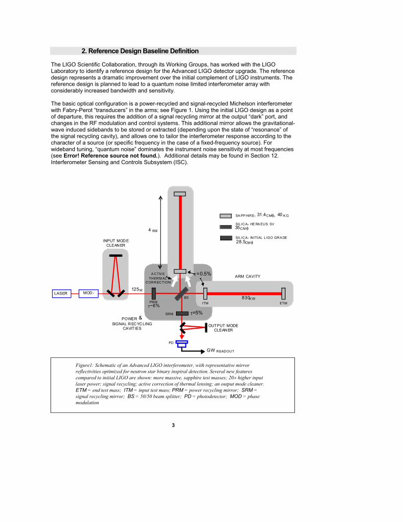
The LIGO Scientific Collaboration, through its Working Groups, has worked with the LIGO Laboratory to identify a reference design for the Advanced LIGO detector upgrade. The reference design represents a dramatic improvement over the initial complement of LIGO instruments. The reference design is planned to lead to a quantum noise limited interferometer array with considerably increased bandwidth and sensitivity. The basic optical configuration is a power-recycled and signal-recycled Michelson interferometer with Fabry-Perot “transducers” in the arms; see Figure 1. Using the initial LIGO design as a point of departure, this requires the addition of a signal recycling mirror at the output “dark” port, and changes in the RF modulation and control systems. This additional mirror allows the gravitational-wave induced sidebands to be stored or extracted (depending upon the state of “resonance” of the signal recycling cavity), and allows one to tailor the interferometer response according to the character of a source (or specific frequency in the case of a fixed-frequency source). For wideband tuning, “quantum noise” dominates the instrument noise sensitivity at most frequencies (see Error! Reference source not found.). Additional details may be found in Section 12. Interferometer Sensing and Controls Subsystem (ISC).
T=0.5%
OUTPUT MODECLEANER
INPUT MODECLEANER
LASER MOD.
T=5%
SA PP HIRE, 31.4CMφ, 40 K G
SIL ICA, HE RA EUS SV 35CM φ
SIL ICA, INITIAL L IGO GRA DE28.5CM φ
125W
830K WPRM
SRM
BS
ITM ETM
GW READOUT
PD
T~6%
A CTIV E
CORRECTIONTHERM AL
4 KM
ARM CAVITY
POWER &SIGNAL RECYCLING
CAVITIES
Figure1: Schematic of an Advanced LIGO interferometer, with representative mirror reflectivities optimized for neutron star binary inspiral detection. Several new features compared to initial LIGO are shown: more massive, sapphire test masses; 20× higher input laser power; signal recycling; active correction of thermal lensing; an output mode cleaner. ETM = end test mass; ITM = input test mass; PRM = power recycling mirror; SRM = signal recycling mirror; BS = 50/50 beam splitter; PD = photodetector; MOD = phase modulation
4
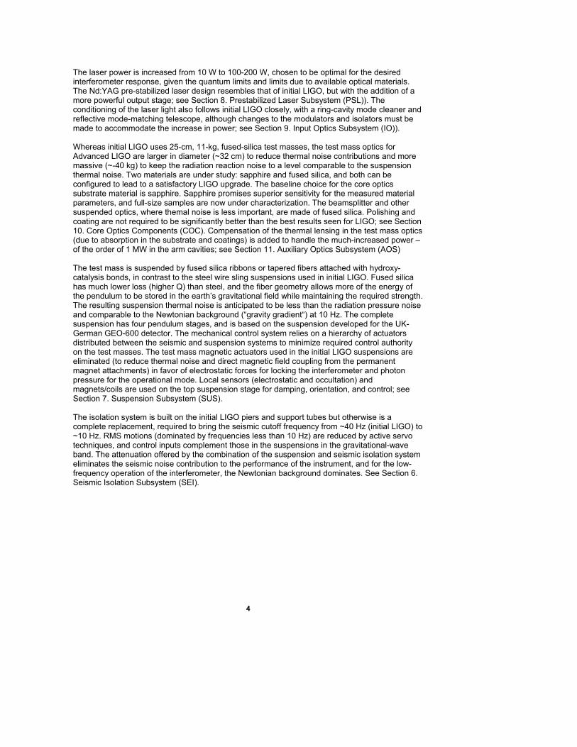
The laser power is increased from 10 W to 100-200 W, chosen to be optimal for the desired interferometer response, given the quantum limits and limits due to available optical materials. The Nd:YAG pre-stabilized laser design resembles that of initial LIGO, but with the addition of a more powerful output stage; see Section 8. Prestabilized Laser Subsystem (PSL)). The conditioning of the laser light also follows initial LIGO closely, with a ring-cavity mode cleaner and reflective mode-matching telescope, although changes to the modulators and isolators must be made to accommodate the increase in power; see Section 9. Input Optics Subsystem (IO)). Whereas initial LIGO uses 25-cm, 11-kg, fused-silica test masses, the test mass optics for Advanced LIGO are larger in diameter (~32 cm) to reduce thermal noise contributions and more massive (~-40 kg) to keep the radiation reaction noise to a level comparable to the suspension thermal noise. Two materials are under study: sapphire and fused silica, and both can be configured to lead to a satisfactory LIGO upgrade. The baseline choice for the core optics substrate material is sapphire. Sapphire promises superior sensitivity for the measured material parameters, and full-size samples are now under characterization. The beamsplitter and other suspended optics, where themal noise is less important, are made of fused silica. Polishing and coating are not required to be significantly better than the best results seen for LIGO; see Section 10. Core Optics Components (COC). Compensation of the thermal lensing in the test mass optics (due to absorption in the substrate and coatings) is added to handle the much-increased power – of the order of 1 MW in the arm cavities; see Section 11. Auxiliary Optics Subsystem (AOS) The test mass is suspended by fused silica ribbons or tapered fibers attached with hydroxy-catalysis bonds, in contrast to the steel wire sling suspensions used in initial LIGO. Fused silica has much lower loss (higher Q) than steel, and the fiber geometry allows more of the energy of the pendulum to be stored in the earth’s gravitational field while maintaining the required strength. The resulting suspension thermal noise is anticipated to be less than the radiation pressure noise and comparable to the Newtonian background (“gravity gradient“) at 10 Hz. The complete suspension has four pendulum stages, and is based on the suspension developed for the UK-German GEO-600 detector. The mechanical control system relies on a hierarchy of actuators distributed between the seismic and suspension systems to minimize required control authority on the test masses. The test mass magnetic actuators used in the initial LIGO suspensions are eliminated (to reduce thermal noise and direct magnetic field coupling from the permanent magnet attachments) in favor of electrostatic forces for locking the interferometer and photon pressure for the operational mode. Local sensors (electrostatic and occultation) and magnets/coils are used on the top suspension stage for damping, orientation, and control; see Section 7. Suspension Subsystem (SUS). The isolation system is built on the initial LIGO piers and support tubes but otherwise is a complete replacement, required to bring the seismic cutoff frequency from ~40 Hz (initial LIGO) to ~10 Hz. RMS motions (dominated by frequencies less than 10 Hz) are reduced by active servo techniques, and control inputs complement those in the suspensions in the gravitational-wave band. The attenuation offered by the combination of the suspension and seismic isolation system eliminates the seismic noise contribution to the performance of the instrument, and for the low-frequency operation of the interferometer, the Newtonian background dominates. See Section 6. Seismic Isolation Subsystem (SEI).
5
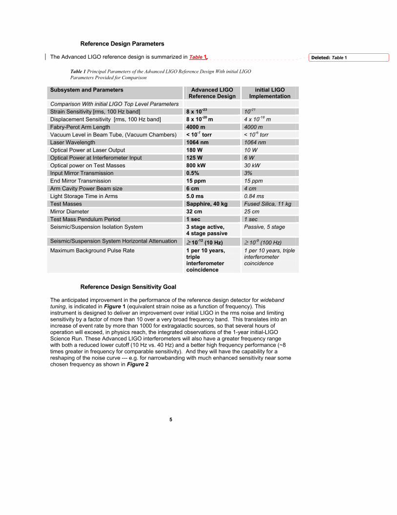
Reference Design Parameters The Advanced LIGO reference design is summarized in Table 1.
Table 1 Principal Parameters of the Advanced LIGO Reference Design With initial LIGO Parameters Provided for Comparison
Subsystem and Parameters Advanced LIGO Reference Design
initial LIGO Implementation
Comparison With initial LIGO Top Level Parameters Strain Sensitivity [rms, 100 Hz band] 8 x 10-23 10-21 Displacement Sensitivity [rms, 100 Hz band] 8 x 10-20 m 4 x 10-18 m Fabry-Perot Arm Length 4000 m 4000 m Vacuum Level in Beam Tube, (Vacuum Chambers) < 10-7 torr < 10-6 torr Laser Wavelength 1064 nm 1064 nm Optical Power at Laser Output 180 W 10 W Optical Power at Interferometer Input 125 W 6 W Optical power on Test Masses 800 kW 30 kW Input Mirror Transmission 0.5% 3% End Mirror Transmission 15 ppm 15 ppm Arm Cavity Power Beam size 6 cm 4 cm Light Storage Time in Arms 5.0 ms 0.84 ms Test Masses Sapphire, 40 kg Fused Silica, 11 kg Mirror Diameter 32 cm 25 cm Test Mass Pendulum Period 1 sec 1 sec Seismic/Suspension Isolation System 3 stage active,
4 stage passive Passive, 5 stage
Seismic/Suspension System Horizontal Attenuation ≥ 10-12 (10 Hz) ≥ 10-9 (100 Hz) Maximum Background Pulse Rate 1 per 10 years,
triple interferometer coincidence
1 per 10 years, triple interferometer coincidence
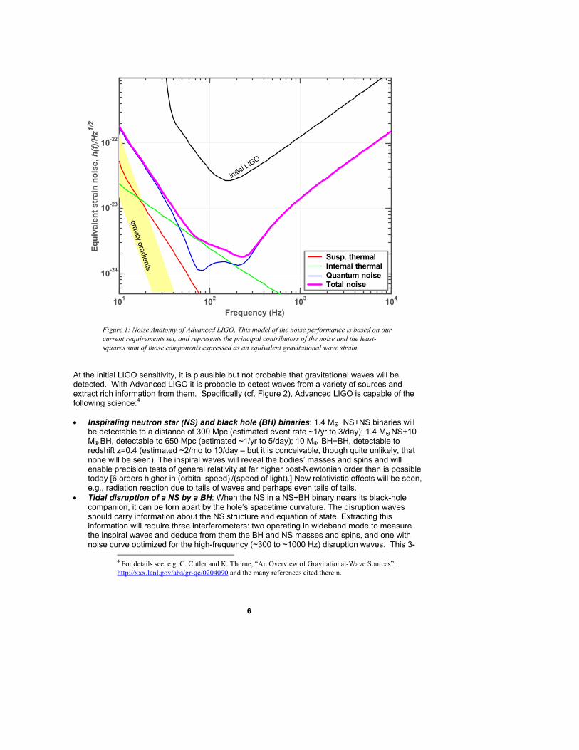
Reference Design Sensitivity Goal The anticipated improvement in the performance of the reference design detector for wideband tuning, is indicated in Figure 1 (equivalent strain noise as a function of frequency). This instrument is designed to deliver an improvement over initial LIGO in the rms noise and limiting sensitivity by a factor of more than 10 over a very broad frequency band. This translates into an increase of event rate by more than 1000 for extragalactic sources, so that several hours of operation will exceed, in physics reach, the integrated observations of the 1-year initial-LIGO Science Run. These Advanced LIGO interferometers will also have a greater frequency range with both a reduced lower cutoff (10 Hz vs. 40 Hz) and a better high frequency performance (~8 times greater in frequency for comparable sensitivity). And they will have the capability for a reshaping of the noise curve --- e.g. for narrowbanding with much enhanced sensitivity near some chosen frequency as shown in Figure 2
Deleted: Table 1
6
101 102 103 104
10-24
10-23
10-22
Frequency (Hz)
Equi
vale
nt s
trai
n no
ise,
h(f)
/Hz1/
2
initial LIGO
gravity gradients
Susp. thermalInternal thermalQuantum noiseTotal noise
Figure 1: Noise Anatomy of Advanced LIGO. This model of the noise performance is based on our current requirements set, and represents the principal contributors of the noise and the least-squares sum of those components expressed as an equivalent gravitational wave strain.
At the initial LIGO sensitivity, it is plausible but not probable that gravitational waves will be detected. With Advanced LIGO it is probable to detect waves from a variety of sources and extract rich information from them. Specifically (cf. Figure 2), Advanced LIGO is capable of the following science:4 • Inspiraling neutron star (NS) and black hole (BH) binaries: 1.4 MO• NS+NS binaries will
be detectable to a distance of 300 Mpc (estimated event rate ~1/yr to 3/day); 1.4 MO• NS+10 MO• BH, detectable to 650 Mpc (estimated ~1/yr to 5/day); 10 MO• BH+BH, detectable to redshift z=0.4 (estimated ~2/mo to 10/day – but it is conceivable, though quite unlikely, that none will be seen). The inspiral waves will reveal the bodies’ masses and spins and will enable precision tests of general relativity at far higher post-Newtonian order than is possible today [6 orders higher in (orbital speed) /(speed of light).] New relativistic effects will be seen, e.g., radiation reaction due to tails of waves and perhaps even tails of tails.
• Tidal disruption of a NS by a BH: When the NS in a NS+BH binary nears its black-hole companion, it can be torn apart by the hole’s spacetime curvature. The disruption waves should carry information about the NS structure and equation of state. Extracting this information will require three interferometers: two operating in wideband mode to measure the inspiral waves and deduce from them the BH and NS masses and spins, and one with noise curve optimized for the high-frequency (~300 to ~1000 Hz) disruption waves. This 3-
4 For details see, e.g. C. Cutler and K. Thorne, “An Overview of Gravitational-Wave Sources”, http://xxx.lanl.gov/abs/gr-qc/0204090 and the many references cited therein.
7
interferometer configuration can also seek NS equation-of-state information by measuring the influence of tidal coupling on the wave spectrum from inspiraling NS+NS binaries.
• BH+BH mergers and ringdowns: When rapidly spinning BH’s collide, they should trigger large-amplitude, nonlinear oscillations of curved spacetime around their merging horizons. Little is known about the dynamics of spacetime under these extreme circumstances; we can learn about it by comparing LIGO’s observations of the emitted waves with supercomputer simulations. Advanced LIGO can detect the merger waves from BH binaries with total mass as great as 2000 MO• , to cosmological redshifts as large as z=2.
• Supernovae: Empirical evidence suggests that neutron stars in type II supernovae receive kicks of magnitude as large as ~1000 km/s. These violent recoils imply the supernova’s collapsing-core trigger may be strongly asymmetric, emitting waves that might be detectable out to the Virgo cluster of galaxies (event rate a few/yr) and perhaps beyond. Even when the collapse is spherical and emits no waves, the collapsed core (proto-neutron star) is predicted to be unstable to convective overturn. The gravitational waves from this convection may be detectable throughout our Galaxy and its orbiting companions, the Magellanic Clouds. By cross correlating the gravitational waves with neutrinos from just one such (very rare) event, we could learn much about the proto-neutron star’s convecting core.
• Gamma-ray bursts: The triggers of gamma ray bursts are thought to be the collapse of massive stellar cores (hypernovae) and/or the merger of NS+NS or NS+BH binaries, all of which emit strong gravitational waves. The next generation of orbiting gamma-ray telescopes will be operational in the time frame of Advanced LIGO, providing astrophysical triggers for LIGO’s searches. With the aid of these triggers, and with predicted enhancements of the gravitational waves along the burst’s beaming direction (toward earth), estimates suggest coincident detections of a few per year. Any such detections would reveal the nature of the gamma-burst trigger. The third interferometer, with noise curve reshaped for better sensitivity at high frequencies, may enable observations of the trigger’s dynamics.
• Spinning neutron stars: The narrowband tunability of the third interferometer will be exploited to search with high sensitivity at high frequencies for gravitational radiation arising from spinning NS’s: known pulsars and Low-Mass X-Ray Binaries (LMXB’s), and unknown pulsars. If (as is plausible) a NS’s accretion torque, in an LMXB, is counterbalanced by its gravitational radiation-reaction torque, then its wave strength is predictable from the observed X-ray flux, and about 10 known LMXB’s would be detectable by Advanced LIGO with narrow-banding but only one (Sco X-1) without. These LMXB’s may serve as “calibration sources” for LIGO. A NS’s crustal shear or internal magnetic field is predicted to be able to support non-axisymmetric ellipticities as large as ε~10-6 or even 10-5. A narrowbanded interferometer could detect a known millisecond pulsar with ε as small as 2x10⁻⁸(1000Hz/f)2(r/10kpc), where f is the wave frequency (most likely twice the spin frequency) and r is the distance. In an all-sky, all-frequency search the sensitivity would be degraded by a factor of a few to ~15.
• Stochastic Waves: The sensitivity improvement of Advanced LIGO, coupled with the decrease in lower frequency cutoff, means that an observational measurement of the stochastic gravitational wave background can be performed with a sensitivity after 1 year of observation of ΩGW~5x10⁻⁹ (ΩGW is the ratio of the stochastic gravity-wave energy density contained in a bandwidth _∆f = f to the total energy density required to close the universe; a flat spectrum is assumed).The sources of such background in the LIGO band are all highly speculative and could be weaker than 5x10⁻⁹ if they exist at all, but also might be stronger and detectable. Some examples are cosmic strings and other topological defects in the structure of spacetime, first-order phase transitions in the states of quantum fields at temperature ~109 K in the very early universe, Goldstone modes of scalar fields that arise in supersymmetric and string theories, coherent excitations of our 3+1 dimensional universe, regarded as a brane in a higher dimensional universe, and the birth of the universe as described by string-motivated ``pre-big-bang’’ cosmology.
• Surprises: We are very ignorant of the gravitational universe – so ignorant that it seems reasonable to expect Advanced LIGO’s observations to bring some big surprises.
8
NS/NS Inspiral 300Mpc; NS/BH Inspiral 650Mpc
BH/BH Inspiral, z=0.4
10 20 50 100 200 500 1000
10- 24
10- 23
10- 22
Initial LIGO
NB Adv LIGO
WB Adv LIGO
10 Mo/10Mo BH/BH inspiral 100Mpc
50Mo/50MoBH/BH Merger, z=2
20Mo/20MoBH/BH Merger, z=1
Ω=10 -9Ω=10 -11
Ω=10 -7
Crab SpindownUpper Limit
Vela SpindownUpper Limit
Sco X-1
LMXBs
Know
n Pu
lsar
ε=10
-6 , r=1
0kpc
ε=10
-7r=
10kp
c
frequency, Hz
BH/BH Inspiral 400Mpc
Merger
Merger
h(f)
andh
s(f)
/Hz1
/2
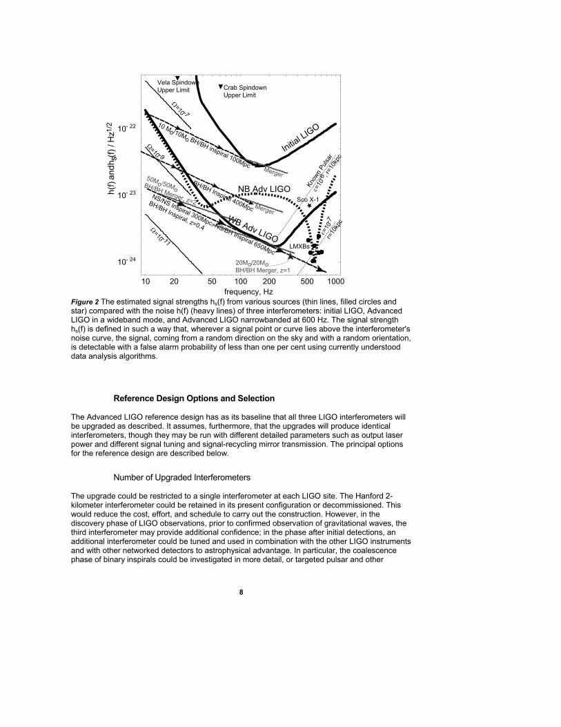
Figure 2 The estimated signal strengths hs(f) from various sources (thin lines, filled circles and star) compared with the noise h(f) (heavy lines) of three interferometers: initial LIGO, Advanced LIGO in a wideband mode, and Advanced LIGO narrowbanded at 600 Hz. The signal strength hs(f) is defined in such a way that, wherever a signal point or curve lies above the interferometer's noise curve, the signal, coming from a random direction on the sky and with a random orientation, is detectable with a false alarm probability of less than one per cent using currently understood data analysis algorithms.
Reference Design Options and Selection The Advanced LIGO reference design has as its baseline that all three LIGO interferometers will be upgraded as described. It assumes, furthermore, that the upgrades will produce identical interferometers, though they may be run with different detailed parameters such as output laser power and different signal tuning and signal-recycling mirror transmission. The principal options for the reference design are described below.
Number of Upgraded Interferometers The upgrade could be restricted to a single interferometer at each LIGO site. The Hanford 2-kilometer interferometer could be retained in its present configuration or decommissioned. This would reduce the cost, effort, and schedule to carry out the construction. However, in the discovery phase of LIGO observations, prior to confirmed observation of gravitational waves, the third interferometer may provide additional confidence; in the phase after initial detections, an additional interferometer could be tuned and used in combination with the other LIGO instruments and with other networked detectors to astrophysical advantage. In particular, the coalescence phase of binary inspirals could be investigated in more detail, or targeted pulsar and other
9
narrowband sources could be observed in the band from 500 Hz – 2 kHz without interrupting observation by the other two instruments. If the upgrade of the third interferometer is dropped from the scope of the Advanced LIGO project, it will significantly reduce the costs and resources required.
2-Kilometer Interferometer Upgraded but Not Converted to 4 Kilometer Length This option could be employed if it is felt that a half-size gravitational wave signal is useful in separating genuine signals and that retaining this feature outweighs the advantages of increasing sensitivity that accompanies an increase in arm length. At this time we choose to increase the arm cavity length in the reference design. If extending the arm cavity is dropped from the scope of this upgrade, the costs and resources required will be modestly reduced from those required in the baseline design.
Simultaneous Implementation of the Upgrade Our baseline plan calls for a staged implementation of the upgrade, in which the Livingston instrument installation is started first, with the installation at Hanford to follow by 8 months. This distributes both fabrication and installation demands over a reasonable period. An alternative would be to engage in a simultaneous installation at the two observatories. This would stress the manpower and the facilities, and would require some duplication of installation equipment. It would potentially reduce the duration during which the pair of LIGO Observatories are “off-line”. Simultaneous implementation may increase the costs, resources and schedule required to complete the Advanced LIGO upgrade.
Test Mass Substrate Material Sapphire is selected as the substrate material in this reference design. It offers significant advantages in reducing thermal noise and in control of thermal distortions on the optics. It requires greater development and carries greater risk than fused silica in crystal growth, cost, optical performance, polishing and coating. Our program will carry fused silica as a fallback option, with some impact on the detector sensitivity, with a well-defined date for confirmation of sapphire or adoption of fused silica for the baseline. If sapphire is dropped from the baseline reference design, the costs, schedule and resources required for Advanced LIGO will likely be unchanged.
Future incremental upgrades to Advanced LIGO
The Reference Design represents a good balance of technical challenges and resulting performance. The intensive R&D effort has demonstrated the robustness of the design. The design is, however, flexible and can accommodate improvements. Some examples that have been explored are as follows:
• Quantum non-demolition techniques: The baseline sensing system “squeezes” the light to a small degree reducing the quantum noise below the naïve limit. Modifications to the interferometer’s input and/or output port fields may allow further reduction of quantum noise’
• Newtonian background cancellation: The changes in mass distribution near the test masses (due to e.g., seismic noise) appears as a low-frequency noise limit. Monitoring this motion with an array of seismometers may allow a regression or cancellation to observe at lower frequencies.
Comment: Needs to communicate that this is possible due to power and flexibility in design more forcefully.
10
• Non-gaussian laser light profiles: The thermal motion of the mirror surface, especially for the thermoelastic noise which dominates in the case of sapphire, has a smaller net effect for larger light beams. Introduction of slightly non-spherical end test masses would lead to non Hermite-Gaussian modes with a larger waist which could reduce this noise source, giving better sensitivity at intermediate frequencies.
• Variable reflectivity signal recycling mirror: The tunability of the interferometer response is limited with a fixed transmission signal recycling mirror. Forming a low-finesse output coupling cavity from a substrate coated on both sides could allow a thermally-tuned output coupler, giving a broad range of instrument response functions.
These are considered as options after observation with the present baseline design for Advanced LIGO. Some may be able to be incorporated into the design shortly after, or coincident with, the commissioning of the baseline. For example, the variable reflectivity signal recycling mirror has been proposed as a Advanced LIGO contribution from the Australian Consortium ACIGA (see next section).
11
3. Program Plan
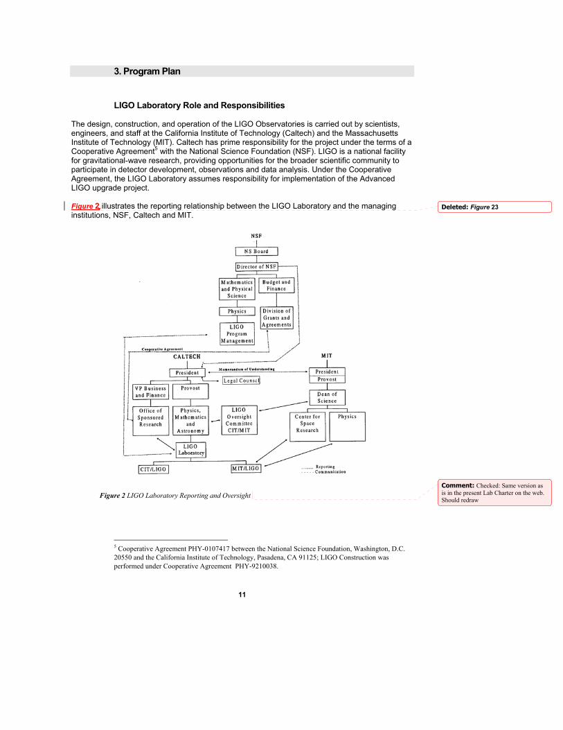
LIGO Laboratory Role and Responsibilities The design, construction, and operation of the LIGO Observatories is carried out by scientists, engineers, and staff at the California Institute of Technology (Caltech) and the Massachusetts Institute of Technology (MIT). Caltech has prime responsibility for the project under the terms of a Cooperative Agreement5 with the National Science Foundation (NSF). LIGO is a national facility for gravitational-wave research, providing opportunities for the broader scientific community to participate in detector development, observations and data analysis. Under the Cooperative Agreement, the LIGO Laboratory assumes responsibility for implementation of the Advanced LIGO upgrade project. Figure 2 illustrates the reporting relationship between the LIGO Laboratory and the managing institutions, NSF, Caltech and MIT.
Figure 2 LIGO Laboratory Reporting and Oversight
5 Cooperative Agreement PHY-0107417 between the National Science Foundation, Washington, D.C. 20550 and the California Institute of Technology, Pasadena, CA 91125; LIGO Construction was performed under Cooperative Agreement PHY-9210038.
Deleted: Figure 23
Comment: Checked: Same version as is in the present Lab Charter on the web. Should redraw
12
The LIGO Laboratory will manage Advanced LIGO construction in the same manner as the original LIGO construction was executed. A project organization will be established within the LIGO Laboratory with a Work Breakdown Structure (WBS) defining the tasks leading to project deliverables. The project organization will parallel the deliverables in the WBS. Task Leaders for each organizational element will be charged with delivering the elements of Advanced LIGO. Prior to initiating the Advanced LIGO project, a Advanced LIGO Project Management Plan will define the details of this organization. Advanced LIGO construction will be a broad effort of the LIGO Scientific Collaboration (LSC), and the WBS and organization chart will reflect the collaborative distribution of the responsibilities.
LIGO Scientific Collaboration Role and Responsibilities The LSC has been established to carry out the LIGO research and development program, to develop priorities, and to enable participation by collaborating groups. It is organized as a separate entity distinct from the LIGO Laboratory. Through its Spokesperson, the LSC communicates with the Laboratory through the Laboratory Directorate. Collaborative work between the LIGO Laboratory and the LIGO Scientific Collaboration is defined in Memoranda of Understanding (MOU)6 between the Laboratory and responsible institutions. Specific tasks are included in Attachments to these MOUs with defined deliverables and periods of performance. A specific MOU and Attachment define membership by an institution in the LSC. Fulfillment of the commitments made by both parties to Attachments is reviewed by periodic progress reports and by revision of the Attachments to define future commitments. Member institutions in the LSC participate in the research and development program leading to enhanced LIGO detectors. These activities are defined in MOUs and Attachments, and, where applicable, through awards from the NSF. Participation by member LSC institutions in the execution of the Advanced LIGO construction project is possible and encouraged. Such participation will be governed by specific Attachments defining each institution’s roles and contributions to the Advanced LIGO project. This management technique has been used successfully in the execution of initial LIGO construction. Participant institutions may receive needed funding through subcontracts with the LIGO Laboratory or through funding from other agencies or foreign sources depending upon the particular role and situation of each institution. The NSF is fully involved in reviewing and approving participation by non-NSF supported institutions. This Project Book represents the definition of the Advanced LIGO project as jointly defined by the LIGO Laboratory and the LSC.
International Collaboration in Advanced LIGO A major role in Advanced LIGO R&D, construction and implementation is proposed for the GEO Project7, a collaboration of United Kingdom and German institutions. The GEO Project has carried out extensive research and development of technologies fundamental to the Advanced LIGO design. They have designed and are commissioning a 600-meter interferometer that will serve, in addition to its intrinsic goals as a gravitational wave detector, as a testbed for Advanced LIGO techniques. They are carrying out important research in suspension of core optics, in reduction of thermal noise, in relevant materials processing, in modeling of instrument performance and sensitivity, in data acquisition and analysis, and in advanced interferometer configurations. Much of this work is directly relevant to defining the Advanced LIGO detector system.
6 http://www.ligo.caltech.edu/LIGO_web/mou/mou.html 7 http://www.geo600.uni-hannover.de/
13
The GEO institutions will lead the definition, design and construction of the suspensions for the Advanced LIGO test mass optics. Based upon the GEO-600 multiple pendulum suspensions, the Advanced LIGO version makes a pivotal contribution to the performance enhancement of LIGO. Similarly, the GEO work in signal tuned interferometer configurations underpins the Advanced LIGO design and performance goal and GEO is undertaking a continuing role in this area. GEO is assuming responsibility to develop and construct the Advanced LIGO Prestabilized Laser systems. GEO has proposed direct support of the Advanced LIGO project to the United Kingdom funding agencies, and plans a request to the German funding agencies8. The GEO role in executing and managing the project will be defined through the bilateral MOU and Attachment process described here. A significant role in Advanced LIGO R&D, construction and implementation is also proposed for the Australian Consortium for Interferometric Gravitational Astronomy9 (ACIGA). ACIGA has an active R&D program on Advanced LIGO techniques including research on the design and development of a 100 W class laser and optical systems compatible with those power levels, control systems for advanced interferometer configurations, and data analysis. ACIGA is constructing a facility at its Gingin site to test the performance of optical systems subjected to high power, a crucial experimental analysis of one of the key Advanced LIGO concepts. Furthermore, ACIGA proposes to expand the capability of Advanced LIGO by leading the development of a variable reflectivity signal recycling mirror, which will allow in-situ manipulation of the instrument’s bandwidth. If this technique is incorporated into for the Advanced LIGO baseline, ACIGA will assume responsibility to develop and construct such mirrors for use on at least one of the Advanced LIGO interferometers. ACIGA is proposing direct support of the Advanced LIGO project to the Australian Research Council. It has already been funded for the test facility construction.
Method of Accomplishment Advanced LIGO is an effort of the entire LIGO Scientific Collaboration. The LIGO Laboratory will manage the project with oversight of all participating institutions. This management will be defined in the MOUs and Attachments for participating institutions outside the LIGO Laboratory. Within the Laboratory, tasks will be assigned to designated Task Leaders and assigned staff reporting to these Task Leaders. Task leaders may come from the greater LIGO Scientific Collaboration, working with a liaison within the Laboratory. For each component, supply or service required to be delivered to Advanced LIGO, the Laboratory will employ either an in-house fabrication or provision of the item or service, or will procure the item or service through a subcontract. It is expected that a substantial fraction of the Advanced LIGO system components will be procured through subcontracts based upon the Advanced LIGO project specifications. The Laboratory and scientific partners will primarily carry out design, contractor supervision, receipt, testing, acceptance, final assembly, installation, integration and commissioning. Formal management of subcontracts will in general be the responsibility of the LIGO Laboratory under the terms of the Cooperative Agreement, though international partners will carry out some subcontracting directly
8 Exploring the Dark Side of the Universe: Proposal for UK Involvement in Advanced LIGO, available at http://www.physics.gla.ac.uk/gwg/AdvLIGO%20Proposal%20Web%20Version.pdf 9 http://www.anu.edu.au/Physics/ACIGA/

14
4. Work Breakdown Structure (WBS)
The LIGO Work Breakdown Structure prior to Advanced LIGO construction is:
1.0 initial LIGO Construction
2.0 LIGO Laboratory Operations
3.0 LIGO Laboratory Advanced R&D
For Advanced LIGO construction, we establish a new top level WBS designation:
4.0 Advanced LIGO Project The definitions of the Advanced LIGO first and second level WBS elements are: 4.0 Advanced LIGO Project (Advanced LIGO) This element includes all costs for removal and securing initial LIGO systems, completion of R&D and design, fabrication of items for the upgrade, and all materials and labor necessary to bring the system to end of the installation phase. It does not include the labor for the commissioning or for the operational phase. 4.1 Facility Modifications (FAC) This element includes modifications and additions to buildings, vacuum systems, and permanent fixed infrastructure that are needed to support the Advanced LIGO detectors. It does not include other facility additions or modifications carried out as normal operations or maintenance tasks. 4.2 Seismic Isolation Subsystem (SEI) This element includes all hardware for the seismic isolation system upgrade. It includes all components of active elements including programmable controls items, and software specific to local control of this subsystem. It does not include general controls for the interferometer, nor shared controls infrastructure. 4.3 Suspension Subsystem (SUS) This element includes all hardware for the suspension subsystem upgrade, including suspension fibers and attachment to the core optics. It includes the intermediate masses. This element provides small suspensions mechanical hardware for other subsystems. It includes all physical hardware for sensing and control (including the electrostatic actuator, but not the photon actuator) of suspended masses. It includes all components of active elements including programmable controls items, and software specific to local control of this subsystem. It does not include general controls for the interferometer, nor shared controls infrastructure. It does not include controls hardware and software specific to other subsystems for which the mechanical suspensions are supplied by this element.
Comment: Phil to review WBS statements
15
4.4 Prestabilized Laser Subsystem (PSL) This element includes all hardware for the prestabilized laser subsystem upgrade (one per interferometer, one spare per observatory, and two prototypes). It includes all components of active elements including programmable controls items, and software specific to local control of this subsystem. It includes the final intensity stabilization system. It does not include general controls for the interferometer, nor shared controls infrastructure. 4.5 Input Optics Subsystem (IO) This element includes all hardware for the input optics subsystem upgrade. Suspension mechanical hardware is provided by the suspension subsystem, and controls are provided by the interferometer sensing and controls subsystem. It includes all other components of active elements including programmable controls items, and software specific to local control of this subsystem. It does not include the shared controls infrastructure. 4.6 Core Optics Components (COC) This element includes all design, purchase of materials, polishing, coating, metrology, cleaning and preparation and transport of the core optics. It includes preparations of the optic for installation in the suspension, but it does not include physical elements attached to the optics required for suspension fiber attachment. 4.7 Auxiliary Optics Subsystem (AOS) This element includes all elements of the output optics subsystem (OO) (all telescopes, output mode cleaner, and miscellaneous steering optics), the stray light control (SLC) subsystem (beam dumps and baffles), the photon actuator for the test mass suspensions (PHO), and the active optics thermal compensation subsystem (AOC). Controls are deisgn by the interferometer sensing and controls subsystem. 4.8 Interferometer Sensing and Controls Subsystem (ISC) This element includes all sensing, signal conditioning and digital conversion electronics, programmable items, computers, and software for the servocontrol of the Advanced LIGO interferometer systems. These include control and coordination of all degrees of freedom of the interferometer up to the interface points with the PSL, AOS, SUS, and SEI subsystems, and sensing and readout of lengths and angles of optical elements. 4.9 Data Acquisition, Diagnostics, Network & Supervisory Control (DAQ) This element includes all the analog and digital signal conditioning electronics, computers, programmable items, networking, software, sensors, actuators and excitation devices for reading Advanced LIGO data and diagnostic data and operating diagnostic systems. Common elements of the supervisory control and human interface for subsystems, and the infrastructure (cable plant, servers, etc.) are also in this subsystem. The element includes all additions and modifications to the LIGO Global Diagnostics System (GDS) and the Physics Environmental Monitor (PEM) system. 4.10 Support Equipment (SUP) This element includes support equipment additions and upgrades needed to install, operate and maintain the Advanced LIGO systems. This element represents equipment, interface systems and support infrastructure that is not subsystem specific.

16
4.11 Advanced LIGO Construction Project Research and Development (R&D) This element includes those R&D activities required to specifically address Advanced LIGO implementation. It is reserved for R&D tasks identified during the fabrication phase and early installation and commissioning. It does not include any tasks included within the LIGO Advanced R&D program currently supported by the NSF and related to Advanced LIGO nor any R&D activities normally carried out within the LIGO Laboratory operations program (WBS 2.0).
17
4.12 Data Analysis and Computing Subsystem (COMP) This element includes all incremental upgrades to data analysis systems and computational infrastructure needed to support the analysis of data from Advanced LIGO. It includes neither software nor computing nor network hardware supported normally by the LIGO Laboratory operations program (WBS 2.0). It does include the LIGO Data Analysis System (LDAS) and the End-to-End Model (E2E) infrastructure development. 4.13 Installation and Commissioning Task (INS) This element includes incremental support of installation and subsystem commissioning of Advanced LIGO above the support included from the LIGO Operations budget (WBS 2.0). It includes all incremental effort to remove and preserve all components of the initial LIGO subsystems not employed in Advanced LIGO. 4.14 Project Management (PM) This element includes all costs of management of the Advanced LIGO construction incremental to the support provided by the LIGO Operations budget (WBS 2.0). These costs will support cost estimating, scheduling, performance definition and measurement, acquisition, quality assurance, ES&H, document control, review and consultation, and system engineering.
18
5. Facility Modifications (FAC)
Overview Advanced LIGO technical requirements will necessitate modifications and upgrades to the LIGO buildings, and vacuum equipment. In addition, the strategy for executing the Advanced LIGO construction will require some facility accommodations. The principal impact on this WBS element is as follows: • It is a program goal to minimize the period during which LIGO is not operating interferometers
for science. For this reason, major subsystems such as the seismic isolation and suspension subsystems should be fully assembled and staged in locations on the LIGO sites ready for installation into the vacuum system as fully assembled and vacuum compatible units. This will require prepared assembly and staging space, materials handling equipment, and softwall clean rooms.
• Increasing the arm cavity length for the Hanford 2-kilometer interferometer to 4 kilometers will
require removing and reinstalling the existing mid-station chambers and replacing them with spool pieces in the original locations. An alternate strategy would be to fabricate additional vacuum tanks for the end stations, and associated spool pieces and preparation. Moving the existing chambers is the choice for the reference design.
• Following the exposure to initial LIGO components and in response to Advanced LIGO
requirements it may be necessary to re-bake the vacuum chambers. The reference design includes support of a re-bake of the major isolatable volumes.
Functional Requirements
Vacuum Equipment All vacuum equipment functional requirements are the same as those in the initial LIGO design except that the vacuum level must be one order of magnitude lower (< 10-7 torr). Additional equipment (chambers, spool pieces, softwall clean rooms) are needed to accommodate additional arm cavity length for one interferometer and the desire for parallel assembly and installation in more chambers and staging areas. A larger diameter spool piece for the IO Mode Cleaner beam path (and possibly for a similar output mode cleaner) is required. The seismic isolation system requirements10 call for the Advanced LIGO subsystems to be compatible with the original LIGO vacuum envelope.
Beam Tube The original end-pumped beam tube system requires no modifications or additions for Advanced LIGO. There is sufficient margin in the present vacuum performance to permit the operation of the more sensitive Advanced LIGO instrument with no changes.
10 LIGO-II Seismic Isolation Design Requirements Document, LIGO-E990303-03-D
19
Conventional Facilities Preassembly of all large Advanced LIGO seismic isolation units prior to installation in the vacuum tanks requires clean onsite staging and assembly space. At both the Hanford and Livingston Observatories there exist suitable staging buildings with appropriate height and basic configuration; portable clean rooms and benches are required. Transporters for delivering fragile systems from the central buildings to the end stations are required.
Concept/Options
Vacuum Equipment Two softwall cleanrooms of the BSC type will be acquired for seismic assembly in the Hanford staging building. Two will be required for Livingston. For each of the interferometers, additional clean rooms will be acquired to support parallel installation in additional chambers to facilitate reducing the duration of Advanced LIGO installation. Four additional spool pieces will be acquired to replace the Hanford mid-station BSC chambers. The chambers will be removed and reinstalled at the end stations. An alternative approach involves acquiring new BSC chambers and leaving the original chambers in place. Vacuum controls will be added at the end stations to accommodate the BSC chambers in their new location. The IO (and potentially the output) Mode Cleaner requires a larger diameter spool piece, ~15m in length, to accommodate the larger mirrors used. The requirement of base pressure for Adv LIGO (< 10-7 torr) is already met by the present system (which is at < 10-8 torr). In the event of long-term contamination or identification of a problematic component, the vacuum equipment isolatable volumes may require baking. We assume three vertex section volume bakes for the reference design with contingency for additional volumes. Some schedule impact is possible if more extensive bakeout is required.
Beam Tube No action planned.
Conventional Facilities The existing staging buildings at both observatories will require additions of flow benches, hoods, and other minor equipment to support clean processing operations. In addition at LHO some retrofit of the HVAC system will be necessary in the Staging Building to meet the cleanliness requirements. HEPA filters and a more powerful motor are needed.
R&D Status/Development Issues There are no development issues or R&D associated with this WBS element.

20
Work Plan Long lead procurements dominate this schedule sensitive WBS element. With funding assumed to commence in FY2005, contracts can be placed promptly for the softwall clean rooms and flow benches. These must be in place prior to commencement of seismic assembly by mid 2006. Similarly, procurement of vacuum equipment for conversion of the Hanford 2-kilometer interferometer should commence in 2005.
21
6. Seismic Isolation Subsystem (SEI)
Overview The seismic isolation subsystem serves to attenuate ground motion in the observation band (above 10 Hz) and also to reduce the motion in the “control band” (frequencies less than 10 Hz). It also provides the capability to align and position the load. Significantly improved seismic isolation will be required for Advanced LIGO to realize the benefit from the reduction in thermal noise due to improvements in the suspension system. The isolation system will be completely replaced, and this offers the opportunity to make a coordinated design including both the controls and the isolation aspects of the interferometer.
Functional Requirements The top-level constraints on the design of the isolation system can be summarized: • Seismic attenuation - The amplitude of the seismic noise at the test mass must be equal to
or less than the thermal noise of the system (10-19 m/√Hz at 10 Hz) for the lowest frequencies where observation is planned. We choose 10 Hz as, at this frequency, the competing noise sources (suspension thermal noise, radiation pressure, Newtonian background) all conspire to establish a presently irreducible sensitivity level roughly a factor of 30 above the limits imposed by the LIGO facilities, and because technical difficulties in suspension design make a lower goal unrealistic.
• The RMS differential motion of the test masses while the interferometer is locked must be
held to a small value (less than 10-14 m) for many reasons: to limit light fluctuations at the antisymmetric port and to limit cross coupling from laser noise sources, as examples. Similarly, the RMS velocity of the test mass must be small enough and the test mass control robust enough that the interferometer can acquire lock This establishes the requirement on the design of the seismic isolation system in the frequency band from 0.1 to 10 Hz.
• The isolation positioning system must have a large enough control range to allow the
interferometer to remain locked for extended periods; our working value is 1 week. • The system must interface with the rest of the LIGO system, including LIGO vacuum
equipment, the adopted suspension design, and system demands on optical layout and control.
A more complete reference on Advanced LIGO seismic isolation requirements is available11.
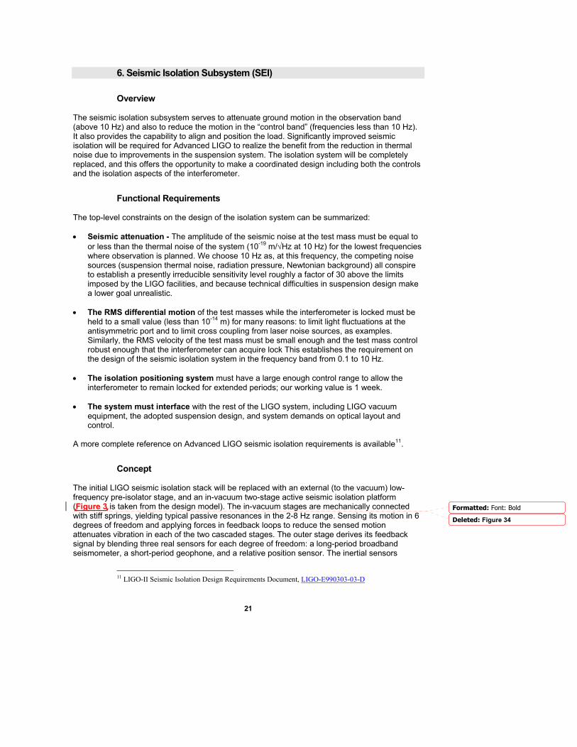
Concept The initial LIGO seismic isolation stack will be replaced with an external (to the vacuum) low-frequency pre-isolator stage, and an in-vacuum two-stage active seismic isolation platform (Figure 3 is taken from the design model). The in-vacuum stages are mechanically connected with stiff springs, yielding typical passive resonances in the 2-8 Hz range. Sensing its motion in 6 degrees of freedom and applying forces in feedback loops to reduce the sensed motion attenuates vibration in each of the two cascaded stages. The outer stage derives its feedback signal by blending three real sensors for each degree of freedom: a long-period broadband seismometer, a short-period geophone, and a relative position sensor. The inertial sensors
11 LIGO-II Seismic Isolation Design Requirements Document, LIGO-E990303-03-D
Formatted: Font: Bold
Deleted: Figure 34
22
(seismometers and geophones) measure the platform's motion with respect to their internal suspended test masses. The position sensor measures displacement with respect to the adjacent stage. The resulting “super-sensor” has adequate signal-to-noise and a simple, resonance-free response from DC to several hundred Hz. The inner stage uses the position sensor and high-sensitivity geophone, and some feed-forward from the outer stage seismometer.
Figure 3 Computer rendering of the conceptual design of the two-stage active isolation system for the test-mass (BSC) vacuum chambers. The outside frame supports the first stage from three trapezoidal blade springs. Three plug-in units carry the sensors and actuators for the unit. The inner second stage is likewise suspended from trapezoidal springs, with the sensor/actuators protruding above the upper surface. The optics are suspended below the inner stage (which forms the interface to the suspension and other isolated parts), and hang below the support structure (HPD).
23
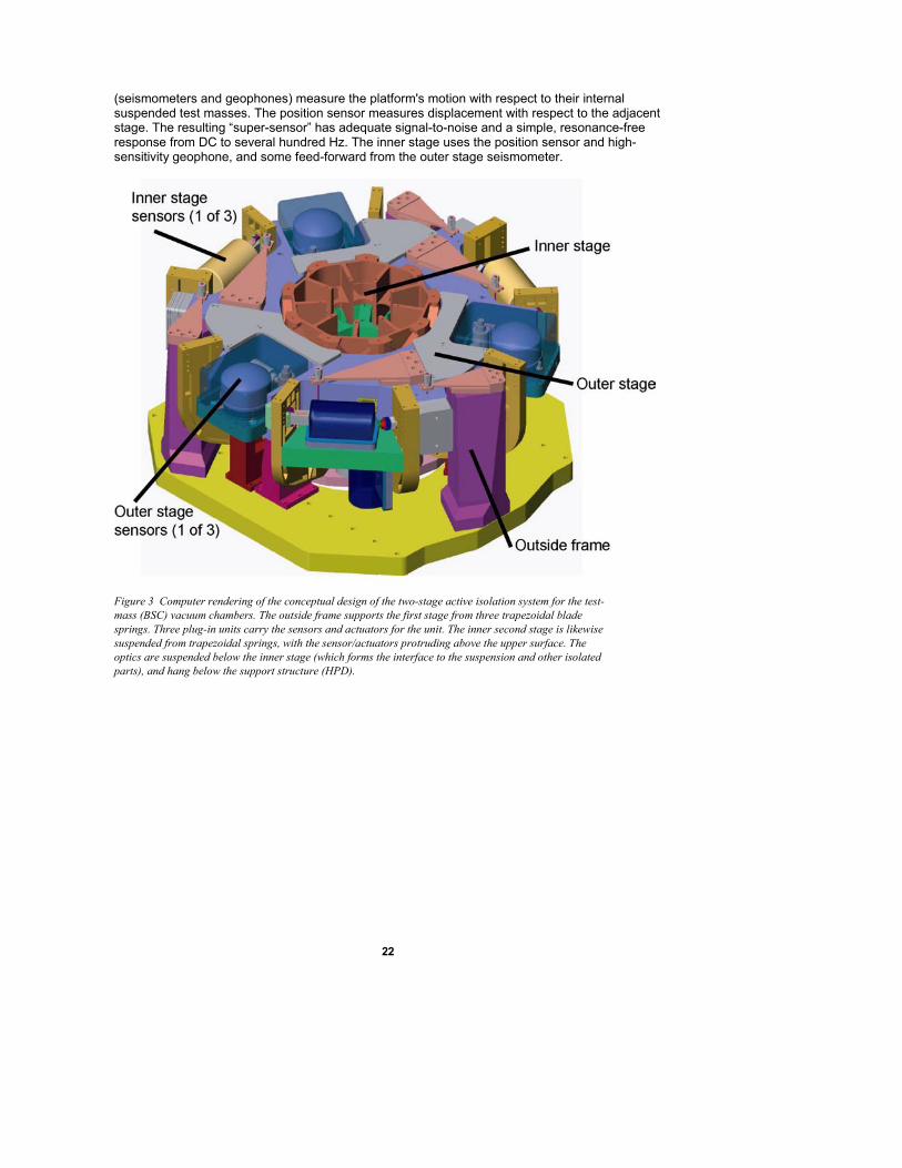
Figure 4: Photograph of the prototype at the Engineering Test Facility (ETF), at Stanford of the in-vacuum seismic isolation system. The trapezoidal springs which support the outer and inner stages can be seen; the cavity at the lower left is one of six (3 outer, 3 inner) cavities which receive a plug-in unit containing sensors and actuators
The outer frame of the isolation system is designed to interface to the existing in-vacuum seismic isolation support system, simplifying the effort required to exchange the present system for the new system. The outer stage is hung from the outer frame using trapezoidal leaf springs to obtain the 2-6 Hz resonances. The inner platform stage is built around a 1.5-m diameter optics table (BSC) or a larger polygonal table (HAM). The mechanical structures are carefully studied to bring the first flexible-body modes well above the ~50 Hz unity gain frequencies of the servo systems. For each suspended optic, the suspension and auxiliary optics (baffles, relay mirrors, etc.) are mounted on an optical table with a regular bolt-hole pattern for flexibility. We will use commercial, off-the-shelf seismometers that are encapsulated in a removable pod. This allows the sensors to be used as delivered, without concerns for vacuum contamination, and allows a simple exchange if difficulties arise. The actuators consist of permanent magnets and coils in a configuration that encloses the flux to reduce stray fields. These components must meet the stringent LIGO contamination requirements. The multiple-input multiple-output servo control system is realized using digital techniques; 16-bit accuracy with ~2 kHz digitization is sufficient. The external pre-isolator is used to position the in-vacuum assembly, with a dynamic range of 1 mm, and with a bandwidth of 2 Hz or greater in all six degrees of freedom. This allows feedforward correction of low-frequency ground noise and sufficient dynamic range for Earth tides and thermal or seasonal drifts. We target approximately a factor of 10 reduction of the ~0.16 Hz microseismic motion from feedforward correction in this stage. For corrections up to the 1-cm clearance at each vacuum feedthrough bellows, large screw adjustments are included in series with each external actuator.

24
The performance of the system, and its initial design, is calculated with a model that includes all solid-body degrees of freedom, and measured or published sensitivity curves (noise and bandwidth) for sensors. It meets the Advanced LIGO requirements with some margin, for both the test-mass (BSC) and auxiliary (HAM) chambers.
25
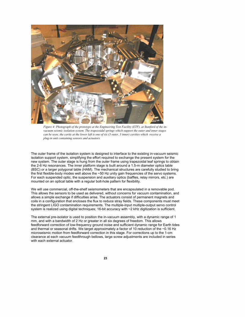
The passive isolation of the suspension system provides the final filtering. A sketch of the system as applied to the test-mass vacuum chambers (BSC) is shown in Figure 5; a similar system is designed for the auxiliary optics chambers (HAM). Further details can be found in the subsystem Design Requirements and Conceptual Design documents12.
Figure 5 Rendering of isolation system installed in the BSC (Test Mass Chambers), with suspension system attached below .The external preisolator provides the interface between the vertical blue piers and the green horizontal support structure. (C. Hardham, Stanford)
.
12 Advanced LIGO Seismic Isolation System Conceptual Design, E010016-00
Deleted: Figure 56
26
R&D Status/Development Issues A first-generation prototype13 of the in-vacuum isolation system has shown performance at low- and high-frequencies comparable to the requirements. Testing of a preliminary version of the external pre-isolator14 is nearing completion and will be installed in Livingston in 2003 as a remedial effort addressing excess local seismic noise. Testing started in December 2002 on a second-generation prototype of the in-vacuum isolation at the Stanford Engineering Test Facility15. Several issues must be addressed. The most significant is identifying the character of the internal mechanical resonances of as-built designs and crafting control laws that meet requirements in this environment. Other issues include minimizing the confusion of tilt with horizontal motion for low-frequency control, the distribution of control authority through the hierarchy, and stability of parameters (for feed-forward and loop gain design). In addition, processors, analog interfaces, and software systems that are compatible with the LIGO standard will be integrated into the subsystem. Materials issues requiring study include the development of contamination-compatible in-vacuum electromagnetic actuators, and creep and yield behavior of structural materials under stress.
Work Plan The present LIGO Cooperative Agreement and existing NSF grants to LSC member institutions will support research, development, and design on this subsystem through full-scale tests carried out in the MIT LASTI testbed. These involve control and noise-performance tests of complete systems for both the test-mass and the auxiliary optics vacuum chambers, as well as their integration with the suspensions (SUS). Advanced LIGO construction will commence with a final design review and with placement of production subcontracts for all seismic subsystem components. Fabricated components must begin arriving at the staging buildings at the two sites in early 2006. Assembly of complete seismic system units in the staging buildings will take place during 2006. Sufficient systems must be completed at both sites to support installation in the interferometer vacuum chambers in mid-2006.
13 R. Abbott, R. Adhikari, G. Allen, S. Cowley, E. Daw, D. DeBra, J. Giaime, G. Hammond, M. Hammond, C. Hardham, J. How, W. Hua, W. Johnson, B. Lantz, K. Mason, R. Mittleman, J. Nichol, S. Richman, J. Rollins, D. Shoemaker, G. Stapfer, and R. Stebbins. Seismic isolation for advanced LIGO. Classical and Quantum Gravity 19(7):1591, 2002. P010027-01-R 14 Initial LIGO Seismic Isolation Upgrade Design Requirements Document, T020033-02-D 15 http://www.ligo.caltech.edu/docs/G/G010193-00.pdf
27
7. Suspension Subsystem (SUS)
Overview The test-mass suspension subsystem must preserve the low intrinsic losses (and thus the low thermal noise) in the fused silica suspension fibers and sapphire test mass material. It must provide actuators for length and angular alignment, and attenuate seismic noise. The Advanced LIGO reference design suspension is similar in design to the GEO 600 multiple pendulum suspensions, with requirements to achieve a seismic wall of ~10 Hz. A variety of suspension designs is needed for the main interferometer and input conditioning optics.
Functional Requirements The suspension forms the interface between the seismic isolation and the suspended optics. It provides seismic isolation and the means to control the orientation and position of the optic. These functions are served while minimally compromising the thermal noise contribution from the test mass mirrors and only introducing a negligible amount of thermal noise from the suspension elements. The optic (which in the case of the main arm cavity mirror serves also as the test mass) is attached to the suspension fiber during the suspension assembly process and becomes part of the suspension assembly. Features on the test mass will be required for attachment and potentially for actuation. The test mass suspension system is mounted (via bolts and/or clamps) to the seismic isolation system by attachment to the SEI optics table. Local signals are generated and fed to actuators to damp solid body motions of the suspension components; in addition, control signals generated by the interferometer sensing/control (ISC) are received and turned into forces on the test mass to obtain and maintain the operational lengths and angular orientation. There are two variants of the test mass suspension: one for the End Test Mass (ETM) which carries potentially non-transmissive actuators behind the optic, and one for the Input Test Mass (ITM) which must leave the input beam free to couple into the Fabry-Perot arm cavity. There are also variants for the beamsplitter, folding mirror, and recycling mirrors; and for the mode cleaner, input matching telescope, and suspended steering mirrors. A multiple-pendulum is the basis. This has two benefits: • it provides a mechanical filter to reduce noise injected by the controllers and the thermal
noise of the lower Q isolation stages above, • it enables a considerable reduction of control forces exerted on the test mass itself. The latter feature will allow the elimination of the magnets attached to the test mass in initial LIGO (which are the largest source of excess dissipation on the test mass), and should allow the test mass to reach a mechanical loss (and thus thermal noise) limited principally by the substrate material. Furthermore, eliminating the magnets reduces a potential source of correlation between the interferometers due to correlated environmental magnetic fields. Thus both technical noise and fundamental thermal noise should be substantially reduced in such a suspension. Multiple simple pendulum stages also improve the seismic isolation of the test mass for horizontal excitation of the pendulum support point; this is a valuable feature, but requires augmentation with vertical isolation to be effective. Vertical seismic noise can enter into the noise budget through a variety of cross-coupling mechanisms, most directly due to the curvature of the earth over the baseline of the interferometer. Simple pendulums have high natural frequencies for
28
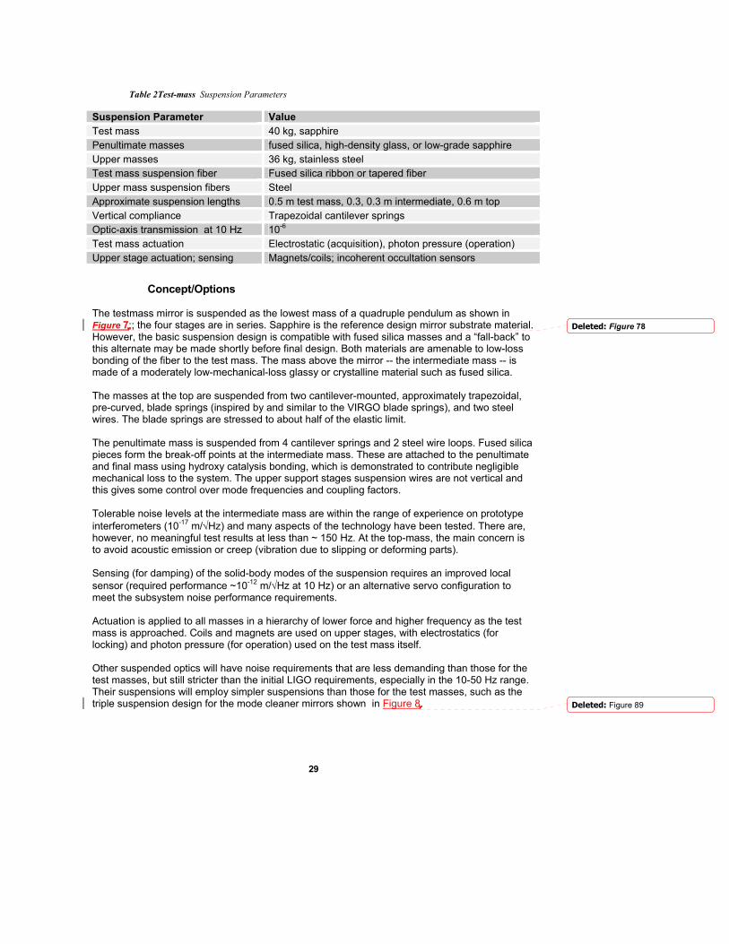
vertical motion. Thus, another key feature of the suspension is the presence of additional vertical compliance in the upper stages of the suspension to provide lower natural frequencies and consequently better isolation. Further detail can be found in the Design Requirements Document.16 Key parameters of the test-mass suspension design are listed in Table 2; other suspensions have requirements relaxed from these values. .
16 Test Mass Suspension Subsystem Design Requirements Document, T010007-00-R
Comment: We need to include these other documents on a CD and/or website to accompany proposal.
Deleted: Table 2
29
Table 2Test-mass Suspension Parameters
Suspension Parameter Value Test mass 40 kg, sapphire Penultimate masses fused silica, high-density glass, or low-grade sapphire Upper masses 36 kg, stainless steel Test mass suspension fiber Fused silica ribbon or tapered fiber Upper mass suspension fibers Steel Approximate suspension lengths 0.5 m test mass, 0.3, 0.3 m intermediate, 0.6 m top Vertical compliance Trapezoidal cantilever springs Optic-axis transmission at 10 Hz 10-6 Test mass actuation Electrostatic (acquisition), photon pressure (operation) Upper stage actuation; sensing Magnets/coils; incoherent occultation sensors
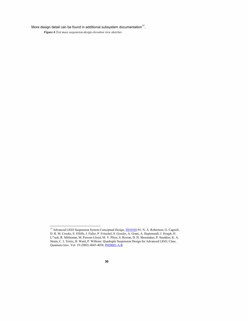
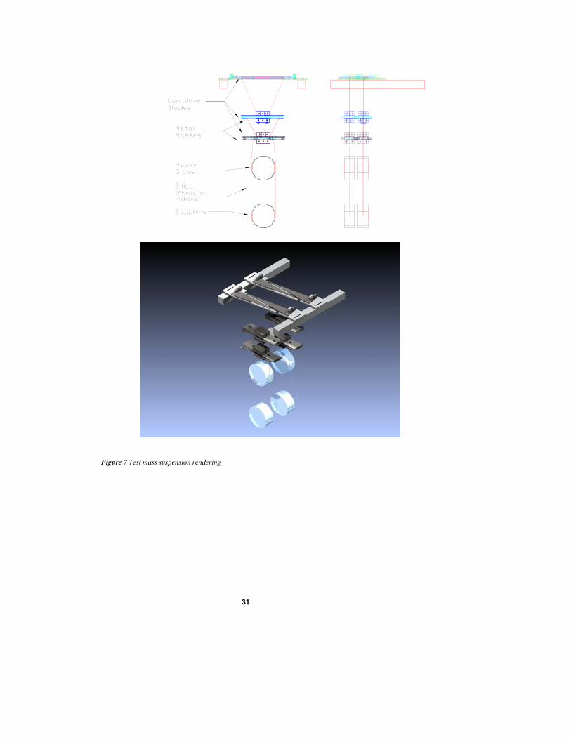
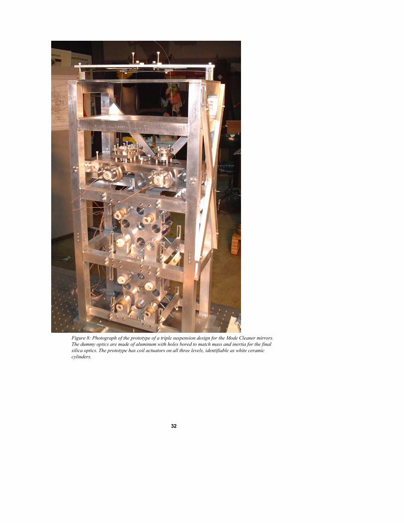
Concept/Options The testmass mirror is suspended as the lowest mass of a quadruple pendulum as shown in Figure 7;; the four stages are in series. Sapphire is the reference design mirror substrate material. However, the basic suspension design is compatible with fused silica masses and a “fall-back” to this alternate may be made shortly before final design. Both materials are amenable to low-loss bonding of the fiber to the test mass. The mass above the mirror -- the intermediate mass -- is made of a moderately low-mechanical-loss glassy or crystalline material such as fused silica. The masses at the top are suspended from two cantilever-mounted, approximately trapezoidal, pre-curved, blade springs (inspired by and similar to the VIRGO blade springs), and two steel wires. The blade springs are stressed to about half of the elastic limit. The penultimate mass is suspended from 4 cantilever springs and 2 steel wire loops. Fused silica pieces form the break-off points at the intermediate mass. These are attached to the penultimate and final mass using hydroxy catalysis bonding, which is demonstrated to contribute negligible mechanical loss to the system. The upper support stages suspension wires are not vertical and this gives some control over mode frequencies and coupling factors. Tolerable noise levels at the intermediate mass are within the range of experience on prototype interferometers (10-17 m/√Hz) and many aspects of the technology have been tested. There are, however, no meaningful test results at less than ~ 150 Hz. At the top-mass, the main concern is to avoid acoustic emission or creep (vibration due to slipping or deforming parts). Sensing (for damping) of the solid-body modes of the suspension requires an improved local sensor (required performance ~10-12 m/√Hz at 10 Hz) or an alternative servo configuration to meet the subsystem noise performance requirements. Actuation is applied to all masses in a hierarchy of lower force and higher frequency as the test mass is approached. Coils and magnets are used on upper stages, with electrostatics (for locking) and photon pressure (for operation) used on the test mass itself. Other suspended optics will have noise requirements that are less demanding than those for the test masses, but still stricter than the initial LIGO requirements, especially in the 10-50 Hz range. Their suspensions will employ simpler suspensions than those for the test masses, such as the triple suspension design for the mode cleaner mirrors shown in Figure 8.
Deleted: Figure 78
Deleted: Figure 89
30
More design detail can be found in additional subsystem documentation17. Figure 6 Test mass suspension design elevation view sketches
17 Advanced LIGO Suspension System Conceptual Design, T010103-01; N. A. Robertson, G. Cagnoli, D. R. M. Crooks, E. Elliffe, J. Faller, P. Fritschel, S. Gossler, A. Grant, A. Heptonstall, J. Hough, H. L\"uck, R. Mittleman, M. Perreur-Lloyd, M. V. Plissi, S. Rowan, D. H. Shoemaker, P. Sneddon, K. A. Strain, C. I. Torrie, H. Ward, P. Willems: Quadruple Suspension Design for Advanced LIGO, Class. Quantum Grav. Vol. 19 (2002) 4043-4058; P020001-A-R
31
Figure 7 Test mass suspension rendering
32
Figure 8: Photograph of the prototype of a triple suspension design for the Mode Cleaner mirrors. The dummy optics are made of aluminum with holes bored to match mass and inertia for the final silica optics. The prototype has coil actuators on all three levels, identifiable as white ceramic cylinders.
33
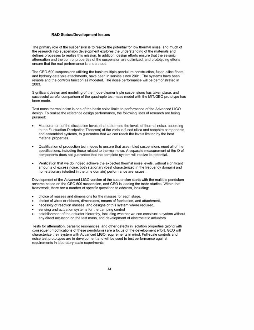
R&D Status/Development Issues The primary role of the suspension is to realize the potential for low thermal noise, and much of the research into suspension development explores the understanding of the materials and defines processes to realize this mission. In addition, design efforts ensure that the seismic attenuation and the control properties of the suspension are optimized, and prototyping efforts ensure that the real performance is understood. The GEO-600 suspensions utilizing the basic multiple-pendulum construction, fused-silica fibers, and hydroxy-catalysis attachments, have been in service since 2001. The systems have been reliable and the controls function as modeled. The noise performance will be demonstrated in 2003. Significant design and modeling of the mode-cleaner triple suspensions has taken place, and successful careful comparison of the quadruple test-mass model with the MIT/GEO prototype has been made. Test mass thermal noise is one of the basic noise limits to performance of the Advanced LIGO design. To realize the reference design performance, the following lines of research are being pursued: • Measurement of the dissipation levels (that determine the levels of thermal noise, according
to the Fluctuation-Dissipation Theorem) of the various fused silica and sapphire components and assembled systems, to guarantee that we can reach the levels limited by the best material properties.
• Qualification of production techniques to ensure that assembled suspensions meet all of the
specifications, including those related to thermal noise. A separate measurement of the Q of components does not guarantee that the complete system will realize its potential.
• Verification that we do indeed achieve the expected thermal noise levels, without significant
amounts of excess noise; both stationary (best characterized in the frequency domain) and non-stationary (studied in the time domain) performance are issues.
Development of the Advanced LIGO version of the suspension starts with the multiple pendulum scheme based on the GEO 600 suspension, and GEO is leading the trade studies. Within that framework, there are a number of specific questions to address, including: • choice of masses and dimensions for the masses for each stage, • choice of wires or ribbons, dimensions, means of fabrication, and attachment, • necessity of reaction masses, and designs of this system where required, • sensing and actuation systems for the damping control • establishment of the actuator hierarchy, including whether we can construct a system without
any direct actuation on the test mass, and development of electrostatic actuators Tests for attenuation, parasitic resonances, and other defects in isolation properties (along with consequent modifications of these pendulums) are a focus of the development effort. GEO will characterize their system with Advanced LIGO requirements in mind. Full-scale controls and noise test prototypes are in development and will be used to test performance against requirements in laboratory-scale experiments.
34
Work Plan The R&D program will include work on this subsystem through full scale tests of all principal variants of the suspensions in the MIT LASTI testbed. By the completion of that test, the design will have been carried through the design requirements, preliminary design, and substantially through the final design review. A final LASTI test will serve to verify form, fit and conformance to functional requirements. Advanced LIGO construction will commence with the final design review and with placement of production subcontracts for all suspension subsystem components. Fabricated components must begin arriving at the optics/vacuum preparation facilities at the two sites in early 2007. A consortium of the University of Glasgow, University of Birmingham, and Rutherford Appleton Laboratory has proposed to UK funding sources (PPARC) to supply the test-mass suspensions for Advanced LIGO8. The GEO group at the University of Glasgow is the originator of the design, and is very well positioned to carry through with this effort. Assembly of complete suspension subsystem units in the site facilities will start in 2006. Suspension of the optics in the completed suspension units will be done at the time of final installation. This will require readiness of optics processing and suspension fiber processing systems at each site. Sufficient systems must be completed at both sites to support installation in the interferometer vacuum chambers early in 2007.
35
8. Prestabilized Laser Subsystem (PSL)
Overview The Advanced LIGO PSL will be a conceptual extension of the initial LIGO subsystem, operating at the higher power level necessary to meet the required Advanced LIGO shot noise limited sensitivity. It will incorporate a frequency and amplitude stabilized 180 W laser. The Advanced R&D program related to this subsystem will develop diode laser pumped slab or rod optical gain stages that can be used either in injection locked power oscillators or as a multipass power amplifier.
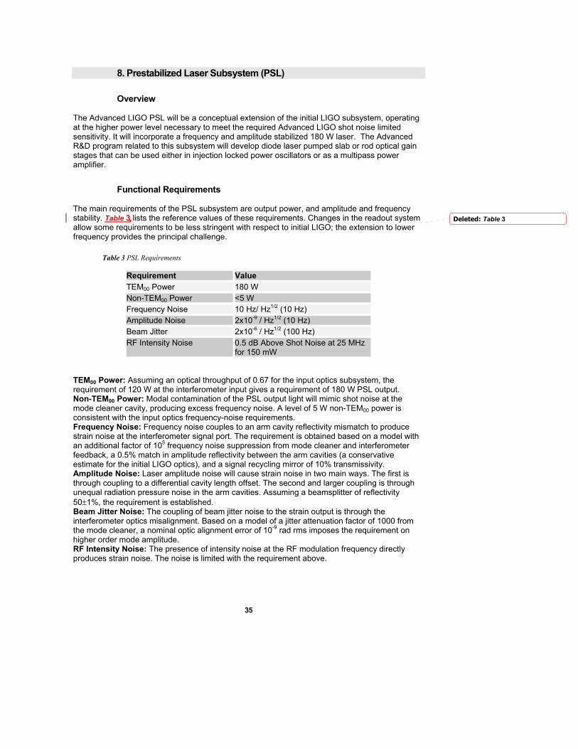
Functional Requirements The main requirements of the PSL subsystem are output power, and amplitude and frequency stability. Table 3 lists the reference values of these requirements. Changes in the readout system allow some requirements to be less stringent with respect to initial LIGO; the extension to lower frequency provides the principal challenge.
Table 3 PSL Requirements
Requirement Value TEM00 Power 180 W Non-TEM00 Power <5 W Frequency Noise 10 Hz/ Hz1/2 (10 Hz) Amplitude Noise 2x10⁻⁹ / Hz1/2 (10 Hz) Beam Jitter 2x10⁻⁶ / Hz1/2 (100 Hz) RF Intensity Noise 0.5 dB Above Shot Noise at 25 MHz
for 150 mW TEM00 Power: Assuming an optical throughput of 0.67 for the input optics subsystem, the requirement of 120 W at the interferometer input gives a requirement of 180 W PSL output. Non-TEM00 Power: Modal contamination of the PSL output light will mimic shot noise at the mode cleaner cavity, producing excess frequency noise. A level of 5 W non-TEM00 power is consistent with the input optics frequency-noise requirements. Frequency Noise: Frequency noise couples to an arm cavity reflectivity mismatch to produce strain noise at the interferometer signal port. The requirement is obtained based on a model with an additional factor of 105 frequency noise suppression from mode cleaner and interferometer feedback, a 0.5% match in amplitude reflectivity between the arm cavities (a conservative estimate for the initial LIGO optics), and a signal recycling mirror of 10% transmissivity. Amplitude Noise: Laser amplitude noise will cause strain noise in two main ways. The first is through coupling to a differential cavity length offset. The second and larger coupling is through unequal radiation pressure noise in the arm cavities. Assuming a beamsplitter of reflectivity 50±1%, the requirement is established. Beam Jitter Noise: The coupling of beam jitter noise to the strain output is through the interferometer optics misalignment. Based on a model of a jitter attenuation factor of 1000 from the mode cleaner, a nominal optic alignment error of 10-9 rad rms imposes the requirement on higher order mode amplitude. RF Intensity Noise: The presence of intensity noise at the RF modulation frequency directly produces strain noise. The noise is limited with the requirement above.
Deleted: Table 3
36
Concept/Options The conceptual design of the Advanced LIGO PSL is similar to that developed for initial LIGO. It will involve the frequency stabilization of a commercially engineered laser with respect to a reference cavity. It will include actuation paths for coupling to interferometer control signals to further stabilize the beam in frequency and in intensity. Three options for the laser design are under study: a slab injection-locked stable-unstable resonator, a rod injection-locked stable resonator, and a multipass power amplifier. The technology will be selected in early 2003. The control system of the Advanced LIGO PSL, including amplitude and frequency servos, will be largely adapted and extended from the initial LIGO design.
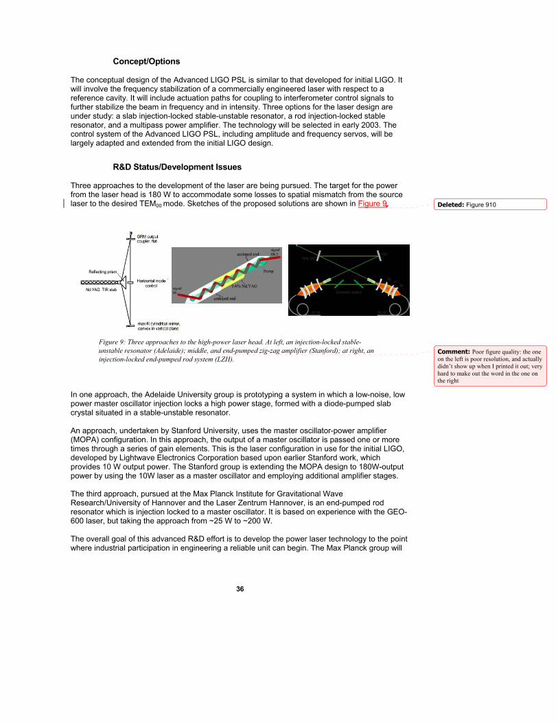
R&D Status/Development Issues Three approaches to the development of the laser are being pursued. The target for the power from the laser head is 180 W to accommodate some losses to spatial mismatch from the source laser to the desired TEM00 mode. Sketches of the proposed solutions are shown in Figure 9.
Figure 9: Three approaches to the high-power laser head. At left, an injection-locked stable-unstable resonator (Adelaide); middle, and end-pumped zig-zag amplifier (Stanford); at right, an injection-locked end-pumped rod system (LZH).
In one approach, the Adelaide University group is prototyping a system in which a low-noise, low power master oscillator injection locks a high power stage, formed with a diode-pumped slab crystal situated in a stable-unstable resonator. An approach, undertaken by Stanford University, uses the master oscillator-power amplifier (MOPA) configuration. In this approach, the output of a master oscillator is passed one or more times through a series of gain elements. This is the laser configuration in use for the initial LIGO, developed by Lightwave Electronics Corporation based upon earlier Stanford work, which provides 10 W output power. The Stanford group is extending the MOPA design to 180W-output power by using the 10W laser as a master oscillator and employing additional amplifier stages. The third approach, pursued at the Max Planck Institute for Gravitational Wave Research/University of Hannover and the Laser Zentrum Hannover, is an end-pumped rod resonator which is injection locked to a master oscillator. It is based on experience with the GEO-600 laser, but taking the approach from ~25 W to ~200 W. The overall goal of this advanced R&D effort is to develop the power laser technology to the point where industrial participation in engineering a reliable unit can begin. The Max Planck group will
Deleted: Figure 910
Comment: Poor figure quality: the one on the left is poor resolution, and actually didn’t show up when I printed it out; very hard to make out the word in the one on the right
37
propose to German funding agencies to supply the laser system for Advanced LIGO, and is leading the downselect and conceptual design effort.
Work Plan The parallel approach to the development of high power lasers is proceeding, with all three groups approaching the intermediate goal of a 100 W laser. Comparative tests of the three laser designs, with participation from LIGO, are planned for early 2003. After the selection is made, an effort with industry, similar to our practice in initial LIGO, will be undertaken to engineer a reliable unit which will meet the LIGO availability goal. Tests of a complete full-power PSL will be made in the LASTI installation in late 2005. The PSL subsystem design work will proceed in parallel with the laser fabrication, so that the complete subsystem will be ready for installation in early 2007.
38
9. Input Optics Subsystem (IO)
Overview The Advanced initial LIGOO subsystem will be an extension of the initial LIGO Input Optics design to the higher specified power and lower noise level of Advanced LIGO. The IO will consist primarily of beam conditioning optics including Faraday Isolators and phase modulators, a triangular input mode cleaner, and an interferometer mode-matching telescope.
Functional Requirements The functions of the IO subsystem are to provide the necessary phase modulation of the input light, to spatially and temporally filter the light on transmission through the mode cleaner, t provide optical isolation as well as distribution of interferometer diagnostic signals, and to mode match the light to the interferometer with a beam-expanding telescope. Table 4 lists the requirements on the output light of the IO II subsystem.
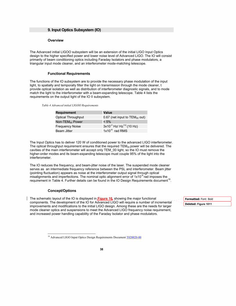
Table 4 Advanced initial LIGOO Requirements
Requirement Value Optical Throughput 0.67 (net input to TEM00 out) Non-TEM00 Power < 5% Frequency Noise 3x10⁻³ Hz/ Hz1/2 (10 Hz) Beam Jitter 1x10⁻⁹ rad RMS
The Input Optics has to deliver 120 W of conditioned power to the advanced LIGO interferometer. The optical throughput requirement ensures that the required TEM00 power will be delivered. The cavities of the main interferometer will accept only TEM_00 light, so the IO must remove the higher-order modes and its beam-expanding telescope must couple 95% of the light into the interferometer. The IO reduces the frequency, and beam-jitter noise of the laser. The suspended mode cleaner serves as an intermediate frequency reference between the PSL and interferometer. Beam jitter (pointing fluctuation) appears as noise at the interferometer output signal through optical misalignments and imperfections. The nominal optic alignment error of 1x10⁻⁹ rad imposes the requirement in Table 4. Further details can be found in the IO Design Requirements document18.
Concept/Options The schematic layout of the IO is displayed in Figure 10, showing the major functional components. The development of the IO for Advanced LIGO will require a number of incremental improvements and modifications to the initial LIGO design. Among these are the needs for larger mode cleaner optics and suspensions to meet the Advanced LIGO frequency noise requirement, and increased power handling capability of the Faraday Isolator and phase modulators.
18 Advanced LIGO Input Optics Design Requirements Document T020020-00
Formatted: Font: Bold
Deleted: Figure 1011
39
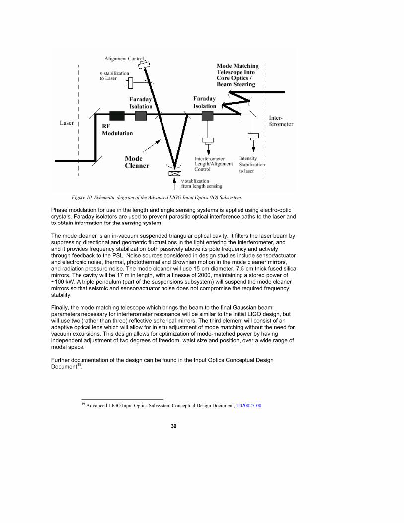
Figure 10 Schematic diagram of the Advanced LIGO Input Optics (IO) Subsystem.
Phase modulation for use in the length and angle sensing systems is applied using electro-optic crystals. Faraday isolators are used to prevent parasitic optical interference paths to the laser and to obtain information for the sensing system. The mode cleaner is an in-vacuum suspended triangular optical cavity. It filters the laser beam by suppressing directional and geometric fluctuations in the light entering the interferometer, and and it provides frequency stabilization both passively above its pole frequency and actively through feedback to the PSL. Noise sources considered in design studies include sensor/actuator and electronic noise, thermal, photothermal and Brownian motion in the mode cleaner mirrors, and radiation pressure noise. The mode cleaner will use 15-cm diameter, 7.5-cm thick fused silica mirrors. The cavity will be 17 m in length, with a finesse of 2000, maintaining a stored power of ~100 kW. A triple pendulum (part of the suspensions subsystem) will suspend the mode cleaner mirrors so that seismic and sensor/actuator noise does not compromise the required frequency stability. Finally, the mode matching telescope which brings the beam to the final Gaussian beam parameters necessary for interferometer resonance will be similar to the initial LIGO design, but will use two (rather than three) reflective spherical mirrors. The third element will consist of an adaptive optical lens which will allow for in situ adjustment of mode matching without the need for vacuum excursions. This design allows for optimization of mode-matched power by having independent adjustment of two degrees of freedom, waist size and position, over a wide range of modal space. Further documentation of the design can be found in the Input Optics Conceptual Design Document19.
19 Advanced LIGO Input Optics Subsystem Conceptual Design Document, T020027-00
40
R&D Status/Development Issues The IO subsystem has completed its Design Requirements and Concept Review and is now in preliminary design. Development of the IO focuses on the need for power handling at the 180 W level and the corresponding development of the Faraday Isolators and phase modulators. For the Faraday Isolator, both wavefront distortion and depolarization effects need to be addressed. A new design20 providing compensation for polarization distortion has shown good isolation up to the maximum test power of 85W. For modulators, we are studying 5 different materials: potassium titanyl phosphate (KTP), potassium titanyl arsenate (KTA), rubidium titanyl arsenate (RTA), rubidium titanyl phosphate (RTP), and lithium niobate (LiNb03). Initial testing suggests that several of these are good candidates, potentially using a compensation approach which resembles that for the Faraday Isolator.
Work Plan Development of high power Faraday Isolators and phase modulators is proceeding under the University of Florida Advanced R&D program, and the subsystem lead role will remain with the University of Florida as for initial LIGO. A complete end-to-end test of the IO will be performed at the LASTI facility in conjunction with the mode cleaner suspension testing and the pre-stabilized laser testing in 2005. Installation will commence in 2007.
20 E. Khazanov, N. Andreev, A. Babin, A. Kiselev, O. Palashov, and D. H. Reitze, “Suppression of Self-Induced Depolarization of High-Power Laser Radiation in Glass-Based Faraday Isolators”, J. Opt. Soc. Am B. 17, 99-102 (2000)
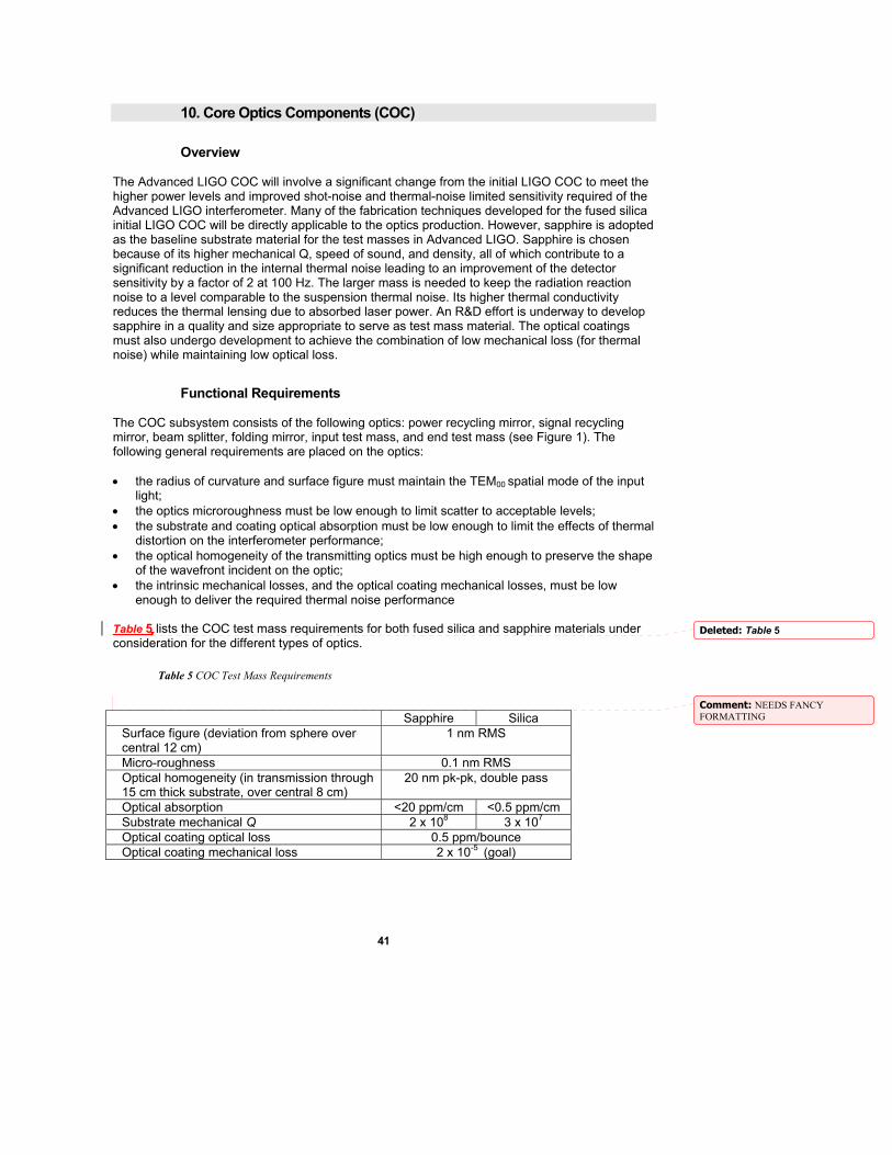
41
10. Core Optics Components (COC)
Overview The Advanced LIGO COC will involve a significant change from the initial LIGO COC to meet the higher power levels and improved shot-noise and thermal-noise limited sensitivity required of the Advanced LIGO interferometer. Many of the fabrication techniques developed for the fused silica initial LIGO COC will be directly applicable to the optics production. However, sapphire is adopted as the baseline substrate material for the test masses in Advanced LIGO. Sapphire is chosen because of its higher mechanical Q, speed of sound, and density, all of which contribute to a significant reduction in the internal thermal noise leading to an improvement of the detector sensitivity by a factor of 2 at 100 Hz. The larger mass is needed to keep the radiation reaction noise to a level comparable to the suspension thermal noise. Its higher thermal conductivity reduces the thermal lensing due to absorbed laser power. An R&D effort is underway to develop sapphire in a quality and size appropriate to serve as test mass material. The optical coatings must also undergo development to achieve the combination of low mechanical loss (for thermal noise) while maintaining low optical loss.
Functional Requirements The COC subsystem consists of the following optics: power recycling mirror, signal recycling mirror, beam splitter, folding mirror, input test mass, and end test mass (see Figure 1). The following general requirements are placed on the optics: • the radius of curvature and surface figure must maintain the TEM00 spatial mode of the input
light; • the optics microroughness must be low enough to limit scatter to acceptable levels; • the substrate and coating optical absorption must be low enough to limit the effects of thermal
distortion on the interferometer performance; • the optical homogeneity of the transmitting optics must be high enough to preserve the shape
of the wavefront incident on the optic; • the intrinsic mechanical losses, and the optical coating mechanical losses, must be low
enough to deliver the required thermal noise performance Table 5 lists the COC test mass requirements for both fused silica and sapphire materials under consideration for the different types of optics.
Table 5 COC Test Mass Requirements
Sapphire Silica Surface figure (deviation from sphere over central 12 cm)
1 nm RMS
Micro-roughness 0.1 nm RMS Optical homogeneity (in transmission through 15 cm thick substrate, over central 8 cm)
20 nm pk-pk, double pass
Optical absorption <20 ppm/cm <0.5 ppm/cm Substrate mechanical Q 2 x 10⁸ 3 x 10⁷ Optical coating optical loss 0.5 ppm/bounce Optical coating mechanical loss 2 x 10⁻⁵ (goal)
Deleted: Table 5
Comment: NEEDS FANCY FORMATTING
42
As the table shows, the figure, roughness and homogeneity requirements are the same for both materials. The absorption requirement is reduced for sapphire because its relatively higher thermal conductivity reduces thermal distortion for a given heat input.
Concept/Options Sapphire is the reference design for the input and end test mass material because of its promise of reduced internal thermal noise and due to better thermal distortion properties. Internal thermal noise is a limit to interferometer sensitivity at the noise minimum near 100 Hz. As insurance against the risks involved in the sapphire development effort, the option of using ultralow optical absorption fused silica for the test masses is being preserved. The final decision to retain sapphire as the critical test mass material is scheduled before production fabrication must begin. Fabrication of fused silica to meet most of the requirements in the above table has already been demonstrated and is not expected to involve research and development; work would be required to ensure acceptable mechanical losses of fused silica in large substrates, although very low losses have been seen in smaller samples. The material properties of fused silica would require significantly more reliance on the thermal compensation system (see AOS). The beam splitter will be made of the best available low absorption fused silica, and the power and signal recycling mirrors of LIGO-I class fused silica. The very long lead time for production of substrates, for polishing, and for coating (for either substrate choice) makes this the critical path item in the Advanced LIGO schedule. Early funding for purchase of the substrates is critical to maintaining the present planned schedule.
R&D Status/Development Issues Sapphire research and development is well underway. We are developing the techniques to grow, polish and coat sapphire to the Advanced LIGO requirements; full size boules (which can be tailored to the 32cm diameter testmass size) of sapphire have been produced and are now undergoing an initial polishing phase to allow characterization of the absorption, birefringence and optical homogeneity and demonstrating suitability for the Advanced LIGO test masses. This R&D resembles that employed in initial LIGO, in which a pathfinder process demonstrated that fused silica optics could be brought to the initial LIGO specifications. Sapphire is a very hard material that requires special polishing techniques including long polishing runs. It must be polished to give a smooth surface both on small scales (microroughness), and large scales (surface figure). Samples have been polished to our requirements. In addition, compensation may be needed for the optical inhomogeneities undergone by the wavefront as it is transmitted through the non-uniform optic. Two approaches to this compensation have been explored: an ion-milling approach (CSIRO) and a computer-controlled spot polishing approach (Goodrich; see Figure 11). In both cases, the results were satisfactory (i.e., correction of inhomogeneities measured in a transmission phase map meet our final requirements for net optical path); the spot-polishing approach can handle full-size pieces and it is our baseline approach.
Comment: STATEMENT OK? Belongs here?
Deleted: Figure 1112
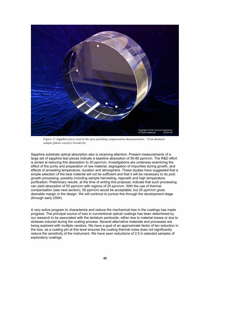
43
Figure 11:Sapphire piece used in the spot-polishing compensation demonstration; 25cm diameter sample (photo courtesy Goodrich).
Sapphire substrate optical absorption also is receiving attention. Present measurements of a large set of sapphire test pieces indicate a baseline absorption of 50-80 ppm/cm. The R&D effort is aimed at reducing this absorption to 20 ppm/cm. Investigations are underway examining the effect of the purity and preparation of raw material, segregation of impurities during growth, and effects of annealing temperature, duration and atmosphere. These studies have suggested that a simple selection of the best material will not be sufficient and that it will be necessary to do post growth processing, possibly including sample harvesting, regrowth and high temperature purification. Preliminary results, at the time of writing this proposal, indicate that such processing can yield absorption of 50 ppm/cm with regions of 20 ppm/cm. With the use of thermal compensation (see next section), 50 ppm/cm would be acceptable, but 20 ppm/cm gives desirable margin in the design. We will continue to pursue this through the development stage (through early 2004). A very active program to characterize and reduce the mechanical loss in the coatings has made progress. The principal source of loss in conventional optical coatings has been determined by our research to be associated with the tantalum pentoxide, either due to material losses or due to stresses induced during the coating process. Several alternative materials and processes are being explored with multiple vendors. We have a goal of an approximate factor of ten reduction in the loss, as a coating phi at this level ensures the coating thermal noise does not significantly reduce the sensitivity of the instrument. We have seen reductions of 2.5 in selected samples of exploratory coatings.

44
Work Plan The sapphire R&D effort will culminate in early 2003, when a decision will be made on whether to proceed with production of sapphire test masses, or instead rely on the fallback plan of ultralow absorption fused silica. Following this selection, fabrication will proceed with the plan for first articles to be available in 2006. The time scale for developing a satisfactory coating, with appropriate optical and mechanical losses, is associated with the commencement of coatings on the production optics at the end of 2005.
45
11. Auxiliary Optics Subsystem (AOS)
Overview The AOS for Advanced LIGO is an extension of this subsystem for initial LIGO, and will accommodate the planned higher laser power and additional signal recycling mirror. The AOS is responsible for transport of interferometer output beams and for stray light control. It includes beam reducing telescopes, and beam dumps and baffles. An additional element of this subsystem is active optics thermal compensation, where compensatory heating of an optic is used to cancel thermal distortion induced by absorbed laser power. It also includes the photon actuator, which uses light pressure to adjust the length of the interferometer arms. AOS also covers the addition of an output mode cleaner.
Functional Requirements The conventional subsystem requirements relate to control of interferometer ghost beams and scattered light, delivery of interferometer pickoff beams to the ISC subsystem, and maintenance of the surface figure of the core optics through active thermal compensation. While the requirements on these elements are somewhat more stringent than for the initial LIGO design, no significant research and development program is required to meet those requirements. There are elements which are new to the Advanced LIGO design for which the requirements will be numerically determined as part of the systems flowdown. Working values for the AOS system are shown in Table 6. • Active Thermal Distortion Compensation: The axisymmetric thermal lens must be
corrected sufficiently to allow the interferometer to “cold start”; the compensation may also be required to correct for small (cm-) scale spatial variations in the substrate absorption.
• Photon Actuator: Forces must be applied to the test mass during the operation of the interferometer to maintain the operating length without compromising the mechanical losses of the system. The photon actuator must have sufficient authority to perform the actuation, without adding noise above a negligible level.
• Output Mode Cleaner: The length sensing system requires that non-TEM00 light power at the antisymmetric output port be reduced substantially to allow a small local-oscillator level to be optimal and thus to maintain the efficiency of the overall shot-noise-limited sensing.
Table 6 Auxiliary Optics Subsystem Requirements
Maximum power of undumped ghost beams
Maximum allowed distortion of pickoff beams
Resolution of active thermal compensation
50 µwatt 1/8 wave 1 nm rms
Concept/Options The AOS conventional elements consist of low-aberration reflective telescopes which are placed in the vacuum system to reduce and relay the output interferometer beams out to the detectors, and baffles of absorptive black glass placed to catch stray and “ghost” beams in the vacuum system. The elements must be contamination free and not introduce problematic mechanical resonances. Because of the increased interferometer stored power, the AOS for Advanced LIGO
Formatted: HTML Body
Formatted: Font: Bold, Do notcheck spelling or grammar
Deleted: ¶Table 6
46
will involve careful attention to control of scattered light, and will require greater baffling and more beam dumps than for initial LIGO. The thermal compensation approach involves adding heat which is complementary to that deposited by the laser beam, using two complementary techniques: a ring heater which deals with circularly symmetric distortions, and a directed laser which allows uneven absorption to be corrected. The frequency-dependent transmission and filtering properties required of the output mode cleaner depend on the ISC readout scheme chosen (DC or RF) and will be determined in an integrated manner with the choice of the readout scheme The photon actuator employs an auxiliary laser which is reflected from the optic to be actuated upon; the laser amplitude is modulated to control the radiation force. The very small forces required can be delivered by lasers of several watts.
R&D Status/Development Issues Development of active optic thermal compensation is proceeding under the LIGO advanced R&D program. A model of the thermal response of the interferometer in a modal basis has been developed21 and used extensively to make predictions for the deformations and of the possible compensation. A prototype has successfully demonstrated thermal compensation, in excellent agreement with the model, using both the ring heater and directed laser techniques22. A detailed characterization of the spatial distribution of absorption in Sapphire is needed to quantify the correct approach for Advanced LIGO; this will be available from the Core Optics Components test articles in early 2003. This will be complemented with a physical optics model using FFT beam propagation techniques, using these phase maps as input. The photon actuator will require a more complete systems model for the dynamic range and frequency response to be precisely defined. The intensity stabilization of the source laser is likely to present the only challenge, but present models do not indicate difficulty with the design. There are two potential designs for the output mode cleaner, dependent on the chosen gravitational wave readout technique. If RF sidebands are used, then the output mode cleaner will be effectively a copy of the input mode cleaner, as it must pass efficiently both the carrier and sidebands. If DC readout is used, the output mode cleaner would be a short, rigid cavity, mounted in one of the output HAM chambers. Both the VIRGO Project and GEO-600 use output mode cleaners in their initial design. We plan to start with a study of their approach and the experience with those systems. The principal design challenges lie in the interface to the Interferometer Sensing and Control. The cavity must be aligned with the nominal TEM00 axis of the interferometer, but the bulk (by several orders of magnitude) of the output power will be in higher-order modes; determining the correct alignment is thus non-trivial. The length control, in particular the lock acquisition sequence, also adds complexity. .
Work Plan
21 R.G.Beausoleil, E. D'Ambrosio, W. Kells, J. Camp, E K.Gustafson, M.M.Fejer: Model of Thermal Wavefront Distortion in Interferometric Gravitational-Wave Detectors I: Thermal Focusing, to appear in JOSA B; http://arxiv.org/abs/gr-qc/0205124 22 Adaptive thermal compensation of test masses in Advanced LIGO, R. Lawrence, M. Zucker, P. Fritschel, P. Marfuta, D. Shoemaker; Class. Quant. Gravity 19 (2002); R. Lawrence, Active Wavefront Correction in Laser Interferometric Gravitational Wave Detectors, MIT Ph.D Thesis, 2002, LIGO-P030001-00-R
47
Work on the active optics thermal compensation is proceeding under the advanced R&D program. A complete prototype thermal compensation system will be tested in the ACIGA Gingin facility in 2003. A prototype photon actuator is being developed with a test on the Caltech 40 Meter Interferometer prototype planned for 2004. The output mode cleaner will be studied using the modeling tools developed for the Mode Cleaner cavity (to which this may bear a strong resemblance) and overall interferometer controls models; a small-scale tabletop prototype will be developed to ensure that the models are complete to support the ISC design schedule (with a Preliminary Design Review in mid-2004). The design process for the beam dumps, baffles, reducing telescopes will resemble that for the initial LIGO design with a planned installation starting in 2007.
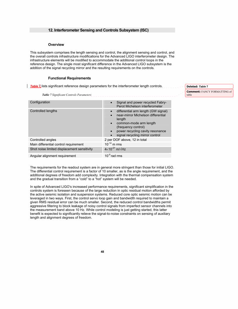
48
12. Interferometer Sensing and Controls Subsystem (ISC)
Overview This subsystem comprises the length sensing and control, the alignment sensing and control, and the overall controls infrastructure modifications for the Advanced LIGO interferometer design. The infrastructure elements will be modified to accommodate the additional control loops in the reference design. The single most significant difference in the Advanced LIGO subsystem is the addition of the signal recycling mirror and the resulting requirements on the controls.
Functional Requirements Table 7 lists significant reference design parameters for the interferometer length controls.
Table 7 Significant Controls Parameters
Configuration • Signal and power recycled Fabry-Perot Michelson interferometer
Controlled lengths • differential arm length (GW signal) • near-mirror Michelson differential
length • common-mode arm length
(frequency control) • power recycling cavity resonance • signal recycling mirror control
Controlled angles 2 per DOF above, 12 in total Main differential control requirement 10-14 m rms Shot noise limited displacement sensitivity 4×10-21 m/√Hz
Angular alignment requirement 10-9 rad rms The requirements for the readout system are in general more stringent than those for initial LIGO. The differential control requirement is a factor of 10 smaller, as is the angle requirement, and the additional degrees of freedom add complexity. Integration with the thermal compensation system and the gradual transition from a “cold” to a “hot” system will be needed. In spite of Advanced LIGO’s increased performance requirements, significant simplification in the controls system is foreseen because of the large reduction in optic residual motion afforded by the active seismic isolation and suspension systems. Reduced core optic seismic motion can be leveraged in two ways. First, the control servo loop gain and bandwidth required to maintain a given RMS residual error can be much smaller. Second, the reduced control bandwidths permit aggressive filtering to block leakage of noisy control signals from imperfect sensor channels into the measurement band above 10 Hz. While control modeling is just getting started, this latter benefit is expected to significantly relieve the signal-to-noise constraints on sensing of auxiliary length and alignment degrees of freedom.
Deleted: Table 7
Comment: FANCY FORMATTING of table
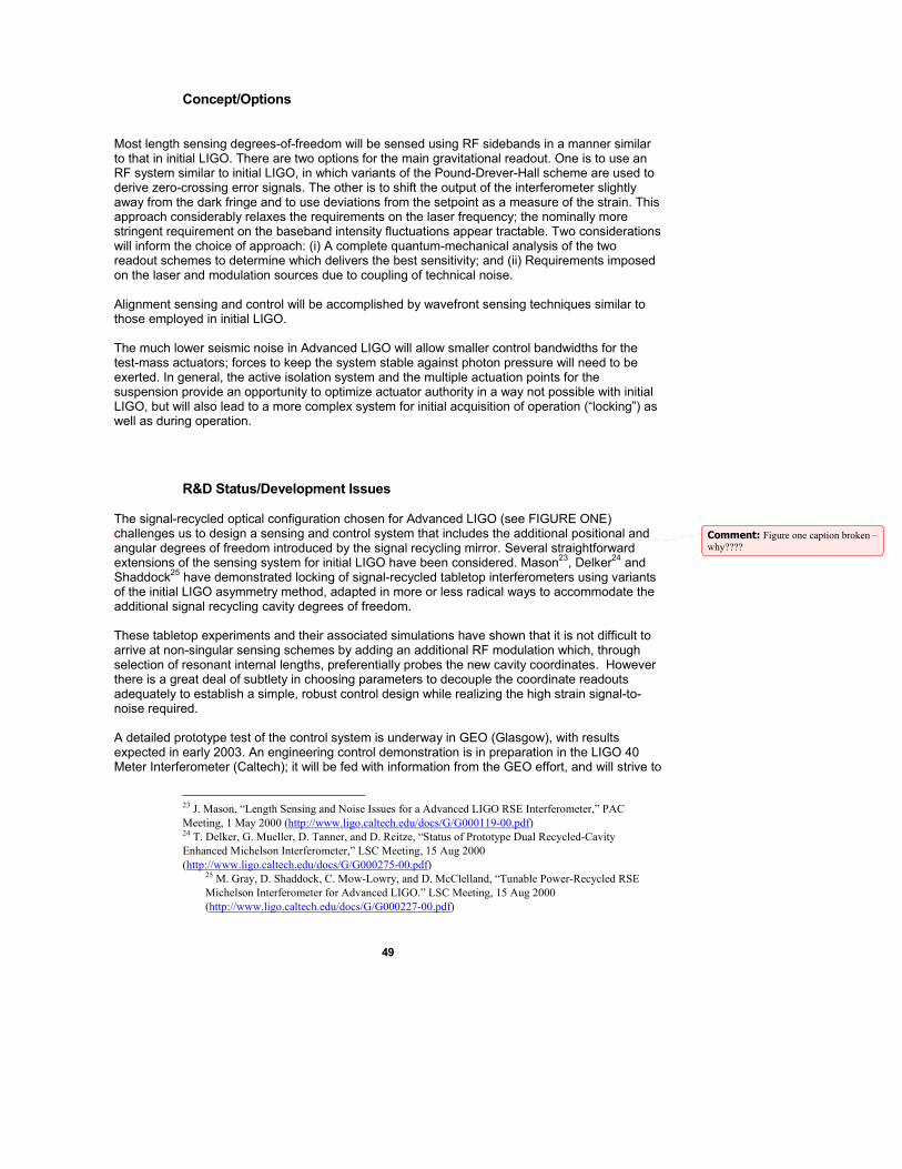
49
Concept/Options Most length sensing degrees-of-freedom will be sensed using RF sidebands in a manner similar to that in initial LIGO. There are two options for the main gravitational readout. One is to use an RF system similar to initial LIGO, in which variants of the Pound-Drever-Hall scheme are used to derive zero-crossing error signals. The other is to shift the output of the interferometer slightly away from the dark fringe and to use deviations from the setpoint as a measure of the strain. This approach considerably relaxes the requirements on the laser frequency; the nominally more stringent requirement on the baseband intensity fluctuations appear tractable. Two considerations will inform the choice of approach: (i) A complete quantum-mechanical analysis of the two readout schemes to determine which delivers the best sensitivity; and (ii) Requirements imposed on the laser and modulation sources due to coupling of technical noise. Alignment sensing and control will be accomplished by wavefront sensing techniques similar to those employed in initial LIGO. The much lower seismic noise in Advanced LIGO will allow smaller control bandwidths for the test-mass actuators; forces to keep the system stable against photon pressure will need to be exerted. In general, the active isolation system and the multiple actuation points for the suspension provide an opportunity to optimize actuator authority in a way not possible with initial LIGO, but will also lead to a more complex system for initial acquisition of operation (“locking”) as well as during operation.
R&D Status/Development Issues The signal-recycled optical configuration chosen for Advanced LIGO (see FIGURE ONE) challenges us to design a sensing and control system that includes the additional positional and angular degrees of freedom introduced by the signal recycling mirror. Several straightforward extensions of the sensing system for initial LIGO have been considered. Mason23, Delker24 and Shaddock25 have demonstrated locking of signal-recycled tabletop interferometers using variants of the initial LIGO asymmetry method, adapted in more or less radical ways to accommodate the additional signal recycling cavity degrees of freedom. These tabletop experiments and their associated simulations have shown that it is not difficult to arrive at non-singular sensing schemes by adding an additional RF modulation which, through selection of resonant internal lengths, preferentially probes the new cavity coordinates. However there is a great deal of subtlety in choosing parameters to decouple the coordinate readouts adequately to establish a simple, robust control design while realizing the high strain signal-to-noise required. A detailed prototype test of the control system is underway in GEO (Glasgow), with results expected in early 2003. An engineering control demonstration is in preparation in the LIGO 40 Meter Interferometer (Caltech); it will be fed with information from the GEO effort, and will strive to
23 J. Mason, “Length Sensing and Noise Issues for a Advanced LIGO RSE Interferometer,” PAC Meeting, 1 May 2000 (http://www.ligo.caltech.edu/docs/G/G000119-00.pdf) 24 T. Delker, G. Mueller, D. Tanner, and D. Reitze, “Status of Prototype Dual Recycled-Cavity Enhanced Michelson Interferometer,” LSC Meeting, 15 Aug 2000 (http://www.ligo.caltech.edu/docs/G/G000275-00.pdf)
25 M. Gray, D. Shaddock, C. Mow-Lowry, and D. McClelland, “Tunable Power-Recycled RSE Michelson Interferometer for Advanced LIGO.” LSC Meeting, 15 Aug 2000 (http://www.ligo.caltech.edu/docs/G/G000227-00.pdf)
Comment: Figure one caption broken – why????
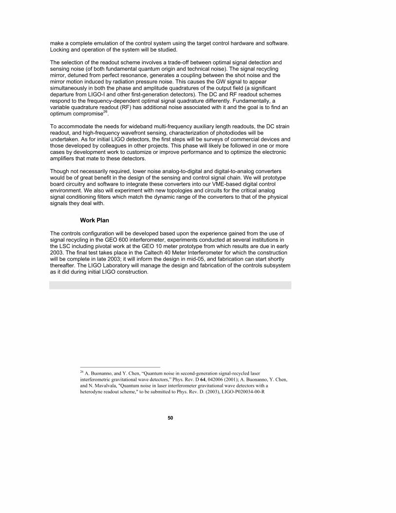
50
make a complete emulation of the control system using the target control hardware and software. Locking and operation of the system will be studied. The selection of the readout scheme involves a trade-off between optimal signal detection and sensing noise (of both fundamental quantum origin and technical noise). The signal recycling mirror, detuned from perfect resonance, generates a coupling between the shot noise and the mirror motion induced by radiation pressure noise. This causes the GW signal to appear simultaneously in both the phase and amplitude quadratures of the output field (a significant departure from LIGO-I and other first-generation detectors). The DC and RF readout schemes respond to the frequency-dependent optimal signal quadrature differently. Fundamentally, a variable quadrature readout (RF) has additional noise associated with it and the goal is to find an optimum compromise26. To accommodate the needs for wideband multi-frequency auxiliary length readouts, the DC strain readout, and high-frequency wavefront sensing, characterization of photodiodes will be undertaken. As for initial LIGO detectors, the first steps will be surveys of commercial devices and those developed by colleagues in other projects. This phase will likely be followed in one or more cases by development work to customize or improve performance and to optimize the electronic amplifiers that mate to these detectors. Though not necessarily required, lower noise analog-to-digital and digital-to-analog converters would be of great benefit in the design of the sensing and control signal chain. We will prototype board circuitry and software to integrate these converters into our VME-based digital control environment. We also will experiment with new topologies and circuits for the critical analog signal conditioning filters which match the dynamic range of the converters to that of the physical signals they deal with.
Work Plan The controls configuration will be developed based upon the experience gained from the use of signal recycling in the GEO 600 interferometer, experiments conducted at several institutions in the LSC including pivotal work at the GEO 10 meter prototype from which results are due in early 2003. The final test takes place in the Caltech 40 Meter Interferometer for which the construction will be complete in late 2003; it will inform the design in mid-05, and fabrication can start shortly thereafter. The LIGO Laboratory will manage the design and fabrication of the controls subsystem as it did during initial LIGO construction.
26 A. Buonanno, and Y. Chen, “Quantum noise in second-generation signal-recycled laser interferometric gravitational wave detectors,” Phys. Rev. D 64, 042006 (2001); A. Buonanno, Y. Chen, and N. Mavalvala, "Quantum noise in laser interferometer gravitational wave detectors with a heterodyne readout scheme," to be submitted to Phys. Rev. D. (2003), LIGO-P020034-00-R
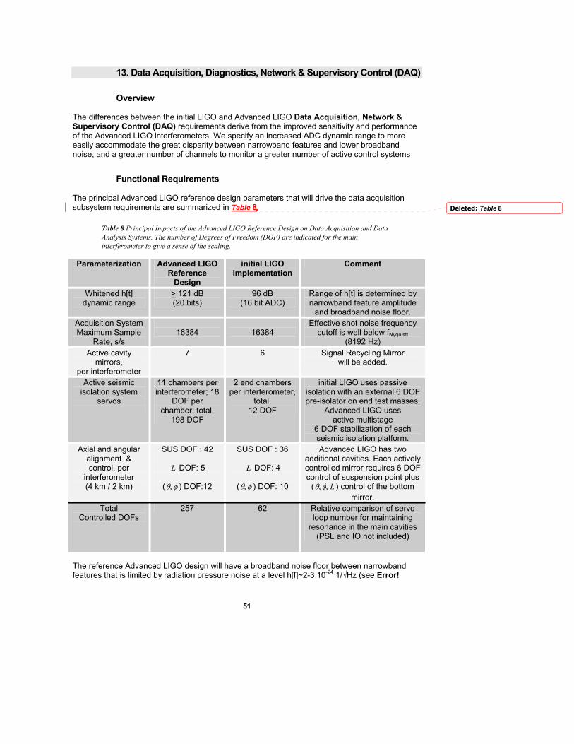
51
13. Data Acquisition, Diagnostics, Network & Supervisory Control (DAQ)
Overview The differences between the initial LIGO and Advanced LIGO Data Acquisition, Network & Supervisory Control (DAQ) requirements derive from the improved sensitivity and performance of the Advanced LIGO interferometers. We specify an increased ADC dynamic range to more easily accommodate the great disparity between narrowband features and lower broadband noise, and a greater number of channels to monitor a greater number of active control systems
Functional Requirements The principal Advanced LIGO reference design parameters that will drive the data acquisition subsystem requirements are summarized in Table 8.
Table 8 Principal Impacts of the Advanced LIGO Reference Design on Data Acquisition and Data Analysis Systems. The number of Degrees of Freedom (DOF) are indicated for the main interferometer to give a sense of the scaling.
Parameterization Advanced LIGO Reference
Design
initial LIGO Implementation
Comment
Whitened h[t] dynamic range
> 121 dB (20 bits)
96 dB (16 bit ADC)
Range of h[t] is determined by narrowband feature amplitude
and broadband noise floor. Acquisition System Maximum Sample
Rate, s/s
16384
16384
Effective shot noise frequency cutoff is well below fNyquistt
(8192 Hz) Active cavity
mirrors, per interferometer
7 6 Signal Recycling Mirror will be added.
Active seismic isolation system
servos
11 chambers per interferometer; 18
DOF per chamber; total,
198 DOF
2 end chambers per interferometer,
total, 12 DOF
initial LIGO uses passive isolation with an external 6 DOF pre-isolator on end test masses;
Advanced LIGO uses active multistage
6 DOF stabilization of each seismic isolation platform.
Axial and angular alignment & control, per
interferometer (4 km / 2 km)
SUS DOF : 42
L DOF: 5
(θ, φ ) DOF:12
SUS DOF : 36
L DOF: 4
(θ, φ ) DOF: 10
Advanced LIGO has two additional cavities. Each actively controlled mirror requires 6 DOF control of suspension point plus
(θ, φ, L ) control of the bottom mirror.
Total Controlled DOFs
257 62 Relative comparison of servo loop number for maintaining
resonance in the main cavities (PSL and IO not included)
The reference Advanced LIGO design will have a broadband noise floor between narrowband features that is limited by radiation pressure noise at a level h[f]~2-3 10-24 1/√Hz (see Error!
Deleted: Table 8
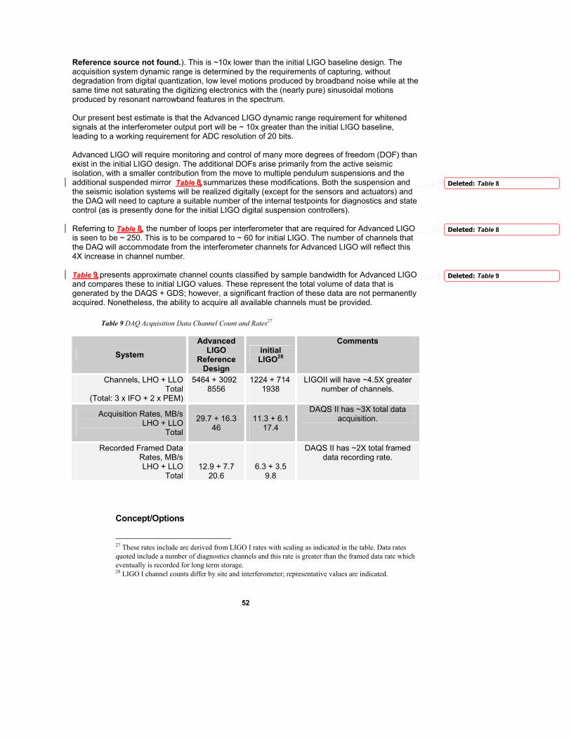
52
Reference source not found.). This is ~10x lower than the initial LIGO baseline design. The acquisition system dynamic range is determined by the requirements of capturing, without degradation from digital quantization, low level motions produced by broadband noise while at the same time not saturating the digitizing electronics with the (nearly pure) sinusoidal motions produced by resonant narrowband features in the spectrum. Our present best estimate is that the Advanced LIGO dynamic range requirement for whitened signals at the interferometer output port will be ~ 10x greater than the initial LIGO baseline, leading to a working requirement for ADC resolution of 20 bits. Advanced LIGO will require monitoring and control of many more degrees of freedom (DOF) than exist in the initial LIGO design. The additional DOFs arise primarily from the active seismic isolation, with a smaller contribution from the move to multiple pendulum suspensions and the additional suspended mirror Table 8 summarizes these modifications. Both the suspension and the seismic isolation systems will be realized digitally (except for the sensors and actuators) and the DAQ will need to capture a suitable number of the internal testpoints for diagnostics and state control (as is presently done for the initial LIGO digital suspension controllers). Referring to Table 8, the number of loops per interferometer that are required for Advanced LIGO is seen to be ~ 250. This is to be compared to ~ 60 for initial LIGO. The number of channels that the DAQ will accommodate from the interferometer channels for Advanced LIGO will reflect this 4X increase in channel number. Table 9 presents approximate channel counts classified by sample bandwidth for Advanced LIGO and compares these to initial LIGO values. These represent the total volume of data that is generated by the DAQS + GDS; however, a significant fraction of these data are not permanently acquired. Nonetheless, the ability to acquire all available channels must be provided.
Table 9 DAQ Acquisition Data Channel Count and Rates27
System Advanced
LIGO Reference
Design
initial LIGO28
Comments
Channels, LHO + LLO Total
(Total: 3 x IFO + 2 x PEM)
5464 + 3092 8556
1224 + 714 1938
LIGOII will have ~4.5X greater number of channels.
Acquisition Rates, MB/s LHO + LLO
Total
29.7 + 16.3
46
11.3 + 6.1
17.4
DAQS II has ~3X total data acquisition.
Recorded Framed Data Rates, MB/s LHO + LLO
Total
12.9 + 7.7 20.6
6.3 + 3.5 9.8
DAQS II has ~2X total framed data recording rate.
Concept/Options
27 These rates include are derived from LIGO I rates with scaling as indicated in the table. Data rates quoted include a number of diagnostics channels and this rate is greater than the framed data rate which eventually is recorded for long term storage. 28 LIGO I channel counts differ by site and interferometer; representative values are indicated.
Deleted: Table 8
Deleted: Table 8
Deleted: Table 9
53
The driving features of the Advanced LIGO hardware design are the increase in channel count and increase in data word length for the main sensing channels. The initial LIGO 16 bit ADCs will be exchanged for newer 32 bit ADCs (note: 20 bits are actually specified). Not all DAQS channels require the greater dynamic range. Moreover, the increase in acquisition bandwidth with double data-word size dictates that only those channels requiring the increased dynamic range should be upgraded. The additional data channels required for the newer seismic isolation and compound suspension systems will require additional ADCs distributed throughout the LVEA and VEA CDS racks. Additional racks will be required and can be placed alongside the present CDS racks within the LVEA and VEAs. In those cases where there is interference with existing hardware, racks will need to be located further away, at places previously set aside for LIGO expansion. Additional cable harnesses needed for new channels will be accommodated within the existing cable trays. The initial LIGO DCUs do not have excess capacity sufficient to accommodate the increase in acquisition rate and will need to be upgraded. The upgrade will be a combination of updating the hardware technology and using a greater number of DCUs. The existing fiber optic infrastructure will accommodate the Advanced LIGO DAQS changes without requiring an upgrade. The DAQ framebuilder and on-line mass storage systems will be upgraded to accommodate the greater data and frame size. The Global Diagnostic System (GDS) will be upgraded to handle ~3X as much real time data as the initial LIGO GDS.
R&D Status/Development Issues Approximately 20 bits of accuracy will be required for Advanced LIGO. At present, ADC technology is not capable of providing full 20-bit ADC precision at output rates of 16384 samples per second. Our experience indicates that the principal limitation is likely the ADC board design that uses the 24-bit ADC chip, and we may need to develop in-house or collaborative solutions with industry to meet our stringent requirements.. Additional performance limitations may also come from the VME format of the boards that initial LIGO uses. The VME bus is a very noisy environment that may limit ADC performance, and we will study alternatives such as VXI for sensitive parts of the design. This will require new solutions to be identified and prototyped. Advanced LIGO thus requires a prototyping program to determine performance of candidate hardware solutions. Much of this type of work will be performed by using the 40 Meter Interferometer at Caltech, which is designed to exercise the hardware and software environment for Advanced LIGO. Similarly, the GDS hardware will need to be scaled for the greater processing and throughput requirements. Parallelization techniques that are being used in the LDAS I design (e.g., passing messages across Beowulf clusters) can be introduced to solve compute-bound (but not I/O bound) data processing problems. It is plausible that hardware technology trends will continue over the next 5 years. Thus, it is likely that the solutions required to support the ~3X increased acquisition rates and data volumes would become commercially available by the time they are needed. We have taken as the point of departure that “Moore’s law” will be a reasonable predictor of the growth in available performance.
Work Plan The first phase will develop a detailed set of requirements for the DAQ upgrade. These will proceed with the development of a Design Requirements Document and a Conceptual Design.
54
Activities that begin in this phase include the development and refinement of a Advanced LIGO model. This will produce a curve of strain sensitivity goal with sufficient details so that issues of dynamic range, etc. can be addressed with simulation to guide the hardware design.As refined design information for new SEI, SUS, LSC, and ASC subsystems becomes available, the channel count estimate and their sampling rates will be improved. The second phase will incorporate results from prototyping Preliminary board layouts for custom components will be developed as part of this stage. The procedures by which the existing plant will be de-integrated and the newer components introduced will be identified. Software development associated with DAQ II modifications of the DAQ I plant and infrastructure will begin. The third phase will culminate in a detailed set of drawings, specifications, and procurement or fabrication plans for the DAQ II equipment. Fabrication will follow, and it is anticipated that this phase will be carried out primarily by the LIGO Laboratory staff as it was during initial LIGO construction.
55
14. Support Equipment (SUP)
Overview Installation of seismic isolation and suspension subsystems in multiple vacuum chambers at both sites will require an increase in basic materials handling equipment. These include additional forklifts, general purpose rigging hardware, personnel lifting devices (of the “Genie-lift” type), and general purpose hand tools suitable for use in an ultra-clean environment. Some of this equipment is also required for assembly of the seismic and suspension units prior to installation.
Functional Requirements All requirements match those used to select similar equipment for initial LIGO construction.
Concept/Options There are no significant options in this element.
R&D Status/Development Issues There are no significant issues in this element.
Work Plan Procurement of the required support equipment must be completed prior to assembly operations in 2006, and installation activities in 2007.
56
15. Advanced LIGO Construction Project Research and Development (R&D)
Overview All identified R&D issues are included in the Advanced R&D program supported by NSF, current LSC activities, or planned development activities supported within the LIGO Laboratory Operations budget (WBS 2.0). In general, the separately funded Advanced R&D program brings all subsystems to the point of the completion of the Design Requirements, the Conceptual Design, and through significant prototyping. The few exceptions are where no R&D is needed, and the requirements and conceptual design are very similar to initial LIGO. At present, there are no activities planned for R&D in the Construction Project phase.
Functional Requirements TBD
Concept/Options TBD
R&D Status/Development Issues TBD
Work Plan TBD
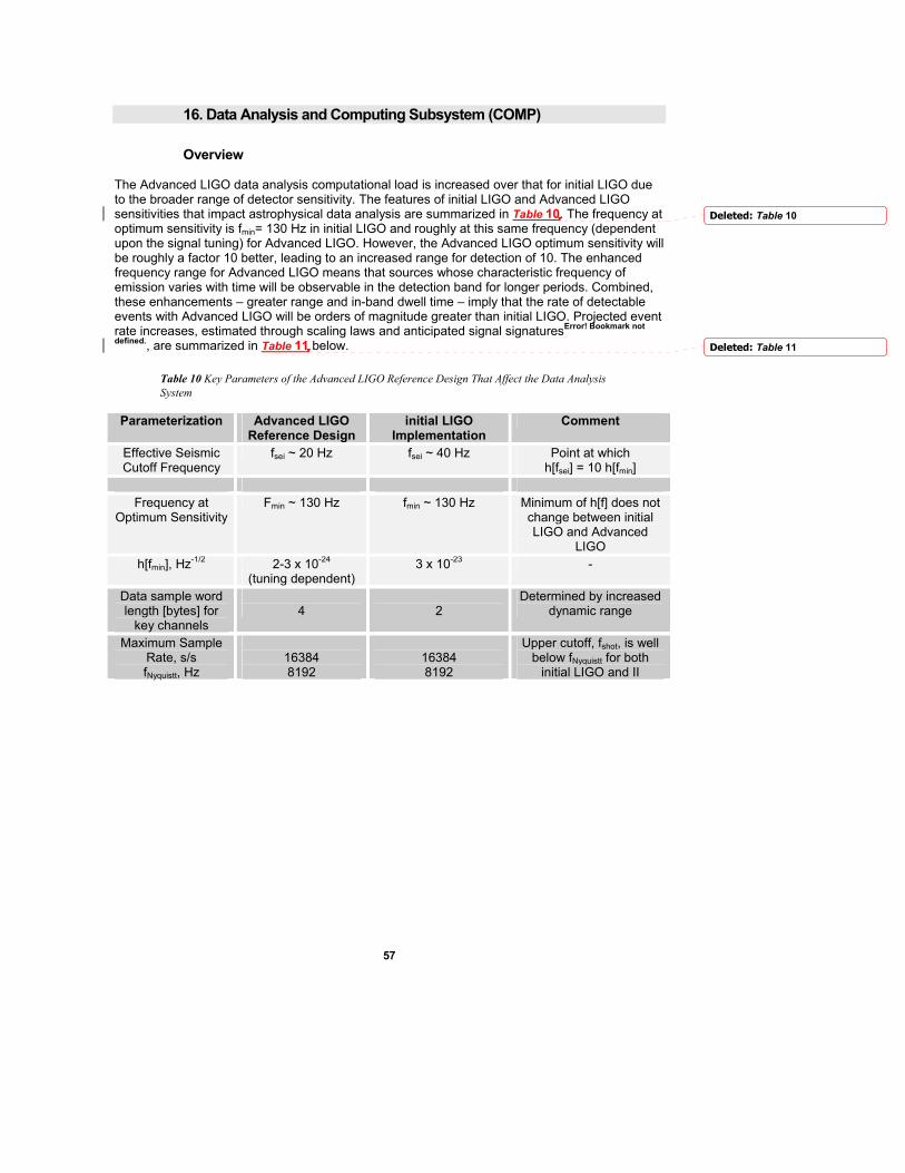
57
16. Data Analysis and Computing Subsystem (COMP)
Overview The Advanced LIGO data analysis computational load is increased over that for initial LIGO due to the broader range of detector sensitivity. The features of initial LIGO and Advanced LIGO sensitivities that impact astrophysical data analysis are summarized in Table 10. The frequency at optimum sensitivity is fmin= 130 Hz in initial LIGO and roughly at this same frequency (dependent upon the signal tuning) for Advanced LIGO. However, the Advanced LIGO optimum sensitivity will be roughly a factor 10 better, leading to an increased range for detection of 10. The enhanced frequency range for Advanced LIGO means that sources whose characteristic frequency of emission varies with time will be observable in the detection band for longer periods. Combined, these enhancements – greater range and in-band dwell time – imply that the rate of detectable events with Advanced LIGO will be orders of magnitude greater than initial LIGO. Projected event rate increases, estimated through scaling laws and anticipated signal signaturesError! Bookmark not
defined., are summarized in Table 11 below.
Table 10 Key Parameters of the Advanced LIGO Reference Design That Affect the Data Analysis System
Parameterization Advanced LIGO Reference Design
initial LIGO Implementation
Comment
Effective Seismic Cutoff Frequency
fsei ~ 20 Hz fsei ~ 40 Hz Point at which h[fsei] = 10 h[fmin]
Frequency at
Optimum Sensitivity Fmin ~ 130 Hz fmin ~ 130 Hz Minimum of h[f] does not
change between initial LIGO and Advanced
LIGO h[fmin], Hz-1/2 2-3 x 10-24
(tuning dependent) 3 x 10-23 -
Data sample word length [bytes] for
key channels
4
2
Determined by increased dynamic range
Maximum Sample Rate, s/s fNyquistt, Hz
16384 8192
16384 8192
Upper cutoff, fshot, is well below fNyquistt for both
initial LIGO and II
Deleted: Table 10
Deleted: Table 11

58
Table 11 Projected Event Rate Increases with Advanced LIGO Relative to initial LIGO.
Source Type Advanced initial LIGOmprovement Relative to initial
LIGO NS + NS
Binary Inspirals
9000 detectable event rate
NS + BH Binary Inspirals
12000X detectable event rate
BH + BH Binary Inspirals
17000X detectable event rate
NS Tidal Disruption During
NS + BH Binary Inspirals
8000X detectable event rate
R-mode Detection in Newborn NS
2700X detectable event rate
BH + BH Mergers 10 MO• + 10 MO• 25 MO• + 25 MO•
100 MO• + 100 MO•
12X 13X 25X
greater SNRs GW Stochastic
Background 10-3 X
Smaller Upper Limit on ΩGW
The impact of exploiting the increased source detection ability on data analysis strategies and the initial LIGO Data Analysis System depends on the source type being considered and will be discussed by source type below. Most presently envisioned search and analysis strategies involve spectral-domain analysis and optimal filtering using template filter banks calculated either from physics principles or parametric representations of phenomenological models. The primary channel that is useful for astrophysics is the instrumental output that is proportional to strain. All the other thousands of channels in initial LIGO and Advanced LIGO are used to validate instrumental behavior. It is also expected that relatively few channels (< 10) will prove useful in producing improved estimates of GW strain. This would be done by removing instrumental cross-channel couplings, etc. either with linear regression techniques in the time domain (Kalman filtering) or in the spectral domain (cross-spectrum correlation). We assume here that signal conditioning will not be a driver for LDAS II upgrades. This is certainly the case for LDAS I and there is no reason to expect this to change. Anticipated sources of gravitational waves may be classified by the frequency vs. time (t-f) behavior of the gravitational radiation waveforms they produce. Transient or burst phenomena have short duration (.1 s – 2s) and have relatively broad frequency content during this short time. The t-f signature of a burst is a vertical “stripe” spanning many frequencies over a narrow time slice. Compact object binary inspirals have durations that will be between ~1 s for the most massive systems to ~1000 s for systems composed of objects at the theoretical limits of NS masses. Their waveform comprises a periodic signal with a time dependent frequency that produces a “chirp” which starts at the low end of the detection band and which crosses the band during the time quoted. Their t-f signature corresponds to a curved (“banana-like”) trajectory such that at each instant in time the waveform has a well-defined and monotonically increasing frequency. Continuous wave periodic sources (i.e., pulsars emitting GW) have very precisely defined frequencies that have secular variations over hours or days. The secular variation
Comment: Check all numbers for consistency with Science Section
59
contains a deterministic component coming from motion of the earth about the Solar System barycenter and possibly other, a priori unknown, components arising from motion of the source in its own orbit. The t-f signature of a CW source is a horizontal “stripe” spanning a narrow frequency range for all times, with the frequency modulated by the Earth’s complicated motion with respect to the source. Finally the stochastic background GW radiation spans many frequencies for all times, and is detected via an excess of the correlation of 2 or more detectors for zero time lag. Corresponding to each of these t-f behaviors there is an optimal search strategy, and each of these has significantly different computational costs.
Functional Requirements
Computational Upgrades For the classes of sources considered (transient “bursts”, compact object inspirals, stochastic backgrounds, and continuous-wave sources), the binary inspirals place the greatest demands on the computational infrastructure. Advanced LIGO will search for compact object binary inspiral events using the same technique that will be employed in initial LIGO: a massive filter bank processing in parallel the same data stream using optimal filtering techniques in the frequency domain. The extension to lower frequencies of observation allowed by Advanced LIGO means that the duration of observation of the inspiral is significantly longer, leading to a concomitant increase in the computing power required. Referring to Table 12, one sees that the baseline initial LIGO can search to 0.7MO• systems, and this involves chirps lasting ~72 s. This increases to ~888 s in Advanced LIGO for 0.5MO• systems. The length of the chirp sets the scale of FFTs that are required for optimal filtering. FFT computational cost scales as ~N log2N. On the other hand, the greater duration of the chirp provides more time to perform the longer calculation. Together a ~12X increase in signal duration corresponds to a ~3X increase in computational cost. Each observatory (Hanford, Livingston) has an on-site Beowulf systems. The Hanford component of LDAS handles two interferometers and is designed to be 2X as capable in terms of CPU FLOPS as the one at Livingston (some components do not scale and are essentially identical at both sites). The quantities appearing in Table 12 correspond to the Hanford site operating with two interferometers. Table 13 lists the main features of the parallel cluster at Hanford Anticipating Moore’s Law for computer hardware development to continue over the next 5 years, the ~ 3X – 4X improvement which will enable Advanced LIGO to search down to 0.5 MO• can be accomplished within the expected technology envelope. Advanced LIGO will upgrade the on-site computational facilities at both observatories to provide capacity to search for low-mass binaries.
Deleted: Table 12
Deleted: Table 12
Deleted: Table 13
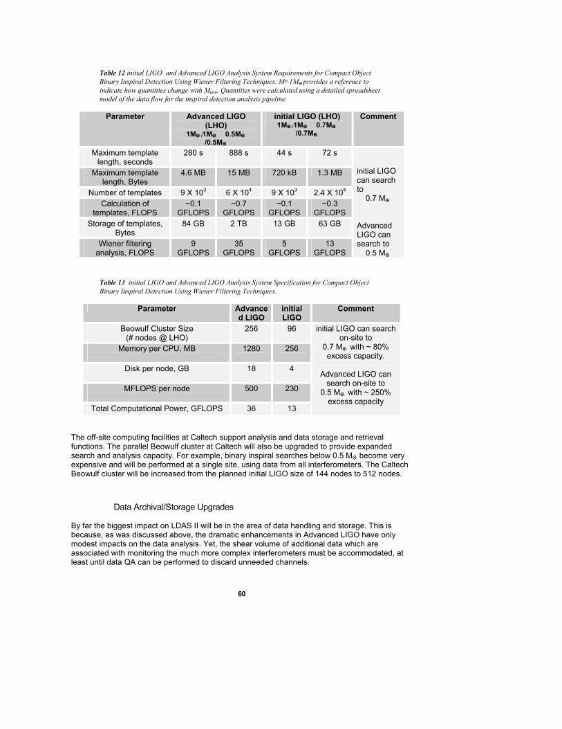
60
Table 12 initial LIGO and Advanced LIGO Analysis System Requirements for Compact Object Binary Inspiral Detection Using Wiener Filtering Techniques. M=1MO• provides a reference to indicate how quantities change with Mmin. Quantities were calculated using a detailed spreadsheet model of the data flow for the inspiral detection analysis pipeline.
Parameter Advanced LIGO (LHO)
1MO• /1MO• 0.5MO• /0.5MO•
initial LIGO (LHO) 1MO• /1MO• 0.7MO•
/0.7MO•
Comment
Maximum template length, seconds
280 s 888 s 44 s 72 s
Maximum template length, Bytes
4.6 MB 15 MB 720 kB 1.3 MB
Number of templates 9 X 10³ 6 X 10⁴ 9 X 10³ 2.4 X 10⁴
Calculation of templates, FLOPS
~0.1 GFLOPS
~0.7 GFLOPS
~0.1 GFLOPS
~0.3 GFLOPS
Storage of templates, Bytes
84 GB 2 TB 13 GB 63 GB
Wiener filtering analysis, FLOPS
9 GFLOPS
35 GFLOPS
5 GFLOPS
13 GFLOPS
initial LIGO can search to
0.7 MO• Advanced LIGO can search to
0.5 MO•
Table 13 initial LIGO and Advanced LIGO Analysis System Specification for Compact Object Binary Inspiral Detection Using Wiener Filtering Techniques.
Parameter Advanced LIGO
initial LIGO
Comment
Beowulf Cluster Size (# nodes @ LHO)
256 96
Memory per CPU, MB
1280 256
Disk per node, GB 18
4
MFLOPS per node
500 230
Total Computational Power, GFLOPS 36 13
initial LIGO can search on-site to
0.7 MO• with ~ 80% excess capacity.
Advanced LIGO can
search on-site to 0.5 MO• with ~ 250%
excess capacity
The off-site computing facilities at Caltech support analysis and data storage and retrieval functions. The parallel Beowulf cluster at Caltech will also be upgraded to provide expanded search and analysis capacity. For example, binary inspiral searches below 0.5 MO• become very expensive and will be performed at a single site, using data from all interferometers. The Caltech Beowulf cluster will be increased from the planned initial LIGO size of 144 nodes to 512 nodes.
Data Archival/Storage Upgrades By far the biggest impact on LDAS II will be in the area of data handling and storage. This is because, as was discussed above, the dramatic enhancements in Advanced LIGO have only modest impacts on the data analysis. Yet, the shear volume of additional data which are associated with monitoring the much more complex interferometers must be accommodated, at least until data QA can be performed to discard unneeded channels.
61
Below, we assume the initial LIGO data use and storage model will continue. It will be validated and revised as actual experience accrues during the initial LIGO data analysis run. In this model, all data are acquired and stored for some ~16 hours on-line in a disk cache. Then the data are staged to tape media. Two copies of tapes are produced. One copy is held on-site for ~30 days. The other copy is sent to Caltech where data reduction takes place in the form of removing channels that pass certain QA tests and replacing large volumes of data from many channels with data QA indicators. The target in initial LIGO will be a 10X reduction in raw data volume. We expect ~3X to come from loss-less compression (both in hardware within the tape drives and algorithmically in filters). Another ~3X will come from re-sampling and reduction in the number of channels which are permanently archived. We have scaled from initial LIGO values using the nominal ~3X increase in data acquisition rate that was identified in Chapter 13.
Handling Greater DAQ II Data Rates – Frame Data Archive Growth There will be a ~ 3X increase in the rate with which DAQS II generates framed data from the interferometer and PEM subsystems. These data will be accommodated for periods of ~16 hours on spinning media. The corresponding volume of data that must be accommodated is ~1 TB The on-site disk cache for Advanced LIGO will require expansion to 2 TB. This volume represents ~100% margin for additional growth, which is comparable to the initial LIGO design. In addition, the on-line data will need to be backed up continuously onto tape media. The full frame data are recorded and sent off-site (where compression and reduction takes place). Hanford LDAS II will be upgraded allow transfer to tape at rates of 21 MB/s, and 11 MB/s at Livingston. The Caltech permanent archive will also need to be upgraded; Advanced LIGO will require a ~ 600 TB archive at Caltech.
Handling Greater Event Rates – Metadatabase Growth The LIGO metadatabase serves to provide logging of diagnostics triggers that come from real-time monitoring of the interferometer and PEM channel, and to provide for logging of frame data and candidate astrophysical events. Depending on the levels of compression that are ultimately achieved on the raw framed data, metadata generated from frames (trends, histories, etc.) will grow directly as the volume of frames. If this is assumed to grow by ~3X, then Advanced LIGO will require an increase of 3X in storage and serving capacity for frame summary metadata at the Caltech server.
Wide Area and Local Area Network Upgrades The increased volume of data generated can be reasonably expected to generate a concomitant need to provide increased internet connectivity between the observatories and Caltech and in general to the larger LSC community. By the time of the initial LIGO science run, it is expected that the observatories will be connected to Caltech at OC3 bandwidth, although it is likely that LIGO will not have access to the full bandwidth (Hanford shares ESnet resources; Livingston shares LSU resources). Therefore Advanced LIGO will require an upgrade to the connectivity to provide to LIGO Laboratory full ATM access between observatories and Caltech.
62
Software Upgrades The LDAS I infrastructure is designed to be expanded and upgraded by use of the OOP and distributed computing paradigm in its design. The data analysis software will need to be ported to newer and greater numbers of hardware platforms. In some cases, certain interfaces may need to be expanded to accommodate the greater level of distributed computing being foreseen. The biggest impact to LDAS software design will be in the area of database management systems to handle the greater quantity of data and a growing community of users. Advanced LIGO will require a greater database size, more powerful and more numerous servers, and a federated implementation of the database system. It is likely that the currently used IBM DB2 may need to be replaced with a more powerful DBMS (e.g., ORACLE, OBJECTIVITY or one of its newer derivatives, or an upgrade of DB2) that is fully object-oriented. Therefore, the LDAS I DBMS infrastructure and paradigm will need to be upgraded for Advanced LIGO.
Concept/Options The implementation of LDAS II is a more or less straightforward expansion of LDAS I. This is largely possible because of the highly modular, API-specific, object-oriented paradigm that initial LIGO is implementing. Additional PC clusters will be added to or replace existing clusters. LAN network infrastructure in place for initial LIGO will be capable of expansion to accommodate 4X bandwidths by combinations of multiple connections (e.g., an increased number of ATM fabrics) and higher bandwidth (OC12 or OC48). Network-based RAID disk systems are planned for initial LIGO and will be expanded or replaced with improved versions of similar systems (later generation, larger disk volumes, etc.). These disk systems will support growth of both metadatabases and framed databases. Data servers will be upgraded to Enterprise class servers available at the time. Multiple servers may be clustered to provide greater throughput where this is required. Tape archive robotic systems will be upgraded or replaced. The 4X growth of the local short-term archives at the observatories will require installation of SAM-QFS or a similar software environment on the archive server at the sites. The Caltech archive shall be expanded to accommodate the greater volume of Advanced LIGO data. Tape drives capable of writing data at the acquisition rate of ~ 21 MB/s (Hanford) do not exist today, but their development or a workaround can be anticipated. WAN access to LIGO data will be provided from each observatory and Caltech at then current ATM (OC3/OC12/OC48) or Ethernet (1000BT) bandwidths.
R&D Status/Development Issues Most of the improvements in hardware performance that are discussed and identified above should become naturally available through the advance in technology that comes from market forces. LIGO will continue to meet its needs using commercial or commodity components.
63
Work Plan A Design Requirements and Conceptual Design Review (DRR) will take place once the key functional requirements have been identified. The conceptual implementation is designed to develop a credible basis on which the upgrades can be planned and built. It also serves to firm up projected budgets and to identify any design changes that were unforeseen at the time of the proposal. This review should take place within the first year of inception of LDAS II work. Based upon initial LIGO experience, a Preliminary Design Review (PDR) will take place approximately one year after the DRR. The concept described in the DRR is “fleshed out” to the point where it is reasonably certain that there are no “show stoppers” in the proposed implementation approach. Hardware solutions are identified; software implementations are prototyped; prototyping results for computational costs, data access times, storage volumes, etc. will generally become available during and immediately after this review stage. A Final Design Review will take place approximately one year after the PDR. At this point, the detailed procurements list and design for how each of the upgrades takes place will be completed. Plans will be developed for how LDAS I components will be decommissioned and replaced with Advanced LIGO components from initial prototypes through to the operational systems. After this juncture, complete implementation will begin and continue for 1 – 2 years.
64
17. Installation and Commissioning Task (INS)
Overview The installation and commissioning of the Advanced LIGO detector systems is planned to be as rapid as possible in order to minimize the observatory downtime. It requires the installation of all detector elements in all three LIGO interferometers in a phased approach to best utilize the infrastructure and manpower in the Laboratory and LSC. The subsystem teams are expected to have pre-assembled and pre-tested components available for installation when needed (some assembly and test can take place at the observatory sites in advance).
Functional Requirements At the end of the installation and commissioning period Advanced LIGO should be running reliably near design sensitivity. The installation and commissioning effort must be done simultaneously with continued observatory site and LIGO Laboratory operations, though much of the staff will be diverted to installation and commissioning tasks.
Concept/Options The basic conceptual assumptions are: • The installation and commissioning phase is under the direction and responsibility of the
LIGO Laboratory. LSC members may contribute and assist. We assume that developers of technology in the LSC will participate in installation and commissioning of their respective components, though our planning assumes much of the labor required will come from the Laboratory staff or contractors.
• Full-scale subsystem testing is performed to prove out the design and fabrication of components, assemblies and subsystems wherever possible.
• System level testing of the full configuration (power and signal recycled Michelson with Fabry-Perot arm cavities) with as much of the full scale hardware as possible (active seismic system, suspension system, etc.) is performed on the Caltech 40 Meter Interferometer and MIT LASTI testbeds.
• Pre-assembly, pre-alignment and pre-testing (to the extent possible) all subsystems prior to installation into the system. For example, the seismic systems will be fully preassembled and sealed for transport from onsite staging buildings into the vacuum equipment areas. Suspensions will be preassembled onsite up to attachment of the final silica fibers and test masses. These will be installed at the time the vacuum system is ready to receive the subsystems.
• In order to minimize observatory downtime, installation will not begin until all required fabrication is complete and all required assembly and unit level testing is complete.
• Two shifts of installation are planned only for labor intensive activities on the critical path and held in reserve for contingency for non-critical tasks.
• The commissioning teams, as in initial LIGO, require expertise from multiple disciplines and subsystems. Staffing for the design and development phases of the Advanced LIGO effort are planned with the intent of providing this expertise.
One possible option in the overall program, which has significant impact on the installation and commissioning phase, is whether the initial LIGO 2 km interferometer is converted to a 4 km interferometer or operated in the initial LIGO configuration. The baseline for this proposal is that the 2km interferometer will be upgraded and the arm length will be extended to 4 km.
65
R&D Status/Development Issues A rapid and predictable installation schedule requires well thought out and tested installation procedures and fixtures. LASTI will provide an opportunity to test these installation procedures in full-scale chambers and to train team leaders. This development is essential for successful installation of the interferometers. System R&D and testing of the signal and power recycled configuration on the 40 Meter testbed is essential for the commissioning team to gain the experience and expertise that will be required.
Work Plan In early 2007, the three initial LIGO interferometers will complete their coincident observation run and the Livingston instrument will be turned off. This event will trigger the start of installation activities. For many months prior to this point, the subsystem components will have been pre-positioned at the sites, assembled and tested, and the limiting pace should be set by the available skilled manpower. Near the end of 2007, the initial LIGO Hanford instruments will be turned off. The seismic isolation installation will be completed at Livingston by that time, and that installation team will migrate to Hanford for the commencement of installation there. This staggered pattern will continue with the suspensions, optics, and the other subsystems. This is the baseline plan. The status of the global observing networks, agreements between projects, and scientific and technical developments may motivate altering the order of upgraded interferometers or the interval between installations of the successive interferometers. The plan is to perform the physical installation as rapidly as possible to maximize the time for debugging, characterization and commissioning. This is enabled by the pre-deployment of all materials to the sites and by the full-scale testing which minimizes the risk of rework. A re-bake of major elements of the vacuum system (not including the beam tube) with all of the detector components installed is planned for Advanced LIGO. This is scheduled late in the commissioning phase so that the risk of any component re-work, which would compromise the investment in the bake, is minimized. Initial LIGO experience will guide our decision to execute or omit this bake. The schedule (top level) is shown in Figure 12. Comment: update!
Deleted: Figure 1213
66
Figure 12 Top Level Advanced LIGO installation Schedule – TO BE INSERTED
Detail for one of the interferometers is shown in Figure 13 .
Figure 13 Top Level Installation Schedule for One Advanced LIGO interferometer – TO BE INSERTED
Comment: Update!
Comment: Update!
Deleted: Figure 1314
67
18. Project Management (PM)
Overview The Advanced LIGO Project Office will be organized in the same way as for initial LIGO construction29. The principal difference is that some functions will be supported by the LIGO Laboratory operations budget (WBS 2.0). Only the incremental and specific Advanced LIGO tasks will be supported from this element of the Advanced LIGO WBS.
Functional Requirements Advanced LIGO Project Management must provide a means of managing project performance with an earned value system, and maintaining control of the Advanced LIGO configuration and baseline. It must provide project reporting, manage project procurements, safety, quality assurance, provide definition and support of the technical system configuration and interfaces, and support general computing, document control and information systems.
Concept/Options The management concept is the same as the initial LIGO technique and this will be described in a Advanced LIGO Project Management Plan. The Advanced LIGO Project Management Plan will be substantially similar to the Plan used during initial LIGO construction.
R&D Status/Development Issues There are no development issues or R&D for this WBS element.
Work Plan An Advanced LIGO Project Office will be organized and will manage the presently ongoing pre-construction R&D as well as the fabrication and construction phase proposed here. It will be part of the LIGO Laboratory. It will rely on some services provided by the LIGO Laboratory Directorate and Business Group and will contain the incremental tasks required by Advanced LIGO construction.
29 LIGO Project Management Plan, LIGO M950001-C-M.
68
19. Schedule
Advanced R&D Summary Schedule The Advanced R&D Summary Schedule is maintained by the Laboratory30. The Advanced LIGO construction project Summary Schedule below has been coordinated with that schedule.
Advanced LIGO Summary Schedule Milestones for potentially critical path Advanced LIGO activities are listed in Table 14. These milestones are coordinated with the development schedule.
30 Advanced R&D schedule, LIGO M020121
Deleted: Table 14
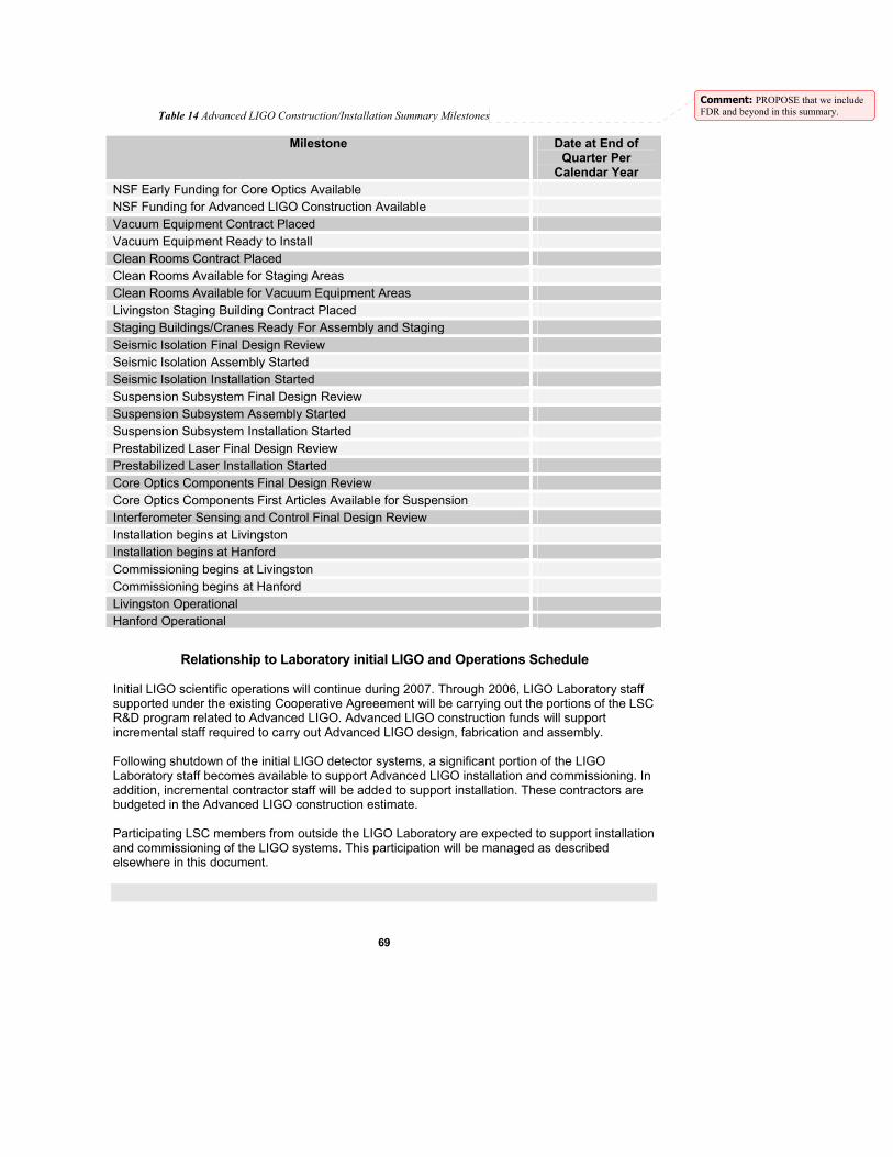
69
Table 14 Advanced LIGO Construction/Installation Summary Milestones
Milestone Date at End of Quarter Per
Calendar Year NSF Early Funding for Core Optics Available NSF Funding for Advanced LIGO Construction Available Vacuum Equipment Contract Placed Vacuum Equipment Ready to Install Clean Rooms Contract Placed Clean Rooms Available for Staging Areas Clean Rooms Available for Vacuum Equipment Areas Livingston Staging Building Contract Placed Staging Buildings/Cranes Ready For Assembly and Staging Seismic Isolation Final Design Review Seismic Isolation Assembly Started Seismic Isolation Installation Started Suspension Subsystem Final Design Review Suspension Subsystem Assembly Started Suspension Subsystem Installation Started Prestabilized Laser Final Design Review Prestabilized Laser Installation Started Core Optics Components Final Design Review Core Optics Components First Articles Available for Suspension Interferometer Sensing and Control Final Design Review Installation begins at Livingston Installation begins at Hanford Commissioning begins at Livingston Commissioning begins at Hanford Livingston Operational Hanford Operational
Relationship to Laboratory initial LIGO and Operations Schedule Initial LIGO scientific operations will continue during 2007. Through 2006, LIGO Laboratory staff supported under the existing Cooperative Agreeement will be carrying out the portions of the LSC R&D program related to Advanced LIGO. Advanced LIGO construction funds will support incremental staff required to carry out Advanced LIGO design, fabrication and assembly. Following shutdown of the initial LIGO detector systems, a significant portion of the LIGO Laboratory staff becomes available to support Advanced LIGO installation and commissioning. In addition, incremental contractor staff will be added to support installation. These contractors are budgeted in the Advanced LIGO construction estimate. Participating LSC members from outside the LIGO Laboratory are expected to support installation and commissioning of the LIGO systems. This participation will be managed as described elsewhere in this document.
Comment: PROPOSE that we include FDR and beyond in this summary.
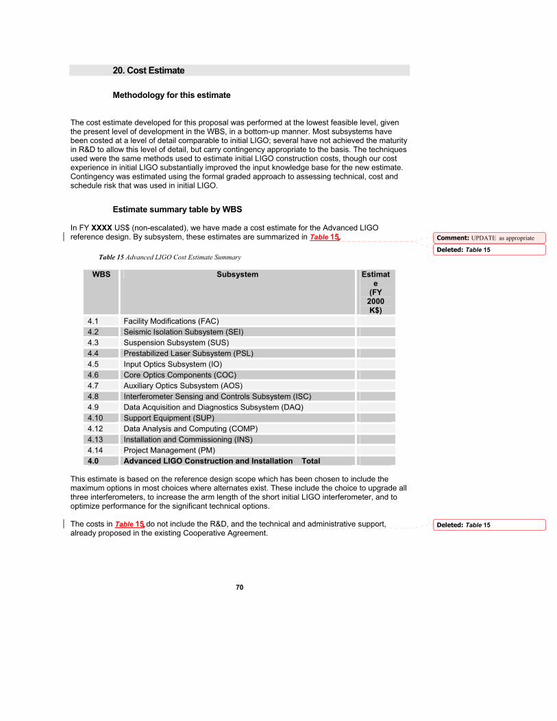
70
20. Cost Estimate
Methodology for this estimate The cost estimate developed for this proposal was performed at the lowest feasible level, given the present level of development in the WBS, in a bottom-up manner. Most subsystems have been costed at a level of detail comparable to initial LIGO; several have not achieved the maturity in R&D to allow this level of detail, but carry contingency appropriate to the basis. The techniques used were the same methods used to estimate initial LIGO construction costs, though our cost experience in initial LIGO substantially improved the input knowledge base for the new estimate. Contingency was estimated using the formal graded approach to assessing technical, cost and schedule risk that was used in initial LIGO.
Estimate summary table by WBS In FY XXXX US$ (non-escalated), we have made a cost estimate for the Advanced LIGO reference design. By subsystem, these estimates are summarized in Table 15.
Table 15 Advanced LIGO Cost Estimate Summary
WBS Subsystem Estimate
(FY 2000 K$)
4.1 Facility Modifications (FAC) 4.2 Seismic Isolation Subsystem (SEI) 4.3 Suspension Subsystem (SUS) 4.4 Prestabilized Laser Subsystem (PSL) 4.5 Input Optics Subsystem (IO) 4.6 Core Optics Components (COC) 4.7 Auxiliary Optics Subsystem (AOS) 4.8 Interferometer Sensing and Controls Subsystem (ISC) 4.9 Data Acquisition and Diagnostics Subsystem (DAQ) 4.10 Support Equipment (SUP) 4.12 Data Analysis and Computing (COMP) 4.13 Installation and Commissioning (INS) 4.14 Project Management (PM) 4.0 Advanced LIGO Construction and Installation Total
This estimate is based on the reference design scope which has been chosen to include the maximum options in most choices where alternates exist. These include the choice to upgrade all three interferometers, to increase the arm length of the short initial LIGO interferometer, and to optimize performance for the significant technical options. The costs in Table 15 do not include the R&D, and the technical and administrative support, already proposed in the existing Cooperative Agreement.
Comment: UPDATE as appropriate
Deleted: Table 15
Deleted: Table 15
71
The GEO Project has proposed to provide a capital investment in this construction project. The UK proposal is for approximately $12 million8,31. They propose to apply these resources to providing the suspension subsystem, including suspension assemblies, their controls, and installation and commissioning. This is a particularly appropriate contribution to Advanced LIGO as the suspension subsystem is based upon the GEO Project implementation for the GEO 600 interferometer The German proposal is for the design and fabrication of the pre-stabilized laser subsystem, with the amount in discussion. With the GEO capital contribution, the requested US Advanced LIGO costs are $ XXXXX K in FY 2000 $. Escalating this sum to the approximate mid-point of Advanced LIGO construction (2004), using the average inflation rate quoted by the US Department of Labor for the last 6 years (2.4%), yields a total request to the NSF of $ XXXXX K. Should the GEO capital contribution not materialize in full, the Advanced LIGO reference design will be de-scoped to control the request to assure that the final requested funding is less than or equal to the estimate above.
Cost Drivers Significant cost drivers in the Advanced LIGO estimate include: • Upgrading of three interferometers • Rapid and closely sequential assembly and installation • Use of isolation systems with multiple actively controlled degrees of freedom • Use of multiple pendulum suspensions with additional stages and active controls • Stringent isolation requirements for smaller optics • Higher power lasers requiring expensive laser diodes and thermal control measures • Large core optics of ether sapphire or fused silica (comparable cost) • High number of control loops • High channel count for diagnostic channels • Increased detector sensitivity and bandwidth • Greater data storage needs • Greater communications bandwidth needs
Risk Areas and Contingency Contingency has been estimated for each subsystem based upon top-level estimates by subsystem. Of the total FY 2000 $ estimate above, contingency funds have been estimated to be $ XXXXX K. The estimate is substantially based upon well known unit costs, great conservatism has been used in carrying out the estimate, and most subsystems have substantial potential for de-scoping. The combination of established unit costs and labor rates, and the large scope contingency support this estimate. If decisions are made to reduce scope, funds will be added to the contingency pool to offset the scope contingency.
Funding Profile A working funding profile has been calculated which enables the planned schedule. We note that long-lead-time procurements such as the purchase of vacuum equipment components, and purchase of large optics substrates, will define early funding needs.
31 Private communication, K. Danzmann and J. Hough, 8 January 2003.
Comment: update: UK Glasgow at 12M, Germany at something else
Comment: update
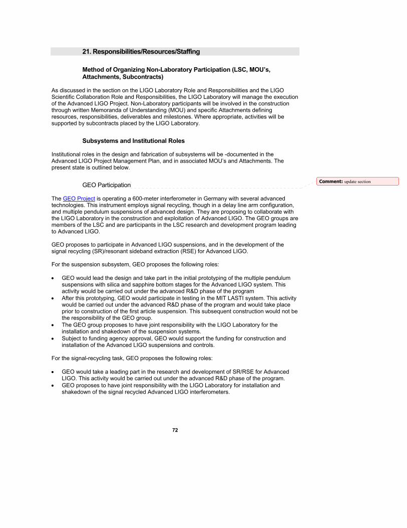
72
21. Responsibilities/Resources/Staffing
Method of Organizing Non-Laboratory Participation (LSC, MOU’s, Attachments, Subcontracts)
As discussed in the section on the LIGO Laboratory Role and Responsibilities and the LIGO Scientific Collaboration Role and Responsibilities, the LIGO Laboratory will manage the execution of the Advanced LIGO Project. Non-Laboratory participants will be involved in the construction through written Memoranda of Understanding (MOU) and specific Attachments defining resources, responsibilities, deliverables and milestones. Where appropriate, activities will be supported by subcontracts placed by the LIGO Laboratory.
Subsystems and Institutional Roles Institutional roles in the design and fabrication of subsystems will be -documented in the Advanced LIGO Project Management Plan, and in associated MOU’s and Attachments. The present state is outlined below.
GEO Participation The GEO Project is operating a 600-meter interferometer in Germany with several advanced technologies. This instrument employs signal recycling, though in a delay line arm configuration, and multiple pendulum suspensions of advanced design. They are proposing to collaborate with the LIGO Laboratory in the construction and exploitation of Advanced LIGO. The GEO groups are members of the LSC and are participants in the LSC research and development program leading to Advanced LIGO. GEO proposes to participate in Advanced LIGO suspensions, and in the development of the signal recycling (SR)/resonant sideband extraction (RSE) for Advanced LIGO. For the suspension subsystem, GEO proposes the following roles: • GEO would lead the design and take part in the initial prototyping of the multiple pendulum
suspensions with silica and sapphire bottom stages for the Advanced LIGO system. This activity would be carried out under the advanced R&D phase of the program
• After this prototyping, GEO would participate in testing in the MIT LASTI system. This activity would be carried out under the advanced R&D phase of the program and would take place prior to construction of the first article suspension. This subsequent construction would not be the responsibility of the GEO group.
• The GEO group proposes to have joint responsibility with the LIGO Laboratory for the installation and shakedown of the suspension systems.
• Subject to funding agency approval, GEO would support the funding for construction and installation of the Advanced LIGO suspensions and controls.
For the signal-recycling task, GEO proposes the following roles: • GEO would take a leading part in the research and development of SR/RSE for Advanced
LIGO. This activity would be carried out under the advanced R&D phase of the program. • GEO proposes to have joint responsibility with the LIGO Laboratory for installation and
shakedown of the signal recycled Advanced LIGO interferometers.
Comment: update section
73
GEO is making a proposal for a capital contribution to Advanced LIGO. They are at the final stages of approval for a proposal to the UK Particle Physics and Astronomy Research Council for a large part of the suspension subsystem and for part of the core optics. A companion proposal for provision of the laser system is about to be submitted to the relevant German funding authority. With approval of these initiatives by the respective funding agencies, and agreements contained in MOUs and specific Attachments, the GEO groups will become partners in the leadership and execution of the Advanced LIGO project.
Comment: ADD SECTION on ACIGA