advanced maritime emissions control system...
TRANSCRIPT

Advanced Maritime EmissionsAdvanced Maritime EmissionsControl System (AMECSControl System (AMECS®®))
Advanced Cleanup Technologies, IncorporatedAdvanced Cleanup Technologies, Incorporated
Hazardous Waste Management & EmissionsHazardous Waste Management & EmissionsControl SpecialistsControl Specialists
Environmental Systems Development DivisionEnvironmental Systems Development Division
Creating a better Environment through ScienceCreating a better Environment through Science

The ProblemThe Problem

Depiction of Various Ship Depiction of Various Ship Stack ConfigurationsStack Configurations
Can Accommodate Various Can Accommodate Various Stack ShapesStack Shapes
The PROBLEM (continued)The PROBLEM (continued)
The Exhaust Capture System must The Exhaust Capture System must accommodate various stack accommodate various stack
geometriesgeometries

The PROBLEM (continued)The PROBLEM (continued)
The system must be able to treat various The system must be able to treat various fuel types, handle various exhaust flows fuel types, handle various exhaust flows
and exhaust temperaturesand exhaust temperatures
The SolutionThe Solution

Emissions Control TechnologyEmissions Control Technology
ACTIACTI’’ss Emissions Control Technology consists of Emissions Control Technology consists of two types of systems:two types of systems:
•• Advanced Locomotive Emissions Control Advanced Locomotive Emissions Control System (ALECS) designed to capture and treatSystem (ALECS) designed to capture and treatthe exhaust emissions from railroad locomotivesthe exhaust emissions from railroad locomotives
•• Advanced Maritime Emissions Control Advanced Maritime Emissions Control System (AMECS) designed to capture and treatSystem (AMECS) designed to capture and treatthe exhaust emissions from oceanthe exhaust emissions from ocean--going vesselsgoing vessels
–– BargeBarge--Based SystemBased System
–– ShoreShore--Based SystemBased System
–– MultiMulti--Capture and Treatment System Capture and Treatment System

Emissions Treatment SubsystemEmissions Treatment SubsystemPicture of the Actual SystemDemonstrated and Tested in
Roseville, California

Successful Demonstration ProgramSuccessful Demonstration Program
•• The objective of the tests at Union Pacific The objective of the tests at Union Pacific RailroadRailroad’’s J. R. Davis rails J. R. Davis rail--yard in Roseville, yard in Roseville, California was to demonstrate ALECS California was to demonstrate ALECS capability to:capability to:
-- Remotely attach to a railroad locomotive Remotely attach to a railroad locomotive around the exhaust openingaround the exhaust opening
-- Capture the exhaust gas and direct it via Capture the exhaust gas and direct it via the overhead manifold system into the the overhead manifold system into the Emissions Treatment SubsystemEmissions Treatment Subsystem

-- Maintain attachment and exhaust capture Maintain attachment and exhaust capture while the railroad locomotive is underway while the railroad locomotive is underway within designated area within the rail within designated area within the rail yardsyards
•• The test of ALECS was a success, meeting The test of ALECS was a success, meeting all the goals described above and moreall the goals described above and more
•• The same treatment system is used on The same treatment system is used on AMECSAMECS
Successful Demonstration Program Successful Demonstration Program (continued)(continued)

Successful Demonstration Program Successful Demonstration Program (continued)(continued)

ShoreShore--Based Based AMECS AMECS
ConfigurationConfiguration

BargeBarge--Based AMECS Based AMECS ConfigurationConfiguration

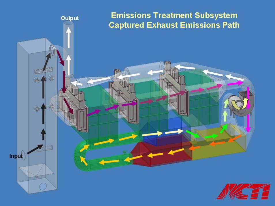
Emissions Treatment SubsystemEmissions Treatment Subsystem
Preconditioning Preconditioning Chamber (PCC)Chamber (PCC)
Outlet GasOutlet Gas
Cloud Generation Cloud Generation Chambers (CGC)Chambers (CGC)
Inlet GasInlet Gas
System ID FanSystem ID Fan
HeatHeat--ExchangerExchanger
Heater (Burner)Heater (Burner)
Selective Catalytic Reduction (SCR)Selective Catalytic Reduction (SCR)
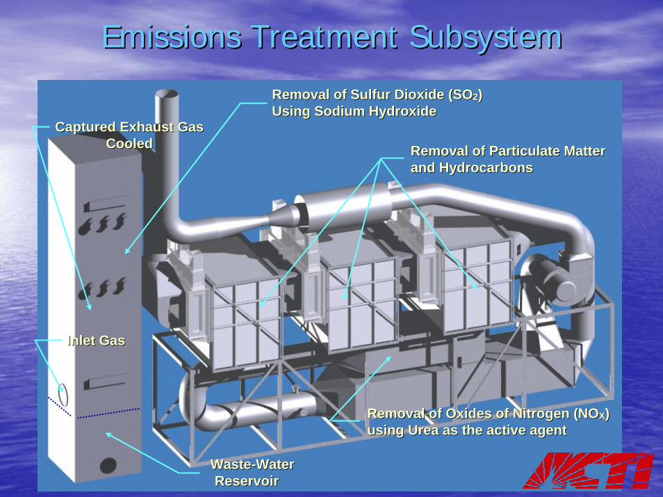
Emissions Treatment SubsystemEmissions Treatment Subsystem
WasteWaste--Water Water ReservoirReservoir
Captured Exhaust Gas Captured Exhaust Gas CooledCooled
Removal of Sulfur Dioxide (SORemoval of Sulfur Dioxide (SO22) ) Using Sodium HydroxideUsing Sodium Hydroxide
Removal of Particulate Matter Removal of Particulate Matter and Hydrocarbonsand Hydrocarbons
Inlet GasInlet Gas
Removal of Oxides of Nitrogen (NORemoval of Oxides of Nitrogen (NOXX) ) using Urea as the active agent using Urea as the active agent

Emissions Capture SubsystemEmissions Capture Subsystem
Maximum Envelope 125 Feet
Maximum Envelope 125 Feet
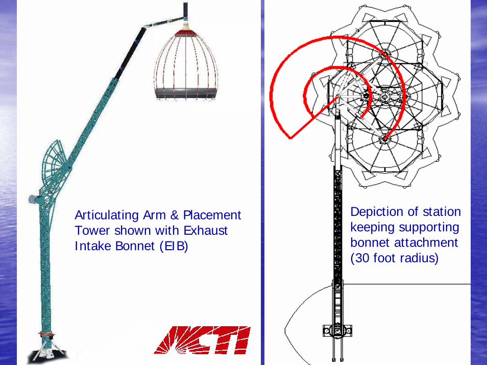
Depiction of station keeping supporting bonnet attachment (30 foot radius)
Articulating Arm & Placement Tower shown with Exhaust Intake Bonnet (EIB)

Articulating Arm & Placement TowerArticulating Arm & Placement Tower
Articulating Arm Articulating Arm (for EIB placement)(for EIB placement)
Counter BalanceCounter Balance
Expandable Expandable BoomBoom
Cable Drive AssemblyCable Drive Assembly
Peacock Peacock AssemblyAssembly
Placement TowerPlacement Tower

Emissions Intake Bonnet (EIB)Emissions Intake Bonnet (EIB)
Side Views of EIB, Side Views of EIB, shown in closed shown in closed position with Shroud position with Shroud withdrawnwithdrawn
Carbon Fiber Carbon Fiber RibsRibs
High temperature High temperature ShroudShroud

EIB Station KeepingEIB Station Keeping
Wire SensorsWire Sensors
Soft TriSoft Tri--Pod Stack InterfacePod Stack Interface
•• Three fixed stack points connected Three fixed stack points connected to floating arm measure stack to floating arm measure stack position (EIB shown in closed position (EIB shown in closed position)position)
•• Wire sensors allow for rapid and Wire sensors allow for rapid and accurate arm adjustmentaccurate arm adjustment
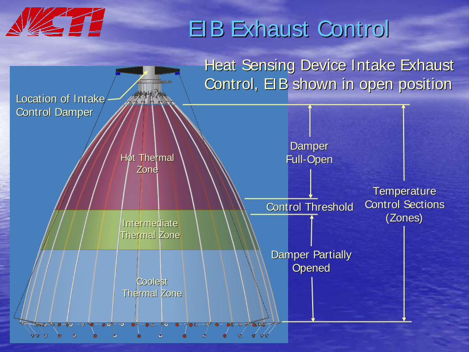
EIB Exhaust ControlEIB Exhaust ControlHeat Sensing Device Intake Exhaust Heat Sensing Device Intake Exhaust Control, EIB shown in open positionControl, EIB shown in open position
Location of Intake Location of Intake Control DamperControl Damper
Temperature Temperature Control Sections Control Sections
(Zones)(Zones)
Damper Partially Damper Partially OpenedOpened
Damper Damper FullFull--OpenOpenHot Thermal Hot Thermal
ZoneZone
Intermediate Intermediate Thermal ZoneThermal Zone
Coolest Coolest Thermal ZoneThermal Zone
Control ThresholdControl Threshold

EIB Wire Position SensorsEIB Wire Position Sensors(Station Keeping)(Station Keeping)
Soft TriSoft Tri--Pod Standoff Pod Standoff Stack InterfaceStack Interface
Wire Sensors (Set of Three)Wire Sensors (Set of Three)
•• Three fixed stack points Three fixed stack points connected to floating arm connected to floating arm measuring stack positionmeasuring stack position
•• Wire sensors allow for rapid Wire sensors allow for rapid and accurate arm adjustmentand accurate arm adjustment
•• Wire Sensor designed and Wire Sensor designed and manufactured by Micromanufactured by Micro--EpsilonEpsilon

EIB Station Keeping Sensor SystemEIB Station Keeping Sensor System
Positioning SensorsPositioning Sensors
Wire SensorsWire Sensors
Positioning Standoffs Positioning Standoffs (three)(three)
•• Wire sensors accurate to Wire sensors accurate to within within ±± .1 inches.1 inches
•• Determines arm position Determines arm position relative to stack within one relative to stack within one inchinch
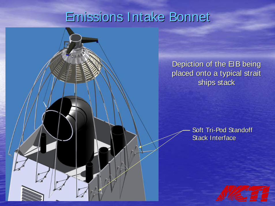
Emissions Intake BonnetEmissions Intake Bonnet
Depiction of the EIB being Depiction of the EIB being placed onto a typical strait placed onto a typical strait
ships stackships stack
Soft TriSoft Tri--Pod Standoff Pod Standoff Stack InterfaceStack Interface

Emissions Intake BonnetEmissions Intake Bonnet
Depiction of the EIB being Depiction of the EIB being placed onto lip style stackplaced onto lip style stack
Station Keeping Wire SensorsStation Keeping Wire Sensors

Minimal Impact, if any, on Minimal Impact, if any, on Port OperationsPort Operations
Ease of access to stackEase of access to stack
Unobtrusive Barge Unobtrusive Barge LocationLocation

Depiction of Attachment While Depiction of Attachment While AnchoredAnchored
Unobtrusive barge Unobtrusive barge attachment while OGV attachment while OGV
is anchoredis anchored

Typical Attachment Shown for Single Stack Vessel
Articulating Arm
Vertical Compensator
Emissions Intake Bonnet (EIB) shown unfurled

Typical Attachment Shown for Dual-Stack Vessel
Vertical Compensator
Pair of Emissions Intake Bonnet’s (EIBs) shown furled

SUMMARYSUMMARY
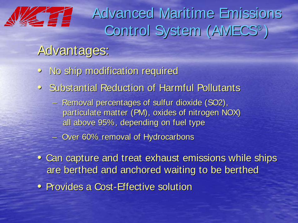
Advanced Maritime Emissions Advanced Maritime Emissions Control System (AMECSControl System (AMECS®®))
Advantages:Advantages:•• No ship modification requiredNo ship modification required
•• Substantial Reduction of Harmful PollutantsSubstantial Reduction of Harmful Pollutants–– Removal percentages of sulfur dioxide (SO2), Removal percentages of sulfur dioxide (SO2),
particulate matter (PM), oxides of nitrogen NOX) particulate matter (PM), oxides of nitrogen NOX) all above 95%, depending on fuel typeall above 95%, depending on fuel type
–– Over 60% removal of HydrocarbonsOver 60% removal of Hydrocarbons
•• Can capture and treat exhaust emissions while shipsCan capture and treat exhaust emissions while shipsare berthed and anchored waiting to be berthed are berthed and anchored waiting to be berthed
•• Provides a CostProvides a Cost--Effective solutionEffective solution

Questions & AnswersQuestions & AnswersAdvanced Cleanup Technologies, Advanced Cleanup Technologies,
IncorporationIncorporationHazardous Waste Management SpecialistsHazardous Waste Management Specialists
18414 South Santa Fe Avenue18414 South Santa Fe AvenueRancho Dominguez, California 90221Rancho Dominguez, California 90221--56125612
310 763310 763--14231423

Supporting DataSupporting Data
The following slides contain The following slides contain additional information regardingadditional information regarding
ACTI’s Advanced Maritime Advanced Maritime Emissions Control System Emissions Control System
(AMECS), and will only be used (AMECS), and will only be used as required to respond to as required to respond to
questionsquestions

EIB Light Wind ApplicationsEIB Light Wind Applications
Bellows Bonnet Designed for Light Bellows Bonnet Designed for Light Wind ApplicationsWind Applications
SideSide--ViewView
TopTop--ViewView

EIB Stack Interface SystemEIB Stack Interface System
Swivels (four)Swivels (four)
Soft Interface Soft Interface PadsPads
TriTri--Pod Standoff Stack Pod Standoff Stack Interface SystemInterface System

EIB Securing & Release SystemEIB Securing & Release System
Securing SystemSecuring System
Cinching Cables (sown in Cinching Cables (sown in blue) after attachmentblue) after attachment
Cinching Cables (shown Cinching Cables (shown in red) prior to in red) prior to attachmentattachment

SCR Reactor, Injection System & BurnerSCR Reactor, Injection System & Burner
Directed into front of system
Catalyst
Cleaned Gas
Exhaust Gas
Heater Control
Urea
NOx
NOxNOx
NOx
NH3
NH3
NH3
NH3
H20H20
H20
H20
N2
N2
N2
N2
H2O
Diesel Fuel

Thermal Management SystemThermal Management System
Hot Exhaust
Scrubbed Gas
CleanExhaust Stream
Urea
Heat Exchanger
SCR Reactor
Diesel Generator
Cloud Chamber Scrubber
Hot Exhaust
Captured Hot Engine
Exhaust
Hot Exhaust

SCR Reactor SCR Reactor –– Argillon CatalystArgillon Catalyst
•• Titanium Titanium –– Vanadium Oxide TiVanadium Oxide Ti--VV22OO55 BasedBased
•• Ceramic SubstrateCeramic Substrate
•• HomogeneousHomogeneous
•• HoneycombHoneycomb

SCR Catalyst PerformanceSCR Catalyst Performance
Designed input temperature range
NOx Removal Efficiency vs. Operating Temperature(Design Temperature = 600o to 680o F)
50.0
60.0
70.0
80.0
90.0
100.0
400 450 500 550 600 650 700 750 800
Operating Temperature (F)
NO
x R
emov
al E
ffici
ency
(%)
Designed input temperature range

AMECS ImprovementsAMECS Improvements
Under Lessons Leaned:Under Lessons Leaned:
The following two improvements are under consideration as a resuThe following two improvements are under consideration as a result of the lt of the Demonstration and Testing Program in Roseville, CaliforniaDemonstration and Testing Program in Roseville, California
•• Create one common housing partition between the Selective CataCreate one common housing partition between the Selective Catalyst lyst Reduction (SCR) Reactor and the Thermal Management System (showReduction (SCR) Reactor and the Thermal Management System (shown in n in the next slide). This would increase thermal efficiency and redthe next slide). This would increase thermal efficiency and reduce the system uce the system cost.cost.
•• Continuous Emissions Monitoring System (CEMS); the system deplContinuous Emissions Monitoring System (CEMS); the system deployed oyed seems to require a greater amount of technical skill then we belseems to require a greater amount of technical skill then we believe is ieve is necessary. In addition, the system cost seems to be high. We wnecessary. In addition, the system cost seems to be high. We will evaluate ill evaluate other systems. other systems.
•• We developed a much better understanding of rail yard operationWe developed a much better understanding of rail yard operations and the s and the type of exhaust capture system that would most likely work withotype of exhaust capture system that would most likely work without ut interfering with railroad operations. interfering with railroad operations.

AMECS Improvements AMECS Improvements (continued)(continued)
Thermal Management System
Old Design
SCR Reactor & Burner
Assembly Heat-ExchangerNew Design