advanced materials manufacturing & characterization ... · purpose metal forming simulator...
TRANSCRIPT
________________
Corresponing author: Rakshith T E-mail address: [email protected]
Doi: http://dx.doi.org/10.11127/ijammc.2016.04.15 Copyright@GRIET Publications. All rights reserved.
Advanced Materials Manufacturing & Characterization Vol 6 Issue 1 (2016)
Advanced Materials Manufacturing & Characterization
journal home page: www.ijammc-griet.com
Optimization Of Parameters For Elbow Component Using Manufacturing Simulation
Rakshith T.1 M. S. Srinath2 Y. Arunkumar3 Hemanth S Thulasi4
PG student, Dept. of IAR, Malnad College of Engineering, Hassan, India Professor, Dept. of Mechanical Engineering, Malnad College of Engineering, Hassan, India
Professor, Dept. of I&P, Malnad College of Engineering, Hassan, India Research Scholar, Dept. of Mechanical Engineering, Malnad College of Engineering, Hassan
A B S T R A C T
Pre forming state of a segment assumes a vital part in mass shaping
procedure. Pre forming operation in manufacturing of billet and
planning of die assumes an extensive part in forging procedure. The
parameters that are considered in designing and analysis of forging
dies are under fill, cracks flash allowance and uniform stress and strain.
In the present examination it was found that the impact of these
parameters would influence on the nature of forgings. To take
advantages of models and materials method, and to bring down the
expenses, computer simulation has been utilized, however, it copies the
real process and gives a watched worth for producing load, flash
allowance, unfilled zones and die cavity filling. Through computer
simulation it is conceivable to get powerful stress and strain
distribution in axis symmetric die forging. In the present work
compelling plan of lower and upper die on for a automotive module,
elbow and its proportionate billet outline has been made by utilizing
UNIGRAPHICS NX 8 CAD tool. These models are imported to general
purpose metal forming simulator software AFDEX-2014. Simulation of
closed die forging has been carried out by conveying all the vital
parameters like temperature, materials, lubricants, density and so on.
Several iterations have been done by changing the dimensions of initial
billet to reduce unfilled area, flash, even distribution of stress and
strain and also optimization of billet size has been achieved.
Keywords: Closed die forging; Elbow; AFDEX; Flash; Uniform stress distribution
1. INTRODUCTION
1.1 Forging is the working of metal into a valuable shape by
pounding or squeezing. It is considered as one of the most
established metal working arts [1]. Hot and warm producing
innovation has picked up parcel of potential as of late in
automobile and aviation industries [2]. In present day
scenario on account of immense necessities in the produced
part and centered towards the benefit, it has turn out to be
essential to advance the quality, expenses and lead time.
Normally forging procedure includes numerous pre-shaping
procedures which are then trailed by completing procedure.
1.2 Simulation has turn out to be essential instrument for the
improvement of new or enhancing procedures. Simulation is
being utilized to simulate number of shaping procedures
underway of segments like interfacing bars, razor sharp edge
and different parts utilizing different simulation software [3].
The simulation procedure will cut down the time and expense
of advancement of new products [4].
1.3 In producing procedure, obliged last shape is exceptionally
hard to acquire when the introductory conditions are not
changed in light of the fact that the beginning state of the
work piece impacts on the last shape. Inquires about were
done to diminish unfilled zone and flash for even dispersion
of stress and strain utilizing the ESL system.
1.4 Producing segments assumes an essential part in automotive
and aerospace industry. Upgrading the parameters is
imperative to enhance the nature of forged segments. A few
079
works has been done in this respects. A portion of the
overwhelming obligation segments which are utilized as a
part of car industry and other mechanical applications are
streamlined for expanded proficiency to convey high load
limit and high weakness resistance by refining the grain
structure [6].One such parameter is preformed shape, which
is improved by utilizing FE Simulation [5].Computer supported
simulation is utilized as a part of examining the material
stream in a few manufacturing operations [3]. Numerical
simulation methods are utilized for checking of voids
advancement while forging operations [6]. Shape
optimization of work piece is done by utilizing the
comparable static burden for manufacturing process [3].
Impact of the mold plan on the cementing of substantial
forging is done utilizing numerical simulation [4].
1.5 There are diverse programming or numerical systems
accessible for optimizing the procedures including DEFORM
3D, AFDEX, FORGE, STATISTICA, ANSYS, FEM, Monte Carlo
technique and numerous other methods[5],[6].
1.6 In this paper the parameters like billet shape, under fill,
strain, stress, die contact and hydrostatic pressure is
considered to simulate and analyze the closed die process.
Pre-structure shape and improvement of the outline assumes
a huge part in mass framing procedure for choosing the
measure of material devoured and energy alongside the
material stream analysis [5]. The main focus of the present
work is to diminish flash utilizing the assembling simulation
for the material AISI 1015 carbon steel (800 C - 1200 C) of the
elbow plan. 2. DESIGN METHODOLOGY
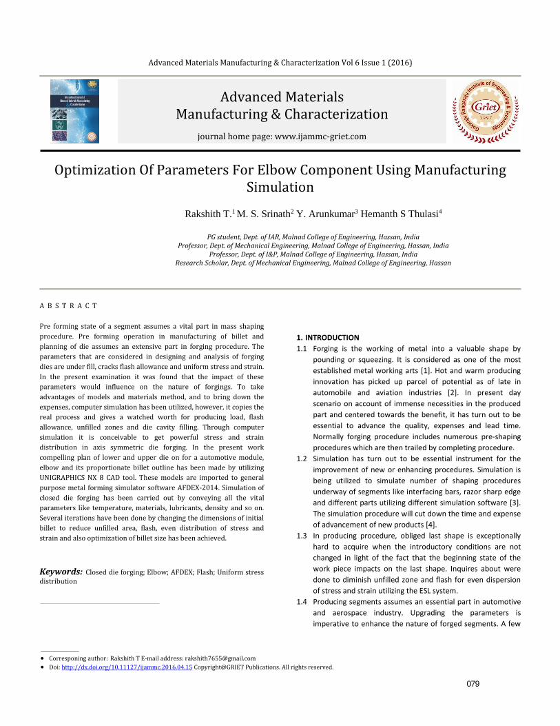
2.1 SIMULATION PROCEDURE In this investigation, the detailed steps involved to carry out
simulations highlighted in Fig.1. Preparatory stage part geometry
is considered for the investigation and after that CAD model is
created utilizing UG NX tool. Taking into account the model
suitable dies on are outlined in the same bundle. Contingent upon
the model chose and its capacity, material is chosen in such a
route to the point that the part can work. Regarding the material
organization and the property for the given item, dies material is
chosen.
Fig.1. Step by step procedure
involved in simulation of forging process.
Once the CAD model is prepared, the next step is to simulate the
process and AFDEX tool is used for simulation.
If there are any errors or deformities found, relating changes are
made in die configuration and/or in billet shape and size. Changes
has been done without much of a stretch be actualized in outline
stages to enhance the nature of finished product. This simulation
procedure is preceded till the minimum deformities are
accomplished.
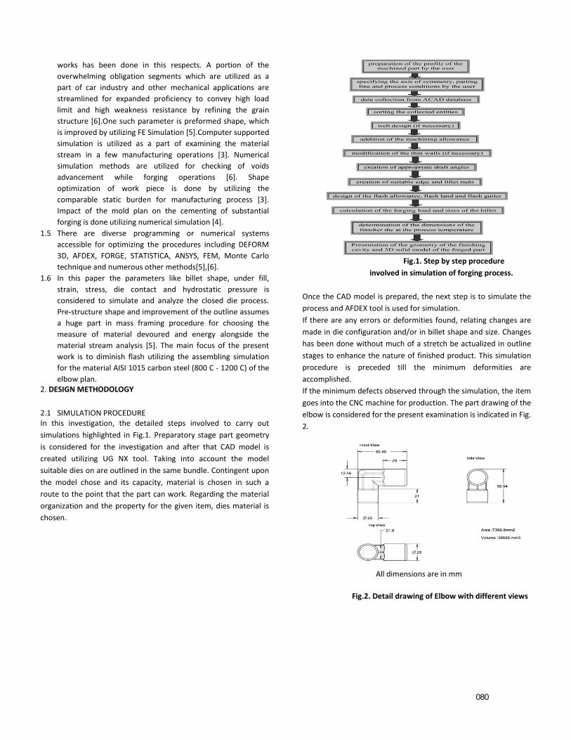
If the minimum defects observed through the simulation, the item
goes into the CNC machine for production. The part drawing of the
elbow is considered for the present examination is indicated in Fig.
2.
All dimensions are in mm
Fig.2. Detail drawing of Elbow with different views
080
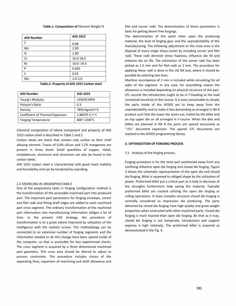
Table.1. Composition of Element Weight %
AISI Number AISI 1015
C 0.08
Mn 2.00
Si 1.00
Cr 16.0-18.0
Ni 10.0- 14.0
P 0.045
S 0.03
Mo 2.0-3.0
Table.2. Property of AISI 1015 Carbon steel
AISI Number AISI 1015
Young's Modulus 159250 MPA
Poisson's Ratio 0.3
Density 7850 Kgm/m^3
Coefficient of Thermal Expansion 1.8007E-5 /o C
Forging Temperature 800°-1200°C
Chemical composition of elbow component and property of AISI
1015 carbon steel is described in Table 1 and 2.
Carbon steels are steels that contain only carbon as their chief
alloying element. Traces of 0.4% silicon and 1.2% manganese are
present in these steels. Small quantities of copper, nickel,
molybdenum, aluminum and chromium can also be found in the
carbon steels.
AISI 1015 carbon steel is characterized with good mach inability
and formability and can be hardened by cyaniding.
2.2 MODELING IN UNIGRAPHICS NX8.0 One of the preparatory tasks in forging configuration method is
the transformation of the accessible machined part into produced
part. The important part parameters for forging envelope, corner
and filet radii and fitting draft edges are added to each machined
part cross segment. The ordinary transformation of the machined
part information into manufacturing information obliges a lot of
time. In the present CAD strategy, the procedure of
transformation is to a great extent improved by utilization of the
intelligence with the realistic screen. This methodology can be
connected to an extensive number of forging segments and the
information needed to do this change have been spared inside of
the computer, so that is accessible for less experienced clients.
The cross segment is acquired by a three dimensional machined
part geometry. This cross area should be altered to adjust to
process constraints. This procedure includes choice of the
separating lines, expansion of machining and draft allowance and
filet and corner radii. The determination of these parameters is
basic for getting desert free forgings.
The determination of this point relies upon the producing
material, the kind of forging gear and the unpredictability of the
manufacturing. The following adjustment to the cross area is the
disposal of every single sharp comer by including corner and filet
radii. These radii diminish stress fixations, influence die fill and
enhance die on life. The estimation of the comer radii has been
picked as 1.5 mm and for filet radii as 2 mm. The procedure for
applying these radii is done in the UG NX tool, where it should be
possible by selecting two lines.
Machine recompense of 2 mm is included while simulating for all
sides of the segment. In any case, for assembling reason the
allowance is included depending on physical structure of the part.
STL records the introduction ought to be in Y-heading as the load
connected would be in this course. It is even conceivable to situate
the parts inside of the AFDEX yet to keep away from the
unpredictability and to make it less demanding as arranged in NX 8
product such that the lower die starts out, trailed by the billet and
on top upper die on all arranged in Y-course. When the dies and
billets are planned in NX 8 the parts are spared exclusively as
".STL" document expansion. The spared .STL documents are
stacked to the AFDEX programming library.
3. OPTIMIZATION OF FORGING PROCESS
3.1 Analysis of the forging process
Forging procedure is for the most part partitioned away from any
confining influence open die forging and closed die forging. Figure
3 shows the schematic representation of the open die and closed
die forging. Billet is squeezed to obliged shape by the utilization of
power. Preformed billet put a critical part as it help in decrease of
the strengths furthermore help saving the material. Typically
preformed billet are created utilizing the open die forging or
rolling operations. In least complex structure closed die forging is
normally considered as impression die producing. The parts
delivered by closed die forging have high quality and great weight
proportion when contrasted with other machined parts. Closed die
forging is more favored than open die forging. Be that as it may,
closed die forging is not temperate, introductory and support
expense is high relatively. The preformed billet is acquired as
demonstrated in the Fig. 4.
081
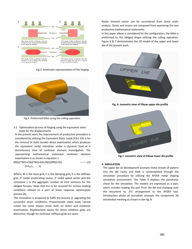
Fig.3. Schematic representation of the forging
Fig.4. Preformed billet using the rolling operation
3.2 Optimization process of forging using the equivalent static loads for the displacements
In the present work the improvement of production procedure is
considered by utilizing the Equivalent Static Loads (ESL). ESL is for
the removal of static burden direct examination which produces
the equivalent nodal relocation under a dynamic load at a
discretionary time of nonlinear element investigation. The
representing mathematical statement nonlinear element
examination is as shown in equation 1.
M(b)Z"N(t)+C(b)Z'N(t)+K(b,ZN(t))ZN(t)=f(t) --------(1)
(t=t0,t1,. . . . tl)
Where, M is the mass grid, C is the damping grid, K is the stiffness
grid, Z" nodal accelerating vector, Z' nodal speed vector and the
consistent L is the aggregate number of time ventures for the
obliged focuses. Steps that are to be received for various loading
conditions utilized as a part of linear response optimization
process [6].
This innovation is proposed to fulfill the process in upgrading the
successful strain conditions. Proportionate static loads cannot
create the same impact strain both on direct and nonlinear
examination. Displacement vector for direct solidness grids are
distinctive, though for nonlinear stiffness grids are same.
Nodal removal vector can be ascertained from linear static
analysis. Stress and strains are computed from examining the two
productive mathematical statements.
In this paper elbow is considered for the configuration, the billet is
preformed to the obliged shape utilizing the rolling operation.
Figure 6 & 7 demonstrates the 3D model of the upper and lower
die of the present work.
Fig. 6. Isometric view of Elbow upper die profile
Fig.7. Isometric view of Elbow lower die profile
4. SIMULATION The upper die on development prompts metal stream of pattern
into the die cavity and flash is contemplated through the
simulation procedure by utilizing the AFDEX metal shaping
simulation environment. The Table 3 displays the parameter
chose for the simulation. The models are expressed as a part,
which includes loading the part from the NX and changing over
the document to .STL arrangement to the AFDEX tool.
Introductory phase of recreation prompts the component 3D
tetrahedral meshing as shown in the Fig. 8.
082
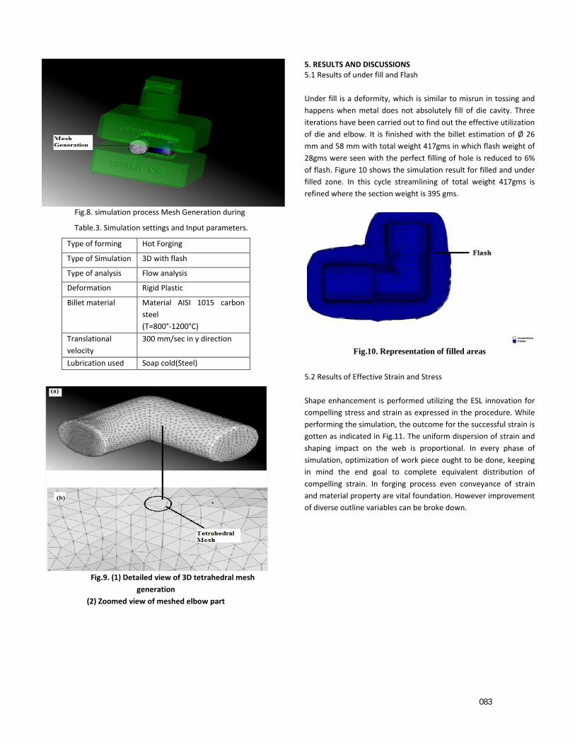
Fig.8. simulation process Mesh Generation during
Table.3. Simulation settings and Input parameters.
Type of forming Hot Forging
Type of Simulation 3D with flash
Type of analysis Flow analysis
Deformation Rigid Plastic
Billet material Material AISI 1015 carbon
steel
(T=800°-1200°C)
Translational
velocity
300 mm/sec in y direction
Lubrication used Soap cold(Steel)
Fig.9. (1) Detailed view of 3D tetrahedral mesh
generation
(2) Zoomed view of meshed elbow part
5. RESULTS AND DISCUSSIONS 5.1 Results of under fill and Flash
Under fill is a deformity, which is similar to misrun in tossing and
happens when metal does not absolutely fill of die cavity. Three
iterations have been carried out to find out the effective utilization
of die and elbow. It is finished with the billet estimation of Ø 26
mm and 58 mm with total weight 417gms in which flash weight of
28gms were seen with the perfect filling of hole is reduced to 6%
of flash. Figure 10 shows the simulation result for filled and under
filled zone. In this cycle streamlining of total weight 417gms is
refined where the section weight is 395 gms.
Fig.10. Representation of filled areas
5.2 Results of Effective Strain and Stress
Shape enhancement is performed utilizing the ESL innovation for
compelling stress and strain as expressed in the procedure. While
performing the simulation, the outcome for the successful strain is
gotten as indicated in Fig.11. The uniform dispersion of strain and
shaping impact on the web is proportional. In every phase of
simulation, optimization of work piece ought to be done, keeping
in mind the end goal to complete equivalent distribution of
compelling strain. In forging process even conveyance of strain
and material property are vital foundation. However improvement
of diverse outline variables can be broke down.
083
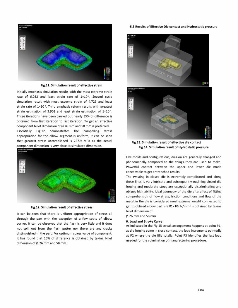
Fig.11. Simulation result of effective strain
Initially emphasis simulation results with the most extreme strain
rate of 6.032 and least strain rate of 1×10⁻⁴. Second cycle
simulation result with most extreme strain of 4.723 and least
strain rate of 1×10⁻⁴. Third emphasis reform results with greatest
strain estimation of 3.902 and least strain estimation of 1×10⁻⁴.
Three iterations have been carried out nearly 35% of difference is
obtained from first iteration to last iteration. To get an effective
component billet dimension of Ø 26 mm and 58 mm is preferred.
Essentially Fig.12 demonstrates the compelling stress
appropriation for the elbow segment is uniform, it can be seen
that greatest stress accomplished is 257.9 MPa as the actual
component dimension is very close to simulated dimension.
Fig.12. Simulation result of effective stress
It can be seen that there is uniform appropriation of stress all
through the part with the exception of a few spots of elbow
corner. It can be observed that the flash is very little and it does
not spill out from the flash gutter nor there are any cracks
distinguished in the part. For optimum stress value of component,
it has found that 16% of difference is obtained by taking billet
dimension of Ø 26 mm and 58 mm.
5.3 Results of Effective Die contact and Hydrostatic pressure
Fig.13. Simulation result of effective die contact
Fig.14. Simulation result of Hydrostatic pressure
Like molds and configurations, dies on are generally changed and
phenomenally composed to the things they are used to make.
Powerful contact between the upper and lower die made
conceivable to get entrenched results.
The twisting in closed die is extremely complicated and along
these lines is very intricate and subsequently outlining closed die
forging and moderate steps are exceptionally discriminating and
obliges high ability. Ideal geometry of the die aftereffect of fitting
comprehension of flow stress, friction conditions and flow of the
metal in the die is considered most extreme weight connected to
get to obliged elbow part is 8.01×10² N/mm2 is obtained by taking
billet dimension of
Ø 26 mm and 58 mm.
6. Load and Stroke Curve As indicated in the Fig 15 streak arrangement happens at point P1,
as die forging come in close contact, the load increments pointedly
at P2 where the die fills totally. Point P3 identifies the last load
needed for the culmination of manufacturing procedure.
084

Fig.15. Result of load v/s stroke in Y-direction
It is observed from Fig.15, flash begins at the stroke estimation of
0.08s and pretty almost at the load of 2.5×101 tons identified as
point P1, die fills absolutely at point P2 with the harsh stroke
estimation of 0.10s and at the induced load estimation of 1×10²
tons. Most prominent load required for the summit of creating
technique is 2×10² tons.
Table 4.2: Simulation results.
Iteration
No.
Dia
(mm)
Flash
%
Effective
Strain
Effective
Stress
N/mm2
Hydrostatic
pressure
N/mm2
1 30 28 6.032 2.57×10² 2.37×10²
2 28 18 4.723 1.97×10² 7.87×10²
3 26 06 3.902 2.09×10² 8.01×10²
7. CONCLUSION The important parameters for creation of the elbow component
have been effectively analyzed through AFDEX simulation tool. The
discriminating part is totally filled and there are no under fill in the
corner area of elbow. There are few spots underneath the center
area and it is in the admissible locale of the last obliged segment.
From three iterations it has been observed that the flash
percentage has reduced from 28% to 6% and the component is
effectively filled in the section. However the third cycle comprises
of the minimum effective stress value of 2.09×10²N/mm2, last
emphasis comprise of slightest compelling strain estimation of
3.902. Hydrostatic pressure finally applied is 8.01×10² N/mm2. The
outcomes can be assessed by leading analyses considering modern
genuine issues. AFDEX simulation software is found to be to a
great degree helpful in simulation process.
In routine system it is exceptionally hard to get exact shape
advancement for production procedure. In spite of the fact that it
takes additional time and expense will be high. Thus proportionate
static load shape optimization procedure ought to be favored, it
diminishes both time and cost of the forging procedure.
Consequently with the help of simulation tool one can explore
advance technique and die parameters in closed die forging and
can enhance the productivity.
References [1]Daniel F. Walczyk, David E. Hardt, 1998,Design and analysis for reconfigurable discrete dies for sheet metal forming, Journal of Manufacturing Systems, 17,pp 436-454. [2] S.Yoshihara, B. Mac Donald, T. Hasegawa, M. Kawahara, H.
Yamamoto, 2004, Design improvement of spin forming of
magnesium alloy tubes using finite element, Journal of Materials
Processing Technology, vol.153–154, 816-820
[3] K.P. Rao, Y.V.R.K. Prasad, K. Suresh, 2011, Materials modeling
and simulation of isothermal forging of rolled AZ31B magnesium
alloy, Journal for Material and Design, vol.32, 2545-2553.
[4] K. Roll, A. Faust, Daimler A, 2008, Forming simulation of high-
strength steels with direction-specific hardening modelling,
Archives of Civil And Mechanical Engineering, vol.3, 107-115.
[5] J.F.O Kane, J.R. Spenceley, R. Taylor, 2000,Simulation as an
essential tool for advanced manufacturing technology
problems,107,412-424.
[6] Hemanth S,Y.Arun kumar,M.S Srinath,Rakshith,Manufacturing
simulation for determing the process parameters on the
quality of forging.
085