advanced multi-gas analysers sample probe manual version 1
TRANSCRIPT


Advanced Multi-Gas Analysers Sample Probe Manual Version 1.0
Protea Sample Probe Manual
– for Use With Protea Gas Analyser Systems
The information contained in this manual is subject to change without notice due to changes in the hardware and software design, specifications and operational procedures of use of Protea analysers and heated sampling lines. Copyright © Protea Ltd. 2017 Last Revision 10/17
WARNING
The gas sampling system parts contain parts that are hot under normal operation. Care should be taken when handling any heated sampling system parts.

Advanced Multi-Gas Analysers Sample Probe Manual Version 1.0
Table of Contents
1. Probe Types ........................................................................................................ 5
1.1 Heated Probe (Fixed Application) ........................................................................... 5
1.2 Heated Probe (Portable Application) ...................................................................... 5
1.3 Unheated Probe ..................................................................................................... 5
2. Fixed Heated Probe (for CEMS applications)......................................................... 6
2.1 Introduction .......................................................................................................... 6
2.2 Safety Instructions ................................................................................................. 7
2.3 Description of Parts................................................................................................ 9
2.4 Fixed Heated Probe Options ................................................................................. 10 2.4.1 Process shut-off valve ............................................................................................................10 2.4.2 Back purge version.................................................................................................................10 2.4.3 Calibration port ......................................................................................................................10 2.4.4 High temperature versions ....................................................................................................10
2.5 Fixed Heated Probe Filter Materials ...................................................................... 11
2.6 Standard Flow Arrangement................................................................................. 11
2.7 Installation Instructions ....................................................................................... 12
2.8 Commissioning/Start-up Checklist ........................................................................ 19
2.9 Standard Operation Notes .................................................................................... 20
2.10 Service (Filter Replacement) ................................................................................. 21
2.11 Service (Faults) .................................................................................................... 22

Advanced Multi-Gas Analysers Sample Probe Manual Version 1.0
3. Portable Heated Probe ...................................................................................... 23
3.1 Introduction ........................................................................................................ 23
3.2 Safety Instructions ............................................................................................... 24
3.3 Description of Parts.............................................................................................. 26
3.1 Portable Heated Probe Filter Materials ................................................................. 27
3.2 Standard Flow Arrangement................................................................................. 27
3.3 Installation Instructions ....................................................................................... 28
3.4 Standard Operation ............................................................................................. 30
3.5 Replacement of Filter ........................................................................................... 31
4. Unheated Probe (for fixed and portable applications) ........................................ 32
4.1 Introduction ........................................................................................................ 32
4.2 Safety Instructions ............................................................................................... 32
4.3 Description of Parts.............................................................................................. 33
4.4 Probe Filter Materials .......................................................................................... 33
4.5 Installation Instructions ....................................................................................... 34
4.6 Standard Operation ............................................................................................. 34

Advanced Multi-Gas Analysers Sample Probe Manual Version 1.1
5 of 35
1. Probe Types
1.1 Heated Probe (Fixed Application)
For Continuous Emissions Monitoring Systems (CEMS) and other process monitoring application requiring fixed and permanent gas measurement, Protea will supply suitable heated probes. This will often include as standard:
DN65/PN6 flange fitting
Self-regulated temperature control, with alarm contact
Span/calibration gas port
G ¾” threaded probe tube fitting
Heated line support bracket And as options:
Back-purge solenoid valve with buffer tank
Heated probe tube
Pre-fitler for sample tube, with or without V-Deflector
1.2 Heated Probe (Portable Application)
For stack emissions testing, temporary process monitoring and research applications, Protea will supply suitable heated probes. This will often include as standard:
Self-regulated temperature control, with alarm contact
Span/calibration gas port
12mm stainless steel sample tube And as standard options:
Heated probe tube
Pre-fitler for sample tube
1.3 Unheated Probe
For any application, fixed or temporary, that does not require a heated sample probe as the process conditions are not hot, Protea will supply our unheated probe. This features as standard:
6mm Swagelok connections
Span/Calibration port
Dilution port
Stainless steel construction with inert coating for sample integrity

Advanced Multi-Gas Analysers Sample Probe Manual Version 1.1
6 of 35
2. Fixed Heated Probe (for CEMS applications) The following manual description is based around the model JES301 sample probe. Alternative probe design could be supplied by Protea based on project requirements, however the basic operation and installation needs will be the same for any heated sample probe.
2.1 Introduction
The heated gas sampling probe is designed for continuous use in extractive sampling systems, even when the sample contains dust and aerosols. Water vapour and high corrosive gases must be kept above their dew point to prevent corrosion and sample degradation prior to the analysis by Protea’s analyser, and a heated probe allows this to be achieved. The sample probe for any given project can be delivered in several versions to meet user specific requirements. As standard, the probe incorporates a non-corrosive heated, replaceable filter element. The filter element is ceramic as standard, or alternatively can be PTFE or glass fibre. The filter element is mounted in an electrically heated stainless steel housing covered by a thermal isolated weather protection enclosure. Filter replacement can be done easily without any tools and without disconnecting the heated sample line. The gas sampling probe can also include options such as a built-in process shut-off valve or back-purge valve. Protea’s standard probe will be supplied with a dedicated calibration or span gas port, so that validation gas can be sampled from the probe to check the analyser reading and response. The probe temperature regulation is done by a maintenance free, electric temperature controller with under temperature alarm that is usually monitored by the Protea gas analyser system. An over temperature protection avoids overheating. A universal mounting clamp is provide to connect the heated sample line to the probe. The standard probe tube material is 316L Stainless Steel. Other probe tube materials are available. For proper selection of various sample pipe constructions and materials please refer to our trained staff. The complete unit consists of the heated filter head, integral temperature controller, mounting flange and installation items. Mounting can be done in a horizontal or vertical position. The probe´s design fits for mounting directly to a standard flange. If the assembly takes place horizontal, the probe should be built in an angle at least between 5° and 15° from the horizontal falling, to allow condensate flow back into the process.

Advanced Multi-Gas Analysers Sample Probe Manual Version 1.1
7 of 35
2.2 Safety Instructions
Gas sample probes are sophisticated devices intended for use by qualified personnel only. It is necessary that this manual is been read and understood by those who will install, use and maintain this equipment.
!CAUTION!
The basic heated sample probes are not suitable for use in hazardous areas. Please contact Protea if a dedicated EX heated probe is required.
When planning, installing, testing, servicing and operating always observe: Operating instructions Other standards and regulations applicable for such applications All recognized rules of technology such as EN standards, VDE0100, Low-Voltage Guidelines EN 60204, Part 1, Machine Guidelines EN 292 and the Accident Prevention Regulations according to BGV A2 Ensure that protection against dangerous body currents are provided as specified in VDE 0100, Part 410 and Part 540 (Grounding and System Grounding) as well as the specifications and the standards listed above. Ensure that the heating probe is installed only outside of explosion-hazard areas. It is not permissible to heat explosive mediums or mediums which release explosive gases when heated! Proper and safe operation of the heating probe assumes that the probe has been carefully transported, stored and properly installed. Ensure that heated probe are installed and put into operation only by qualified personnel. Observe these operating instructions and operation of the device, particularly instructions and notes on routing, the applicable safety precautions for installation and operation of electrical equipment. The probe is operated with mains power, either 110VAC or 2230VAC. During normal operation internal parts of the unit are energized. Disconnect power before opening covers. During operation the housing of the probe can get very hot. Removing the probe housing will expose heated parts.

Advanced Multi-Gas Analysers Sample Probe Manual Version 1.1
8 of 35
Disconnect power before repair or maintenance and ensure that the internal temperature has dropped to a safe level before working on it. Always wear heat resistant gloves. There is burn hazard if necessary precautionary steps are not taken. If these warning notices are ignored possible serious injuries and/or damages may be caused. Only qualified staff who has been trained according to this manual should operate and maintain this instrument. For certain and safe operation the instrument needs to be transported carefully, be part of a well planned application, installed correctly as well as operated and maintained according to these instructions.

Advanced Multi-Gas Analysers Sample Probe Manual Version 1.1
9 of 35
2.3 Description of Parts
2 housing gasket 15 Pivoting frame 42 Screwed cable gland
5 cylinder 17 Extractor 43 Process shut-off ball
valve
6 Filter element screw 21 T - handle 44 Temperature controller
7 Filter element gasket 22 Aluminium cover 45 Sample gas inlet
8 Filter 23 Ring heater element 46 Sample gas outlet
9 Filter retainer 24 Temperature sensor PT
100 47 Back purge port (option)
10 Filter tighting piston 25 Thermal isolation 48 calibration gas port
(option)
11 O-ring B 26 housing 49 Non return valve
12 O-ring A 27 Ground connection pin 50 T-handle for process
shut-off ball valve
13 Bolt 35 housing lock 53 Gasket for sample tube

Advanced Multi-Gas Analysers Sample Probe Manual Version 1.1
10 of 35
2.4 Fixed Heated Probe Options
2.4.1 Process shut-off valve The gas sampling probes JES-301V are equipped with a process shut-off ball valve to shut off the gas flow on the raw gas side. The process shut-off valve is controlled manually, pneumatically or electrically.
2.4.2 Back purge version Periodical back purging of the filter element with instrument air – combined with a surface coated filter element – improves the operating life additionally. It is recommended for small particles exceeding 500 mg/m3 (e.g. in cement industry) and for large particles exceeding 1000 mg/m3. A back purge solenoid valves is fixed directly on the probe with a large passage opening allow efficient back purge results with compact design. These valves are available in several coil voltages. To reduce the pressure shocks occurring during the back purge of the sample gas gas output, Protea supply a pressure reduction valve integrated in the connection fitting of the heated sample line. A back purge valve mounted probe will also often be supplied with a heated or unheated air accumulators with a volume of 2 or 5 liters can be used for back purging. This ensures a constant pressure back purge is delivered. NOTE The Protea Sampling System Control Module (SSCM) is used in fixed analyser systems to control the back purging process. For example, this is usually operated in a “pulsed” mode, giving 3 second pulses of back purge gas to clear the filters.
2.4.3 Calibration port The calibration port allows for easy calibration of the full analysis system; heated probe filter, sample line and analyser
2.4.4 High temperature versions Heated probes can be supplied in versions allowing heated up to temperatures of 315°c.

Advanced Multi-Gas Analysers Sample Probe Manual Version 1.1
11 of 35
2.5 Fixed Heated Probe Filter Materials
2.5.1 Ceramic Ceramic probe filters are provided as standard, unless any other filter material is requested or ordered. Ceramic filters are suitable for the basic range of emissions monitoring of combustion processes and VOCs. They are not suitable for HCl or HF measurements.
2.5.2 Glass Fibre Glass fibres filters are provided are suitable for the ambient, low temperature or VOC-only monitoring processes. They benefit from a very low pressure drop. They are not suitable for HF measurements.
2.5.3 PTFE PTFE filters are provided for waste incineration monitoring applications, for combustion emissions that also require the measurement of acid gases such as HCl and HF. They can have a high pressure drop.
2.6 Standard Flow Arrangement
Basic Internal Flow layout of fixed heated probe, with calibration/span port and back-purge ports
shown
*Options, although Protea supplies Cal port as standard unless not request.

Advanced Multi-Gas Analysers Sample Probe Manual Version 1.1
12 of 35
2.7 Installation Instructions
Please read these installation instructions carefully and observe all points listed when installing the equipment. Failure to observe these installation instructions can result in malfunctions or, under certain conditions, the required EMC Guidelines may not be fulfilled.
2.7.1 Guidelines Disconnect mains before working on electrical part of equipment. • The equipment has to be connected and grounded according to the local rules and regulations. • In order to guarantee safe operation the electronic is equipped with interlocking under temperature monitoring. For reset disconnect and connect power again. • It is highly recommended to use the volt free status contact. Only this assures a reliable operation of the probe. • It is necessary to keep the electronics away from radiant heating (thermal insulation). The ambient temperature must not exceed 60°C. • The flange temperature must not exceed 200°C. Otherwise a change of construction is necessary, eg. use of a thermal spacer. • The probe mounting should always be with a minimum inclination of 5° towards the sampling pipe. This is necessary to prevent a possible flow back from condensate into the probe.

Advanced Multi-Gas Analysers Sample Probe Manual Version 1.1
13 of 35
2.7.2 Mounting
• Mount probe with gasket on the process flange. • Ensure correct mounting angle according technical specification. • 1/8“ NPT male connector at sample gas outlet will be fitted as standard by Protea. This will usually be a 1/8” NPT to 6mm fitting, but other size may be provided. • Attach heated sample line on probe enclosure with moveable PG42 cable conduit or mounting clamp, connect the line with the connector fitting gas-tight. • Connect span gas line to calibration/span port

Advanced Multi-Gas Analysers Sample Probe Manual Version 1.1
14 of 35
2.7.2.1 Vertical Duct

Advanced Multi-Gas Analysers Sample Probe Manual Version 1.1
15 of 35

Advanced Multi-Gas Analysers Sample Probe Manual Version 1.1
16 of 35
2.7.2.2 Horizontal Duct

Advanced Multi-Gas Analysers Sample Probe Manual Version 1.1
17 of 35

Advanced Multi-Gas Analysers Sample Probe Manual Version 1.1
18 of 35
2.7.3 Electrical Installation
1. Check local voltage, frequency and power consumption against type plate. 2. Supply from a RCD protected source, with a protective device to suit the
current load; the sample probe is not equipped with a switch. 3. The equipment has to be connected and additionally grounded with a wire
of sufficient diameter on the ground connection of the housing according to the local rules and regulations.
4. Always operate contacts within specified ratings. For connection of inductive and capacitive loads use suitable protection circuits (f.i. recovery diodes for inductive and serial resistance for capacitive loads). Relays are illustrated in current- less conditions (fail safe).
5. The operator must provide suitable stress relief The two version of heated probe have the following connections. If Protea supply the heated probe as part of a system, Protea will fit a power/alarm lead which will connect via a plug/socket to the supply/alarm cable integrated in a heated line bundle. JES301L
JES301

Advanced Multi-Gas Analysers Sample Probe Manual Version 1.1
19 of 35
2.8 Commissioning/Start-up Checklist
1. Check of the proper installation 2. Review the equipment for damage 3. Make sure that the process shut-off valve (if installed) is closed (i.e. set at
right angle to the longitudinal axis of the probe). 4. Check for leaks.
CAUTION Before switching on sample probe ensure that the operating voltage of the unit and the line voltage are identical.
6. Switch on the power supply of the sample probe. 7. After a lead time of approx. 40 min set temperature will be reached. As
long as the temperature is below the set value the fault indication contact indicates alarm. (Alarm indication: open contact)
8. Turn t-handle of process shut-off valve (if installed) by 90° to open it (ie. t-handle stands in line with probe).
9. Carry out analyser system gas checks as per commissioning checklist for the system
NOTE A small amount of off-gas (smell) on first use is normal and is no reason for a warranty claim. New filter elements and sealings may influence the measurement results. It is recommended to purge the gas sampling probe diligently in heated condition. NOTE With the back purge pulses the filter is cleaned from the inside to the outside. Therefore some dust may remain in the filter housing. This is normal and does not harm the function of the probe in any way.

Advanced Multi-Gas Analysers Sample Probe Manual Version 1.1
20 of 35
2.9 Standard Operation Notes
When operating normally, there are only a few basic operations the heated probe undergoes.
2.9.1 Temperature control (JES301) If the temperature lowers/rises for at least 10 sec. under/over the min./max. of the temperature boundary, the status LED for under/over temperature will be lit. Additionally the status relay is de-energised. If the max. temperature boundary is exceeded, also the SSR heater circuit is galvanically disconnected. The temperature boundary is +20 /-30 k from the adjusted temperature set value. During the heat up sequence under temperature is indicated (LED/Relay) until the temperature set value minus the low boundary of -30 k is reached. For fault suppression during power on a delay of 0,5 sec is equipped.
2.9.2 Heater (JES301) The heater control is done by the control electronics with a solid state relay SSR, with a series wired security relays for safe galvanic isolation in fault condition. For SSR protection a lead fuse rated T6 3 A is wired in series. Heating pulses are displayed by the yellow heater LED.
2.9.3 Alarm Fault (JES301) The status relays is operated in working principle and is equipped with a volt free status contact (energised in good condition). In case of alarm the security relays is also de-energised. If a fault continues uninterrupted for 0 sec the alarm is visually displayed and signalled by the status relay. Short distortions will not be displayed and do not lead to a fault condition. Failure indication is done by lighting up the red LED. The fault code is signalized by short flashing LED pulses between long flash pulses (refer to table).

Advanced Multi-Gas Analysers Sample Probe Manual Version 1.1
21 of 35
2.10 Service (Filter Replacement)
Filter elements, O-rings and gaskets are consumable items and have to be replaced regularly, at least once a year. Ensure that sealing surfaces are clean. NOTE The ceramic filter elements are very fragile by their nature. Handle elements with care and avoid dropping them. CAUTION The housing of the probe may get very hot! Use heat resistant gloves. Take care, in case of process over pressure, explosive and/or toxic gas emanation is possible. To avoid accidents take care for necessary safety precautions in case of service and maintenance. For cleaning or replacing following steps should be carried out. Refer to the diagram in Section 2.3:
1. Close process shut-off valve (if installed as option) 2. Switch off the power supply and wait for cooling down of the probe. 3. Remove the weather protection housing by turning the lock (35) 4. Turn the handle (pos. 21) to pull out the filter element. Swing the pivoting
lever sideways and pull out the support tube with the filter element. 5. Loosen tighten piston (pos. 6) from the support tube (pos. 9). Pull out filter
element and gaskets. 6. Replace filter element (pos. 8) and/or gaskets (pos.7). 7. Clean groove on tighting piston of filter retainer (pos. 10) and remove O-
rings (pos. 11 and 12) with a non-metallic tool (wood or plastic wedge). 8. Replace O-rings. 9. Remount gaskets (pos. 7) and filter element (pos.8). 10. Screw on the filter element-screw (pos. 6). 11. Mount all other parts in reverse sequence.
Advanced Multi-Gas Analysers Sample Probe Manual Version 1.1
22 of 35
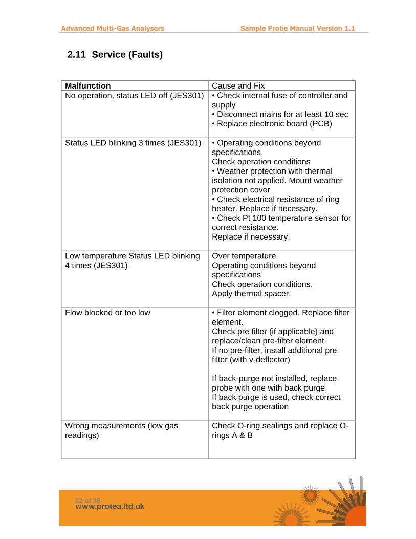
2.11 Service (Faults)
Malfunction Cause and Fix
No operation, status LED off (JES301)
• Check internal fuse of controller and supply • Disconnect mains for at least 10 sec • Replace electronic board (PCB)
Status LED blinking 3 times (JES301)
• Operating conditions beyond specifications Check operation conditions • Weather protection with thermal isolation not applied. Mount weather protection cover • Check electrical resistance of ring heater. Replace if necessary. • Check Pt 100 temperature sensor for correct resistance. Replace if necessary.
Low temperature Status LED blinking 4 times (JES301)
Over temperature Operating conditions beyond specifications Check operation conditions. Apply thermal spacer.
Flow blocked or too low
• Filter element clogged. Replace filter element. Check pre filter (if applicable) and replace/clean pre-filter element If no pre-filter, install additional pre filter (with v-deflector) If back-purge not installed, replace probe with one with back purge. If back purge is used, check correct back purge operation
Wrong measurements (low gas readings)
Check O-ring sealings and replace O- rings A & B

Advanced Multi-Gas Analysers Sample Probe Manual Version 1.1
23 of 35
3. Portable Heated Probe The following manual description is based around the model JPES sample probe. Alternative probe design could be supplied by Protea based on project requirements, however the basic operation and installation needs will be the same for any heated sample probe.
3.1 Introduction
The heated gas sampling probe is designed for portable use in extractive sampling systems, even when the sample contains dust and aerosols. Water vapour and high corrosive gases must be kept above their dew point to prevent corrosion and sample degradation prior to the analysis by Protea’s analyser, and a heated probe allows this to be achieved. The sample probe for any given project can be delivered in several versions to meet user specific requirements. As standard, the probe incorporates a non-corrosive heated, replaceable filter element. The filter element is ceramic as standard, or alternatively can be PTFE or glass fibre. The filter element is mounted in an electrically heated stainless steel housing covered by a thermal isolated weather protection enclosure. Filter replacement can be done easily without any tools and without disconnecting the heated sample line. Protea would always try to supply a probe with a dedicated calibration or span gas port, so that validation gas can be sampled from the probe to check the analyser reading and response. The probe temperature regulation is done by a maintenance free, fully electronic temperature controller with under temperature alarm that is usually monitored by the Protea gas analyser system. An over temperature protection avoids overheating. The complete unit consists of the heated filter head and sampling tube. Mounting can be done in a horizontal or vertical position. If the assembly takes place horizontal, the probe should be built in an angle at least between 5° and 15° from the horizontal falling, to allow condensate flow back into the process.

Advanced Multi-Gas Analysers Sample Probe Manual Version 1.1
24 of 35
3.2 Safety Instructions
Gas sample probes are sophisticated devices intended for use by qualified personnel only. It is necessary that this manual is been read and understood by those who will install, use and maintain this equipment.
!CAUTION!
The basic heated sample probes are not suitable for use in hazardous areas. Please contact Protea if a dedicated EX heated probe is required.
The portable heated gas sampling probe is designed for mobile use in gas analysis systems. Please observe the technical specifications regarding ambient and supply conditions and admissible temperature limits When planning, installing, testing, servicing and operating always observe: Operating instructions Other standards and regulations applicable for such applications All recognized rules of technology such as EN standards, VDE0100, Low-Voltage Guidelines EN 60204, Part 1, Machine Guidelines EN 292 and the Accident Prevention Regulations according to BGV A2 Ensure that protection against dangerous body currents are provided as specified in VDE 0100, Part 410 and Part 540 (Grounding and System Grounding) as well as the specifications and the standards listed above. Ensure that the heating probe is installed only outside of explosion-hazard areas. It is not permissible to heat explosive mediums or mediums which release explosive gases when heated! Proper and safe operation of the heating probe assumes that the probe has been carefully transported, stored and properly installed. Ensure that heated probe are installed and put into operation only by qualified personnel. Observe these operating instructions and operation of the device, particularly instructions and notes on routing, the applicable safety precautions for installation and operation of electrical equipment. The probe is operated with mains power, either 110VAC or 2230VAC. During normal operation internal parts of the unit are energized. Disconnect power before opening covers.
Advanced Multi-Gas Analysers Sample Probe Manual Version 1.1
25 of 35
During operation the housing of the probe can get very hot. Removing the probe housing will expose heated parts. Disconnect power before repair or maintenance and ensure that the internal temperature has dropped to a safe level before working on it. Always wear heat resistant gloves. There is burn hazard if necessary precautionary steps are not taken. If these warning notices are ignored possible serious injuries and/or damages may be caused. Only qualified staff who has been trained according to this manual should operate and maintain this instrument. For certain and safe operation the instrument needs to be transported carefully, be part of a well-planned application, installed correctly as well as operated and maintained according to these instructions.
Advanced Multi-Gas Analysers Sample Probe Manual Version 1.1
26 of 35
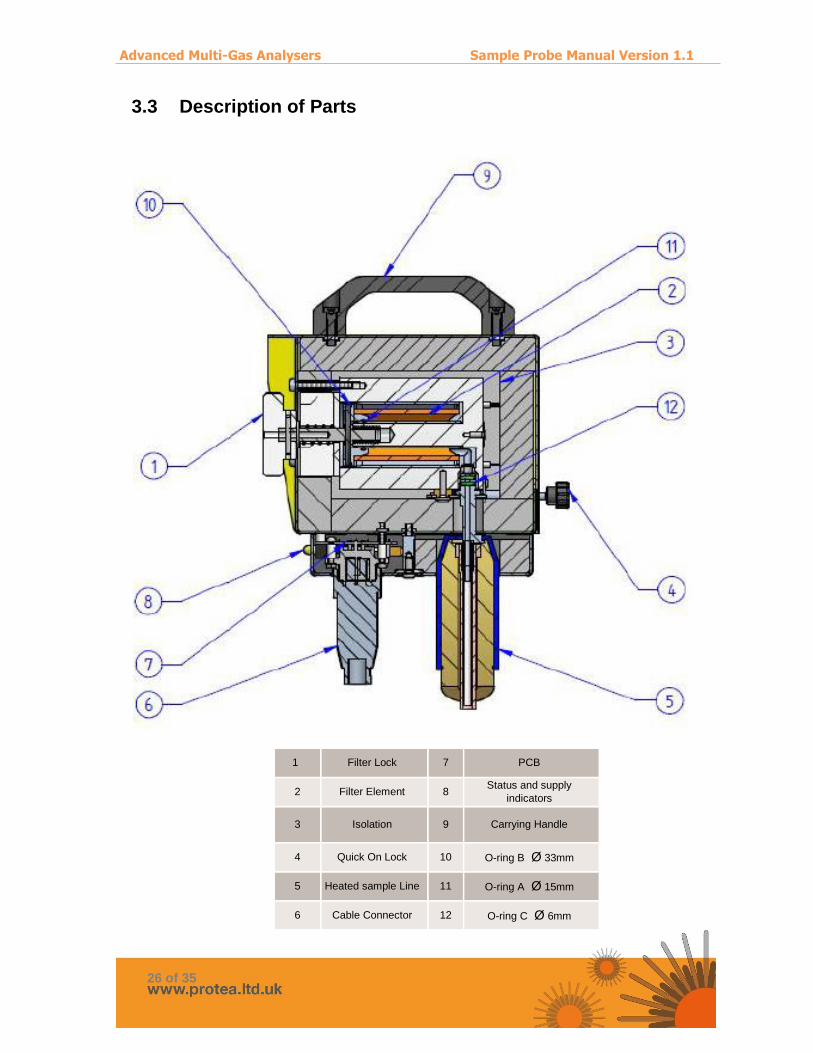
3.3 Description of Parts
1 Filter Lock 7 PCB
2 Filter Element 8 Status and supply
indicators
3 Isolation 9 Carrying Handle
4 Quick On Lock 10 O-ring B Ø 33mm
5 Heated sample Line 11 O-ring A Ø 15mm
6 Cable Connector 12 O-ring C Ø 6mm

Advanced Multi-Gas Analysers Sample Probe Manual Version 1.1
27 of 35
3.1 Portable Heated Probe Filter Materials
3.1.1 Ceramic Ceramic probe filters are provided as standard, unless any other filter material is requested or ordered. Ceramic filters are suitable for the basic range of emissions monitoring of combustion processes and VOCs. They are not suitable for HCl or HF measurements.
3.1.2 Glass Fibre Glass fibres filters are provided are suitable for the ambient, low temperature or VOC-only monitoring processes. They benefit from a very low pressure drop. They are not suitable for HF measurements.
3.1.3 PTFE PTFE filters are provided for waste incineration monitoring applications, for combustion emissions that also require the measurement of acid gases such as HCl and HF. They can have a high pressure drop.
3.2 Standard Flow Arrangement
Basic Internal Flow layout of fixed heated probe, with calibration/span port and back-purge ports
shown
*Options, although Protea supplies Cal port as standard unless not request.

Advanced Multi-Gas Analysers Sample Probe Manual Version 1.1
28 of 35
3.3 Installation Instructions
Please read these installation instructions carefully and observe all points listed when installing the equipment. Failure to observe these installation instructions can result in malfunctions or, under certain conditions, the required EMC Guidelines may not be fulfilled.
3.3.1 Guidelines Disconnect mains before working on electrical part of equipment. • The equipment has to be connected and grounded according to the local rules and regulations. • In order to guarantee safe operation the electronic is equipped with interlocking under temperature monitoring. For reset disconnect and connect power again. • It is essentially necessary to keep the electronics away from radiant heating (thermal insulation). The ambient temperature must not exceed 60°C. • The stack temperature in contact with the probe must not exceed 200°C. Otherwise a change of construction is necessary, eg. use of a thermal spacer. • The probe mounting should always be with a minimum inclination of 5° towards the sampling pipe. This is necessary to prevent a possible flow back from condensate into the probe.

Advanced Multi-Gas Analysers Sample Probe Manual Version 1.1
29 of 35
3.3.2 Mounting • Push in sample pipe and tighten union nut
CAUTION!
Sealing is radial. Tighten stalwart only! NOTE!
Lateral mobility of sample pipe is normal as sealing is radial.
• Mount probe with gasket or universal adapter with aid of some PTFE paste if required on the process flange or sampling hole. • Hang up JPES sample probe with mounting chain. • The universal adapter provided is suitable for nominal pipe sizes up to 60mm. Adapters for larger diameters are available on request. • Connect sample line to the JPES by pulling out the Quick On lock and pushing in the sample line. The sample line will need a mating quick lock adaptor if not a push-fit type.Then connect the other end to the analyser. • Connect span gas line to calibration/span port • Make the electrical connections, supply as well as the status contact for the analyser if to be used.
3.3.3 Electrical Installation
· Check local voltage, frequency and power consumption against type plates of probe, heated line and (if applicable) heated pipe. · Connect mains to supply outlet and JPES temperature status contact to analyser. If needed, connect a 2-pole switch in mains supply. The JPES sample probe is not equipped with a switch. · The operator must provide suitable stress relief for all cables. · Fusing has to be done on site according to local rules and regulations. · Take care of min. bending radius and mechanical support by mounting of heated hose.

Advanced Multi-Gas Analysers Sample Probe Manual Version 1.1
30 of 35
3.4 Standard Operation
1. Ensure proper installation 2. Review the equipment for damage 3. Check for leaks 4. Ensure that unit, filter housing and filter element are clean and no foreign particles are inside. 5. Check the connector is fully pushed in and the collar fully tightened. 6. Caution: Before start up of the sample probe, ensure that the operating voltage of the unit and the line voltage are identical. 7. Switch on the power supply of the JPES sample probe. The yellow LED is turned on. After a lead time of approx. 15 minutes the green LED lights up and the operating temperature is reached. CAUTION! Non-compliance with the control steps can lead to serious hazards or property damage and personal injury! NOTE Any smell or fume at the first time heat up is normal and is no reason for a warranty claim. Calibration gas: 1. Apply calibration gas with minor over pressure/higher flow than sample flow into probe. 2. Excess calibration gas flows off into the process.

Advanced Multi-Gas Analysers Sample Probe Manual Version 1.1
31 of 35
3.5 Replacement of Filter
Filter elements are consumables and have to be replaced regularly. For replacing following steps should be followed:
BURNING DANGER! The housing of the probe can get very hot!
Use heat resistant gloves.
CAUTION! Take care in case of process over pressure, possibility of emission of toxic
gases. To avoid accidents take care for necessary safety precautions in case of service and maintenance.
Refer to diagram in section 3.3
· Switch off the power supply and wait for cooling down of the probe. · Turn away the filter lock (Pos 1) for pulling out the filter element. · ‘Take-off the filter element (Pos 2) from the support tube of filter lock (Pos
1). Pull out filter element and if applicable gaskets. · Replace the filter element (Pos 2) and/or the gaskets (applies only for
sieve filter elements). · Remount the filter element (Pos 2) and if applicable the gaskets. · Screw on the filter element-screw stalwart.

Advanced Multi-Gas Analysers Sample Probe Manual Version 1.1
32 of 35
4. Unheated Probe (for fixed and portable applications)
4.1 Introduction
For some gas measurement applications, where the sample is at low temperature and moisture levels are low/zero, then an unheated sample probe can be supplied. Protea’s standard unheated sample probe is of 316 St. St. construction and is supplied with suitable connection ports for dilution and span gas connections. A pre-fitler can be attached to the probe tip.
4.2 Safety Instructions
Proper and safe operation of the sample probe assumes that the probe has been carefully transported, stored and properly installed. Ensure that probe is installed and put into operation only by qualified personnel. Care should be taken when installing or removing the sample probe from the process. Be aware of process conditions and/or risk of exposure to flue gas. Even though the probe is unheated, the installation location could provide conducted heat to the probe. In this instance during operation the housing of the probe could get very hot. Always wear heat resistant gloves. There is burn hazard if necessary precautionary steps are not taken. If these warning notices are ignored possible serious injuries and/or damages may be caused. Only qualified staff who has been trained according to this manual should operate and maintain this instrument. For certain and safe operation the instrument needs to be transported carefully, be part of a well-planned application, installed correctly as well as operated and maintained according to these instructions.

Advanced Multi-Gas Analysers Sample Probe Manual Version 1.1
33 of 35
4.3 Description of Parts
The probe can be supplied of any suitable length. Check the length is correct for the installation location before attempting to install.
4.4 Probe Filter Materials
A stainless steel sintered pre-filter is installed on the tip of the sample probe. This is of nominal porosity 2µ.

Advanced Multi-Gas Analysers Sample Probe Manual Version 1.1
34 of 35
4.5 Installation Instructions
The probe can be supplied of any suitable length. Check the length is correct for the installation location before attempting to install. The probe should be insert into a suitable connection port on plant with enough clearance (25mm). A 16mm Swagelok nut and loosely fitting PTFE ferrule can be used to secure the probe against the port adaptor.
4.6 Standard Operation
Sample gas is pulled by the analyser from the sample port at the rear of the probe. Any span verification gas can be applied to the span port, for validation of correct sampling by the instrument. If dilution of high concentration samples is needed, dilution gas (N2 or air) can be applied at a known rate into the dilution port. This will also dilute any span gases checked whilst dilution is being applied. Regular checking of the probe for damage, such as from corrosion, is recommended. Regular replacement of the pre-filter is recommended, depending on process conditions.

Advanced Multi-Gas Analysers Sample Probe Manual Version 1.1
35 of 35
END OF MANUAL