advanced pbx data logger - aggsoft.com · how to vie.w.....d..a..t.a...in ... advanced pbx data...
TRANSCRIPT

© 1999-2016 AGG Software
PRINTED MANUAL
All rights reserved. No parts of this work may be reproduced in any form or by any means - graphic, electronic, ormechanical, including photocopying, recording, taping, or information storage and retrieval systems - without thewritten permission of the publisher.
Products that are referred to in this document may be either trademarks and/or registered trademarks of therespective owners. The publisher and the author make no claim to these trademarks.
While every precaution has been taken in the preparation of this document, the publisher and the author assume noresponsibility for errors or omissions, or for damages resulting from the use of information contained in thisdocument or from the use of programs and source code that may accompany it. In no event shall the publisher andthe author be liable for any loss of profit or any other commercial damage caused or alleged to have been causeddirectly or indirectly by this document.
Printed: 21.12.2016
Advanced PBX Data Logger
© 1999-2016 AGG Software
Publisher
AGG Software
Production
© 1999-2016 AGG Softwarehttp://www.aggsoft.com

IContents
© 1999-2016 AGG Software
Table of Contents
Part 1 Introduction 1
................................................................................................................................... 11 About Advanced PBX Data Logger
................................................................................................................................... 22 Glossary
Part 2 License, Registration andtechnical support 3
................................................................................................................................... 31 License
................................................................................................................................... 42 Limitations
................................................................................................................................... 43 How to register
................................................................................................................................... 54 Support
Part 3 Installation 5
................................................................................................................................... 51 System requirements
................................................................................................................................... 52 Installation process
Part 4 Program use 5
................................................................................................................................... 51 Getting started
................................................................................................................................... 72 Introduction
................................................................................................................................... 93 Data flow diagram
................................................................................................................................... 104 Work complete
................................................................................................................................... 105 Useful advices
................................................................................................................................... 116 Configuration
......................................................................................................................................................... 11Serial port
.................................................................................................................................................. 11Serial (COM) port
......................................................................................................................................................... 16Network connection
.................................................................................................................................................. 16TCP/IP settings
......................................................................................................................................................... 24File settings
.................................................................................................................................................. 24File data source
.................................................................................................................................................. 26Folders settings
.................................................................................................................................................. 28Files settings
.................................................................................................................................................. 30Schedule
......................................................................................................................................................... 31TAPI
.................................................................................................................................................. 31Selecting TAPI devices
.................................................................................................................................................. 32Samples
......................................................................................................................................................... 33Additional parameters
.................................................................................................................................................. 33Data view change
.................................................................................................................................................. 34Date/time configuration
.................................................................................................................................................. 35Name and security
......................................................................................................................................................... 37Log files
.................................................................................................................................................. 37Log rotation
.................................................................................................................................................. 39Log f ile access
.................................................................................................................................................. 40Log deletion
Advanced PBX Data LoggerII
© 1999-2016 AGG Software
......................................................................................................................................................... 41Modules
.................................................................................................................................................. 41Introduction & setup
.................................................................................................................................................. 45OPC server
.................................................................................................................................................. 48
How to configure logging to the database using the ODBC Database
module
........................................................................................................................................... 48Preliminary requirements
........................................................................................................................................... 49Option 1
........................................................................................................................................... 52Option 2
.................................................................................................................................................. 56Creating an ODBC data source
.................................................................................................................................................. 58Checking the parser’s operation
.................................................................................................................................................. 59
How to configure logging to the database using the SQL Database Pro
module
........................................................................................................................................... 59Why the SQL Database Pro module is better than ODBC Database
........................................................................................................................................... 59Preliminary requirements
........................................................................................................................................... 59Setup
.................................................................................................................................................. 64Logging additional data from your PBX
.................................................................................................................................................. 66
Possible problems w hen the program running as a service tries to w rite
data to the database
.................................................................................................................................................. 67How to view data in PBX Reports
................................................................................................................................... 687 Program options
......................................................................................................................................................... 68Window view
......................................................................................................................................................... 70Date/time stamp view
......................................................................................................................................................... 71Protocol and errors handling
......................................................................................................................................................... 72Service mode on Windows 2000+
.................................................................................................................................................. 72Configuration
.................................................................................................................................................. 76Window s Vista+ notes
......................................................................................................................................................... 77Restart & Security
Part 5 Serial communications overview 0
................................................................................................................................... 01 RS-232
................................................................................................................................... 02 DB9 (9 pin) RS-232 port pinout
................................................................................................................................... 03 DB25 (25 pin) RS-232 port pinout
................................................................................................................................... 04 RS-232 loopback devices
................................................................................................................................... 05 RS-232 data transfer cables
Part 6 Having problems? 78
................................................................................................................................... 781 Program doesn't run or work
................................................................................................................................... 792 FAQ

1Introduction
© 1999-2016 AGG Software
1 Introduction
1.1 About Advanced PBX Data Logger
The Private Branch eXchange (also called PBX or Private Business Exchange) is a telephoneswitching center that is owned by a private business, compared to one that is owned by thecommon carrier or telephone company. In Europe, the term PABX (Private Automatic BrancheXchange) is often used. The call records from the PBX are called SMDR, CDR, or CIL. Most PBXoffers the following interfaces for collecting data from the PBX:
Serial interface - historically used to print every call record to a serial printer. Now our software cancapture data from this port.Network Port (Listen mode) - where Advanced PBX Data Logger connects to the TCP or UDP port.The PBX then starts streaming information down to the application.Network Port (Server mode) - The PBX connects to Advanced PBX Data Logger.
Advanced PBX Data Logger enables users to record, track and archive phone calls and can captureSMDR or CIR data from RS232, RS845, TCP or UDP ports, custom processes it to your needs, thenextracts variables with the data from data packets and transfers the data to a text or binary file,database, DDE, OPC.
Key features of Advanced PBX Data Logger is:
Capability to log data from multiple PBX at the same time. Our data logger can collect data frommultiple PBX simultaneously. Each PBX may have fully different settings;Universal. Supports more than 50 PBX types and allows to create custom configuration;Variable data receive. Captures CDR and SMDR data from PBX;Extended logging features. Outputs received data without any changes to a log file. Supports date/time stamping and logs rotation;Visualization. The program allows to display all received data in the program window. You cancustomize data view options;Advanced data parser. Allows you to create a custom configurations for PBXs that are not definedby default;Filtering. You may define simple rules or use powerful regular expressions;MS Excel. Data export to ready-to-use MS Excel files;Databases support. Exporting data to MSSQL, MySQL, ODBC-compatible database (MS SQL,Oracle, MS Access, dBase and others);Real-time export capabilities. Advanced PBX Data Logger can run as DDE or OPC server and canpublic all received data;Program message logging. Writing to a protocol file all program messages, so you may diagnoseerrors and warning;Plug-ins. Many plug-in modules that extending program features;Simple, menu-driven step by step set-up Programming is not required to configure the software tocollect data;Supporting various operating systems. It runs under all versions starting from Windows 2000,including 32 and 64-bit systems..Windows service mode. Unlike most other serial logging applications, Advanced PBX Data Loggercan run as a service so that it starts as soon as the operating system starts and doesn't require auser to log in and run it. It will continue to run even as users logon and logoff the workstation.
It is extremely easy to use! The configuration process is fully menu driven and has complete,

2 Advanced PBX Data Logger
© 1999-2016 AGG Software
context sensitive, on-line help. you can easily customize all input to your exact specifications. Onceyou see how easy it is to use Advanced PBX Data Logger, you will never again take data readingsby hand!
Company home page: http://www.aggsoft.com/Software home page: http://www.aggsoft.com/pbx-data-logger.htmSerial port hardware reference: http://www.aggsoft.com/rs232-pinout-cable/
1.2 Glossary
ASCII - An acronym for American Standard Code for Information Interchange. ASCII files are plain,unformatted text files that are understood by virtually any computer. Windows Notepad and virtuallyany word processor can read and create ASCII files. ASCII files usually have the extension .TXT (e.g., README.TXT).
Binary File - A file that contains data or program instructions written in ASCII and extended ASCIIcharacters.
Bit - Binary digit in the binary numbering system. Its value can be 0 or 1. In an 8-bit characterscheme, it takes 8 bits to make a byte (character) of data.
Bytes - A collection of eight bits that represent a character, letter or punctuation mark.
Cable - Transmission medium of copper wire or optical fiber wrapped in a protective cover.
CDR – Call detail record.
Client/Server - A networking system in which one or more file servers (Server) provide services;such as network management, application and centralized data storage for workstations (Clients).
PC - abbreviation for a Personal Computer.
Ports - A connection point for a cable.
Protocol -A formal description of a set of rules and conventions that govern how devices on anetwork exchange information.
SMDR – Station Messaging Detail Record, a way to record telecommunications system activity,also known as Call detail record or CDR.

3License, Registration and technical support
© 1999-2016 AGG Software
2 License, Registration and technical support
2.1 License
Copyright © 1999-2016 AGG Software.All Rights Reserved
SOFTWARE LICENSE
Trial Limited Version
The trial limited version of this software may be used for evaluation purposes at the user's own riskfor a trial period. At the end of the trial period, the user must either purchase a license to continueusing the software, or remove it from his/her system.
The trial limited version may be freely distributed, provided the distribution package is not modified.No person or company may charge a fee for the distribution of Advanced PBX Data Logger withoutwritten permission from the copyright holder.
Licensed Version
On payment of the appropriate license fee, the user is granted a non-exclusive license to use Advanced PBX Data Logger on one computer (i.e. a single CPU), for any legal purpose, at a time.The registered software may not be rented or leased, but may be permanently transferred, if theperson receiving it agrees to terms of this license. If the software is an update, the transfer mustinclude the update and all previous versions.
Registered customer are entitled to free updates during one year from the date of purchase. Itmeans that during one year you can download and install the latest registered versions of AdvancedPBX Data Logger from our site. If you don't want to purchase an updates, you can use the programforever; it will never expire, but you won't be able to use the latest version. If you purchased thesoftware more than one year ago, you are no longer entitled to free upgrade and technical support;however, you can purchase an updates to the latest version at a special, greatly discounted price,and this updates will allow you to have free updates and technical support for another year. The typeof update license must match the type of your existing license.
Whilst every care has been taken in the construction and testing of this software, it is suppliedsubject to the condition that the user undertakes to evaluate the suitability of the control for his/herpurposes. AGG Software makes no representation of the software's suitability for any purpose, andthe user agrees that AGG Software has no responsibility for any loss or damage occasioned by theuse of this software.
TO THE MAXIMUM EXTENT PERMITTED BY APPLICABLE LAW, THE SOFTWARE ANDDOCUMENTATION ARE PROVIDED "AS IS" AND AGG SOFTWARE DISCLAIMS ALL OTHERWARRANTIES AND CONDITIONS, EITHER EXPRESS OR IMPLIED, INCLUDING, BUT NOTLIMITED TO, IMPLIED WARRANTIES OF MERCHANTABILITY, FITNESS FOR A PARTICULARPURPOSE, CONFORMANCE WITH DESCRIPTION, TITLE AND NON-INFRINGEMENT OF THIRDPARTY RIGHTS.

4 Advanced PBX Data Logger
© 1999-2016 AGG Software
TO THE MAXIMUM EXTENT PERMITTED BY APPLICABLE LAW, IN NO EVENT SHALL AGGSOFTWARE BE LIABLE FOR ANY INDIRECT, INCIDENTAL, CONSEQUENTIAL, SPECIAL OREXEMPLARY DAMAGES OR LOST PROFITS WHATSOEVER (INCLUDING, WITHOUTLIMITATION, DAMAGES FOR LOSS OF BUSINESS PROFITS, BUSINESS INTERRUPTION,LOSS OF BUSINESS INFORMATION, OR ANY OTHER PECUNIARY LOSS) ARISING OUT OFTHE USE OR INABILITY TO USE THE SOFTWARE PRODUCT, EVEN IF AGG SOFTWARE HASBEEN ADVISED OF THE POSSIBILITY OF SUCH DAMAGES. IN ANY CASE, AGG SOFTWARE'SCUMULATIVE AND ENTIRE LIABILITY TO YOU OR ANY OTHER PARTY FOR ANY LOSS ORDAMAGES RESULTING FROM ANY CLAIMS, DEMANDS OR ACTIONS ARISING OUT OF ORRELATING TO THIS AGREEMENT SHALL NOT EXCEED THE PURCHASE PRICE PAID FORTHIS LICENSE.
Should any term of these terms and conditions be declared void or unenforceable by any court ofcompetent jurisdiction, such declaration shall have no effect on the remaining terms hereof.
If you do not agree to these conditions you should not install this software.
2.2 Limitations
Program is distributed on shareware terms. This means limited and unavailable secondary programpossibilities, which become valuable or available after program registration. To register the programread here .In trial version of our program are the following limits:
Trial period is limited by 21 days. After that time program won't work until it is registered. Continuous program work time is limited. After set period a message will be displayed andprogram stops its work; All data export modules can handle first 100 records only;
2.3 How to register
The program is distributed on shareware terms. This signifies limited or unavailable many features ofthe program, getting of full value or available after program registration.
If you'd like to be a registered user, to get information about the release of new versions, to usetechnical support and, at last, to get access to disabled functions of the program, register yourcopy. For registration, please, read license agreement .
If you want to buy a program through the Internet visit the registration page of our site. On this pageyou can get the newest information about the registration process, and also find an order link. Afteryou've have the form of order registration. Enter your personal information and choose the mostconvenient payment method for you. Further, you'll get notification and follow the notes in it.
More information about services, registration documents, payment means you can get on our registration page of our site.
4
3

5License, Registration and technical support
© 1999-2016 AGG Software
2.4 Support
Technical questions [email protected]
Common questions [email protected]
Sales questions [email protected]
3 Installation
3.1 System requirements
Windows 2000 Professional - Windowsa 8.1, including x64 and x86 OS, Workstation and ServerOS.
3.2 Installation process
If any beta-version was installed on your computer, remove it.
Quit of the working Advanced PBX Data Logger on installation time.
Run an installation file.
By default, Advanced PBX Data Logger will be installed to the directory "/Programs Files/AdvancedPBX Data Logger" of your system disk, but you can change this path.
In the standard distributive of Advanced PBX Data Logger are no additional modules files, which youcan download from our site.
4 Program use
4.1 Getting started
After you have successfully installed Advanced PBX Data Logger, use the following simple steps toconfigure and run it.
Open the Advanced PBX Data Logger program from the Start Menu.
At program run you get into the main program window (fig. 1.1.1), main elements of which are the

6 Advanced PBX Data Logger
© 1999-2016 AGG Software
main menu, the data window, the program messages list and the status bar. In the data window willbe viewed formatted data processig. In the messages list are logged information, warning and errormessages. The status bar shows current state of the selected data source, interface errormessages and a number of bytes processed. Through the main menu, placed above the datawindow, you can get access to program settings ("Options/Program settings...") and from themenu "File" (fig. 1.1.2) can open an current log-file or clean the data window.
Fig. 1.1.1 Main program window
Fig. 1.1.2. "File" menu item
By default (after installation), the program has not any data sources configured. If the list of datasources on the toolbar is empty, then the program will ask you to add new configuration. Otherwise,the program will fill in the list of data sources and try to start logging of data sources configured.Yes, of course, all your settings are being saved while exiting from the program and loaded while theprogram start.
Set-Up is as Easy as 1-2-3
Step 1. Configure one or more data sources.
Click the "Add configuration" button on the toolbar with big green plus and choose communication
7
7Program use
© 1999-2016 AGG Software
parameters for your device. The "COM Port settings" "IP settings" tab of the "Configurationoptions" dialog lets you configure your settings.
Step 2. Configure log file.
Select the "Log file" header in the configuration dialog window and enable logging for a necessarydata direction.
Step 3. Define how you want the PBX or PABX data to be parsed and translated .
The "Plug-in" button on the toolbar in the main window or "Modules" tab in the dialog window letsyou specify how to parse, filter and format your data to the fit the exact format required by yourapplication. It also lets you pre-define automatic output strings to be sent to an external device.
Now, the program process and exports data from one or multiple data sources.
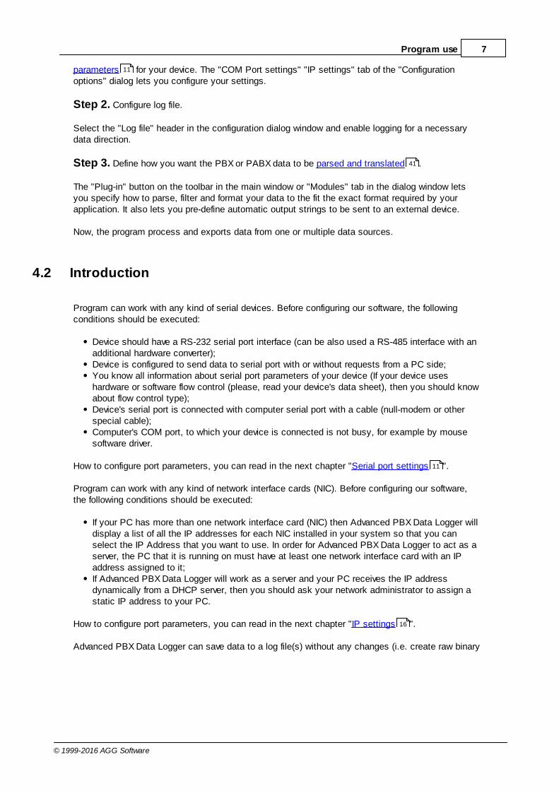
4.2 Introduction
Program can work with any kind of serial devices. Before configuring our software, the followingconditions should be executed:
Device should have a RS-232 serial port interface (can be also used a RS-485 interface with anadditional hardware converter);Device is configured to send data to serial port with or without requests from a PC side;You know all information about serial port parameters of your device (If your device useshardware or software flow control (please, read your device's data sheet), then you should knowabout flow control type);Device's serial port is connected with computer serial port with a cable (null-modem or otherspecial cable);Computer's COM port, to which your device is connected is not busy, for example by mousesoftware driver.
How to configure port parameters, you can read in the next chapter "Serial port settings ".
Program can work with any kind of network interface cards (NIC). Before configuring our software,the following conditions should be executed:
If your PC has more than one network interface card (NIC) then Advanced PBX Data Logger willdisplay a list of all the IP addresses for each NIC installed in your system so that you canselect the IP Address that you want to use. In order for Advanced PBX Data Logger to act as aserver, the PC that it is running on must have at least one network interface card with an IPaddress assigned to it;If Advanced PBX Data Logger will work as a server and your PC receives the IP addressdynamically from a DHCP server, then you should ask your network administrator to assign astatic IP address to your PC.
How to configure port parameters, you can read in the next chapter "IP settings ".
Advanced PBX Data Logger can save data to a log file(s) without any changes (i.e. create raw binary
11
41
11
16

8 Advanced PBX Data Logger
© 1999-2016 AGG Software
log files) or write to log files depending on the parser module selected. In the first case you can viewthe log file with any hex editor and use this data for further analysis and remaking. In the secondcase you can view data with any text editor. You can find more information about log files in the "Logrotation " chapter.
You can watch the data in the data window (fig. 1.1.1 ). The data view is fully customizable. Youcan watch data in decimal, hexadecimal or your own format. How to customize data view you canread in the "Data view " chapter and how to customize program view you can read in the "Windowview " chapter.
The data can be exported or transferred to one or more targets. Most simple way is to configure thelog file rotation. But it is small part of all features of Advanced PBX Data Logger. Advanced PBX DataLogger has many additional modules (so-called plug-ins), that are appreciably extendingpossibilities of the logging software. You can download and install any module supported. Mostmodules are free of charge for our customers. How to install and configure modules you can read inthe "Modules " chapter.
The program and their plug-ins generates many messages and writes they to the list in the mainwindow (fig. 1.1.1 ) and a protocol file, that you can use for administration of the software. Youcan configure types of system messages. More information about it you can read in the "Protocoland errors handling " chapter.
37
5
33
68
41
41
5
71

9Program use
© 1999-2016 AGG Software
4.3 Data flow diagram
This diagram may help you to understand the flow of data within our software and a place of eachmodule. All modules are described in following chapters.
Fig. 1.2.1 Data flow diagram
History:
- Binary flow of data (RAW, unformatted data).
- Parsed data (formatted data). The data flow was been separated to data packets andvariables. Each data packet can be interpreted as a row, and each variable can be interpreted as acolumn.
Wires with other colors mark other relations with unstructured data flow.
10 Advanced PBX Data Logger
© 1999-2016 AGG Software
4.4 Work complete
After program work stop all program settings will be saved in Windows registry. Opened for reading/writing data sources will be automatically closed and will be available for other applications.
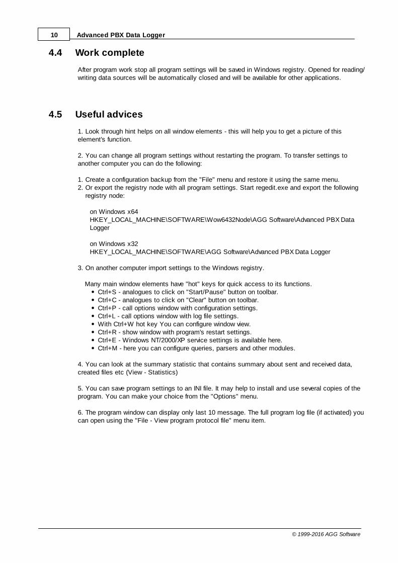
4.5 Useful advices
1. Look through hint helps on all window elements - this will help you to get a picture of thiselement's function.
2. You can change all program settings without restarting the program. To transfer settings toanother computer you can do the following:
1. Create a configuration backup from the "File" menu and restore it using the same menu.2. Or export the registry node with all program settings. Start regedit.exe and export the following
registry node:
on Windows x64 HKEY_LOCAL_MACHINE\SOFTWARE\Wow6432Node\AGG Software\Advanced PBX DataLogger
on Windows x32HKEY_LOCAL_MACHINE\SOFTWARE\AGG Software\Advanced PBX Data Logger
3. On another computer import settings to the Windows registry.
Many main window elements have "hot" keys for quick access to its functions.Ctrl+S - analogues to click on "Start/Pause" button on toolbar.Ctrl+C - analogues to click on "Clear" button on toolbar.Ctrl+P - call options window with configuration settings.Ctrl+L - call options window with log file settings.With Ctrl+W hot key You can configure window view.Ctrl+R - show window with program's restart settings.Ctrl+E - Windows NT/2000/XP service settings is available here.Ctrl+M - here you can configure queries, parsers and other modules.
4. You can look at the summary statistic that contains summary about sent and received data,created files etc (View - Statistics)
5. You can save program settings to an INI file. It may help to install and use several copies of theprogram. You can make your choice from the "Options" menu.
6. The program window can display only last 10 message. The full program log file (if activated) youcan open using the "File - View program protocol file" menu item.

11Program use
© 1999-2016 AGG Software
4.6 Configuration
4.6.1 Serial port4.6.1.1 Serial (COM) port
COM port is short for a serial communication port. Most serial communication softwarecommunicate with a computer through a communication port, and most IBM and IBM-compatiblecomputers support up to four serial ports COM1, COM2, COM3 and COM4. Additional ports can beadded by adding additional hardware.
Advanced PBX Data Logger can manipulate with many serial ports in the same time (up to 255 serialports).
You can open serial ports in Advanced PBX Data Logger software in two modes:
1. Spy mode. In this mode the program monitor data flow on ports selected. In this modeAdvanced PBX Data Logger intercept all data exchange between any Windows application andexternal device;
2. Standard. In this mode the program opens a serial port through Windows API functions, andread/write data from/to a serial port as a regular Windows application. In this mode opens aserial port with exclusive rights and other application will not have access to a serial port.
If one or more port are configured already, then Advanced PBX Data Logger is opening these portsand starting logging. If the port is opened successful, then the status bar in the main windowdisplays a status of this port (fig. 1.1.1 ). But, before you should configure serial port parameters.For minimization of configuration we combined serial ports with same settings to the "Configuration".The configuration can include one or more serial ports with identical settings. For example, if youhave many identical devices, that connected to different serial ports, then you can specify portnumbers in one configuration only. But, if you want to use serial port with different settings, then youshould create more than one configurations.
You can create the new configuration by clicking the "Plus" button in the main window (fig. 1.1.1 )or through the "Options" menu. After you clicked the "Plus" button, the dialog window will be opened(fig. 2.1.2). The dialog window contains few sections with parameters. The "COM port" section isdescribed in this chapter.
You can manage the configuration created with a drop down menu near the "Plus" button (fig. 2.1.1).
5
5
12 Advanced PBX Data Logger
© 1999-2016 AGG Software
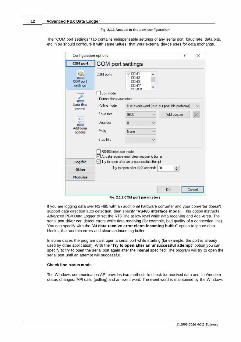
Fig. 2.1.1 Access to the port configuration
The "COM port settings" tab contains indispensable settings of any serial port: baud rate, data bits,etc. You should configure it with same values, that your external device uses for data exchange.
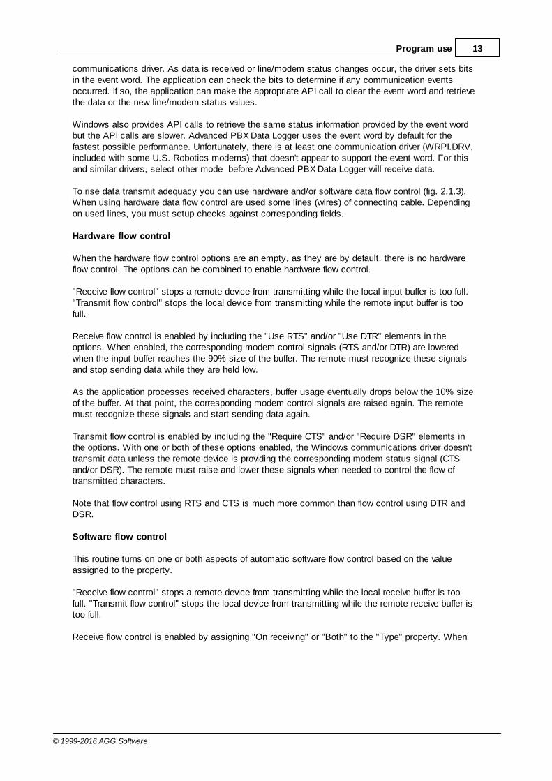
Fig. 2.1.2 COM port parameters
If you are logging data over RS-485 with an additional hardware converter and your converter doesn'tsupport data direction auto detection, then specify "RS485 interface mode". This option instructsAdvanced PBX Data Logger to set the RTS line at low level while data receiving and vice versa. Theserial port driver can detect errors while data receiving (for example, bad quality of a connection line).You can specify with the "At data receive error clean incoming buffer" option to ignore datablocks, that contain errors and clean an incoming buffer.
In some cases the program can't open a serial port while starting (for example, the port is alreadyused by other application). With the "Try to open after an unsuccessful attempt" option you canspecify to try to open the serial port again after the interval specified. The program will try to open theserial port until an attempt will successful.
Check line status mode
The Windows communication API provides two methods to check for received data and line/modemstatus changes: API calls (polling) and an event word. The event word is maintained by the Windows
13Program use
© 1999-2016 AGG Software
communications driver. As data is received or line/modem status changes occur, the driver sets bitsin the event word. The application can check the bits to determine if any communication eventsoccurred. If so, the application can make the appropriate API call to clear the event word and retrievethe data or the new line/modem status values.
Windows also provides API calls to retrieve the same status information provided by the event wordbut the API calls are slower. Advanced PBX Data Logger uses the event word by default for thefastest possible performance. Unfortunately, there is at least one communication driver (WRPI.DRV,included with some U.S. Robotics modems) that doesn't appear to support the event word. For thisand similar drivers, select other mode before Advanced PBX Data Logger will receive data.
To rise data transmit adequacy you can use hardware and/or software data flow control (fig. 2.1.3).When using hardware data flow control are used some lines (wires) of connecting cable. Dependingon used lines, you must setup checks against corresponding fields.
Hardware flow control
When the hardware flow control options are an empty, as they are by default, there is no hardwareflow control. The options can be combined to enable hardware flow control.
"Receive flow control" stops a remote device from transmitting while the local input buffer is too full."Transmit flow control" stops the local device from transmitting while the remote input buffer is toofull.
Receive flow control is enabled by including the "Use RTS" and/or "Use DTR" elements in theoptions. When enabled, the corresponding modem control signals (RTS and/or DTR) are loweredwhen the input buffer reaches the 90% size of the buffer. The remote must recognize these signalsand stop sending data while they are held low.
As the application processes received characters, buffer usage eventually drops below the 10% sizeof the buffer. At that point, the corresponding modem control signals are raised again. The remotemust recognize these signals and start sending data again.
Transmit flow control is enabled by including the "Require CTS" and/or "Require DSR" elements inthe options. With one or both of these options enabled, the Windows communications driver doesn'ttransmit data unless the remote device is providing the corresponding modem status signal (CTSand/or DSR). The remote must raise and lower these signals when needed to control the flow oftransmitted characters.
Note that flow control using RTS and CTS is much more common than flow control using DTR andDSR.
Software flow control
This routine turns on one or both aspects of automatic software flow control based on the valueassigned to the property.
"Receive flow control" stops a remote device from transmitting while the local receive buffer is toofull. "Transmit flow control" stops the local device from transmitting while the remote receive buffer istoo full.
Receive flow control is enabled by assigning "On receiving" or "Both" to the "Type" property. When

14 Advanced PBX Data Logger
© 1999-2016 AGG Software
enabled, an XOff character is sent when the input buffer reaches the level 10% size of the buffer. Theremote must recognize this character and stop sending data after it is received.
As the application processes received characters, buffer usage eventually drops below the level 10%of the buffer. At that point, an XOn character is sent. The remote must recognize this character andstart sending data again.
Transmit flow control is enabled by assigning "On transmitting" or "Both" to the "Type" property. The10% and 90% size of the buffer are not used in this case. When transmit flow control is enabled, thecommunications driver stops transmitting whenever it receives an XOff character. The driver does notstart transmitting again until it receives an XOn character or the user sets software flow control to"None'.
Software data flow control can be setup on receive, transmit or both modes, but so as the greatnumber of device doesn't need data sending, select only control mode "On receive". In case ofactivation of data transmit control remote object (in our case your device) can send special codes,signalizing about data transmit stop or start. On default, received from device character 0x11 Hexsignalizes to COM port driver to start data receive and character 0x13 Hex - to stop data receivefrom device.
Fig. 2.1.3 Data flow control
Spy mode
15Program use
© 1999-2016 AGG Software
In this mode Advanced PBX Data Logger doesn't send and receive any data, and only spies dataexchange, made by other programs.To spy received and sent data open COM port before running the given program. If the given programreceives data over COM port, the data exchange process will be displayed in data receive window.Don't forget to set up check box "Spy mode" to spy data receive by the given program (ifnecessary).
To exit Advanced PBX Data Logger close the given program or stop data exchange over COM port init.
you must close, which data exchange you spies, before closing Advanced PBX Data Logger.
Serial data transfer errors
Line errors can occur during data exchange and displayed in the main program window in the statusbar.
UART receiver parity error - occurs if you configured invalid parity type;UART receiver overrun,UART receiver framing error - occurs if you configured invalid number of stop or data bits;transmit timeout waiting for CTS,transmit timeout waiting for DSR,transmit timeout waiting for RLSD - occurs if you configured invalid hardware flow control or yourserial interface cable isn't wired for hardware flow controltransmit queue is full - occurs if Advanced PBX Data Logger can't send data to remote device; break condition received
Port restart
You can also set the program to initiate the serial interface at the specified time. On some oldversions of the Windows NT operating system it could help to avoid the loss of data when theprogram has been working for a long time without restarting. Please use the "Additional options" tab(fig. 2.1.4)
16 Advanced PBX Data Logger
© 1999-2016 AGG Software
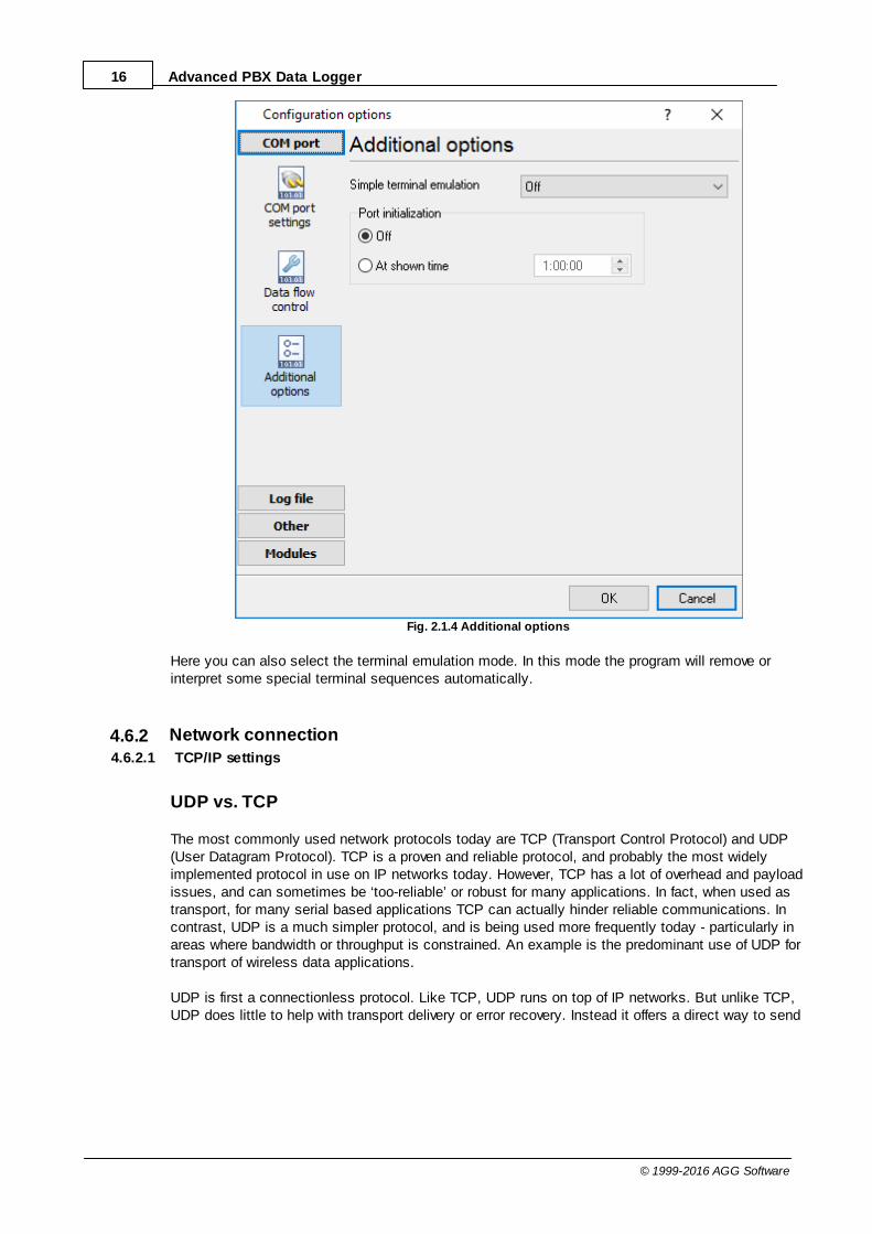
Fig. 2.1.4 Additional options
Here you can also select the terminal emulation mode. In this mode the program will remove orinterpret some special terminal sequences automatically.
4.6.2 Network connection4.6.2.1 TCP/IP settings
UDP vs. TCP
The most commonly used network protocols today are TCP (Transport Control Protocol) and UDP(User Datagram Protocol). TCP is a proven and reliable protocol, and probably the most widelyimplemented protocol in use on IP networks today. However, TCP has a lot of overhead and payloadissues, and can sometimes be ‘too-reliable’ or robust for many applications. In fact, when used astransport, for many serial based applications TCP can actually hinder reliable communications. Incontrast, UDP is a much simpler protocol, and is being used more frequently today - particularly inareas where bandwidth or throughput is constrained. An example is the predominant use of UDP fortransport of wireless data applications.
UDP is first a connectionless protocol. Like TCP, UDP runs on top of IP networks. But unlike TCP,UDP does little to help with transport delivery or error recovery. Instead it offers a direct way to send

17Program use
© 1999-2016 AGG Software
and receive packets, letting the software application manage things like error recovery and dataretransmission. Once primarily used for broadcasting small messages, UDP is now used foreverything from browsers to Instant Messaging, Video, and Voice over IP applications.
While a powerful tool, the downside to using UDP is that there is not ‘connection’ report to know thatyou have end-to-end connectivity. This often makes detecting whether or not a packet is ‘making it’from one place to another quite a hassle.
Client vs Server
Advanced PBX Data Logger can be configured to log data from as many ports that you likesimultaneously on a single PC. The program uses a multi configurations. Each configuration maycontain different settings for each TCP/IP port. Each configuration has a set of TCP/IP parametersthat are described below.
Each port configuration (i.e. TCP/IP connection) in Advanced PBX Data Logger can act as:
1. Client. You will need to specify the remote host IP address and the port number for the TCP/IPserver that you want to connect to. The IP address that you specify in Advanced PBX DataLogger when configuring it as a client may also be either a URL or the name of a computerlocated on your network. For example, if you want to connect to a computer named "Plant1",you can simply enter "Plant1" for the IP address instead of the actual IP address. If you areconfiguring Advanced PBX Data Logger as a client and your network is set up to assign IPaddresses dynamically to each individual workstation, then you may need to use the name ofthe PC that you want to connect to instead of an actual IP address in order to guarantee aconnection;
2. Server. In this mode you should specify the IP address of the local PC will be used and youonly need to specify the port number that you would like to use. If your PC has more than onenetwork interface card (NIC) then Advanced PBX Data Logger will display a list of all the IPaddresses for each NIC installed in your system so that you can select the IP Address that youwant to use. In order for Advanced PBX Data Logger to act as a server, the PC that it is runningon must have at least one network interface card with an IP address assigned to it. In MicrosoftWindows, the TCP/IP protocol can be configured to automatically obtain an IP address from ahost computer. This means that your PC may not have an IP address until it is connected to anetwork server or a host computer. You may need to contact your network administrator toassign an IP address to your PC if you wish to configure a TCP/IP server connection. This isdone in the network settings for the TCP/IP protocol in your control panel.
After you enter the parameters that you would like to use, you must click the "OK" button toestablish a connection between Advanced PBX Data Logger and the TCP/IP port. If the current portconfiguration is set up as a client, it will immediately try to establish a connection to the specifiedremote server. If the server is not available, Advanced PBX Data Logger will continually try toestablish the connection until it is successful. If the port configuration is set up as a server, it willlisten the specified port until a client establishes a connection to it.
If one or more port are configured already, then Advanced PBX Data Logger is opening these portsand starting logging. If the port is opened successful, then the status bar in the main windowdisplays a status of this port (fig. 1.1.1 ). But, before you should configure port parameters thatare described below.
You can create the new configuration by clicking the "Plus" button in the main window (fig. 1.1.1 )or through the "Options" menu. After you clicked the "Plus" button, the dialog window will be opened
5
5
18 Advanced PBX Data Logger
© 1999-2016 AGG Software
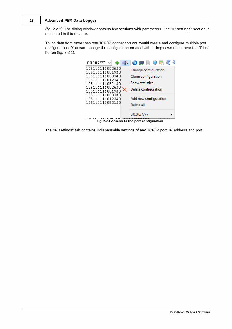
(fig. 2.2.2). The dialog window contains few sections with parameters. The "IP settings" section isdescribed in this chapter.
To log data from more than one TCP/IP connection you would create and configure multiple portconfigurations. You can manage the configuration created with a drop down menu near the "Plus"button (fig. 2.2.1).
Fig. 2.2.1 Access to the port configuration
The "IP settings" tab contains indispensable settings of any TCP/IP port: IP address and port.

19Program use
© 1999-2016 AGG Software
Fig. 2.2.2 TCP/IP parameters
Port
In addition to IP address, you should specify how to connect to a remote machine. Our software canbe thought of as a trunk line with thousands of individual lines (the ports) which are used to connectmachines. Some ports are considered well-known ports. For example, the port typically used fornetwork mail systems (SMTP) is port 25, the telnet port is port 23, the network news server port(NNTP) is typically port 119, and so on. To see a list of well-known ports, inspect the SERVICES filein the Windows directory (for Windows NT it is in the WINNT\SYSTEM32\DRIVERS\ETC directory).The SERVICES file is a text file used by Advanced PBX Data Logger to perform port lookups (whichreturn the service name for the specified port) and port name lookups (which return the port numberfor the specified service name). You can open this file in any text editor to see a list of port numbersand their corresponding service names. While these well-known ports are not set in stone, they aretraditional and their use should be reserved for the service which they represent. When writingnetwork applications, you should select a port number that is not likely to be duplicated by otherapplications on your network. In most cases you can choose a port number other than any of thewell-known port numbers.
The IP address and port number are used in combination to create a socket. A socket is firstcreated and then is used to establish connection between two computers. How the socket is useddepends on whether the application is a client or a server. If an application is a server, it creates thesocket, opens it, and then listens on that socket for computers trying to establish a connection. At

20 Advanced PBX Data Logger
© 1999-2016 AGG Software
this point the server is in a polling loop listening and waiting for a possible connection. A clientapplication, on the other hand, creates a socket using the IP address of a particular server and theport number that the server is known to be listening on. The client then uses the socket to attemptto connect to the server. When the server hears the connection attempt, it wakes up and decideswhether or not to accept the connection. Usually this is done by examining the IP address of theclient and comparing it to a list of known IP addresses (some servers don’t discriminate and acceptall connections). If the connection is accepted, the client and server begin communicating and datais transmitted.
Connection options
If the remote server (in the client mode) or local network interface (in the server mode) is not availableand the "Try to connect after unsuccessful attempt" options is True, then Advanced PBX DataLogger will continually try to establish the connection until it is successful. The program will try toestablish the connection each N seconds that you can specify in the "Next try after XXX seconds"field.
Allowed IP addresses
This option is active in the server mode and allows you to enter one or more IP addresses that haveaccess to the server. IP addresses that are not listed in this fields will be refused by the server. Thisoptions is very useful if you transfer your data over Internet connection or your server PC isconnected to a big corporate network. You can specify multiple addresses - one per row. If you'll notspecify any address here, then Advanced PBX Data Logger will accept connections from all IPaddresses.
Firewall settings
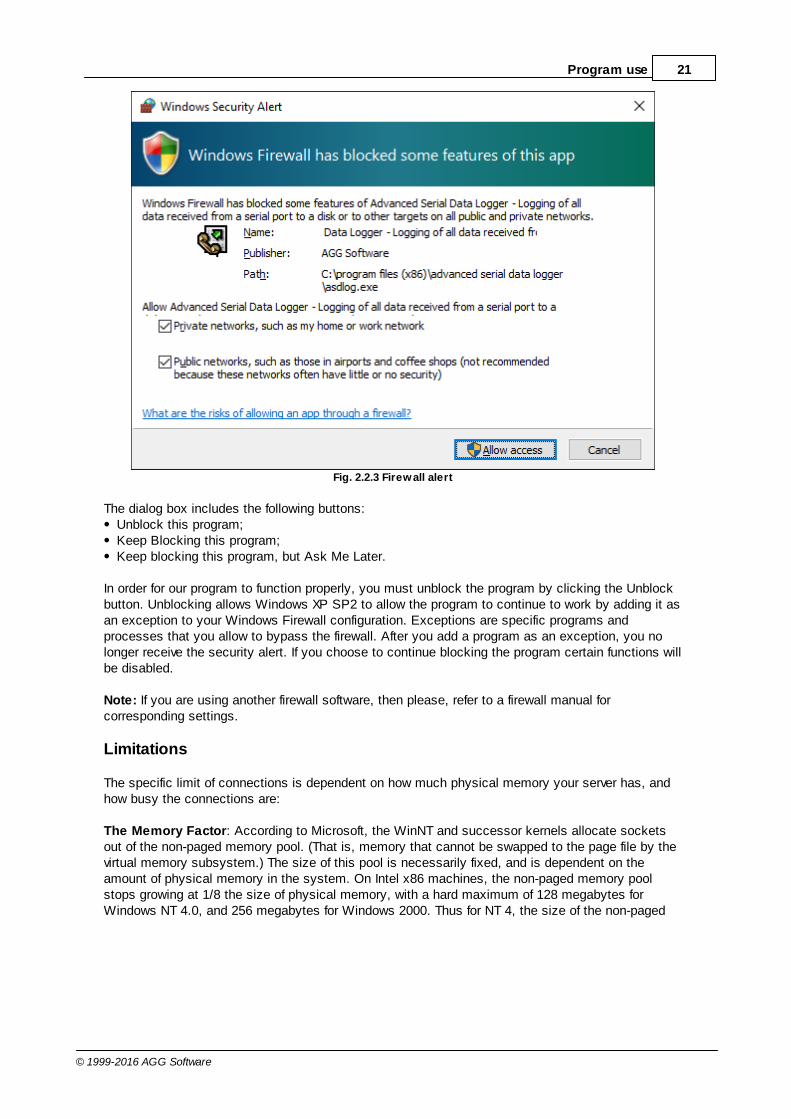
After you install Microsoft Windows XP Service Pack 2 (SP2), our Advanced PBX Data Logger maynot seem to work. Windows Firewall, enabled by default, blocks unsolicited access to yourcomputer via the network and may be blocking the normal operation of the program. To provideincreased security to Windows XP users, Windows Firewall blocks unsolicited connections to yourcomputer. When Windows Firewall detects incoming network traffic that it does not recognize, aSecurity Alert dialog box appears. The security alert dialog box looks like this:
21Program use
© 1999-2016 AGG Software
Fig. 2.2.3 Firewall alert
The dialog box includes the following buttons:Unblock this program;Keep Blocking this program;Keep blocking this program, but Ask Me Later.
In order for our program to function properly, you must unblock the program by clicking the Unblockbutton. Unblocking allows Windows XP SP2 to allow the program to continue to work by adding it asan exception to your Windows Firewall configuration. Exceptions are specific programs andprocesses that you allow to bypass the firewall. After you add a program as an exception, you nolonger receive the security alert. If you choose to continue blocking the program certain functions willbe disabled.
Note: If you are using another firewall software, then please, refer to a firewall manual forcorresponding settings.
Limitations
The specific limit of connections is dependent on how much physical memory your server has, andhow busy the connections are:
The Memory Factor: According to Microsoft, the WinNT and successor kernels allocate socketsout of the non-paged memory pool. (That is, memory that cannot be swapped to the page file by thevirtual memory subsystem.) The size of this pool is necessarily fixed, and is dependent on theamount of physical memory in the system. On Intel x86 machines, the non-paged memory poolstops growing at 1/8 the size of physical memory, with a hard maximum of 128 megabytes forWindows NT 4.0, and 256 megabytes for Windows 2000. Thus for NT 4, the size of the non-paged

22 Advanced PBX Data Logger
© 1999-2016 AGG Software
pool stops increasing once the machine has 1 GB of physical memory. On Win2K, you hit the wallat 2 GB.
The "Busy-ness" Factor: The amount of data associated with each socket varies depending on howthat socket's used, but the minimum size is around 2 KB. Overlapped I/O buffers also eat into thenon-paged pool, in blocks of 4 KB. (4 KB is the x86's memory management unit's page size.) Thusa simplistic application that's regularly sending and receiving on a socket will tie up at least 10 KB ofnon-pageable memory.
The Win32 event mechanism (e.g. WaitForMultipleObjects()) can only wait on 64 event objects at atime. Winsock 2 provides the WSAEventSelect() function which lets you use Win32's eventmechanism to wait for events on sockets. Because it uses Win32's event mechanism, you can onlywait for events on 64 sockets at a time. If you want to wait on more than 64 Winsock event objectsat a time, you need to use multiple threads, each waiting on no more than 64 of the sockets.
If you have more than 64 connection at a time, then we recommend to create multiple configurationin our software (the greenplus button). Each configuration will use different port number and will run in a different thread. Thischange will allow to decrease an influence of Windows limitations.
Additional parameters
The "Additional" tab contains additional settings of a TCP/IP or UDP connection (fig. 2.2.4).
Simple terminal emulation - the program realizes simple implementation of some terminalprotocols. If this emulation is enabled then the program will process some special commands andcharacter sequences.
Following options are effective only in the "TCP/IP server" mode:
Limit of simultaneous connections - you can define number of clients that can connect to theserver at the same time. It allows to optimize a server load with large number of TCP clients.Disconnect inactive clients after (s) - if a client is connected, but didn't send or receive any datawithin the specified time, then the connection with this client will be closed. If you will specify "-1"then the clients will not be disconnected.

23Program use
© 1999-2016 AGG Software
Fig. 2.2.4. Additional parameters
Following options are effective only in the TCP/IP server or client modes:
TCP keep alive mode
A TCP keep-alive packet is a short packet which is sent periodically by the OS to keep theconnection alive. The connection stay alive because those packets and their replies generate smalltraffic on the connection when the application is idle.
Keep-alives can be used to verify that the computer at the remote end of a connection is stillavailable.
It is simply an ACK with the sequence number set to one less than the current sequence number forthe connection. A host receiving one of these ACKs responds with an ACK for the current sequencenumber.
TCP keep-alives can be sent once every KeepAliveTime (defaults to 7,200,000 milliseconds or twohours) if no other data or higher-level keep-alives have been carried over the TCP connection. If thereis no response to a keep-alive, it is repeated once every KeepAliveInterval seconds. KeepAliveIntervaldefaults to 1 second. Some (buggy) routers may not handle keep-alive packets properly.
Our software supports three modes of keep alive (fig 2.2.4):
24 Advanced PBX Data Logger
© 1999-2016 AGG Software
1. Off - the program doesn't use keep alive at all. You can disable keep alive if your network is verystable or your routers doesn't support it.
2. System - the program will use keep alive, but use system values of KeepAliveTime andKeepAliveInterval. These values are stored in the following registry branch:
[HKEY_LOCAL_MACHINE\System\CurrentControlSet\Services\Tcpip\Parameters]KeepAliveTime (32-bit number) = millisecondsKeepAliveInterval (32-bit number) = milliseconds
3. Custom - the program will use keep alive, but you can specify your values of KeepAliveTime andKeepAliveInterval, that are more applicable for your network and system. Note: in our software youshould define these values in seconds.
Note: Some routers may not allow keep-alive TCP packets. In this case the "keep-alive" function willnot work.
Following options are effective only in the server mode (TCP/IP or UDP):
Send client information to the a parser - if this option is activated then program will append asystem header to a data packet about the remote client. It allows the parser to separate datapackets from several clients that send data simultaneously.
4.6.3 File settings4.6.3.1 File data source
About log files
A log file is a file containing records about events in the chronological order.
Logging means the chronological recording of data with varied (customizable) level of details aboutsystems events (errors, warnings, messages). Usually, the data is saved to a file.
Examining the contents of an error log file after failures often makes it possible to understand whatcauses them. Old hardware and software systems use log files to save and store data.
Purpose
The program is used to monitor folders (directories) with log files or separate log files in real time.Once the program detects new data in the log file, it can send notifications to the administrator orexport and archive data from log files. The built-in script and filter tools allow you to single out onlythe events you are interested in from one or several log files. It considerably decreases the load onthe administrator whose job is to maintain several web servers or data servers.
A good example of how to use the program is monitoring a computer where a lot of users cancreate, copy and edit a file. Log files allow you to track all changes and the administrator can controlall operations using the log file. With our program, the administrator can create event types that areto be detected (for example, deleting a file or creating a file with a certain name) and receive animmediate notification about this event as a desktop or e-mail message. The program becomes even

25Program use
© 1999-2016 AGG Software
more useful if you need to control several servers simultaneously.
How the program works
Once started, the program analyzes the list of folders specified in the configuration checking if thesefolders exist. If a folder exists, it is added to the scan list, otherwise it is skipped. Once the datasource is started, the file list is also filled with the initial file size values. Then the program isswitched into one of the scan modes specified in the configuration:
1. "Simple" – simple scan mode. In this mode, the program just analyzes the folders and subfoldersspecified in the configuration for changes in the file.
2. "Shell" – the shell mode uses operating system events when files and folders are created ormodified.
If the program is configured to read data at startup, after the initial processing it will read data fromthe files of the corresponding folders and subfolders and prepare this data for exporting, archiving orsending notifications.
The program monitors new files and folders and starts processing them in both modes. The programalso monitors deleted files and folders and stops processing them.
If a file has just been created or the size of an existing file has changed, the program reads this datafrom the file and passes them on for further processing. The parameters specified in the configurationare used to read data (see "File settings"). If there is a delay set in the configuration before readingthe file and the file changes during this delay, the program delays reading the file for the time of thedelay specified in the configuration. If the file changes again, the reading will be delayed again andso on till the file stops changing. After the program reads the file, it performs one of the followingthree operations with it:
1. The file is deleted;2. The file is cleared, i.e. the file size becomes equal to zero;3. The file is not modified.
The program takes into account the file mask specified in the configuration, i.e. if "*.txt" is specifiedin the configuration, the program will scan and read data only from text file – it will ignore all otherfiles. The program also uses the minimum file size value from the configuration during the scanningprocess. If the file size is less than the specified value, the program does not read the file till the filesize is equal to or larger than the specified value.
The program reads data from the file by blocks whose size is specified in the configuration. Thelarger the block is, the fewer times the program accesses the disk and the better the performanceis, but the requirements to the computer performance are higher.
26 Advanced PBX Data Logger
© 1999-2016 AGG Software
4.6.3.2 Folders settings
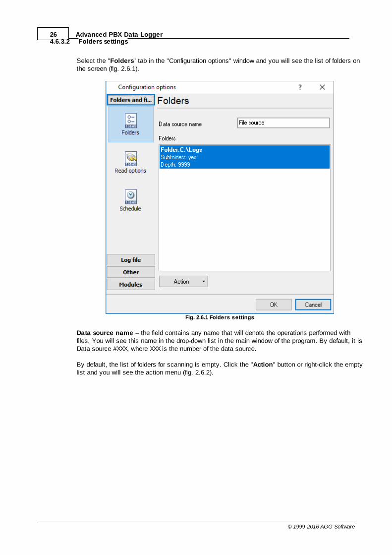
Select the "Folders" tab in the "Configuration options" window and you will see the list of folders onthe screen (fig. 2.6.1).
Fig. 2.6.1 Folders settings
Data source name – the field contains any name that will denote the operations performed withfiles. You will see this name in the drop-down list in the main window of the program. By default, it isData source #XXX, where XXX is the number of the data source.
By default, the list of folders for scanning is empty. Click the "Action" button or right-click the emptylist and you will see the action menu (fig. 2.6.2).
27Program use
© 1999-2016 AGG Software
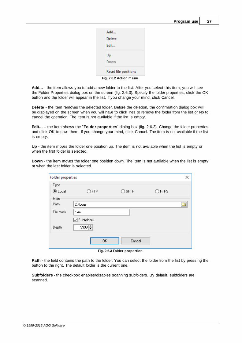
Fig. 2.6.2 Action menu
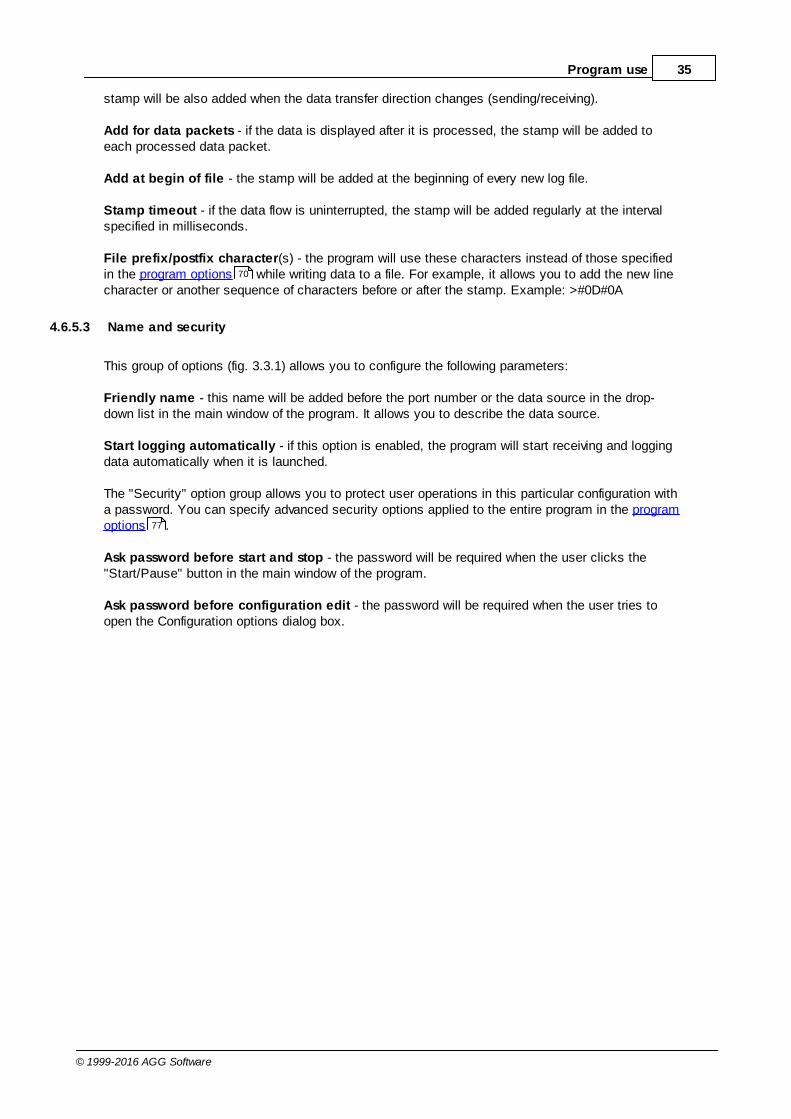
Add... - the item allows you to add a new folder to the list. After you select this item, you will seethe Folder Properties dialog box on the screen (fig. 2.6.3). Specify the folder properties, click the OKbutton and the folder will appear in the list. If you change your mind, click Cancel.
Delete - the item removes the selected folder. Before the deletion, the confirmation dialog box willbe displayed on the screen when you will have to click Yes to remove the folder from the list or No tocancel the operation. The item is not available if the list is empty.
Edit... – the item shows the "Folder properties" dialog box (fig. 2.6.3). Change the folder propertiesand click OK to save them. If you change your mind, click Cancel. The item is not available if the listis empty.
Up - the item moves the folder one position up. The item is not available when the list is empty orwhen the first folder is selected.
Down - the item moves the folder one position down. The item is not available when the list is emptyor when the last folder is selected.
Fig. 2.6.3 Folder properties
Path - the field contains the path to the folder. You can select the folder from the list by pressing thebutton to the right. The default folder is the current one.
Subfolders - the checkbox enables/disables scanning subfolders. By default, subfolders arescanned.

28 Advanced PBX Data Logger
© 1999-2016 AGG Software
Depth - the depth of scanning subfolders. 9999 by default.
Note: The scanning depth is counted from the specified path to the folder. For example:C:\Files\Data\Test - source folderC:\Files\Data\Test\Folder0 - level 1C:\Files\Data\Test\Folder0\Folder1 - level 2etc.
Note: If the specified folder does not exist, you will see an error message on the screen and you willnot be able to save the folder properties so it is recommended to select folder from the list byclicking the button to the right from the Path field.
4.6.3.3 Files settings
Select the "Read options" tab in the "Configuration options" window and you will see the file andscan settings on the screen (fig. 2.6.4).
Fig. 2.6.4 Shell mode
Scan mode - the list allows you to select one of the scan modes: Simple or Shell. In the Simplemode, the program just goes through files in the specified folders and subfolders and checks if the

29Program use
© 1999-2016 AGG Software
the file size has changed. The Shell mode uses operating system events to check changes in thefile size. The program monitors new files and folders and deleted files and folders in both modes. Ifthe operating system does not support the Shell mode, only the Simple mode will be available in thelist. The default mode is Shell.
Shell mode
File mask - the field contains the file mask used to scan files. The program processes only thosefiles that match the mask. For example: *.* - all files are processed, *.txt - only text files areprocessed, *.exe - only executable files are processed. The default is *.*.
Block size (bytes) - the field contains the size of the block (in pixels) used to read data. If the sizeis too small, Data will be read multiple times from the file, which will result in a delay. If the size istoo large, it may also result in a delay. Choose the optimal data block size. The default is 512 bytes.
Min file size - the field defines the minimum size of a file to be processed. There is a list to the rightfrom this field. It contains measurement units: Byte(s), KByte(s) and MByte(s). If the size of the fileis less than that specified in the field with the corresponding measurement unit, it is not processed.The default is 1 Byte(s).
Time after change (msec) - the field contains the delay before the file is read. If the file changesagain during the delay, the reading will be delayed again and so on till the file stops changing. Thedefault is 500 msec.
Read data on start - the checkbox allows the program to read data from the file and pass them tothe kernel at the program startup. The above parameters are used to read data. It is disabled bydefault.
Read and delete - if the option is selected, the program will delete the file after the data is read. Itis not selected by default.
Read and truncate - if the option is selected, the program will clear the file so that its size equalszero after the data is read. It is not selected by default.
Read and don't change - if this option is selected, the program will leave the file unchanged afterthe data is read. It is selected by default.
Simple mode
All parameters are the same as for the Shell mode except for the last option.
Scan interval (sec) - the field contains the scan interval value. The default is 30 sec.

30 Advanced PBX Data Logger
© 1999-2016 AGG Software
4.6.3.4 Schedule
Select the "Schedule" tab in the Configuration Options window and you will see the log file scanschedule settings on the screen (fig. 2.6.5).
Fig. 2.6.5 Schedule
These options allows you to specify:1. The days to scan on (the "Days of week" group);2. The time when to scan (the "Time of day" group). If you specify the interval as 0:00:00-0:00:00,
scanning will be done around the clock.
These options can be useful if, for example, you do not want to scan log files at weekends when thecomputer is off or when the administrator will not see notifications anyway.

31Program use
© 1999-2016 AGG Software
4.6.4 TAPI4.6.4.1 Selecting TAPI devices
This tab contains the list of TAPI devices. The content of this tab depends on a TSP driver for yourPBX. It can be a PBX, trunks lines or extensions. To enable monitoring a device, select it in the list.Note that a device can be compound, i.e. one physical device may represent several logical devices.The "TAPI lines" list contains logical devices.
Fig.1 TAPI lines list
Split calls – This feature allows to produce records for each stage of a call (e.g. begin, dialing,ringing). Call splitting is not necessary to receive a record on each transfer. The transfer will belogged automatically.
Try to open again after a failed attempt – if this option is enabled, the program will wait till thedevice appears and automatically start logging data from it in case the TAPI device is connectedand disconnected periodically.

32 Advanced PBX Data Logger
© 1999-2016 AGG Software
4.6.4.2 Samples
How to connect Panasonic PBX through USB
1. Connect your PBX using an USB cable.2. Install the USB driver for your PBX and OS (x64 or x86). Please, verify that the driver is installedsuccessfully.3. Install TAPI Service Provider (TSP)
Please choose your PBX:
Panasonic KX-TDA/TDE/NCP/NS TSP v4.2 x86 (16,5 MB)
TSP v4.2 x64 (20,6 MB)
Panasonic KX-Series TSP Installation Manual (961 KB)
Panasonic KX-TDA, Panasonic KX-TVM,Panasonic KX-TE
USB-driver (610KB v2.3.0.0)
Panasonic KX-TD TSP (1,6MB v1.2.177)
4. Reboot your computer5. Add the new "TAPI" data source in our software (by clicking the "Plus" button)

33Program use
© 1999-2016 AGG Software
4.6.5 Additional parameters4.6.5.1 Data view change
Fig. 3.1.1. Data view
Data view settings, that can be configured on the "Data view" tab:
1. View characters with code - the program can interpret and decode bytes as characters. Youcan select decoding mode for each characters range. If the range doesn't have thecorresponding character, that's why these data can be displayed only in hexadecimal anddecimal code.
2. You can set up data byte display users format. The directive %d shows to display an decimalcode, the directive %x - hex code. You can set any framing characters before/after the userformat.
3. Highlight data sent on screen - string with sent data will be highlighted by the set color.4. Character set - allows to define the character set of incoming data. Windows - Windows ANSI
character set, DOS - OEM character set.5. Data source custom color - if you've created several configurations then you can define a
custom color for each data source that allows to distinguish data flows on the "All data" page inthe main window.
6. Split strings by data timeout - this option allows to visually split data packets in the program

34 Advanced PBX Data Logger
© 1999-2016 AGG Software
window. A data packets that will be received after the specified interval will be showed on a newline. If this value is set to 0 then data packets will not split.
7. Split continuous data blocks large than - this option allows to visually split continuous dataflow in the program window. The program will show data from a new line every specified interval.
8. Split by characters - this option allows to visually split continuous data flow in the programwindow using the specified symbols. For example (fig. 3.1.1), the program will use a characterwith the 0Ah hexadecimal code that is equal to the "LF" ASCII code.
4.6.5.2 Date/time configuration
This group of options (fig. 3.2.1) allows you to configure how data and time stamps appear in the logfile and on the screen. You can configure the stamp format in the program options .
Fig. 3.2.1 Time stamp configuration
Add to display output for data sent - the time stamp will be added for the sent data displayed onthe screen. The stamp will be added according to the timeout (if the data flow is uninterrupted) orwhen a data packet is sent.
Add to display output for data received - the same but for the received data.
Add if data direction has been changed - if the program is sending and receiving data, the time
70
35Program use
© 1999-2016 AGG Software
stamp will be also added when the data transfer direction changes (sending/receiving).
Add for data packets - if the data is displayed after it is processed, the stamp will be added toeach processed data packet.
Add at begin of file - the stamp will be added at the beginning of every new log file.
Stamp timeout - if the data flow is uninterrupted, the stamp will be added regularly at the intervalspecified in milliseconds.
File prefix/postfix character(s) - the program will use these characters instead of those specifiedin the program options while writing data to a file. For example, it allows you to add the new linecharacter or another sequence of characters before or after the stamp. Example: >#0D#0A
4.6.5.3 Name and security
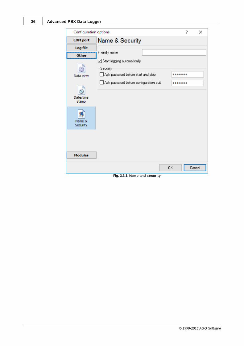
This group of options (fig. 3.3.1) allows you to configure the following parameters:
Friendly name - this name will be added before the port number or the data source in the drop-down list in the main window of the program. It allows you to describe the data source.
Start logging automatically - if this option is enabled, the program will start receiving and loggingdata automatically when it is launched.
The "Security" option group allows you to protect user operations in this particular configuration witha password. You can specify advanced security options applied to the entire program in the programoptions .
Ask password before start and stop - the password will be required when the user clicks the"Start/Pause" button in the main window of the program.
Ask password before configuration edit - the password will be required when the user tries toopen the Configuration options dialog box.
70
77
36 Advanced PBX Data Logger
© 1999-2016 AGG Software
Fig. 3.3.1. Name and security
37Program use
© 1999-2016 AGG Software
4.6.6 Log files4.6.6.1 Log rotation
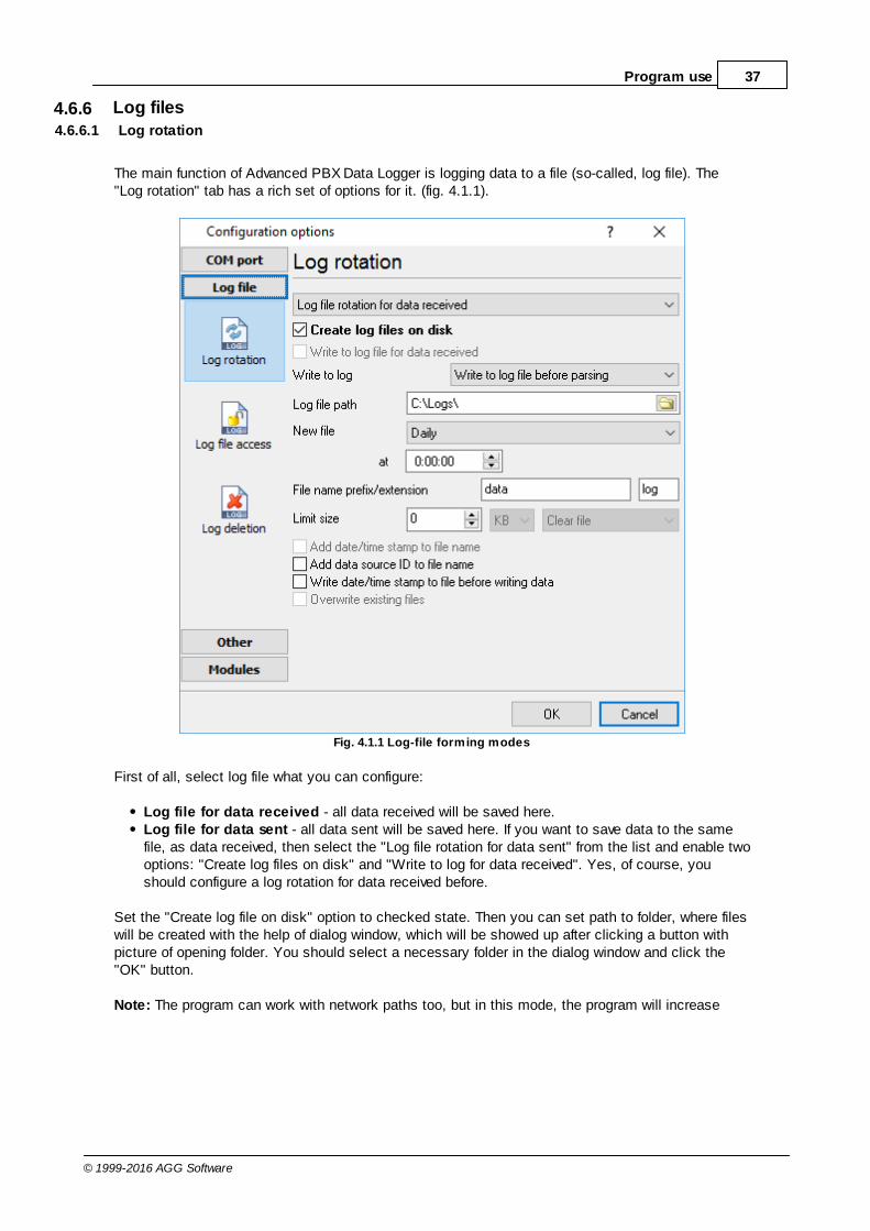
The main function of Advanced PBX Data Logger is logging data to a file (so-called, log file). The"Log rotation" tab has a rich set of options for it. (fig. 4.1.1).
Fig. 4.1.1 Log-file forming modes
First of all, select log file what you can configure:
Log file for data received - all data received will be saved here.Log file for data sent - all data sent will be saved here. If you want to save data to the samefile, as data received, then select the "Log file rotation for data sent" from the list and enable twooptions: "Create log files on disk" and "Write to log for data received". Yes, of course, youshould configure a log rotation for data received before.
Set the "Create log file on disk" option to checked state. Then you can set path to folder, where fileswill be created with the help of dialog window, which will be showed up after clicking a button withpicture of opening folder. You should select a necessary folder in the dialog window and click the"OK" button.
Note: The program can work with network paths too, but in this mode, the program will increase

38 Advanced PBX Data Logger
© 1999-2016 AGG Software
data flow over a network and can be failed with exceptional errors.
A log file name can be stamped with date and time. In this case a new log file is createdperiodically. The time stamp format depends on the selected period. For instance, if the "File nameprefix" field is set to "sample", the "File extension" field to "log" and the "File name format"option is "Daily", then each log file created will have the format "sampleYYYYMMDD.log". On March21st, 2003, the log file will be "sample20030321.log". Please, note, that the final extension (after thefinal period), remains at the end of the file name.
Log rotation mode is defined by the following key parameters:
File name prefix - text string, which will be added at file name beginning;File name extension - text string, which will be a file extension (characters after dot);
Limit size - the "Limit size" field specify the maximum size in kilobytes of any log file. If you'llspecify zero size, then the file size will not limited. You may select from the following modes:1. Clear file - if the log file size will exceed the limit specified, then the log file content will be
deleted and file filling will start from beginning.2. Rename old - if the log file size will exceed the limit specified then the existing log file will be
renamed.3. Shift (no threshold) - the older data over the limit specified will removed from the log file.4. Shift (with threshold). In this mode the program will wait when the file size will exceed the limit
specified + the threshold value. After this, the older data over the limit specified will removed fromthe log file.
If the program works continuous for a long time, it is possible that the log file will have large size andthis file will be inconvenient for looking and analysing. For this there is the possibility to create filesin dependence with the time on PC. You can select one variant predefined or set up new one:
Daily - file will be created with name containing prefix, and date in format DDMMYYYY, whereDD is two-digit day sign, MM is two-digit month sign and YYYY is four digits of the current year.The file name extension will be added at the end of file;Monthly - file will be created with name containing prefix, and date in MMYYYY format. The filename extension will be added at the end of file;Each data packet in different file - in this mode the program splits data flow to a different file.In this mode you should configure the parser or the program will split a data by timeout about300 ms.Don't create new file - in this mode the program will write all data to one file. It isrecommended for a small data flow. Otherwise your log file will be too big and a performance ofthe program will fall down;User's format - file will be created with name containing prefix and date in showed by youformat (for example, DDMMYYYY). The file name extension will be added at the end of file. Thefile may not contain format signs, then file name will be constant. You should not usecharacters, that the OS doesn't allows in file name, such as "/,\.*,?" and some others;Weekly - create a new file every week. The file name will contains a week number;After data timeout - the program will create a new file if the program didn't receive any data atthe specified interval.Hourly - file will be created with name containing prefix, and date in format YYYYMMDDHH,where HH is two-digit hour sign, DD is two-digit day sign, MM is two-digit month sign and YYYYis four digits of the current year. The file name extension will be added at the end of file;Constantly named file - the current log file will have a constant name. When creating a newfile the existing log file will be saved using the new file name that will contain a data and time

39Program use
© 1999-2016 AGG Software
stamp.
Date and time formatting codes:
d - day, not adding null(1-31).dd - day ,adding null(01-31).ddd - day of the week in text form(Mon-Sat) according to standard, set on this computer.dddd - day of the week in full text form(Monday-Saturday) according to standard, set on thiscomputer.m - month, not adding null(1-12).mm - month, adding null (01-12).mmm - month in text form(Jan-Dec) according to standard, set on this computer.mmmm - month in full text form (January- December) according to standard, set on this computer.yy - year in the form of two last digits(00-99)yyyy - year in the form of four last digits (0000-9999).h - hours, not adding null (0-23).hh - hours, adding null (00-23).n - minutes, not adding null (0-59)nn - minutes, adding null (00-59).s - seconds, not adding null (0-59).ss - seconds, adding null (00-59).
Example: you want to create log file every hour. It is desired that file name starts from "sample_log"and the file extension "txt".
Answer: set file prefix = sample_log_, file extension= txt (without dot!). In file name format showHHDDMMYYYY. Now file will be created every hour. Naturally, you can set any formattingcharacters combination, described higher.
If you want to access to a log file while the program work, then you should configure access modesettings for the log file in the next chapter.
Add date/time stamp to file name - this option is available for modes #4 and #7 and allows to adddate and time to the file name.
Add data source ID to file name - if this options is activated then then the program will append thedata source name at the beginning of the file name. For example, COM1-sample20030321.log.
Write data/time stamp to file before writing data - if this options is activated then then theprogram will write a date/time stamp to a file before each data portion.
Overwrite existing files - this option is available for modes #4 and #7 and allows to delete anexisting log file before creating a new log file.
4.6.6.2 Log file access
During work can be such situations, when it is necessary to get access to a file with current data(current log file) from other applications (for example, for data processing). But while you areaccessing the current log file Advanced PBX Data Logger can't write data to a log file and all data atthis moment will be lost. We recommend to use a temporary file for data storage. It is most safeway. (fig. 4.2.1).
39
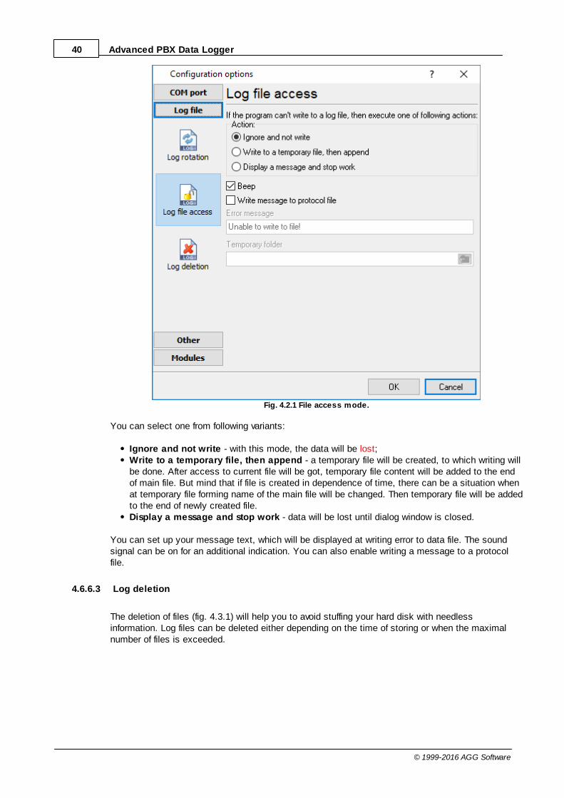
40 Advanced PBX Data Logger
© 1999-2016 AGG Software
Fig. 4.2.1 File access mode.
You can select one from following variants:
Ignore and not write - with this mode, the data will be lost;Write to a temporary file, then append - a temporary file will be created, to which writing willbe done. After access to current file will be got, temporary file content will be added to the endof main file. But mind that if file is created in dependence of time, there can be a situation whenat temporary file forming name of the main file will be changed. Then temporary file will be addedto the end of newly created file.Display a message and stop work - data will be lost until dialog window is closed.
You can set up your message text, which will be displayed at writing error to data file. The soundsignal can be on for an additional indication. You can also enable writing a message to a protocolfile.
4.6.6.3 Log deletion
The deletion of files (fig. 4.3.1) will help you to avoid stuffing your hard disk with needlessinformation. Log files can be deleted either depending on the time of storing or when the maximalnumber of files is exceeded.
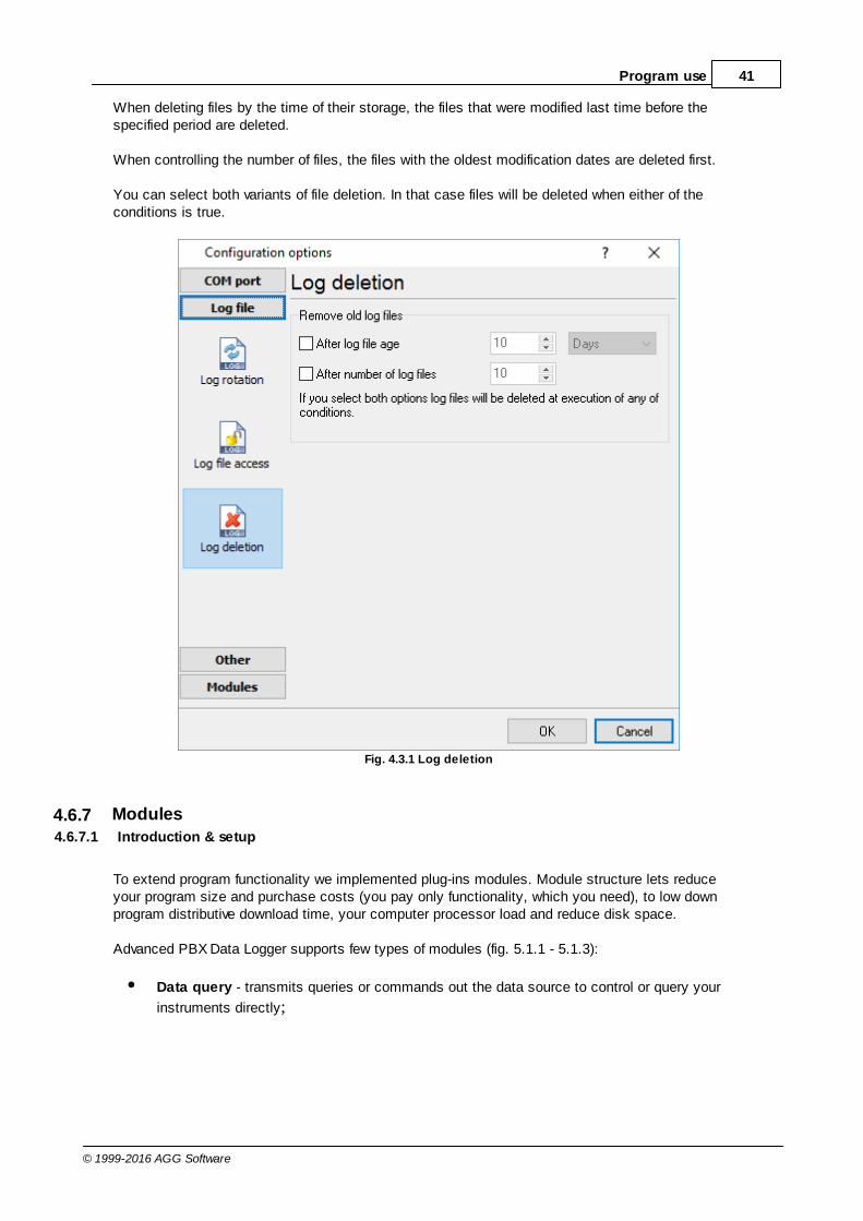
41Program use
© 1999-2016 AGG Software
When deleting files by the time of their storage, the files that were modified last time before thespecified period are deleted.
When controlling the number of files, the files with the oldest modification dates are deleted first.
You can select both variants of file deletion. In that case files will be deleted when either of theconditions is true.
Fig. 4.3.1 Log deletion
4.6.7 Modules4.6.7.1 Introduction & setup
To extend program functionality we implemented plug-ins modules. Module structure lets reduceyour program size and purchase costs (you pay only functionality, which you need), to low downprogram distributive download time, your computer processor load and reduce disk space.
Advanced PBX Data Logger supports few types of modules (fig. 5.1.1 - 5.1.3):
Data query - transmits queries or commands out the data source to control or query your
instruments directly;

42 Advanced PBX Data Logger
© 1999-2016 AGG Software
Data parser - data parser that allows you to parse, filter and format more complex data from
more sophisticated devices. Some of the advanced features of the parser are the ability towork with raw binary or hex data;
Data filter - data filters allow you to filter your data and modify values of parser variables;
Data export (fig.11) - Advanced PBX Data Logger has many modules for passing serial data
directly to other applications, such as as keystrokes where incoming data is passed to otherprograms as a sequence of keys, as DDE Server that passes data to other programs usingDynamic Data Exchange, ODBC for exporting data to a database and many others;
Events handling (fig.12) - an external plug-ins used to handle events generated by the
Advanced PBX Data Logger software. Once an event occurs (for example: "Data source isopened" or "Configuration changed"), the plug-in creates a text message using the specifiedtemplate and sends a notification, do some actions, such as execute programs, scripts andetc. The form of the notification or actions depends on the plug-in settings.
Fig. 5.1.1. Activating plug-ins
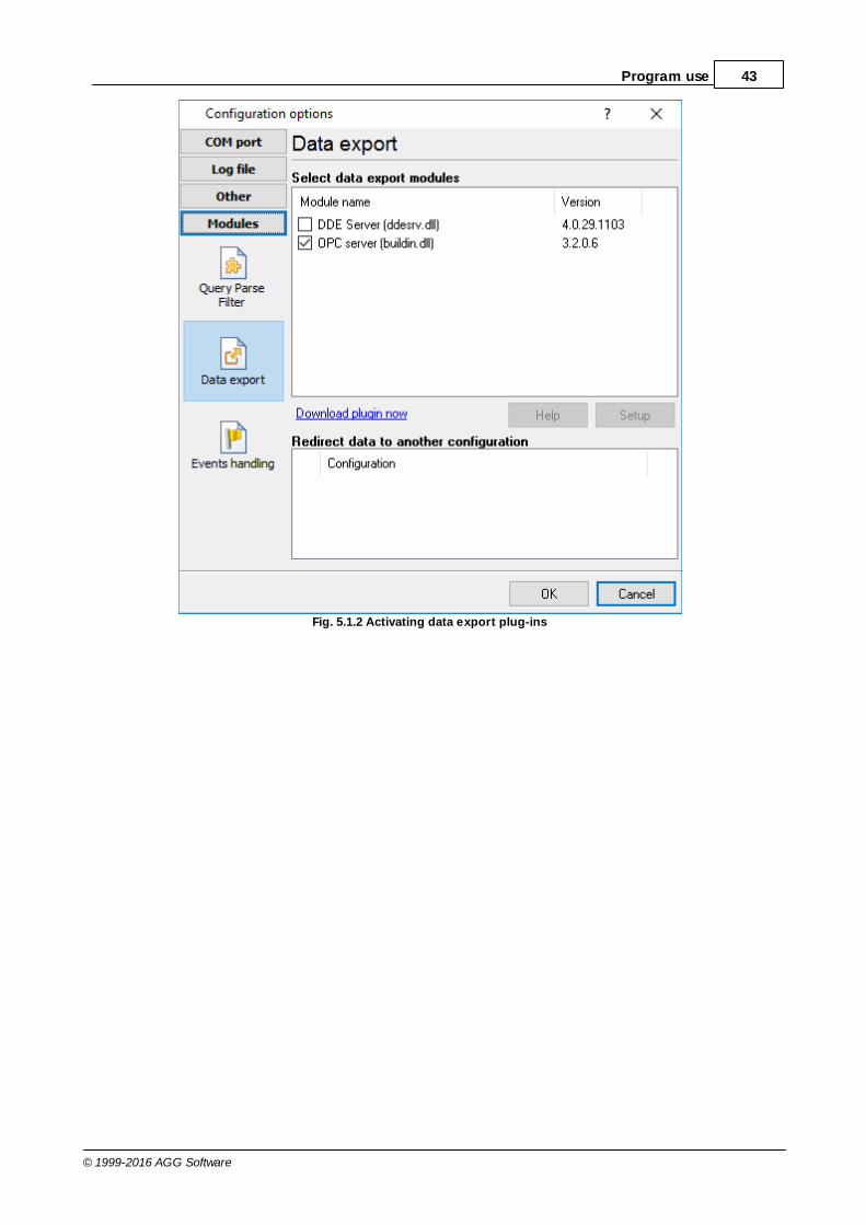
43Program use
© 1999-2016 AGG Software
Fig. 5.1.2 Activating data export plug-ins
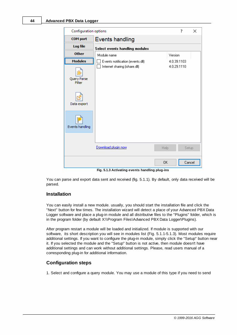
44 Advanced PBX Data Logger
© 1999-2016 AGG Software
Fig. 5.1.3 Activating events handling plug-ins
You can parse and export data sent and received (fig. 5.1.1). By default, only data received will beparsed.
Installation
You can easily install a new module. usually, you should start the installation file and click the"Next" button for few times. The installation wizard will detect a place of your Advanced PBX DataLogger software and place a plug-in module and all distributive files to the "Plugins" folder, which isin the program folder (by default X:\\Program Files\Advanced PBX Data Logger\Plugins).
After program restart a module will be loaded and initialized. If module is supported with oursoftware, its short description you will see in modules list (Fig. 5.1.1-5.1.3). Most modules requireadditional settings. If you want to configure the plug-in module, simply click the "Setup" button nearit. If you selected the module and the "Setup" button is not active, then module doesn't haveadditional settings and can work without additional settings. Please, read users manual of acorresponding plug-in for additional information.
Configuration steps
1. Select and configure a query module. You may use a module of this type if you need to send

45Program use
© 1999-2016 AGG Software
some data to your device (for example, initialization strings or request strings).2. Select and configure a parser module. This step is necessary, because filter and export modules
can use parsed data only. If you didn't select the parser module, then you can't configure the datafilter and data export modules.
3. Activate and configure data export modules. You can select one or more modules simultaneously.The program will use selected modules simultaneously. Please, note, the program can' use thedata export module, if you didn't configure the parser module.
4. Activate and configure event modules. You can select one or more modules simultaneously.
4.6.7.2 OPC server
Since the version 2.1.1 Advanced PBX Data Logger has an internal OPC server. It means, that anyOPC compatible client application can get data from Advanced PBX Data Logger without anyadditional software. For connecting to the OPC server our OPC server has an unique attributes (Fig.5.2.1). Before using the OPC server on your PC you should download and install the OPC CoreComponents Redistributable from www.opcfoundation.org (registration required).
Fig. 5.2.1 OPC server parameters
Advanced PBX Data Logger are parsing all incoming data to one or more variables and OPC clientare getting it (fig. 5.2.2). After connecting to the OPC server you will get list of all variables.
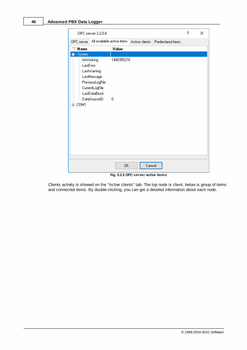
46 Advanced PBX Data Logger
© 1999-2016 AGG Software
Fig. 5.2.2 OPC server active items
Clients activity is showed on the "Active clients" tab. The top node is client, below is group of itemsand connected items. By double-clicking, you can get a detailed information about each node.
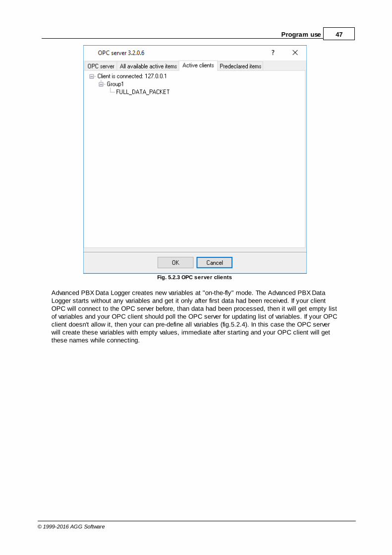
47Program use
© 1999-2016 AGG Software
Fig. 5.2.3 OPC server clients
Advanced PBX Data Logger creates new variables at "on-the-fly" mode. The Advanced PBX DataLogger starts without any variables and get it only after first data had been received. If your clientOPC will connect to the OPC server before, than data had been processed, then it will get empty listof variables and your OPC client should poll the OPC server for updating list of variables. If your OPCclient doesn't allow it, then your can pre-define all variables (fig.5.2.4). In this case the OPC serverwill create these variables with empty values, immediate after starting and your OPC client will getthese names while connecting.
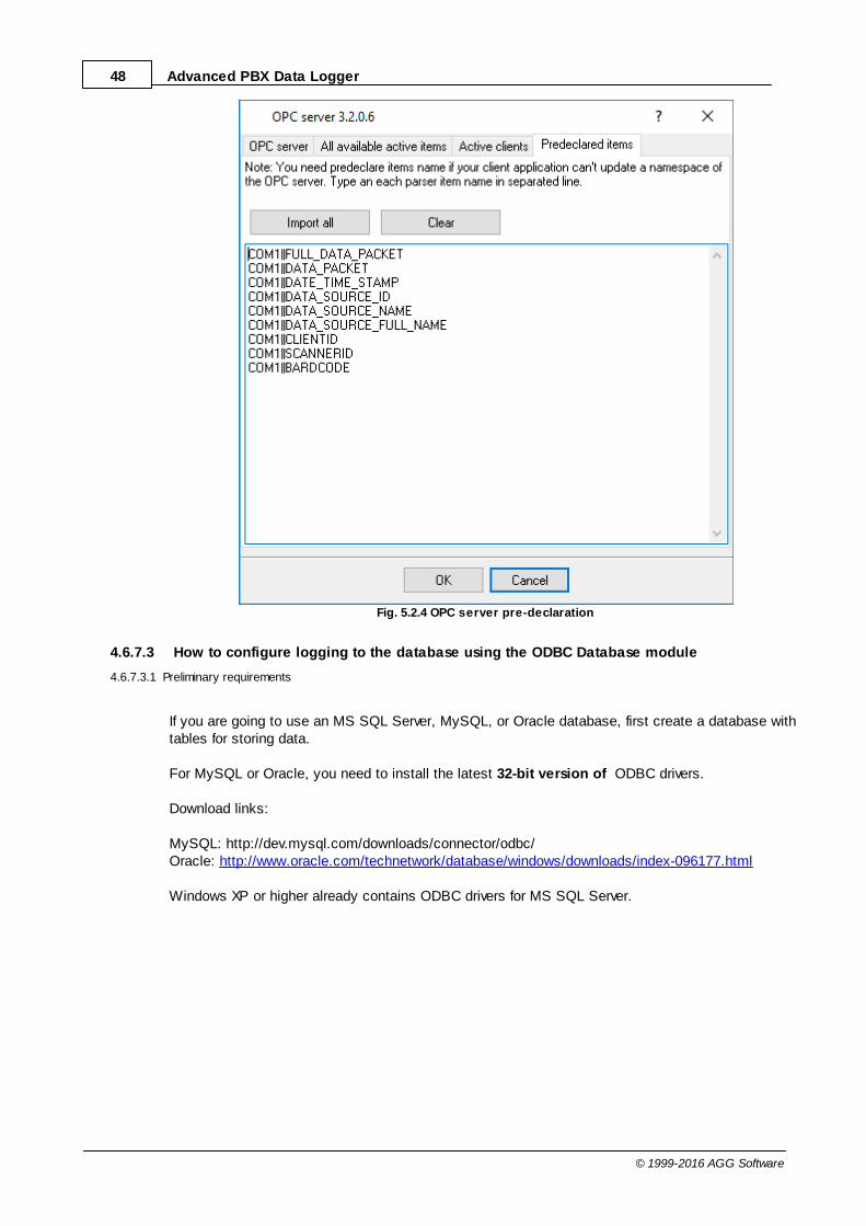
48 Advanced PBX Data Logger
© 1999-2016 AGG Software
Fig. 5.2.4 OPC server pre-declaration
4.6.7.3 How to configure logging to the database using the ODBC Database module
4.6.7.3.1 Preliminary requirements
If you are going to use an MS SQL Server, MySQL, or Oracle database, first create a database withtables for storing data.
For MySQL or Oracle, you need to install the latest 32-bit version of ODBC drivers.
Download links:
MySQL: http://dev.mysql.com/downloads/connector/odbc/Oracle: http://www.oracle.com/technetwork/database/windows/downloads/index-096177.html
Windows XP or higher already contains ODBC drivers for MS SQL Server.
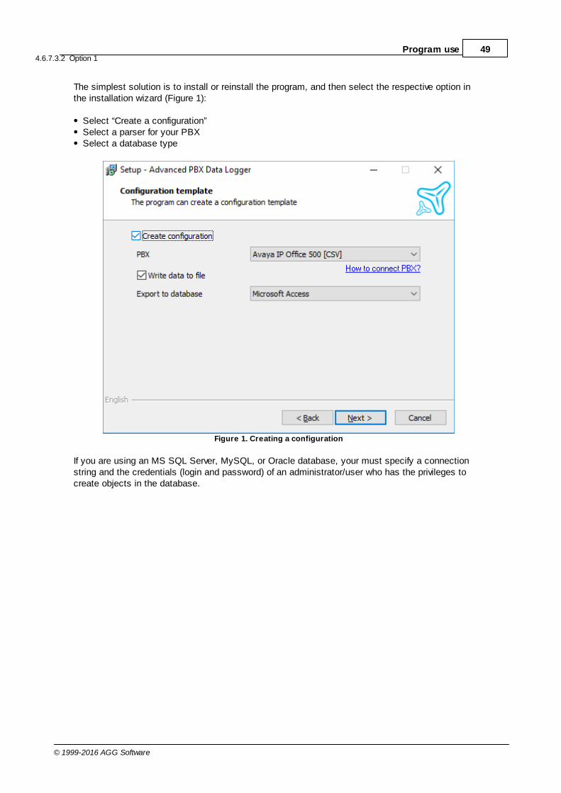
49Program use
© 1999-2016 AGG Software
4.6.7.3.2 Option 1
The simplest solution is to install or reinstall the program, and then select the respective option inthe installation wizard (Figure 1):
Select “Create a configuration”Select a parser for your PBXSelect a database type
Figure 1. Creating a configuration
If you are using an MS SQL Server, MySQL, or Oracle database, your must specify a connectionstring and the credentials (login and password) of an administrator/user who has the privileges tocreate objects in the database.
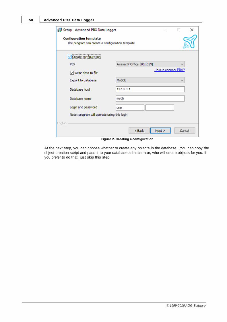
50 Advanced PBX Data Logger
© 1999-2016 AGG Software
Figure 2. Creating a configuration
At the next step, you can choose whether to create any objects in the database.. You can copy theobject creation script and pass it to your database administrator, who will create objects for you. Ifyou prefer to do that, just skip this step.
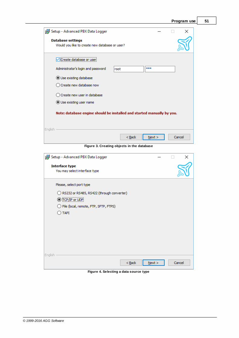
51Program use
© 1999-2016 AGG Software
Figure 3. Creating objects in the database
Figure 4. Selecting a data source type
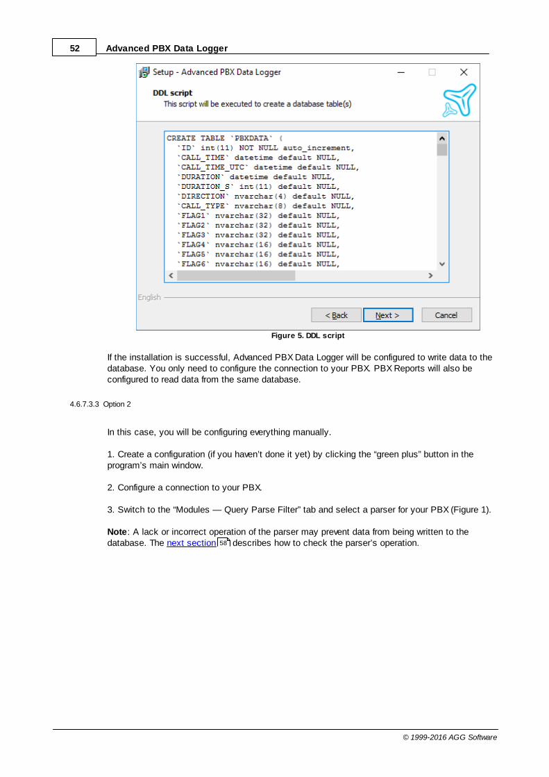
52 Advanced PBX Data Logger
© 1999-2016 AGG Software
Figure 5. DDL script
If the installation is successful, Advanced PBX Data Logger will be configured to write data to thedatabase. You only need to configure the connection to your PBX. PBX Reports will also beconfigured to read data from the same database.
4.6.7.3.3 Option 2
In this case, you will be configuring everything manually.
1. Create a configuration (if you haven’t done it yet) by clicking the “green plus” button in theprogram’s main window.
2. Configure a connection to your PBX.
3. Switch to the “Modules — Query Parse Filter” tab and select a parser for your PBX (Figure 1).
Note: A lack or incorrect operation of the parser may prevent data from being written to thedatabase. The next section describes how to check the parser’s operation.58
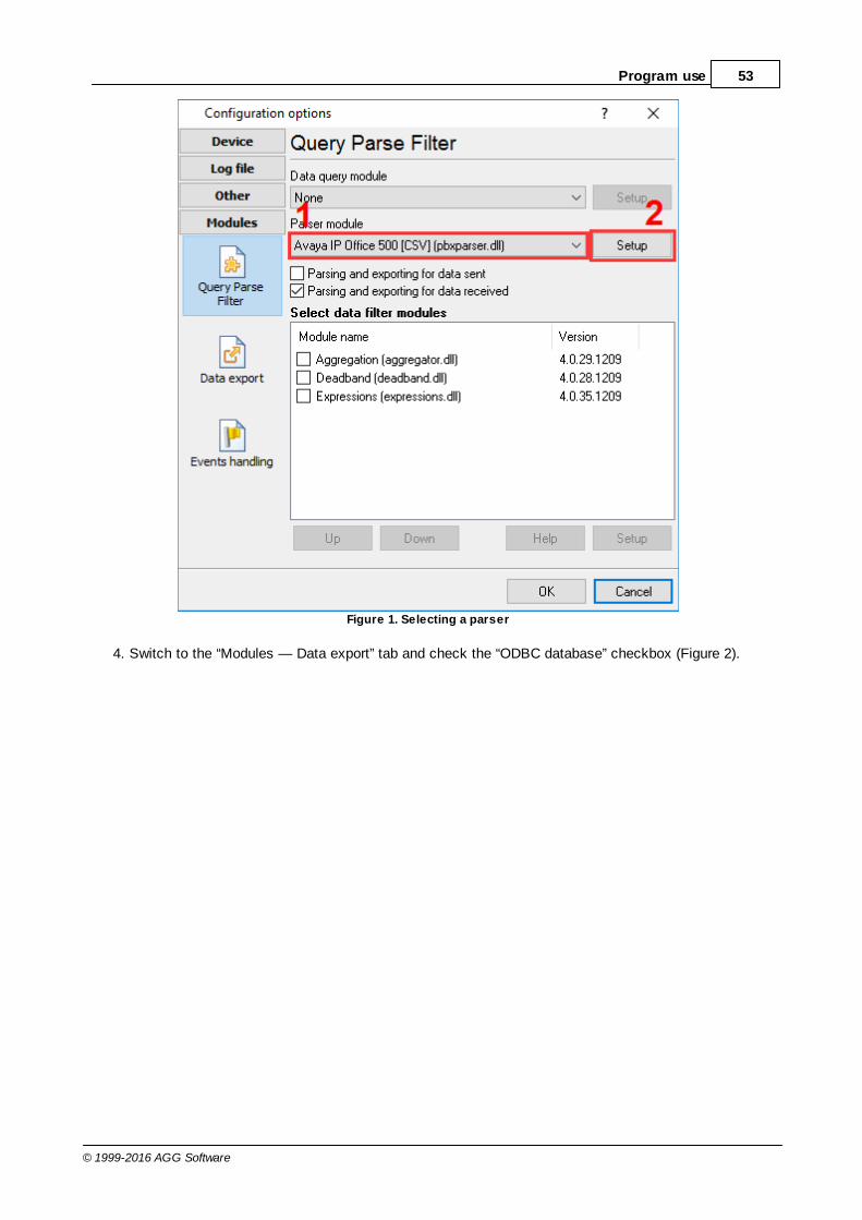
53Program use
© 1999-2016 AGG Software
Figure 1. Selecting a parser
4. Switch to the “Modules — Data export” tab and check the “ODBC database” checkbox (Figure 2).

54 Advanced PBX Data Logger
© 1999-2016 AGG Software
Figure 2. Selecting a data export module
5. Open the data export module’s settings by double-clicking the module’s name.
6. Click the “Load & Save” button (Figure 3), and select:
“PBX-Logger-ODBC-Items” — if you are going to write data to a MySQL, MS SQL Server, orOracle database.“PBX-Logger-ODBC-Access” — if you are going to write data to an MS Access database.
7. Switch to the “Common” tab (Figure 3) and enable data logging to the database.
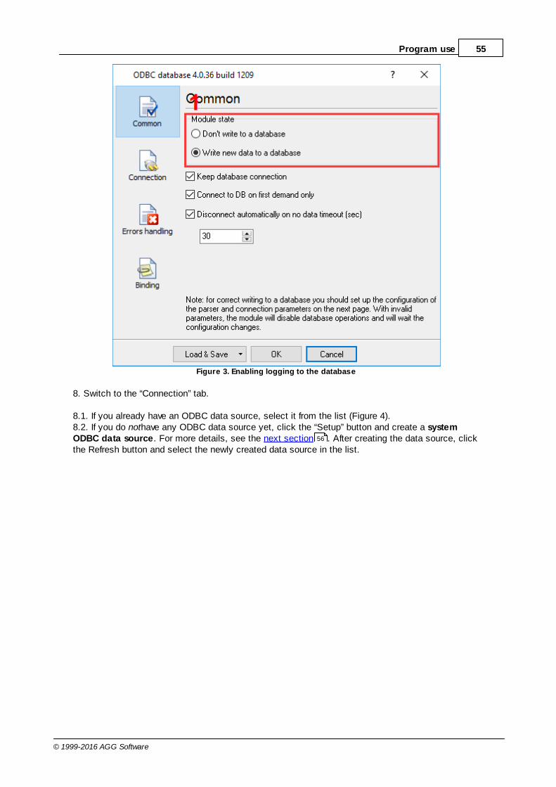
55Program use
© 1999-2016 AGG Software
Figure 3. Enabling logging to the database
8. Switch to the “Connection” tab.
8.1. If you already have an ODBC data source, select it from the list (Figure 4).8.2. If you do nothave any ODBC data source yet, click the “Setup” button and create a systemODBC data source. For more details, see the next section . After creating the data source, clickthe Refresh button and select the newly created data source in the list.
56

56 Advanced PBX Data Logger
© 1999-2016 AGG Software
Figure 4. Selecting an ODBC data source
9. Click “OK” and save all changes both in the ODBC database settings window and in the moduleselection window.
Now each time new data are received, the program will write them to the database.
4.6.7.4 Creating an ODBC data source
Note: In 64-bit editions of Windows, there are separate lists of data sources for the 32-bit and 64-bitmodes. You need to configure a data source for the 32-bit mode. To access the respective version ofODBC data source administrator, click the “Setup” button in the “ODBC database” module.
Note: The system ODBC data source lets you run the program as an application or as a service.
1. Switch to the “System DSN” tab and click the “Add” button (Figure 1).

57Program use
© 1999-2016 AGG Software
Figure 1. Data source administrator
2. In the window that opens, select a driver for your database (Figure 2).
Figure 2. Selecting a driver

58 Advanced PBX Data Logger
© 1999-2016 AGG Software
3. The following steps depend on the driver selected. Usually you should configure a connection tothe database.
4.6.7.5 Checking the parser’s operation
If you can see the data in the program’s main window but not in the database, you may need tocheck the parser. Possibly, the parser works incorrectly. That usually happens if the parser expectsdata in a different format than that sent by the PBX.
1. Select the “DDE server” data export module (Figure 1).
Figure 1. Selecting a data export module
2. Click “OK” to save changes.
3. Wait for new data.
4. Open the list of data export modules (Figure 1) and double-click “DDE server.”
5. In the module’s settings window, switch to the “All active items” tab. If you can see the parseddata from your PBX and everything looks fine, the parser works correctly.
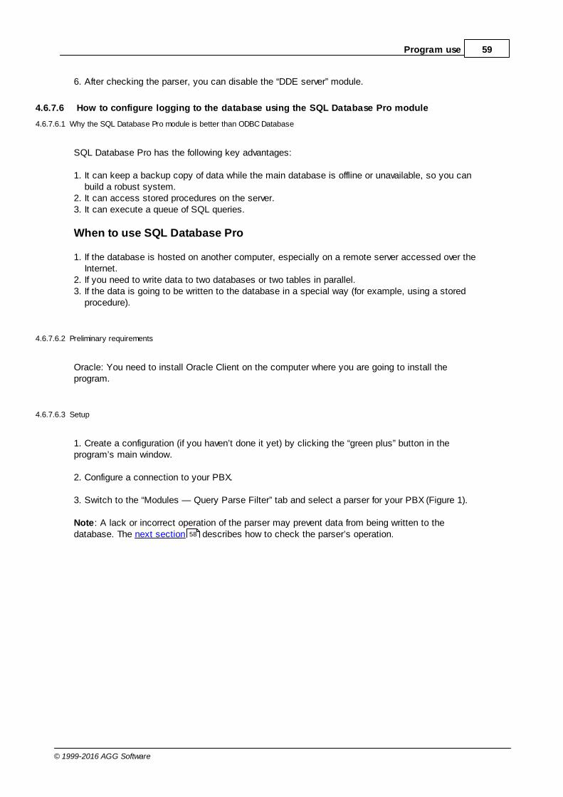
59Program use
© 1999-2016 AGG Software
6. After checking the parser, you can disable the “DDE server” module.
4.6.7.6 How to configure logging to the database using the SQL Database Pro module
4.6.7.6.1 Why the SQL Database Pro module is better than ODBC Database
SQL Database Pro has the following key advantages:
1. It can keep a backup copy of data while the main database is offline or unavailable, so you canbuild a robust system.
2. It can access stored procedures on the server.3. It can execute a queue of SQL queries.
When to use SQL Database Pro
1. If the database is hosted on another computer, especially on a remote server accessed over theInternet.
2. If you need to write data to two databases or two tables in parallel.3. If the data is going to be written to the database in a special way (for example, using a stored
procedure).
4.6.7.6.2 Preliminary requirements
Oracle: You need to install Oracle Client on the computer where you are going to install theprogram.
4.6.7.6.3 Setup
1. Create a configuration (if you haven’t done it yet) by clicking the “green plus” button in theprogram’s main window.
2. Configure a connection to your PBX.
3. Switch to the “Modules — Query Parse Filter” tab and select a parser for your PBX (Figure 1).
Note: A lack or incorrect operation of the parser may prevent data from being written to thedatabase. The next section describes how to check the parser’s operation.58
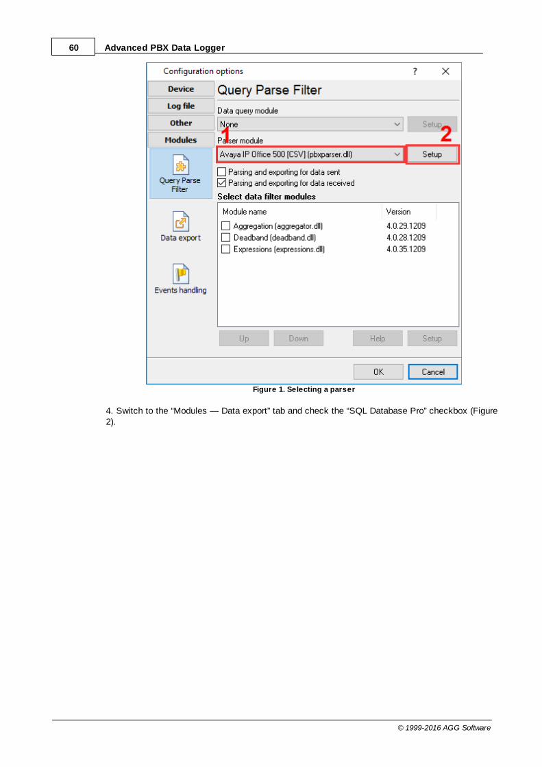
60 Advanced PBX Data Logger
© 1999-2016 AGG Software
Figure 1. Selecting a parser
4. Switch to the “Modules — Data export” tab and check the “SQL Database Pro” checkbox (Figure2).

61Program use
© 1999-2016 AGG Software
Figure 2. Data export module
5. Open the data export module’s settings by double-clicking the module’s name.
6. Switch to the “Connection mode” tab and make sure that the “Temporarily disable” checkbox isunchecked (Figure 3).
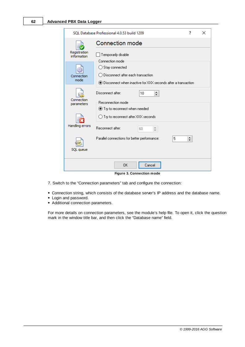
62 Advanced PBX Data Logger
© 1999-2016 AGG Software
Figure 3. Connection mode
7. Switch to the “Connection parameters” tab and configure the connection:
Connection string, which consists of the database server’s IP address and the database name.Login and password.Additional connection parameters.
For more details on connection parameters, see the module’s help file. To open it, click the questionmark in the window title bar, and then click the “Database name” field.

63Program use
© 1999-2016 AGG Software
Figure 4. Connection parameters
8. Switch to the “SQL queue” tab (Figure 5).
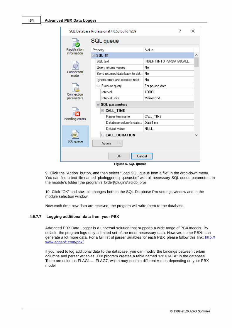
64 Advanced PBX Data Logger
© 1999-2016 AGG Software
Figure 5. SQL queue
9. Click the “Action” button, and then select “Load SQL queue from a file” in the drop-down menu.You can find a text file named “pbxlogger-sql-queue.txt” with all necessary SQL queue parameters inthe module’s folder [the program’s folder]\plugins\sqldb_pro\
10. Click “OK” and save all changes both in the SQL Database Pro settings window and in themodule selection window.
Now each time new data are received, the program will write them to the database.
4.6.7.7 Logging additional data from your PBX
Advanced PBX Data Logger is a universal solution that supports a wide range of PBX models. Bydefault, the program logs only a limited set of the most necessary data. However, some PBXs cangenerate a lot more data. For a full list of parser variables for each PBX, please follow this link: http://www.aggsoft.com/pbx/.
If you need to log additional data to the database, you can modify the bindings between certaincolumns and parser variables. Our program creates a table named “PBXDATA” in the database.There are columns FLAG1 ... FLAG7, which may contain different values depending on your PBXmodel.

65Program use
© 1999-2016 AGG Software
In the example below, you can see how to log the additional value “CALL_ID” for Avaya IP Office 500.
ODBC Database
1. Open the module’s settings window and switch to the “Binding” tab.
2. Find the column named “FLAG1” in the binding tree.
3. Click the “Parser item name” item and bind it to a different parser variable, “CALL_ID” (Figure 1). Ifthe drop-down list does not contain the variable name, enter that name manually.
Figure 1. Binding in ODBC Database
SQL Database Pro
You can configure SQL Database Pro in the same way.
1. Open the module’s settings window and switch to the “SQL queue” tab.
2. Find the column named “FLAG1” in the binding tree.
3. Click the “Parser item name” value and bind it to a different parser variable, “CALL_ID” (Figure 2). Ifthe drop-down list does not contain the variable name, enter that name manually.

66 Advanced PBX Data Logger
© 1999-2016 AGG Software
Figure 2. Binding in SQL Database Pro
Note: If the parser does not have the variable you specified, an empty value will be written to thecolumn.
4.6.7.8 Possible problems when the program running as a service tries to write data to the database
In Windows Vista or higher, logging to the database works fine if the program runs as an application,but fails if the program runs as a service.
Solution:
Such behavior is caused by the Windows security policy. A service is launched with theadministrator’s full privileges, but an application may be launched with the administrator’s limitedprivileges.
1. Run the program with the administrator’s full privileges by right-clicking the program’s icon andselecting “Run as administrator.”
2. Check the program’s settings. Possibly, they are different in this mode.
3. Make sure that the program writes data to the database.

67Program use
© 1999-2016 AGG Software
3.1 Database authentication may not allow a connection with such privileges.3.2 The firewall may block the connection to the database.
4. If everything looks fine but still no data are written to the database, do the following:
4.1. Enable logging of all messages to the program’s log file (Figure 1).4.2. Launch the service.4.3. Check the log file in the folder “C:\Users\All Users\Advanced PBX Data Logger\”
Figure 1. Configuring the program’s log file
4.6.7.9 How to view data in PBX Reports
PBX Reports uses the data written to the database by Advanced PBX Data Logger. PBX Reportscan work only with a MySQL, MS SQL Server, Oracle, or MS Access database. So Advanced PBXData Logger must be configured to write data to a database that is supported. If any data aresuccessfully written, they should appear on the “SMDR records” tab (Figure 1).

68 Advanced PBX Data Logger
© 1999-2016 AGG Software
Figure 1. PBX Reports w indow
Advanced PBX Data Logger writes data to the database in real time. To display new data on the“SMDR records” tab, click the Refresh button (see Figure 1).
What to do if I cannot see any data in PBX Reports?
Make sure that PBX Reports connects to the same database as used by Advanced PBX DataLogger. To do that, compare the database connection parameters in any data export module ofAdvanced PBX Data Logger (see the previous sections) and in the PBX Reports settings:
1. Select “Edit ? Options” in the main menu.2. Switch to the “Common — Database” tab.3. Check the connection parameters.
4.7 Program options
4.7.1 Window view
This tab in program options (fig. 6.1.1) allows you to customize appearance of the main window ofthe program (fig.1.1.1 ). You can access this tab through the "Options -> Program options" menuitem in the main window.
5

69Program use
© 1999-2016 AGG Software
Fig. 6.1.1 Window view setting
You can set following parameters:
Start in minimized state - at start Advanced PBX Data Logger will automatically put its iconon panel near clock (SysTray fig. 6.1.2);Minimize to SysTray - while the main window of Advanced PBX Data Logger minimizes, theprogram will automatically put its icon to the panel near clock;Show data window - if you specify this option, then the program will display all data in themain window. If you are logging many ports on slow PC, then you can computer CPU load ratewith disabling of this option;Output data on screen in minimized state - if you'll enable this option, then the program willdisplay processed data in minimized state. If you are logging many data sources on slow PC,then you can decrease computer central processor load rate with disabling of this option;Font type - the data will be displayed with this font type in the main window only. Werecommend to use mono-spaced fonts in this field, such as: Terminal, Courier etc.;Screen buffer - at exceeding of value specified the data window will be cleaned;Window view - will let you setup data window view (font color, font type, background color).Transparency - in Windows 2000 and later will let you set transparency of the main window.The most left position is normal window view and most right position is maximum transparency.Wrap words - if you didn't configure a parser module or your data flow doesn't contain a blocksseparator, then your data without this option enabled will be displayed as one long string in thedata window.

70 Advanced PBX Data Logger
© 1999-2016 AGG Software
Fig. 6.1.2 Systray - panel near clock
4.7.2 Date/time stamp view
This group of options (fig. 6.2.1) allows to configure the format of date/time stamps that will be usedin the main program window and log files.
Fig. 6.2.1 Configuring data/stamp view
Prefix/Postfix characters for display output - these options allow to define beginning and endingcharacters of a date/time stamp that will be showed in the program window. When outputting data to

71Program use
© 1999-2016 AGG Software
a log file the program uses individual characters for each configuration.
View mode - allows to select the standard or define the custom format of the date/time stamp.
Font - this group allows to define the color and font of date/time stamp.
Add data direction sign to a stamp - if this option is activated then the program will append TX orRX to the end of the stamp.
Add data source ID to a stamp - if this option is activated then the program will data append datasource ID at the beginning of the stamp. For example, COM1.
4.7.3 Protocol and errors handling
While the program execute, she generates many messages about errors and events. All thesemessages are being registered in a protocol file. This can be start or stop of the program, somemessages from plug-in modules etc. On this tab you can define the kind of messages, which youwant to put a protocol file (fig. 6.3.1). Here you can set maximum protocol file size and a formattingmode. Usually, the protocol file is in a program folder and has the name of the program with the 'log'extension.
34

72 Advanced PBX Data Logger
© 1999-2016 AGG Software
Fig. 6.3.1 Protocol settings
Advanced PBX Data Logger works with three types of messages:
Information messages - this type of messages informs you on operations which are fulfilled inthe current time;Warnings - warns you of possible failures or possible errors. Interference of the user is notrequired, but check is required;Errors - the program has detected an error which elimination needs involvement of the user.
There is the possibility to log following events:
Program messages - messages about start or stop of the program, etc.;Data query - messages which are generated in a data query module;Data parser - messages which are generated in a data parser module;Data export - messages which are generated in a data export module;Other - messages that can not be associated with types above.
You can write each type of messages to a protocol file or/and to the list in the main window. Please,specify necessary options for each message type at "Window" and "File" fields.
If you don't want to allow to grow a protocol file size to an unlimited size, then you can enable the"Clean protocol at program start" or limit protocol file size in the "Size" field.
Some exceptional messages can occur while the program execute. In most cases these messagescrash the program and the most safe way is to restart the program. Please, specify the "Restartprogram at exception" option and the program will be restarted automatically.
If you want look all program messages, then you can disable the "Don't display messages atunhandled exceptions" check box and the program will open the exception message window withdetailed information.
4.7.4 Service mode on Windows 2000+4.7.4.1 Configuration
Windows NT+ services use will let you:
control service on local and remote computers, including remote computers with Windows NT4.0 system;setup actions on emergency service restore in case of failure, for example auto service orcomputer restart (only on computers with Windows 2000 or later);create for services other names and descriptions, to find them easier (only on computers withsystem Windows 2000 or later); run service before user login (password input); service can be setup on automatic start after operation system load.
Note 1: you must be logged in as an administrator in order to change the configuration or control theservice in any way (start, stop, pause, continue).
Note 2: On Windows Vista and later you should start the program with elevated administrator

73Program use
© 1999-2016 AGG Software
privileges.
If you want to use the program as a service application, then, please, go to the "Options -> Programoptions -> Windows service" tab (fig. 6.4.1), then enable the "Use program as a service" check box.Later, please, specify the startup type of the service. There can be following variants:
Fig. 6.4.1 Service settings
1. Automatic - service will be started automatically at every Windows start, before user login;2. Manual - you can start the service application in the "Services" window in the Control panel (fig.
6.4.2);3. Disabled - service can't be started.
If you want to change program settings while service mode, then enable the "Allow service to interactwith desktop" option. In this case, the program will put the icon to the SysTray (fig. 6.4.2). But thenyour interactive service will be restarted while user log off.
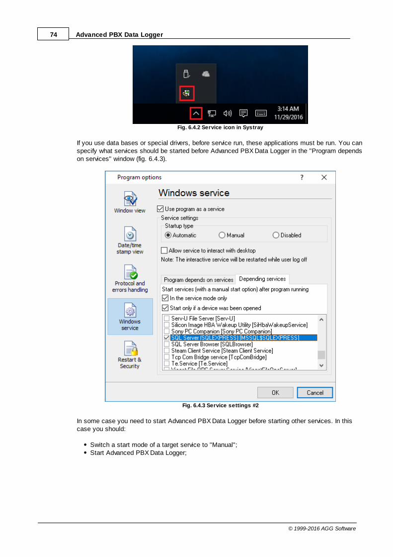
74 Advanced PBX Data Logger
© 1999-2016 AGG Software
Fig. 6.4.2 Service icon in Systray
If you use data bases or special drivers, before service run, these applications must be run. You canspecify what services should be started before Advanced PBX Data Logger in the "Program dependson services" window (fig. 6.4.3).
Fig. 6.4.3 Service settings #2
In some case you need to start Advanced PBX Data Logger before starting other services. In thiscase you should:
Switch a start mode of a target service to "Manual";Start Advanced PBX Data Logger;

75Program use
© 1999-2016 AGG Software
Set on the target service at the "Services depend on ASDL" tab;Select mode when you need start these service;Restart Advanced PBX Data Logger.
After you installed the service mode of the program, restart a computer or run the service manuallyfrom the "Services" window in the Control panel (fig. 6.4.4)
Fig. 6.4.4 Manual service run (in Windows 2000)
After start of the service, the service processes names will be displayed in a process list:pbxloggersrv.exe and pbxlogger.exe (fig. 6.4.5). The 'pbxloggersrv.exe' application makes interfacebetween the service manager and the Advanced PBX Data Logger software. Unlike srvany.exe utility,our service stops safely.
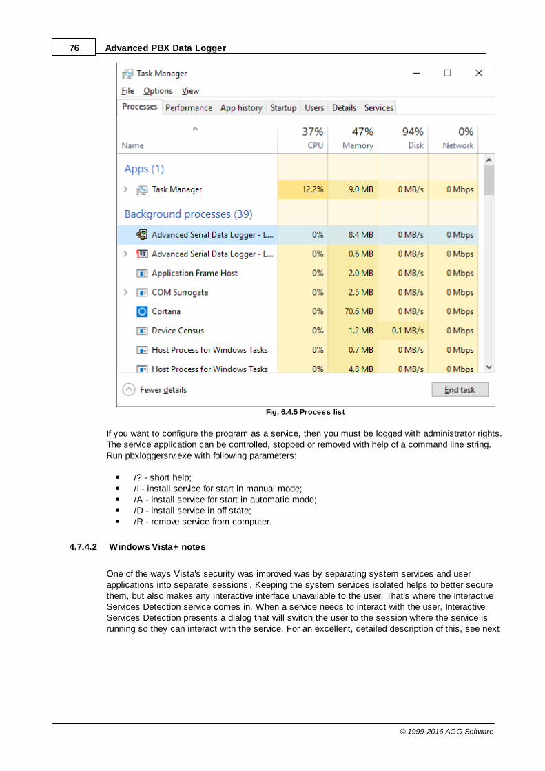
76 Advanced PBX Data Logger
© 1999-2016 AGG Software
Fig. 6.4.5 Process list
If you want to configure the program as a service, then you must be logged with administrator rights.The service application can be controlled, stopped or removed with help of a command line string.Run pbxloggersrv.exe with following parameters:
/? - short help;/I - install service for start in manual mode;/A - install service for start in automatic mode;/D - install service in off state;/R - remove service from computer.
4.7.4.2 Windows Vista+ notes
One of the ways Vista's security was improved was by separating system services and userapplications into separate 'sessions'. Keeping the system services isolated helps to better securethem, but also makes any interactive interface unavailable to the user. That's where the InteractiveServices Detection service comes in. When a service needs to interact with the user, InteractiveServices Detection presents a dialog that will switch the user to the session where the service isrunning so they can interact with the service. For an excellent, detailed description of this, see next

77Program use
© 1999-2016 AGG Software
paragraph.
Many sites recommend disabling this service, but doing so will result in you not being able tointeract with any services that require your attention. This service is run manually by default, sothere is little point to disabling it unless you don't want to be bothered by important information fromthe software you may be trying to run.
Display Name: Interactive Services DetectionService Name: UI0DetectProcess Name: UI0Detect.exeDescription: Enables user notification of user input for interactive services, which enables accessto dialogs created by interactive services when they appear. If this service is stopped, notificationsof new interactive service dialogs will no longer function and there may no longer be access tointeractive service dialogs. If this service is disabled, both notifications of and access to newinteractive service dialogs will no longer function.Path to Executable: %windir%\system32\UI0Detect.exeDefault Startup:
* Home Basic: Manual * Home Premium: Manual * Business: Manual * Enterprise: Manual * Ultimate: Manual
4.7.5 Restart & Security
Sometimes the program should be restarted. For example, if you've changed the program settingsremotely and want to reload program automatically with the new settings. To do that, specify thetime for restarting the program on the "Restart & Security" tab in program options "Options->Program options". Just specify the time of day, when the program should be being restarted.
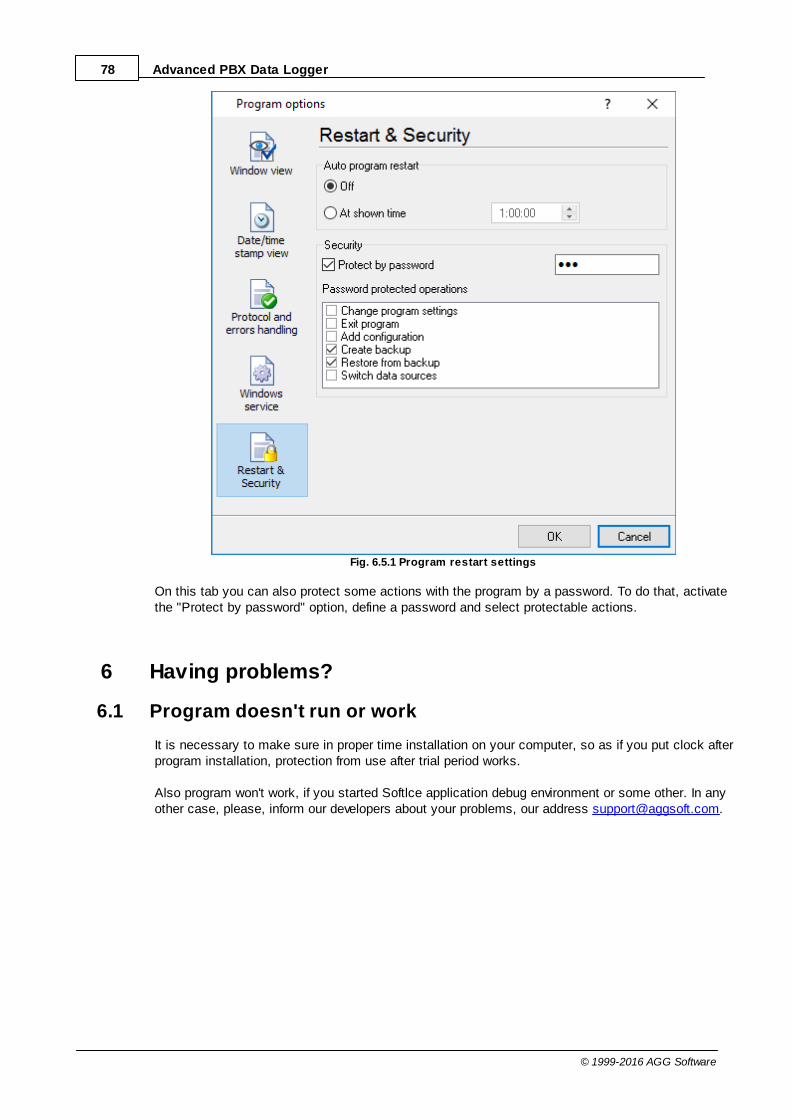
78 Advanced PBX Data Logger
© 1999-2016 AGG Software
Fig. 6.5.1 Program restart settings
On this tab you can also protect some actions with the program by a password. To do that, activatethe "Protect by password" option, define a password and select protectable actions.
6 Having problems?
6.1 Program doesn't run or work
It is necessary to make sure in proper time installation on your computer, so as if you put clock afterprogram installation, protection from use after trial period works.
Also program won't work, if you started Softlce application debug environment or some other. In anyother case, please, inform our developers about your problems, our address [email protected].
79Having problems?
© 1999-2016 AGG Software
6.2 FAQ
Question: Why COM port doesn't open?Answer: Probably, some other program already uses it (COM port). This can be DOS application,for example.
Question: What to do? Answer: Close application, using this communicative port (for DOS application close also DOSsession window). Or use other communicative port. Probably, at start or some program stop wasmade some fatal error and COM port wasn't properly closed.
Question: Is it possible to set variable data transmit rate or transmit 9 data bits?Answer: No, Windows operation system doesn't let such liberties.
Question: What cutoff point type to use: DB25 or DB 9?Answer: It makes no difference, select only in program corresponding COM-port. USUALLY DB25 -COM2, DB9 - COM1
Question: Is cable connection direct or null-modem?Answer: Everything depends on your device cutoff point. Usually it is necessary to use null-modemcable, in which signals are moved apart in this way:
Device | Computer_____________RXD <--> TXDTXD <--> RXDGND <--> GND
if device uses special signals DTR and others and you don't want to use hardware data transmitcontrol, at device side connect 7 and 8 contacts of DB9 cutoff point or analogous DB25 cutoff pointsignals.
More hardware tips and articles you can found on our site http://www.aggsoft.com.
Question: Is data receive becomes at once after program start or data receive must be started? Answer: Everything depends on your device type, usually in device settings is selected to echo viewdata to COM port. If your device doesn't support this mode, write what initialization string must besent to read out data, and we add this possibility to the program.