advanced simulator for combat, transport meeting proceedings/rto... · advanced simulator for...
TRANSCRIPT
RTO-MP-AVT-110 12 - 1
UNCLASSIFIED/UNLIMITED
UNCLASSIFIED/UNLIMITED
Advanced Simulator for Combat, Transport Vehicles, Submarines, Vessels, Airplanes and Helicopters
Jörg Gschwilm DLR - German Aerospace Center
Institute of Robotics and Mechatronics P.O. Box 1116 82230 Weßling
Germany
ABSTRACT
Virtual product development with the aid of simulation software is particularly advanced in the vehicle industry. The purely visual representation of simulation results within a graphic environment often makes it difficult to sufficiently record all necessary evaluation criteria. Such limitations are largely reduced with the aid of a simulator which enables the evaluation of vehicle dynamics as well as vibration comfort. The application fields of such a simulator range from a projection of vibrations to an interactive simulation of vehicle dynamics.
The motion system plays an important role in simulator experiments. It represents a compromise between technical requirements (or wishes), current technical feasibility and financial possibilities.
The technical requirements on the motion system of a universal simulator for road and rail vehicles as well as aircraft cover a wide spectrum of potential applications. With the aid of the simulation, measurement results from experiments as well as experience, the limiting parameters of this simulator are assessable for certain manoeuvres.
1.0 INTRODUCTION
Computer-aided simulation for the design and evaluation of dynamic systems has reached a high development status in the vehicle industry. It makes an important contribution towards the process of virtual product development. However, the purely visual evaluation of simulation results by means of animations and/or graphic analyses within a virtual reality environment is in many cases not sufficient to give a complete impression of the specific behaviour of a vehicle. The subjective component of the evaluation by the passenger and/or driver is missing. In particular vibrations and forces that affect the occupants such as inertia forces, provoked by braking, curving, interaction forces from control elements as well as acoustic and climatic influences, can only be inadequately evaluated on the basis of results from the computer-aided simulation. Furthermore, the number of cost-intensive hardware prototypes is to be reduced to decrease time-to-market. As a result of this there are less and less possibilities of subjectively checking the special features of a vehicle, such as driving dynamics during certain manoeuvres and driving comfort, before the production can be started. Consequently, revolutionary decisions with the aid of virtual prototypes have to be made. The danger then arises that wrong decisions are made as a result of inadequate vehicle evaluations.
With the aid of a simulator that can realistically transmit both the driving dynamics and the vibration comfort of a vehicle, the above mentioned limitations can to a large extent be eliminated.
Paper presented at the RTO AVT Symposium on “Habitability of Combat and Transport Vehicles: Noise, Vibration andMotion”, held in Prague, Czech Republic, 4-7 October 2004, and published in RTO-MP-AVT-110.

Advanced Simulator for Combat, Transport Vehicles, Submarines, Vessels, Airplanes and Helicopters
12 - 2 RTO-MP-AVT-110
UNCLASSIFIED/UNLIMITED
UNCLASSIFIED/UNLIMITED
The application areas of such a simulator range from the implementation of vibrations to the interactive simulation of driving dynamics as far as the research platform for investigations on ergonomic and medical questions at the human-vehicle interface. Among other things new, advanced comfort parameters on extensive test series can also be compiled which then include information on rotation motions, e.g. important for tilting trains. In addition an interactive real-time simulation will enable the driving dynamics of a vehicle concept to be evaluated, whereby not only will the passive behaviour be displayed but also active components can be examined.
The automobile industry and various research institutes operate diverse driving simulators depending on the requirements and state of development. The main applications determine the construction and development stages of the simulators. The most important applications are:
• driver assistance systems
• vehicle development
• driver behaviour
• system development
• driving dynamics
• traffic research
• medical research
• comfort studies
2.0 EVALUATION OF VIRTUAL PROTOTYPES
Ride impressions must be conveyed for the so-called offline operation (passive) and online operation (interactive). A Dynamic Driving and Comfort Simulator (DDCS) must give the driver and/or passenger the following ride impressions:
• dynamic driving and comfort vibrations in all six degrees of freedom
• visual impressions
• acoustic impressions
• temperature sensation
Such a DDCS can be designed as a modular system and besides the required computer infrastructure consists of the following sub-systems:
• motion system with control
• software for vehicle models with transformation of motion
• vehicle interior
• visualisation
• acoustic system
• dome-climate simulation
The drafted system of a DDCS has a multitude of application possibilities. Subject to accordance with the goals, these apply to vehicles of all kinds, i.e. to all road and rail vehicles, but also to aircraft, monorails or

Advanced Simulator for Combat, Transport Vehicles, Submarines, Vessels, Airplanes and Helicopters
RTO-MP-AVT-110 12 - 3
UNCLASSIFIED/UNLIMITED
UNCLASSIFIED/UNLIMITED
helicopters. Simulators for the outlined field of application can be based on different solutions. Depending on the specification of the priority, motion platforms with low- or high-frequency actuators are possible. The motion area can also be organized differently and the kinematic basic concepts chosen accordingly.
In the past two basically different approaches became accepted:
Dynamic Driving Simulators: Simulators for reproducing the vehicle dynamic behaviour are based on a Hexapod-Platform (Stewart-Platform). The motions are mostly low-frequency but can also cover a larger amplitude area. In some cases these platforms are additionally coupled with linearly manoeuvrable test sleds in order to improve the acceleration mock-up.
Comfort Simulators: As a rule measured acceleration spectra are converted into motions with the aid of high-frequency actuators. The path amplitudes can be kept relatively small, whereby in comparison to dynamic simulators kinematic versions other than the Stewart-platform are also applied.
For an integrated investigation of the overall behaviour of virtual vehicles the entire frequency and amplitude area must be considered. And for the specification of new comfort guidelines the interaction of low- and high-frequency accelerations as well as the correlated visual impressions must also be taken into account.
Furthermore there is the need to apply the comfort simulation to virtual vehicles because in future fewer hardware prototypes will be used (saving of costs, time-to-market). This means that comfort simulation and dynamic driving simulation can be combined. Preliminary experiments on prototypes could then be greatly reduced. In addition, such an online simulation with the DDCS has the advantage that the interface between virtual design and reality can be presented extremely flexibly. For example, a seat suspension can be displayed in the computer together with the whole vehicle and only the seat shell is mounted on the motion platform.
3.0 DEMANDS ON A DYNAMIC DRIVING AND COMFORT SIMULATOR
In this section the demands on a simulator will be defined by means of diverse simulation experiments.
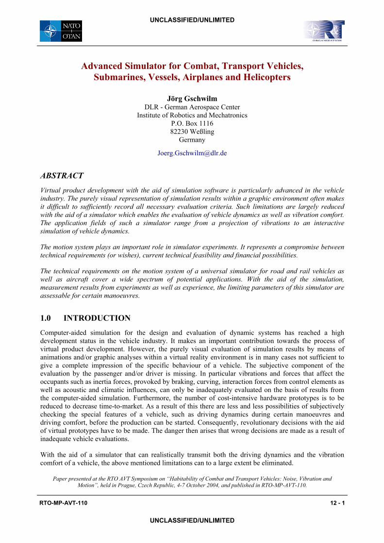
3.1 Road vehicles - lane change test In order to evaluate the driving dynamics and also the driving safety of road vehicles, different so-called 'close-loop-tests’ exist, e.g. ISO-lane change, ‘Elk Test’, 10x36 m- and 10x18 m-Slalom. These tests are strongly marked by the driver's influence. They lie outside the normal driving conditions and present border situations which give important information for the evaluation of the vehicle. These manoeuvres yield high lateral accelerations but relatively small longitudinal accelerations. Demands on braking manoeuvres have been discussed e.g. in [1].
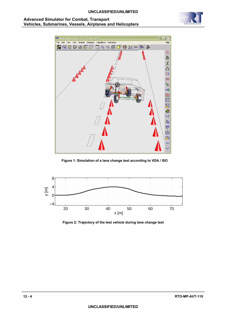
As an example of a critical vehicle dynamic manoeuvre the lane change test according to VDA, which was also accepted into the International Norm ISO 3888-2, was simulated with the multibody simulation software SIMPACK [2]. Figure 1 shows the test scenario, the initial speed for this computer-aided simulation was 60 km/h. The important results for the simulator are shown in Figures 2 and 3.
Advanced Simulator for Combat, Transport Vehicles, Submarines, Vessels, Airplanes and Helicopters
12 - 4 RTO-MP-AVT-110
UNCLASSIFIED/UNLIMITED
UNCLASSIFIED/UNLIMITED
Figure 1: Simulation of a lane change test according to VDA / ISO
20 30 40 50 60 70−4
0
4
8
x [m]
y [m
]
Figure 2: Trajectory of the test vehicle during lane change test

Advanced Simulator for Combat, Transport Vehicles, Submarines, Vessels, Airplanes and Helicopters
RTO-MP-AVT-110 12 - 5
UNCLASSIFIED/UNLIMITED
UNCLASSIFIED/UNLIMITED
−10
0
10a x [m
/s2 ]
−10
0
10
a y [m/s
2 ]
0 1 2 3 4 5 60
10
20
t [s]
a z [m/s
2 ]
Figure 3: Accelerations at the driver seat during lane change test
3.2 Rail Vehicles In order to outline the demands made by rail vehicles on the simulator, two typical manoeuvres have been chosen for the simulation. Contrary to the road vehicles, the subjective influence by a driver is not considered for these simulation results. It must however be taken into account that the driver determines the longitudinal acceleration of the vehicle for track-guided vehicles as well. The goal of these simulation scenarios is the offline simulation, in order to examine different influences on the riding comfort of rail vehicles.
In the simulated switch crossing [3] the passenger car crosses a switch with a radius of 500m at a speed of 100 km/h. The accelerations in all three directions are shown in Figure 4. The values remain relatively small.
Advanced Simulator for Combat, Transport Vehicles, Submarines, Vessels, Airplanes and Helicopters
12 - 6 RTO-MP-AVT-110
UNCLASSIFIED/UNLIMITED
UNCLASSIFIED/UNLIMITED
−2
−1
0
1
2a x [m
/s2 ]
−1
0
1
2
3
a y [m/s
2 ]
0 0.5 1 1.5 2 2.5 3 3.5 4−12
−11
−10
−9
−8
t [s]
a z [m/s
2 ]
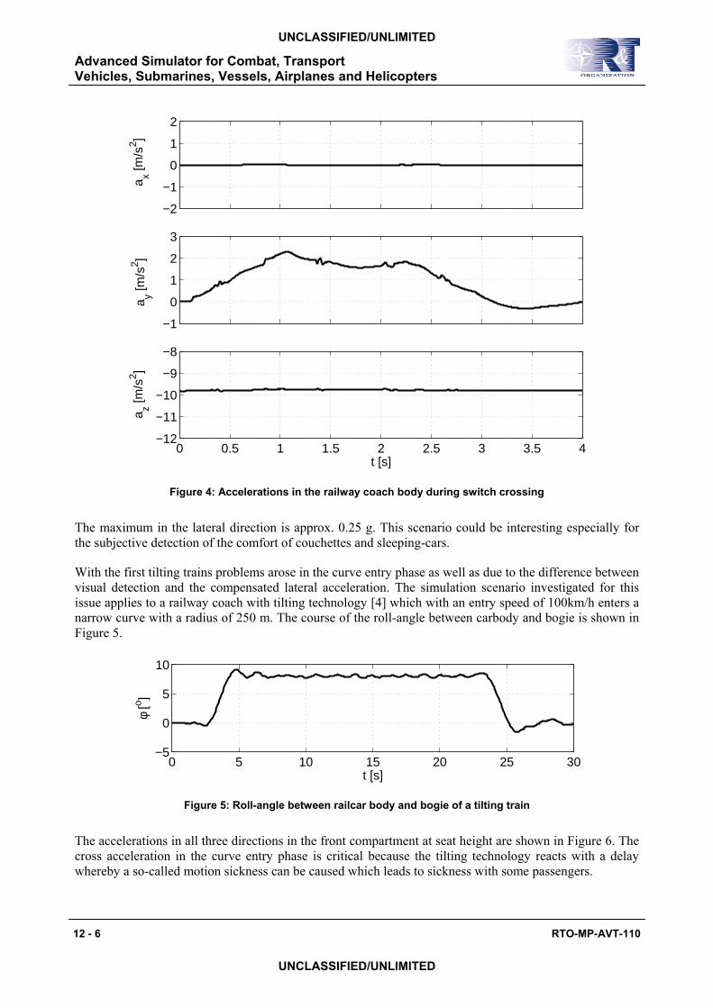
Figure 4: Accelerations in the railway coach body during switch crossing
The maximum in the lateral direction is approx. 0.25 g. This scenario could be interesting especially for the subjective detection of the comfort of couchettes and sleeping-cars.
With the first tilting trains problems arose in the curve entry phase as well as due to the difference between visual detection and the compensated lateral acceleration. The simulation scenario investigated for this issue applies to a railway coach with tilting technology [4] which with an entry speed of 100km/h enters a narrow curve with a radius of 250 m. The course of the roll-angle between carbody and bogie is shown in Figure 5.
0 5 10 15 20 25 30−5
0
5
10
φ [o ]
t [s]
Figure 5: Roll-angle between railcar body and bogie of a tilting train
The accelerations in all three directions in the front compartment at seat height are shown in Figure 6. The cross acceleration in the curve entry phase is critical because the tilting technology reacts with a delay whereby a so-called motion sickness can be caused which leads to sickness with some passengers.

Advanced Simulator for Combat, Transport Vehicles, Submarines, Vessels, Airplanes and Helicopters
RTO-MP-AVT-110 12 - 7
UNCLASSIFIED/UNLIMITED
UNCLASSIFIED/UNLIMITED
−1
0
1a x [m
/s2 ]
−1
0
1
2
a y [m/s
2 ]
0 5 10 15 20 25 30
−11
−10
−9
a z [m/s
2 ]
t [s]
Figure 6: Accelerations in the carbody of a tilting train
3.3 Aircraft The landing in San Francisco has been chosen as an example from the field of aviation [5]. Figure 7 shows the vertical acceleration in the cabin of the landing aircraft. In this case the vertical acceleration is shown without the ground acceleration g. The maximum values of the acceleration are approx. 0.9 g. The vibrations shown are mainly influenced by pitch motions of the fuselage.
-10
-5
0
5
10
0 2 4 6 8 10
a[m
/s]
z
2
t [s]
Figure 7: Vertical acceleration in the aircraft cabin during braking, [5]

Advanced Simulator for Combat, Transport Vehicles, Submarines, Vessels, Airplanes and Helicopters
12 - 8 RTO-
UNCLASSIFIED/UNLIMITED
UNCLASSIFIED/UNLIMITED
4.0 LIMITS OF A REALISTIC SIMULATION
The simplest driving simulator is one with a fixed base, complemented with a visualisation and acoustics system. Even with this relatively plain structure, investigations in driving behaviour are possible.
However, the trend in simulator design is clearly going in the direction of a simulation closed to the reality. But this requires the application of a motion system with six degrees of freedom, a complex 360° visualisation system and a multi-channel acoustics system. Two additional space axes, in which the whole system can move two-dimensionally at base level, form another extension step. In order to test higher-frequency aspects of comfort, motions with frequencies up to approx. 40 Hz must be superimposed on the simulator platform. The limited motions of each simulator system can be compensated by the so-called ‘Wash-out’ principle. After a realistic initial acceleration of the motion platform by tilting the platform, scaling the motions, by visualisation and acoustics, the impression of the process of acceleration is suggested by weight forces [9]. Meanwhile the motion platform moves with an acceleration below the perception by the passenger into the next necessary position. Figure 8 shows the procedure in principle.
Figure 8: Wash-out phases, [7]
4.1 Theoretical limits of hexapod motion systems For the movement of a platform in all six degrees of freedom the so-called Hexapod configurlinear actuators (Figure 9) is often chosen because of the comparatively simple constructionprinciple.
e
t
v e
m
iacce
ready facce
wash-out and rese perce
tim
displacemen
real ehiclmotion platfor
1
nitial leration
3
or the next leration
2
t below the limit ofption
MP-AVT-110
ation of six and active
Advanced Simulator for Combat, Transport Vehicles, Submarines, Vessels, Airplanes and Helicopters
RTO-MP-AVT-110 12 - 9
UNCLASSIFIED/UNLIMITED
UNCLASSIFIED/UNLIMITED
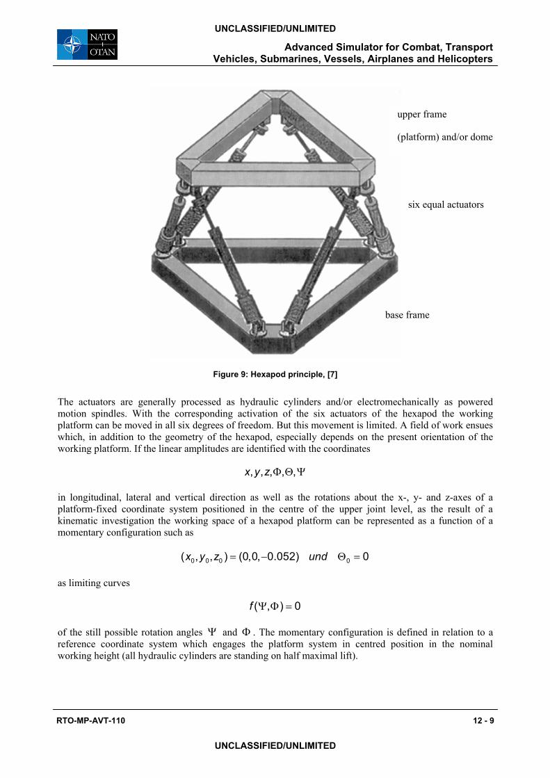
Figure 9: Hexapod principle, [7]
The actuators are generally processed as hydraulic cylinders and/or electromechanically as powered motion spindles. With the corresponding activation of the six actuators of the hexapod the working platform can be moved in all six degrees of freedom. But this movement is limited. A field of work ensues which, in addition to the geometry of the hexapod, especially depends on the present orientation of the working platform. If the linear amplitudes are identified with the coordinates
Φ Θ Ψ, , , , ,x y z
in longitudinal, lateral and vertical direction as well as the rotations about the x-, y- and z-axes of a platform-fixed coordinate system positioned in the centre of the upper joint level, as the result of a kinematic investigation the working space of a hexapod platform can be represented as a function of a momentary configuration such as
= − Θ =0 0 0 0( , , ) (0,0, 0.052) 0x y z und
as limiting curves
Ψ Φ =( , ) 0f
of the still possible rotation angles Ψ and Φ . The momentary configuration is defined in relation to a reference coordinate system which engages the platform system in centred position in the nominal working height (all hydraulic cylinders are standing on half maximal lift).
upper frame
(platform) and/or dome
base frame
six equal actuators

Figure 10 shows such a limiting curve for a hexapod with hydraulic cylinders and the following characteristic dimensions:
triangular length of the base 3,800 m
triangular length of the platform 1,900 m
half joint distance 0,065 m
maximum piston stroke 0,800 m
fitting length of the hydraulic cylinder 2,368 m
nominal working height 2,100 m
If the configuration shifted in the y-direction by y etc = ±0 0.02y m is considered instead of the assumed centred momentary position of the platform in Figure 10, the result is the working space shown in Figure 11.
-40
-30
-20
-10
0
10
20
30
40
-40 -30 -20 -10 0 10 20 30 40� [grad]
{ X0 Y0 Z0 } = { 0.00 0.00 -0.052 }
�[g
rad
]
Figure 10: Working space of the mentioned hexapod, described by a limiting curve which represents the still possible rotations about z and x-axes, [6] Ψ Φ =( , ) 0f
12 - 10 RTO-MP-AVT-110
Ψ
Ф
Advanced Simulator for Combat, Transport Vehicles, Submarines, Vessels, Airplanes and Helicopters
UNCLASSIFIED/UNLIMITED
UNCLASSIFIED/UNLIMITED
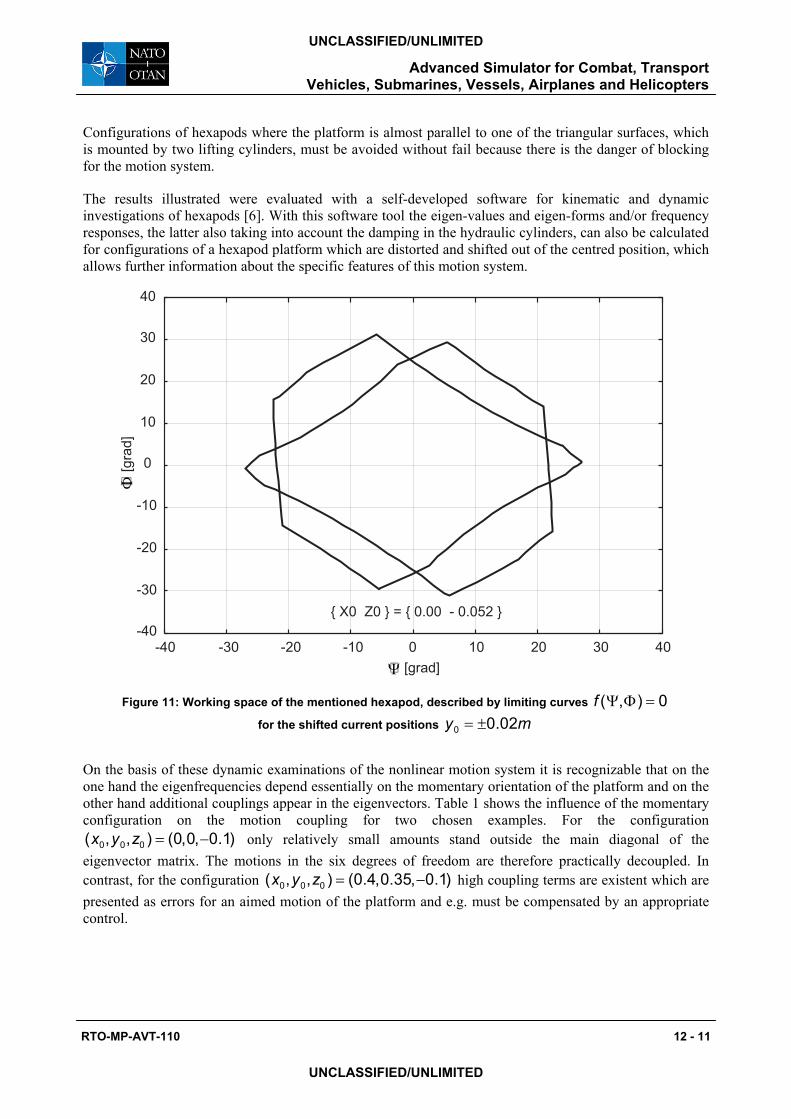
Configurations of hexapods where the platform is almost parallel to one of the triangular surfaces, which is mounted by two lifting cylinders, must be avoided without fail because there is the danger of blocking for the motion system.
The results illustrated were evaluated with a self-developed software for kinematic and dynamic investigations of hexapods [6]. With this software tool the eigen-values and eigen-forms and/or frequency responses, the latter also taking into account the damping in the hydraulic cylinders, can also be calculated for configurations of a hexapod platform which are distorted and shifted out of the centred position, which allows further information about the specific features of this motion system.
-40
-30
-20
-10
0
10
20
30
40
-40 -30 -20 -10 0 10 20 30 40
{ X0 Z0 } = { 0.00 - 0.052 }
� [grad]
�[g
rad]
Figure 11: Working space of the mentioned hexapod, described by limiting curves
for the shifted current positions
Ψ Φ =( , ) 0f= ±0 0.02y m
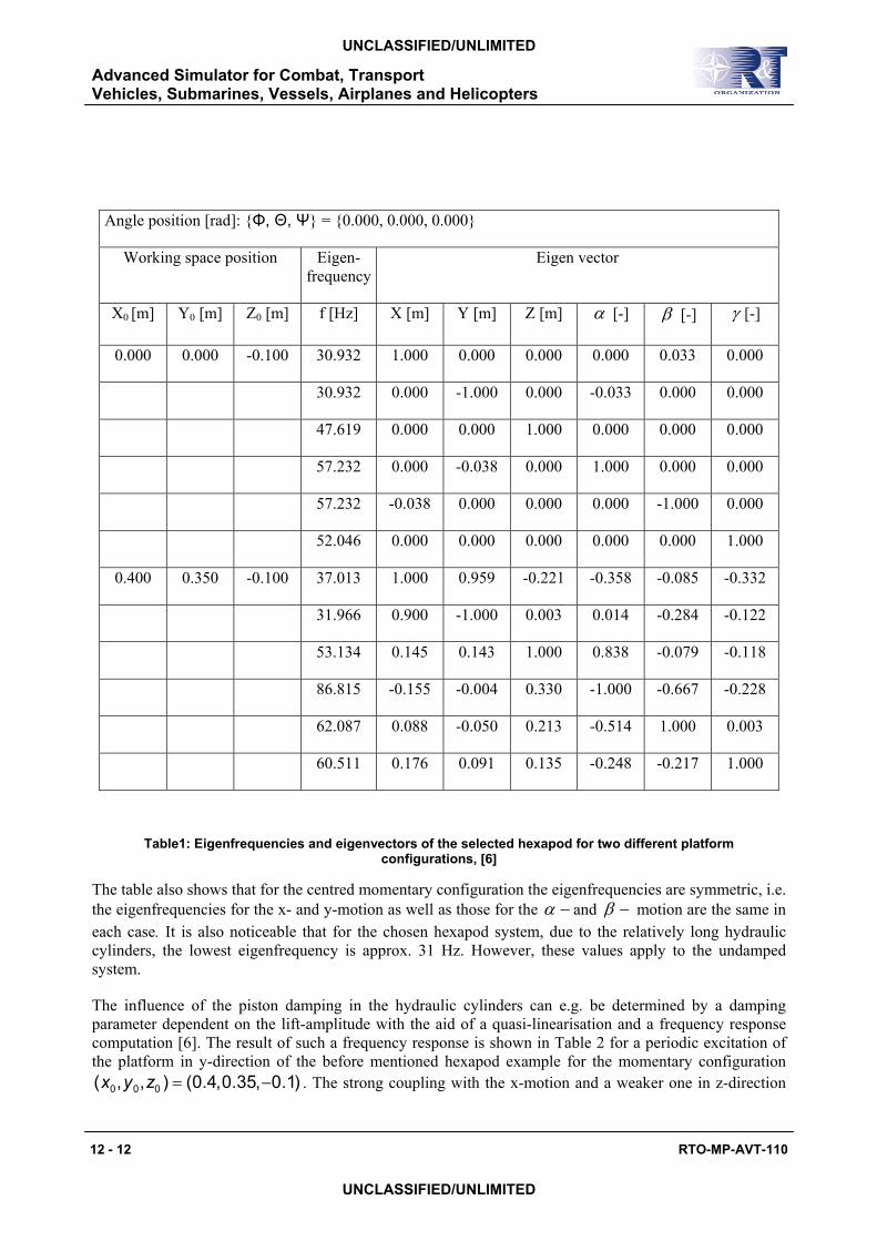
On the basis of these dynamic examinations of the nonlinear motion system it is recognizable that on the one hand the eigenfrequencies depend essentially on the momentary orientation of the platform and on the other hand additional couplings appear in the eigenvectors. Table 1 shows the influence of the momentary configuration on the motion coupling for two chosen examples. For the configuration
only relatively small amounts stand outside the main diagonal of the eigenvector matrix. The motions in the six degrees of freedom are therefore practically decoupled. In contrast, for the configuration
0 0 0( , , ) (0,0, 0.1)x y z = −
0 0 0( , , ) (0.4,0.35, 0.1)x y z = − high coupling terms are existent which are presented as errors for an aimed motion of the platform and e.g. must be compensated by an appropriate control.
RTO-MP-AVT-110 12 - 11
Ψ
Ф
Advanced Simulator for Combat, Transport Vehicles, Submarines, Vessels, Airplanes and Helicopters
UNCLASSIFIED/UNLIMITED
UNCLASSIFIED/UNLIMITED
Advanced Simulator for Combat, Transport Vehicles, Submarines, Vessels, Airplanes and Helicopters
12 - 12 RTO-MP-AVT-110
UNCLASSIFIED/UNLIMITED
UNCLASSIFIED/UNLIMITED
Angle position [rad]: {Φ, Θ, Ψ} = {0.000, 0.000, 0.000}
Working space position Eigen-frequency
Eigen vector
X0 [m] Y0 [m] Z0 [m] f [Hz] X [m] Y [m] Z [m] α [-] β [-] γ [-]
0.000 0.000 -0.100 30.932 1.000 0.000 0.000 0.000 0.033 0.000
30.932 0.000 -1.000 0.000 -0.033 0.000 0.000
47.619 0.000 0.000 1.000 0.000 0.000 0.000
57.232 0.000 -0.038 0.000 1.000 0.000 0.000
57.232 -0.038 0.000 0.000 0.000 -1.000 0.000
52.046 0.000 0.000 0.000 0.000 0.000 1.000
0.400 0.350 -0.100 37.013 1.000 0.959 -0.221 -0.358 -0.085 -0.332
31.966 0.900 -1.000 0.003 0.014 -0.284 -0.122
53.134 0.145 0.143 1.000 0.838 -0.079 -0.118
86.815 -0.155 -0.004 0.330 -1.000 -0.667 -0.228
62.087 0.088 -0.050 0.213 -0.514 1.000 0.003
60.511 0.176 0.091 0.135 -0.248 -0.217 1.000
Table1: Eigenfrequencies and eigenvectors of the selected hexapod for two different platform configurations, [6]
The table also shows that for the centred momentary configuration the eigenfrequencies are symmetric, i.e. the eigenfrequencies for the x- and y-motion as well as those for the −α and −β motion are the same in each case. It is also noticeable that for the chosen hexapod system, due to the relatively long hydraulic cylinders, the lowest eigenfrequency is approx. 31 Hz. However, these values apply to the undamped system.
The influence of the piston damping in the hydraulic cylinders can e.g. be determined by a damping parameter dependent on the lift-amplitude with the aid of a quasi-linearisation and a frequency response computation [6]. The result of such a frequency response is shown in Table 2 for a periodic excitation of the platform in y-direction of the before mentioned hexapod example for the momentary configuration
0 0 0( , , ) (0.4,0.35, 0.1)x y z = − . The strong coupling with the x-motion and a weaker one in z-direction

Advanced Simulator for Combat, Transport Vehicles, Submarines, Vessels, Airplanes and Helicopters
RTO-MP-AVT-110 12 - 13
UNCLASSIFIED/UNLIMITED
UNCLASSIFIED/UNLIMITED
can also be recognized here. The coupling with the angles of twist is only weak. It is comparatively strongest with an amplitude of approx. 0.7 mrad in ß-direction. The lowest eigenfrequency is naturally again around 31 Hz and is still much too low for a motion system that is also to represent vibration comfort up to frequencies of approx. 40 Hz.
f [Hz] X [mm] Y [mm] Z [mm] α [mrad] β [mrad] γ [mrad] IT
25.00 0.175 0.681 0.037 0.072 0.090 0.018 4
26.00 0.213 0.760 0.041 0.079 0.105 0.021 4
27.00 0.266 0.864 0.046 0.088 0.125 0.024 4
28.00 0.348 1.008 0.053 0.098 0.156 0.029 4
29.00 0.480 1.222 0.062 0.112 0.203 0.039 4
30.00 0.716 1.564 0.076 0.130 0.284 0.060 4
31.00 1.191 2.151 0.096 0.156 0.441 0.114 4
32.00 1.974 2.747 0.118 0.184 0.665 0.250 4
33.00 1.839 2.016 0.125 0.200 0.558 0.297 3
34.00 1.475 1.410 0.144 0.238 0.404 0.290 4
35.00 1.264 1.248 0.174 0.289 0.312 0.297 4
36.00 0.989 1.273 0.188 0.312 0.234 0.274 4
37.00 0.506 1.141 0.145 0.242 0.163 0.165 5
38.00 0.258 1.001 0.118 0.197 0.134 0.105 5
39.00 0.159 0.859 0.101 0.169 0.113 0.078 3
40.00 0.112 0.738 0.089 0.147 0.097 0.062 4
Table 2: Frequency response of the hexapod for the current configuration (x0,y0,z0) = (0.400,0.350, -0.100) excited in y-direction with amplitude dependent damping, [6]
The following conclusions on hexapod systems can be drawn from observations up to now:
Hexapod systems are in principle well adapted for carrying out low-frequency motions of a platform in all six degrees of freedom. The frequencies of the motions must lie so far below the lowest eigenfrequency of the entire system that this is not excited. Furthermore it must be taken into consideration:
• the possible configurations of the six coordinates of the platform to be moved result from the working space
Advanced Simulator for Combat, Transport Vehicles, Submarines, Vessels, Airplanes and Helicopters
12 - 14 RTO-MP-AVT-110
UNCLASSIFIED/UNLIMITED
UNCLASSIFIED/UNLIMITED
• limiting configurations which can lead to a blockage must be avoided
• overlapping errors as a result of kinematic couplings to the forecasted movement must be corrected
The eigenfrequencies of hexapod systems can be raised by reducing the lifting cylinders i.e. decisively by increasing the axial stiffness of the lifting cylinders. Because of the system-induced longitudinal stiffness, hydraulic cylinders for hexapod systems which e.g. are intended to carry out low-frequency motions with superimposed comfort vibrations up to approx. 40 Hz are only applicable in connection with a complex dynamic adjustment control. Electromechanical lifting cylinders can attain higher longitudinal stiffness. How high the eigenfrequencies of such a hexapod system ultimately lie, i.e. how large the relevant stiffness is, depends on the construction.
4.2 Visualisation Visualisation plays a decisive role in motion simulation. The important thing is that the visual impression is synchronized with the motion. With the present-day systems the time delay is less than 35 ms. Domes with a field of view of 360° and a resolution up to max. 1600 x 1200 pixels per channel with 15 projection channels and a refresh rate of 60 Hz are now considered to be state-of-the-art [8].
4.3 Environmental Influence Environmental influences such as engine noise, acoustic traffic signals or tyre rolling noise are reproduced by a complex acoustics system. Either digitally stored traffic noise or generated noise in accordance with the traffic environment can be shown as 3D-acoustics. For the future the simulation of climatic environmental influences such as temperature and air humidity can be visualised in the simulation cabin.
5.0 EXAMPLE FOR A MODULAR SYSTEM
With the present-day driving simulators with six degrees of freedom the central motion system is performed as a hexapod and hydraulic as well as electromechanical actuators are used. The hydraulic version offers a larger working space (up to +/- 1,80 m), a distinctly higher force vector (implementation of an original vehicle) and thus a comparatively high acceleration. However, this requires a considerable hydraulic pump capacity in order to realise the occurring piston speeds. The maximum input frequency of existing simulators is 10-15 Hz due to the piston strokes and the moved masses, in an exceptional case 20 Hz [8].
In addition the limited axial stiffness of the hydraulic cylinders and their effect on the eigenfrequencies must be observed (see 4.1).

Advanced Simulator for Combat, Transport Vehicles, Submarines, Vessels, Airplanes and Helicopters
RTO-MP-AVT-110 12 - 15
UNCLASSIFIED/UNLIMITED
UNCLASSIFIED/UNLIMITED
Figure 12: Essential components of a modular simulator system
Planar Motion System:
As the working space of hexapods is restricted, by introducing two additional horizontal motion axes there is the possibility to distinctly improve the realistic simulation when curving, changing lanes, acceleration and braking. The planar motion system is, e.g., conducted on rails. The drive is generally electromechanical, with smaller uniaxial systems also hydraulic. However, this entails a significant rise in production and running costs. A biaxial x-y motion system with a driveway of +/- 9,75 m in both directions was implemented at NADS [8].
High-frequency System:
In order to achieve the comfort aspect, an additional excitation of the simulator platform in the six degrees of freedom up to a cut-off frequency of approx. 40 Hz or higher must be carried out. This can be attained e.g. with the aid of an additional system for vibration excitation. But the ensuing dynamic repercussions on the main system (eigenvalues) demand an additional regulation input (see 4.1), e.g. the use of adaptive filters. Nowadays, for example, the excitation of a car body with four hydraulic vertical cylinders is carried out [8].
6.0 OUTLOOK
The development is heading in the direction of a simulation that is as realistic as possible. By using increasingly efficient computers and improved control algorithms, the demands on simulation can be achieved with more and more success and expanded to a broad application spectrum. The limited working space of a hexapod can be enlarged by a planar motion system. With an additional vibration system the frequency domain can be extended. The application spectrum of such a simulator ranges from the implementation of vibrations to the interactive simulation of vehicle dynamics. New, enhanced parameters on extensive test series can be compiled which then, among other things, also comprise information on rotation motions which is important e.g. for tilting trains. Furthermore, an interactive real-time simulation
Vehicle models
Wash-out
Acousticsystem
Driving scenario
Visuali-sation i Climate
control
Vehicle mock-up
Motion system
Advanced Simulator for Combat, Transport Vehicles, Submarines, Vessels, Airplanes and Helicopters
12 - 16 RTO-MP-AVT-110
UNCLASSIFIED/UNLIMITED
UNCLASSIFIED/UNLIMITED
will enable the driving dynamics of a vehicle concept to be evaluated, whereby not only the passive behaviour can be displayed but mechatronic components can also be examined with regard to their characteristics in combination with mechanics.
The comfort evaluation of real and virtual vehicles will play an increasingly important role in the future.
Acknowledgement
The author would like to thank Mr. Wolfgang Duffek who as freelancer of the DLR made valuable contributions to the paper on hand, in particular with his investigations on the kinematics and dynamics of hexapod motion systems [6].
7.0 LITERATURE
[1] E.R. Boer, N. Kuge, T. Yamamura. Affording realistic stopping behavior: A cardinal challenge for driving simulators. In Proceedings of 1st Human-Centered Transportation Simulation Conference}, Iowa City, 2001.
[2] W. Kortüm, W. Rulka, M. Spieck. Simulation of Mechatronic Vehicles with SIMPACK. MOSIS'97: Proc. of the Conference Modelling and Simulation of Systems, Ostrava, Czech Republic, 1997.
[3] H. Netter, G. Schupp, W. Rulka, L. Schroeder. New aspects of contact modelling and validation within multibody system simulation of railway vehicles. In The Dynamics of Vehicles on Roads and on Tracks, Proceedings of the 15th IAVSD-Symposium, Budapest, 1997.
[4] A. Stribersky, W. Rulka, H. Netter, A. Haigermoser. Modeling and simulation of advanced rail vehicles. In Proc. 8th IFAC Symposium on Transportation Systems, Chania, 1997.
[5] W. Krüger. Integrated design process for the development of semi-active landing gears for transport aircraft. DLR Foschungsbericht 2001-27, 2001.
[6] W.Duffek. Das Eigenverhalten eines hydraulischen Hexapoden (Teil 1), Der Arbeitsraum des Hexapoden bei Rotation in ausgelenkter Lage (Teil 2), ARNO 2002.
[7] Jane’s Simulation and Training Systems Fourteenth Edition 2001-2002.
[8] L.D. Chen, Y. Papelis, G. Watson, D. Solis. NADS at the University of Iowa: A Tool for Driving Safety Research, In Proceedings of 1st Human-Centered Transportation Simulation Conference, Iowa City, 2001.
[9] P.R. Grant, L.D. Reid. Motion Washout Filter Tuning: Rules and Requirements. Journal of Aircraft, Vol. 34 (1997), Number 2, pp 145-151.

Advanced Simulator for Combat, Transport Vehicles, Submarines, Vessels, Airplanes and Helicopters
RTO-MP-AVT-110 12 - 17
UNCLASSIFIED/UNLIMITED
UNCLASSIFIED/UNLIMITED
Detailed Analysis or Short Description of the AVT-110 contributions and Question/Reply
The Questions/Answers listed in the next paragraphs (table) are limited to the written discussion forms received by the Technical Evaluator. The answers were normally given by the first mentioned author-
speaker.
P12 J. Gschwilm ‘Advanced Simulator for Combat and Transport Vehicles , Submarines,
Vessels, Airplanes and Helicopter’, (DLR, DE) As in the papers 3 and 6 , the author draw our attention on the advantages of the virtual product development. Thanks to the use of simulation softwares and adequate modelling techniques: the author of this paper nevertheless underlined once more the necessity to assess the computation results, even if they lead to the visual perception of the dynamical consequences of motion and vibrations, and consequently to confirm the computation results , by introducing on-the field collected data and , originality of this paper, realistic experiences on a ‘universel’ simulator that has been described and analysed (in this case an electro-hydraulic static hexapod). Discussor’s name: J. Stodola Q. By your opinion, where can you feel the most serious limits of advanced realistic simulation? R. The combination of low and high frequency systems demands an additional regulation input. The control system can be combined with adaptive filters.

Advanced Simulator for Combat, Transport Vehicles, Submarines, Vessels, Airplanes and Helicopters
12 - 18 RTO-MP-AVT-110
UNCLASSIFIED/UNLIMITED
UNCLASSIFIED/UNLIMITED