advanced technology upper stages for future launchers · an advanced small tsto rocket with a...
TRANSCRIPT

Copyright © 2010 by DLR-SART. Published for the 61st International Astronautical Congress, Prague, CZ.
1
IAC-10-D2.3.1
Advanced Technology Upper Stages for Future Launchers
Martin Sippel, Anna Lang, Etienne Dumont [email protected] Tel. +49-421-24420145, Fax. +49-421-24420150
Space Launcher Systems Analysis (SART), DLR, Bremen, Germany Jens Gerstmann, Segio Montenegro
Institute of Space Systems, DLR, Bremen, Germany The paper describes two different preliminary system designs for stages employing advanced technologies: 1. An experimental micro-stage with a very small storable propellant engine for LEO applications. This vehicle is part of the multinational (France, Spain, Germany) cooperation Aldébaran investigating future options of micro-launchers. 2. An advanced small TSTO rocket with a payload capability in the range of 2000+ kg in SSO and more than 1200 kg in higher energy orbits like MTO. The first stage consists of a high pressure solid motor with a fiber casing while the upper stage is using cryogenic propellants. Synergies with other ongoing European development programs are to be exploited. In its second part the paper gives an overview on advanced cryogenic upper-stage technologies presently under investigation in Germany.
Nomenclature
D Drag N Isp (mass) specific Impulse s (N s / kg) M Mach-number - T Thrust N W weight N g gravity acceleration m/s2 m mass kg q dynamic pressure Pa v velocity m/s α angle of attack - γ flight path angle -
Subscripts, Abbreviations
AP Ammonium Perchlorate AVUM Attitude and Vernier Module (of VEGA) CAD Computer Aided Design COTS Commercial off the Shelf CUST Cryogenic Upper Stage Technologies DHS data handling systems ELV Expendable Launch Vehicle FPGA Field Programmable Gate Array GLOW Gross Lift-Off Mass GNC Guidance, Navigation, Control GTO Geostationary Transfer Orbit HTPB Hydroxyl Terminated Poly Butadiene IPA isopropyl alcohol ISS International Space Station ITAR International Traffic in Arms Regulation LAD Liquid Acquisition Device LEO Low Earth Orbit LH2 Liquid Hydrogen LOX Liquid Oxygen MEOP Maximum Expected Operating Pressure MMH Monomethyl Hydrazine MR Mixture Ratio MTO Medium Transfer Orbit
SI Structural Index (mdry / mpropellant) SRM Solid Rocket Motor SSO Sun Synchronous Orbit TRL Technology Readiness Level TSTO Two Stage to Orbit VEGA Vettore Europeo di Generazione Avanzata VENUS VEGA New Upper Stage cog center of gravity sep separation
1 INTRODUCTION The payload performance and flexibility of a launch vehicle is strongly dependent on the design of its upper stage. Therefore, significant research effort is spent in Germany on the improvement of all such future types. A research cooperation of German launcher industry, university academia, and DLR has been initiated to work jointly on various identified needs of advanced cryogenic upper-stage technologies. Different studies are also ongoing in the pre-definition of configurations with storable propellants. SART activities on the investigation and preliminary design of upper stages are run in European international cooperation, in a German national cooperation with industry, and as DLR internally funded system studies.
2 ALDÉBARAN: MICRO UPPER STAGE WITH STORABLE PROPELLANTS
Aldébaran is the name chosen for a "launcher system" demonstrator project initiated by CNES. The project is aimed at developing a flight demonstrator by focusing certain activities involved in the preparation of future launch vehicles. The first launch was expected to take place around 2015. The Aldébaran project has been co managed by national agencies and institutes (CDTI in Spain, DLR in Germany and CNES in France) [1]. Several Aldébaran concepts have been analyzed in the “Phase 0” during 2008. In this period DLR-SART
focused on semi-reusable launcher concepts [2] and advanced upper stages with an innovative effusion cooled ceramic combustion chamber [3]. A down-selection process has been applied in Aldébaran taking into account the benefit of the proposed new technologies for the future launch systems, but also the interest of the partners for instance by taking advantage of research activities already foreseen [1]. Three concepts have been retained for the originally planned “phase A”. One of them is an airborne configuration launched from a military aircraft [1]. The Aldébaran project is now on hold due to budget cuts or a re-orientation of available launcher system development funds. Nevertheless, the already obtained results on potential advanced upper stage configurations studied at DLR in 2010 are published here.
2.1 Experimental Air-Launched Concept AML-X This concept was proposed and originally studied by EADS-CASA and Dassault. The main characteristics were according to [1]:
- A small launch vehicle airborne below a combat aircraft, weighting about 6 T for the linear 2 stages demonstrator, and up to 11 T for the operational derived version.
- A launch procedure using high energy maneuver capability of the carrier aircraft: separation at about 40° flight path angle, Mach 0.8 and above 15 km altitude.
- A 2 stages (solid & liquid propellants) demonstrator vehicle compatible with existing combat aircrafts available in Europe (Eurofighter and Rafale).
The first stage uses about 2 tons of solid propellant either conventional type (ammonium perchlorate with HTPB), or using new formulations (HMX, Oxalane - ®SNPE). The final choice will depend on the real interest for the next evolutions of launcher systems. It will also depend on the technological maturity which could be demonstrated prior to the development of such systems. The processes of loading will also be taken into account in the technology selection. Other technological improvements are foreseen for the casing (high strength carbon fibre or shock resistance material), for the thermal protections (low density insulation material), for the nozzle and activation system (low cost and low erosion CC composite throat, extra light structures, EMA activation, etc.). The AML/aircraft should be deployable from any location in the world with a compatible airport. During the Aldébaran study, four suitable locations have been considered [4]:
- Mont de Marsan, France for SSO inclinations - Kourou / French Guyana for every direct
inclinations and SSO - Gran Canaria, Spain for medium inclinations to
SSO - Andoya and / or Svalbard, Norway for high
inclinations to SSO
The conditions at launcher separation from the aircraft should be [4]:
- Altitude > 15 000 m - Mach > 0.7 - Flight Path angle > 45°
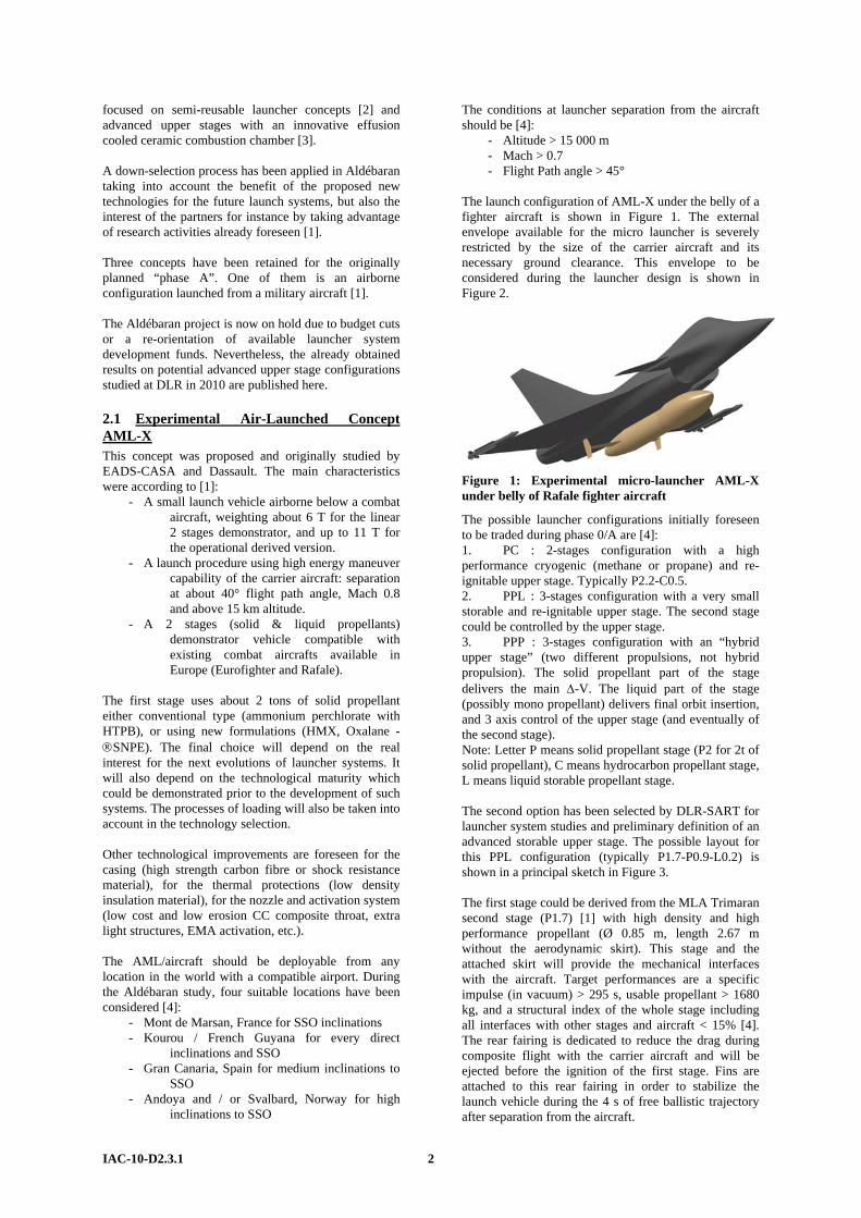
The launch configuration of AML-X under the belly of a fighter aircraft is shown in Figure 1. The external envelope available for the micro launcher is severely restricted by the size of the carrier aircraft and its necessary ground clearance. This envelope to be considered during the launcher design is shown in Figure 2.
Figure 1: Experimental micro-launcher AML-X under belly of Rafale fighter aircraft
The possible launcher configurations initially foreseen to be traded during phase 0/A are [4]: 1. PC : 2-stages configuration with a high performance cryogenic (methane or propane) and re-ignitable upper stage. Typically P2.2-C0.5. 2. PPL : 3-stages configuration with a very small storable and re-ignitable upper stage. The second stage could be controlled by the upper stage. 3. PPP : 3-stages configuration with an “hybrid upper stage” (two different propulsions, not hybrid propulsion). The solid propellant part of the stage delivers the main Δ-V. The liquid part of the stage (possibly mono propellant) delivers final orbit insertion, and 3 axis control of the upper stage (and eventually of the second stage). Note: Letter P means solid propellant stage (P2 for 2t of solid propellant), C means hydrocarbon propellant stage, L means liquid storable propellant stage. The second option has been selected by DLR-SART for launcher system studies and preliminary definition of an advanced storable upper stage. The possible layout for this PPL configuration (typically P1.7-P0.9-L0.2) is shown in a principal sketch in Figure 3. The first stage could be derived from the MLA Trimaran second stage (P1.7) [1] with high density and high performance propellant (Ø 0.85 m, length 2.67 m without the aerodynamic skirt). This stage and the attached skirt will provide the mechanical interfaces with the aircraft. Target performances are a specific impulse (in vacuum) > 295 s, usable propellant > 1680 kg, and a structural index of the whole stage including all interfaces with other stages and aircraft < 15% [4]. The rear fairing is dedicated to reduce the drag during composite flight with the carrier aircraft and will be ejected before the ignition of the first stage. Fins are attached to this rear fairing in order to stabilize the launch vehicle during the 4 s of free ballistic trajectory after separation from the aircraft.
IAC-10-D2.3.1 2

1410 mm 2341 mm 2527 mm 436 mm
Ø 850 mm Ø1015 mm*
12°
Figure 2: External envelope of experimental micro-launcher AML-X [4]
Payload
Wing
Fin AerodynamicFaring
P1.7 P0.9 L0.2
Figure 3: Sketch of experimental micro-launcher AML-X in drop configuration
The second stage P0.9 could be likely an ATK Star37XFP. A trade off is required to define if the stage should be controlled by itself (pitch, yaw, roll) of via another stage (in that case the second stage will have a fixed nozzle). The main targeted characteristics are more than 900 kg of solid propellant, more than 290 s of vacuum specific impulse, and less than 11% of total structural index for the stage with all equipments and interfaces. A maximum length of the stage of 1400 mm and a maximum diameter of 850 mm for the rear part and 1015 mm for the front part (see Figure 2!) are to be considered [4].
2.2 Storable Upper Stage L0.2 According to the requirements document [4] the third stage is foreseen to provide an important part of the mission Δ-V (more than 3000 m/s), to accomplish the final orbit insertion (in case of a multiboost injection strategy), and to provide an additional Δ-V for de-orbit or distancing to a graveyard orbit. The main avionics equipment is to be attached to this stage. The third stage should also have a control capability in pitch yaw and roll for itself, and potentially also for the second stage. The main requirements are defined in [4] as:
- More than 200 kg of liquid propellant - More than 315 s of vacuum specific impulse - Total thrust about 2 kN (+/- 0.5 kN). Multiple
engines configurations could be an option. - A low structural index is one of the major
challenges of this stage. Less than 40% is the objective for the structural index including all inert parts injected into orbit
- A maximum length of 750 mm
- A maximum diameter of 1015 mm Based on the above list of requirements from CNES [4], a launcher pre-design process has been initiated by DLR-SART. In a first step the minimum requirements of all three stages have been used without any further data cross check in an ascent trajectory optimization. This simulation included also the 4 s of unpowered drop phase after launcher release from the aircraft in order to get realistic initial conditions for the optimizer. These initial flight conditions for the propulsion phase are listed in Table 1.
Table 1: initial flight conditions for propulsive phase [6]
The early analysis demonstrated that under the minimum assumptions of the requirements document, a payload of about 24 kg might be released by the AML-X PPL into a 400 km circular LEO with 98° inclination [5]. This performance is in sufficient agreement with the required value that a more detailed upper stage pre-design and configuration trade-off have been started. The upper stage of AML-X is using the storable propellant combination for which the best experience exists in Europe: MMH / N2O4. Only pressure fed configurations are regarded to limit the overall complexity of the small system. A storable propellant engine of approximately 2 kN thrust currently does not exist in Europe. Some
Altitude 15.49 km Velocity 173 m/s Flight path angle γ 36.28°
IAC-10-D2.3.1 3

preliminary definition work is running in the German VENUS activities on a potential new engine for VEGA’s AVUM. However, its actual development is far from certain and the VENUS study’s tendencies are now oriented towards an increased thrust level. Thus, DLR-SART independently defined a generic 1.5 kN storable engine for the AML-X micro launcher application. In addition the clustering of 3 in-production European bi-propellant thrusters in the 400 N class is investigated. These are the Astrium S400-12 and S400-15 [7].
In a stage architecture trade-off, these 3 engines are combined with suitable tank arrangements. Table 2 gives an overview of the different investigated upper stage configurations. Due to the different possible engines, the propellant masses and the feasibility of the tank configurations vary. Before the tank accommodation is verified by a CAD-model, the needed tank geometry is checked by the fast DLR program PMP for the pre-sizing of propellant tank-, feed- and pressurization systems.
Table 2: Initial data of investigated AML-X upper stage configurations [6]
In the preliminary analysis phase, the performances of the configurations A – E are studied without a structural analysis based on nothing more than empirical mass relationships. Configuration C’s propellant mass of 235 kg in Table 2 is very preliminary because the common bulkhead between the fuel and the oxidizer is not yet designed. The configuration has to be studied in more detail in the future [6]. Preliminary payload performances from trajectory optimizations of the configuration A – E are listed in Table 3. The configuration trade-off shows that configuration E is the most promising one. Thus, the preliminary upper stage lay-out is continued with the E-configuration. An analysis in reference 6 shows that for configuration E with three S400-15 engines, the maximum payload mass is achieved at a propellant loading of only 185 kg. This value is slightly below the requirement of more than 200 kg defined in [4]. To receive a better volume
margin, in the study configuration E is calculated with a nominal ascent propellant mass of 180 kg.
Configuration 3rd stage mass 3rd stage SI Mass P/L
A 306.7 kg 50.8 % 14.5 kg B 327.1 kg 48.7 % 17.1 kg D 298.1 kg 46.54 % 21.1 kg E 300.4 kg 47.7 % 21.3 kg
Table 3: Preliminary performances of configurations A, B, D, E [6]
With its three engines, configuration E requires a special tank accommodation with one conical tank for the oxidizer in the middle and three cylindrical tanks for the fuel arranged around. The fuel tanks are connected via a tank support structure to the oxidizer tank in the middle, whereas the oxidizer tank is connected by beams to the
Configuration engine Number of engines total Thrust Isp, vacuum Propellant
mass Tank types and arrangements
A Generic SART
assumption1 1.5 kN 315 s 200 kg 4 cylindrical z
y
z
y
x
z
x
z
B Generic SART
assumption1 1.5 kN 315 s 220 kg 6 cylindrical
z
y
C Generic SART
assumption1 1.5 kN 315 s ca. 235 kg Toroidal with
common bulkhead
x
z
z
y
D S400-12 3 1.26 kN 318 s 200 kg 3 cylindrical; 1 conical
z
y
z
y
z
yz
y
z
y
z
y
E S400-15 3 1.275 kN 325 s 200 kg 3 cylindrical; 1 conical
z
y
xz
IAC-10-D2.3.1 4

main ring of the support structure. This ring also separates the fairing from the 2/3-interstage (Figure 4). All loads before stage separation due to normal loads during aircraft carrying or afterwards by the axial rocket acceleration are transmitted through the main ring and the interstage. The payload adapter as well as the vehicle equipment bay (shaded semi-transparent in red in Figure 4) is installed above the main ring.
Figure 4: Isometric view of preliminary upper stage design for configuration E [6]
The available payload volume is about Ø 500 mm x 500 mm which should be sufficient for the micro-satellite application. Current spacecraft data handling systems (DHS) are primary computer-oriented building computer-centric systems. In this model the central computer has to provide high computing power, large memory, high dependability, fault tolerance management, and a significant number of input/output (I/O) connections. This makes the central computer development very difficult. An innovative avionics concept is proposed for the AML-X launcher.
Figure 5: CAD drawing of upper stage configuration E under fairing and interstage [6]
An advanced approach of DLR aims at building a network centric system where the central element is not a computer but a powerful spacecraft area network (SCAN). The network is built using reliable intelligent switches. By the definition of such a SCAN three of the greatest problems faced with the avionics development of every new spacecraft are targeted: 1. The huge cost and long development time due just to the interfaces specification. DLR’s counter-strategy is what is called network centric computing which creates a spacecraft area network to which all devices and
computers are attached. Reference implementations already exist which may be distributed as open source for both: FPGA IP cores and software middleware.
Figure 6: Network structure of the DHS
2. The extremely high costs and almost no post-development reuse of the on-board computers. Normally I/O-devices are attached directly to the computer and each mission has different I/O-devices. In the DLR concept, the on-board computer will not have any devices attached to it (it performs just computing and storage functions) therefore the same computer may be used in many different missions which have different device configurations and different I/O-devices. These are all truly network devices and are attached only to the network. 3. ITAR restrictions and low performance of European space-qualified hardware: The new approach achieves reliability using non-reliable COTS-components attached to a reliable network. Such COTS-components have no ITAR restrictions and an order-of-magnitude higher performance than space-qualified ones. Through the advanced avionics approach, DLR expects to obtain a very high performance, low cost core-avio-nics system. Its distributed character allows distributed development. It has a very high adaptability and flexibility. Tasks may be migrated from one computing node to another in order to balance the load and to compensate failures. The same communication protocol for software applications is used for the network and for the devices. All communications in the system are based on the publisher/subscriber protocol (in software and in hardware). Publishers make messages public under a given topic. Subscribers (zero, one or more) to a given topic get all messages which are published under this topic. To establish a transfer path, both the publisher and the subscriber must share the same topic. A topic is represented by a topic ID and a data type. The network is based on a publisher/subscriber protocol which is implemented in DLR’s open source RODOS operating system [8] as a software middleware for the software tasks and in a FPGA as a middleware switch for hardware devices and to interconnect computing nodes. The central component of the network centric concept is the network itself. If it fails, the system fails. Therefore, to create a reliable network, redundant robust components with ultra fast recovery time are used. The building block of the network is the middleware switch, whose logical view is very similar to a software middle-ware.
IAC-10-D2.3.1 5

The micro-launcher’s advanced avionics system contains three on-board computers kept hot redundant for launch and for critical maneuvers (50 MIPS, 16 MBytes RAM), two network switches kept hot redundant with up to 32 channels (see Figure 6). Total mass of the avionic system is no more than a few kilogram or around 10 kg if the hardware is stored inside a box. Overall upper stage dry mass without fairing including 10 % margin is estimated at almost 72 kg and the stage’s GLOW without payload is 277 kg [6].
2.3 AML-X Micro-Launcher Payload Perfor-mance and Critical Issues The trajectory profile has been optimized for performance considering the initial flight conditions for the propulsion phase as listed in Table 1. The first stage solid motor accelerates up to Mach 6 in about 44 s, followed by the second stage motor for another 67 s reaching 4.5 km/s. The maximal dynamic pressure is about 30 kPa while the assumed thrust profile of the second stage causes high axial loads slightly beyond 10 g. As the motors are not finally selected, the actual could still change significantly. The fairing separation takes place at about 143 s during the 3rd stage burn. The liquid upper stage continues its mission until injection into a transfer orbit of 76.3 x 405.5 km. After a ballistic arc the S400 engine is to be reignited to achieve a 400 km circular orbit. With a propellant reserve of 3.3 kg for stage de-orbiting, a payload mass of 16.7 kg is achievable with the mass assumptions of section 2.2. This value is below the previous result presented in Table 3 and also below the requirement. The reason for this unfortunate situation is the new upper stage mass estimation based on the more detailed stage architecture defined after the configuration selection. Fairing and avionics masses in a VEB-box are still relatively conser-vative and offer some potential for improvement. Approximately a 25 kg payload is the upper limit for the AML-X experimental micro-launcher into an SSO. A major critical point of all investigated upper stage configurations is the close integration of rocket engines and propellant tanks forced by the strict volume and length limitations. The engine nozzles are radiatively cooled and transfer a significant amount of heat into the tanks. Nevertheless cooling could be insufficient for engines designed for different surroundings. More detailed analyses would be required in the future to check on the viability of the current design solution. Engines submerged into the tanks and hence convectively cooled as on some Soviet submarine-launched ballistic missiles could be a technical option. However, then such innovative engine types will have to be developed in Europe only for the tiny market of the micro-launcher, which is unlikely.
3 ADVANCED SMALL TSTO LAUNCHER The small launcher VEGA with an advanced solid propellant first stage, P80, will become operational within the next few years. VEGA consists of three solid rocket motors and a small liquid propulsion module for
precise orbit injection called AVUM. Germany is not participating in this launcher development project. However, the need for a performance upgrade of VEGA before the end of the decade has already been identified. A simplification of the overall lay-out combined with a reduction in the total number of stages and the introduction of a larger liquid propellant upper stage could be an interesting configuration. Several options of different propellant combinations and engines have been assessed in the German VENUS study. This work has been run as a joint DLR-SART – EADS Astrium effort funded by the DLR space agency. The VENUS study, initiated in mid 2007 and running until 2011, is currently focusing on storable propellant upper stages. However, 6 different liquid engine options with three different propellant combinations have been analyzed by SART so far. Major results have been published in [9, 10, 11]. Trajectory and performance analysis of all the VENUS upper stage configurations is made, targeting the VEGA reference mission: a circular orbit with an altitude of 700 km and an inclination of 90°. After injection in a transfer orbit and succeeding the ballistic phase, an apogee circularization maneuver takes place. Version “F” of VENUS, as investigated in 2007, intends to replace the current Vega Z23 solid 2nd stage, Vega Z9A solid 3rd stage, and the AVUM 4th stage by a single new cryogenic (LOX/LH2) propellant stage equipped with a 180 kN Vinci engine [9]. For the VENUS F TSTO version, the optimum upper stage fuel mass has been found to be around 16000 kg. The F version has a relatively low lift off mass of below 120 tons, requiring an adjustment of the P80 end burn profile in order not to exceed 6 g axial acceleration. Payload capacity in the polar VEGA orbit could reach almost 2600 kg [9]. The VENUS F TSTO launcher of 2007 consisting of P80 and an H16 liquid stage showed very interesting performance characteristics. This small TSTO has the additional advantage of being very compact and having the shortest length of all investigated versions presented in [9, 12].
3.1 New TSTO configurations with P100 first stage A future increase in the size of VEGA’s first stage P80 is already under discussion before its inaugural flight. The propellant loading, which has been calculated but not yet tested, could reach almost 100 tons (P100) for the first stage motor. More detailed investigations of the VENUS F TSTO, taking into account more powerful first stages like P100, were already proposed in references 10 and 11. The preliminary design of such an advanced small TSTO was initiated at DLR early this year. An important requirement to be considered for this launcher is the implementation of European launcher hardware already existing or under development. This approach should allow for reducing development cost, but even more importantly, to raise production numbers of components and thus decrease manufacturing cost and enhance quality. The main propulsion system should
IAC-10-D2.3.1 6

include the advanced, expander cycle VINCI upper stage rocket engine currently under development for Ariane 5 ME. Some parts of the propellant feed and tank pressurization system, as well as substructures and equipment of this large upper stage might also be used again on the smaller TSTO. However, such dual application of similar components on different launchers is not always easy to be realized. One aim of this study is to identify potential design synergies for advanced cryogenic stages to be later critically analyzed for their feasibility. A major challenge of an upper stage pre-design and propellant loading optimization is the reliable estimation of the stage’s burn-out mass. Previous studies on advanced launchers showed significant alterations in stage dry masses during preliminary design [10, 11]. The TSTO pre-design has been started with an evaluation of existing cryogenic upper stages. Observed trends should be used in a suitable selection of the stage mass necessary for a viable assessment of the optimum propellant loading. Figure 7 shows the evolution of the upper stage structural index (SI) as a function of nominal propellant loading. The results are scattering as expected due to different stage architectures and also due to the uncertainty in available data. Nevertheless a clear tendency can be observed. The blue line in Figure 7 represents an exponential regression approximation of all stages in the range 8 to 30 tons of propellant loading with a minimization of statistical errors. The yellow and red line is each representing an arbitrarily defined upper and lower limit for the structural index. Some stages are found even outside of the extreme lines. These stages, however, are of an architecture different to that intended for the small TSTO.
structural index [ - ]
0
0.05
0.1
0.15
0.2
0.25
0.3
5 000 10 000 15 000 20 000 25 000 30 000propellant mass [kg]
Figure 7: Evolution of structural index (without engine and fairing) based on data of existing cryogenic upper stages
Based on the three trend lines in Figure 7, three different optimum upper stage propellant loadings have been calculated; each for its maximum payload into the VEGA reference orbit. The range of interesting propellant mass is found between 14000 kg (upper SI boundary) and 19000 kg (lower SI boundary). A structural index following the blue line would have an optimum propellant loading of approximately 17000 kg. As the actual development of SI as a function of propellant mass is still unknown, a preliminary stage architecture design has been started for 14, 17, and 20 tons LOX-LH2 mass and with two different tank
configurations for each of them. A separate tank architecture, as shown in Figure 8, is regarded together with a common bulkhead design.
Figure 8: Preliminary architecture of advanced small launcher TSTO with H17 upper stage on top of P100
All investigated launchers are very compact and are in the same range of length as the current VEGA. The cryogenic stage’s outer diameter is kept at the same value as the P100 motor beneath. The faring is reused from VEGA but might also be enlarged to 3 m external diameter. The structural pre-sizing based on ascent trajectory loads and the calculation of the propellant feed and pressurization system is ongoing. Besides the polar reference mission, other trajectories to LEO or high energy orbits like GTO or MTO will be considered for realistic assumptions of system demands and loads.
3.2 TSTO Payload Performance and Critical Issues Although the stage sizing process is not yet completed, separated payload masses for different orbits have already been calculated with the structural index assumption of the blue line in Figure 7. Note that the amount of fuel needed for stage deorbiting is already considered in the data provided in Table 4. The polar and the ISS mission are calculated with two engine burns while MTO and GTO are reached by direct injection single burn of the upper stage. Different stage MECO masses due to the engine re-ignition requirement and propellant conditioning in ballistic phases are not yet considered, but will be subject to later studies.
IAC-10-D2.3.1 7
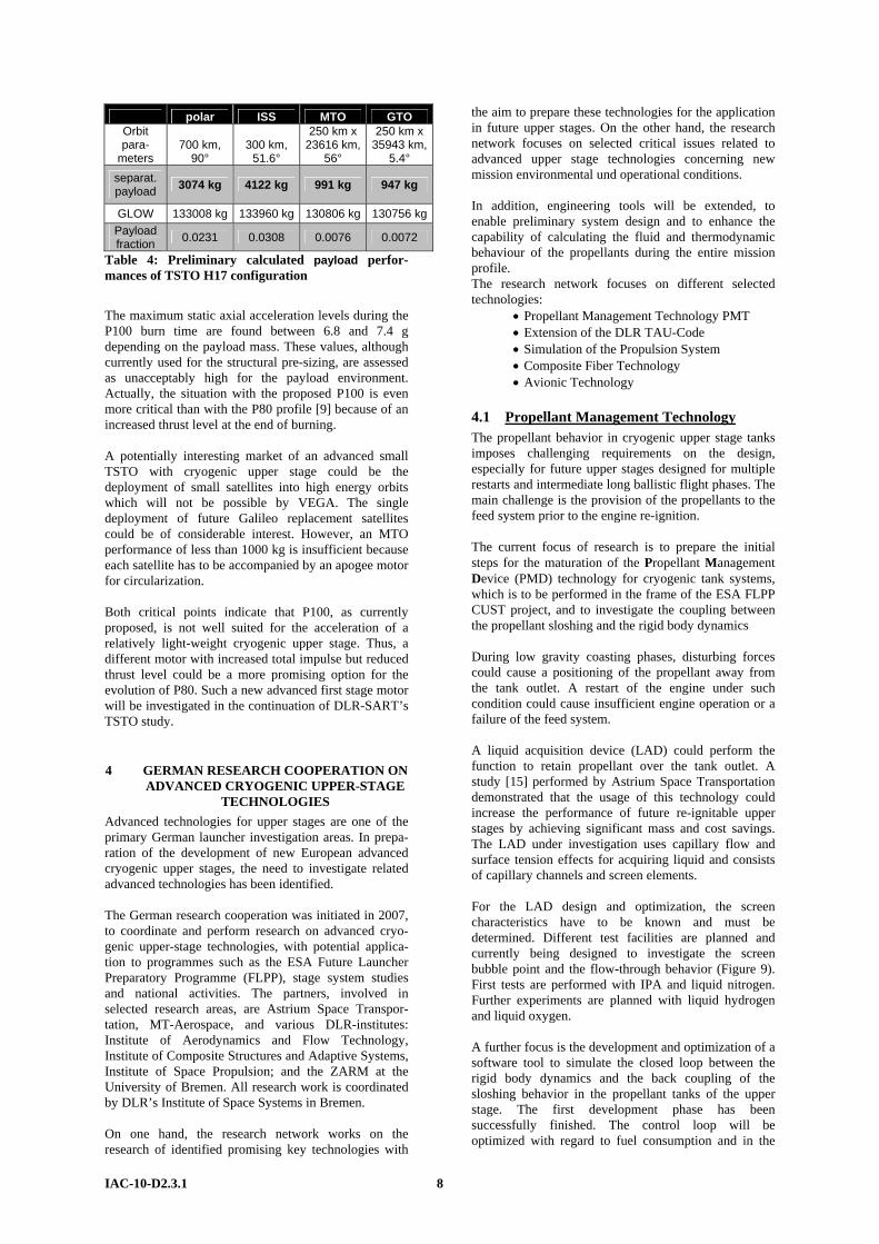
polar ISS MTO GTO Orbit para-
meters 700 km,
90° 300 km,
51.6°
250 km x 23616 km,
56°
250 km x 35943 km,
5.4° separat. payload 3074 kg 4122 kg 991 kg 947 kg
GLOW 133008 kg 133960 kg 130806 kg 130756 kgPayload fraction 0.0231 0.0308 0.0076 0.0072
Table 4: Preliminary calculated payload perfor-mances of TSTO H17 configuration
The maximum static axial acceleration levels during the P100 burn time are found between 6.8 and 7.4 g depending on the payload mass. These values, although currently used for the structural pre-sizing, are assessed as unacceptably high for the payload environment. Actually, the situation with the proposed P100 is even more critical than with the P80 profile [9] because of an increased thrust level at the end of burning. A potentially interesting market of an advanced small TSTO with cryogenic upper stage could be the deployment of small satellites into high energy orbits which will not be possible by VEGA. The single deployment of future Galileo replacement satellites could be of considerable interest. However, an MTO performance of less than 1000 kg is insufficient because each satellite has to be accompanied by an apogee motor for circularization. Both critical points indicate that P100, as currently proposed, is not well suited for the acceleration of a relatively light-weight cryogenic upper stage. Thus, a different motor with increased total impulse but reduced thrust level could be a more promising option for the evolution of P80. Such a new advanced first stage motor will be investigated in the continuation of DLR-SART’s TSTO study.
4 GERMAN RESEARCH COOPERATION ON ADVANCED CRYOGENIC UPPER-STAGE
TECHNOLOGIES Advanced technologies for upper stages are one of the primary German launcher investigation areas. In prepa-ration of the development of new European advanced cryogenic upper stages, the need to investigate related advanced technologies has been identified. The German research cooperation was initiated in 2007, to coordinate and perform research on advanced cryo-genic upper-stage technologies, with potential applica-tion to programmes such as the ESA Future Launcher Preparatory Programme (FLPP), stage system studies and national activities. The partners, involved in selected research areas, are Astrium Space Transpor-tation, MT-Aerospace, and various DLR-institutes: Institute of Aerodynamics and Flow Technology, Institute of Composite Structures and Adaptive Systems, Institute of Space Propulsion; and the ZARM at the University of Bremen. All research work is coordinated by DLR’s Institute of Space Systems in Bremen. On one hand, the research network works on the research of identified promising key technologies with
the aim to prepare these technologies for the application in future upper stages. On the other hand, the research network focuses on selected critical issues related to advanced upper stage technologies concerning new mission environmental und operational conditions. In addition, engineering tools will be extended, to enable preliminary system design and to enhance the capability of calculating the fluid and thermodynamic behaviour of the propellants during the entire mission profile. The research network focuses on different selected technologies:
• Propellant Management Technology PMT • Extension of the DLR TAU-Code • Simulation of the Propulsion System • Composite Fiber Technology • Avionic Technology
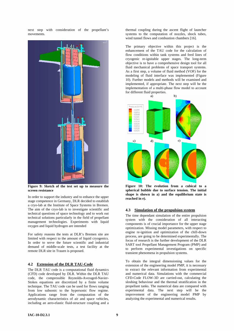
4.1 Propellant Management Technology The propellant behavior in cryogenic upper stage tanks imposes challenging requirements on the design, especially for future upper stages designed for multiple restarts and intermediate long ballistic flight phases. The main challenge is the provision of the propellants to the feed system prior to the engine re-ignition. The current focus of research is to prepare the initial steps for the maturation of the Propellant Management Device (PMD) technology for cryogenic tank systems, which is to be performed in the frame of the ESA FLPP CUST project, and to investigate the coupling between the propellant sloshing and the rigid body dynamics During low gravity coasting phases, disturbing forces could cause a positioning of the propellant away from the tank outlet. A restart of the engine under such condition could cause insufficient engine operation or a failure of the feed system. A liquid acquisition device (LAD) could perform the function to retain propellant over the tank outlet. A study [15] performed by Astrium Space Transportation demonstrated that the usage of this technology could increase the performance of future re-ignitable upper stages by achieving significant mass and cost savings. The LAD under investigation uses capillary flow and surface tension effects for acquiring liquid and consists of capillary channels and screen elements. For the LAD design and optimization, the screen characteristics have to be known and must be determined. Different test facilities are planned and currently being designed to investigate the screen bubble point and the flow-through behavior (Figure 9). First tests are performed with IPA and liquid nitrogen. Further experiments are planned with liquid hydrogen and liquid oxygen. A further focus is the development and optimization of a software tool to simulate the closed loop between the rigid body dynamics and the back coupling of the sloshing behavior in the propellant tanks of the upper stage. The first development phase has been successfully finished. The control loop will be optimized with regard to fuel consumption and in the
IAC-10-D2.3.1 8
next step with consideration of the propellant’s movements.
Figure 9: Sketch of the test set up to measure the screen resistance
In order to support the industry and to enhance the upper stage competence in Germany, DLR decided to establish a cryo-lab at the Institute of Space Systems in Bremen. The aim of the cryo-lab is to investigate scientific and technical questions of space technology and to work out technical solutions particularly in the field of propellant management technologies. Experiments with liquid oxygen and liquid hydrogen are intended For safety reasons the tests at DLR’s Bremen site are limited with respect to the amount of liquid cryogenics. In order to serve the future scientific and industrial demand of middle-scale tests, a test facility at the remote DLR site in Trauen is proposed.
4.2 Extension of the DLR TAU-Code The DLR TAU code is a computational fluid dynamics (CFD) code developed by DLR. Within the DLR TAU code, the compressible Reynolds-Averaged-Navier-Stokes equations are discretized by a finite volume technique. The TAU code can be used for flows ranging from low subsonic to the hypersonic flow regime. Applications range from the computation of the aerodynamic characteristics of air and space vehicles, including an aero-elastic fluid-structure coupling and a
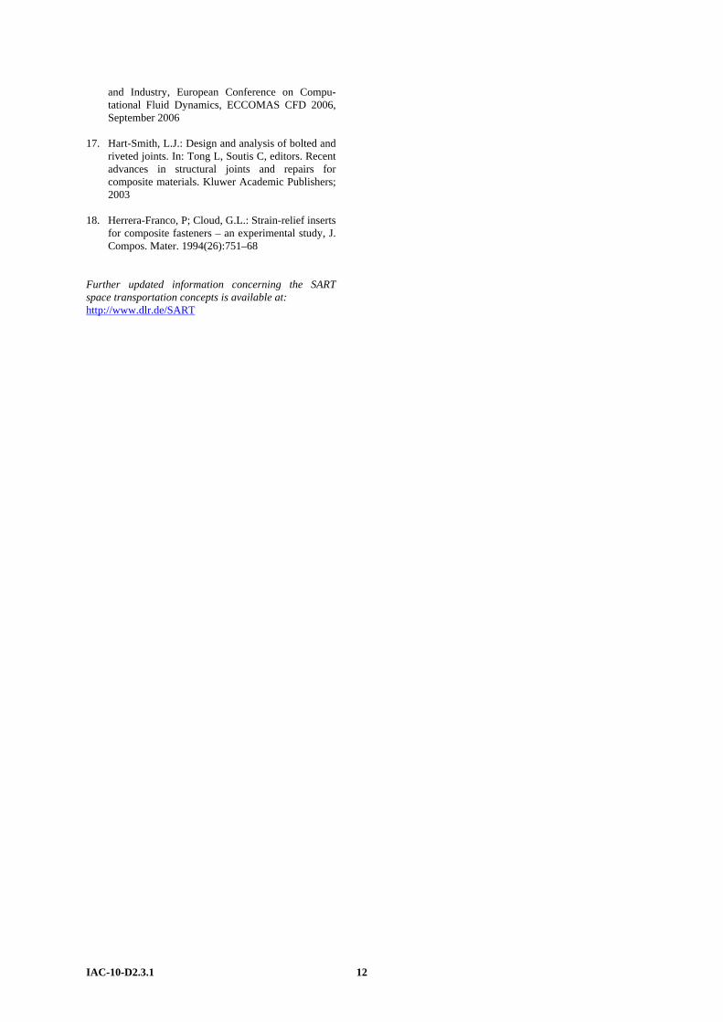
thermal coupling during the ascent flight of launcher systems to the computation of nozzles, shock tubes, wind tunnel flows and combustion chambers [16]. The primary objective within this project is the enhancement of the TAU code for the calculation of flow conditions within tank systems and feed lines of cryogenic re-ignitable upper stages. The long-term objective is to have a comprehensive design tool for all fluid mechanical problems of space transport systems. As a first step, a volume of fluid method (VOF) for the modeling of fluid interface was implemented (Figure 10). Further models and methods will be examined and implemented, if appropriate. The next step will be the implementation of a multi-phase flow model to account for different fluid properties.
Figure 10: The evolution from a cubical to a spherical bubble due to surface tension. The initial shape is shown in a) and the equilibrium state is reached in e).
4.3 Simulation of the propulsion system The time dependant simulation of the entire propulsion system with the consideration of all interacting components is of crucial importance for the upper stage optimization. Missing model parameters, with respect to engine re-ignition and optimization of the chill-down process, are going to be determined experimentally. The focus of research is the further development of the DLR SART tool Propellant Management Program (PMP) and to perform experimental investigations on specific transient phenomena in propulsion systems. To obtain the integral dimensioning values for the extension of the engineering model PMP, it is necessary to extract the relevant information from experimental and numerical data. Simulations with the commercial CFD-Code FLOW-3D are carried-out, calculating the sloshing behaviour and the thermal stratification in the propellant tanks. The numerical data are compared with experimental data. The next step will be the improvement of the engineering model PMP by analyzing the experimental and numerical results.
IAC-10-D2.3.1 9

Future work will contain the modeling of stratification in real launch vehicle tanks using FLOW-3D and comparing the results with the engineering model implemented in PMP. Ideally, an engineering model for the estimation of the pressure drop’s integral effect during cryogenic sloshing can be developed from experimental and numerical data. For the development of re-ignitable upper stage engines, the modeling of two-phase flow phenomena and water hammer effects in the feed lines and the so called flashing phenomenon, the flash vaporization during injection of liquid oxygen into the combustion chamber, are of particular interest and in the focus of the current research. A new test bench with new test hardware is planned and currently being designed to study the mentioned phenomena. In addition efforts are also directed to the numerical simulation of transient phenomena. The aim is to extend an existing lumped parameter model. The simulation efforts will concentrate on two-phase phenomena and heat transfer effects in fluid flow transients in pipelines.
4.4 Composite Fiber Technology With the exception of the propellant tanks, all primary components of advanced upper stages consist of composite fibre structures. One of the main methods used for joining composite components for aerospace applications is mechanical fastening. Mechanically fastened joints have the advantages of reliability, detachability and the ability to inspect, and represent a well established and well-known method. However, to reach a satisfactory structural coupling efficiency with composite materials is much more challenging than it is for metals due to the low bearing and shear strengths, the higher notch sensitivity, the dependence of the joint strength on the laminate configuration, and the influence of environmental effects on the mechanical behavior of the joint [17, 18]. These properties represent a limiting factor on the structural performance of composite structures. High temperature gradients together with high mechanical loads imply a huge challenge for the design.
Figure 11: Interlaminar (titanium layer) thermal residual strength
A first analysis was performed to evaluate the usage of CFRP/metal hybrid laminates for upper stage structures (Figure 11 and Figure 12). The selection of the metal to be used in the locally reinforced region of the laminate is of primary importance for the efficiency of the
technology proposed. Taking into account that titanium has good specific mechanical properties, it is electro-chemically compatible with carbon, and has a relatively low coefficient of thermal expansion, this material seems to be a potential candidate.
Figure 12: Displacement strains in the titanium layer
A further point of interest is the topic of damage tolerance. The aim is to develop numerical models to calculate the effects of delamination, debonding and impact on damage growth and residual strength. In order to validate and extent the numerical models, a set of samples are specified and currently in preparation. The samples are prepared with specific and defined damages, like delamination and debonding.
4.5 Avionics Technology This research area includes two aspects: core avionics system and sensor technology. The aim of the first aspect is to develop a flexible, fault-tolerant, dependable and high reliability core avionics system. The system shall also be easily adaptable to different future mission scenarios. Besides this advan-tage, the mass, cost, and power consumption of the new system shall also be reduced in comparison to today’s upper stage core avionics systems and the design shall be “ITAR free” to the most extent possible. This avionics concept has been proposed for the AML-X upper stage and is already briefly described in section 2.2 on page 5. It is planned to build a demonstrator which shows that the concept of the network centric machine is functional and fulfils all requirements. An important feature of the demonstrator will be the presentation of the redundancy management. The second topic in the research field of avionic technology is addressed at sensor technology. The demands on the data acquisition systems will rise in the future, caused by new mission scenarios for future upper stages. The aim of this project is to prove and to verify the feasibility of using off-the-shelf sensors to fulfil the identified need. Candidates in this frame are the measurements of low temperature, pollution, force, and distances. Except for the temperature sensors, the low temperature environment induces severe problems for the other sensor types. The requirements for these sensor types have been laid down, as derived from the demands of the ARIANE ME upper stage. A market survey is completed and off-the-shelf solutions and sensors which could be usable
IAC-10-D2.3.1 10

without severe modification are identified. In the next step the candidates shall be tested to prove and to verify the feasibility to use off-the-shelf-sensors to fulfil the identified requirements.
5 CONCLUSION This paper describes some of the most recent activities in Germany in the technical assessment of future European launcher architectures with a focus on upper stage design, and in the preparation of cryogenic advanced upper stage technology. The first part gives an overview on the preliminary design of an advanced storable liquid propellant upper stage of an air-launched rocket for micro-satellites. A technical solution with clustering of three available bi-propellant thrusters is chosen as the most promising configuration. A payload mass of around 20 kg into a polar orbit is achievable. A major critical point of all investigated upper stage configurations for the micro-launcher is the close integration of rocket engines and propellant tanks forced by the strict volume and length limitations. The engine nozzles are radiatively cooled and transfer a significant amount of heat into the tanks, which is to be checked on its technical feasibiltiy. In its second part, the paper describes options for new cryogenic fuel upper stages to be put on the first stage P100 of the future advanced derivative of Europe’s small launcher VEGA. All investigated launchers are very compact and are in the same range of length as the current VEGA lay-out. Payload performance of the TSTO is found between 3 and 4 tons in LEO and slightly below 1 ton in high energy orbits like MTO and GTO which would be a major improvement compared to VEGA. However, the maximum static axial acceleration levels during the P100 burn time are found to be unacceptably high values. Thus, a different motor with increased total impulse but reduced thrust level could be a more promising option for the evolution of P80. Such a new advanced first stage motor will be investigated in the continuation of DLR-SART’s small TSTO study.
6 ACKNOWLEDGEMENTS The authors gratefully acknowledge the contributions to the preliminary sizing and investigation of the launcher configurations by Ms. Carina Ludwig, Mr. Christian Grimm, and Mr. Arnold van Foreest and support by Ms. Olga Trivailo.
7 REFERENCES 1. Louaas, E; Talbot, Ch.; Berenbach, J.; Gonzalez
Gotor, P.; Ruiz Merino, A.; Longo, J.; Sippel, M.; Fröbel, L.: Aldebaran: A "System" Demonstrator Project for New Generations of Space Transportation, Now Entering in the Phase A, IAC-09-D2.6.7, 60th International Astronautical Congress, Daejeon, October 2009
2. Gamgami, F.: A trendsetting Micro-Launcher for Europe, 3rd EUCASS, Versailles July 2009
3. Sippel, M., Dietlein, I.: Potential Early
Applications of Advanced Effusion Cooled Ceramic Combustion Chambers, SPACE PROPULSION 2010, San Sebastian, 3 – 6 MAY 2010, ST2-1
4. NN: CDCF AML.doc, published by CNES,
December 2009 5. Lang, A.; Dietlein, I.; Sippel, M.: Preliminary
Trajectory Analysis of AML-X, presentation 27.1.2010
6. Lang, A.: Preliminary design of upper stage and
trajectory analysis of AML-X, SART TN009/2010, 2010
7. NN: 400N Bi-Propellant Engine.pdf, published by
EADS Space Transportation, December 2005 8. Montenegro, S.: NetworkCentric Core Avionics
RODOS, Version: 05, RODOS, Real time kernel design for dependability, Date: 01.11.2008, http://www.dlr.de/irs/Portaldata/46/Resources/dokumente/produkte/rodos.pdf
9. Sippel, M.; van Foreest, A.; Dutheil, J.-P.; Philip,
P.: Technical Assessments of Future European Space Transportation Options, IAC-07-D2.7.09, September 2007
10. Sippel, M.; van Foreest, A.; Klevanski, J.;
Gerstmann, J.; Dutheil, J.-P.; Jäger, M.; Philip, P.: Future European Expendable Launcher Options and Technology Preparation, IAC-08-D2.4.6, September 2008
11. Sippel, M.; van Foreest, A.; Jäger, M.; Philip, P.:
Study Trade-Offs on Future European Expendable Launchers, EUCASS 2009-299, 3rd EUCASS, Versailles July 2009
12. van Foreest, A.; Sippel, M.; Atanassov, U.:
Launcher Pre-Design VENUS (VEga New Upper Stage), Complete Analysis Configurations A – F, Issue 1, DLR internal report, SART TN-002/2008, March 2008
13. Krüger, J.; Berkes, U.: Technology Maturation for
the Reignitable Cryogenic Upper Stage, 7th International Symposium on Launcher Technologies, Barcelona, Spain, 2-5 April 2007
14. Blatt, M.H.; Walter, M.D.: Centaur Propellant
Acquisition System Study, NASA, Lewis Research Center, Cleveland, Ohio, CR-134811, June 1975
15. Behruzi, P.; Dodd, C.: Future Propellant
Management Device Concepts for Restartable Cryogenic Upper Stages, AIAA 2007-5498, July 2007
16. Schwamborn, D.; Gerhold, T.; Heinrich, R.: The
DLR TAU-Code: Recent Applications in Research
IAC-10-D2.3.1 11
and Industry, European Conference on Compu-tational Fluid Dynamics, ECCOMAS CFD 2006, September 2006
17. Hart-Smith, L.J.: Design and analysis of bolted and
riveted joints. In: Tong L, Soutis C, editors. Recent advances in structural joints and repairs for composite materials. Kluwer Academic Publishers; 2003
18. Herrera-Franco, P; Cloud, G.L.: Strain-relief inserts
for composite fasteners – an experimental study, J. Compos. Mater. 1994(26):751–68
Further updated information concerning the SART space transportation concepts is available at: http://www.dlr.de/SART
IAC-10-D2.3.1 12