advanced underground vehicle power and control … underground vehicle power and control ... spheres...
TRANSCRIPT
Advanced Underground Vehicle Power and Control Fuelcell Mine Locomotive
U.S. Department of EnergyOffice of Energy Efficiency and Renewable Energy
Golden Field OfficeHydrogen, Fuel Cells and Infrastructure Technologies Program
Cooperative Agreement: DE-FC36-GO991045815 September 1999 through 31 October 2002
Vehicle Projects LLC
Arnold R. Miller, PhDPresident
David L. BarnesGeneral Manager
621 17th Street, Suite 2131Denver, CO 80293
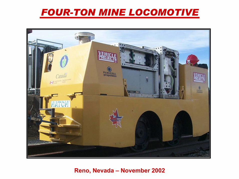
FOUR-TON MINE LOCOMOTIVE
Reno, Nevada – November 2002
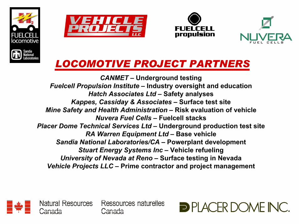
LOCOMOTIVE PROJECT PARTNERSCANMET – Underground testing
Fuelcell Propulsion Institute – Industry oversight and educationHatch Associates Ltd – Safety analyses
Kappes, Cassiday & Associates – Surface test siteMine Safety and Health Administration – Risk evaluation of vehicle
Nuvera Fuel Cells – Fuelcell stacksPlacer Dome Technical Services Ltd – Underground production test site
RA Warren Equipment Ltd – Base vehicleSandia National Laboratories/CA – Powerplant development
Stuart Energy Systems Inc – Vehicle refuelingUniversity of Nevada at Reno – Surface testing in Nevada
Vehicle Projects LLC – Prime contractor and project management
MINE-LOCOMOTIVE PROJECTOBJECTIVES
• Develop a zero-emissions, fuelcell-powered metal-mining locomotive.
• Evaluate its safety and performance, primarily in surface tests.
• Evaluate its productivity in an underground mine (Placer Dome) in Canada.

• No existing technology is clean, safe, and productive
— Tethered— Diesel— Battery
• Solution by fuelcells will provide cost offsets
— Lower recurring costs— Higher availability— Lower ventilation costs
A PROBLEM AND OPPORTUNITYUnderground Traction Power
LOCOMOTIVE PROJECT APPROACH
• Establish cross-functional project team including end-users• Use commercially available battery-powered 4-ton locomotive• Remove traction battery module and use existing electric drive• Design fuelcell powerplant and metal-hydride storage to fit into existing
battery compartment• Design metal-hydride storage module for easy removal from locomotive for
refueling on surface• Design fuelcell powerplant module for easy removal from locomotive for
transport to/from underground• Allow for onboard refueling as an option• Automate powerplant controls to allow for hands-free operation of
locomotive• Perform extensive safety and risk analysis to allow underground operation
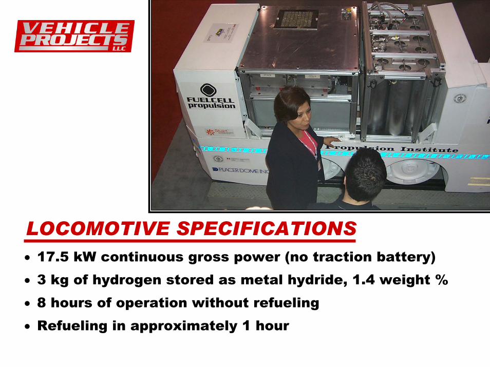
LOCOMOTIVE SPECIFICATIONS• 17.5 kW continuous gross power (no traction battery)• 3 kg of hydrogen stored as metal hydride, 1.4 weight %• 8 hours of operation without refueling• Refueling in approximately 1 hour

Comparison of Battery and Fuelcell 4-Ton Locomotives
Parameter Battery Fuelcell Power, rated continuous Current, rated continuous Voltage at continuous rating Energy capacity, electrical Operating time Recharge time Vehicle weight
7.1 kW (gross) 76 A 94 V (estimated) 43 kWh 6 h (available) 8 h (min) 3,600 kg
17.5 kW (gross) 135 A 129.6 V 53 kWh 8 h 1 h (max) 2,500 kg (without ballast)
Fuelcell energy capacity (available energy to the traction motor) is calculated as follows:2 g (1 mole) hydrogen = 286.6 KJ1 KJ = 0.000278 kWh3 kg = 3,000 g x 143.3 KJ/g x 0.000278 kWh/KJ = 119.5 kWhfuelcell stack efficiency = 50%parasitic loss = 1 kW = 6% lossenergy capacity = 119.5 kWh x 44% = 53 kWh
Note: The fuelcell locomotive used a commercial battery locomotive chassis and electric drive. Battery-vehicle parameters are those of the commercial product.

PEM FUELCELL SPECIFICATIONS
1.98Air stoichiometric ratio
80° CMaximum operating temperature
92Number of cells92 VOpen circuit voltage
25 LVolume25 x 18 x 55 cmDimensions30 kgWeight
Stack integralHumidifier
1.5 bar absoluteAir pressureAirOxidant gas1.7 bar absoluteHydrogen pressure99.995% pure hydrogenReluctant gas
135 ACurrent at rated power64.8 VVoltage at rated power8.75 kW continuousRated continuous power
NUVERA FUEL CELLS EUROPEPer Stack

MAJOR BENEFITS
• Health benefits of an electric vehicle coupled with the productivity of a diesel
• Reduced vehicle recurring costs
• Lower mine ventilation costs

FUELCELL POWERPLANT MODULES
HYDRIDE ENERGY STORAGEVertical cylinders safely store enough reversible metal-hydride material to
run the locomotive for 8 hours
FUELCELL POWER SYSTEMPEM fuelcell stacks (blue) provide 17.5 kW of continuous gross electrical power, over
twice that of the battery vehicle

SCHEMATIC DIAGRAM

Metals, crystalline solids, consist of a regular array or lattice of spherical atoms. Spheres cannot pack perfectly, and the lattice of atoms also forms a superimposed lattice of holes or interstices (see illustration). The interstices interconnect to form a 3-D network of channels.
In a metal hydride, hydrogen chemically bonds to the metal atoms while occupying the interstices. Ferrous metals form hydrides that are readily reversible and constitute a safe, solid storage medium for hydrogen. By removing low-temperature heat from the crystal, hydrogen atoms enter the interstices throughout the crystal and charge the metal. Conversely, by providing low-temperature heat to a charged crystal, the process is reversed and the metal is discharged. The gas pressure is approximately constant during the process and can be very low, even below atmospheric.
Unlike liquid or gaseous fuels, metal hydrides are of low flammability. This is because hydrogen is trapped in the metal matrix and the rate at which hydrogen atoms can file through the channels, recombine into hydrogen molecules, and be released is limited by the rate of heat transfer into the crystal. Rupture of a hydride system is self-limiting: As hydrogen escapes, the bed automatically cools and lowers the rate of escape. The metal matrix, moreover, forces the hydrogen atoms close together, as close as in liquid hydrogen, and is responsible for the high volumetric energy density.
Metal-Hydride Storage of Hydrogen
Crystal Lattice

OPERATION
• Mine safety and productivity have been established• Equal acceleration to battery version• More than twice the power• Ability to pull longer trains• Shorter recharge time• Longer operational time
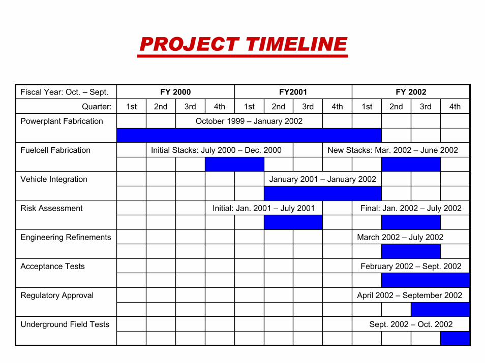
PROJECT TIMELINE
Sept. 2002 – Oct. 2002Underground Field Tests
April 2002 – September 2002Regulatory Approval
February 2002 – Sept. 2002Acceptance Tests
March 2002 – July 2002Engineering Refinements
Final: Jan. 2002 – July 2002Initial: Jan. 2001 – July 2001Risk Assessment
January 2001 – January 2002Vehicle Integration
New Stacks: Mar. 2002 – June 2002Initial Stacks: July 2000 – Dec. 2000Fuelcell Fabrication
October 1999 – January 2002Powerplant Fabrication
4th3rd2nd1st4th3rd2nd1st4th3rd2nd1stQuarter:
FY 2002FY2001FY 2000Fiscal Year: Oct. – Sept.

Underground Field TestsPlacer Dome Gold Mine, Balmertown, Ontario
• Two week test period• Locomotive put on production level 27 – 4,000 feet down• 760 tons of ore and rock moved• 30 hours actual operating time• 67,000 litres (~6 kg) of hydrogen consumed• No failures or downtime encountered• Metal-hydride bed transported to surface for refueling• Capable of longer operational shift than battery version

COST ANALYSIS
• 17.5 kW powerplant• 3 kg hydrogen, 213 kg metal hydride• Powerplant components cost – US $45,000• Hydrogen storage cost – US $35,000• Fuelcell stacks cost – US $90,000 (US $5,300 per kW)• Total powerplant cost per kW (with labor) – US $13,000
• To get the cost of PEM fuelcells below US $1,000 per kW, a cost reduction of 30% per year for 5 years would result in US $900 per kW
• With other cost reductions of 10% per year, total powerplant cost could approach US $5,400 per kW in 5 years
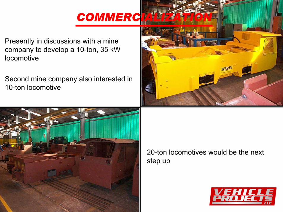
COMMERCIALIZATION
Presently in discussions with a mine company to develop a 10-ton, 35 kW locomotive
Second mine company also interested in 10-ton locomotive
20-ton locomotives would be the next step up