advances in finite element method for ship hydrodynamics · pdf fileadvances in finite element...
TRANSCRIPT

ADVANCES in FINITE ELEMENTADVANCES in FINITE ELEMENTMETHOD for SHIPMETHOD for SHIPHYDRODYNAMICSHYDRODYNAMICS
J. García-Espinosa, COMPASS ISJ. García-Espinosa, COMPASS [email protected]@compassis.com
FENET Technology WorkshopBarcelona, 27-28 Febrero 2003

ContentsContents
•• RANSE solver. Motivation.RANSE solver. Motivation.–– Finite Increment Calculus (FIC) formulationFinite Increment Calculus (FIC) formulation–– Implicit Fractional Step schemeImplicit Fractional Step scheme–– Monolithic Predictor-Corrector schemeMonolithic Predictor-Corrector scheme
•• Free surface solverFree surface solver•• Sink and Trim treatmentSink and Trim treatment•• Numerical and Implementation AspectsNumerical and Implementation Aspects•• Example: Example: RiojaRioja de de EspañaEspaña•• ConclusionsConclusions

RANSE solver. Motivation.RANSE solver. Motivation.
•• Implicit scheme: In most of the cases of interest for the navalImplicit scheme: In most of the cases of interest for the navalarchitecture the time step imposed by the stability criteriaarchitecture the time step imposed by the stability criteria(smallest elements) may be orders of magnitude smaller than(smallest elements) may be orders of magnitude smaller thanthe time step required to obtain time-accurate resultsthe time step required to obtain time-accurate results(physical time step), rendering explicit schemes impractical.(physical time step), rendering explicit schemes impractical.
•• Pressure-Velocity segregation: Monolithic schemes treatPressure-Velocity segregation: Monolithic schemes treatadvection term in an implicit manner, which avoids theadvection term in an implicit manner, which avoids thementioned disadvantages. Nevertheless, these methods arementioned disadvantages. Nevertheless, these methods arevery expensive from a computational point of view (velocityvery expensive from a computational point of view (velocityand pressure discrete equations are coupled).and pressure discrete equations are coupled).
•• Finite Increment Calculus: Stability of the numerical algorithmFinite Increment Calculus: Stability of the numerical algorithmis still today an open issue. There is a need for an accurate,is still today an open issue. There is a need for an accurate,pressure and advection stable algorithm, based on the physicspressure and advection stable algorithm, based on the physicsof the problem.of the problem.
Finite Increment Calculus (FIC) FoundationsFinite Increment Calculus (FIC) Foundations
0A Bq q− =A B
C
d1 d2
dx
qA qB
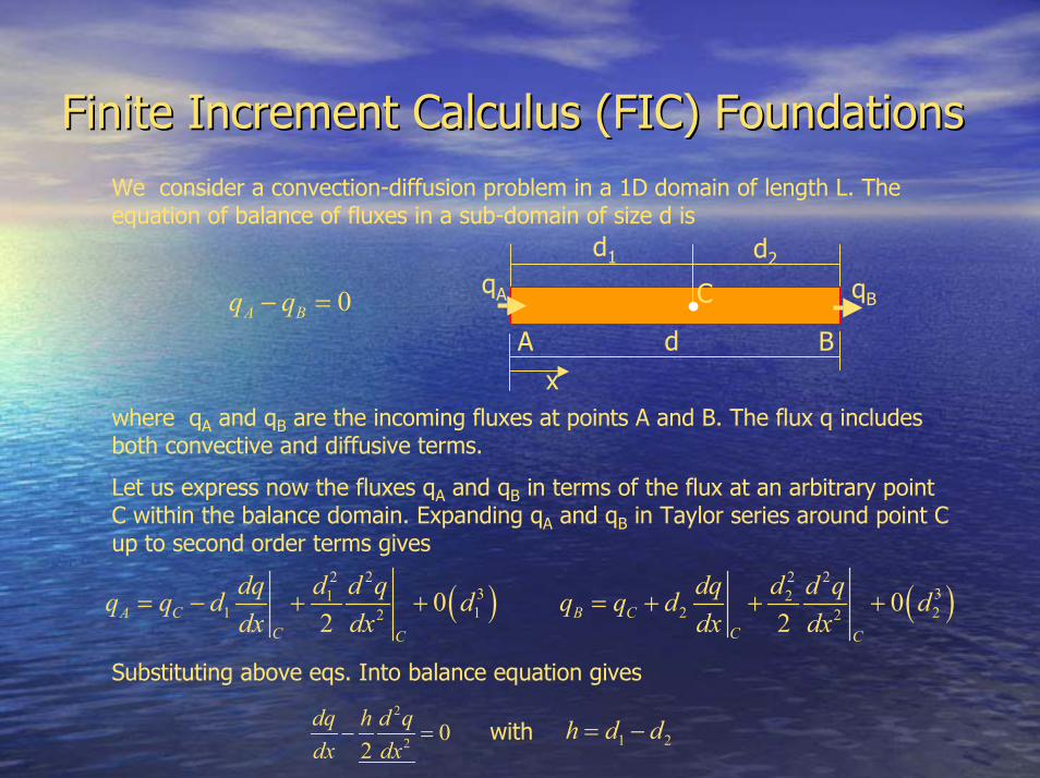
We consider a convection-diffusion problem in a 1D domain of length L. Theequation of balance of fluxes in a sub-domain of size d is
where qA and qB are the incoming fluxes at points A and B. The flux q includesboth convective and diffusive terms.
Let us express now the fluxes qA and qB in terms of the flux at an arbitrary pointC within the balance domain. Expanding qA and qB in Taylor series around point Cup to second order terms gives
( ) ( )2 2 2 2
3 31 21 1 2 22 20 0
2 2A C B CC CC C
dq d d q dq d d qq q d d q q d ddx dx dx dx
= − + + = + + +
Substituting above eqs. Into balance equation gives2
2 02
dq h d qdx dx
− = 1 2h d d= −with

Finite Increment Calculus (FIC) FormulationFinite Increment Calculus (FIC) Formulation
1 0 , 1,2,32
1 0 1,2,32
1 0 1,22
i
i
j
mm j
j
dd j
j
j
rr h on i j
x
rr h on jx
rr h on j
xβ
β β β
∂− = Ω =
∂
∂− = Ω =
∂
∂− = Γ =
∂
( )
1,2,3
1,2,3
i
ijim i j
j i j
id
i
ii
u pr u ut x x x
ur ix
r u it xβ
τ
β β
∂∂ ∂ ∂= + + −∂ ∂ ∂ ∂
∂= =∂
∂ ∂= + =∂ ∂
We consider the motion around abody of a viscous incompressible fluid(RANSE-NS) including a free surface(FS). The stabilized finite calculus(FIC) form of the governingdifferential equations for the threedimensional (3D) problem can bewritten as:
These eqs. are the starting point forderiving a variety of stabilizednumerical methods for solving theincompressible NS-RANSE equations.It can be shown, that a number ofstabilized methods allowing equalorder interpolations for velocity andpressure fields and stable andaccurate advection terms integrationcan be derived from this formulation

Implicit Fractional Step FormulationImplicit Fractional Step Formulation
( )1 1 0
2i
nnn n nmijn ni i
i j jj i j j
ru u pu u ht x x x x
θθθθ θ τ
δ
+++ ++ + ∂∂− ∂ ∂
+ + − − =∂ ∂ ∂ ∂
( )1 1 0
2i
nnn n nmijn ni i
i j jj i j j
ru u pu u ht x x x x
θθθ θ τ
δ
++++ + ∂∂− ∂ ∂
+ + − − =∂ ∂ ∂ ∂
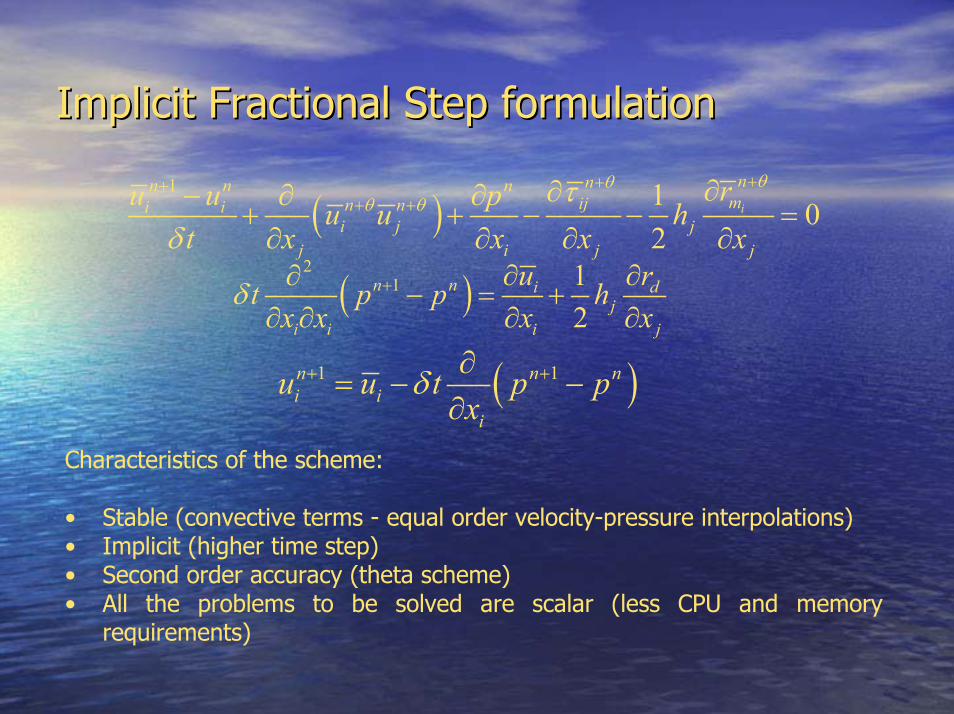
Discretization in time of the stabilized momentum equation using the trapezoidalrule (or θ method) as
An implicit fractional step method can be simply derived by splitting aboveequation as follows
( )1 1n n ni i
i
u u t p px
δ+ +∂= − −
∂This allow us to uncouple pressure and velocity calculations without loss ofaccuracy ( splitting errors of order 0(t2) )
( )2
1 12
n n i dj
i i i j
u rt p p hx x x x
δ + ∂ ∂∂− = +
∂ ∂ ∂ ∂
Implicit Fractional Step formulationImplicit Fractional Step formulation
( )1 1 0
2i
nnn n nmijn ni i
i j jj i j j
ru u pu u ht x x x x
θθθ θ τ
δ
++++ + ∂∂− ∂ ∂
+ + − − =∂ ∂ ∂ ∂
( )1 1n n ni i
i
u u t p px
δ+ +∂= − −
∂Characteristics of the scheme:
• Stable (convective terms - equal order velocity-pressure interpolations)• Implicit (higher time step)• Second order accuracy (theta scheme)• All the problems to be solved are scalar (less CPU and memory
requirements)
( )2
1 12
n n i dj
i i i j
u rt p p hx x x x
δ + ∂ ∂∂− = +
∂ ∂ ∂ ∂

Monolithic Predictor-Corrector schemeMonolithic Predictor-Corrector scheme
( ),, 11, 1 ,
, 1 , 1 1 02
i
n mn mn m n n mmijn m n mi i
i j jj i j j
ru u pu u ht x x x x
θθθθ θ τ
δ
++ ++ + ++ + + + ∂∂− ∂ ∂
+ + − − =∂ ∂ ∂ ∂
Characteristics of the scheme:
• Stable (convective terms - equal order velocity-pressure interpolations)• Implicit and monolithic (higher time step)• Second order accuracy (theta scheme)• All the problems to be solved are scalar (less CPU and memory
requirements)
( ), 1 ,2
, 1 , 12
i
n m n mn m n m d
ji i i j
u rt p p hx x x x
θ θθ θδ
+ + ++ + + ∂ ∂∂
− = +∂ ∂ ∂ ∂
All the arguments to derive Fractional Step scheme are still valid if we replacepressure term pn by any other pressure evaluation. In particular we may write(m iteration counter)

Free surface solverFree surface solver
1 0 1,22
1,2,3
jj
ii
rr h on j
x
r u it x
ββ β β
ββ β
∂− = Γ =
∂
∂ ∂= + =∂ ∂
FIC method can be directly applied to the free surface equation.
33
1j ij i i j jn n p n p n
R n Rγ γρτ ρτ− = ⇒ = −
Transpiration technique is used to couple free surface condition with RANSEsolver. This technique is based on imposing pressure at free surfaceobtained by stress continuity as (neglecting tangential components):
Being γ the surface tension coefficient and R the average curvature radius.Above condition is applied on a reference surface. FS eq. is also solved onthis reference surface not necessary being the exact free surface. In orderto improve accuracy of the solver a mesh updating procedure is applied.
Sink and Trim treatmentSink and Trim treatment
, yz
wp y
MFz gA gIαρ ρ∆ = ∆ =
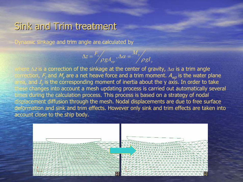
Dynamic sinkage and trim angle are calculated by
where ∆z is a correction of the sinkage at the center of gravity, ∆α is a trim anglecorrection, Fz and My are a net heave force and a trim moment. Awp is the water planearea, and Iy is the corresponding moment of inertia about the y axis. In order to takethese changes into account a mesh updating process is carried out automatically severaltimes during the calculation process. This process is based on a strategy of nodaldisplacement diffusion through the mesh. Nodal displacements are due to free surfacedeformation and sink and trim effects. However only sink and trim effects are taken intoaccount close to the ship body.

Final geometry updating and mesh regenerationFinal geometry updating and mesh regeneration
Finally a new calculation is performedwith the real geometry. This is done infour steps:•New free surface NURBS definition,taking the resulting deformation intoaccount, is generated:
• NURBS Cartesian support grid of MxNpoints is created.
• Z coordinate of the points,representing the wave elevation, isinterpolated into the grid.
• Finally, the NURBS surface based onthe support grid is generated.
•Geometry of the vessel if movedaccording to calculated sinkage andtrim angle.•New control volume and mesh areautomatically generated•New calculation is carried out withfixed mesh

Numerical and Implementation AspectsNumerical and Implementation Aspects
•• RANSE and FS equations are integrated by standardRANSE and FS equations are integrated by standardFinite Element Method (linear/quadratic tetrahedra,Finite Element Method (linear/quadratic tetrahedra,hexahedra, prisms, …)hexahedra, prisms, …)
•• RANSE and FS solvers have been optimized forRANSE and FS solvers have been optimized forworking with unstructured meshed of linearworking with unstructured meshed of lineartetrahedra/trianglestetrahedra/triangles
•• Implicit fractional step algorithm is used to go faster toImplicit fractional step algorithm is used to go faster tosteady statesteady state
•• Boundary conditions may be defined by analyticalBoundary conditions may be defined by analyticalfunctions allowing to run different drifts angles withfunctions allowing to run different drifts angles withthe same geometry/meshthe same geometry/mesh

Numerical and Implementation AspectsNumerical and Implementation Aspects•• RANSE-FS solver has beenRANSE-FS solver has been
implemented within the CFDimplemented within the CFDsystem Tdynsystem Tdyn
•• Tdyn includes a fully integratedTdyn includes a fully integratedpre/postprocessor based on GiDpre/postprocessor based on GiDsystem, incorporating advancedsystem, incorporating advancedCAD tools (NURBS importation,CAD tools (NURBS importation,creation and edition)creation and edition)
•• Data insertion (control volumeData insertion (control volumegeneration, physical properties,generation, physical properties,boundary conditions, etc) isboundary conditions, etc) isguided by the use of wizard toolsguided by the use of wizard tools
•• Mesh can be automaticallyMesh can be automaticallygenerated from the CADgenerated from the CADinformation within the system. Itinformation within the system. Italso allows elements sizealso allows elements sizeassignment and quality check ofassignment and quality check ofthe resulting meshthe resulting mesh
•• System also includes a set ofSystem also includes a set ofpostprocessing options and toolspostprocessing options and toolsfor report generationfor report generation

Application: Rioja de EspañaApplication: Rioja de España•• We present as example, theWe present as example, the
Spanish America’s Cup boatSpanish America’s Cup boatRioja de España, participantRioja de España, participantin the edition of 1995in the edition of 1995
•• Simulations have beenSimulations have beencarried out at full scale, usingcarried out at full scale, usinga a two layer k-e turbulencetwo layer k-e turbulencemodel, in combination withmodel, in combination withan extended law of the wallan extended law of the wall
•• Results are compared toResults are compared toexperimental dataexperimental dataextrapolations performed atextrapolations performed atEl Pardo towing tank with aEl Pardo towing tank with amodel at scale 1/3.5model at scale 1/3.5

ApplicationApplication: Rioja de España: Rioja de España
Acknowledgements: Authors thank National Institute of Aerospace Technique(INTA) for permitting the publication of the towing tank tests of Rioja de España,and the model basin El Pardo (CEHIPAR) for sending the full documentation of thetests. Special gratefulness to IZAR shipbuilders for allowing the publication of theRioja de España hull forms.

ApplicationApplication: Rioja de España: Rioja de España
2º2º25º25ºHull, bulb, keel andHull, bulb, keel andrudderrudderE25D2E25D2
4º4º15º15ºHull, bulb, keel andHull, bulb, keel andrudderrudderE15D4E15D4
2º2º15º15ºHull, bulb, keel andHull, bulb, keel andrudderrudderE15D2E15D2
0º0º0º0ºHull, bulb and keelHull, bulb and keelE0D0E0D0
0º0º0º0ºHull, no appendagesHull, no appendagesC0D0C0D0
Drift angleDrift angleHeel angleHeel angleGeometryGeometryTestTest
Every case was towed at equivalent velocities of 10, 9, 8.5, 8.0, 7.5 and 7.0 knots

ApplicationApplication: Rioja de España: Rioja de España
380 000380 0001 500 0001 500 000NoNoE25D2E25D2
380 000380 0001 500 0001 500 000NoNoE15D4E15D4
380 000380 0001 500 0001 500 000NoNoE15D2E15D2
175 000175 000700 000700 000YesYesE0D0E0D0
75 00075 000300 000300 000YesYesC0D0C0D0# Nodes# Nodes# Elements# ElementsSymmetrySymmetryTestTest
All grids used have been generated with the same quality criteria (in terms of sizetransition and minimum angle) and using element sizes from 5mm to 2000 mm.

All meshes have been generated with thesame quality criteria (in terms of sizetransition and minimum angle) and usingelement sizes from 5mm to 2000 mm.
Application: Application: RiojaRioja de de EspañaEspaña
E15D2 keel-bulbunion detail
Final meshE0D0
E25D2 Final Mesh
E15D2 Initialmesh

Application: Application: RiojaRioja de de EspañaEspañaE25D2 Streamlines and velocityE25D2 Streamlines and velocitymodulus contours (V = 9 Kn)modulus contours (V = 9 Kn)

Application: Rioja de EspañaApplication: Rioja de España
E25D2 Pressure, velocity andeddy viscosity contours
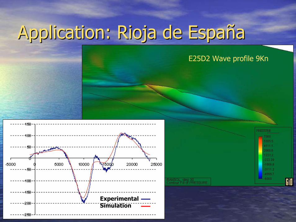
Application: Application: RiojaRioja de de EspañaEspañaE25D2 Wave profile 9Kn
ExperimentalSimulation

ApplicationApplication: Rioja de España: Rioja de EspañaE25D2 Wave profiles and pressure contours 9Kn

ApplicationApplication: Rioja de España: Rioja de EspañaE0D0 Pressure contours 10Kn

ApplicationApplication: Rioja de España: Rioja de EspañaE25D2 Pressure contours and streamlines 9Kn
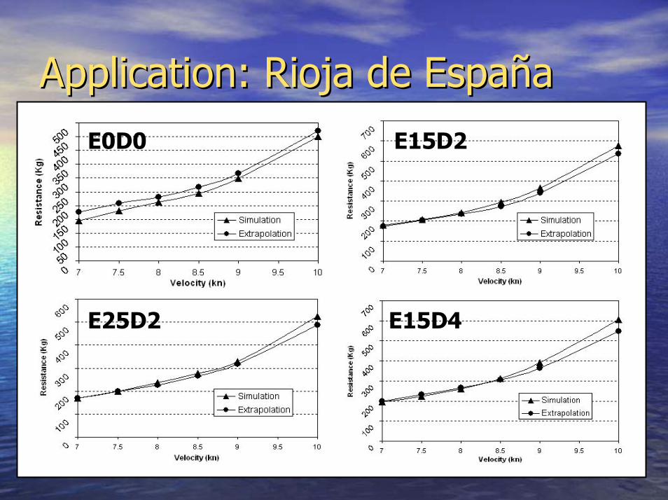
ApplicationApplication: Rioja de España: Rioja de EspañaE0D0 E15D2
E15D4E25D2

ConclusionsConclusions•• FIC technique applied to RANSE-FS equations allows to derive aFIC technique applied to RANSE-FS equations allows to derive a
number of stabilized schemes allowing equal-order velocity-pressurenumber of stabilized schemes allowing equal-order velocity-pressureinterpolation and adequate treatment of advection terms.interpolation and adequate treatment of advection terms.
•• An implicit second-order accurate monolithic scheme, based on the FICAn implicit second-order accurate monolithic scheme, based on the FICformulation has been derived to solve incompressible free surface flowformulation has been derived to solve incompressible free surface flowproblems. The final system of equations resulting from the time andproblems. The final system of equations resulting from the time andspace discretization is solved in each time step in an uncoupledspace discretization is solved in each time step in an uncoupledmanner.manner.
•• The numerical experience indicates that the formulation is very efficientThe numerical experience indicates that the formulation is very efficientfor free surfaces flows, when the critical time step of the problem isfor free surfaces flows, when the critical time step of the problem issome orders of magnitude smaller than the time step required to obtainsome orders of magnitude smaller than the time step required to obtaintime-accurate results - physical time step - (i.e. 4 CPU h / 1.5Mtetrastime-accurate results - physical time step - (i.e. 4 CPU h / 1.5Mtetrasstandard PC single processor, including standard PC single processor, including s&ts&t final calculation – adequate final calculation – adequatefor Grid Computing System “for Grid Computing System “ProcServerProcServer”).”).
•• Sink and trim effects as well as free surface deformations are takingSink and trim effects as well as free surface deformations are takinginto account in the solution process by automatic mesh updating and ainto account in the solution process by automatic mesh updating and afinal geometry and mesh regeneration.final geometry and mesh regeneration.
•• The solver has been optimized for using unstructured meshes of linearThe solver has been optimized for using unstructured meshes of lineartetrahedra, allowing a simple and automatic mesh generation fromtetrahedra, allowing a simple and automatic mesh generation fromcomplex NURBS based geometry, and the best mesh refinementcomplex NURBS based geometry, and the best mesh refinementcontrol.control.

ConclusionsConclusions•• RANSE-FS solver has been integrated within the pre/postprocessingRANSE-FS solver has been integrated within the pre/postprocessing
environment (GiD)environment (GiD)•• Graphical environment has been adapted to naval architectureGraphical environment has been adapted to naval architecture
needs by developing wizard toolsneeds by developing wizard tools•• Numerical results obtained in the analysis of America’s Cup Numerical results obtained in the analysis of America’s Cup Rioja deRioja de
EspañaEspaña and IMS AMC-CRC boats indicate that the proposed method and IMS AMC-CRC boats indicate that the proposed methodcan be used with confidence for practical design purposes.can be used with confidence for practical design purposes.–– Evaluation of total resistance gives less that 5% difference with towingEvaluation of total resistance gives less that 5% difference with towing
tank extrapolations in most part of the analysis range.tank extrapolations in most part of the analysis range.–– Evaluation of induced (lift) forces in non-symmetric cases gives evenEvaluation of induced (lift) forces in non-symmetric cases gives even
less differences.less differences.–– Obtained wave profiles are also very close to those measured in towingObtained wave profiles are also very close to those measured in towing
tank.tank.–– Dynamic sinkage and trim angles show similar behavior in bothDynamic sinkage and trim angles show similar behavior in both
experimental and numerical results. However, scale effects don’t allowexperimental and numerical results. However, scale effects don’t allowfurther conclusions.further conclusions.
–– Qualitative results including: wave maps, streamlines, pressure andQualitative results including: wave maps, streamlines, pressure andvelocity contours and turbulence distribution, show also reasonablevelocity contours and turbulence distribution, show also reasonablepatternspatterns

For further information ...For further information ...
http://www.compassis.com email:[email protected]://www.compassis.com/productos/en/tdyn/descargar