advancing test in coherent transmission systems
TRANSCRIPT

Advancing Test in Coherent Transmission Systems
Daniel van der Weide
1

Founded
– Sept 2007
CSLA 40G Product Launched
– March 2009
(OFC/NFOEC)
CSLA 100G
Product
Launched
–September 2009
First 10 Systems Sold
– January 2011
Acquired by Tektronix
-- July 2011
Optametra History
Complex Measurements Made Simple
2 Sept. 2011 55W-27383-0

Enables total calibration to make hardware “golden”
– Analog front end path gains, phase angles
– Frequency response
– Path delays (skew)
Removes laser frequency offset
Removes laser phase fluctuations
Presents resulting modulation field
– Constellation
– Eye Diagram
– Q plot
– EVM
Can also model receiver function and even impairments
– Remove CD, ISI, etc.; measure BER
– Emulate a delay-line interferometer for differential signaling
What does a Coherent Lightwave Signal Analyzer do?
3 Sept. 2011 55W-27383-0
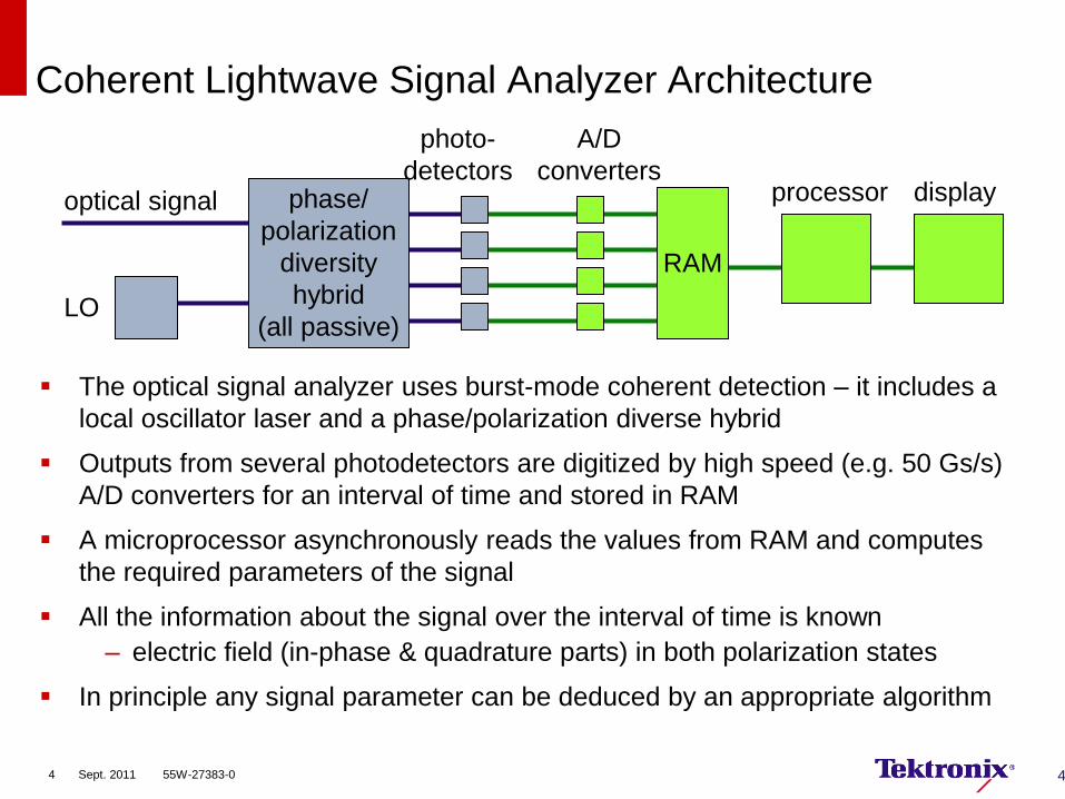
The optical signal analyzer uses burst-mode coherent detection – it includes a
local oscillator laser and a phase/polarization diverse hybrid
Outputs from several photodetectors are digitized by high speed (e.g. 50 Gs/s)
A/D converters for an interval of time and stored in RAM
A microprocessor asynchronously reads the values from RAM and computes
the required parameters of the signal
All the information about the signal over the interval of time is known
– electric field (in-phase & quadrature parts) in both polarization states
In principle any signal parameter can be deduced by an appropriate algorithm
Coherent Lightwave Signal Analyzer Architecture
4
LO
optical signal phase/
polarization
diversity
hybrid
(all passive)
photo-
detectors
A/D
converters
RAM
processor display
4 Sept. 2011 55W-27383-0

5
Advanced dual-polarization in-phase and quadrature
receiver with integrated signal and reference tunable
laser sources
Open-architecture MATLAB-based computational
engine offers powerful phase-recovery analyses with
polarization, bit-error rates, and record/playback
Graphical user interface controls frequently-used
instrument functions: − Laser control
− Modulation schemes
− PRBS or user-generated data
Works with all major real-time oscilloscopes
Easily upgradable
OM4000 Optical Modulation Analyzer Series
Complete and open solutions to complex measurement challenges in
long-haul fiber-optic communications
5 Sept. 2011 55W-27383-0

Understand and optimize optical networks employing advanced
modulation
– Measure constellation parameters, quadrature and modulator bias
values, symbol masks, EVM, signal and phase spectra, BER, Q vs.
decision threshold
– Save time, enable a wider range of users
Transition from R&D to qualification and production environments
– Enable automation
Test equalization and phase recovery algorithms
– CD, PMD, ISI
Understand effects of bandwidth limitations
– At the transmitter, digitizer, and receiver
Why do I need a Coherent Lightwave Signal Analyzer?
6 Sept. 2011 55W-27383-0
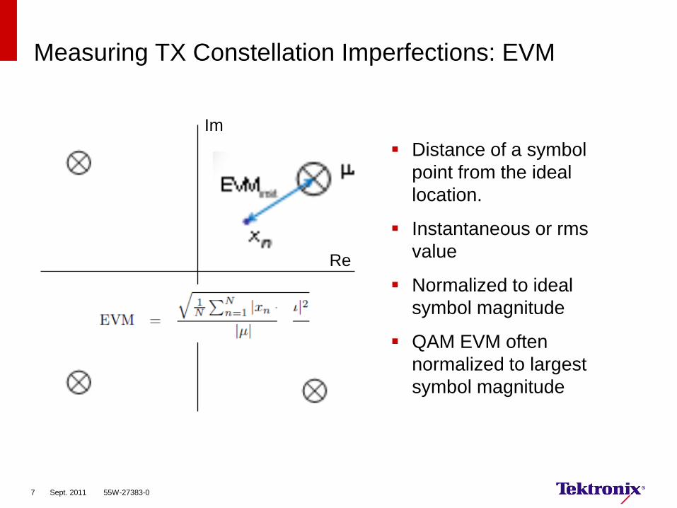
Measuring TX Constellation Imperfections: EVM
Distance of a symbol
point from the ideal
location.
Instantaneous or rms
value
Normalized to ideal
symbol magnitude
QAM EVM often
normalized to largest
symbol magnitude
Im
Re
7 Sept. 2011 55W-27383-0

Measuring TX Constellation Imperfections: Q-factor
Counts errors as
decision threshold is
moved.
Errors fitted to error
function in “Q-space”
→ Plot, max-Q and
optimum decision
threshold
Re
Im
8 Sept. 2011 55W-27383-0
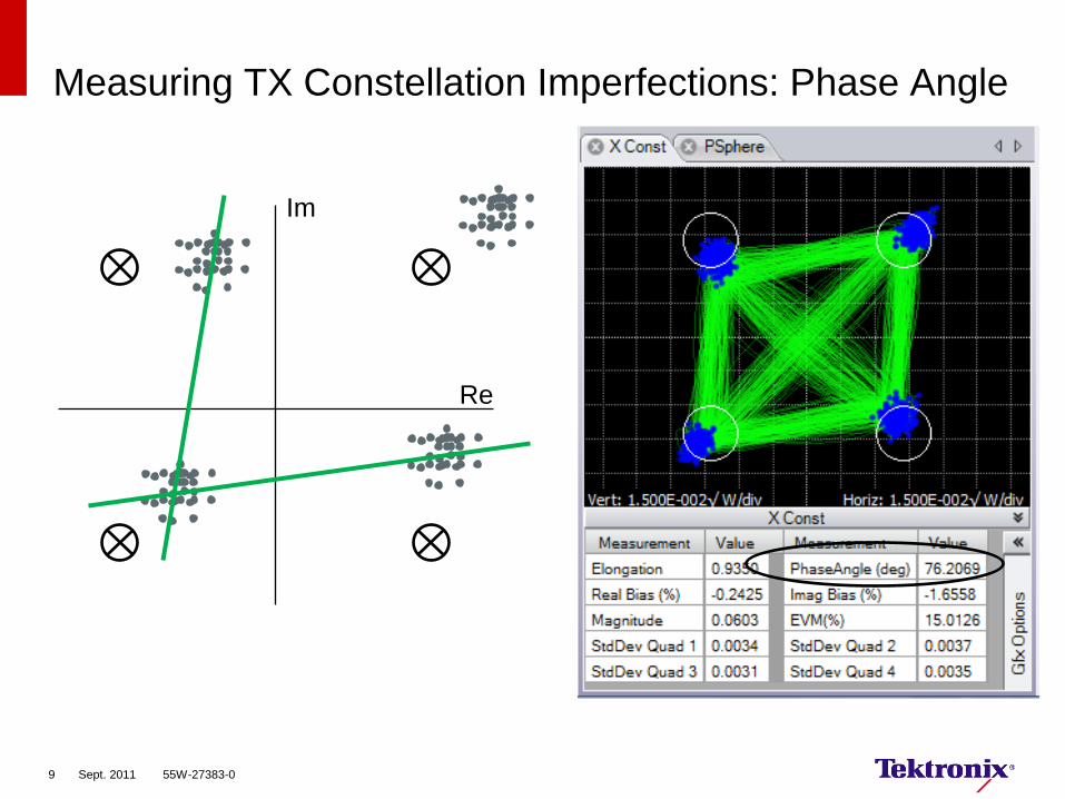
Measuring TX Constellation Imperfections: Phase Angle
Re
Im
9 Sept. 2011 55W-27383-0

Example: Modulator Bias Adjustment
10 Sept. 2011 55W-27383-0

Example: Adjusting Tributary Timing Skew
11 Sept. 2011 55W-27383-0

Measurements Available for QPSK Signals
12 Sept. 2011 55W-27383-0

Measurements Available for QAM Signals
13 Sept. 2011 55W-27383-0

20 G RZ DQPSK
14 Sept. 2011 55W-27383-0

One DC Module being Compensated. CD = 900 ps/nm
15 Sept. 2011 55W-27383-0
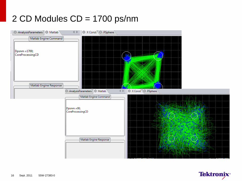
2 CD Modules CD = 1700 ps/nm
16 Sept. 2011 55W-27383-0

Acquisition
and Display
Loop
Filtering (cable compensation)
Core Processing (phase and clock recovery,
polarization resolution, resampling)
Display Formatted Data
Acquire Data
Pre-processing
(e.g .CD and PMD compensation can be done)
Data Acquisition and Processing Flow
17 Sept. 2011 55W-27383-0

Interaction Between GUI and MATLAB®
Write Analysis
Parameters to
MATLAB
Workspace
Acquire Scope
Record
Write Record to
MATLAB
Workspace
Clock Recovery
Polarization
Estimation
Phase Estimation
Ambiguity
Resolution
2nd Phase
Estimate
Count Bit Errors
Calculate
Constellation
Parameters
Plot Results –
Eyes, Constellation
Diagrams, Poincaré
Sphere
Report Bit Errors
Report Q-factors,
Constellation
Parameters
Matlab workspace SigType,
FreqWindow,
etc.
GUI
zXSym, zYSym, zX,
zY, DecTh, etc.
MATLAB GUI
Vblock
18 Sept. 2011 55W-27383-0

Flow Diagram (single pol case)
scope
record
ClockRetime
EstimateClock
ApplyPhase
EstimatePhase
ApplyPhase
EstimatePhase AlignTribs EstimateSOP
ClockRetime ApplyPhase
count bit errors
Q-factor
const params
symbol
center
E-field
continuous
E-field
scope sample rate symbol rate
N x symbol rate scope sample rate
19 Sept. 2011 55W-27383-0

Optametra Product Family
OM4000 Optical Modulation Analyzer Series
OM1106 Signal Analysis Software
– Optional hardware support
OM1206 Signal Analysis Test Set
– Software portion of the OM4106
– Includes tools for customer hybrid receiver calibration/ test
OM2010 Tunable Laser Source
– Provides additional laser sources
20 Sept. 2011 55W-27383-0

Bandwidth
Group delay variation
I-Q Crosstalk (hybrid phase angle error)
CMRR
Polarization crosstalk
Channel gain imbalance
Channel delay mismatch
RF mismatch effect on group delay
Frequency-domain crosstalk
Nonlinearity
Coherent Receiver Impairments
21 Sept. 2011 55W-27383-0

Coherent Receiver Testing
New OIF Agreement
IA OIF2009.033.06
Replace
input
signals with
reference
signals
Replace
ADC with
real-time
oscilloscope
Test overall:
•Path gains
•Cross talk
•Phase angles
At any frequency or wavelength
22 Sept. 2011 55W-27383-0

Sources of Polarization Crosstalk
LOY
LOX
Resulting LO
Moves with l and Temp
W ER/1W
Imperfect LO Laser Extinction
Imperfect Key or Splice
Alignment
PM-fiber-induced Rotation
Finite PBS Extinction Ratio
192 193 194 195 196-5
0
5
Laser Frequency (THz)
Measure
d R
ela
tive G
ain
(dB
)
Gain 1-2
Gain 3-4
Gain 1-3
Gain 1-4
23 Sept. 2011 55W-27383-0

Effect of pol-crosstalk on Phase Angle
LOSY ERERE
Re
Im
XE
XE
Apparent Ex is modified by
EY leakage
20 dB + 20dB: ±1.2°
15 dB +15dB: ±3.6°
Effect scales up if EY larger than Ex
LOSY ERERE
Re
Im
XE
XE
X-Inphase Output
X-Quadrature Output
24 Sept. 2011 55W-27383-0

Simple Hybrid Receiver Representation
SE
LOE
1
2
3
4
[a] [b]
[c] [d]
[e] [f] [g]
[h]
SE
p
p
p
p
V
V
V
V
4
3
2
1
4
3
2
1
ˆ
ˆ
ˆ
ˆ
4
3
2
1
1
V
V
V
V
H
E
E
E
E
Syi
Syr
Sxi
Sxr
SSLO EpEaEbRV 1
*
11ˆ
Syi
Syr
Sxi
Sxr
yyxx
yyxx
yyxx
yyxx
E
E
E
E
pppp
pppp
pppp
pppp
4444
3333
2222
1111
4
3
2
1
ˆImˆReˆImˆRe
ˆImˆReˆImˆRe
ˆImˆReˆImˆRe
ˆImˆReˆImˆRe
V
V
V
V
25 Sept. 2011 55W-27383-0

Optical Hybrid Calibration
EV H
VE1
H
Apply Ex or Ey, measure phase angle
− How to set Ex? Ey?
− What about crosstalk effect on
angle?
Or
Apply E1 and E2, find all hybrid
parameters
− E1·E2 = 0 (new coordinate system)
− Rotate back to hybrid system
Entire H is needed to find H-1
This gives full impact of finding E
given V
yi
yr
xi
xr
E
E
E
E
hhhh
hhhh
hhhh
hhhh
V
V
V
V
44434241
34333231
23232221
14131211
4
3
2
1
26 Sept. 2011 55W-27383-0

Hybrid Phase Angle, Gain, and Crosstalk
Excites RX under test with heterodyne signal
Two orthogonal polarizations
Computer takes data from scope and calculates hybrid parameters
Tunable laser permits full-band testing
LO Sig f2 f1
RX under test
Computer
191.5 192 192.5 193 193.5 194 194.5 195 195.5 196 196.5-35
-30
-25
-20
-15
-10
-5
0
5
Signal Frequency (THz)
Gain
, C
rossta
lk (
dB
)
192 193 194 195 196-5
0
5
Laser Frequency (THz)
Measure
d Q
uadra
ture
Phase E
rror
Phase 1-2-90deg
Phase 3-4+90deg
27 Sept. 2011 55W-27383-0

OM4106B
Receiver Testing Detail
Polarization
diverse
Coherent front-end
Real-time
Oscilloscope
10-90 Splitter
USB Optical
Power Meter
Computer
RX under
test
LO
Signal
Contr
olle
r Polarization
Switch
Laser
2
Laser
1
28 Sept. 2011 55W-27383-0

Co
ntr
olle
r
Polarization
Switch
OM4106B/ OM3105B-603 C-band Calibration Source and Software.
Includes 2 lasers. Use this option when C-band receiver has no
Optametra sources.
OM4106B/ OM3105B-604 L-band Calibration Source and Software.
Includes 2 lasers. Use this option when L-band receiver has no
Optametra sources.
OM4106B/ OM3105B-601 C-band Calibration Source and Software.
Includes 1 laser. Use this option when C-band receiver has an
Optametra Reference Laser.
OM4106B/ OM3105B-602 L-band Calibration Source and Software.
Includes 1 laser Use this option when L-band receiver has an
Optametra Reference Laser.
OM4106B/ OM3105B-600 Calibration Source and Software. Includes
no lasers. Use this option when receiver has 2 Optametra sources for
Reference and Signal.
Kit also includes optical power splitter and USB optical power meter
not shown. A real time sampling scope is required for calibration (not
provided).
Calibration Kit Options
La
se
r 1
La
se
r 2
Co
ntr
olle
r
Polarization
Switch
La
se
r 1
Co
ntr
olle
r
Polarization
Switch
29 Sept. 2011 55W-27383-0

Co
ntr
olle
r
Polarizatio
n Switch
OM4106B/ OM3105B-605 C or L-band Calibration Source and
Software. Includes 2 lasers combined to make a C+L source. Use this
option when receiver has a similar Optametra C+L Reference.
C+L Calibration Kit
L-L
ase
r
C-L
ase
r
L-L
ase
r
C-L
ase
r
Co
ntr
olle
r C+L
Optical
hybrid
RX RX
Real-time
Oscilloscope
C+L 10-90 Splitter
USB Optical Power
Meter
Computer
Typical Coherent Receiver Calibration test set up (below). Computer
and Real-time oscilloscope are not part of the kit. Receiver purchased
separately.
RX under
test
30 Sept. 2011 55W-27383-0

Coherent Lightwave Signal Analyzers can quantify quality of
transmitter signal
Optametra also offers tools for receiver characterization
Heterodyne analysis can be used to extract a simple hybrid matrix
describing the analog receiver front end
Measuring integrated receiver properties allows inclusion of optical
and electrical cross-talk effects
Conclusions
31 Sept. 2011 55W-27383-0