ae246 high pressure ptfe hose and “super gem”™ reusable
TRANSCRIPT

Aeroquip®
AE246 High Pressure PTFE Hose and “super gem”™ Reusable FittingsAssembly and disassembly instructions for hand and machine assembly
Table of Contents
Section I Introduction 1 1. Purpose 1 2. Scope — “super gem” Fittings 1 3. Description 1
Section II Identification 2-4 1. Identification and Construction of AE246 PTFE Hose 2 2. Fire Sleeve 2 3. Fittings - “super gem” Fittings 3 4. Hose Assemblies 3
Section III Disassembly 5
Section IV Cleaning 6
Section V Repair and Replacement 7 1. General 7 2. Fire Sleeved Hose Lines 7
Section VI Assembly Procedure — Hand Tool Method 8-11
Section VII Assembly Procedure — Machine Tool Method 12 1. General 12 2. Assembly of Fitting to Hose 12
Section VIII Proof Test Procedures 13 1. Equipment 13 2. Recommended Hydrostatic and Pneumatic Proof Test Pressures 13 3. Hydraulic Proof Test 13 4. Pneumatic Proof Test 13 5. Disposition If Fitting Leakage Is Noted 13 6. After Proof Test Operation 13
Section IX Removal of Hose Assemblies from Installation 14 1. Inspection 14 2. AN-MS Flared and Flareless Connections 14 3. Handling General 14
Section X Installation of Hose Assemblies 15-16 1. Installation, General 15 2. Routing and Clamping 15 3. Torque Values, Installations 16 4. “super gem” Fittings Used on Aeroquip AE246 Hose 16
Section XI Inspection Procedures 17-18 1. External Inspection of Hose Lines Removed from Service 17 2. Internal Inspection of Hose Lines Removed from Service 17 3. Hose End Fittings 17 4. Inspection of Component Parts 18
Section XII Permissible Rework 19 1. Hose Assemblies 19 2. Hose 19 3. Fittings 19 4. Fire Sleeves 19
Section XIII Storage of Hose and Hose Assemblies 20 1. Age Limitations 20 2. Bulk Hose 20 3. Hose Assemblies 20
Section XIV Disposition 20
Section XV Assembly Equipment, Special Tools, Fixtures and Service 21
EATON Aerospace Group TF100-63B October 2018 1
Section I Introduction
1. Purpose
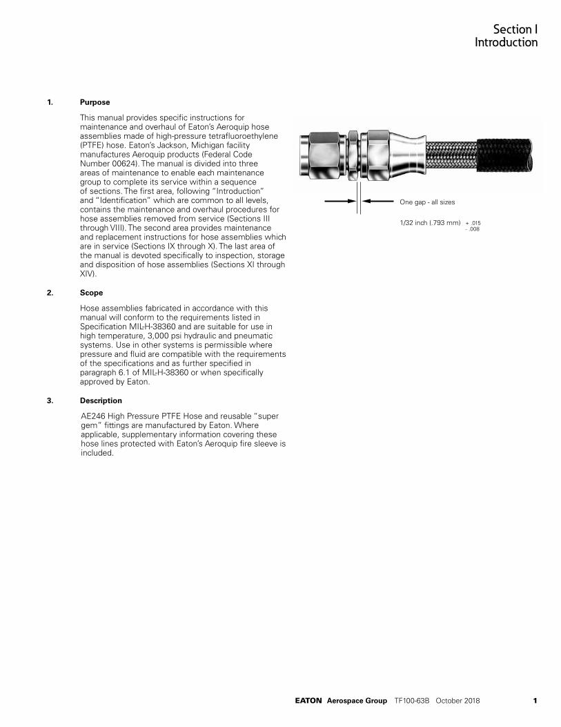
This manual provides specific instructions for maintenance and overhaul of Eaton’s Aeroquip hose assemblies made of high-pressure tetrafluoroethylene (PTFE) hose. Eaton’s Jackson, Michigan facility manufactures Aeroquip products (Federal Code Number 00624). The manual is divided into three areas of maintenance to enable each maintenance group to complete its service within a sequence of sections. The first area, following “Introduction” and “Identification” which are common to all levels, contains the maintenance and overhaul procedures for hose assemblies removed from service (Sections III through VIII). The second area provides maintenance and replacement instructions for hose assemblies which are in service (Sections IX through X). The last area of the manual is devoted specifically to inspection, storage and disposition of hose assemblies (Sections XI through XIV).
2. Scope
Hose assemblies fabricated in accordance with this manual will conform to the requirements listed in Specification MIL-H-38360 and are suitable for use in high temperature, 3,000 psi hydraulic and pneumatic systems. Use in other systems is permissible where pressure and fluid are compatible with the requirements of the specifications and as further specified in paragraph 6.1 of MIL-H-38360 or when specifically approved by Eaton.
3. Description
AE246 High Pressure PTFE Hose and reusable “super gem” fittings are manufactured by Eaton. Where applicable, supplementary information covering these hose lines protected with Eaton’s Aeroquip fire sleeve is included.
One gap - all sizes
1/32 inch (.793 mm) + .015- .008

2 EATON Aerospace Group TF100-63B October 2018
Section IIIdentification
Table I
General Specifications — Aeroquip AE246 PTFE Hose
Hose Size Tube SizeO. D. inches (mm)
OperatingPressurepsig (bar)
Min. BurstPressure psig (bar)
Min. BendRadiusinches (mm)
- 4 1/4 (6.35) 3000 (206.84) 16000 (1103.16) 1.50 (38.09)
- 6 3/8 (9.52) 3000 (206.84) 14000 (965.26) 2.50 (63.50)
- 8 1/2 (12.70) 3000 (206.84) 14000 (965.26) 2.88 (73.15)
- 10 5/8 (15.87) 3000 (206.84) 12000 (827.37) 3.25 (82.55)
- 12 3/4 (19.05) 3000 (206.84) 12000 (827.37) 3.88 (98.55)
1. Identification and Construction of AE246 High Pressure PTFE Hose
A. AE246 PTFE hose (Figure 1) conforming to the requirements of MIL-H-38360 has a corrosion resistant steel wire braid reinforcement covering an extruded PTFE inner tube. See Table 1.
B. Identification of AE246 PTFE Hose
1) Bulk hose Identification — Bulk hose has a tape with black letters specifying Aeroquip hose – size, operating pressure, lot number and hose manu-facturer’s code. Tape is located at each end and in middle of hose.
2) Hose Assembly Tag Identification — All factory assembled hose assemblies are identified with a metal band. Identification may include such information as customer part number, Federal Stock Number if required, hose assembly specification number, operating pressure in psig, manufacturer’s assembly part number, proof test symbol, date of assembly, and hose manufacturer’s Federal Code Number. See Figure 5.
2. Fire Sleeve
AE102/624 firesleeve is identified by a red silicone impregnated, braided asbestos sleeve having a black lay line with “Aeroquip AE102/624”– size repeated at 10 inch intervals.
3. Fittings
All component parts of fittings are impression-stamped with the part number.
Figure 1 - AE246 Bulk Hose
Figure 2 - Fire Sleeve
90º Adjustable Elbow 45º Adjustable Elbow
Figure 4. “super gem” elbow fittings
Figure 3. “super gem” fitting consists of 3 pieces: socket, sleeve and nipple assembly.
Sleeve Nipple Assembly Socket

EATON Aerospace Group TF100-63B October 2018 3
Figure 5. Identifying Metal Band
4. Hose Assemblies
All factory assembled hose lines are identified with a metal band (Figure 5) containing part numbers, date of assembly, etc. A detailed explanation of the different elements of a hose assembly part number is shown in Figure 6.
How To Complete Assembly Part Number
Basic types of hose assembly numbers are shown below. A detailed explanation of the different elements of the part numbers are given on these pages.
AE2460500 E 0184 Complete assembly number
(hose assembly with straight fittings or elbow on one end only)
Complete assembly number AE4108 E 0184 225
(hose assembly with elbow or special fitting on each end)
BASIC STYLE NUMBER Select hose required and choose correct assembly part number – basic style number – covering desired configuration. Use Aeroquip Aerospace Engineering Bulletin AEB 212 as a reference guide.
HOSE SIZE (letter code)
Hose size is expressed as a letter code which designates the tube O.D. in 1/16’s of an inch, for example, ½ - inch = -8 or letter code H. This code is added immediately following the basic style.
Hose dash size -4 -6 -8 -10 -12 Letter code E G H J K
Figure 6 - Assembly Part Number Explanation
Section IIIdentification

4 EATON Aerospace Group TF100-63B October 2018
Position Angle (Angle of Rotation)
For assemblies with an elbow fitting on each end, measure the position angle as shown and suffix the angle to the basic style number. The angle is expressed in three digits. For example: 35° would be written as 035. If the angle desired is 0°, specify as 000. The angle shown in the example is 225°.
Assembly Length
Assembly length is measured from sealing surface to sealing surface. On elbow fittings the measuring point is the intersec-tion of the centerline of the elbow with the face of the sealing surface. Assembly length will always be expressed in four digits. Last digit shall always indicate fractional length in 1/8’s of an inch. Thus, an assembly 18-1/2 long will be indicated as 0184.
Assembly Length Tolerances (PTFE Hose)
18 inches or less ± 1/8 inch
18 inches to 36 inches ± 1/4 inch
36 inches or longer ± 1% length
Adjustable elbow fittings are easily positioned through 360° to the desired relative angle between opposite elbow fittings. Mock-up and prototype installation changes are simplified as the position angle can be determined on the actual installation.
Bulk Hose
300 ft., AE246-8 Hose (random lengths)
300 pcs., AE246-8-0120 (specific lengths)
PTFE hose will be shipped in random lengths. If specific lengths are required, order as shown in the example above. An additional charge is made on orders for specific lengths.
Typical Straight Flareless Fitting Assembly
For complete configuration and style information, use Eaton Bulletin AEB 212 as a reference guide.
Section IIIdentification

Section III Disassembly
EATON Aerospace Group TF100-63B October 2018 5
Figure 8A. Removing Tube From Sleeve
1. Complete Assembly Tear-Down
Procedure for salvage of hose assembly components:
Step 1. (Fire-sleeved hose lines only). Remove band clamps by cutting clamp “buckles” with hack saw. Remove fire sleeve from hose assembly. (See Figure 7.)
Step 2. Place socket in vise and remove nipple assembly by applying wrench to nipple hex. (See Figure 8.)
Step 3. Cut hose approximately 1-inch from socket skirt.
Step 4. Hold socket firmly in vise. Do not damage socket. Using needle nose pliers, remove the tube from the sleeve and hose reinforcement. (See Figure 8A). The tube may be removed by folding longitudinally and pulling it out of the socket.
Step 5. With the socket still in the vise, separate the sleeve from the socket and hose reinforcement. The reinforcement can then be pulled out of the socket.
Step 6. Remove hose fitting from opposite end of assembly, using the same procedures, step 2 through step 5.
Step 7. Disposition of Component Parts — All hose shall be scrapped and component parts of fittings shall be inspected in accordance with inspection procedures. See Section XI.
Figure 8. Removing Nipple From Socket
Figure 7. Removing Fire Sleeve From Hose Assembly

Section IVCleaning
6 EATON Aerospace Group TF100-63B October 2018
1. General
It is recommended that all hose assemblies and component parts be thoroughly cleaned and degreased before inspection.
A. Cleaning Hose Assemblies with AE102/624 Fire Sleeve — It is suggested that the fire sleeve be completely removed before cleaning. When cleaning after proof test, installation of the fire sleeve should be the last operation performed.
B. Cleaning Hose Assemblies without Fire Sleeve — Flush hose assembly in cleaning fluid and brush, if necessary, to dislodge deposits. (For information covering F-2244 Hose Wash Stand, contact Eaton’s facility, Jackson, MI.
C. Cleaning Fitting Component Parts — Dip components parts and blow dry with clean air.
Caution: Do not wire brush parts.
D. Cleaning Fluids — The following fluids may be used for cleaning PTFE hose assemblies.
Caution: All dry filmed parts should be thoroughly dried after cleaning and before reuse.
E. Hose Assemblies After Proof Test — Flush hose assembly in cleaning fluid and blow dry with filtered air or dry nitrogen.
Table II
Fluids for Cleaning PTFE Hose Assemblies
Fluid Specification
Hose Assemblies:
Oleum Spirits Commercial
Kerosene P-S-661
Trichloroethylene MIL-T-7003 or OT634-A. Type II
*Synthetic Detergents MIL-D-16791
Fitting Components:
Trichloroethylene MIL-T-7003 or OT634-A. Type II

Section V Repair and Replacement
EATON Aerospace Group TF100-63B October 2018 7
Figure 9 - Removing Nut From Fitting
Figure 10 - Installation of Nut And Retaining Wire
Figure 11 - Setting Retaining Wire With Punch
1. General
Fittings with minor damage may be repaired and reused as follows:
A. Hose Assemblies — All hose assemblies with damaged hose shall have end fittings removed and salvaged and the hose scrapped.
B. Fittings (Nipple, Sleeve and Socket) —
(1) General — Replace all scrapped components.
(2) Damaged swivel nuts may be replaced as follows:
a. Cut nut down to retaining wire as shown in Figure 9.
b. Remove metal shavings and clean fitting.
c. Install new nut and drive in new retaining wire (Figure 10).
d. Set retaining wire with a punch (Figure 11).
Note: If nut does not turn freely after setting wire, it may be freed by tapping lightly with a hammer on the hex flats or tightening onto an AN815 adapter.
(3) Backed-out wires on wired-on nuts may be driven back into place and set with a punch (Figures 10 and 11).
2. Fire Sleeved Hose Lines
Remove fire sleeve as shown in Section III, Disassembly.
A. Replacement of Fire Sleeve — Lines requiring only replacement of fire sleeve may be repaired by replacing with a fire sleeve and clamp selected from Table III.
Note: Prior to assembling fire sleeve, the cut ends should be sealed with the compound as listed below in sub-section B, below.
B. Repair of Fire Sleeve
(1) Minor Abrasions and Scuffs — Cover with brush application of synthetic sealer Aeroquip AE13702-001 Sleeve End Dip Compound.
(2) Frayed Ends — Trim loose ends and brush or dip ends at least one-half inch into synthetic sealer.
Hose Dash Size Sleeve Part No. Clamp Part No.
-4 AE102/624-8 900591B1C
-6 AE102/624-11 900591B2C
-8 AE102/624-13 900591B2C
-10 AE102/624-14 900591B2C
-12 AE102/624-16 900519B2C
Table IIIFire Sleeve and Clamp Size Selector Chart

8 EATON Aerospace Group TF100-63B October 2018
Section VIAssembly Procedure — Hand Tool Method
1. General
The following steps should be followed when fabricating hose assemblies from new or salvaged components:
Note: Assembly mandrels are not needed for assembly of fittings using hand tool method.
Caution: Do not salvage used hose. Used hose is defined as hose which has been removed from an installation and returned for replacement.
A. Straight Swivel Fittings —
Step 1. Cut hose. Determine hose cut-off length by subtracting cut-off factors from Table IV from the desired hose assembly length. Cut hose squarely. A hose cut-off wheel is recommended. To prevent a flare-out of the wire end during the cut-off operation, several layers of tape should be wrapped around the hose at the cut-off point. After the hose is cut, and before proceeding with the assembly, the tape may be removed.
Caution: Hold hose firmly against angle plate or bolts of cut-off machine to bend hose at cutting point. It is recommended that the operator cut one sample and check length before proceeding with cutting the required quantity.
Figure 12. Cut-Off Factors
NOTE: Cut-off factors are for one end only (see Figure 12). Add cut-off factors for each end together and subtract from the desired hose assembly length to find the correct hose cut length.
37º Flared Fittings
Size Dim AST
Dim B45º
Dim C90º
-4 .92 (23.36) 2.06 (52.32 1.69 (42.92)
-6 1.04 (26.41) 2.35 (59.69) 1.92 (48.76)
-8 1.16 (29.46) 2.61 (66.29) 2.10 (53.33)
-10 1.21 (30.73) 2.74 (69.59) 2.06 (52.32)
-12 1.27 (32.25) 3.06 (77.72) 2.40 (60.95)
Flareless Fittings
Size Dim AST
Dim B45º
Dim C90º
-4 1.69 (42.92) 2.79 (70.86) 1.69 (42.92)
-6 1.80 (45.72) 3.13 (79.50) 1.92 (48.76)
-8 2.14 (54.69) 3.55 (90.16) 2.10 (53.33)
-10 2.35 (59.69) 3.83 (97.28) 2.06 (52.32)
-12 3.70 (93.98) 4.38 (111.25) 2.40 (60.95)
Table IV Hose Cut-Off Factors
Dimensions shown in inches (mm)

EATON Aerospace Group TF100-63B October 2018 9
Section VI Assembly Procedure — Hand Tool Method
Figure 13 - Placing Sockets On Hose
Figure 14 - Size Tube And Flare Braid
Figure 15 - Installation Of Sleeve
Step 2. Install sockets (size -4 through size -10). Place two sockets skirt-to-skirt in vise (see Figure 13), and work hose through sockets with a twisting pushing motion. Installing sockets over “neckdown” end of hose will facilitate assembly.
(Size -12 only) — Assemble sockets from each end of hose.
Note: If tape was left in place to ease socket assembly, it must be removed before additional steps are performed.
Step 3. Size tube and flare braid. Place nipple hex in vise. Push end of hose onto the nipple and work gently to aid in separating the wire braid from the tube. (See Figure 14.) Remove hose from nipple.
Step 4. Install sleeve. Carefully insert sleeve between braid and tube O.D. insuring that no wires are trapped between the sleeve and tube O.D. If the sleeve cannot be inserted over the tube, insert a neck down tool (see chart) over the end of the tube and push firmly. This will resize the tubing O.D. to accept the sleeve. Complete positioning by pushing end of sleeve against flat surface until tube bottoms against shoulder in sleeve I.D. (see Figure 15.) However, neck down tool may not be required for all sizes. Visually inspect to see that tube end is bottomed against sleeve shoulder and that no wires are trapped under sleeve.
Hose Size
Neck Down Tool
-4 S1272-2-1
-6 S1272-2-2
-8 S1272-2-3
-10 S1272-2-5
-12 S1272-2-7

10 EATON Aerospace Group TF100-63B October 2018
Section VIAssembly Procedure — Hand Tool Method
Step 5. Size tube to sleeve. Size tube to sleeve by pushing hose onto the nipple until the sleeve bottoms against the nipple chamfer. Remove and recheck to be certain that the sleeve is still properly positioned. Again push hose onto the nipple until the sleeve is bottomed against the nipple chamfer. (See Figure 16.)
Note: When assembling new fittings no lubrication is needed as component parts are dryfilm lubricated at the time of manufacture. After reuse of the fitting, if undue wearing of the dryfilm or bare metal is observed, the thread area should be lubricated with G N Paste. *
Step 6. (Size -4 through size -10) — Engage socket and tighten. Slide socket forward and thread onto nipple by hand. Remove assembly and place socket hex in vise. Using a wrench on the nipple hex, tighten to a gap of 1/32 inch nominal for all sizes. (Gap may vary from 0.023 to 0.046 inch.)
(Size -12 only) — Socket must be preseated prior to thread engagement. With the socket held firmly in a vise, insert socket preseat hand tool (S1272-8-1), into the hose. Using a nonfer-rous hammer, tap the preseating tool forcing the sleeve into the socket until the threaded end of the socket bottoms against the shoulder on the preseating tool. (See Figure 18.)
Step 7. Install opposite hose fitting in the same manner.
Caution: If both fittings are elbow fittings, the relative position angle (index angle between fittings) must be set before tightening to final gap, see B, elbow fittings.
*G N Paste is a product of the Dow Corning Corporation.
Figure 16. Sizing Tube to Sleeve
Figure 17. Engaging Socket to Nipple
Figure 18. Preseating Socket on Size -12

EATON Aerospace Group TF100-63B October 2018 11
Section VI Assembly Procedure — Hand Tool Method
Step 8. Proof test hose assembly as described in Section VIII, Proof Test Procedures.
Step 9. Marking — After proof test, all bulk hose manufacturer’s code identification bands shall be removed and the hose assembly identified with a metal band containing the information listed in Section II, paragraph 1.B.2, plus a symbol to identify base or facility where hose assembly was made.
B. Elbow Fittings — Method to establish the proper position angle of fittings when an elbow fitting is used on both ends.
(1) Method for ”standard” elbow fittings
Step 1. Assemble one end as described previously in paragraph 1A, page 8 for assembly of straight swivel fittings.
Step 2. Assemble the opposite end as described in paragraph 1A, except do not tighten socket to the specified gap. Leave nipple loose enough to swivel by hand.
Step 3. Establish base position. Base position (or zero degrees) may be the top of a work bench or an elbow mounted in a vise with the nut pointed down.
Figure 19. Reading Position Angle
Step 4. Position and measure position angle. See Figure 19, below, for proper reading of posi-tion angle. While opposite fitting is still loose enough to swivel by hand, turn to required angle and measure, using a similar complete hose assembly or an adjustable protractor or other suitable angle-measuring device.
Step 5. Complete fitting assembly by mounting the socket in a vise. Hold elbow from turning while tightening the elbow union to the required gap.
Note: Setting the angle may be facilitated by first tightening to near maximum gap, then back-off, set elbow to required angle and tighten to prescribed gap while holding elbow in position.
Step 6. Recheck position angle to be sure position angle has not changed.

12 EATON Aerospace Group TF100-63B October 2018
Section VIIAssembly Procedure — Machine Tool Method
1. General
The following approved equipment is recommended for production assembly of the hose assemblies covered by this manual:
Machine equipment should be selected according to the individual need of the particular operator.
2. Assembly Of Fitting To Hose
Step1. The general procedure described in Section VI, Assembly Procedures — Hand Tool Method, shall be followed. In addition, the following supplemental instructions will apply when using machine equipment for assembly. Specific instructions for operation, use, and maintenance of the equipment are included in the appropriate handbook for the particular type of equipment.
Step 2. Sleeve preseating, socket preseating, and tube neck down can be accomplished by machine when using the following tools:
Hose Size
Sleeve Preseating Tool
Socket Preseating Mandrel
Neck Down Tool
-4 S1272-7-1 S1272-3-1 F2717-6-7
-6 S1272-7-2 S1272-3-2 Not Required
-8 S1272-7-3 S1272-3-3 Not Required
-10 S1272-7-4 S1272-3-5 Not Required
-12 S1272-7-5 S1272-3-7 Not Required
Step 3. Select proper mandrel for the machine being used.
Step 4. Adjust jaws on the machine head to provide slip clearance on the nipple hex. This clearance should be approximately .010 inch (.254 mm).
Step 5. Insert hose with socket in carriage and clamp securely. Insert nipple assembly in head.
Step 6. Allow machine to screw the nipple into the socket to the prescribed gap: 0.023 to 0.046 inch (.584 to 1.168 mm).
Part No. Name
S1022 Hose Cut-Off Machine, Bench Mounted
S1229 Hose Cut-Off Machine, Bench Mounted
F2152 Hose Assembly Machine
F2197 Hose Proof Test Stand

Section VIIIProof Testing Procedures
EATON Aerospace Group TF100-63B October 2018
Section VIIIProof Testing Procedures
1. Equipment
The following equipment is recommended for proof test of hose assemblies covered by this manual.
Eaton Part No. Name
F2197 Hydraulic Proof Test Stand
For information covering pneumatic proof test equipment, contact Eaton.
2. Recommended Hydrostatic and Pneumatic Proof Test Pressures
A. The recommended hydrostatic proof test pressure is 6,000 psi (413.68 bar) for all sizes.
B. The recommended pneumatic proof test pressure is 3,000 psi (206.84 bar) for all sizes.
3. Hydraulic Proof Test
Proof test medium shall be hydraulic oil, Specification MIL-H-5606 or water. All hose assemblies shall be proof tested after assembly for a period of not less than 30 seconds and not more than 5 minutes.
Note: Proof test stands and special adapters are avail-able from Eaton to facilitate testing large quantities of hose assemblies. See Assembly Equipment, Special Tools, Fixtures, and Services, Section XV.
4. Pneumatic test
Pressure test air-under-water for not less than 30 sec-onds nor more than 5 minutes and observe for bubbles indicating leakage.
Warning: Pneumatic leakage testing shall only be performed under a protective cover for the safety of the operator.
Caution: Never proof test sleeved hose lines under water.
5. Disposition If Fitting Leakage Is Noted
A. Remove hose assembly and check for proper gap (Section VI – Assembly Procedure.)
B. If proper gap was obtained, disassemble hose assembly according to Section III – Disassembly. Inspect fittings as described in Section XI.
6. After Proof Test Operation
A. Cleaning — Clean and drain assembly after proof test. See Cleaning, Section IV.
Note: Application of an identifying mark such as a paint dot, etc., indicating satisfactory proof test is recommended.
B. Capping — Cap or plug all hose assemblies to ensure cleanliness.

Section IXRemoval of Hose Assemblies from Installation
14 EATON Aerospace Group TF100-63 October 2011
1. Inspection
Inspection and replacement of PTFE hose assemblies should be accomplished at specified maintenance or overhaul periods for the aircraft or engine as prescribed by applicable aircraft inspection requirements, or whenever leakage, abrasion of the cover, kinks or other mutilation is evident.
2. AN-MS Flared And Flareless Connections
Apply one wrench to the swivel nut (also called “B” nut) and second wrench to hex on nipple portion of hose fitting. Turn nut to loosen and remove hose line. (See Figure 20.)
Caution: Do not place wrench on socket of hose fitting when removing hose line (See Figure 21).
3. Handling General
PTFE hose assemblies will tend to preform themselves (assume their installed shape) to the installed position on hot fluid lines. For this reason, care should be exercised in handling and removing these lines from installation. Sharp or excessive bending will tend to kink PTFE hoses.
Caution: Do not bend or attempt to straighten pre-formed PTFE hose lines.
Warning: Do not stand on hose lines or use lines for a handle.
Figure 20. Loosening Swivel Nut
Figure 21. Wrong Method To Loosen Swivel Nut

Section XInstallation of Hose Assemblies
EATON Aerospace Group TF100-63B October 2018 15
Figure 22. Routing and Clamping of Hose Lines
1. Installation, General
Extra care should be exercised to avoid kinking as a result of sharp bending or twisting.
Caution: Kinking occurs more easily in larger size hose and in very short hose lines. Use care in handling and installing all PTFE lines.
Note: Wires and clamps used to hold pre-formed shapes should be removed at time of installation.
2. Routing And Clamping
All hose lines must be carefully routed and securely clamped to avoid abrasion and particu-larly to prevent kinking on flexing installations. Figure 22 illustrates routing and clamping of hose lines.
A. Protection Against Abrasion — Eliminate chafing against structure, moving parts of other lines by proper clamping and by use of chafing guard on unsleeved hose assemblies (Aeroquip 656 PTFE Guard or 646 Neoprene Chafe Guard), if necessary.
B. Hose Line Support — Support hose at least every 24 inches. Closer supports are preferred. Flexible liens should be supported so that they will not cause deflection of rigid connecting lines. Hose lines between two rigid connections may have excessive motion restrained where necessary but should never be rigidly supported. Support clamps shall not restrict travel or cause hose to be subjected to tension, torsion, compression or shear stress during flexing cycles. Select proper size support clamp from Table VI.
Hose Dash Size -4 -6 -8 -10 -12
High Pressure AE246 MS21919- 6 8 10 12 14
High Pressure AE246 with AE102 Fire Sleeve
MS21919- 11 14 16 17 19
Note: Appropriate clamp cushion material to be determined by application conditions.
Table VI
Cushion support clamp sizes (for use with Aeroquip AE256 hose)

Section XInstallation of Hose Assemblies
16 EATON Aerospace Group TF100-63B October 2018
C. Installation with Bending — When bends are required, the radii shown in Figure 23 should be maintained for normal installation with no flexing. A larger radius than the minimum allowed is preferred.
D. Flexing Installations — The following precautions will help prevent kinking:
(1) Hose should be bent in same plane as movement to avoid twisting. See Figure 24.
(2) Hose flexing in two directions should be clamped at the point where the hose changes planes. (This has effect of dividing hose into sections, each in one plane.) See Figure 24.
3. Torque Values, Installation
Swivel Connections — Install flared and Aeroquip Globeseal flareless swivel connections using position-tightening procedure as follows:
Step 1. Locate assembly in desired position and then turn nut finger tight.
Step 2. While restraining nipple hex with one wrench, tighten nut to the appropriate torque value in Table VII. Do not overtighten.
Step 3. If connection leaks during pressure check, loosen and completely disconnect the nut. Inspect the fitting for damaged sealing surfaces, present of foreign material or damage from previous overtightening.
Figure 23. Minimum Bend Radius. Figure 24. Flexing Installations.
Fitting Size
Torque in. - lbs.
Steel
Min. Max.
-4 135 145
-6 215 245
-8 430 470
-10 620 680
-12 855 945
Hose Size
Recommended Min. Bend Radius inches (mm)
-4 1.50
-6 2.50
-8 2.88
-10 3.25
-10 3.88
Installation Torque Values, Flared and Globeseal Flareless Swivel Fittings
4. Fittings Used On Aeroquip AE246 Hose
In addition to the above general procedures, the following caution should be observed.
Caution: Do not place wrench on socket of hose fitting when installing hose lines.
Table VII

EATON Aerospace Group TF100-63B October 2018 17
Section XIInspection Procedures
EATON Aerospace Group TF100-63A March 2013 17
1. External Inspection of Hose Lines Removed From Service
All hose assemblies should be inspected to determine if the assembly can be returned to service, repaired, or if it must be replaced.
A. Unsleeved Hose Lines — Thoroughly examine hose externally for evidence of twisting, kinking, abrasion and broken wires.
(1) Abrasion and Broken Wires — If excessive wire breakage, either general or localized as a result of abrasion, etc., is found, the hose assembly shall be rejected and the fittings salvaged.
Note: The following is offered as a rule-of-thumb measure — If two (2) or more broken wires per plait or more than six (6) broken wires per lineal foot are found, or any broken wire in a position where kinking is suspected, the hose should be scrapped. Crossed-over reinforcement wires shall not be cause for scrapping.
(2) Hydraulic Pressure Lines — Hydraulic hose lines which are found to have broken wires shall be scrapped and the fitting salvaged.
(3) Kinking — Any hose assembly show-ing evidence of dents, kinks or twist-ing should be scrapped.
B. Fire Sleeved Hose Lines
(1) Fuel or oil soaked fire sleeve shall be scrapped.
(2) Severely abraded or mutilated fire sleeve shall be scrapped.
(3) Slight abrasion or frayed ends may be repaired and returned to stock. See Section V – Repair and Replacement.
(4) Undamaged fire sleeve may be returned to stock.
2. Internal Inspection Of Hose Lines Removed From Service
A. Restrictions — Carefully examine hose inter-nally for restriction, tube collapse or other signs of hose damage.
B. Inspection Procedures — The following internal inspection procedures are recommended:
(1) Straight Hose Assemblies — Hose ID can be checked by looking through hose at a light source.
(2) Elbow Fitting on One End — Insert flexible inspection light into one end and examine from straight-fitting end.
(3) Elbow Fittings on Both Ends — Insert flexible inspection light into one end and examine from opposite end with dental-type mirror. This procedure is only practical on larger size hose assemblies.
(4) Other Configurations and Small Size Hose — Pass a ball of proper size (select from Table VIII) through the hose assembly to check for restrictions.
Note: These are standard master ball sizes.
3. Hose End Fittings
A. General — Examine end fittings for nicks, dents in bent tube portion, or other damage which would impair sealing under pressure or hose retention characteristics of the fitting. If any damage is evident upon visual inspection as described below, the hose assembly shall be disassembled and individual component fittings salvaged. See Disassembly procedure, Section III.
B. Swivel Connections — Examine swivel connections as follows:
(1) Check for mutilated threads and evidence of overtightening. This will show up as a belled condition or “pulled” condition on flared connections, and may result in a frozen or tight swiveling nut. Damaged wired-on swivel nuts may be replaced. See Section V, Repair and Replacement.
(2) Examine for backed-out retaining wires on wired on swivel nuts. Drive wire back into nut. See Section V, Repair and Replacement.
(3) Visually inspect sealing surfaces of nipples for nicks, spiral or longitudinal scratches or scoring which could create an escape passage for fluids. Check for flare-out or distortion of cone seats resulting from overtorque.
(4) All swivel fittings with damaged sealing surfaces shall be scrapped.
AE246 Hose Dash Size
Ball Size (Inches)
-4 1/8
-6 15/64
-8 21/64
-10 27/64
-12 17/32

18 EATON Aerospace Group TF100-63B October 2018
Section XIInspection Procedures
4. Inspection Of Component Parts
A. General — All fitting components should be examined for corrosion damage. It is recommended that corrosion-damaged parts be scrapped. Minor scratches are not cause for replacement.
B. Socket — Visually check for distortion or “egging” of socket and also test for damaged threads by threading a new nipple assembly of proper size into the socket threads. Damaged sockets shall be scrapped.
C. Nipples
(1) Visually inspect the sealing surface of nipples (see Figure 25) for damage or galling and condition of dry film lubricant.
(2) Visually check for galled threads (nipple to socket thread) and test by threading a new socket of proper size onto the nipple threads.
(3) Test for overtorque by placing a new sleeve on the nipple in the normal assembled position. Check for clear-ance between the sleeve and nipple faces. See Figure 26.
(4) Visually inspect wrench flats on forged-type elbow nipple assemblies for excessive wrench marks.
(5) Scrap damaged nipples or nipples with no clearance. See Figure 26.
Figure 25Sealing Surface of Nipples
Figure 26Nipple Assembly
Figure 27Sleeve
D. Hose — All hose removed from hose assemblies shall be scrapped.
E. Nut and/or Male Nipples
(1) Visually inspect nut internal threads and threads on male nipple assemblies. Acceptable threads will have at least 50% of entrance thread intact, provided balance of threads are not defective. Damage to balance of threads shall not exceed 25% of one thread, provided entrance thread is not damaged. All threads shall also fall within the pitch diameter tolerances of class 2, Military Specification MIL-S-8879, to be acceptable.
(2) Disposition — All damaged threaded components, except as described above, shall be scrapped. Wired-on swivel nuts may be replaced. See Figures 9, 10 and 11.
F. Sleeve
(1) Check the sealing surface (see Figure 27) for nicks, scratches or galling.
(2) Visually inspect gripping surface (sloping OD, Figure 27) for severe brinelling from hose braid, crimping or obvious out-of-round condition.
(3) Disposition — Damaged sleeves shall be scrapped.

Section XIIPermissible Rework
EATON Aerospace Group TF100-63A March 2013 19
1. Hose Assemblies
A. Hose assemblies may be shortened (new assemblies only) by removal of one end fitting.
B. On fire sleeved assemblies, it may also be necessary to shorten the fire sleeve.
C. Disassembly of the end fitting shall be in accordance with Section III.
D. Cut hose to the desired length.
E. Assembly of the end fitting shall be in accordance with Section VI.
2. Hose
A. None (except length may be cut as described in 1A above).
3. Fittings
A. Rework of fittings is restricted to the replacement of damaged swivel “B” nuts.
B. Swivel “B” nuts will be replaced in accordance with Section V, paragraph 1.B.
C. Dry Film — Inspect threads and sealing surfaces for wear. If undue wearing of the dry film is observed or bare metal is revealed, the entire thread and/or sealing surface may be evenly lubricated with G N Paste*. Lubrication should be performed after cleaning just prior to assembly.
Note: G N Paste should not be thinned.
4. Fire Sleeves
Fire sleeves may be repaired as outlined in Section V, paragraph 2.
* G N Paste is a product of the Dow Corning Corporation

20 EATON Aerospace Group TF100-63A March 2013
Section XIIIStorage of Hose and Hose Assemblies
1. General
All hose, fittings, or hose assemblies which are scrapped or are otherwise unsatisfactory for use on aircraft, missiles, and related accessories, shall be condemned in accordance with applicable regulations.
Section XIVDisposition
1. Age Limitations
No age limitations have been established on high-pressure tetrafluoroethylene hose.
2. Bulk Hose
Cut ends of hose should be taped closed to prevent wire flare-out and keep out dirt. Storage in a straight position is preferred. If coiling is necessary, large, loose coils are preferred.
Caution: Under no circumstances shall hose be piled to a height which could result in damage to the under sec-tions. This caution applies to hose in cartons as well as unpackaged hose.
3. Hose Assemblies
All hose assemblies should have ends capped or plugged during storage with plugs conforming to Specification MIL-C-5501 (ASG), or other applicable plastic or metal plugs.

EATON Aerospace Group TF100-63A March 2013 21
Section XVAssembly Equipment, Special Tools,
Fixtures and Services
1. General
Many special tools and equipment have been designed by Eaton to facilitate the assembly, proof testing, clean-ing, etc. of PTFE hose. These include special tool and power equipment for both small volume and production-type shops. Service engineering assistance is available for shops or engineering groups relative to either equip-ment or hose assembly installation. For a copy of Eaton product brochures, or to obtain engineering assistance, contact Eaton Aerospace Group, Conveyance Systems Division, 300 South East Avenue, Jackson, Michigan 49203.

Copyright © 2018 EatonAll Rights ReservedForm No. TF100-61C(Supersedes ASB116ROctober 2018
Eaton Aerospace Group Fluid & Electrical Distribution Division 300 South East Avenue Jackson, Michigan 49203-1972 Phone: (517) 787 8121 Fax: (517) 789 2947
EatonAerospace Group9650 Jeronimo RoadIrvine, California 92618Ph (949) 452 9500Fax (949) 452 9555www.eaton.com/aerospace