aeg low voltage component - mindco.com.cn · epoxide resin casting dry-type transformer - in 1976,...
TRANSCRIPT
Technology transfers reliable power
AEG Low Voltage Component

● History of establishment and innovation- In 1883, Mr. Rathenau established the AEG company to
produce l ight bulbs in Berlin, Germany. Soon, the company began to produce low-voltage electrical devices and transmission & distribution products, which had first accelerated the global progress of electrical development with GE and Siemens at that time.
- in 1935, AEG has produced the first free jet air circuit breaker in the world
- in 1964, AEG has produced the first 400kVA/ 20kV epoxide resin casting dry-type transformer
- in 1976, AEG has developed the first patent eccentric epicyclic gear drive system which was applied to the performer successfully.
● Long history with China- In 1928, Zuobing Jiang, the Chinese ambassador and his
accompanies visited AEG factories.- In 1980, by means of technology transfer, Shanghai
Renmin electrical appliance factory produced ME series low-voltage air circuit breakers, which became the pioneer products in Chinese market in the 1980’ s and early 1990’ s.
- In 1981, by means of technology transfer, Shanghai electric appliance ceramics factory produced NT filling package confined fuses, which are still popular products in Chinese market.
● Commercial life- In 1996, General Electric (GE) has acquired AEG’ s
low-voltage services, and thus AEG has become the main technological basis for GE Europe and global IEC market. The AEG brand products cover heavy manufacturing industries including steel, shipping, railway, aerospace, etc. The AEG is still working for customers in some traditional markets such as Germany, Belgium, Hispanic, etc.
● AEG is coming back to China- In 2009, the AEG came back to China and has expanded
its low-voltage services in full wings including the ME09 series air circuit breakers, MM9/MC9 molded case circuit breakers, E90 series miniature circuit breakers, etc.
- website: www.aeg-powercontrol.com- hotline: 400-820-5234
Technology transfers reliable power
630A
3200A
1600kVA
3200A
1600kVA
630A
G
250A
ACB’s series ME09
MCCB’s series ME09
250A
40A
10A
MCB’s series E90 40A
10A
MCB’s series E90
MCCB’s series MM9/MC9MCCB’s series MM9/MC9
We are striving to create apeaceful and comfortable life for you.AEG: We believe that power system can be very simple.
Main distribution system
Sub-distribution system
Terminal distribution system
Technology transfers reliable power
Cat
alog
ue
1
Technology transfers reliable power
A.A.1
A.3
A.5
A.6
A.7
B.B.1
B.5
B.6
B.6
B.16
C.C.1
C.2
C.3
C.3
C.5
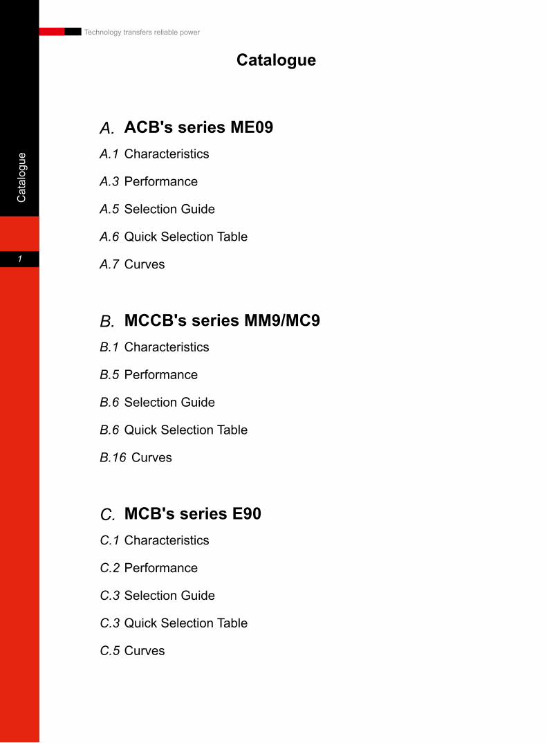
ACB's series ME09Characteristics
Performance
Selection Guide
Quick Selection Table
Curves
MCCB's series MM9/MC9Characteristics
Performance
Selection Guide
Quick Selection Table
Curves
MCB's series E90Characteristics
Performance
Selection Guide
Quick Selection Table
Curves
Catalogue

A.1
Air C
ircuit Breaker
A
Technology transfers reliable power
Frame current Catalogs In A 400~4000
Frame, Cat. No 1 2
Dimensions
Fixed
W 3P/4P 342/442 432/562
D 3P/4P 352
H 3P/4P 430
Draw-out
W 3P/4P 329/429 419/549
D 3P/4P 422
H 3P/4P 440
ACB's series ME09Characteristics
■ Combining experience with AEG's cutting-edge technology in ACB over the past 50-plus years, our products will meet requirements of Chinese market.
■ Frame current ranges from 400A to 4000A and has only two frame Frame1 and Frame2. These series products have the same height, depth and the same front frame size
■ Whether incoming is top or bottom, the electrical performance will not be influenced.
415V500V
690VType A
Type D
Type H
0
10
20
30
40
50
60
70
80
Icu
[kA
]
Voltage
NEW
Series ME05 in 1955
Series ME07 in 1987
Series ME09 in 2009

A.2
Air
Circ
uit B
reak
er
A
Technology transfers reliable power
■ Powerful M-PRO intellectual trip unit has covered global requirements of clients and supplied clients with understandable and easy-to-use interface.
Overload protection •
Short-circuit protection •
Multi-functional ground-fault protection •
I • 2t protectionNeutral line protection •
Thermal memory •
Communication function •
Fault trip record and indication •
Manual and automatic reset •
Self-test function (self-fault alarming of microprocessor) •
Memory module of protection parameters •
Contact output •
Programmable contact output •
Load monitoring •
Early Trip warning / unload •
■ Powerful communication function
MODBUS RTU terms •RS485 port •Status/breakdown display •Remote drive and parameter adjustment •Display I V W V Var VA Varh Wh PF Hz •
MODBUS RTU 19200 baud rate
■ Multi-functional ground-fault protection ensures complete protection for top and downstream equipments and cables
Unlimited UEF: offer downstream equipment and cables protection •Limited REF: offer main top equipment and cables protection •Backup SEF: offer top and downstream cables and equipment a spare •
option of ground-fault protection
Characteristics
ME09&MPROprotection
SE
F
RE
FU
EF
A.3
Air C
ircuit Breaker
A
Technology transfers reliable power
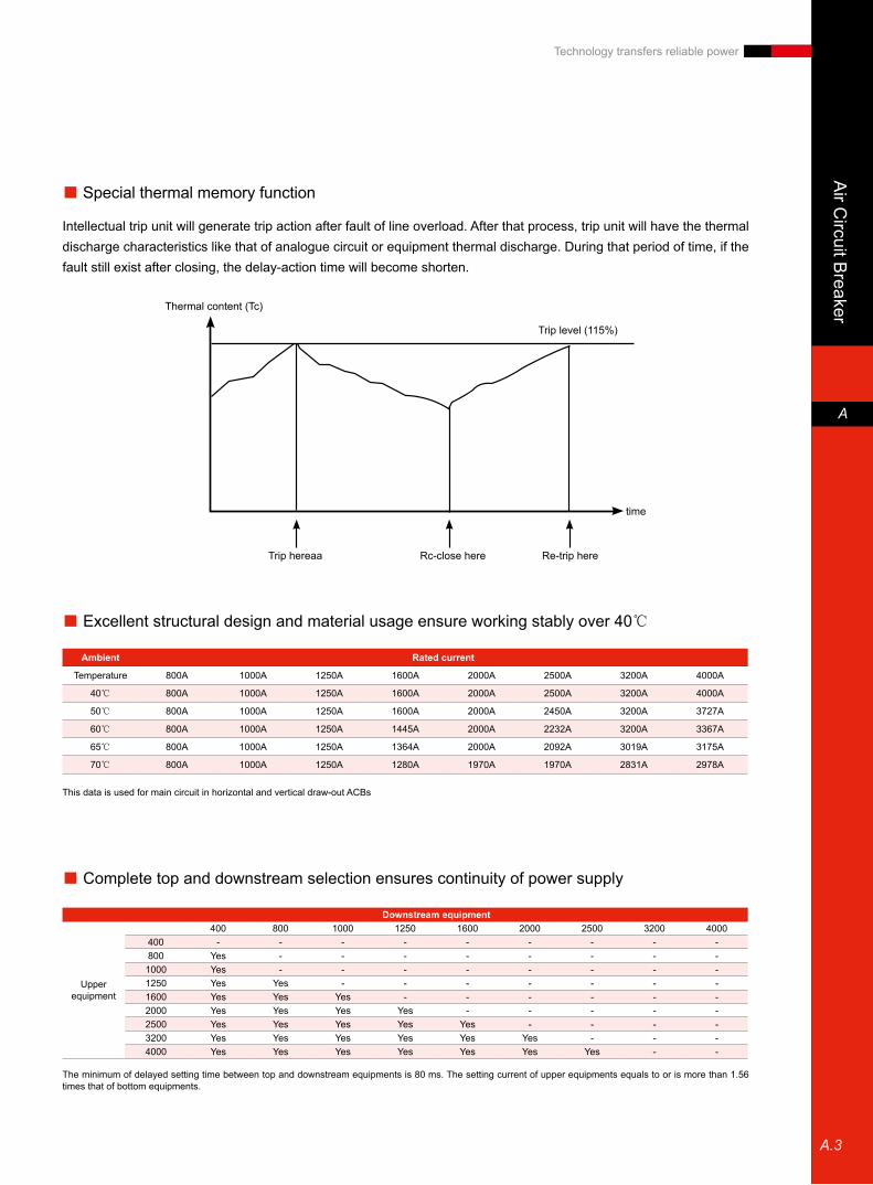
■ Excellent structural design and material usage ensure working stably over 40℃
Ambient Rated current
Temperature 800A 1000A 1250A 1600A 2000A 2500A 3200A 4000A
40℃ 800A 1000A 1250A 1600A 2000A 2500A 3200A 4000A
50℃ 800A 1000A 1250A 1600A 2000A 2450A 3200A 3727A
60℃ 800A 1000A 1250A 1445A 2000A 2232A 3200A 3367A
65℃ 800A 1000A 1250A 1364A 2000A 2092A 3019A 3175A
70℃ 800A 1000A 1250A 1280A 1970A 1970A 2831A 2978A
This data is used for main circuit in horizontal and vertical draw-out ACBs
■ Complete top and downstream selection ensures continuity of power supply
The minimum of delayed setting time between top and downstream equipments is 80 ms. The setting current of upper equipments equals to or is more than 1.56 times that of bottom equipments.
Downstream equipment
Upper equipment
400 800 1000 1250 1600 2000 2500 3200 4000400 - - - - - - - - -800 Yes - - - - - - - -1000 Yes - - - - - - - -1250 Yes Yes - - - - - - -1600 Yes Yes Yes - - - - - -2000 Yes Yes Yes Yes - - - - -2500 Yes Yes Yes Yes Yes - - - -3200 Yes Yes Yes Yes Yes Yes - - -4000 Yes Yes Yes Yes Yes Yes Yes - -
■ Special thermal memory function
Intellectual trip unit will generate trip action after fault of line overload. After that process, trip unit will have the thermal discharge characteristics like that of analogue circuit or equipment thermal discharge. During that period of time, if the fault still exist after closing, the delay-action time will become shorten.
Thermal content (Tc)
Trip level (115%)
Trip hereaa Rc-close here Re-trip here
time
A.4
Air
Circ
uit B
reak
er
A
Technology transfers reliable power
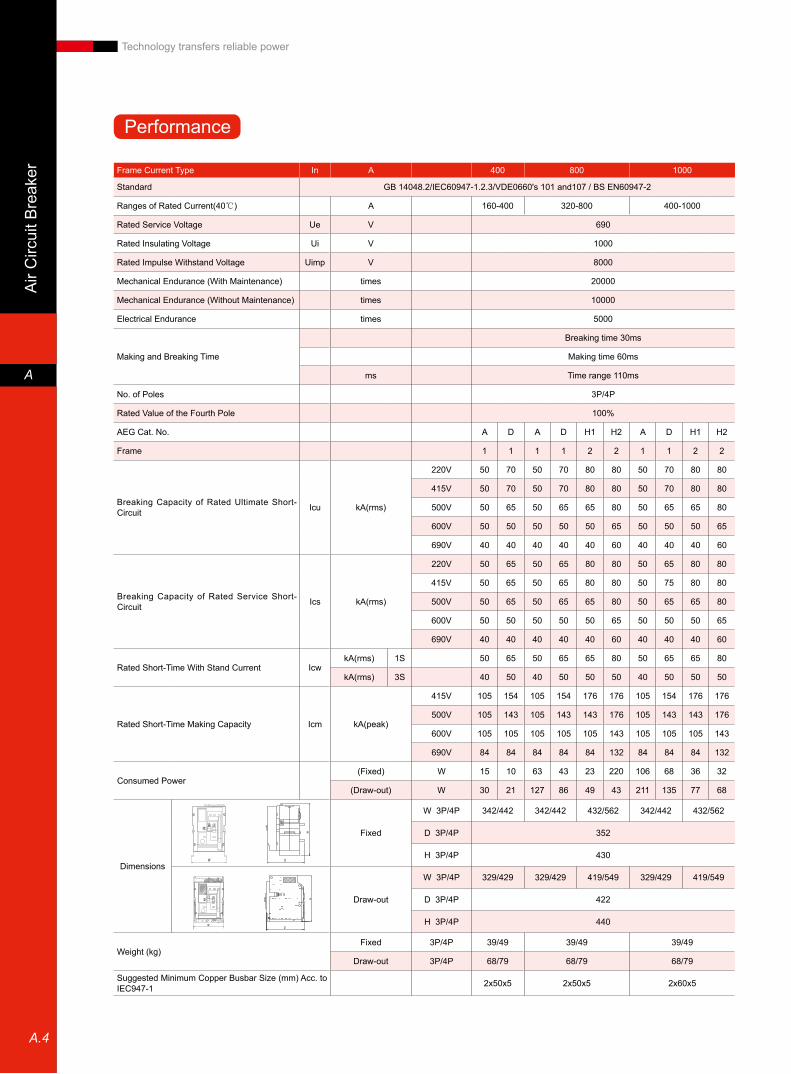
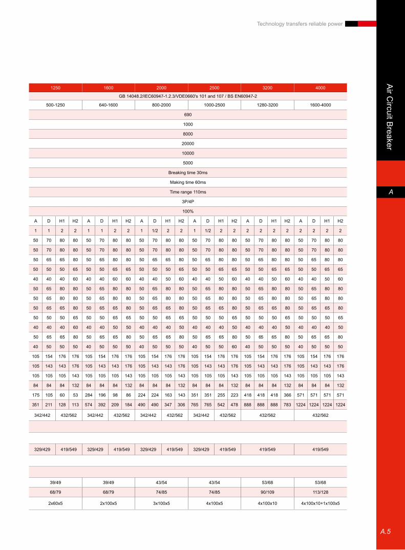
Performance
Frame Current Type In A 400 800 1000
Standard GB 14048.2/IEC60947-1.2.3/VDE0660's 101 and107 / BS EN60947-2
Ranges of Rated Current(40℃) A 160-400 320-800 400-1000
Rated Service Voltage Ue V 690
Rated Insulating Voltage Ui V 1000
Rated Impulse Withstand Voltage Uimp V 8000
Mechanical Endurance (With Maintenance) times 20000
Mechanical Endurance (Without Maintenance) times 10000
Electrical Endurance times 5000
Making and Breaking Time
Breaking time 30ms
Making time 60ms
ms Time range 110ms
No. of Poles 3P/4P
Rated Value of the Fourth Pole 100%
AEG Cat. No. A D A D H1 H2 A D H1 H2
Frame 1 1 1 1 2 2 1 1 2 2
Breaking Capacity of Rated Ultimate Short-Circuit Icu kA(rms)
220V 50 70 50 70 80 80 50 70 80 80
415V 50 70 50 70 80 80 50 70 80 80
500V 50 65 50 65 65 80 50 65 65 80
600V 50 50 50 50 50 65 50 50 50 65
690V 40 40 40 40 40 60 40 40 40 60
Breaking Capacity of Rated Service Short-Circuit Ics kA(rms)
220V 50 65 50 65 80 80 50 65 80 80
415V 50 65 50 65 80 80 50 75 80 80
500V 50 65 50 65 65 80 50 65 65 80
600V 50 50 50 50 50 65 50 50 50 65
690V 40 40 40 40 40 60 40 40 40 60
Rated Short-Time With Stand Current IcwkA(rms) 1S 50 65 50 65 65 80 50 65 65 80
kA(rms) 3S 40 50 40 50 50 50 40 50 50 50
Rated Short-Time Making Capacity Icm kA(peak)
415V 105 154 105 154 176 176 105 154 176 176
500V 105 143 105 143 143 176 105 143 143 176
600V 105 105 105 105 105 143 105 105 105 143
690V 84 84 84 84 84 132 84 84 84 132
Consumed Power (Fixed) W 15 10 63 43 23 220 106 68 36 32
(Draw-out) W 30 21 127 86 49 43 211 135 77 68
Dimensions
Fixed
W 3P/4P 342/442 342/442 432/562 342/442 432/562
D 3P/4P 352
H 3P/4P 430
Draw-out
W 3P/4P 329/429 329/429 419/549 329/429 419/549
D 3P/4P 422
H 3P/4P 440
Weight (kg)Fixed 3P/4P 39/49 39/49 39/49
Draw-out 3P/4P 68/79 68/79 68/79
Suggested Minimum Copper Busbar Size (mm) Acc. to IEC947-1 2x50x5 2x50x5 2x60x5
A.5
Air C
ircuit Breaker
A
Technology transfers reliable power
1250 1600 2000 2500 3200 4000
GB 14048.2/IEC60947-1.2.3/VDE0660's 101 and 107 / BS EN60947-2
500-1250 640-1600 800-2000 1000-2500 1280-3200 1600-4000
690
1000
8000
20000
10000
5000
Breaking time 30ms
Making time 60ms
Time range 110ms
3P/4P
100%
A D H1 H2 A D H1 H2 A D H1 H2 A D H1 H2 A D H1 H2 A D H1 H2
1 1 2 2 1 1 2 2 1 1/2 2 2 1 1/2 2 2 2 2 2 2 2 2 2 2
50 70 80 80 50 70 80 80 50 70 80 80 50 70 80 80 50 70 80 80 50 70 80 80
50 70 80 80 50 70 80 80 50 70 80 80 50 70 80 80 50 70 80 80 50 70 80 80
50 65 65 80 50 65 80 80 50 65 65 80 50 65 80 80 50 65 80 80 50 65 80 80
50 50 50 65 50 50 65 65 50 50 50 65 50 50 65 65 50 50 65 65 50 50 65 65
40 40 40 60 40 40 60 60 40 40 50 60 40 40 50 60 40 40 50 60 40 40 50 60
50 65 80 80 50 65 80 80 50 65 80 80 50 65 80 80 50 65 80 80 50 65 80 80
50 65 80 80 50 65 80 80 50 65 80 80 50 65 80 80 50 65 80 80 50 65 80 80
50 65 65 80 50 65 65 80 50 65 65 80 50 65 65 80 50 65 65 80 50 65 65 80
50 50 50 65 50 50 65 65 50 50 65 65 50 50 50 65 50 50 50 65 50 50 50 65
40 40 40 60 40 40 50 50 40 40 40 50 40 40 40 50 40 40 40 50 40 40 40 50
50 65 65 80 50 65 65 80 50 65 65 80 50 65 65 80 50 65 65 80 50 65 65 80
40 50 50 50 40 50 50 50 40 50 50 50 40 50 50 60 40 50 50 50 40 50 50 50
105 154 176 176 105 154 176 176 105 154 176 176 105 154 176 176 105 154 176 176 105 154 176 176
105 143 143 176 105 143 143 176 105 143 143 176 105 143 143 176 105 143 143 176 105 143 143 176
105 105 105 143 105 105 105 143 105 105 105 143 105 105 105 143 105 105 105 143 105 105 105 143
84 84 84 132 84 84 84 132 84 84 84 132 84 84 84 132 84 84 84 132 84 84 84 132
175 105 60 53 284 196 98 86 224 224 163 143 351 351 255 223 418 418 418 366 571 571 571 571
351 211 128 113 574 392 209 184 490 490 347 306 765 765 542 478 888 888 888 783 1224 1224 1224 1224
342/442 432/562 342/442 432/562 342/442 432/562 342/442 432/562 432/562 432/562
329/429 419/549 329/429 419/549 329/429 419/549 329/429 419/549 419/549 419/549
39/49 39/49 43/54 43/54 53/68 53/68
68/79 68/79 74/85 74/85 90/109 113/128
2x60x5 2x100x5 3x100x5 4x100x5 4x100x10 4x100x10+1x100x5
A.6
Air
Circ
uit B
reak
er
A
Technology transfers reliable power
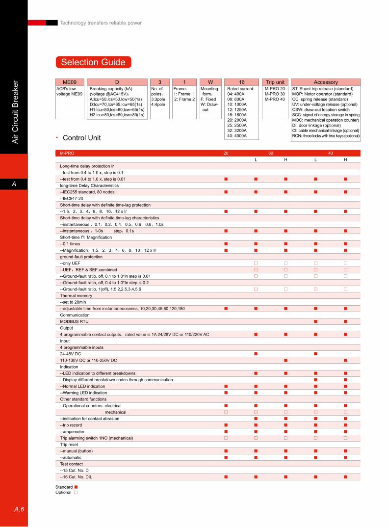
ME09ACB's low voltage ME09
3No. of poles:3:3pole4:4pole
1Frame:1: Frame 12: Frame 2
WMounting form:
F: FixedW: Draw- out
DBreaking capacity (kA)(voltage @AC415V):A:lcu=50,lcs=50,lcw=50(1s)D:lcu=70,lcs=65,lcw=65(1s)H1:lcu=80,lcs=80,lcw=65(1s)H2:lcu=80,lcs=80,lcw=80(1s)
16Rated current:04: 400A 08: 800A10: 1000A 12: 1250A16: 1600A 20: 2000A25: 2500A 32: 3200A40: 4000A
Trip unitM-PRO 20M-PRO 30M-PRO 40
AccessoryST: Shunt trip release (standard)MOP: Motor operator (standard)CC: spring release (standard)UV: under-voltage release (optional)CSW: draw-out location switchSCC: signal of energy storage in springMOC: mechanical operation counter)DI: door linkage (optional)CI: cable mechanical linkage (optional)RON: three locks with two keys (optional)Control Unit •
M-PRO 20 30 40L H L H
Long-time delay protection Ir--test from 0.4 to 1.0 x, step is 0.1--test from 0.4 to 1.0 x, step is 0.01 ■ ■ ■ ■ ■
long-time Delay Characteristics--IEC255 standard, 80 nodes ■ ■ ■ ■ ■
--IEC947-20Short-time delay with definite time-lag protection--1.5,2,3,4,6,8,10,12 x Ir ■ ■ ■ ■ ■
Short-time delay with definite time-lag characteristics--instantaneous ,0.1,0.2,0.4,0.5,0.6,0.8,1.0s--instantaneous ,1-0s step,0.1s ■ ■ ■ ■ ■
Short-time I2t Magnification--0.1 times ■ ■ ■ ■ ■
--Magnification,1.5,2,3,4,6,8,10,12 x Ir ■ ■ ■ ■ ■
ground-fault protection--only UEF □ □ □ □
--UEF,REF & SEF combined □ □ □ □
--Ground-fault ratio, off, 0.1 to 1.0*ln step is 0.01 □ □ □ □
--Ground-fault ratio, off, 0.4 to 1.0*In step is 0.2--Ground-fault ratio, 1(off), 1.5,2,2.5,3,4,5,6 □ □ □ □
Thermal memory--set to 20min--adjustable time from instantaneousness, 10,20,30,45,60,120,180 ■ ■ ■ ■ ■
Communication MODBUS RTU ■ ■
Output4 programmable contact outputs,rated value is 1A 24/28V DC or 110/220V AC ■ ■ ■ ■
Input4 programmable inputs24-48V DC ■ ■
110-130V DC or 110-250V DC ■ ■
Indication--LED indication to different breakdowns ■ ■ ■ ■
--Display different breakdown codes through communication ■ ■
--Normal LED indication ■ ■ ■ ■ ■
--Warning LED indication ■ ■ ■ ■ ■
Other standard functions--Operational counters: electrical ■ ■ ■ ■ ■
mechanical □ □ □ □ □
--indication for contact abrasion ■ ■ ■ ■
--trip record ■ ■ ■ ■ ■
--ampemeter ■ ■ ■ ■ ■
Trip alarming switch 1NO (mechanical) □ □ □ □ □
Trip reset--manual (button) ■ ■ ■ ■ ■
--automatic ■ ■ ■ ■ ■
Test contact--15 Cat. No. D--16 Cat. No. DIL ■ ■ ■ ■ ■
Standard ■Optional □
Selection Guide

A.7
Air C
ircuit Breaker
A
Technology transfers reliable power
Auxiliary •
Parent Breaker •
Rated Current In(A) 400 800 1000 1250 1600 2000 2500 3200 4000
Bre
akin
g ca
paci
ty A
Fixed3P ME09A31F04 ME09A31F08 ME09A31F10 ME09A31F12 ME09A31F16 ME09A31F20 ME09A31F25 ME09A32F32 ME09A32F40
4P ME09A41F04 ME09A41F08 ME09A41F10 ME09A41F12 ME09A41F16 ME09A41F20 ME09A41F25 ME09A42F32 ME09A42F40
Draw-out
3P ME09A31W04 ME09A31W08 ME09A31W10 ME09A31W12 ME09A31W16 ME09A31W20 ME09A31W25 ME09A32W32 ME09A32W40
4P ME09A41W04 ME09A41W08 ME09A41W10 ME09A41W12 ME09A41W16 ME09A41W20 ME09A41W25 ME09A42W32 ME09A42W40
Bre
akin
g ca
paci
ty D
Fixed3P ME09D31F04 ME09D31F08 ME09D31F10 ME09D31F12 ME09D31F16 ME09D31F20 ME09D31F25 ME09D32F32 ME09D32F40
4P ME09D41F04 ME09D41F08 ME09D41F10 ME09D41F12 ME09D41F16 ME09D41F20 ME09D41F25 ME09D42F32 ME09D42F40
Draw-out
3P ME09D31W04 ME09D31W08 ME09D31W10 ME09D31W12 ME09D31W16 ME09D31W20 ME09D31W25 ME09D32W32 ME09D32W40
4P ME09D41W04 ME09D41W08 ME09D41W10 ME09D41W12 ME09D41W16 ME09D41W20 ME09D41W25 ME09D42W32 ME09D42W40
Bre
akin
g ca
paci
ty H
1
Fixed3P ME09H132F08 ME09H132F10 ME09H132F12 ME09H132F16 ME09H132F20 ME09H132F25 ME09H132F32 ME09H132F40
4P ME09H142F08 ME09H142F10 ME09H142F12 ME09H142F16 ME09H142F20 ME09H142F25 ME09H142F32 ME09H142F40
Draw-out
3P ME09H132W08 ME09H132W10 ME09H132W12 ME09H132W16 ME09H132W20 ME09H132W25 ME09H132W32 ME09H132W40
4P ME09H142W08 ME09H142W10 ME09H142W12 ME09H142W16 ME09H142W20 ME09H142W25 ME09H142W32 ME09H142W40
Bre
akin
g ca
paci
ty H
2
Fixed3P ME09H232F08 ME09H232F10 ME09H232F12 ME09H232F16 ME09H232F20 ME09H232F25 ME09H232F32 ME09H232F40
4P ME09H242F08 ME09H242F10 ME09H242F12 ME09H242F16 ME09H242F20 ME09H242F25 ME09H242F32 ME09H242F40
Draw-out
3P ME09H232W08 ME09H232W10 ME09H232W12 ME09H232W16 ME09H232W20 ME09H232W25 ME09H232W32 ME09H232W40
4P ME09H242W08 ME09H242W10 ME09H242W12 ME09H242W16 ME09H242W20 ME09H242W25 ME09H242W32 ME09H242W40
DevicesRated voltage (V)
Normal operating range Consuming power under rated current (resistiveness)AC DC
Auxiliary switches on breakers
250 - - 10A
- 125 - 5A on-off
- 250 - 0.25 AC23, DC3, 2 contacts in series
Position switches on breakers
250 - - 10A
- 125 - 0.5A on-off
- 250 - 0.25
ST、CC110-130220-250380-440
24-3048
110-130220-250
0.7~1.1X rated voltage (ST)0.85-1.1Xrated voltage (CC) AC-300VA
DC-250W
UVR110-130220-250380-440
30-48110-130
Pick-up voltage0,85-1.1X rated voltage released
0.7-0.35X rated voltage
300VA, down to 20WA after 0.4 seconds
UVTD 220-250380-440 42-48 3±1s time delay 350VA on
20VA off
MOP110-130220-250380-440
24-3048-60
110-130220-250
0,85-1.1X storage time under rated voltage needs less than 3
seconds
AC-50VADC-50W
Quick Selection Table
A.8
Air
Circ
uit B
reak
er
A
Technology transfers reliable power
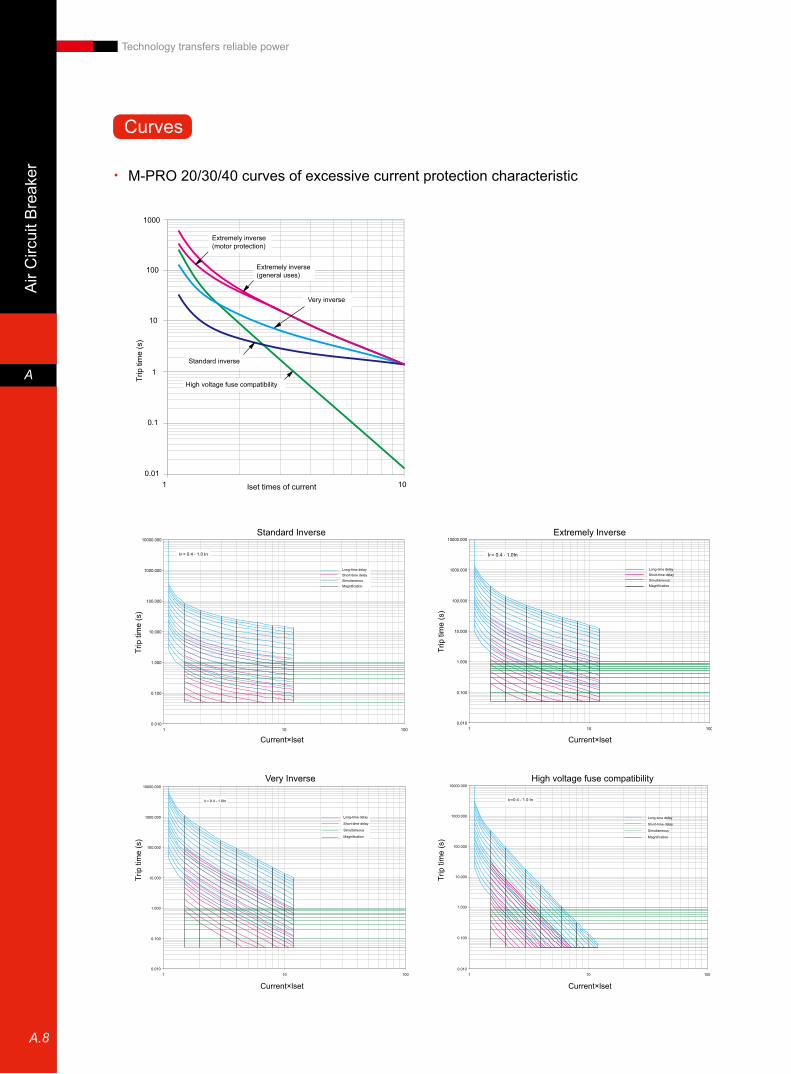
Long-time delayShort-time delaySimultaneousMagnification
Current×lset
Trip
tim
e (s
)
Long-time delayShort-time delaySimultaneousMagnification
Trip
tim
e (s
)
Current×lset
lset times of current
Trip
tim
e (s
)
Long-time delay
Short-time delay
Simultaneous
Magnification
Trip
tim
e (s
)
Current×lset Current×lset
Long-time delay
Short-time delay
Simultaneous
Magnification
Trip
tim
e (s
)
Ir=0.4 - 1.0 In
Extremely inverse (motor protection)
Extremely inverse (general uses)
Very inverse
Standard inverse
High voltage fuse compatibility
Standard Inverse Extremely Inverse
Very Inverse High voltage fuse compatibility
M-PRO 20/30/40 curves of excessive current protection characteristic •
Curves
A.9
Air C
ircuit Breaker
A
Technology transfers reliable power
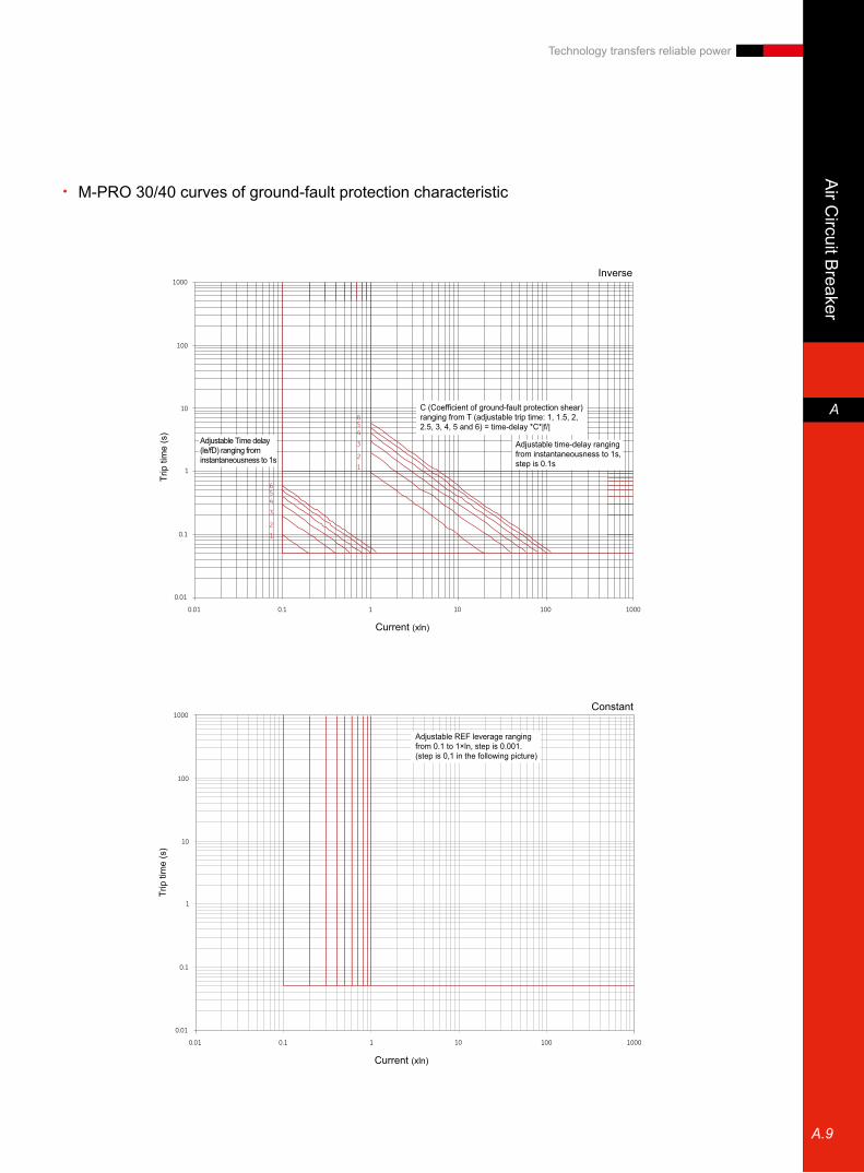
M-PRO 30/40 curves of ground-fault protection characteristic •
Inverse
Current (xln)
Trip
tim
e (s
)
Constant
Current (xln)
Trip
tim
e (s
)
Adjustable Time delay (le/fD) ranging from instantaneousness to 1s
Adjustable time-delay ranging from instantaneousness to 1s, step is 0.1s
Adjustable REF leverage ranging from 0.1 to 1×ln, step is 0.001.(step is 0,1 in the following picture)
C (Coefficient of ground-fault protection shear) ranging from T (adjustable trip time: 1, 1.5, 2, 2.5, 3, 4, 5 and 6) = time-delay *C*|f/|

Mou
lded
Cas
e C
ircui
t-bre
aker
B
B.1
Technology transfers reliable power
■ Excellent overall breaking capacity offers clients more options and can meet requirements of different circumstances and industries.
MM169AC 415V MC169/259 MC409/639
Ics=100%Icu
■ The current of this series is up to 630A. There are 5 kinds of frame current, 21 kinds of rated current and 4 breaking capacity with only 3 dimensions (w×h×d)
MCCB's series MM9/MC9
81mm×130mm×85mm
MM169
105mm×170mm×95mm
MC169/259
140mm×265mm×115mm
MC 409/639
Breaking capacity of rated ultimate short-circuit Icu:
Breakers must break this current for two times • without doing any damages
After the second short-circuit, breakers must be • changed or put into senquence test.
Test sequence:Icu:O – t – CO •
Breaking capacity of rated service short-circuit Ics:
Breakers must break the current for three times • without doing any damages
Before maintenance, breakers can still transmit • rated current.
Test order:Ics:O – t – CO – t – CO •
Characteristics
Moulded C
ase Circuit-breaker
B
B.2
Technology transfers reliable power
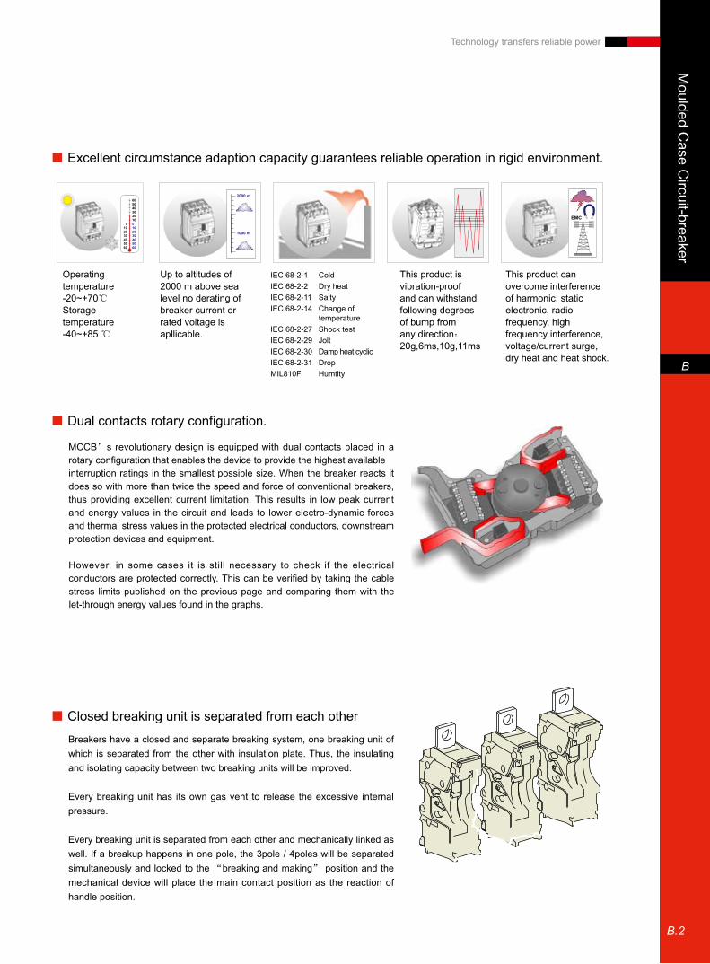
■ Excellent circumstance adaption capacity guarantees reliable operation in rigid environment.
Operating temperature-20~+70℃Storage temperature-40~+85 ℃
Up to altitudes of2000 m above sea level no derating ofbreaker current or rated voltage isapllicable.
This product is vibration-proof and can withstand following degrees of bump from any direction:20g,6ms,10g,11ms
This product can overcome interference of harmonic, static electronic, radio frequency, high frequency interference, voltage/current surge, dry heat and heat shock.
IEC 68-2-1 ColdIEC 68-2-2 Dry heatIEC 68-2-11 SaltyIEC 68-2-14 Change of
temperatureIEC 68-2-27 Shock testIEC 68-2-29 JoltIEC 68-2-30 Damp heat cyclicIEC 68-2-31 DropMIL810F Humtity
■ Dual contacts rotary configuration.
MCCB’s revolutionary design is equipped with dual contacts placed in a rotary configuration that enables the device to provide the highest availableinterruption ratings in the smallest possible size. When the breaker reacts it does so with more than twice the speed and force of conventional breakers, thus providing excellent current limitation. This results in low peak current and energy values in the circuit and leads to lower electro-dynamic forces and thermal stress values in the protected electrical conductors, downstream protection devices and equipment.
However, in some cases it is still necessary to check if the electrical conductors are protected correctly. This can be verified by taking the cable stress limits published on the previous page and comparing them with the let-through energy values found in the graphs.
■ Closed breaking unit is separated from each other
Breakers have a closed and separate breaking system, one breaking unit of which is separated from the other with insulation plate. Thus, the insulating and isolating capacity between two breaking units will be improved.
Every breaking unit has its own gas vent to release the excessive internal pressure.
Every breaking unit is separated from each other and mechanically linked as well. If a breakup happens in one pole, the 3pole / 4poles will be separated simultaneously and locked to the “breaking and making” position and the mechanical device will place the main contact position as the reaction of handle position.

Mou
lded
Cas
e C
ircui
t-bre
aker
B
B.3
Technology transfers reliable power
M
Without overload protection(line stands for breakers’
thermal endurance)
Short-circuit protection
without time-delayRapid trip
unit
Current
Tim
e
Selective thermal and magnetic protection (S) •
For MC169/259 frame
Supply overload and short-circuit protection
Overload 0.8~1×In
Short-circuit 5~10×In
For line protection
Selective enhanced protection with downstream equipments Trip unit is switchable
S
Overload protection for line protection
Short-circuit protection
without time-delay
Rapid trip unit
Current
Tim
e
L
Overload protection for line protection
Short-circuit protection
without time-delay
Rapid trip unit
Current
Tim
e
Characteristics
■ Complete trip unit protection will meet all clients' requirement.
Standard thermal and magnetic protection (L) •
For MM169 frame
Supply overload and short-circuit protection
Overload 0.8~1×In
Short-circuit 10×In
For line protection
Trip unit is not switchable
Motor protection (M) •
For MM169, MC169/259, MC409/639 frame
Supply short-circuit protection
Short-circuit 7~15×In
For motor protection co-ordinate with thermal relay
For MC frame, the trip unit is switchable.
Moulded C
ase Circuit-breaker
B
B.4
Technology transfers reliable power
RPS43250-250
E
Overload protection to motors or lines(LT)
Time-delay short-circuit protection (depending on current)
Filtered high electronic level(1) short-circuit
protection
Rapid trip unit
Current
Tim
e
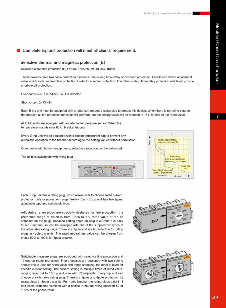
Selective thermal and magnetic protection (E) •
Selective electronic protection (E) For MC 169/259, MC409/639 frame
These devices have two basic protection functions: one is long time-delay or overload protection. Clients can define adjustment value which switches from line protection to electrical motor protection. The other is short time-delay protection which will provide short-circuit protection.
Overload:0.625~1×ln/line, 0.4~1×ln/motor
Short circuit: 2~13×ln
Each E trip unit must be equipped with a rated current and a rating plug to protect this device. When there is no rating plug on the breaker, all the protection functions will perform, but the setting value will be reduced to 15% to 20% of the rated value.
All E trip units are equipped with an internal temperature sensor. When the temperature mounts over 90℃, breaker tripped.
Every E trip unit will be equipped with a closed transparent cap to prevent any automatic operation to the breaker according to the setting values without permission.
Co-ordinate with bottom equipments, selective protection can be enhanced.
Trip units is switchable with rating plug
Each E trip unit has a rating plug, which allows user to choose rated current, protection pole or protection range flexibly. Each E trip unit has two types: adjustable type and switchable type.
Adjustable rating plugs are specially designed for line protection, the protection range of which is from 0.625 to 1×(rated value of the 16 setpoints on the plug). Because setting value on plug is current, it is easy to set. Each trip unit can be equipped with one of the supplied two types of the adjustable rating plugs. There are 3pole and 4pole protection for rating plugs in 4pole trip units. The rated neutral line value can be chosen from phase 50% to 100% for 4pole breaker.
Switchable measure plugs are equipped with selective line protection and 10-degree motor protection. These devices are equipped with two setting knobs: one is used for rated value and range choosing, the other is used for specific current setting. The current setting is multiple times of rated value, ranging from 0.4 to 1×trip unit size with 32 setpoints. Every trip unit can choose a switchable rating plug. There are 3pole and 4pole protection for rating plugs in 4pole trip units. For 4pole breaker the rating plugs exist in 3 and 4pole protected versions with a choice in neutral rating between 50 or 100% of the phase value.
■ Complete trip unit protection will meet all clients' requirement.

Mou
lded
Cas
e C
ircui
t-bre
aker
B
B.5
Technology transfers reliable power
RPA43400-400 MC639-F
F
Multiple overload protections(LT)time delay ranges(LTD)
filtered high electronic short-circuit protection
Multiple short-circuit protection(ST)time delay ranges(STD)
or energy curve(I2T)
Rapid trip unit
Current
Tim
e
Enhanced electronic protection (F) •
for MC409/639 frame
This device is an electronic trip unit offering a fixed set of sophisticated protective functions that can be extended at will by the addition of separately available modules. The device has affixed set of 3 protective functions allowing a selective and fully adjustable protection against overloads (LT) and short-circuits (ST and I ). Both the LT and ST protection can be set to different time settings (LTD and STD) whilst the ST device can be switched to a energy protection mode (I2t).
Overload: 0.4~1×In, 6 time settings, 2 used for motors and 4 used for line
Short-circuit: 1.5~12×In, 5 time settings, time selectiveness
Each F trip unit is equipped with a rated current and a rating plug to protect this device. When there are no rating plugs on the breaker, all protective functions will continue to perform, but the setting value will be reduced to 15% of the rated value of the tripping unit.
All F trip units have a built-in temperature sensor that trips the breaker at temperatures above 95℃, it thus prevents the breaker and electrical components in its immediate vicinity from over heating.
Each F trip unit comes with a transparent, tamper-free (sealable) cover, this to prevent unauthorized manipulation of the breaker settings.
Coupled with bottom equipments, selective protection will be enhanced.
Trip unit is switchable with a rating plug.
Each F rating plug has two setting knobs. The first is used for the setting of the overload current device (LT) and has a setting range of 0.625 to 1×the chosen rating over 16 setpoints. The settings on the devices are in current values thus avoiding the use of complicated multipliers. The second knob is used to set the time delay band of the overload protection (LTD) and has 6 possible time settings.
Each trip unit size can be equipped with one of two available adjustable rating plug types.There is a version of the trip unit without rating plug and one in which the two rating plug types are included. For 4pole trip units the rating plugs exist in 3 and 4 pole protected versions with a choice in neutral rating between 50 or 100% of the phase value.
Characteristics
RPA13025-025

Moulded C
ase Circuit-breaker
B
B.6
Technology transfers reliable power
Extended modules of F tripping unit •
Each F device can be equipped with two plug-in elements, a rating plug and an extension module. The extension modules are simple plug-in devices that allow the user to enhance the F as a protective device or to add in extra functional features. There is a single function module available with Ammeter and a range of functional modules each adding two functions to the device this allows an F to be equipped with.
Ground fault protection •Designed for protection against indirect contact, the ground fault device measures the vectorial sum of the three phase currents
and, if present, that of the neutral conductor. If the sum of these values exceeds the set current thresholds for a period of time
greater than the set time delay, the breaker is tripped. The Ground Fault protection option is adjustable from 0.2 to 1×the
chosen sensor ratings in 9 steps. The user can also define one of 5 delay time range (GFD) designed to allow selectivity between
different sensor ratings.
The GFD device can be set to an “energy curve mode”. This mode changes the fixed delay and reaction time value of the
device. When the set current level is reached, into a reaction time that depends on the energy flowing in the circuit.
A breaker trip due to a ground fault event can be channeled through the communication output (when present) or be wired out to
the contact module (type EMC)
Ground fault alarm •The ground fault alarm option offers the same functionality as the ground fault protection, here however only an alarm signal is
given and the breaker is not tripped. It is adjustable from 0.2 to 1×the chosen sensor ratings in 9 steps. There are 10 steps for
adjusting and one of which is for resetting. The user can also define one of 5 delay time range (GFD).
A breaker trip due to a ground fault event can be channeled through the communication output (when present) or be wired out to
the contact module (type EMC)
Load shedding device •The load shedding device® is designed to allow the user to switch off non priority loads before the LT function trips the breaker
due to an overload. It measures the current within the circuit and provides a signal if the current measured in the three phases
exceeds the set current values. The device has two channels, both adjustable from 0.55 to 1×the set LT protection value (Ir).
Each channel is equipped with a time delay directly proportional to that of the LTD setting. Chanel 1 is set to a time delay equal
to LTD/2 and channel two is set to a time delay of LTD/4. if the current drops below the set thresholds the signal is reset. The
reset signal being given in a time proportional with the chosen LTD curve.
A signal due to a load shedding event can be channeled through the communication output (when present) or be wired out to the
contact module. (type EMC).
■ Complete trip unit protection will meet all clients' requirement.
Mou
lded
Cas
e C
ircui
t-bre
aker
B
B.7
Technology transfers reliable power
Trip cause indicators •In order to indicate the reason of trip, three LED's are provided on the trip unit front panel. One indicating a trip due to the LT
device, one indicating a trip due to the ST device and one for the I device.
Without auxiliary power, the use of the trip reason button is necessary to light up the appropriate LED. With auxiliary power the
use of the trip reason push button is unnecessary.
The three trip signals can be channeled through the communication output (when present) or be wired out as an overload (LT) or
short circuit signal (ST & I) to the contact module (type EMC)
Communication •When a communication option is added to the F trip unit the following data can be viewed:
- The position of the switches on all installed devices.thus providing the settings of the breaker.
- Signals indicating on which of the installed protection devices the breaker has tripped.
- Load shedding orders
- Zone selective interlock occurrences.
A 24V DC auxiliary supply is needed that supplies the system through the external contact module.
Zone selective interlock •A device that allows the user to achieve selectivity combined with the fastest possible fault reaction time. When the ZSI is
active the F trip unit will always trip the breaker as quickly as possible, ignoring the time delays set by means of the STD or
GFD devices. However, when a ZSI signal is received from a downstream breaker equipped with an F, the STD or GFD of the
upstream F device revert to wherever the adjustment is set.
When the breaker is equipped with a “COM” option the ZSI status signal is also available on the carried out through distance
between breaker and auxiliary power is a maximum of 10 meters. With standard cables and auxiliary power, the distance
between breakers to be increased to 1 km. a maximum of five F trip units can be linked in this manner.
Ammeter •Provides the use with the current running in one of the breaker phases. The device has an accuracy of 10% and normally
indicates the current in the highest loaded phase. Use of the push buttons on the module front allows the user to select an
indication of the current in one of the other phases or neutral (if present). After a set delay of 30 seconds the device reverts to its
standard indication setting.

Moulded C
ase Circuit-breaker
B
B.8
Technology transfers reliable power
■ Excellent structure design and material usage ensure the devices working reliably over 40℃.
Thermal and magnetic trip unit •
Maximum Allowed Current Under the Following Ambient Temperatures
TypeFixed breakers plug-in or draw out breakers
In(A) 40℃ 45℃ 50℃ 55℃ 60℃ 65℃ 70℃ 40℃ 45℃ 50℃ 55℃ 60℃ 65℃ 70℃
MM169
16 16.0 15.5 15.0 14.6 14.1 13.6 13.1 15.0 14.6 14.1 13.7 13.2 12.325 25.0 24.3 23.5 22.8 22.0 21.3 20.5 23.5 22.8 22.1 21.4 20.7 19.332 32.0 31.0 30.1 29.1 28.2 27.2 26.2 30.1 29.2 28.3 27.4 26.5 24.740 40.0 38.8 37.6 36.4 35.2 34.0 32.8 37.6 36.5 35.3 34.2 33.1 30.850 50.0 48.5 47.0 45.5 44.0 42.5 41.0 47.0 45.6 44.2 42.8 41.4 38.563 63.0 61.1 59.2 57.3 55.4 53.6 51.7 59.2 57.4 55.7 53.9 52.1 48.680 80.0 77.6 75.2 72.8 70.4 68.0 65.6 75.2 72.9 70.7 68.4 66.2 61.7100 100 97.0 94.0 91.0 88.0 85.0 82.0 94.0 91.2 88.4 85.5 82.7 77.1125 125 121 118 114 110 106 103 118 144 110 107 103 100 96160 160 155 150 146 141 136 131
MC259
125 125 121 118 114 110 106 103 118 144 110 107 103 100 96160 160 155 150 146 141 136 131 150 146 141 137 132 128 123200 200 194 188 182 176 170 164 188 182 177 171 165 160 154250 250 243 235 228 220 213 205 235 228 221 214 207 200 193
MM169 with RCD
16 16.0 15.5 15.0 14.6 14.1 13.6 13.1 15.0 14.6 14.1 13.7 13.2 12.8 12.325 25.0 24.3 23.5 22.8 22.0 21.3 20.5 23.5 22.8 22.1 21.4 20.7 20.0 19.332 32.0 31.0 30.1 29.1 28.2 27.2 26.2 30.1 29.2 28.3 27.4 26.5 25.6 24.740 40.0 38.8 37.6 36.4 35.2 34.0 32.8 37.6 36.5 35.3 34.2 33.1 32.0 30.850 50.0 48.5 47.0 45.5 44.0 42.5 41.0 47.0 45.6 44.2 42.8 41.4 40.0 38.563 63.0 61.1 59.2 57.3 55.4 53.6 51.7 59.2 57.4 55.7 53.9 52.1 50.3 48.680 80.0 77.6 75.2 72.8 70.4 68.0 65.6 75.2 72.9 70.7 68.4 66.2 63.9 61.7100 100 97.0 94.0 91.0 88.0 85.0 82.0 94.0 91.2 88.4 85.5 82.7 79.9 77.1
MM169 with RCD
125 119 115 110 108 97 101 97 110 107 104 101 97 94 91160 152 147 141 138 125 129 125 141 137 133 129 124 120 116
MM259 with RCD
125 125 121 118 114 110 106 103 118 114 110 107 103 100 96160 152 147 141 138 125 129 125 141 137 133 129 124 120 116200 190 184 177 173 156 162 156 177 171 166 161 156 150 145250 238 230 221 216 195 202 195 221 214 208 201 194 188 181
Electronic trip unit •
Maximum Allowed Current Under the Following Ambient Temperatures
Type
Fixed Breakers Plug-in or Draw Out BreakersIs(1)(A) 40℃ 45℃ 50℃ 55℃ 60℃ 65℃ 70℃ 40℃ 45℃ 50℃ 55℃ 60℃ 65℃ 70℃
MC169
25 25 25 25 25 25 25 25 25 25 25 25 25 25 2563 63 63 63 63 63 63 63 63 63 63 63 63 63 63125 125 125 125 125 125 125 125 125 125 125 125 125 125 125160 160 160 160 156 152 148 144 160 156 152 148 144 140 136
MC169/259125 125 125 125 125 125 125 125 125 125 125 125 125 125 125160 160 160 160 160 160 160 160 160 156 152 148 144 140 136250 250 250 250 244 238 231 225 250 244 238 231 225 219 213
MC409250 250 250 250 250 250 250 250 250 250 250 250 250 250 250350 350 350 350 350 350 350 350 350 350 350 350 350 350 340400 400 400 400 390 380 370 360 400 390 380 370 360 350 340
MC639400 400 400 400 400 400 400 400 400 400 400 400 400 400 400500 500 500 500 500 500 500 500 500 500 500 500 500 500 481630 630 614 599 583 567 551 536 583 568 554 539 524 510 481
MM169 with RCD
25 25 25 25 25 25 25 25 25 25 25 25 25 25 2563 63 63 63 63 63 63 63 63 63 63 63 63 63 63
125 125 125 125 125 125 125 125 125 125 125 125 125 125 106160 160 156 152 148 144 141 137 152 148 144 141 137 133 129
MM259 with RCD
125 125 125 125 125 125 125 125 125 125 125 125 125 125 125160 160 160 160 160 160 160 160 160 160 160 160 160 160 160250 250 244 238 244 238 231 225 238 232 226 220 214 208 202
MM409 with RCD
250 250 250 250 250 250 250 250 250 250 250 250 250 250 250350 350 350 350 341 333 324 315 350 351 342 333 324 315 306400 400 370 360 350 340 330 320 360 351 342 333 324 315 306
MM639 with RCD
400 400 400 400 400 400 400 400 400 400 400 400 400 400 400500 500 500 500 500 500 500 488 500 500 494 481 468 455 442630 630 567 551 536 520 504 488 520 507 494 481 468 455 442
Characteristics
(1) Current sensor

Mou
lded
Cas
e C
ircui
t-bre
aker
B
B.9
Technology transfers reliable power
■ Good Upper And Downstream Selectivity Ensures Continuity of Power Supply
Selective Table
Downstream In(A)
Upstream MCE169 S,H,X
Unit AMCS259 S,H,X
Unit AMCE259 S,H,X
Unit AMCE409/639 S,H,X、MCF409/639 S,H,X
Unit A
63 125 160 125 160 200&250 125 160 250 400-250
400-350
400-400
630-400
630-500
630-630
Selective Current Limit (kA)
E90 C Curve
≤40 T T T T T T T T T T T T T T T
50 -- T T T T T T T T T T T T T T
63 -- T T -- T T -- T T T T T T T T
MML169N
≤32 T T T T T T T T T T T T T T T
40 T T T T T T T T T T T T T T T
50 -- T T T T T T T T T T T T T T
63 -- T T T T T T T T T T T T T T
80 -- T T T T T T T T T T T T T T
100 -- -- T -- T T -- T T T T T T T T
125 -- -- -- -- -- T -- -- T T T T T T T
160 -- -- -- -- -- T -- -- T T T T T T T
MMM169 S,H,X
≤32 T T T T T T T T T T T T T T T
40 42 42 42 42 42 42 50 50 50 T T T T T T
50 -- 42 42 42 42 42 50 50 50 T T T T T T
63 -- 42 42 42 42 42 50 50 50 T T T T T T
80 -- 42 42 42 42 42 50 50 50 T T T T T T
100 -- -- 42 -- 42 42 -- 50 50 T T T T T T
125 -- -- -- -- -- 42 -- -- 50 T T T T T T
160 -- -- -- -- -- 42 -- -- 50 T T T T T T
MCM169 S.H.X
≤32 30 30 30 30 30 30 36 36 36 T T T T T T
40 30 30 30 30 30 30 36 36 36 T T T T T T
50 -- 30 30 30 30 30 36 36 36 T T T T T T
63 -- 30 30 30 30 30 36 36 36 T T T T T T
80 -- 30 30 -- 30 30 -- 36 36 T T T T T T
100 -- -- 30 -- 30 30 -- 36 36 T T T T T T
125 -- -- -- -- -- 30 -- -- 36 -- T T T T T
160 -- -- -- -- -- 30 -- -- 36 T T T T T T
MCS169 S.H.XMCE169 S.H.X
≤32 0.8 1.8 2.2 1.3 1.6 2.5 1.8 2.2 3.5 T T T T T T
40 0.8 1.8 2.2 1.3 1.6 2.5 1.8 2.2 3.5 T T T T T T
50 -- 1.8 2.2 -- 1.6 2.5 -- 2.2 3.5 T T T T T T
63 -- 1.8 2.2 -- 1.6 2.5 -- 2.2 3.5 T T T T T T
80 -- -- 2.2 -- 1.6 2.5 -- 2.2 3.5 T T T T T T
100 -- -- 2.2 -- 1.6 2.5 -- 2.2 3.5 T T T T T T
125 -- -- -- -- -- 2.5 -- -- 3.5 T T T T T T
160 -- -- -- -- -- 2.5 -- -- 3.5 T T T T T T
MCS259 S.H.XMCE259 S.H.X
125 -- -- -- -- -- 2.5 -- -- 3.5 15 15 15 T T T
160 -- -- -- -- -- -- -- -- -- -- 15 15 T T T
200 -- -- -- -- -- -- -- -- -- -- 15 15 T T T
250 -- -- -- -- -- -- -- -- -- -- 15 15 T T T
MCE409 S.H.X
250 -- -- -- -- -- -- -- -- -- -- -- -- 6 6 6
350 -- -- -- -- -- -- -- -- -- -- -- -- -- 6 6
400 -- -- -- -- -- -- -- -- -- -- -- -- -- -- 6
*T: all selectivity: have selectivity in downstream switches Icu when short-circuit occurs.

Moulded C
ase Circuit-breaker
B
B.10
Technology transfers reliable power
Performance
Breaker Type MM169 MC169 MC259 MC409 MC639
Standard GB 14048.2/IEC60947-1.2.3/VDE0660's 101 and 107/BS EN60947-2Description of Breaking Capacity N S H X S H X S H X S H X S H X
No. of poles 3P,4P 3P,4P 3P,4P 3P,4P 3P,4P
Rated Insulting Voltage Ui(V) 750 750 750 750 750
Rated Impulse Withstand Voltage
Uimp(kV) 8 8 8 8 8
Rated Operating Voltage
V AC 690 690 690 690 690
V DC 500 500 500 - -
Usage Category A A A B(2) B(2)
Isolation Application Indication of ON/OFF Yes Yes Yes Yes Yes
Rated Current Ith=Ie Current under 40℃(A) 63/160 160 250 400 630
Limit Breaking CapacityIcu(kA)
230/240 VAC 50 85 100 200 85 100 200 85 100 200 85 100 200 85 100 200
400/415 VAC 36 50 80 150 50 80 150 50 80 150 50 80 150 50 80 150
440 VAC 25 30 65 130 42 65 130 42 65 130 42 65 130 42 65 130
500 VAC 18 22 36 50 30 50 100 30 50 100 30 50 100 30 50 100
690 VAC 6 8 10 12 10 22 75 10 15 22 10 22 75(3) 10 22 40(3)
250 VDC Single pole 25 40 65 100 50 85 100 50 85 100 10 22 - - - -
500 VDC Double poles - 40 65(1) 100(1) 50 85(1) 100(1) 50 85(1) 100(1) - - - - - -
Breaking CapacityIcs(%Icu)
≤500 VAC 100% 100% 100% 100% 100%
690 VAC 100% 100% 75% 50% 100% 75% 25% 100% 75% 50% 100% 45% 25% 100% 45% 25%
NEMA AB1 Three Phases of Breaking Capacity (kA)
240 VAC 50 65 100 150 100 150 200 100 150 200 100 150 200 100 150 200
480 VAC 25 36 50 65 50 65 130 50 65 130 50 65 130 50 65 130
600 VAC 10 22 25 36 25 36 42 25 36 42 25 36 42 25 36 42
Endurance(CO Operation)
Mechanical 10000 25000 40000 25000 20000 20000
Electrical (In) 5000 10000 20000 10000 7500 5000
Electrical (In/2) 10000 20000 30000 20000 15000 10000
Trip unit
switchable No Yes Yes Yes Yes
thermal and magnetic standard(L) ■ ■ ■ ■ - - - - - - - - - - - -
thermal and magnetic selectivity(S) - - - - ■ ■ ■ ■ ■ ■ - - - - - -
motor protection(M) - ■ ■ ■ ■ ■ ■ ■ ■ ■ ■ ■ ■ ■ ■ ■
electrical selectivity(E) - - - - ■ ■ ■ ■ ■ ■ ■ ■ ■ ■ ■ ■
electrical enhanced(F) - - - - - - - - - - ■ ■ ■ ■ ■ ■
Installation
DIN tracking installation Yes No No No No
Fixed Yes Yes Yes Yes Yes
plug-in Yes Yes Yes Yes Yes
draw out - Yes Yes Yes Yes
Dimensions(Width×Height×Depth)
3pole fixed front connection 81x130x85 105x170x95 105x170x95 140x265x115 140x265x115
4pole fixed front connection 108x130x85 140x170x95 140x170x95 185x265x115 185x265x115
Weight(kg)
3pole fixed front connection 0.9 1.5 1.6 4.5 4.5
4pole fixed front connection 1.3 2 2.1 6 6
1. 3pole in series2. Only for 400A and 500A3. When MC409/639X is used under 690v, a long and wide terminal shield must be equipped
Mou
lded
Cas
e C
ircui
t-bre
aker
B
B.11
Technology transfers reliable power
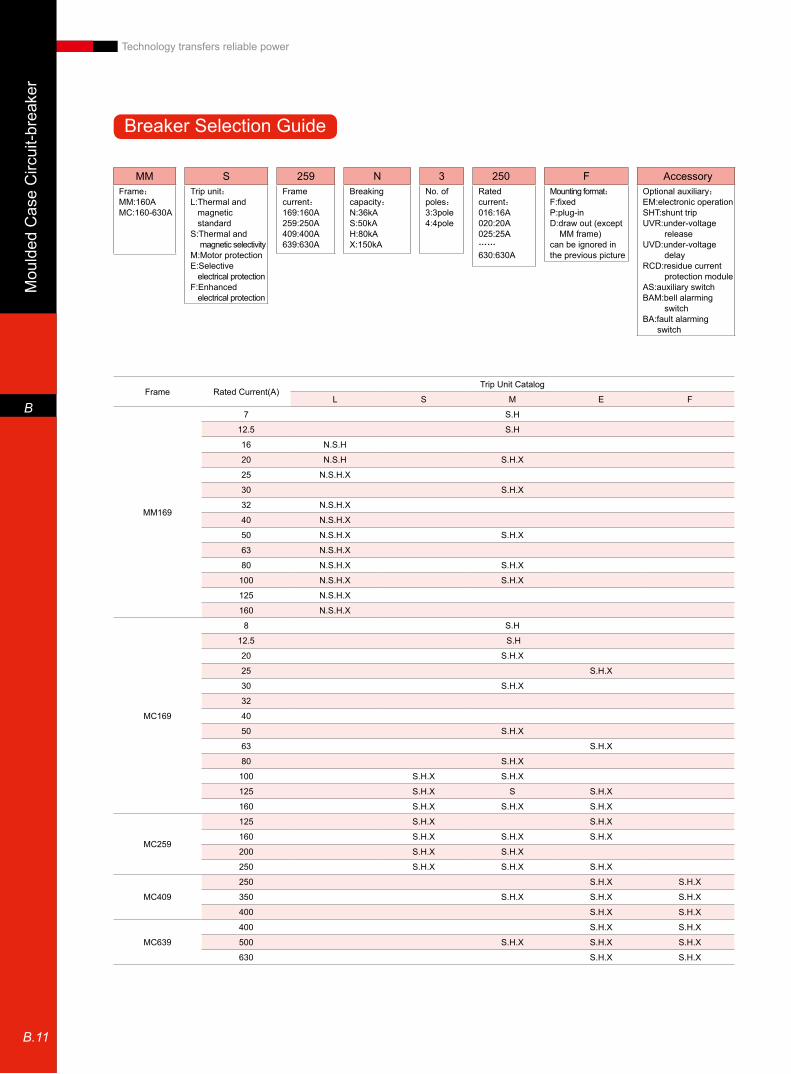
Breaker Selection Guide
MMFrame:MM:160AMC:160-630A
3No. of poles:3:3pole4:4pole
FMounting format:F:fixedP:plug-inD:draw out (except MM frame)can be ignored in the previous picture
NBreaking capacity:N:36kAS:50kAH:80kAX:150kA
250Rated current:016:16A020:20A025:25A……630:630A
STrip unit:L:Thermal and magnetic standardS:Thermal and magnetic selectivityM:Motor protectionE:Selective electrical protectionF:Enhanced electrical protection
AccessoryOptional auxiliary:EM:electronic operationSHT:shunt tripUVR:under-voltage releaseUVD:under-voltage delayRCD:residue current protection moduleAS:auxiliary switchBAM:bell alarming switchBA:fault alarming switch
259Frame current:169:160A259:250A409:400A639:630A
Frame Rated Current(A)Trip Unit Catalog
L S M E F
MM169
7 S.H
12.5 S.H
16 N.S.H
20 N.S.H S.H.X
25 N.S.H.X
30 S.H.X
32 N.S.H.X
40 N.S.H.X
50 N.S.H.X S.H.X
63 N.S.H.X
80 N.S.H.X S.H.X
100 N.S.H.X S.H.X
125 N.S.H.X
160 N.S.H.X
MC169
8 S.H
12.5 S.H
20 S.H.X
25 S.H.X
30 S.H.X
32
40
50 S.H.X
63 S.H.X
80 S.H.X
100 S.H.X S.H.X
125 S.H.X S S.H.X
160 S.H.X S.H.X S.H.X
MC259
125 S.H.X S.H.X
160 S.H.X S.H.X S.H.X
200 S.H.X S.H.X
250 S.H.X S.H.X S.H.X
MC409
250 S.H.X S.H.X
350 S.H.X S.H.X S.H.X
400 S.H.X S.H.X
MC639
400 S.H.X S.H.X
500 S.H.X S.H.X S.H.X
630 S.H.X S.H.X

Moulded C
ase Circuit-breaker
B
B.12
Technology transfers reliable power
MML 169- Breakers For Complete Line Protection
Economical / Icu = 36 kA / "N"L: Selective Thermal Overload Trip and Fixed Short-Circuit Trip
3pole protection 4pole protection (1)
Ir A Irm A Cat. No. Cat. No.
12.8-16 10 x In MML169N 3016 MML 169N 4016
16-20 10 x In MML 169N 3020 MML 169N 4020
20-25 10 x In MML 169N 3025 MML 169N 4025
25.6-32 10 x In MML 169N 3032 MML 169N 4032
32-40 10 x In MML 169N 3040 MML 169N 4040
40-50 10 x In MML 169N 3050 MML 169N 4050
50.4-63 10 x In MML 169N 3063 MML 169N 4063
64-80 10 x In MML 169N 3080 MML 169N 4080
80-100 10 x In MML 169N 3100 MML 169N 4100
100-125 10 x In MML 169N 3125 MML 169N 4125
128-160 8 x In MML 169N 3160 MML 169N 4160
Standard / Icu = 50 kA / "S"
12.8-16 10 x In MML 169S 3016 MML 169S 4016
16-20 10 x In MML 169S 3020 MML 169S 4020
20-25 10 x In MML 169S 3025 MML 169S 4025
26-32 10 x In MML 169S 3032 MML 169S 4032
32-40 10 x In MML 169S 3040 MML 169S 4040
40-50 10 x In MML 169S 3050 MML 169S 4050
50-63 10 x In MML 169S 3063 MML 169S 4063
64-80 10 x In MML 169S 3080 MML 169S 4080
80-100 10 x In MML 169S 3100 MML 169S 4100
100-125 10 x In MML 169S 3125 MML 169S 4125
128-160 8 x In MML 169S 3160 MML 169S 4160
High breaking capacity / Icu = 80 kA / "H"
12.8-16 10 x In MML 169H 3016 MML 169H 4016
16-20 10 x In MML 169H 3020 MML 169H 4020
20-25 10 x In MML 169H 3025 MML 169H 4025
26-32 10 x In MML 169H 3032 MML 169H 4032
32-40 10 x In MML 169H 3040 MML 169H 4040
40-50 10 x In MML 169H 3050 MML 169H 4050
50-63 10 x In MML 169H 3063 MML 169H 4063
64-80 10 x In MML 169H 3080 MML 169H 4080
80-100 10 x In MML 169H 3100 MML 169H 4100
100-125 10 x In MML 169H 3125 MML 169H 4125
128-160 8 x In MML 169H 3160 MML 169H 4160
Ultra-high breaking capacity / Icu = 150 kA / "X"
20-25 10 x In MML 169X 3025 MML 169X 4025
26-32 10 x In MML 169X 3032 MML 169X 4032
32-40 10 x In MML 169X 3040 MML 169X 4040
40-50 10 x In MML 169X 3050 MML 169X 4050
50-63 10 x In MML 169X 3063 MML 169X 4063
64-80 10 x In MML 169X 3080 MML 169X 4080
80-100 10 x In MML 169X 3100 MML 169X 4100
100-125 10 x In MML 169X 3125 MML 169X 4125
128-160 8 x In MML 169X 3160 MML 169X 4160
(1) Npole is mounted on the left side of the breaker. Please contact us if you want Npole to be mounted on the right side of the breaker
Quick Selection Table
Mou
lded
Cas
e C
ircui
t-bre
aker
B
B.13
Technology transfers reliable power
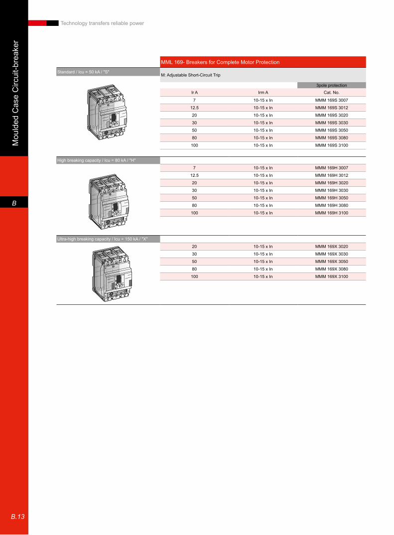
MML 169- Breakers for Complete Motor Protection
Standard / Icu = 50 kA / "S"M: Adjustable Short-Circuit Trip
3pole protectionIr A Irm A Cat. No.
7 10-15 x In MMM 169S 3007
12.5 10-15 x In MMM 169S 3012
20 10-15 x In MMM 169S 3020
30 10-15 x In MMM 169S 3030
50 10-15 x In MMM 169S 3050
80 10-15 x In MMM 169S 3080
100 10-15 x In MMM 169S 3100
High breaking capacity / Icu = 80 kA / "H"
7 10-15 x In MMM 169H 3007
12.5 10-15 x In MMM 169H 3012
20 10-15 x In MMM 169H 3020
30 10-15 x In MMM 169H 3030
50 10-15 x In MMM 169H 3050
80 10-15 x In MMM 169H 3080
100 10-15 x In MMM 169H 3100
Ultra-high breaking capacity / Icu = 150 kA / "X"
20 10-15 x In MMM 169X 3020
30 10-15 x In MMM 169X 3030
50 10-15 x In MMM 169X 3050
80 10-15 x In MMM 169X 3080
100 10-15 x In MMM 169X 3100

Moulded C
ase Circuit-breaker
B
B.14
Technology transfers reliable power
MM169- RCD Unit3pole 4pole(1)
Type Rated Voltage V / AC Cat. No. Cat. No.MM169 220 / 440 DG3 / MM9-2/6 DG4 / MM9-2/6
400 / 690 DG3 / MM9-4/6 DG4 / MM9-4/6
MM169 220 / 440 DD3 / MM9-2/6 DD4 / MM9-2/6
MM169 220 / 440 DB3 / MM9-2/6 DB4 / MM9-2/6400 / 690 DB3 / MM9-4/6 DB4 / MM9-4/6
RCD side mounting typeCode includes the following componentsRCD: DIN track mounting components and multi-directional current transmitting components
RCD base mounting type (under trip unit)
MCS 169/259- Breakers for Complete Line Protection
Standard / Icu = 50 kA / "S"S: Selective Thermal Overload Trip and Fixed Short-Circuit Trip
3pole protection 4pole protection(1)
Type Ir A Irm A Cat. No. Cat. No.MC169 80-100 5-10 x Ir MCS 169S 3100 MCS 169S 4100MC169 100-125 5-10 x Ir MCS 169S 3125 MCS 169S 4125MC169 128-160 5-10 x Ir MCS 169S 3160 MCS 169S 4160
MC259 100-125 5-10 x Ir MCS 259S 3125 MCS 259S 4125MC259 128-160 5-10 x Ir MCS 259S 3160 MCS 259S 4160MC259 160-200 5-10 x Ir MCS 259S 3200 MCS 259S 4200MC259 200-250 5-10 x Ir MCS 259S 3250 MCS 259S 4250
High breaking capacity / Icu = 80 kA / "H"MC169 80-100 5-10 x Ir MCS 169H 3100 MCS 169H 4100MC169 100-125 5-10 x Ir MCS 169H 3125 MCS 169H 4125MC169 128-160 5-10 x Ir MCS 169H 3160 MCS 169H 4160
MC259 100-125 5-10 x Ir MCS 259H 3125 MCS 259H 4125MC259 128-160 5-10 x Ir MCS 259H 3160 MCS 259H 4160MC259 160-200 5-10 x Ir MCS 259H 3200 MCS 259H 4200MC259 200-250 5-10 x Ir MCS 259H 3250 MCS 259H 4250
Ultra-high breaking capacity / Icu = 150 kA / "X"MC169 80-100 5-10 x Ir MCS 169X 3100 MCS 169X 4100MC169 100-125 5-10 x Ir MCS 169X 3125 MCS 169X 4125MC169 128-160 5-10 x Ir MCS 169X 3160 MCS 169X 4160
MC259 100-125 5-10 x Ir MCS 259X 3125 MCS 259X 4125MC259 128-160 5-10 x Ir MCS 259X 3160 MCS 259X 4160MC259 160-200 5-10 x Ir MCS 259X 3200 MCS 259X 4200MC259 200-250 5-10 x Ir MCS 259X 3250 MCS 259X 4250
(1) Npole is mounted on the left side of the breaker. Please contact us if you want Npole to be mounted on the right side of the breaker
Only side connection RCD typeCode includes the following componentsRCD: DIN tracking mounting components and links
Mou
lded
Cas
e C
ircui
t-bre
aker
B
B.15
Technology transfers reliable power
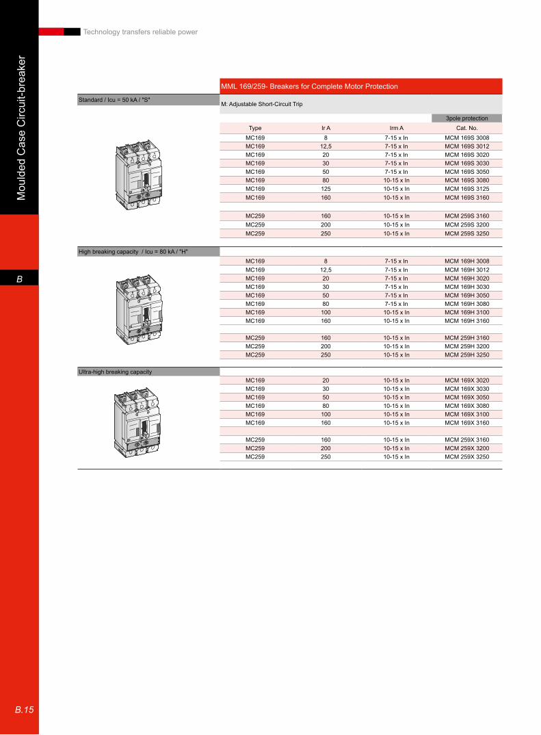
MML 169/259- Breakers for Complete Motor Protection
Standard / Icu = 50 kA / "S"M: Adjustable Short-Circuit Trip
3pole protectionType Ir A Irm A Cat. No.
MC169 8 7-15 x In MCM 169S 3008MC169 12,5 7-15 x In MCM 169S 3012MC169 20 7-15 x In MCM 169S 3020MC169 30 7-15 x In MCM 169S 3030MC169 50 7-15 x In MCM 169S 3050MC169 80 10-15 x In MCM 169S 3080MC169 125 10-15 x In MCM 169S 3125MC169 160 10-15 x In MCM 169S 3160
MC259 160 10-15 x In MCM 259S 3160MC259 200 10-15 x In MCM 259S 3200MC259 250 10-15 x In MCM 259S 3250
High breaking capacity / Icu = 80 kA / "H"MC169 8 7-15 x In MCM 169H 3008MC169 12,5 7-15 x In MCM 169H 3012MC169 20 7-15 x In MCM 169H 3020MC169 30 7-15 x In MCM 169H 3030MC169 50 7-15 x In MCM 169H 3050MC169 80 7-15 x In MCM 169H 3080MC169 100 10-15 x In MCM 169H 3100MC169 160 10-15 x In MCM 169H 3160
MC259 160 10-15 x In MCM 259H 3160MC259 200 10-15 x In MCM 259H 3200MC259 250 10-15 x In MCM 259H 3250
Ultra-high breaking capacityMC169 20 10-15 x In MCM 169X 3020MC169 30 10-15 x In MCM 169X 3030MC169 50 10-15 x In MCM 169X 3050MC169 80 10-15 x In MCM 169X 3080MC169 100 10-15 x In MCM 169X 3100MC169 160 10-15 x In MCM 169X 3160
MC259 160 10-15 x In MCM 259X 3160MC259 200 10-15 x In MCM 259X 3200MC259 250 10-15 x In MCM 259X 3250

Moulded C
ase Circuit-breaker
B
B.16
Technology transfers reliable power
MCE 169/259-Breakers for Selective Electronic Trip
Standard / Icu = 50 kA / "S"E: Selective Electronic Trip Unit Without Rating Plug
3pole 4pole(1)
Type Ir A Irm A Cat. No. Cat. No.MC169 25 2 - 13 x Ir MCE 169S 3025 MCE 169S 4025MC169 63 2 - 13 x Ir MCE 169S 3063 MCE 169S 4063MC169 125 2 - 13 x Ir MCE 169S 3125 MCE 169S 4125MC169 160 2 - 13 x Ir MCE 169S 3160 MCE 169S 4160
MC259 125 2 - 13 x Ir MCE 259S 3125 MCE 259S 4125MC259 160 2 - 13 x Ir MCE 259S 3160 MCE 259S 4160MC259 250 2 - 13 x Ir MCE 259S 3250 MCE 259S 4250
High breaking capacity / Icu = 80 kA / "H"MC169 25 2 - 13 x Ir MCE 169H 3025 MCE 169H 4025MC169 63 2 - 13 x Ir MCE 169H 3063 MCE 169H 4063MC169 125 2 - 13 x Ir MCE 169H 3125 MCE 169H 4125MC169 160 2 - 13 x Ir MCE 169H 3160 MCE 169H 4160
MC259 125 2 - 13 x Ir MCE 259H 3125 MCE 259H 4125MC259 160 2 - 13 x Ir MCE 259H 3160 MCE 259H 4160MC259 250 2 - 13 x Ir MCE 259H 3250 MCE 259H 4250
Ultra-high breaking capacity / Icu = 150 kA / "X"MC169 25 2 - 13 x Ir MCE 169X 3025 MCE 169X 4025MC169 63 2 - 13 x Ir MCE 169X 3063 MCE 169X 4063MC169 125 2 - 13 x Ir MCE 169X 3125 MCE 169X 4125MC169 160 2 - 13 x Ir MCE 169X 3160 MCE 169X 4160
MC259 125 2 - 13 x Ir MCE 259X 3125 MCE 259X 4125MC259 160 2 - 13 x Ir MCE 259X 3160 MCE 259X 4160MC259 250 2 - 13 x Ir MCE 259X 3250 MCE 259X 4250
MCE 169/259-Rating Plugs
Line protection: adjustable :Ir=0.64-1×ln
3pole protection 4pole protection(1)
Type Ir A Irm A Cat. No. Cat. No.MC169 16 RPA 13025 -016 RPA 14025 -016MC169 25 RPA 13025 -025 RPA 14025 -025MC169 40 RPA 13063 -040 RPA 14063 -040MC169 63 RPA 13063 -063 RPA 14063 -063
MC169 / 259 80 RPA 23125 -080 RPA 24125 -080MC169 / 259 100 RPA 23160 -100 RPA 24160 -100MC169 / 259 125 RPA 23125 -125 RPA 24125 -125MC169 / 259 160 RPA 23160 -160 RPA 24160 -160
MC259 160 RPA 23250 -160 RPA 24250 -160MC259 250 RPA 23250 -250 RPA 24250 -250
Switchable Line or motor protection: Ir=0.64-1×lnMC169 25 RPS 13025 -025 RPS 14025 -025MC169 63 RPS 13063 -063 RPS 14063 -063
MC169 / 259 125 RPS 23125 -125 RPS 24125 -125MC169 / 259 160 RPS 23160 -160 RPS 24160 -160
MC259 250 RPS 23250 -250 RPS 24250 -250
(1) Npole is mounted on the left side of the breaker. Please contact us if you want Npole to be mounted on the right side of the breaker(2) a complete trip unit includes an electronic trip unit and a rating plug

Mou
lded
Cas
e C
ircui
t-bre
aker
B
B.17
Technology transfers reliable power
MC 169/259-RCD Unit3pole 4pole(1)
Type Ir A Cat. No. Cat. No.MC169 220 / 440 DB3 / M91-2/6 DB4 / M91-2/6
400 / 690 DB3 / M91-4/6 DB4 / M91-4/6
MC259 220 / 440 DB3 / M92-2/6 DB4 / M92-2/6400 / 690 DB3 / M92-4/6 DB4 / M92-4/6
MC169/259 1 NO FAB AT101 NC FAB AT01
RCD base mounting
RCD base mounting
RCD alarm contact
MCM 409/639-Breakers for Complete Motor Protection
Standard / Icu = 50 kA / "S" M:with an adjustable electronic short-circuit trip unit and a rating plug
3pole protectionType Ir A Irm A Cat. No.
MC409 350 2-13 x Ir MCM 409S 3350
MC639 500 2-13 x Ir MCM 639S 3500
High breaking capacity / Icu = 80 kA / "H"MC409 350 2-13 x Ir MCM 409H 3350
MC639 500 2-13 x Ir MCM 639H 3500
Ultra-high breaking capacity / Icu = 150 kA / "X"MC409 350 2-13 x Ir MCM 409X 3350
MC639 500 2-13 x Ir MCM 639X 3500
(1) Npole is mounted on the left side of the breaker. Please contact us if you want Npole to be mounted on the right side of the breaker
Moulded C
ase Circuit-breaker
B
B.18
Technology transfers reliable power
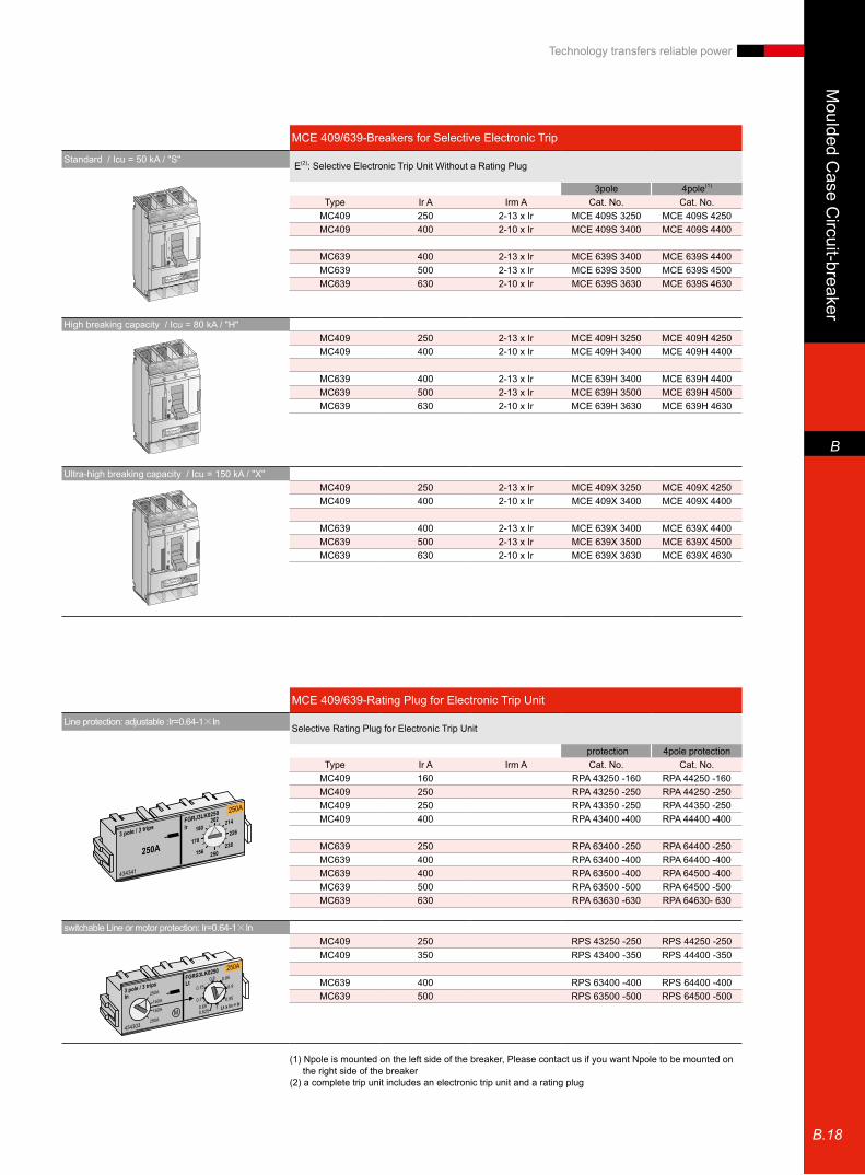
MCE 409/639-Breakers for Selective Electronic Trip
Standard / Icu = 50 kA / "S" E(2): Selective Electronic Trip Unit Without a Rating Plug
3pole 4pole(1)
Type Ir A Irm A Cat. No. Cat. No.MC409 250 2-13 x Ir MCE 409S 3250 MCE 409S 4250MC409 400 2-10 x Ir MCE 409S 3400 MCE 409S 4400
MC639 400 2-13 x Ir MCE 639S 3400 MCE 639S 4400MC639 500 2-13 x Ir MCE 639S 3500 MCE 639S 4500MC639 630 2-10 x Ir MCE 639S 3630 MCE 639S 4630
High breaking capacity / Icu = 80 kA / "H"MC409 250 2-13 x Ir MCE 409H 3250 MCE 409H 4250MC409 400 2-10 x Ir MCE 409H 3400 MCE 409H 4400
MC639 400 2-13 x Ir MCE 639H 3400 MCE 639H 4400MC639 500 2-13 x Ir MCE 639H 3500 MCE 639H 4500MC639 630 2-10 x Ir MCE 639H 3630 MCE 639H 4630
Ultra-high breaking capacity / Icu = 150 kA / "X"MC409 250 2-13 x Ir MCE 409X 3250 MCE 409X 4250MC409 400 2-10 x Ir MCE 409X 3400 MCE 409X 4400
MC639 400 2-13 x Ir MCE 639X 3400 MCE 639X 4400MC639 500 2-13 x Ir MCE 639X 3500 MCE 639X 4500MC639 630 2-10 x Ir MCE 639X 3630 MCE 639X 4630
(1) Npole is mounted on the left side of the breaker, Please contact us if you want Npole to be mounted on the right side of the breaker(2) a complete trip unit includes an electronic trip unit and a rating plug
MCE 409/639-Rating Plug for Electronic Trip Unit
Line protection: adjustable :Ir=0.64-1×lnSelective Rating Plug for Electronic Trip Unit
protection 4pole protectionType Ir A Irm A Cat. No. Cat. No.
MC409 160 RPA 43250 -160 RPA 44250 -160MC409 250 RPA 43250 -250 RPA 44250 -250MC409 250 RPA 43350 -250 RPA 44350 -250MC409 400 RPA 43400 -400 RPA 44400 -400
MC639 250 RPA 63400 -250 RPA 64400 -250MC639 400 RPA 63400 -400 RPA 64400 -400MC639 400 RPA 63500 -400 RPA 64500 -400MC639 500 RPA 63500 -500 RPA 64500 -500MC639 630 RPA 63630 -630 RPA 64630- 630
switchable Line or motor protection: Ir=0.64-1×lnMC409 250 RPS 43250 -250 RPS 44250 -250MC409 350 RPS 43400 -350 RPS 44400 -350
MC639 400 RPS 63400 -400 RPS 64400 -400MC639 500 RPS 63500 -500 RPS 64500 -500
Mou
lded
Cas
e C
ircui
t-bre
aker
B
B.19
Technology transfers reliable power
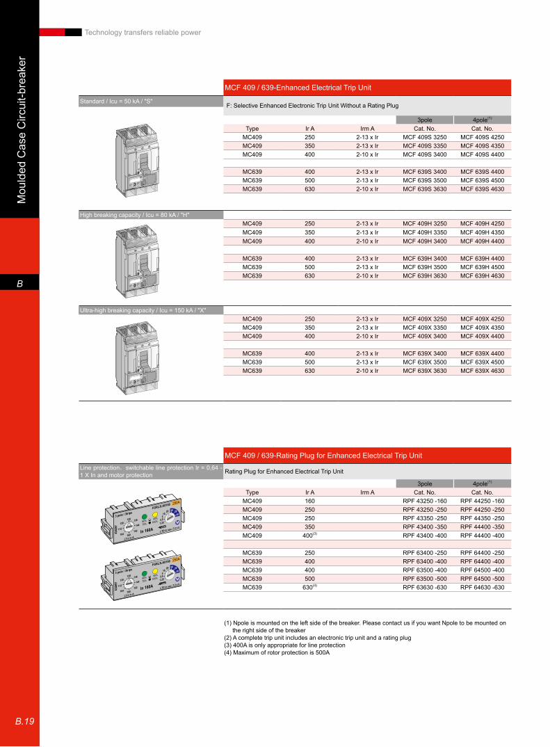
(1) Npole is mounted on the left side of the breaker. Please contact us if you want Npole to be mounted on the right side of the breaker(2) A complete trip unit includes an electronic trip unit and a rating plug(3) 400A is only appropriate for line protection(4) Maximum of rotor protection is 500A
MCF 409 / 639-Enhanced Electrical Trip Unit
Standard / Icu = 50 kA / "S" F: Selective Enhanced Electronic Trip Unit Without a Rating Plug
3pole 4pole(1)
Type Ir A Irm A Cat. No. Cat. No.MC409 250 2-13 x Ir MCF 409S 3250 MCF 409S 4250MC409 350 2-13 x Ir MCF 409S 3350 MCF 409S 4350MC409 400 2-10 x Ir MCF 409S 3400 MCF 409S 4400
MC639 400 2-13 x Ir MCF 639S 3400 MCF 639S 4400MC639 500 2-13 x Ir MCF 639S 3500 MCF 639S 4500MC639 630 2-10 x Ir MCF 639S 3630 MCF 639S 4630
High breaking capacity / Icu = 80 kA / "H" MC409 250 2-13 x Ir MCF 409H 3250 MCF 409H 4250MC409 350 2-13 x Ir MCF 409H 3350 MCF 409H 4350MC409 400 2-10 x Ir MCF 409H 3400 MCF 409H 4400
MC639 400 2-13 x Ir MCF 639H 3400 MCF 639H 4400MC639 500 2-13 x Ir MCF 639H 3500 MCF 639H 4500MC639 630 2-10 x Ir MCF 639H 3630 MCF 639H 4630
Ultra-high breaking capacity / Icu = 150 kA / "X"MC409 250 2-13 x Ir MCF 409X 3250 MCF 409X 4250MC409 350 2-13 x Ir MCF 409X 3350 MCF 409X 4350MC409 400 2-10 x Ir MCF 409X 3400 MCF 409X 4400
MC639 400 2-13 x Ir MCF 639X 3400 MCF 639X 4400MC639 500 2-13 x Ir MCF 639X 3500 MCF 639X 4500MC639 630 2-10 x Ir MCF 639X 3630 MCF 639X 4630
MCF 409 / 639-Rating Plug for Enhanced Electrical Trip UnitLine protection,switchable line protection Ir = 0,64 - 1 X In and motor protection Rating Plug for Enhanced Electrical Trip Unit
3pole 4pole(1)
Type Ir A Irm A Cat. No. Cat. No.MC409 160 RPF 43250 -160 RPF 44250 -160MC409 250 RPF 43250 -250 RPF 44250 -250MC409 250 RPF 43350 -250 RPF 44350 -250MC409 350 RPF 43400 -350 RPF 44400 -350MC409 400(3) RPF 43400 -400 RPF 44400 -400
MC639 250 RPF 63400 -250 RPF 64400 -250MC639 400 RPF 63400 -400 RPF 64400 -400MC639 400 RPF 63500 -400 RPF 64500 -400MC639 500 RPF 63500 -500 RPF 64500 -500MC639 630(4) RPF 63630 -630 RPF 64630 -630

Moulded C
ase Circuit-breaker
B
B.20
Technology transfers reliable power
MC 409 / 639-Current Residue Protection Unit3pole 4pole(1)
Type Rated Voltage V / AC Cat. No. Cat. No.MC409/639 220 / 440 DB3 / M96-2/6 DB4 / M96-2/6
400 / 690 DB3 / M96-4/6 DB4 / M96-4/6
MC409/639 1 NO FAB AT101 NC FAB AT01
(1) Npole is mounted on the left side of the breaker. Please contact us if you want Npole to be mounted on the right side of the breaker
MM 169, MC 169 / 259 / 409 / 639 accessory
internal add-on
MM 169 MC 169 / 259 MC 409 / 639Cat. No. Cat. No. Cat. No. Cat. No.
Contact of right-side mounting / 1NO FAS10R FAS10R FAS10R 1NC FAS01R FAS01R FAS01RContact of right-side mounting / 1NC FAS10L FAS10L FAS10L
1NO FAS01L FAS01L FAS01L
Alarm contact (electrical trip unit) / 1NC - FABAT10 FABAT10 1NO - FABAT01 FABAT01
Alarm contact (thermal and magnetic trip unit) 1NO FABAT10 FEBAT10 -
1NC FABAT01 FEBAT01 -
RCD alarm contact / 1NO FABAT10 FABAT10 FABAT10 1NC FABAT01 FABAT01 FABAT01
Mechanical/alarm contact 1CO FDBAM11 - - 1NO - FABAM10 FABAM10 1NC - FABAM01 FABAM01
Shunt 12 V DC FASHTB FASHTB FASHTB24 V AC/DC FASHTD FASHTD FASHTD48 V AC/DC FASHTF FASHTF FASHTF110/130 V AC/DC FASHTJ FASHTJ FASHTJ220/240 V AC 250 V DC FASHTN FASHTN FASHTN400/480 V AC FASHTU FASHTU FASHTU
Under voltage 12 V DC -24 V AC/DC FAUVRD FAUVRD FAUVRD48 V AC/DC FAUVRF FAUVRF FAUVRF110/130 V AC/DC FAUVRJ FAUVRJ FAUVRJ220/240 V AC 250 V DC FAUVRN FAUVRN FAUVRN
400/480 V AC FAUVRU FAUVRU FAUVRU
Under voltage with time delay 12 V DC - - FAUVDB220/240 V AC FAUVDN FAUVDN FAUVDN
Motor operating unit 24 V AC / DC F/MM9-24U F/M92-24U F/M96-24U48 V AC / DC F/MM9-48U F/M92-48U F/M96-48U60 V AC / DC F/MM9-60U F/M92-60U F/M96-60U110 V AC / DC F/MM9-110U F/M92-110U F/M96-110U220/250 V AC / DC F/MM9-220U F/M92-220U F/M96-220U400/440 V AC F/MM9-400A F/M92-400A F/M96-400A
Padlock for electrical unit Ronis (2) FD1 BRE FE1 BRE FG1 BREPadlock for electrical unit Profalux(2) FD1 BPE FE1 BPE FG1 BPE
(2) Keys included
Contact
Trip unit
Operation unit
Bottom mounting
Alarm contact
Mou
lded
Cas
e C
ircui
t-bre
aker
B
B.21
Technology transfers reliable power
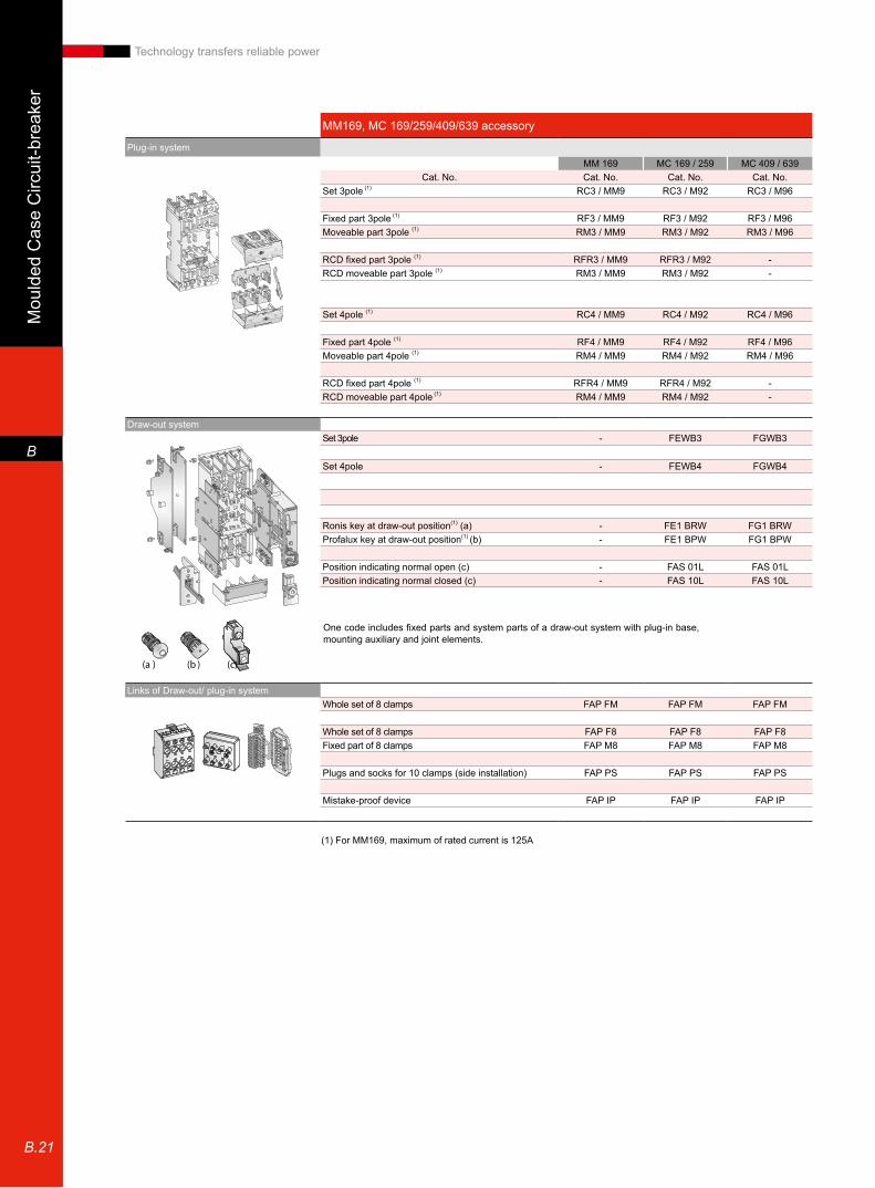
MM169, MC 169/259/409/639 accessory
Plug-in system
MM 169 MC 169 / 259 MC 409 / 639Cat. No. Cat. No. Cat. No. Cat. No.
Set 3pole (1) RC3 / MM9 RC3 / M92 RC3 / M96
Fixed part 3pole (1) RF3 / MM9 RF3 / M92 RF3 / M96Moveable part 3pole (1) RM3 / MM9 RM3 / M92 RM3 / M96
RCD fixed part 3pole (1) RFR3 / MM9 RFR3 / M92 -RCD moveable part 3pole (1) RM3 / MM9 RM3 / M92 -
Set 4pole (1) RC4 / MM9 RC4 / M92 RC4 / M96
Fixed part 4pole (1) RF4 / MM9 RF4 / M92 RF4 / M96Moveable part 4pole (1) RM4 / MM9 RM4 / M92 RM4 / M96
RCD fixed part 4pole (1) RFR4 / MM9 RFR4 / M92 -RCD moveable part 4pole (1) RM4 / MM9 RM4 / M92 -
Draw-out systemSet 3pole - FEWB3 FGWB3
Set 4pole - FEWB4 FGWB4
Ronis key at draw-out position(1) (a) - FE1 BRW FG1 BRWProfalux key at draw-out position(1) (b) - FE1 BPW FG1 BPW
Position indicating normal open (c) - FAS 01L FAS 01LPosition indicating normal closed (c) - FAS 10L FAS 10L
Links of Draw-out/ plug-in systemWhole set of 8 clamps FAP FM FAP FM FAP FM
Whole set of 8 clamps FAP F8 FAP F8 FAP F8Fixed part of 8 clamps FAP M8 FAP M8 FAP M8
Plugs and socks for 10 clamps (side installation) FAP PS FAP PS FAP PS
Mistake-proof device FAP IP FAP IP FAP IP
(1) For MM169, maximum of rated current is 125A
(a ) (b ) (c)
One code includes fixed parts and system parts of a draw-out system with plug-in base, mounting auxiliary and joint elements.
Moulded C
ase Circuit-breaker
B
B.22
Technology transfers reliable power
Curve
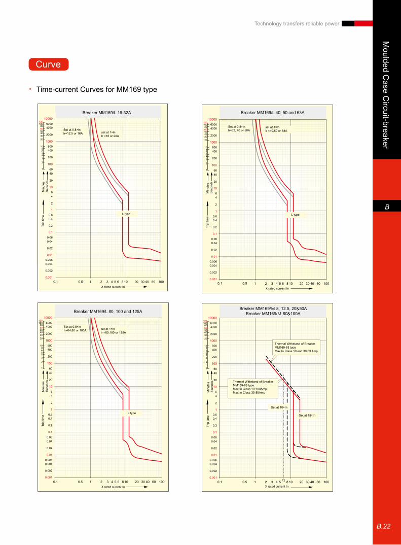
Time-current Curves for MM169 type •
Breaker MM169/L 16-32A
L type
Set at 0.8×lnIr=12.5 or 16A set at 1×ln
Ir =16 or 20A
X rated current In
Trip
tim
eM
inut
esS
econ
ds
L type L type L type
7.2
L type L type L type
7.2
L type L type L type
7.2
Mou
lded
Cas
e C
ircui
t-bre
aker
B
B.23
Technology transfers reliable power
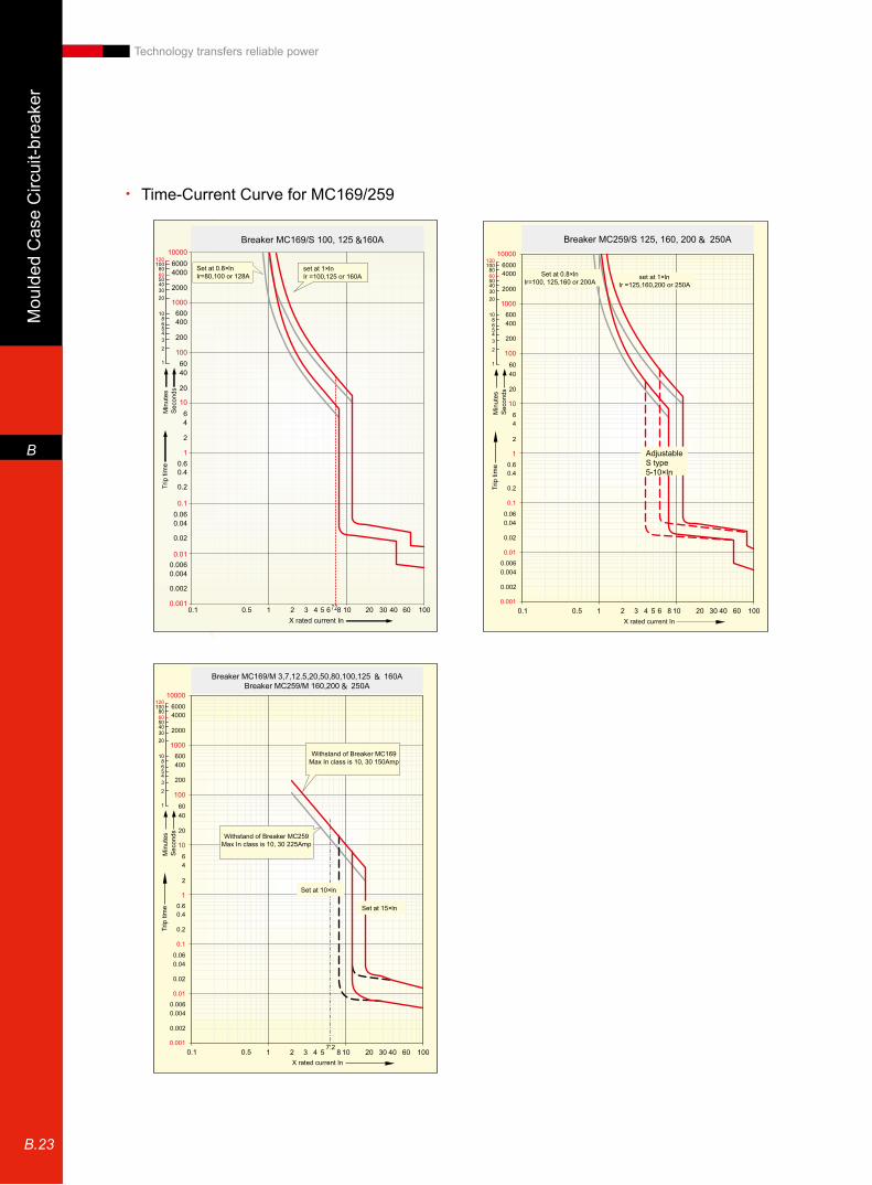
Time-Current Curve for MC169/259 •
Set at 0.8×lnIr=64,80,100 or 128A
set at 1×lnIr =80,100,125 or 160A
X rated current In
Trip
tim
eM
inut
esS
econ
dsTr
ip ti
me
Min
utes
Sec
onds
Trip
tim
eM
inut
esS
econ
ds0.001
0.01
0.1
0.2
0.40.6
0.002
0.0040.006
0.02
0.040.06
1
10
100
1000
10000120
60
10080
50403020
1086543
2
1
120
60
10080
50403020
1086543
2
1
2
46
20
4060
200
400600
2000
40006000
0.001
0.01
0.1
0.2
0.40.6
0.002
0.0040.006
0.02
0.040.06
1
10
100
1000
10000
2
46
20
4060
200
400600
2000
40006000
0.1 0.5 1 2 3 4 5 6 7.28 10 20 30 40 60 100
0.1 0.5 1 2 3X rated current In
4 5 6 7.28 10 20 30 40 60 100
Breaker MC169/S 100, 125 160A Breaker MC259/S 125, 160, 200 250A
Breaker MC169/M 3,7,12.5,20,50,80,100,125 160ABreaker MC259/M 160,200 250A
Set at 0.8×lnIr=100, 125,160 or 200A
set at 1×lnIr =125,160,200 or 250A
Withstand of Breaker MC169Max In class is 10, 30 150Amp
Withstand of Breaker MC259Max In class is 10, 30 225Amp
X rated current In
X rated current In
Trip
tim
eM
inut
esS
econ
ds
Trip
tim
eM
inut
esS
econ
ds
Set at 15×ln
Set at 10×ln
Breaker FE250 / GTM 160, 200 & 250A
Set at 0.8×InIr=128, 200 or 250A Set at 1×In
Ir=160, 200 or 250A
Adjustable GTM type3-5×In Adjustable
S type5-10×In
X rated current In
Trip
tim
eM
inut
esS
econ
ds
0.002
0.0040.006
0.001
0.01
0.1
0.02
0.040.06
0.2
0.40.6
0.50.1
0.002
0.0040.006
0.001
0.01
0.1
0.02
0.040.06
0.2
0.40.6
0.57.2
0.1
0.002
0.0040.006
0.001
0.01
0.1
0.02
0.040.06
0.2
0.40.6
0.50.1
Breaker MC259/S 125, 160, 200 250A
Breaker MC169/M 3,7,12.5,20,50,80,100,125 160ABreaker MC259/M 160,200 250A
Set at 0.8×lnIr=100, 125,160 or 200A
set at 1×lnIr =125,160,200 or 250A
Withstand of Breaker MC169Max In class is 10, 30 150Amp
Withstand of Breaker MC259Max In class is 10, 30 225Amp
X rated current In
X rated current In
Trip
tim
eM
inut
esS
econ
ds
Trip
tim
eM
inut
esS
econ
ds
Set at 15×ln
Set at 10×ln
Breaker FE250 / GTM 160, 200 & 250A
Set at 0.8×InIr=128, 200 or 250A Set at 1×In
Ir=160, 200 or 250A
Adjustable GTM type3-5×In Adjustable
S type5-10×In
X rated current In
Trip
tim
eM
inut
esS
econ
ds
0.002
0.0040.006
0.001
0.01
0.1
0.02
0.040.06
0.2
0.40.6
0.50.1
0.002
0.0040.006
0.001
0.01
0.1
0.02
0.040.06
0.2
0.40.6
0.57.2
0.1
0.002
0.0040.006
0.001
0.01
0.1
0.02
0.040.06
0.2
0.40.6
0.50.1
Moulded C
ase Circuit-breaker
B
B.24
Technology transfers reliable power
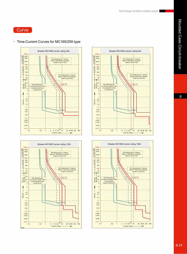
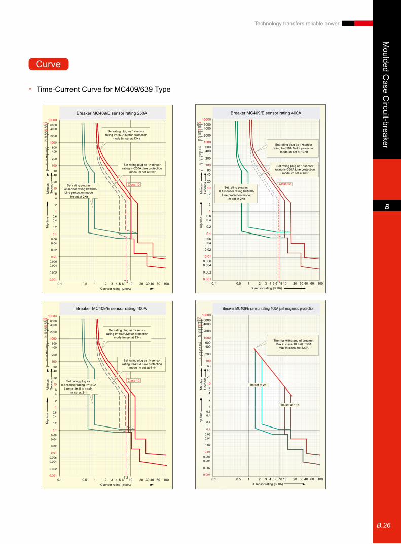
Set rating plug as 0.4×sensor rating Ir=10A
Line protection mode Im set at 2×Ir
Set rating plug as 0.4×sensor rating Ir=50A
Line protection mode Im set at 2×Ir
Set rating plug as 0.4×sensor rating Ir=25A
Line protection mode Im set at 2×Ir
Set rating plug as 1×sensor rating Ir=25A Line protection
mode Im set at 6×Ir
Set rating plug as 1×sensor rating Ir=63A Line protection
mode Im set at 6×Ir
Set rating plug as 1×sensor rating Ir=25A Motor protection
mode Im set at 13×Ir
Set rating plug as 1×sensor rating Ir=125A Motor protection
mode Im set at 13×Ir
Set rating plug as 1×sensor rating Ir=160A Motor protection
mode Im set at 13×Ir
Set rating plug as 1×sensor rating Ir=160A Line protection
mode Im set at 6×Ir
Set rating plug as 1×sensor rating Ir=63A Motor protection
mode Im set at 13×Ir
Breaker MC169/E sensor rating 25A
Breaker MC169/E sensor rating 125A Breaker MC169/E sensor rating 160A
Breaker MC169/E sensor rating 63A
X sensor rating
X sensor rating X sensor rating
X sensor rating
Trip
tim
eM
inut
esS
econ
dsTr
ip ti
me
Min
utes
Sec
onds
Trip
tim
eM
inut
esS
econ
dsTr
ip ti
me
Min
utes
Sec
onds
Set rating plug as 1×sensor rating Ir=125A Line protection
mode Im set at 6×Ir
Set rating plug as 0.4×sensor rating Ir=64A
Line protection mode Im set at 2×Ir
Class 10 Class 10
Class 10 Class 10
0.002
0.0040.006
0.001
0.01
0.1
0.02
0.040.06
0.2
0.40.6
0.002
0.0040.006
0.001
0.01
0.1
0.02
0.040.06
0.2
0.40.6
0.57.2 7.2
7.2 7.2
0.1
0.002
0.0040.006
0.001
0.01
0.1
0.02
0.040.06
0.2
0.40.6
0.002
0.0040.006
0.001
0.01
0.1
0.02
0.040.06
0.2
0.40.6
0.50.1 0.50.1
0.50.1
Time-Current Curves for MC169/259 type •
Curve

Mou
lded
Cas
e C
ircui
t-bre
aker
B
B.25
Technology transfers reliable power
Class 10
Class 10
Class 10Set rating plug as 0.4×sensor rating Ir=50A
Line protection mode Im set at 2×Ir
Set rating plug as 0.4×sensor rating Ir=100A
Line protection mode Im set at 2×Ir
Set rating plug as 0.4×sensor rating Ir=64A
Line protection mode Im set at 2×Ir
Set rating plug as 1×sensor rating Ir=125A Line protection
mode Im set at 6×Ir
Set rating plug as 1×sensor rating Ir=250A Line protection
mode Im set at 6×Ir
Set rating plug as 1×sensor rating Ir=160A Line protection
mode Im set at 6×Ir
Set rating plug as 1×sensor rating Ir=125A Motor protection
mode Im set at 13×Ir
Set rating plug as 1×sensor rating Ir=250A Motor protection
mode Im set at 13×Ir
Set rating plug as 1×sensor rating Ir=160A Motor protection
mode Im set at 13×Ir
Breaker MC259/E sensor rating 125A
Breaker MC259/E sensor rating 250A
Breaker MC259/E sensor rating 160A
X sensor rating
X sensor rating
X sensor rating
Trip
tim
eM
inut
esS
econ
dsTr
ip ti
me
Min
utes
Sec
onds
Trip
tim
eM
inut
esS
econ
ds
0.002
0.0040.006
0.001
0.01
0.1
0.02
0.040.06
0.2
0.40.6
0.002
0.0040.006
0.001
0.01
0.1
0.02
0.040.06
0.2
0.40.6
0.002
0.0040.006
0.001
0.01
0.1
0.02
0.040.06
0.2
0.40.6
0.57.2
7.2
7.20.1
0.50.1
0.50.1
Moulded C
ase Circuit-breaker
B
B.26
Technology transfers reliable power
Time-Current Curve for MC409/639 Type •
1000060004000
2000
600400
1000
100
200
6040
20
64
2
10
1
0.1
0.5 1 2 3 4 5 6 8 10 20 30 40 60 100
10080
50403020
1086543
2
1
120
60
7.2
1000060004000
2000
600400
1000
100
200
6040
20
64
2
10
1
0.1
0.60.4
0.2
0.060.04
0.02
0.010.0060.004
0.002
0.0010.1 0.5 1 2 3 4 5 6 8 10 20 30 40 60 100
10080
50403020
1086543
2
1
120
60
Set rating plug as 0.4×sensor rating Ir=100A
Line protection mode Im set at 2×Ir
Set rating plug as 0.4×sensor rating Ir=160A
Line protection mode Im set at 2×Ir
Set rating plug as 1×sensor rating Ir=250A Line protection
mode Im set at 6×Ir
Set rating plug as 1×sensor rating Ir=350A Line protection
mode Im set at 6×Ir
Set rating plug as 1×sensor rating Ir=250A Motor protection
mode Im set at 13×Ir
Set rating plug as 1×sensor rating Ir=350A Motor protection
mode Im set at 13×Ir
Thermal withstand of breaker:Max in class 10 &20: 350A
Max in class 30: 320A
Breaker MC409/E sensor rating 250A
Breaker MC409/E sensor rating 400A just magnetic protection
Breaker MC409/E sensor rating 400A
X sensor rating
X sensor rating
X sensor rating
Trip
tim
eM
inut
esS
econ
ds
Trip
tim
eM
inut
esS
econ
dsTr
ip ti
me
Min
utes
Sec
ondsSet rating plug as
0.4×sensor rating Ir=160ALine protection mode
Im set at 2×Ir
Set rating plug as 1×sensor rating Ir=400A Line protection
mode Im set at 6×Ir
Set rating plug as 1×sensor rating Ir=400A Motor protection
mode Im set at 13×Ir
Breaker MC409/E sensor rating 400A
X sensor rating
Trip
tim
eM
inut
esS
econ
ds
Im set at 2×
Im set at 13×
Class 10 Class 10
Class 10
0.002
0.0040.006
0.001
0.01
0.1
0.02
0.040.06
0.2
0.40.6
0.002
0.0040.006
0.001
0.01
0.1
0.02
0.040.06
0.2
0.40.6
0.002
0.0040.006
0.001
0.01
0.1
0.02
0.040.06
0.2
0.40.6
0.57.2
7.2
0.1
0.50.1
7.2
Curve
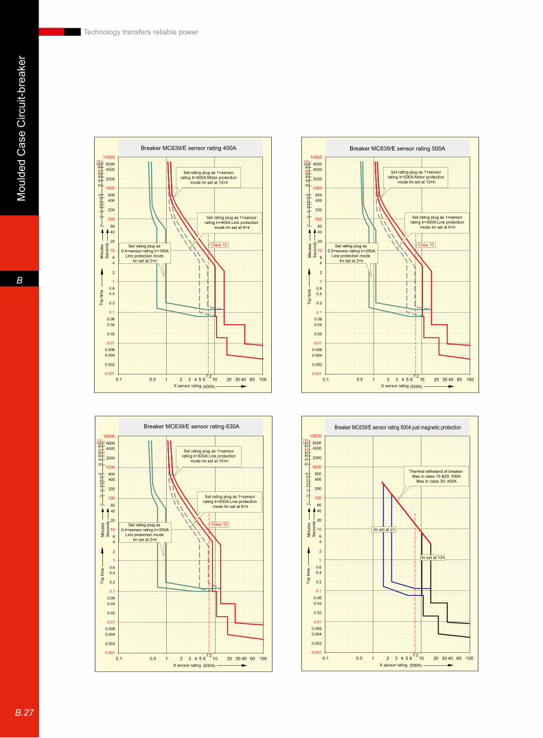
Mou
lded
Cas
e C
ircui
t-bre
aker
B
B.27
Technology transfers reliable power
Set rating plug as 0.4×sensor rating Ir=160A
Line protection mode Im set at 2×Ir
Set rating plug as 0.4×sensor rating Ir=250A
Line protection mode Im set at 2×Ir
Set rating plug as 0.5×sensor rating Ir=250A
Line protection mode Im set at 2×Ir
Set rating plug as 1×sensor rating Ir=400A Line protection
mode Im set at 6×Ir
Set rating plug as 1×sensor rating Ir=630A Line protection
mode Im set at 6×Ir
Set rating plug as 1×sensor rating Ir=630A Line protection
mode Im set at 10×Ir
Set rating plug as 1×sensor rating Ir=500A Line protection
mode Im set at 6×Ir
Thermal withstand of breaker:Max in class 10 &20: 500A
Max in class 30: 450A
Set rating plug as 1×sensor rating Ir=400A Motor protection
mode Im set at 13×Ir
Set rating plug as 1×sensor rating Ir=500A Motor protection
mode Im set at 13×Ir
Breaker MC639/E sensor rating 400A
Breaker MC639/E sensor rating 630A Breaker MC639/E sensor rating 500A just magnetic protection
Breaker MC639/E sensor rating 500A
X sensor rating
X sensor rating X sensor rating
X sensor rating
Trip
tim
eM
inut
esS
econ
dsTr
ip ti
me
Min
utes
Sec
onds
Trip
tim
eM
inut
esS
econ
dsTr
ip ti
me
Min
utes
Sec
onds
Im set at 2×
Im set at 13×
Class 10
Class 10
Class 10
0.002
0.0040.006
0.001
0.01
0.1
0.02
0.040.06
0.2
0.40.6
0.002
0.0040.006
0.001
0.01
0.1
0.02
0.040.06
0.2
0.40.6
0.002
0.0040.006
0.001
0.01
0.1
0.02
0.040.06
0.2
0.40.6
0.002
0.0040.006
0.001
0.01
0.1
0.02
0.040.06
0.2
0.40.6
0.57.2 7.2
7.2 7.2
0.1 0.50.1
0.50.1 0.50.1
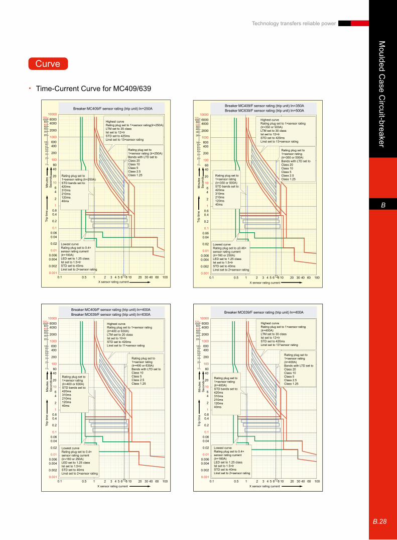
Moulded C
ase Circuit-breaker
B
B.28
Technology transfers reliable power
1000060004000
2000
600400
1000
100
200
6040
20
64
2
10
1
0.1
0.60.4
0.2
0.060.04
0.02
0.010.0060.004
0.002
0.0010.1 0.5 1 2 3 4 5 6 8 10 20 30 40 60 100
10080
50403020
1086543
2
1
120
60
7.2
1000060004000
2000
600400
1000
100
200
6040
20
64
2
10
1
0.1
0.60.4
0.2
0.060.04
0.02
0.010.0060.004
0.002
0.0010.1 0.5 1 2 3 4 5 6 8 10 20 30 40 60 100
10080
50403020
1086543
2
1
120
60
7.2
1000060004000
2000
600400
1000
100
200
6040
20
64
2
10
1
0.1
0.60.4
0.2
0.060.04
0.02
0.010.0060.004
0.002
0.0010.1 0.5 1 2 3 4 5 6 8 10 20 30 40 60 100
10080
50403020
1086543
2
1
120
60
7.2
1000060004000
2000
600400
1000
100
200
6040
20
64
2
10
1
0.1
0.60.4
0.2
0.060.04
0.02
0.010.0060.004
0.002
0.0010.1 0.5 1 2 3 4 5 6 8 10 20 30 40 60 100
10080
50403020
1086543
2
1
120
60
7.2
Breaker MC409/F sensor rating (trip unit) In=250ABreaker MC409/F sensor rating (trip unit) In=350ABreaker MC639/F sensor rating (trip unit) In=500A
Breaker MC409/F sensor rating (trip unit) In=400ABreaker MC639/F sensor rating (trip unit) In=630A Breaker MC639/F sensor rating (trip unit) In=400A
Highest curveRating plug set to 1×sensor rating(Ir=250A)LTM set to 35 classIst set to 12×IrSTD set to 425msLinst set to 13×sensor rating
Highest curveRating plug set to 1×sensor rating(Ir=400 or 630A)LTM set to 20 classIst set to 10×IrSTD set to 420msLinst set to 11×sensor rating
Highest curveRating plug set to 1×sensor rating(Ir=350 or 500A)LTM set to 30 classIst set to 12×IrSTD set to 420msLinst set to 13×sensor rating
Highest curveRating plug set to 1×sensor rating(Ir=400A)LTM set to 30 classIst set to 12×IrSTD set to 420msLinst set to 13*sensor rating
Rating plug set to 1×sensor rating (Ir=250A)Bands with LTD set toClass 20Class 10Class 5Class 2.5Class 1.25
Rating plug set to 1×sensor rating (Ir=400 or 630A)Bands with LTD set toClass 10Class 5Class 2.5Class 1.25
Rating plug set to 1×sensor rating (Ir=350 or 500A)Bands with LTD set toClass 20Class 10Class 5Class 2.5Class 1.25
Rating plug set to 1×sensor rating (Ir=400A)Bands with LTD set toClass 20Class 10Class 5Class 2.5Class 1.25
Rating plug set to 1×sensor rating (Ir=250A)STD bands set to:420ms310ms210ms120ms40ms
Rating plug set to 1×sensor rating(Ir=400 or 630A)STD bands set to:420ms310ms210ms120ms40ms
Rating plug set to 1×sensor rating (Ir=350 or 500A)STD bands set to:420ms310ms210ms120ms40ms
Rating plug set to 1×sensor rating (Ir=400A)STD bands set to:420ms310ms210ms120ms40ms
Lowest curveRating plug set to 0.4×sensor rating current (Ir=100A)LED set to 1.25 classIst set to 1.5×IrSTD set to 45msLinst set to 2×sensor rating
Lowest curveRating plug set to 0.4×sensor rating current (Ir=160 or 250A)LED set to 1.25 classIst set to 1.5×IrSTD set to 40msLinst set to 2×sensor rating
Lowest curveRating plug set to ±0.46×sensor rating current(Ir=160 or 250A)LED set to 1.25 classIst set to 1.5×IrSTD set to 40msLinst set to 2×sensor rating
Lowest curveRating plug set to 0.4×sensor rating current(Ir=160A)LED set to 1.25 classIst set to 1.5×IrSTD set to 40msLinst set to 2×sensor rating
X sensor rating current
X sensor rating current X sensor rating current
X sensor rating current
Trip
tim
eM
inut
esS
econ
dsTr
ip ti
me
Min
utes
Sec
onds
Trip
tim
eM
inut
esS
econ
dsTr
ip ti
me
Min
utes
Sec
onds
Time-Current Curve for MC409/639 •
Curve

Mou
lded
Cas
e C
ircui
t-bre
aker
B
B.29
Technology transfers reliable power
100
60
40
20
1
2
10
6
4
2
0.4
0.6
1
0.2
0.1
0.06
0.04
0.02
0.011 2 3 4 5 6 10 207.2 30 40 50 60 100 0.1 0.2 0.4 0.6 0.8 1 2
0.1
0.2
0.3
0.4
0.5
0.6
0.70.80.9
1
2
3
4
5
6
789
10
3 4 5 6 7 8 10
1000
100
600
400
200
108
654
3
2
1 60
40
60
10
6
4
2
1
0.1
0.6
0.4
0.2
0.1 0.2 0.4 0.6 1 2 3 4 6 10 20 30 40 60 100
1000
100
600
400
200
108
6543
2
1 60
40
60
10
6
4
2
1
0.1
0.6
0.4
0.2
0.1 0.2 0.4 0.6 1 2 3 4 6 10 20 30 40 60 100
Breaker MC409/F trip unit In=400A I2T ON Breaker MC409/MC639 ground fault(GF)
Breaker MC409/639/F shedding module R channel 1 Breaker MC409/639/F shedding module R channel 2
ST set to 1.5× I set to 1.2× STD set to 420ms I2t ON
ST set to 10×I set to1.2× STD set to 40msI2t ON
R channel bandChannel 1- set at 1×IrBands with LTD set toClass 30Class 20Class 10Class 5Class 2.5Class 1.25
R channel bandChannel 1- set at 1×IrBands with LTD set toClass 30Class 20Class 10Class 5Class 2.5Class 1.25
ST set to 10×STD set to 410ms
ST set to 10×STD set to 320ms
STD bands set to:420ms,310ms,210ms,125ms or 40msI2T ON
GF current value adjustable 0.2 to 1×sensor rating lowest band-green GF=0.2×Ir GFD=40msI2t OFF-continuous lineI2t ON- dotted line
Partial depiction of other GFD bands set at 120, 210 or 310 msI2t OFF
X sensor rating current
X sensor rating current X sensor rating current
X sensor rating current
Trip
tim
eS
econ
ds
Trip
tim
eM
inut
esS
econ
ds
Trip
tim
eM
inut
esS
econ
ds
Trip
tim
eM
inut
esS
econ
ds

Miniature C
ircuit Breaker
C
C.1
Technology transfers reliable power
MCB's series E90
■ Excellent performance meets requirements of clients from different industries.
■ Highest 3 level nominal current
■ Human oriented design, safe and reliable
Characteristics
When short-circuit occurs, the minimum thermal effects of cable and breaking point will reduce the influence to breaker and improve the electrical endurance of the breaker and the continuity supply of power
1 level current limit: I2t allow a half-sine energy 2 level current limit: I2t allow 1/3 of a half-sine energy3 level current limit: I2t allow 1/10 of a half-sine energy
padLock to prevent mistaken operation
IP 20
4.5 Nmseal
E90
0
3 2 1
i
t5 10(ms)
B
(A)
E90 1,1+N,2,3,3+N,4 yes B 6
6
6 10
10
10 20
20
20
6-63
0.5-63
0.5-63
C
D
yes
yes
E90SUC 1,2 6
6 10
106-32
0.5-32C
Byes
yes
B:3-5In
C:5-10In
D:10-20In
IEC60898
IEC60947-2
NEMA AB1
Series application short-circuit breaking capacity(kA)
No. of poles Accessory Trip class
rated current
domestic
commercial
industrial

Min
iatu
re C
ircui
t Bre
aker
C
C.2
Technology transfers reliable power
Performance
E90 E90S UC
Standard IEC60898/GB 10963、IEC60947/GB 14048
Trip characteristics B,C,D B,C
Nominal current 3 3
No. of poles 1/2/3/4,1+N,3+N 1/2
Calibration temperature ℃ 30 30
Operating temperature ℃ -25~+55 -25~+55
Storage temperature ℃ -55~+55 -55~+55
Rated current A B:6-63, C/D:0.5~63 B:6-63, C:0.5~63
Rated voltage
AC
1P V 240/415 240/415
1P+N V 240 -
2P V 415 415
3P/3P+N/4P V 415 -
DC1P V DC 48 220
2P (in series) V DC 110 440
Rated insulation voltagepollution degree 2 V 500 500
pollution degree 3 V 440 440
Impulse withstand test voltage kV 6 6
Frequency Hz 50/60 50/60
Isolation application yes yes
Breaking capacity
IEC60898 1P(230/400V) kA 6 6(1)(220VDC)
1P+N(230V) kA 6 -
2P(230/400V) kA 6 6(2)(440VDC)
3P/3P+N/4P (230/400V) kA 6
IEC60947-2 1P(127V) kA 20 -
1P(240V) kA 10 10
1P(415V) kA 3 -
1P+N/2P(127V) kA - -
1P+N/2P(240V) kA 20 -
2P(415V) kA 10 10
3P,4P(240V) kA 20 -
3P,4P(415V) kA 10 -
3P,4P(440V) kA 6 -
Mechanical endurance 次 20000 20000
Electrical endurance 次 10000 1000
Incoming up or bottom yes yes
Add-on devicesAuxiliary contacts Alarm
contacts Undervoltage release Shunt trip
Auxiliary contacts Alarm contacts Undervoltage release
Shunt trip
Terminal capacity mm2 35 35
Dimension (H*D*W)86*68*W mm/mod. 18 18
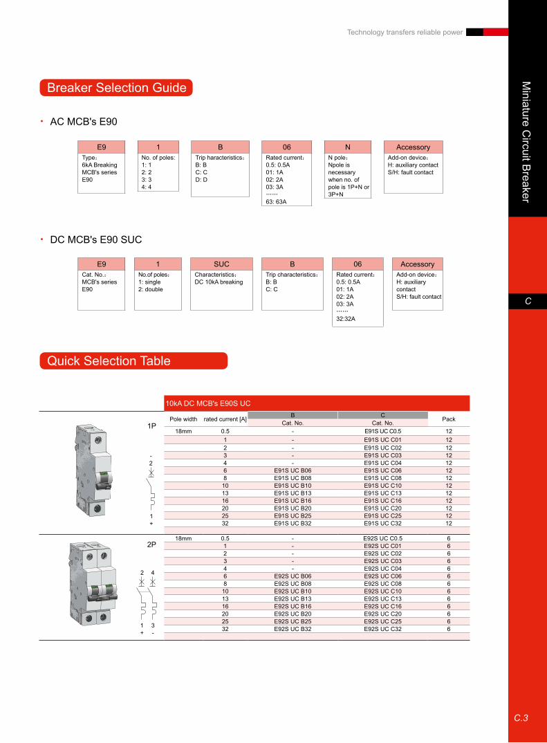
Miniature C
ircuit Breaker
C
C.3
Technology transfers reliable power
Breaker Selection Guide
Quick Selection Table
10kA DC MCB's E90S UC
Pole width rated current [A] B C PackCat. No. Cat. No.18mm 0.5 - E91S UC C0.5 12
1 - E91S UC C01 122 - E91S UC C02 123 - E91S UC C03 124 - E91S UC C04 126 E91S UC B06 E91S UC C06 128 E91S UC B08 E91S UC C08 12
10 E91S UC B10 E91S UC C10 1213 E91S UC B13 E91S UC C13 1216 E91S UC B16 E91S UC C16 1220 E91S UC B20 E91S UC C20 1225 E91S UC B25 E91S UC C25 1232 E91S UC B32 E91S UC C32 12
18mm 0.5 - E92S UC C0.5 61 - E92S UC C01 62 - E92S UC C02 63 - E92S UC C03 64 - E92S UC C04 66 E92S UC B06 E92S UC C06 68 E92S UC B08 E92S UC C08 6
10 E92S UC B10 E92S UC C10 613 E92S UC B13 E92S UC C13 616 E92S UC B16 E92S UC C16 620 E92S UC B20 E92S UC C20 625 E92S UC B25 E92S UC C25 632 E92S UC B32 E92S UC C32 6
2P
1+
3-
2 4
AC MCB's E90 •
DC MCB's E90 SUC •
E9Type:6kA Breaking MCB's series E90
E9Cat. No.:MCB's series E90
AccessoryAdd-on device:H: auxiliary contactS/H: fault contact
SUCCharacteristics:DC 10kA breaking
BTrip characteristics:B: BC: C
06Rated current:0.5: 0.5A01: 1A02: 2A03: 3A……32:32A
1No.of poles:1: single2: double
AccessoryAdd-on device:H: auxiliary contactS/H: fault contact
NN pole:Npole is necessary when no. of pole is 1P+N or 3P+N
06Rated current:0.5: 0.5A01: 1A02: 2A03: 3A……63: 63A
BTrip haracteristics:B: BC: CD: D
1No. of poles:1: 12: 23: 34: 4
1P
-2
1+
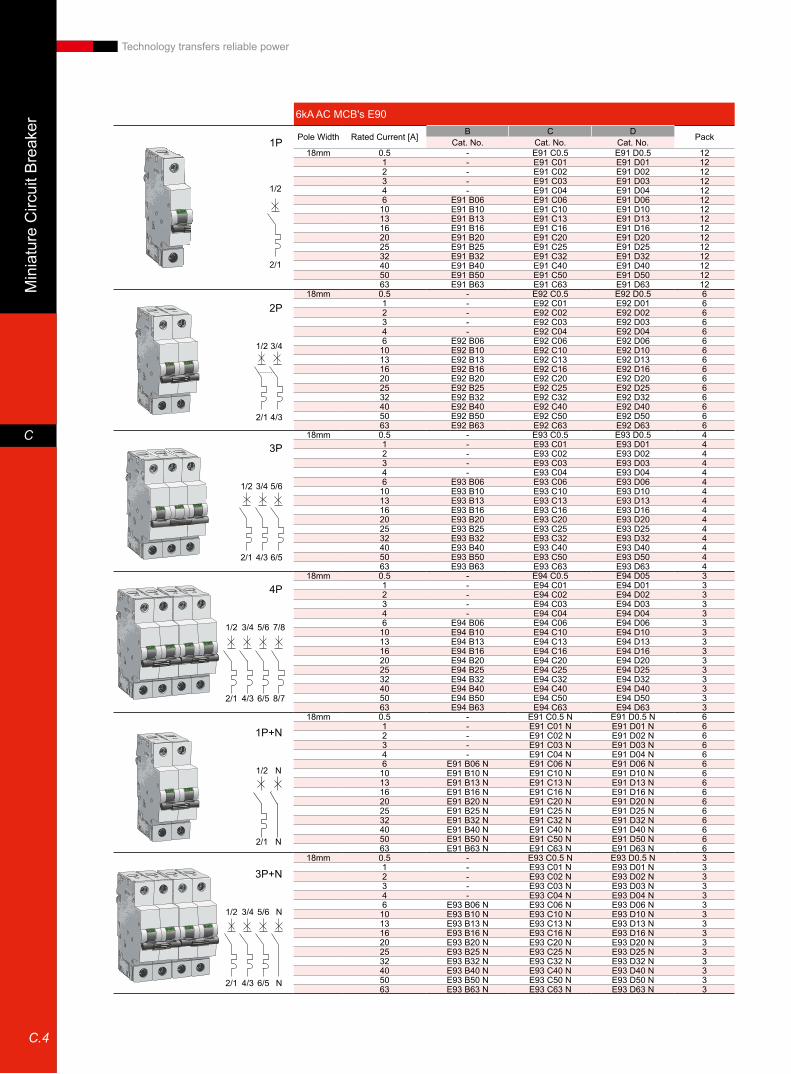
Min
iatu
re C
ircui
t Bre
aker
C
C.4
Technology transfers reliable power
6kA AC MCB's E90
Pole Width Rated Current [A] B C D PackCat. No. Cat. No. Cat. No.18mm 0.5 - E91 C0.5 E91 D0.5 12
1 - E91 C01 E91 D01 122 - E91 C02 E91 D02 123 - E91 C03 E91 D03 124 - E91 C04 E91 D04 126 E91 B06 E91 C06 E91 D06 12
10 E91 B10 E91 C10 E91 D10 1213 E91 B13 E91 C13 E91 D13 1216 E91 B16 E91 C16 E91 D16 1220 E91 B20 E91 C20 E91 D20 1225 E91 B25 E91 C25 E91 D25 1232 E91 B32 E91 C32 E91 D32 1240 E91 B40 E91 C40 E91 D40 1250 E91 B50 E91 C50 E91 D50 1263 E91 B63 E91 C63 E91 D63 12
18mm 0.5 - E92 C0.5 E92 D0.5 61 - E92 C01 E92 D01 62 - E92 C02 E92 D02 63 - E92 C03 E92 D03 64 - E92 C04 E92 D04 66 E92 B06 E92 C06 E92 D06 6
10 E92 B10 E92 C10 E92 D10 613 E92 B13 E92 C13 E92 D13 616 E92 B16 E92 C16 E92 D16 620 E92 B20 E92 C20 E92 D20 625 E92 B25 E92 C25 E92 D25 632 E92 B32 E92 C32 E92 D32 640 E92 B40 E92 C40 E92 D40 650 E92 B50 E92 C50 E92 D50 663 E92 B63 E92 C63 E92 D63 6
18mm 0.5 - E93 C0.5 E93 D0.5 41 - E93 C01 E93 D01 42 - E93 C02 E93 D02 43 - E93 C03 E93 D03 44 - E93 C04 E93 D04 46 E93 B06 E93 C06 E93 D06 4
10 E93 B10 E93 C10 E93 D10 413 E93 B13 E93 C13 E93 D13 416 E93 B16 E93 C16 E93 D16 420 E93 B20 E93 C20 E93 D20 425 E93 B25 E93 C25 E93 D25 432 E93 B32 E93 C32 E93 D32 440 E93 B40 E93 C40 E93 D40 450 E93 B50 E93 C50 E93 D50 463 E93 B63 E93 C63 E93 D63 4
18mm 0.5 - E94 C0.5 E94 D05 31 - E94 C01 E94 D01 32 - E94 C02 E94 D02 33 - E94 C03 E94 D03 34 - E94 C04 E94 D04 36 E94 B06 E94 C06 E94 D06 3
10 E94 B10 E94 C10 E94 D10 313 E94 B13 E94 C13 E94 D13 316 E94 B16 E94 C16 E94 D16 320 E94 B20 E94 C20 E94 D20 325 E94 B25 E94 C25 E94 D25 332 E94 B32 E94 C32 E94 D32 340 E94 B40 E94 C40 E94 D40 350 E94 B50 E94 C50 E94 D50 363 E94 B63 E94 C63 E94 D63 3
18mm 0.5 - E91 C0.5 N E91 D0.5 N 61 - E91 C01 N E91 D01 N 62 - E91 C02 N E91 D02 N 63 - E91 C03 N E91 D03 N 64 - E91 C04 N E91 D04 N 66 E91 B06 N E91 C06 N E91 D06 N 6
10 E91 B10 N E91 C10 N E91 D10 N 613 E91 B13 N E91 C13 N E91 D13 N 616 E91 B16 N E91 C16 N E91 D16 N 620 E91 B20 N E91 C20 N E91 D20 N 625 E91 B25 N E91 C25 N E91 D25 N 632 E91 B32 N E91 C32 N E91 D32 N 640 E91 B40 N E91 C40 N E91 D40 N 650 E91 B50 N E91 C50 N E91 D50 N 663 E91 B63 N E91 C63 N E91 D63 N 6
18mm 0.5 - E93 C0.5 N E93 D0.5 N 31 - E93 C01 N E93 D01 N 32 - E93 C02 N E93 D02 N 33 - E93 C03 N E93 D03 N 34 - E93 C04 N E93 D04 N 36 E93 B06 N E93 C06 N E93 D06 N 3
10 E93 B10 N E93 C10 N E93 D10 N 313 E93 B13 N E93 C13 N E93 D13 N 316 E93 B16 N E93 C16 N E93 D16 N 320 E93 B20 N E93 C20 N E93 D20 N 325 E93 B25 N E93 C25 N E93 D25 N 332 E93 B32 N E93 C32 N E93 D32 N 340 E93 B40 N E93 C40 N E93 D40 N 350 E93 B50 N E93 C50 N E93 D50 N 363 E93 B63 N E93 C63 N E93 D63 N 3
1P
2P
1/2
1/2 3/4
2/1
2/1
1P+N
1/2 N
N2/1
4/3
3P
3/41/2 5/6
4/32/1 6/5
4P
3/41/2 5/6 7/8
4/32/1 6/5 8/7
3P+N
3/41/2 5/6 N
4/32/1 6/5 N

Miniature C
ircuit Breaker
C
C.5
Technology transfers reliable power
E90-B trip current limit curve •
E90-C trip nominal current curve •
E90-D trip nominal current curve •
Ip's nominal current when operating voltage is 230/400V
Estimated short-circuit current Icc (kA)
Ip's nominal current when operating voltage is 230/400V
Ip's nominal current when operating voltage is 230/400V
Estimated short-circuit current Icc (kA)
Estimated short-circuit current Icc (kA)
Ip(k
A)
Ip(k
A)
Ip(k
A)
D63D50D40D32D25D20D16D10D6
D4
D2
C63C50C40C32C25C20C16C10C6
C4
C2
B63B50B40B32B25B20B16B10B6
7
6
5
4
3
2
1
0
7
6
5
4
3
2
1
0
7
6
5
4
3
2
1
0
0.5 1.5 4.5 7.5 103 6
0.5 1.5 4.5 7.5 103 6
0.5 1.5 4.5 7.5 103 6
Curve

AEG Low Voltage Business (China)www.aeg-powercontrol.com
Hotline:400 820 5234
The manual is subject to change without further notice.Paper of this manual is recyclable
Print code::109022009-8
Technology transfers reliable power