aen-152: building a hoop barn - university of kentucky
TRANSCRIPT

Cooperative Extension Service | Agriculture and Natural Resources | Family and Consumer Sciences | 4-H Youth Development | Community and Economic Development
University of KentuckyCollege of Agriculture,Food and EnvironmentCooperative Extension Service
AEN-152
Building a Hoop BarnMorgan Hayes and Josh Jackson, Biosystems and Agricultural Engineering
Preserving hay in a cost-effective man-ner is vital to forage and livestock op-
erations. Three primary options for stored forage exist: haylage, dry hay, or a combi-nation. The dry hay option is dependent upon the availability of equipment, labor, and drying days. Assuming there is an ample drying window, most producers prefer to make dry hay. However, dry hay is at significant risk for deterioration when stored outside (Round Bale Hay Storage in Kentucky, AGR-171). Hoop barns are a cost-effective alterna-tive to pole barns. For example, a farmer might choose a hoop barn when decid-ing to expand hay sales, or for providing cover for costly equipment. Hoop barns have the additional benefit of being a construction project that can be done by the farmer (and a group of friends), which can provide an additional cost savings. This publication follows the construc-tion of two hoop barns built by a local farmer. In this case, hoop barns were built to increase the farm’s hay storage capacity. There are four major steps to building a hoop barn.• Selecting and preparing the site• Setting posts and constructing the
knee wall• Installing the ribs and pulling the tarp• Preparing the final site
Selecting and Preparing the Site When considering where to place a hoop barn, it is important to choose a site that works well with the other struc-tures currently on the farmstead. The site should be accessible without getting in the way of other buildings or utilities. Also note where driveways currently run, where power or water can be accessed easily, and how the ground slopes. When considering hoop barn installation, focus on creating a level spot with decent drain-age that is readily accessible from existing driveways. Also consider the proxim-ity to existing hay storage structures (if increasing hay storage capacity) or any other structures. Proximity to the feeding location is also important.
Site selection criteria• Utilities (water, electric)• Proximity to other structures• Ease of access• Drainage
Once the site is selected, orient the structure so that prevailing weather comes toward the side of the hoop struc-ture. With this orientation, end panels may not have to be used, reducing cost and maintenance. However, the decision to use end panels or not must be based on barn orientation and willingness to receive weather on end bales. Kentucky Wind Directions and Magnitudes: A Tool for Siting Barns (AEN-139) shows the predominant wind direction is from the southwest typically. Another consideration is proximity to any nearby barns (within 75 feet). If hay were to catch fire, close proximity of the barns would increase the likelihood of the fire spreading. When barns are placed close together, a fire in one struc-ture will likely take out the second, so be extra diligent to minimize the chance of spontaneous combustion in wet hay or fire from other causes. The ground for the installation site should be leveled. An excavator can be hired to do this work, as many farmers won’t have the machinery to do it easily. In
Figure 1 a new barn is being constructed next to an existing barn, and the hillside has been cut into, creating two tiers with each tier leveled. The leveled area on the hillside was expanded so it was large enough to accommodate two future hoop barns. Although the farmer does not have a current need for additional hoop barns, having the space ready will make future expansion easier. After the surface has been levelled, the next step is to set corners for the new barn(s). In this example, the first of the two barns was fairly straightforward. It was parallel to the existing barn with openings the same distance from the fence line. The second new barn was par-allel to the other barns, but the opening was shifted forward four feet. Figures 2a and 2b show the string line set up for the higher barn. The line was pulled tight six inches outside of the stakes (where the corners were to be placed) in order to ensure when corner posts were set that they would not press against the string line but the string line would still be a useful guide. The line was pulled to a point much higher on the hill, so it did not touch the ground at any point. The two corners were set closer to the fence first, as that end of the leveled area had been built up more, and this would ensure that the barn was on level ground.
Figure 1. Hoop barns require a level spot with decent drainage.

2
Figure 2. String lines for the hoop barn.
Measurements need to be taken in or-der to complete the final two corners. Use two long tape measures to determine the corner locations. If the barn is square, the two diagonal distances between opposite corners should be equal; the length of the diagonal squared should be equal to the length squared plus the width squared. With a length of 72 feet and a width of 30 feet, the calculation for the diagonal would be:Diagonal Distance = √(302 + 722) = 78 feet
Figures 3a and 3b show how to use the long tape measures to place the final corner. Use two tape measures, one along the length and the second along the di-agonal from the two previously placed corner stakes. When both tapes are pulled taut, the placement for the third corner is identified. Repeat this procedure to find the fourth corner. If desired, use a third tape measure to verify the width on the fourth corner. While it’s not necessary, it is encouraging to confirm that the dimen-sions are correct.
Figure 3. Identifying the hoop barn’s third and fourth corners and representation of the dimensions that would be measured with the tape measures when identifying locations for corner posts.
Setting Posts and Constructing the Knee Wall The hoop barn site has been leveled and the corners marked. Now, it is time to set the four corner posts and mark and set the posts along each side wall. The corner posts and sidewall posts are set in the same manner. In this example, the barns are 72 feet long and 30 feet wide. The posts were set every 6 feet, which meant 13 posts would be set along each sidewall. Mark approximate locations and then dig each hole (Figures 4a and 4b). In this instance, each hole was dug with a 14-inch PTO-driven auger. The holes were approximately 4 feet deep.Treated posts 6 x 6 inches and 10 feet long were placed in each hole (Figure 4c). After the holes are dug, pull a string line down the side wall using the corner posts to pull against, placing it 18 to 24 inches above the ground. The string line ensures the posts are in a straight line along the sidewall. A second line between 4 and 5 feet above the ground can be run using a tape measure. The tape measure acts as a guide, like the string line, to ensure the posts are in line with where the ribs need to be placed, and vertically square to the ground. When describing barn dimensions, the exterior length and width are typi-cally listed. This is true with hoop barns as well. A 72-foot-long by 32-foot-wide hoop barn is 72 feet from the outside of the one post to the outside of the other end post along a sidewall. Similarly, the width is 32 feet from the outside of posts on both sidewalls. If the posts are 6 x 6 (as in this publication), the posts have an actual width of 5.25 inches. To make this barn 72 feet long, the centers of the two outside posts need to be 71 feet 6.75 inches apart. At the same time, all the ribs in this barn were designed to be placed every 6 feet. It is important to note how mounting brackets that will support the ribs and tarp are installed; the mounting brackets for the corners are attached to the outside of the post, and the mounting brackets for the other post mount above the center
3
1 2
78
30
72
a
a
b
b

3
Figure 4. Mark locations for the posts along the sidewall. Dig the holes with an auger. Place the posts in the holes.
of the other sidewall posts. This means the distance is 6 feet from the outside of the corner post to the center of the first interior post on the sidewall. The distance will then be 6 feet from center to center for all interior posts. If the barn purchased uses different mounting methods or spac-ing, you will need to measure the length accordingly. As shown in Figure 5a, the post is in the hole on the left. In Figure 5b, the posts have been set at 6 foot on center and a level has been used on two sides to ensure that the post is vertical. Once the post is in the correct position, one person holds the
post while the second pours two prepared 80-pound bags of concrete into the hole. While the concrete is wet, final adjust-ments can be made to ensure the post is square to the string line that represents the sidewall and correctly spaced (Figure 5c). Some people choose to pour concrete to the top of the hole, however there are issues with doing that. When using con-crete to anchor posts, it is best to keep the concrete below the frost line. This keeps the concrete from heaving during freeze-thaw events, which keeps the barn square longer. In this example, two 80-pound
bags of concrete gave us 18 to 24 inches of dirt above the concrete, leaving the concrete below the typical frost line. As the concrete starts to harden, soil is put back on top of the concrete. About 8 to 12 inches of soil was placed in the hole at a time, and the soil was tamped down using a digging iron (Figure 6a). Figure 6b shows tamped holes with dirt mounded around each post. Although tamping reduces the settling around the post, mounding the dirt will still help keep enough dirt close to the post as settling occurs. It also provides extra stability and diverts water away from the posts.
Figure 5. Anchor the posts with prepared concrete. Ensure that the posts are upright and properly spaced. Backfill the post hole with soil.
a
a
b
b
c
c

4
Figure 7. The string line provides a way to visualize the height of the knee wall.
Figure 6. Tamp the soil down with a digging iron. Mound the dirt around the post for extra stability and to divert water away from the post.
Once all the posts are set, the next step is to determine the height of the side wall or knee wall. A string line is useful to visualize the height. First, look at the posts to see which ones appear shortest. Pull a line between the first two corner posts along the side that appeared to have the shortest posts, leaving a couple inches above the string line on the shortest post. Use a hanging level on the string line to ensure the line is level (Figure 7a). Once the first side is level, wrap the string line around the second corner post a few times and continue pulling the string to the third corner. Wrapping the string around the corner a few times keeps it from moving when the line is ad-justed on the next length or width. Again, use the hanging level to ensure the string line is level and secure the third corner post by wrapping the string around the post. Repeat the procedure from the third to fourth corner post and from the fourth back to the first corner post. If all the lines were leveled prop-erly and there was no difference in height turning the corners, the pulled string line from the fourth to the first corner should be level with no adjustments. If the string line is above any of the posts, all of the string line sections should be adjusted down and re-leveled. In this example, the farmer incorrectly guessed the shortest post and had to repeat the process. Once the string line is complete, use a tape measure to measure 5.5 inches down from the line and a speed square to mark the outside of each post at that distance below the string line (Figures 8a and 8b). Once all posts are marked, the string line can be removed.
Figure 8. Measure down from the string line. Mark the bottom line using a speed square.
a
a b
b

5
Figure 9. Treated 2 x 6 12-feet-long fence boards are placed above the marked line on the post and screwed into each post. The fence posts are cut off at the top of the 2 x 6.
Place treated 2 x 6 inch 12-feet-long fence boards above the marked line on the post and screw them into each post (Figure 9a). The top of each 2 x 6 should now be in line with where the string line was previously pulled and leveled. This means that if the 2 x 6 is used as a guide and the posts are cut off above the 2 x 6, there will be a level base on which to place the ribs for the hoop structure (Figure 9b). Before constructing the ribs, a few more pieces of treated lumber need to be added to the knee wall. Another series of treated 2 x 6 boards were placed on top of the knee wall flush with the outside of the 2 x 6 boards previously attached (Figure 10a). The metal ribs of the hoop will be attached to this 2 x 6.
Figure 10. Treated 2 x 6 inch 12-feet-long fence boards are placed on the top of the knee wall and 36 inches up in the inside of the sidewall and screwed into each post. One run of metal siding was placed along each sidewall.
Other 2 x 6 boards were also placed on the inside of the posts 36 inches below the top along the length (Figure 10b). These interior 2 x 6 boards provide some additional support, often securing hay that would otherwise try to escape. One piece of metal siding was run down the sides outside of the posts (Figure 10c). The metal siding is not necessary, but hay is sold from these barns. Siding reduces rain blowing in and, more importantly, reduces sun hitting the bales. While sun bleaching is not of major concern for your own animals’ hay consumption, it does make selling hay more difficult. It is impor-tant to note that you will want at least 18 to 24 inches uncovered height along the sidewalls to encourage air movement.
a
a
b
b c
6
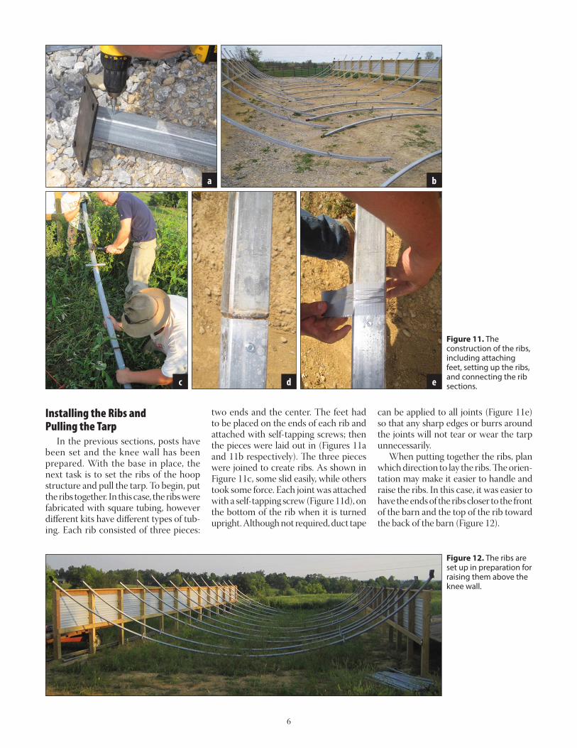
Installing the Ribs and Pulling the Tarp In the previous sections, posts have been set and the knee wall has been prepared. With the base in place, the next task is to set the ribs of the hoop structure and pull the tarp. To begin, put the ribs together. In this case, the ribs were fabricated with square tubing, however different kits have different types of tub-ing. Each rib consisted of three pieces:
Figure 11. The construction of the ribs, including attaching feet, setting up the ribs, and connecting the rib sections.
two ends and the center. The feet had to be placed on the ends of each rib and attached with self-tapping screws; then the pieces were laid out in (Figures 11a and 11b respectively). The three pieces were joined to create ribs. As shown in Figure 11c, some slid easily, while others took some force. Each joint was attached with a self-tapping screw (Figure 11d), on the bottom of the rib when it is turned upright. Although not required, duct tape
can be applied to all joints (Figure 11e) so that any sharp edges or burrs around the joints will not tear or wear the tarp unnecessarily. When putting together the ribs, plan which direction to lay the ribs. The orien-tation may make it easier to handle and raise the ribs. In this case, it was easier to have the ends of the ribs closer to the front of the barn and the top of the rib toward the back of the barn (Figure 12).
Figure 12. The ribs are set up in preparation for raising them above the knee wall.
a b
c d e

7
Because all the ribs were identical with offsets for attaching cross tubing, the ribs for the front and back of the structure had a few modifications. The attachment points for the cross braces (which secured each rib to the next) needed to be cut off on the side facing outward (Figures 13a, 13b). Again, these cuts were covered with duct tape to reduce wear and tear on the tarp (Figure 13c). Taping is not suggested in manufacturer instructions received with this product, but with the tension
Figure 13. Final modification of the outside ribs.
Figure 14. Lifting the ribs and attaching them to the knee walls.
on the tarp, even a small sharp edge could create a hole that would be very difficult to patch. The next step is to put the ribs upright and secure them. In order to move the ribs upright, someone needs to hold each rib steady at the center while the feet are secured (Figure 14a). A front loader on a tractor can accomplish this task. Other options include scaffolding and boom lifts. In this case, the outside of a 325-gal-lon tank (tote) on a pallet was used to
create a cage to hold materials needed for construction (Figure 14b). Between each rib were three cross braces. One of the cross braces being added is shown in Figure 14c. Don’t rush, and attach feet securely. Attaching cross braces without the feet fully secured will risk letting wind blow over ribs, which can cause damage to the 2 x 6 plating and foot. As shown in Figure 14d, the second rib was knocked over and the 2 x 6 top plate needed re-placement.
a
a
b
b
c
c d

8
In order to prevent this from happen-ing again, lag screws were attached to all feet and sunk into the plate, and post and a rope was used to stabilize the ribs while putting in the cross braces. As each rib went up, a nylon rope was thrown over the top (Figure 15a) and held by a person on the ground (Figure 15b). Pressure against toppling was provided by pulling back on the rib as soon as the first cross brace was in place. While this step took more time and required an extra pair of hands, it did prevent the wind from blow-ing anything loose. Between the outside two ribs on each end were four additional braces in ad-dition to the three cross braces that run along the length of the structure (Figure 16a). For the first barn, half the distance between the three main cross braces was approximated. However, when these braces were not perfectly centered, it was difficult to attach them with the self-tapping screws. In order to get the braces perpendicular to the ribs, the two ribs closest to each end were measured and marked for all the braces’ attachment points (Figure 16b). While this measure-ment may seem overly precise, it did make installation quicker and easier. Once all the ribs were up and all braces were in place, finish preparing the tarp for installation. Ratchets were placed on the outside of each post, so that tension could be maintained across the tarp from both sides after it was pulled into position (Figures 17a, 17b, and 17c).
Figure 15. Using rope to stabilize ribs while the ribs are being mounted to the knee wall.
Figure 16. Adding additional cross bracing between the outside two ribs and marking these locations on the ribs.
Figure 17. Drilling pilot hole through metal siding, attaching ratchet with lag screw, and view of ratchets along sidewall, with one ratchet per post.
a
a
a
b
b
b c

9
Figure 18. Feeding poles through the tarp along the sidewall and attaching pole pieces with self-taping screws.
Figure 19. Setting up the nylon ropes to pull the tarp and pulling it into position.
The process for unwrapping the tarp was included by the manufacturer. On the first hoop barn, instructions for lay-ing out the tarp were followed exactly. Unfortunately, the tarp was upside down. No one noticed this until the tarp had been pulled about halfway across the structure. The tarp then had to be pulled completely across the structure, picked up, and manually moved back to the start-ing side, a very slow and awkward process. There are no pictures of this unfortunate event because it took everyone available plus additional help to move and reset the tarp, before the process of pulling it across the ribs could begin again. Just a reminder: Check that the seams are on the inside prior to pulling the tarp to avoid an aggravating error in procedure. The tarp has a metal pole that runs along the length to strap down the tarp along both sidewalls. In this case, the poles were in three pieces. They needed to be threaded through the tarp (Figure 18a) and, at each connection, attached with a self-tapping screw (Figures 18b, 18c) and duct-taped like the rib connections. In order to pull the tarp, one end of nylon rope was attached to the poles that ran along the sidewall and the other end was thrown over the structure. Five evenly spaced ropes were utlized (Figure 19a). The goal is to pull all five ropes evenly (Figures 19b and 19c). Make sure everyone involved has a good grip on their rope. Be aware of the wind, as a good gust can really pull the tarp (Figure 19d).
a
a
b
b
c d
c

10
The tarp is in position when the poles reach the top plate along each sidewall. As shown in Figures 20a and 20b, sometimes minor adjustments need to be made by pulling on different ropes. Once the tarp is in position, the wind does not seem to move it as readily; however, make sure to get it strapped down before finishing for the day.
Final Site Preparation This final section addresses tying down the tarp and lacing tarp ends as well as final site preparation. The first step in at-taching the tarp to the structure is to use the ratchets along the sidewall (Figure 21a). The tarp has openings where straps can be pulled around the poles that run along the sidewalls, then fed through the ratchet (Figure 21b). Until the tarp is tightened front to back, it is best to catch each strap with a ratchet as loosely as possible (Figure 21c). After the ends are laced, finish tightening the ratchets on the sidewalls. Some of the older hoop designs use lacing along the sidewalls. An addi-tional board must be run approximately 30 inches below the top board for lacing to be used (Figure 22). Lacing the sidewall takes a lot of time and this ratchet design was quite a bit faster. However, both methods of attachment should secure the tarp well.
Figure 20. Leveling out the tarp along each sidewall to ensure ratchets will work.
Figure 21. Ratchets to hold the tarp along the sidewall.
Figure 22. Lacing to hold the tarp along the sidewall.
a
a
b
b c

11
In order to put tension on the tarp front to back, there is a strap for lacing both ends of the barn. This tarp design has an eyelet about every 18 inches. The strap runs through an eyelet then around the outside rib and back to the next eyelet. In the back end of the first barn that was
Figure 23. Beginning to lace the tarp along the end starting from the center at the top of the hoop.
Figure 24. Finalizing the lacing on the end and attaching a small ratchet to cinch in the end of the tarp.
laced, work started from one side and worked to the other. It was very difficult to maintain tension across the whole width of the structure. When working on the second end, the farmer chose to work from the middle, which was much easier. As shown in Figures 23a, 23b, and 23c,
create a loop in the center of the strap and pull the loop through the center eyelet, then feed both ends of the strap through the loop and pull tight. All the tension is pulled from the center as the strap is laced down to the side of the structure (Figure 23d). Once the tarp is tight front to back, tie off the ends of the strap that were used to lace the tarp. Lace through the final eyelet twice and tie back to the rib and then trim the excess strap (Figure 24a). With the tarp pulled tight, there may be overhang on the tarp. This tarp has another strap attached to the front and back posts with smaller ratchets to pull down these small endcaps (Figure 24b). Instead of lacing some of the newer tarps use individual ratchet straps going from the end rib to the eyelet (Figure 25). Similar to the ratchets on the sidewall, these ratchets will make set up quicker and tension easier to maintain.
a
a
b
b
c d

12
Figure 25. Tarp tightened using ratchets rather than lacing for the end.
The last thing that was done before hay was stored in the barn was to add gravel. Gravel creates a base on which to drive. Within the barn, the ground was already leveled. Fabric filter was put down, and then covered with an eight-inch-thick layer of gravel. Fabric filter is not an
Figure 26. Preparing to spread gravel in the barn over filter fabric.
inexpensive product, but it significantly reduces the amount of gravel needed to finish the floor of the barn. Because trac-tors and heavier trucks will be driven in this area, a solid, stable floor is essential. If filter fabric is not used, mud and dirt will move into the air spaces between the small rocks, and as a result, the floor won’t drain. This may result in heaving during freeze-thaw cycles. Filter fabric allows for a cost savings as less additional rock is required in order to get drainage (so the bottom of the hay bales don’t rot due to wet ground). Choose a good location to have gravel dumped, which will make the process much easier. The rock pile should be close but not in the way of spreading the rock. In Figure 26a the pile was dumped between two barns where it was easily accessible but it did not impede driving in and out of the barn. There are no pictures of fabric filter because it had to be quickly covered so the wind wouldn’t move it, but you can see it peeking out in Figure 26b. One of the hoop barns has a noticeable slope at the back of the barns. Because this gradient is quite steep from the leveling process and there is a high tensile fence
behind the barn, the farmer decided to rock the slope with large rock (Figure 27). This rocked slope prevents weeds growing up into the fence line and ensures this area does not need to be mowed. This rocked hillside should also prevent the base on the back of the barn from eroding.
Figure 27. Larger rocks to prevent erosion and vegetative growth along the slope behind a hoop barn.
a b

13
An additional step that could be beneficial for farmers is to add drainage around their barns. In this example, a mini-excavator was used for a weekend to dig ditches along both sides of the hoop barns as well as along the front. It is important to note that all the ditches were lined with fabric filter and filled in with large rock. Figure 28a and 28b show the excavation process, and Figure 28c shows the fabric filter around the large
Figure 28. Creating drainage along the sides of the hoop barns. Ditches include large rock surrounded by filter fabric and covered with smaller rock.
rock under the entrance to the barn. Note that the large rock has more space to move water, but without fabric filter this drain would quickly clog. The drains are about 24 inches deep, a necessary depth since these barns are along a fairly long hillside, which can create some runoff concerns. Figure 28d shows a drain after one year. It’s working well and the barn has remained dry inside.
The 30 feet wide by 72 feet long hoop barns documented in this publication should be able to store approximately 144 5 feet x 6 feet bales or 266 4 feet x 5 feet bales (depending upon how the bales are stacked). While building a hoop barn is somewhat complicated, at least the first time, it is an achievable project to carry out with a group of farmers, friends, and family. Careful planning, as outlined in this document, will ensure that the hoop barn constructed will provide many years of hay storage and savings.
a b
c d

Educational programs of Kentucky Cooperative Extension serve all people regardless of economic or social status and will not discriminate on the basis of race, color, ethnic origin, national origin, creed, religion, political belief, sex, sexual orientation, gender identity, gender expression, pregnancy, marital status, genetic information, age, veteran status, or physical or mental disability. Issued in furtherance of Cooperative Extension work, Acts of May 8 and June 30, 1914, in cooperation with the U.S. Department of Agriculture, Nancy M. Cox, Director, Land Grant Programs, University of Kentucky College of Agriculture, Food and Environment, Lexington, and Kentucky State University, Frankfort. Copyright ©2020 for materials developed by University of Kentucky Cooperative Extension. This publication may be reproduced in portions or its entirety for educational or nonprofit purposes only. Permitted users shall give credit to the author(s) and include this copyright notice. Publications are also available on the World Wide Web at www.ca.uky.edu.Issued 7-2020
ReferencesCollins, M., Ditsch, D., Henning, J.C.,
Turner, L.W., Isaacs, S., and Lacefield, G.D. 1997. Round Bale Hay Storage in Kentucky (AGR-171). University of Kentucky Cooperative Extension Ser-vice. Available at: http://www2.ca.uky.edu/agcomm/pubs/agr/agr171/agr171.pdf.
Jackson, J., Hayes, M., and Dixon, M. 2019. Kentucky Wind Directions and Magnitudes: A Tool for Siting Barns (AEN-139). University of Ken-tucky Cooperative Extension Service. Available at: http://www2.ca.uky.edu/agcomm/pubs/AEN/AEN139/AEN139.pdf.