aep eastern system pre-1930s era lattice tower and
TRANSCRIPT

AEP Eastern SystemPre-1930s Era Lattice Tower and
Transmission Line SystemSRRTEP-Western Committee

Agenda
• Discussion of AEP’s Asset Management Strategy
• Introduction to AEP’s Pre-1930s Era Lattice Tower and Transmission Line System in eastern footprint • Description of the System• Condition of the System
• Considerations of Rehabilitate and Replacement
2

AEP’s Asset Management Strategy
What’s Causing Issues Now?
•Outage Rates by Voltage Class•T-SAIDI, T-SAIFI-S, T-SAIFI, T-MAIFI
•Outage Impacts•SAIDI, SAIFI, CMI, CI•Contributions from each asset
Historical Performance
What Could Cause Outages in the Future?
•Engineering Assessments•Field Assessments
•Reported Conditions•Spare Part Availability
•Operational Issues•Contributions from each asset
Asset Conditions
What’s Driving Future Risk?
•Customer Load at Risk•Number of Customers at Risk
•AEP-D, AEP-Indus, AEP-Wholesale•(Behind Meter CS Estimations)
•Radial Facilities•Restoration Ability•System Risk•Contributions from each asset
Future Risk
3

AEP Needs Assessment for Transmission Lines
• AEP conducts a Serviceability Assessment of an asset class such as Oil Circuit Breakers, Air Blast Breakers, steel tower lines constructed prior to 1930s • AEP defines “serviceability” as the evaluation of the asset type using current standards
and guidelines• Does it meet current design criteria? • Can it deliver expected reliability? • What is the risk to the public?
• History of failures of individual components help determine the status of each component on the “bathtub failure curve”
• The serviceability assessment for the asset class guides replacement or rehabilitation decisions
4

Key Considerations of Serviceability AssessmentTransmission Lines
• The original designs do not account for modern wind and ice loading requirements
• The conductors have deteriorated
• The configuration provides inadequate lightning protection
• Demonstrable wear on most conductor attachment hardware
• Significant loss of strength due to corrosion on hardware and insulators
• Structures have above and below grade loss of galvanizing
• Most towers are not readily accessible adding cost and time to restoration
5

AEP System in 1930
138 kV transmission lines
6

7Backfilling crew on tower construction, 1925
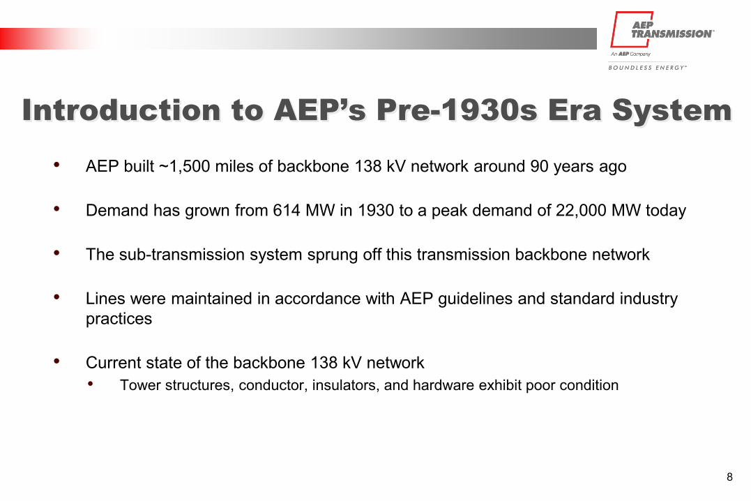
Introduction to AEP’s Pre-1930s Era System • AEP built ~1,500 miles of backbone 138 kV network around 90 years ago
• Demand has grown from 614 MW in 1930 to a peak demand of 22,000 MW today
• The sub-transmission system sprung off this transmission backbone network
• Lines were maintained in accordance with AEP guidelines and standard industry practices
• Current state of the backbone 138 kV network• Tower structures, conductor, insulators, and hardware exhibit poor condition
8
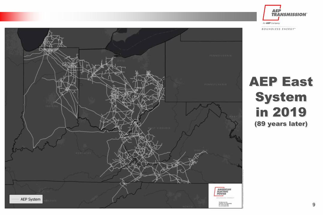
AEP East System in 2019(89 years later)
9

Condition & Impacts of the DegradedPre-1930s Era System
• These transmission line assets are clearly in the accelerated deterioration phase of their life
• Significant deterioration results in loss of strength and performance posing a significant risk of failure under conditions the assets should be able to withstand• May cause frequent and extended outages• May create significant economic losses• May endanger public safety
10

11
Conditions of System
Ground line Corrosion
• The system is evaluated holistically, including an assessment of insulators, conductors, ground line corrosion and tower members
• The next 9 slides include photos of lattice tower components that represent the condition prevalent across AEP’s pre-1930s era lattice transmission line network
Tower Members
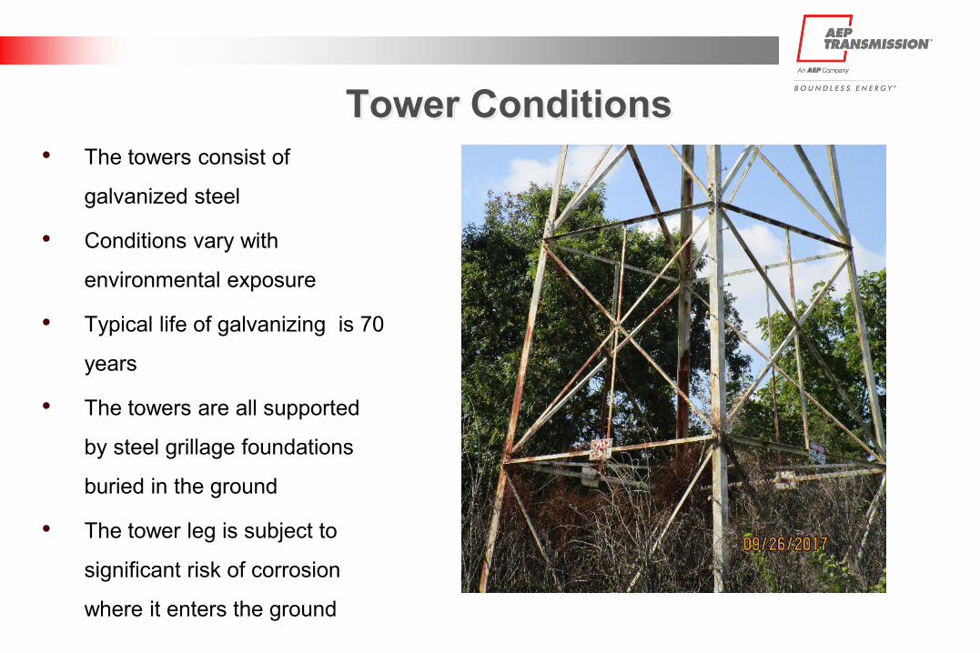
Tower Conditions• The towers consist of
galvanized steel
• Conditions vary with
environmental exposure
• Typical life of galvanizing is 70
years
• The towers are all supported
by steel grillage foundations
buried in the ground
• The tower leg is subject to
significant risk of corrosion
where it enters the ground

Ground Line Corrosion
• Tower legs have lost greater than 50% of section due to corrosion
• Subject to collapse
Insulator & Hardware Corrosion
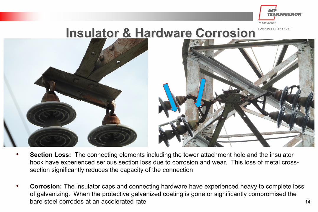
• Section Loss: The connecting elements including the tower attachment hole and the insulator hook have experienced serious section loss due to corrosion and wear. This loss of metal cross-section significantly reduces the capacity of the connection
• Corrosion: The insulator caps and connecting hardware have experienced heavy to complete loss of galvanizing. When the protective galvanized coating is gone or significantly compromised the bare steel corrodes at an accelerated rate 14

Broken Insulators
• Broken, cracked and otherwise damaged insulators lead to premature flashover causing permanent outages
• When the insulator assembly breaks, the wire falls to the ground potentially damaging other conductors, and present an increased public safety concern
15

Typical 1930s Lattice Line
• Pitting and deterioration of base steel
• Corroded connecting pins will drop conductor when they fail
16

Typical 1930s Lattice Line
• Insulator failure due to corrosion and wear of connecting element
• Close up views of connections showing corrosion and loss of section
17
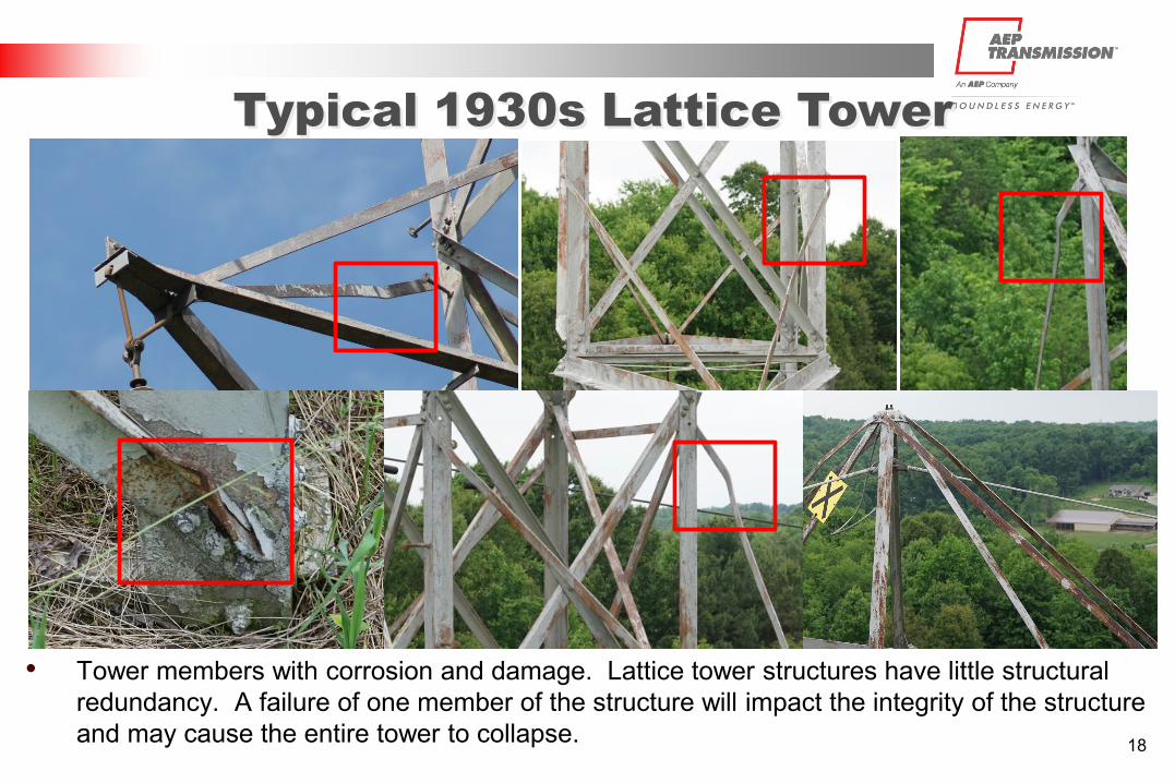
Typical 1930s Lattice Tower
• Tower members with corrosion and damage. Lattice tower structures have little structural redundancy. A failure of one member of the structure will impact the integrity of the structure and may cause the entire tower to collapse. 18

• Significant deterioration exists
• Aluminum Conductor Steel Reinforced (ACSR) conductor consists of aluminum strands wrapped around a core of galvanized steel strands. The steel provides the structural strength. Like other steel elements the strands of the core have also lost the galvanized coating and steel section
• The degraded state results in significant loss of tensile strength and potential risk to the public if the conductor was to fail and fall to the ground
Typical 1930s Era Steel Core Conductor
19

• Conductor damage is usually not visible in a field inspection
• Specific conductor samples, from the belly of the sag (lowest point) and/or inside the clamps at the insulators, have confirmed significant corrosion
• During the restoration or construction activities, conductors often break at adjacent locations due to handling, introducing a potential safety risk and increase public safety concern
Typical 1930s Era Steel Core Conductor
20
Strands Broken at clamp
Broken Shield Wire

Estimated Asset Expected Life• Timeframe guided by typical industry experience
• AEP focuses on evaluating the condition and performance of each asset and the risk that the failure of each poses to the system, connected customers, personnel and the public
Asset Type CEATI Estimated Expected Life of Transmission Line Components
(Years)*
Wood Poles 35-75
Wood Cross Arms 20-55
Steel Towers 35-100
Steel Poles 50-80
Conductor 40-80
Porcelain Insulators 40-50
Polymeric Insulators 10-30
*The Centre for Energy Advancement through Technological Innovation (CEATI) Report No. T144700-3257: Statistical Data and Methodology for Estimating the Expected Life of Transmission Line Components
21

Effect of Age on Component Failure
• All material behaves similarly in that failures increase dramatically at the end of life. This is known as the “bathtub curve”
• The timelines and rates vary by components and material. (e.g. wood cross-arms fail sooner than wood poles; polymer insulators fail sooner than porcelain)
• All assets are made up of individual components• Each component has a failure profile unique to its material
22

Asset Rehab or Replace Decision• The performance
characteristics of an asset degrade with time due to deterioration of the individual component failures
• Improvements are gained through rehabilitation efforts
• At some stage maintenance and rehabilitation is no longer a cost effective method to restore reliability
• If the replacement decision is delayed too long the risk to reliability and the public becomes unacceptable
Rehabilitate Replace
As designed Performance
23
Rehabilitation Event #1
Rehabilitation Event #2
Path without Rehab
Path with Rehab

Rehabilitate vs. ReplaceCharacteristics of Rehabilitation projects
• Individual material components entering the early life failure stage
• Conditions where limited investment can substantially improve reliability
• Rehabilitation options are component specific
Characteristic of Replacement projects
• Assets well into lifespan with experienced and/or expected multiple component failures that impact future performance – reliability, resilience, safety
• Assets that require significant replacements where the investment is not commensurate with the expected improved performance or life extension
• Asset that have inadequate or obsolete design characteristics
• Lack of vendor support and/or replacement parts
24

Summary• This presentation is for educational purposes regarding a group of AEP
assets and is intended to provide useful background information for customers and stakeholders to support future discussions
• While this presentation is intended to provide a useful reference for future SRRTEP discussions, it is not intended to define any specific project or asset need
• All individual asset and project-specific needs, including those that include any Pre-1930s era lattice towers, are presented under the PJM planning process beginning with identified asset-specific needs
25