aerobic and anaerobic operation of an active membraneless direct methanol fuel cell
TRANSCRIPT

Electrochemistry Communications 17 (2012) 22–25
Contents lists available at SciVerse ScienceDirect
Electrochemistry Communications
j ourna l homepage: www.e lsev ie r .com/ locate /e lecom
Aerobic and anaerobic operation of an active membraneless direct methanol fuel cell
Alfred Lam a,b, Mohammad S. Dara a, David P. Wilkinson a,b,⁎, Khalid Fatih a,b
a Department of Chemical & Biological Engineering and Clean Energy Research Centre, University of British Columbia, 2360 East Mall, Vancouver, BC, Canada V6T 1Z3b National Research Council, Institute for Fuel Cell Innovation, 4250 Wesbrook, Vancouver, BC, Canada V6T 1W5
⁎ Corresponding author at: Department of Chemical & BEnergy Research Centre, University of British Columbia,Canada V6T 1Z3. Tel.: +1 604 822 4888; fax: +1 604 82
E-mail address: [email protected] (D.P. Wilki
1388-2481/$ – see front matter © 2012 Elsevier B.V. Alldoi:10.1016/j.elecom.2011.12.020
a b s t r a c t
a r t i c l e i n f oArticle history:Received 22 November 2011Received in revised form 28 December 2011Accepted 30 December 2011Available online 9 January 2012
Keywords:MembranelessDirect methanol fuel cellDirect methanol redox fuel cellAerobicAnaerobic
In this paper the operational and architectural flexibilities of a membraneless direct liquid fuel cell weredemonstrated under aerobic and anaerobic configurations at 60 °C and 1 atm. The aerobic membranelessdirect methanol fuel cell (DMFC) was fed an anolyte solution of 1 M CH3OH/0.5 M H2SO4 and an air oxidant.The anaerobic membraneless direct methanol redox fuel cell (DMRFC) was fed an anolyte solution of 1 MCH3OH/0.1 M HClO4 and a catholyte solution of 2 M Fe(ClO4)3 and 0.22 M Fe(ClO4)2 oxidant. For bothcases the membraneless architecture performed significantly better than for the conventional PEM archi-tecture with Nafion® 117. The maximum power density for the membraneless and Nafion® 117 basedDMFC was 52 mW⋅cm−2 and 41 mW⋅cm−2 respectively. The maximum power density for the membrane-less and Nafion® 117 based DMRFC was 46 mW⋅cm−2 and 34 mW⋅cm−2 respectively. In addition, anaerobicoperation using a Fe2+/Fe3+ catholyte gave similar performance to that for air as an oxidant. Both mem-braneless and anaerobic operation can result in significant cost reduction with improved operationalflexibility.
© 2012 Elsevier B.V. All rights reserved.
1. Introduction
A directmethanol fuel cell (DMFC) offers the advantage of extendedand continuous operation through the replacement of a fuel cartridge. Aconventional DMFC membrane electrode assembly (MEA) consists of apolymer electrolyte membrane (PEM) compressed between an anodeand cathode. To simplify this design, the removal, replacement or inte-gration of the membrane electrode assembly (MEA) components hasbeen studied by various research groups [1–7].
Previous work by the authors has focused on a novel passive air-breathing membraneless DMFC operating under ambient condi-tions (25 °C, 1 atm) [6,7]. In the novel architecture, the conventionalPEM was eliminated and replaced with an open spacer and a liquidelectrolyte for proton conduction, and a 3D electrode structure to ad-dress fuel crossover. A significant advantage to this design is the opera-tional flexibility. It can be operated under conditions with differentfuels, electrolytes and oxidants. In this preliminary study, PEMbased (Figs. 1a, 2a) and membraneless (Fig. 1b) configurations of aDMFC and direct methanol redox fuel cell (DMRFC) (Fig. 2b) aredemonstrated under active conditions. Both membraneless and
iological Engineering and Clean2360 East Mall, Vancouver, BC,2 6003.nson).
rights reserved.
anaerobic operation can result in significant cost reduction and use ina wider number of applications without sacrificing performance.
The aerobicmembraneless DMFCutilizes a 3D anode structure and afuel electrolyte (1 MCH3OH+0.5 MH2SO4) to extend the reaction zoneandmitigate/eliminate the effects ofmethanol crossover [6]. The protonconduction within the open spacer is provided by a liquid electrolyteand air is used as an oxidant. The half cell reactions and overall reaction(25 °C, 1 atm) for this system are shown in Eqs. (1)–(3) [6].
Anode Reaction : CH3OH lð Þ þH2O lð Þ→CO2 gð Þ þ 6Hþþ 6e− Ea°¼ 0:016 V ð1Þ
Cathode Reaction : 3=2O2 gð Þ þ 6Hþ þ 6e−→3H2O lð Þ Ec° ¼ 1:229 V ð2Þ
Overall Reaction : CH3OH lð Þ þ 3=2O2 gð Þ→2H2O lð Þ þ CO2 gð Þ E°¼ 1:213 V ð3Þ
The anaerobic membraneless DMRFC is a hybrid of a redox flowbattery and a membraneless DMFC. It operates in much the sameway as the previous system, except that the fuel electrolyte and theair oxidant are replaced with a 1 M CH3OH+0.1 M HClO4 and a 2 MFe(ClO4)3+0.22 M Fe(ClO4)2 metal ion redox catholyte respectively.The total iron concentration was kept at 2.22 M (9:1 ratio of theferric to ferrous) to simulate a redox regeneration process withan efficiency of 90% [8]. In addition a 3D cathode structure is imple-mented to extend the reaction zone and mitigate/eliminate theeffect of liquid oxidant crossover. The half cell reactions and overall

MPL Diffusion Barrier
Cathode
-
H+
3D Anode
Nafion® 117
Anode Flow Field Plate
Cathode Flow Field Plate
MPL Diffusion Barrier
Cathode
0.5M H2SO4
e-
H+
3D Anode
Open Spacer
Anode Flow Field Plate
Cathode Flow Field Plate
a)
b)
e
Fig. 1. a) Aerobic PEM based DMFC; b) Aerobic membraneless DMFC.
23A. Lam et al. / Electrochemistry Communications 17 (2012) 22–25
reaction at (25 °C, 1 atm) for this system are shown in Eqs. (4)–(6)[9].
Anode Reaction : CH3OH lð Þ þH2O lð Þ→CO2 gð Þ þ 6Hþ þ 6e− Ea° ¼ 0:016 V ð4Þ
Cathode Reaction : 6Fe3þ þ 6e−→6Fe2þ Ec° ¼ 0:771 V ð5Þ
Overall Reaction : CH3OHþ 6Fe3þ þ H2O lð Þ→CO2 gð Þ þ 6Hþ þ 6Fe2þ E°¼ 0:755 V
ð6Þ
There are several advantages to the anaerobic DMRFC. Since theactivity of the Fe3+ is comparable on Pt and C, precious group metal(PGM) catalysts on the cathode are not required [9]. This significantly
3D Cathode
e- H+
3D Anode
Nafion® 117
Anode Flow Field Plate
Cathode Flow Field Plate
MPL Diffusion Barrier
3D Cathode
1M CH3OH/0.1M HClO4e- H+
3D Anode
Open Spacer
Anode Flow Field Plate
Cathode Flow Field Plate
MPL Diffusion Barrier
a)
b)
Fig. 2. a) Anaerobic PEM based DMRFC; b) anaerobic membraneless DMRFC.
reduces the cost and eliminates fuel crossover since methanol is notactive on carbon. Additionally, the regeneration of the catholytefrom Fe3+ to Fe2+ requires no power and can be done in an in-situpower producing process [10].
2. Material and methods
2.1. Electrode preparation
An ink spray deposition method was used to fabricate the elec-trodes. The 3D anode structure was made by stacking a BASF TGPH-60 carbon fiber paper (CFP) with 20% wet proofing with a catalystloading of 3.0 mg∙cm−2 Pt–Ru black and 5.0 mg mg∙cm−2 Pt–Rublack catalyst+Nafion® loading of 15 wt.% on opposing sides and aSIGRACET 25BC diffusion layer with 5% polytetrafluoroethylene(PTFE) microporous layer (MPL). The cathode of the DMFC wasmade by depositing a loading of 6.1 mg∙cm−2 Pt black catalyst witha Nafion® loading of 10 wt.% and a 1.00 mg∙cm−2 Cabot carbon sublayerwith 20 wt.% PTFE onto a BASF TGPH-60 CFP with 20% wet proofing.
The anode structure for the DMRFC was similar to the DMFC butwithout the SIGRACET 25BC layer. A 3-D cathode was fabricated bystacking a layer of BASF TGPH-120 (no wet proofing), a layer of2.5 mg/cm2 C (Vulcan XC-72) with 10% Nafion loading and a SIGRA-CET 25BC diffusion layer with 5% PTFE MPL.
2.2. Solution preparation
The anolyte was prepared with methanol, sulfuric acid or perchloricacid and 18.2 MΩ deionized (DI) water. The anolyte compositionsconsisted of 1 M CH3OH/0.5 M H2SO4 and 1 M CH3OH/0.1 M HClO4
for the respective aerobic and anaerobic systems. The catholyte forthe DMRFC was prepared with ferric perchlorate and ferrous per-chlorate from GFS Chemicals and 18.2 MΩ deionized (DI) water toa concentration of 2 M Fe(ClO4)3 and 0.22 M Fe(ClO4)2.
2.3. Spacer and membrane preparation
The spacer was cut from a silicone sheet with a thickness of0.410 mm and an open area of 3.24 cm2. Nafion® 117 was preparedby boiling in the following: 3% H2O2, 18.2 MΩ DI water and 0.5 MH2SO4 for 30 min with a DI water rinse between each step.
2.4. Fuel cell configuration and testing
The electrode assembly was incorporated into single cell under acompression pressure of 10 psi and was operated at 60 °C and 1 atm.Two serpentine graphite plates with channel dimensions of 1 mm
0
0.1
0.2
0.3
0.4
0.5
0.6
0.7
0.8
0.9
1
0 25 50 75 100 125 150 175 200 225 250
Current Density (mA·cm·cm-2)
Cel
l Vo
ltag
e (V
)
0
10
20
30
40
50
60P
ow
er D
ensi
ty (
mW
·cm
·cm
-2)
Membraneless DMFCNafion 117 DMFCMembraneless DMFC - Power DensityNafion 117 DMFC - Power Density
Fig. 3. Polarization and power density curve for an aerobic membraneless and PEMbased DMFC.
60
50
40
30
20
10
0
0.80
0.70
0.60
0.50
0.40
0.30
0.20
0.10
0.00
Nafion 117 DMRFCMembraneless DMRFCNafion 117 DMRFC - Power DensityMembraneless DMRFC - Power Density
0 25 50 75 100 125 150 175 200 225 250 275
Current Density (mA/cm2)
Vol
tage
vs.
SH
E (
v)
Pow
er D
ensi
ty (
mW
/cm
2 )
Fig. 4. Polarization and power density curve for an anaerobic membraneless and PEMbased DMRFC.
24 A. Lam et al. / Electrochemistry Communications 17 (2012) 22–25
(width)×1 mm(depth) for the anode and 0.58 mm (width)×0.30 mm(depth) for the cathodewere used. The performance curveswere devel-oped using a Solartron 1420E Multistat. The overall resistance wasrecorded using an Instek LCR meter.
3. Results and discussion
3.1. Aerobic DMFC
Shown in Fig. 3 is a comparison in performance of an active DMFCwith a membraneless and PEM architecture at 60 °C, 1 atm and a fueland oxidant flow rate of 2 mL⋅min−1 and 36 mL⋅min−1 respectively.The polarization curves for the two configurations exhibited similarkinetic performances in the activation region (i.e., 0–15 mA⋅cm−2)and divergent results in the ohmic region (i.e., 15–180 mA⋅cm−2).The difference in performance can be attributed to the improved con-ductivity and lower resistance of the liquid electrolyte (0.5 M H2SO4)and open spacer. The overall fuel cell resistance of the membranelessand Nafion® 117 cases was determined to be 0.121Ω and 0.215Ωrespectively.
Fig. 5. 4h durability of an aerobic
Prior studies of a passive air-breathing DMFC with a similar mem-braneless configuration could only achieve power densities in therange of 6–10 mW⋅cm−2 [6,7]. For higher power applications, activesystems are advantageous as operating parameters can be controlledwith balance of plant components. The maximum power density forthe active membraneless configuration was 52 mW⋅cm−2, which is~27% higher than the Nafion® 117 case at 41 mW⋅cm−2.
3.2. Anaerobic DMFC
The anaerobic design allows for the implementation of systems inenvironments where the availability and the quality of air is low ornon-existent (e.g., underwater, subterranean). Shown in Fig. 4 arethe performance curves for an active DMRFC having a membranelessand PEM based architecture at 60 °C, 1 atm and a fuel and oxidantflow rate of 10 mL⋅min−1 and 9 mL⋅min−1 respectively. Because anon-PGM carbon cathode is selectively active to only the catholyte,methanol crossover is not an issue. However, anode depolarizationcan be an issue as the ferric ions from the catholyte can crossover.To mitigate the effects of catholyte crossover under an applied current,a 3D cathode structure can be implemented to control the diffusionand increase the rate of consumption at the cathode. This mitigationmethod is analogous to the one used for methanol in the aerobicDMFC structure.
As shown in the aerobic DMFC, the benefit of improved conductivityand lower resistance is also observed when using a liquid electrolyteand open spacer. The overall resistance for the membraneless andNafion® 117 based configurations was determined to be 0.170Ω and0.210Ω respectively. This results in a slight divergence in the ohmicregion (i.e., 25–200 mA⋅cm−2) of the polarization curves leading toan increase in maximum power density from 34 mW⋅cm−2 for theNafion® 117 case to 46 mW⋅cm−2 for themembraneless configurationor ~35% improvement.
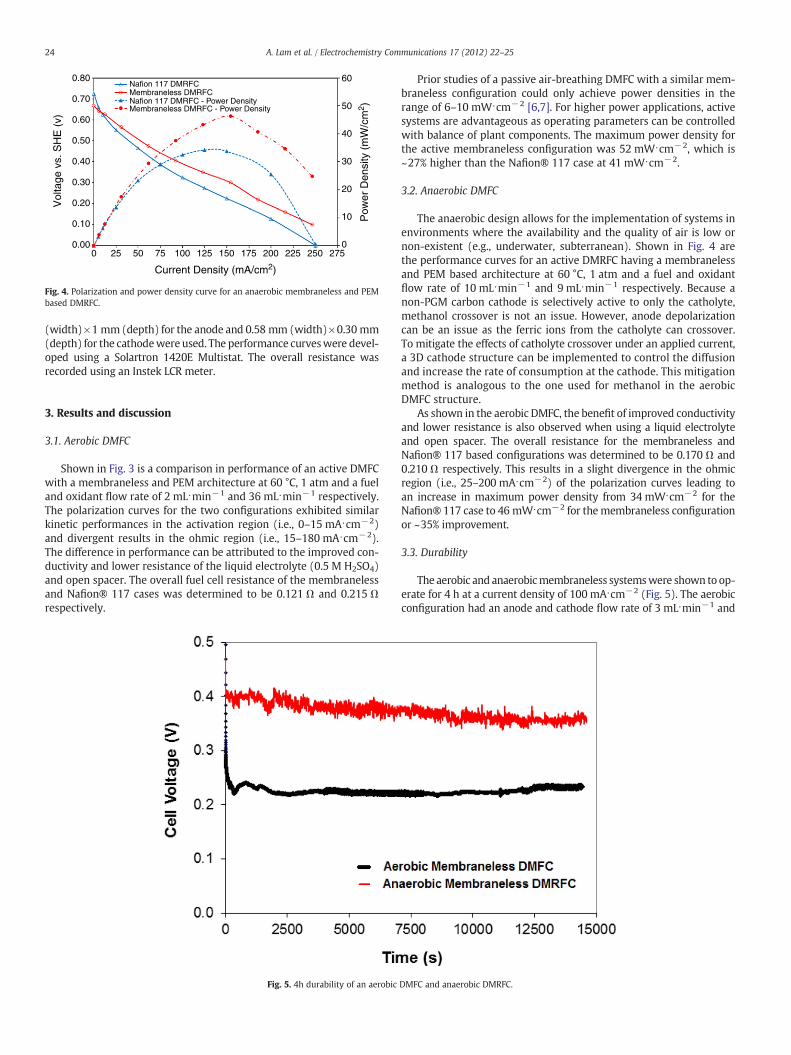
3.3. Durability
The aerobic and anaerobicmembraneless systemswere shown to op-erate for 4 h at a current density of 100 mA⋅cm−2 (Fig. 5). The aerobicconfiguration had an anode and cathode flow rate of 3 mL⋅min−1 and
DMFC and anaerobic DMRFC.

25A. Lam et al. / Electrochemistry Communications 17 (2012) 22–25
36 mL⋅min−1 respectively with a re-circulating fuel solution. The an-aerobic configuration had an anode and cathode flow rate of11 mL⋅min−1 and was operated in a single pass configuration (i.e., norecirculation).
The initial drop in voltage was as a result of the fuel cell reachingan equilibrium for the selected current density. The variability in theanaerobic configuration is caused by the formation and transport ofproduct gas in the electrode structure. The performance decreaseswhen the product gas blocks the access of liquid reactants to thecatalyst sites and recovers when it is removed. Better voltage stabilityis observed in the aerobic DMFC case.
4. Conclusions
The operational and architectural flexibilities of a membrane-less direct liquid fuel cell were demonstrated under aerobic andanaerobic configurations. The maximum power density for themembraneless DMFC was 52 mW⋅cm−2 and was shown to be~27% higher than the Nafion® 117 based DMFC case at41 mW⋅cm−2. The maximum power density for the membraneless
DMRFC configuration was 46 mW⋅cm−2 and was shown to be~35% higher than the Nafion® 117 based DMRFC case at34 mW⋅cm−2. Similar performances were achieved for both aero-bic (air) and anaerobic (Fe2+/Fe3+) systems and both wereshown to operate for 4 h. Significant opportunities exist for mem-braneless and anaerobic operation using different fuels.
References
[1] E. Kjeang, N. Djilali, D. Sinton, Journal of Power Sources 186 (2009) 6890.[2] M. Priestnall, V.P. Kotzeva, D.J. Fish, E.M. Nilsson, Journal of Power Sources 106
(2002) 21.[3] S. Barton, T. Patterson, E. Wang, T.F. Fuller, A.C. West, Journal of Power Sources 96
(2001) 329.[4] J.P. Meyers, H.L. Maynard, Journal of Power Sources 109 (2002) 76.[5] S. Motokawa, M. Mohamedi, T. Momma, S. Shoji, T. Osaka, Electrochemistry Com-
munications 6 (2004) 562.[6] A. Lam, D.P. Wilkinson, J.J. Zhang, Electrochimica Acta 53 (2008) 6890.[7] A. Lam, D.P. Wilkinson, J.J. Zhang, Electrochemistry Communications 11 (2009) 1530.[8] K. Fatih, D.P. Wilkinson, F. Moraw, A. Ilicic, F. Girard, Electrochemical and Solid-
State Letters 11 (2) (2008) B11–B15.[9] A.B. Illcic, M.S. Dara, D.P. Wilkinson, K. Fatih, Journal of Applied Electrochemistry
40 (2010) 2125.[10] A.B. Illcic, D.P. Wilkinson, K. Fatih, Journal of the Electrochemical Society 157
(2010) B529.