aerodynamic derivative measurements on a wing with...
TRANSCRIPT

iL~i, [ ; "J ~!!;?-
M I N I S T R Y OF A V I A T I O N
R. & M . N o . 3307
A E R O N A U T I C A L R E S E A R C H C O U N C I L
R E P O R T S A N D M E M O R A N D A
Aerodynamic Derivative Measurements on a W i n g with a Horn-Balanced
Control Surface
B y P . R . GUYETT a n d J . K . CURRAN
L O N D O N : H E R M A J E S T Y ' S S T A T I O N E R Y O F F I C E
I963
PRICE ISS. 6d. NET

Aerodynamic W i n g
By P.
Derivative Measurements with a Horn-Balanced Control Surface
¢,
t . GUYETT a n d J. K . CURRAN
on a
COMMUNICATED BY THE DEPUTY CONTROLLER AIRCRAFT (RESEARCH AND DEVELOPMENT),
I-V~INISTRY OF AVIATION
Reports and Memoranda No. 3307*
March, z96i
Summary.
Some oscillatory aerodynamic derivatives for wing pitch and translation, and control-surface rotation have been found from measurements in a low-speed wind tunnel. The wing was a modified cropped delta of biconvex circular-arc section having a small leading-edge radius and fitted with a horn-balanced control surface. The measurements covered a range of control-surface angles with the wing at a mean angle of incidence of 0%
Control-surface setting influenced the values of all derivatives but the variation was small for angles in the range 0 ° to 5 °. The wing lift and pitching-moment derivatives for wing motion at small control angles were in satisfactory agreement with theoretical results. Derivatives for control-surface rotation at small angles of the control were generally in reasonable agreement with values estimated using theoretical and semi-empirical methods.
1. Introduction.
Experiments1, 2 have shown that it is possible to predict with good accuracy the aerodynamic
forces acting at low subsonic speeds on oscillating wings having conventional subsonic-section
profiles. Large discrepancies can exist, however, between the corresponding measured and
calculated forces arising from control-surface motion 3, where viscous forces play a more significant
part, but are inevitably neglected in the theoretical analysis. Viscosity may also be expected to have
an important influence on the unsteady forces acting at low speeds on wings with sharp leading edges.
This report describes some oscillatory-force measurements made in a low-speed wind tunnel on a
modified cropped delta of biconvex circular-arc section with a small leading-edge radius and fitted
with a horn-balanced control surface. With this configuration the problems of predicting aerodynamic
forces due to control-surface movement are complicated by the flow through the gap between the wing and the horn. Results were obtained for the range of frequency parameter 0.27 to 1.1, the corresponding Reynolds numbers being between 1.4 x l0 s and 0.35 x 10⁶ respectively. Transition wires were fitted to both surfaces of the wing and control horn, at a distance of 25% of the local chord from the leading edge, for all test conditions, and in addition two series of control-surface oscillation tests were made with the wing bare.
Previously issued as R.A.E. Report No. Structures 263--A.R.C. 23,120.

Measurements were made of the wing lift and pitching moment for rigid wing pitch about a mean angle of incidence of 0 ° with the control surface set at angles of 0 ° to 15 ° to the wing. The
results show that both the stiffness and damping derivatives for lift and moment depended upon the
control setting. At 0 ° angle there was reasonable agreement with calculated derivatives.
Measurements were also made of the wing lift and pitching moment and of the control-surface
hinge moment for control-surface oscillations about mean angles of 0 °, 5 ° and 10 ° with the wing held
at 0 ° incidence. The derivatives showed only a small variation in changing the mean control angle
from 0 ° to 5 ° but generally increased in magnitude at a mean angle of 10% Results for control-surface
amplitudes of 4 ° and 8 ° were in fairly close agreement in each case with transition wires fitted.
Values of the derivatives for 0 ° mean angle were in reasonable agreement with theoretical results
and with values estimated using a semi-empirical method.
Attempts were made to examine the flow over the wing during oscillatory motion by photographing
tufts attached to the wing surface. With the control displaced the film records clearly showed airflow
oscillating through the gap opene d up at the root of the horn.
2. Method.
Aerodynamic derivatives for pitch and normal translation were found by measuring the lift and
moment during sustained pitching oscillations about two spanwise axis positions. The lift and
pitching moment were determined from the output of a force transducer in a linkage providing the excitation about the axis, and from the output of a force transducer measuring the lift at the axis.
Aerodynamic derivatives for control-surface rotation were found from measurements of the lift and pitching moment on the wing and of the control-surface hinge moment during sustained oscilla-
tions of the control with the wing fixed. The wing was fixed by two force transducers which provided restraint in pitch and normal translation and by the wing support frame which provided restraint in roll. A third force transducer was mounted in a driving linkage, normal to the plane of the wing,
wb_ich oscillated the control surface. Measurements of the reactions at the three force transducers enabled the wing lift and pitching moment to be found, and the control-surface hinge moment
was given directly by the force in the linkage. In each mode of oscillation the reactions of the inertia forces at the force measuring points were
reduced by mounting the wing, or the control surface, on a set of earthed springs. The springs were
arranged to give a balance between the stiffness and inertia forces at a chosen frequency of
oscillation, and this frequency was maintained throughout the tests. Frequency parameter was
varied by altering the wind speed. The method of calculating the required spring stiffnesses and positions has been described in
detail in Ref. 1. When a precise balance of stiffness and inertia force is obtained, the forces measured
in an oscillation in still air at the chosen frequency arise solely from the still-air aerodynamic damping
and the apparatus damping. If the wing is then oscillated in a windstream at the same frequency
and amplitude the additional forces measured, which in general are large compared with the still-air
forces, give directly the additional aerodynamic forces acting on the wing.
3. Apparatus.
3.1. Wind Tuwwl.
The tests were made in the R.A.E. 5 ft diameter Low-Speed Wind Tunnel. The working section

was dosed for these tests by fitting a circular-section tube between the entry nozzle and the safety screen. A fairing was added to the bottom of the tube to give a horizontal flat surface at the model
position.
3.2. Wing and Sz~pport. The half-span model wing was mounted vertically in the wind tunnel and was supported through
a slot in the fairing at the bottom of the circular tube. To reduce the air flow through this slot and
around the wing root a metal plate was fixed to the wing and oscillated with it. In addition wooden
strips were fitted on the fairing around the metal plate to form a shallow well. Fig. 2 shows the
position of the model in the tunnel. The horizontal flat surfaces normal to the wing at its root were
considered to act as a reflector plate to simulate symmetrical aerodynamic loading.
Dimensions of the wing and control surface are given in Fig. 1. The wing was of modified cropped
delta planform. Over the inboard wing the leading edge was swept back 38 °, and over the horn th~
leading edge was swept back 65 ° . Inboard of the horn the control-surface chord was constant and
equal to 27~ of the wing mean chord. The wing geometric aspect ratio was 1" 04, equivalent to a
full-span aspect ratio of 2.08. The wing section was a biconvex circular arc with a blunt trailing
edge of thickness equal to 0.4o// o of the chord, and with a roun ded leading edge of radius approximately
0.6°/o of the chord. The thickness/chord ratio was 0-04 for the inboard wing, and increased to
0-08 at the tip.
The main wing surface was made of sheet steel welded to spanwise steel webs and screwed and
riveted to solid steel members which formed the wing leading edge and root. The control surface
was moulded in Durestos, and attached to the wing by two plain bearings at the root of the wing
and the horn. Three Duralumin brackets were bolted to the wing root through the Duralumin reflector plate. A steel channel was bolted into the front or rear bracket and carried a cross-spring
bearing unit forming the pitching axis. The cross-spring bearing was bolted to a rectangular welded frame which in turn was attached to a further cross-spring bearing unit bolted to a vertical member in a heavy base frame. Fig. 3 shows the arrangement for wing pitch about the forward axis. A force transducer was connected between the base and the rectangular frame close to the pitching axis.
The output of this transducer was thus proportional to the lift force acting on the axis. The driving rod used to excite the pitching modes of oscillation was connected to the central root
bracket. Duralumin angles bridging the three brackets provided an attachment for the springs
required for balancing the inertia force. For the pitching-oscillation tests the control surface was
locked to the rear bracket by two studs at the root of the control surface which passed through slots
in the reflector plate. For the control-surface oscillations with wing fixed, the wing was supported
as shown in Fig. 3 but with a second force transducer connected between the rear bracket and an
adjacent rigid structure. The two force transducers thus measured the lift and pitching moment
acting on the fixed wing including the reaction at the control-surface hinge line. A metal plate was
bolted to the control-surface studs and the driving linkage was coupled to it between the rear
brackets. Springs were connected between the plate and earth and adjusted to cancel the inert ia
loads on the control-surface hinge and the direct inertia load in the exciter transducer.
3.3. Excitation.
In each mode the oscillation was maintained by forcing from a swash-plate exciter (Fig. 2). The
angle of tilt of the swash plate could be varied smoothly to alter the amplitude of oscillation of a
plunger projecting from the body of the exciter. Sinusoidal forcing from the plunger was transmitted
3
(s6213) A 2

through a spring and linkage to a driving rod coupled to the wing or control surface. Cross-spring bearings were used throughout to minimise the apparatus damping.
3.4. Frequency Measurement.
Balance between the spring and inertia forces occurs only at the chosen frequency, and thus to avoid errors in the force measurements this frequency must be accurately maintained.
Frequency was measured at 10 second intervals during the test and corrected by manually adjusting the speed of the exciter motor. An electronic counter ~ measured the frequency to an accuracy of about + 0- 05% and generally it was maintained to within + 0.1% of the chosen value.
3.5. Force Measurement and Recording.
Applied forces normal to the mean plate of the wing were measured by force transducers in the driving linkage and at the wing root. (Fig. 2 and Section 2.)
A force transducer is shown in Fig. 4. The ends of two beryllium copper strips were attached to a
channel section forming the body of the unit, and these strips were placed in tension by tightening
two bolts in a block connecting their centres. Load applied to the connector then caused an increase
in tension in one strip and a decrease in the other. Four wire-resistance strain gauges cemented to
the strips were connected to form a Wheatstone bridge sensitive to loading in the axial direction. Output from the galvanometer arm of the Wheatstone bridge was supplied to a pair of brushes
bearing at 180 ° on a two-segment commutator mounted on the shaft of the exciter and rotating at
the wing oscillation frequency. Each of the two commutator segments was coupled to an outer slip
ring which was connected to the galvanometer. The transducer output was thus reversed in direction
after each half cycle of oscillation by the commutator to produce a signal having a mean d.c. level
which was measured by the galvanometer. The transducer output could also be switched to a second
pair of brushes at 90 ° to the first pair. Fig. 5 indicates the arrangement of the commutator and
Fig. 6 the form of the resultant signals. It may be shown that for a sinusoidal input signal the two
galvanometer readings are:
Switched to 1st pair of brushes,
response = - -
Switched to 2nd pair of brushes,
2 S0cos ,
response = - S 0 sin~.
From these two readings the amplitudes of the transducer outputs and their phase relationships to
the commutator were found. The phase angle between the commutator rotation and the wing displacement depended upon the wing load since the exciting force was applied through a spring. To establish this angle a strain-gauged cantilever strip was connected to the wing or control surface
and its output also supplied to the commutator and measured by the galvanometer. The cantilever produced a signal in phase with the wing displacement and thus from the two sets of measurements
the components of the transducer output in phase and in quadrature with the wing displacement were found.
4. Test Procedure.
In each mode the reactions of the inertia forces at the force transducers were reduced by oscillating
the wing or control surface against earthed springs as described in Section 2. Generally a precise
balance of inertia and stifness force was not achieved but instead spring stiffnesses and positions
4
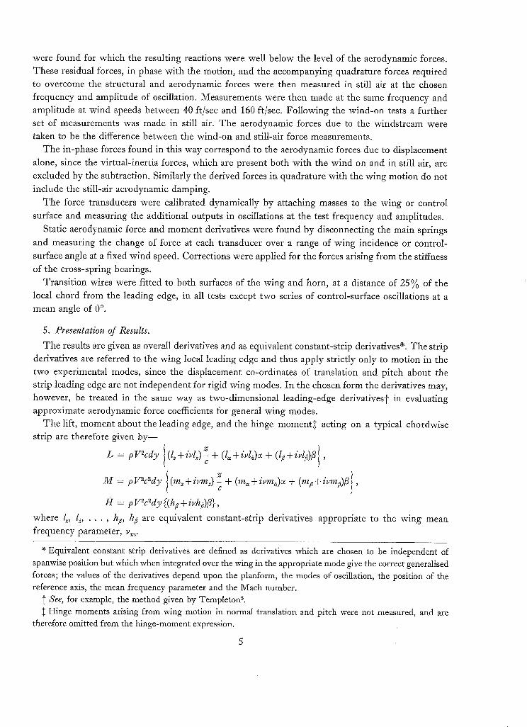
were found for which the resulting reactions were well below the level of the aerodynamic forces.
These residual forces, in phase with the motion, and the accompanying quadrature forces required to overcome the structural and aerodynamic forces were then measured in still air at the chosen
frequency and amplitude of oscillation. Measurements were then made at the same frequency and amplitude at wind speeds between 40 ft/sec and 160 ft/sec. Following the wind-on tests a further
set of measurements was made in still air. The aerodynamic forces due to the windstream were
taken to be the difference between the wind-on and still-air force measurements.
The in-phase forces found in this way correspond to the aerodynamic forces due to displacement
alone, since the virtual-inertia forces, which are present both with the wind on and in still air, are
excluded by the subtraction. Similarly the derived forces in quadrature with the wing motion do not include the still-air aerodynamic damping.
The force transducers were calibrated dynamically by attaching masses to the wing or control
surface and measuring the additional outputs in oscillations at the test frequency and amplitudes.
Static aerodynamic force and moment derivatives were found by disconnecting the main springs
and measuring the change of force at each transducer over a range of wing incidence or control-
surface angle at a fixed wind speed. Corrections were applied for the forces arising from the stiffness of the cross-spring bearings.
Transition wires were fitted to both surfaces of the wing and horn, at a distance of 25% of the
local chord from the leading edge, in all tests except two series of control-surface oscillations at a mean angle of 0 °.
5. Presentation of Results. The results are given as overall derivatives and as equivalent constant-strip derivatives e. The strip
derivatives are referred to the wing local leading edge and thus apply strictly only to motion in the
two experimental modes, since the displacement co-ordinates of translation and pitch about the strip leading edge are not independent for rigid wing modes. In the chosen form the derivatives may, however, be treated in the same way as two-dimensional leading-edge derivatives]" in evaluating approximate aerodynamic force coefficients for general wing modes.
The lift, moment about the leading edge, and the hinge moment+ + acting on a typical chordwise strip are therefore given by--
L pV2cdyl ( l~+ivL)z 1 = ~ + (l~ + ivl~)~ + (l~ + ivl~)~ ,
M pV2c2dyl(m~+" z l = zvm~) c + (m~ + ivma)o~ + (m# + ivm~)fi ,
H = p +
where l~, l~, . . . , hp, he are equivalent constant-strip derivatives appropriate to the wing mean frequency parameter, v m.
e Equivalent constant strip derivatives are defined as derivatives which are chosen to be independent of spanwise position but which when integrated over the wing in the appropriate mode give the correct generalised forces; the values of the derivatives depend upon the planform, the modes of oscillation, the position of the reference axis, the mean frequency parameter and the Mach number.
See, for example, the method given by Templeton 5. Hinge moments arising from wing motion in normal translation and pitch were not measured, and are
therefore omitted from the hinge-moment expression.

Now.
and it may be shown that,
C
C m
z = z' + ( c ' - c ) ~
% = 1-396 ft
c' = 2 .056 ft
s = 1 .45Of t
f l c d ~ = 0 .6789c ' , 0
J q c2&? = 0 .5115c '2, 0
f l c3d~ = O. 4088c '3. 0
By integrat ing the lift, moment , and hinge m o m e n t over the wing f rom root to tip, for rigid wing
mot ion in z ' , ~ and /? the fo l lowing results may be obtained:
Lif t z' . c ' z' pV2sc, - I. ~ + O" 3211l~ + 0. 6 7 8 9 / ~ + zv,,, ~ (0. 6789/~ )v + 0 ' 1674l~:~ +
C t
+ 0.5115/a~ ) + 0.6789/p/? + i v y . , - 0. 5115/¢fi, Cm
M o m e n t about root leading edge
Hinge m o m e n t D V2sc~ 2
O VZsc,2
~,t Zt = - 0 . 3 2 1 1 l ~ = + 0 .6789m~-~ - 0.1537loc~.. +
c ' c '
+ 0. 1674rn~c~ - 0. 1674l~c~ + 0 . 5 1 1 5 m ~ +
C~ ( Z t 2; t + iv~ - O" 1674/~ ~7 + O" 5115m~ c~ -
- O" 0647l~= + O. 1027m~ - O" 1027la~ +
+ 0 .4088ma@ + 0-5115m#fi - O. 1674/pfi +
C ~ + iv,~ - - (0 .4088m#fi - O. 1027l~fi),
C m
C¢ = 0.5115hpfi + i v ,~ - - 0.4088h~fi.
C m
5.1. Pitching about the Forward Axis with the Control Locked to the Wing.
yg'
C t - - - - 0 " 3 0 2 ~ , f i = 0 .

Hence, Lift c'
P V2sc,c ~ - O. 6789I~ + 0.0192l~ + iv,,, - - % ( - O. 0376l e + 0- 51151a)
C t
= (lo) / + i v , , , - (lo): , say. , C m
Pitching moment about root leading edge = _ 0. 056751, - 0. 1674l~ - 0. 03763* G + p U2SC'2O~
C / + 0.5115m~ + iv,,,.7~... ( - 0 . 0 1 4 1 l ~ - 0 . 1027la- 0-0518m~+ 0-4088ma)
/ / b
g'
= (too) / + i v , , , - (toO): , say. C m
T h e measured overall derivatives (lo)y, (10)/, (rno)/ and (m0) t are plotted against mean frequency
parameter in Figs. 9 and 10.
• Hence,
5.2. Pi tch ing about the Rear A x i s wi th the Contro l L o c k e d to the Wing•
- 0.7073~, fi = 0.
Lift c' P V~sc'o~ 0.6789l~ - 0. 3862/~ + i,,,,,~,,, ( - 0 . 3 1 2 8 I ~ + 0.5115la)
Ct = (lo) ,, + iv,,, - - (10),., say.
C m
Pitching moment about root leading edge =' 0-0734L~ - 0. 1674I~ - 0. 3128m.,, + p V2sc ' %,
C' + 0" 5115m~ + iv, , - - (0' 0537l,j - 0. 1027l a - 0" 2591m~ + 0- 4088ma)
C m Ct
= (mo) r + i v , , , - (m0)r, say. c m
The measured overall derivatives (lo),., (Io),., (m0) ,, and (too),: are plotted against mean frequency
-parameter in Figs. 11 and 12.
5.3. Control Oscil lation with W i n g HeM.
Hence Li f t c'
pV~sc, fi - 0. 6789l: + iv,,, --c,,, 0. 5115l~
Pitching moment about root leading edge
pV2sc'2~ C r
+ ~V m - - C m
Hinge moment c' = 0.5115h d + i v , , - - 0.4088h~.
p V 2 s c ' 2 f i C m
= 0.5!15m/~ - 0. 16741/~ +
(0. 4 0 8 8 m : - 0. 1027l/~)
T h e measured values of these derivatives are plotted against mean frequency paran:eter in Figs. 17 to 25.

5.4. Equivalent Constant-Strip Derivatives.
From the curves in Figs. 9 to 12 the individual derivatives l~, l~ . . . . , ma have been found and are plotted against mean frequency parameter in Figs. 13 to 16.
Similarly the derivatives m~ and m¢ have been found from the results given in Figs. 17 and 18,
20 and 21, 23 and 24 and are plotted against mean frequency parameter in Figs. 26 to 28.
6. Discussion of Results and Comparison with Theory.
6.1. Corrections for Rig Deformation.
In oscillations in still air the amount of deformation was negligible, but with the wind on deformation Occurred consisting primarily of twist of the rectangular root frame due to the aero-
dynamic rolling moment. Since any change of mode alters the balance between the inertia and spring
reaction forces, as well as introducing additional aerodynamic forces, calculations were made for
each configuration at the maximum test speed to assess these effects. A sample calculation is described in the Appendix. The average correction to the values of the overall derivatives was
O / . approximately 1% with a maximum of 3.3/o, as these corrections are small they have not been applied to the results.
6.2. Corrections for Wind- Tunnel Wall Constraint.
Static wind-tunnel corrections for the test configuration, calculated from the results of Ref. 1,
indicate that the measured stiffness derivatives at low frequency parameters are about o r ~ 1 O//o higher
than the free-stream values. From the existing results 6, 7 for oscillating wings in closed wind tunnels
the corrections to the stiffness derivatives are greatest at low frequency parameter and the
corrections to damping derivatives are small. Thus the measured derivatives are probably subject
to only small errors from wall constraint, and are therefore given without any corrections applied.
6.3. Pitching Oscillations about the Forward Axis.
Wing lift and moment derivatives for each setting of the control surface are plotted against
frequency parameter in Figs. 9 and 10. Derivatives which have been calculated by Bristol Aircraft
Ltd., using the Multhopp-Garner method are given for comparison. Also shown are some values obtained by interpolation from results calculated by LehrianS; these apply to a cropped delta of the same aspect ratio as the test wing.
The derivatives for 0 ° relative angle between control and wing show little variation with frequency
parameter, and are in reasonable agreement with the theoretical values. Increasing the aileron-wing
angle in the range 0 ° to 10 ° generally increased the magnitude of the stiffness lift and moment derivatives. A further increase of angle to 15 ° reduced their magnitude but they remained above the
values for 0 ° angle. The trends of change of the damping-force derivatives are less clear. At 5 ° angle the derivatives are rather larger in magnitude than at 0°; at 10 ° and 15 ° they are markedly dependent upon frequency parameter.
Altering the control setting at the constant test-wing mean incidence of 0 ° produced steady loads
on the wing, and thus may be regarded as equivalent in some respects to changing the wing mean
incidence. Scruton ~ has measured the effect of mean wing incidence on the corresponding oscillatory
derivatives for a cropped delta wing. His results also show increases in the magnitude of stiffness force derivatives for small increases of incidence and reductions at larger incidence, and indicate
that the damping-force derivatives varied with mean incidence and frequency parameter at high incidence.

Some cine-film camera records were taken of the behaviour of tufts fixed to the wing surface to obtain an indication of the flow conditions during steady and oscillatory wing motion. The tufts
moved regularly with wing displacement at the test frequency and it is believed that they provided a fairly accurate qualitative picture of the flow directions. With the control deflected the records clearly showed flow o scillating through the gap opened up between the horn and the wing. At the largest angles the tufts indicated breakaway over the suction surface of the control between the root of the horn and the wing root, with the flow attached over part of the surface of the horn itself. Fig. 8 shows a sequence of camera pictures of the outer wing and horn covering rather more than one-quarter of a cycle of wing oscillation. The control surface was fixed to the wing at an angle of 7½ ° and the wing was oscillated through + 3 ° about a mean incidence of 0 °. In frame 1 the tufts all lie in the streamwise direction (with the exception of the third tuft at the horn root which had become
fixed at the transition wire). As the wing was displaced the tufts at the front of the horn at its root curled into the gap, and the tuft at the tip leading edge of the horn was drawn over the tip. In frame
3 the tuft on the horn at the rear of the gap is also curled into the gap and the second tuft from the
tip is drawn over the leading edge. Subsequent pictures show the tufts on the wing near the gap curving towards the gap.
The existence of an oscillatory flow through the horn gap is not unexpected and could give rise
to the measured effects of frequency parameter upon the magnitude of the derivatives. In the tests
the phase angles between the resultant oscillatory force and displacement vectors were between
10 ° and 20 °, and thus a small change of phase angle, which could be produced by the gap and depend
upon the frequency parameter, would have a greater influence upon the damping forces than the stiffness forces. An explanation can therefore be found for the measured results, but it is considered extremely unlikely that they can be predicted in detail.
The generally good agreement between the two sets of theoretical results suggests that the derivatives do not vary greatly with frequency parameter or depend critically upon the planform.
6.4. Pitching Oscillations about the Rear Axis.
The measured results are plotted in Figs. 11 and 12 together with the theoretical values. The stiffness derivatives for 0 ° aileron angle are practically independent of frequency parameter
over the test range; the corresponding damping derivatives increase slightly with frequency parameter. Both sets of derivatives are in reasonable agreement with the theoretical values.
The stiffness derivatives show the same trend of change with aileron angle that occurred at the forward axis position, and again the damping derivatives show only a small variation with aileron angle in the range 0 ° to 5 °.
6.5. Wing Lift and Moment Derivatives.
From the results in Figs. 9 to 12 and the relations in Section 5 equivalent constant-strip derivatives referred to the local leading edge have been found and are given in Figs. 13 to 16.
The rates of change of the pitching derivatives (Figs. 15 and 16) with aileron angle are generally smaller than the corresponding changes of the translation derivatives (Figs. 13 and 14).
6.6. Wing Lift and Moment and Aileron Hinge Moment due to Aileron Rotation.
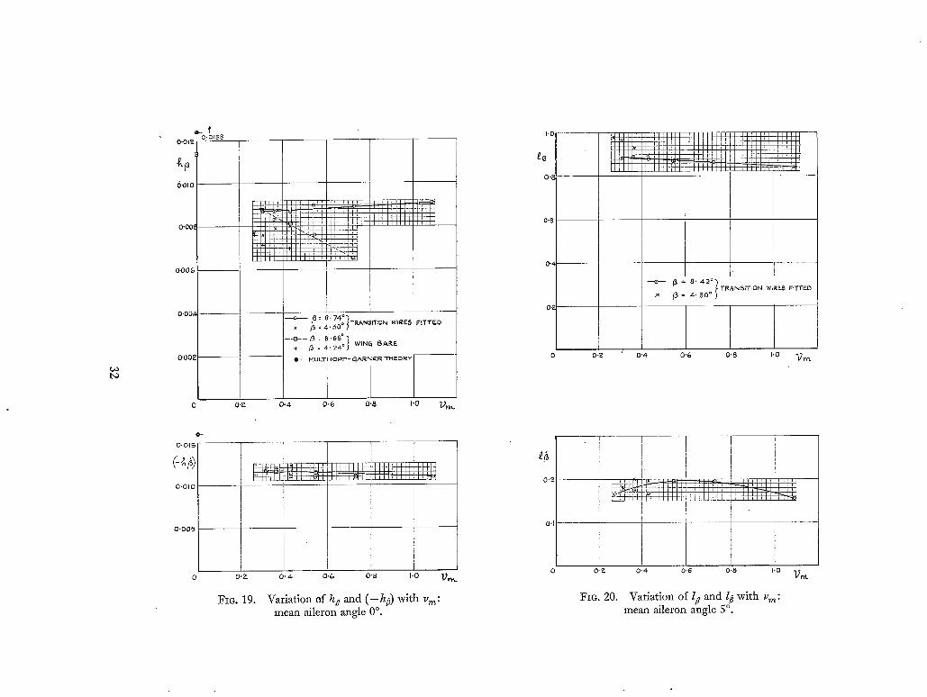
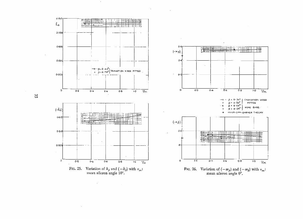
Results for a mean aileron angle of 0 ° are given in Figs. 17, 18, 19 and 26. The derivatives lp and m d are largely independent of frequency parameter, aileron amplitude and the transition point
9

within the ranges considered. The corresponding damping derivatives l~ and rn3 show some dependence upon amplitude with the transition fixed and a marked dependence upon amplitude for
free transition. In both conditions the values of the damping derivatives fall as the frequency parameter is reduced below 0.4. The hinge-moment damping derivative hp is practically independent of frequency parameter, amplitude and the transition point. The stiffness derivative h/~ also shows only a small variation with frequency parameter for transition fixed but depends to some extent upon
amplitude. For free transition h~ varies with both amplitude and frequency parameter. Figs. 20, 21, 22 and 27 show the results for a mean aileron angle of 5 ° and fixed transition. In the
test range, the derivatives vary only slightly with amplitude although the variation is more marked on the stiffness derivatives than on the damping derivatives. In general the values and trends agree fairly well with those for 0 ° mean aileron angle. An exception is h/3 which decreases with increasing
frequency parameter. At 10 ° mean aileron angle (Figs. 23 to 25 and 28) the derivatives are larger in magnitude than at
0 ° and 5 °, and l# and m3 in particular show" more variation with frequency parameter. Again the
changes with amplitude are fairly small. Film records of the movement of tufts fitted to the wing and aileron indicated that there was
airflow through the gap between'the front of the horn and the wing during the aileron oscillations.
This flow was apparently small at a mean aileron setting of 0 °. The lift and pitching-moment derivatives calculated by the Multhopp-Garner method are in
generally good agreement with the measured resuks. The corresponding damping hinge-moment
derivatives are also in reasonable agreement for the smaller control settings. There is, however, a large discrepancy between the calculated and measured stiffness hinge moments, where the
experimental results indicate that the derivative is sensitive to the conditions in the boundary layer. It is of interest to compare the measured derivatives with results calculated on a simple theoretical
basis. Figs. 29 to 31 show the derivatives for a mean aileron angle of 0 ° and transition fixed together
with some calculated values. In finding each set of calculated derivatives the aerodynamic forces on the horn were assumed to be given by slender-body theory--the horn being treated as half of a full-span cropped delta. To obtain the wing lift and moment results in Figs. 29 and 30 the wing inboard of the horn was divided into four chordwise sections of equal width and forces appropriate to the local frequency parameter and chord ratio were found for each section using first two-
dimensional 9 and then finite aspect-ratio wing derivatives. The finite wing derivatives used were equivalent constant strip derivatives for a rectangular wing of aspect ratio 2 (practically equal to the test-wing aspect ratio) with a full-span control surface, which were calculated by Minhinnick from work by Lawrence and Gerber l°. The measured values of I/~ and 13 are in fairly good agreement with the results calculated using finite aspect-ratio theory for the inner wing but are in poor agreement with the corresponding results using two-dimensional theory. The measured damping derivative, however, shows the same trend at low-frequency parameters as the results using two-dimensional theory. Fig. 30 shows that the measured values for the stiffness moment derivative m/~ are rather larger than the calculated values using finite-wing theory, which indicates that this method of calculation, in addition to slightly underestimating the magnitude of the lift in phase with the
motion also underestimates the distance of its mean centre of pressure from the wing leading edge. Curves of the damping moment derivative are similar in trend to those for the damping lift derivative. Values for the hinge-moment derivatives are compared in Fig. 31. Forces on the control surface inboard of the horn were found by dividing the inboard wing into sections as before and using
10

factored and unfactored two-dimensional hinge-moment derivatives. The factor used was 0.6
which was found by Wight 3 to be approximately the ratio of the measured to the theoretical value of the direct aileron derivatives from tests on a 15% thick wing with a 20% chord aileron in two- dimensional flow. Applying this factor increases the resultant value of h# since the in-phase moment
from the horn is larger than and opposes the stabilising moment from the inboard control. The results show that a factor of value 0.8 would give excellent agreement between the measured and estimated derivatives, and since the test wing is thinner and has a smaller trailing-edge angle
(about 8 °) than the wing tested by Wight (15 °) a higher value for the factor is probably appropriate.
For the damping hinge moment better agreement would be obtained if the value of the factor was
smaller than 0.6. There is some evidence a that h~ is less sensitive to trailing-edge angle than h/~ and
thus there is no reason why the values of the factors should be identical.
In general, the derivatives calculated using the semi-empirical methods described are in reasonable
agreement with the measured values. The order of agreement is better than that obtained using the theoretical method which does not take into account wing thickness and flow through the horn-wing
gap. It is doubtful if the corresponding forces for large mean aileron angles can be predicted satisfactorily.
7. Conclusions.
The results of a series of measurements of oscillatory aerodynamic derivatives at low wind speeds on a modified cropped delta having a biconvex circular-arc section with a small leading-edge radius, and fitted with a horn-balanced control surface, show that:
(i) The wing lift and pitching-moment derivatives for wing pitch and translation about wing mean angles of incidence of 0 ° depend upon the setting of the control surface. For 0 ° angle between wing and control the lift and moment stiffness derivatives are practically independent of frequency parameter in the test range 0.3 to 0.7, and the corresponding variation in the damping derivatives is small. The values agree fairly well with theoretical results. As the control angle is increased from 0 ° to 10 ° the stiffness derivatives increase in magnitude but fall with a further increase to 15 °.
The damping derivatives change to a small extent as the control-surface angle is increased fl'om 0 ° to 5 ° but at larger angles vary considerably with angle and frequency parameter.
(ii) With transition wires fitted to the y~ing and control horn at 25 % of the local chord aft of the
leading edge, and with the wing held at 0 ° incidence, the lift, pitch and hinge-moment stiffness derivatives for control oscillations about a mean angle of 0 ° are largely independent of frequency
parameter in the test range 0.3 to 1.1. The corresponding hinge-moment damping derivative is also independent of frequency parameter but the values of the lift and pitching-moment damping derivatives fall as frequency parameter is reduced below 0.4. All derivatives show only small changes in value as the mean angle increases to 5 ° but have larger values at 10 ° mean angle. Measurements at control-surface amplitudes of approximately 4 ° a n d 8 ° gave generally similar results in all cases. The derivatives for control-surface motion at small angles of the control are in
reasonable agreement with values calculated using theoretical and semi-empirical methods. A limited series of tests with natural transition indicate that certain of the derivatives are sensitive to oscillation amplitude and frequency parameter in this condition.
11
S O
C
Ct
017~
S
Y
dy
2;
L
M
H
40
V
Jd ~%
l~, l~., I/~
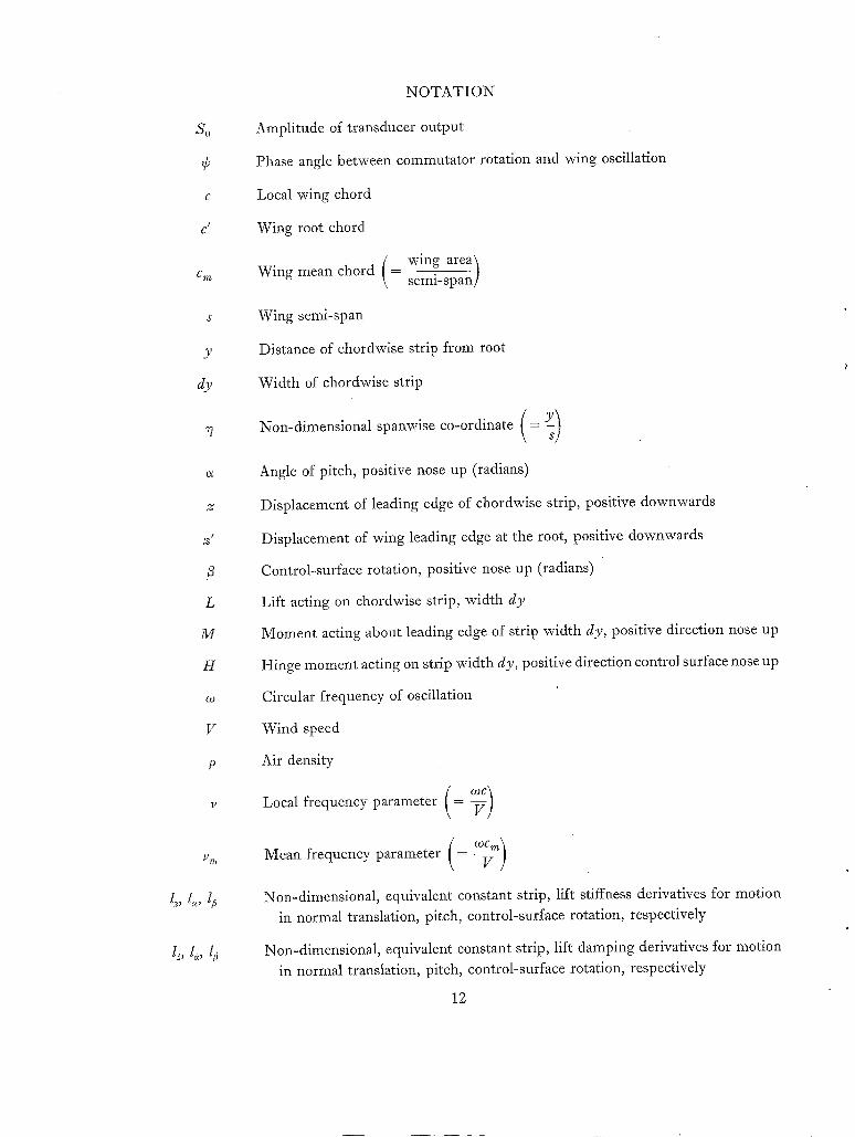
NOTATION
Amplitude of transducer output
Phase angle between commutator rotation and wing oscillation
Local wing chord
Wing root chord
wing area t Wing mean chord (= semi-span/
Wing semi-span
Distance of chordwise strip from root
Width of chordwise strip
Non-dimensional spanwise co-ordinate ( = y )
Angle of pitch, positive nose up (radians)
Displacement of leading edge of chordwise strip, positive downwards
Displacement of wing leading edge at the root, positive downwards
Control-surface rotation, positive nose up (radians)
Lift acting on chordwise strip, width dy
Moment acting about leading edge of strip width dy, positive direction nose up
Hinge moment acting on strip width dy, positive direction control surface nose up
Circular frequency of oscillation
Wind speed
Air density
Local frequency parameter (= V )
Mean frequency parameter ( = ~-~-V m )
Non-dimensional, equivalent constant strip, lift stiffness derivatives for motion in normal translation, pitch, control-surface rotation, respectively
Non-dimensional, equivalent constant strip, lift damping derivatives for motion in normal translation, pitch, control-surface rotation, respectively
12

mz, me, I,l~p
m~, me, m:
h:
h:
(mo)/
(too):
(zo)r
too),
(mo)r
NOTATION--contlnued
Non-dimensional, equivalent constant strip, pitching-moment stiffness deriva-
tives for motion in normal translation, pitch, control-surface rotation, respectively
Non-dimensional, equivalent constant strip, pitching-moment damping deriva- tives for motion in normal translation, pitch, control-surface rotation, respectively
Pitching moment measured about leading edge of local strip, positive nose up
Non-dimensional, equivalent constant strip, hinge-moment stiffness derivative for motion in control-surface rotation
Non-dimensional, equivalent constant strip hinge-moment damping derivative for motion in control surface rotation. Hinge moment positive direction control surface nose up
Non-dimensional, overall lift stiffness derivative for pitching motion about forward axis position ( = 0. 6789/~ + 0.0192/~)
Non-dimensional, overall lift damping derivative for pitching motion about forward axis position (= - 0. 0376/~+ 0. 5115/e)
Non-dimensional, overall moment stiffness derivative for pitching motion about forward axis position (= - 0. 05675/~- 0. 1674/~- 0. 03763m~+ 0. 5115m~)
Non-dimensional, overall moment damping derivative for pitching motion about forward axis position ( = - 0. 0141/e- 0. 1027/e- 0.0518m~ + 0.4088ma)
Non-dimensional, overall lift stiffness derivative for pitching motion about the rear axis position ( = - 0. 6789/~- 0. 3862/~)
Non-dimensional, overall lift damping derivative for pitching motion about the rear axis position ( = - 0.3128/~ + 0.5115le)
Non-dimensional, overall moment stiffness derivative for pitching motion about rear axis position ( = 0. 0734/~- 0. 1674/~ - 0.3128m~ + 0.5115m~)
Non-dimensional, overall moment damping derivative for pitching motion about rear axis position ( = 0. 0537l~ - 0. 1027l a - 0.2591m~ + 0.4088ma)
13

No. Author
1 P.R. Guyett and J. K. Curran ..
2 C. Scruton, L. Woodgate and A. J. Alexander
3 K.C. Wigt~t . . . . . .
4 W . D . T . Hicks . . . . . .
5 H. Templeton . . . . . .
6 W.P . Jones . . . . . .
7 W.E. Acum and H. C. Garner .
8 Doris E. Lehrian . . . .
9 I. Minhinnick . . . .
10 H.R. Lawrence and E. H. Gerber
R E F E R E N C E S
Title, etc.
Aerodynamic derivative measurements on a rectangular wing of aspect ratio 3' 3.
A.R.C.R. & M. 3171. March, 1958.
Measurements of the aerodynamic derivatives for swept wings of low aspect ratio describing pitching and plunging oscillations in incompressible flow.
A.R.C.R. & M. 2925. October, 1953.
Measurements of two-dimensional derivatives on a wing-aileron- tab system with a 1541 section aerofoil. Part II--Direct tab and cross aileron-tab derivatives.
A.R.C.R. & M. 3029. March, 1955.
An electronic instriament for the accurate measurement of the frequency of structural oscillations.
A.R.C. 17,920. January, 1955.
The technique of flutter calculations. A.R.C.C.P.172. April, 1953.
Wind tunnel interference effects on the values of experimentally determined derivative coefficients for oscillating aerofoils.
A.R.C.R. & M. 1912. August, 1943.
Approximate wall corrections for an oscillating swept wing in a wind tunnel of closed circular section.
A.R.C.C.P.184. January, 1954.
Calculation of flutter derivatives for wings of general planform. A.R.C.R. & M. 2961. January, 1954.
Subsonic aerodynamic flutter derivatives for wings and control surfaces (compressible and incompressible flow).
A.R.C. 14,228. July, 1950. (Addendum and Corrigendum in 14,855).
The aerodynamic forces on low aspect ratio wings oscillating in an incompressible flow.
J. Ae. Sci. Vol. 19. No. 11. November, 1952.
14

APPENDIX
Estimates of the Corrections to the Measured Derivatives Arising fi'om Rig Deformation
The deformation was not measured during the tests but from observation it was clear that the
primary mode was twist of the root frame. This mode was therefore chosen, together with displace- ment at the root transducer(s), and the prescribed wing or control motion, to define a system with a limited number of degrees of freedom. Lagrangian equations were then set up and solved to establish the amplitudes in each degree of freedom. From these results the corrections to the measured derivatives were found. The procedure for wing pitch about the forward axis position is described below.
The wing and support system are shown in Fig. 7.
The co-ordinates are
0 Angle of pitch, positive wing nose up,
¢ Angle of roll, positive wing tip down,
z Displacement of the wing in normal translation, positive downwards.
Coefficients in the Lagrangian equations were obtaiued as follows:
Inertia coefficients: these were found directly from measurements of the weight of the wing, support and excitation systems.
Stiffness coefficients: the stiffness forces arose from the displacement of the inertia balancing springs, the spring bearings in the system, and the twist of the root frame. For convenience, the transducer
coupling the root frame to earth was also treated as a spring.
Generalised force coefficients:
(a) Excitation forces: the exciter provided a force of known amplitude and phase angle in relation to the displacement of the cantilever strip attached to the wing; thus the excitation force,
F = (F' + iF")e i~)~
where F ' and F" are, respectively, the in-phase and in-quadrature components of force. Now the displacement of the exciter rod = alO + bl~ + z, where a 1 and b~ are the distances of the exciter rod behind the pitch axis, and above the roll axis, respectively. Hence the generalised forces are:
Fo = Fal Y¢ = Fb 1 F~= F.
(b) Aerodynamic forces: approximations to the aerodynamic forces acting in the chosen modes arising from the pitching motion were found from the uncorrected derivatives and an assumed position for the spanwise centre of pressure. The remaining forces, lift, pitching moment and roiling moment due to translation and roll, were ignored in order to simplify the analysis% Thus the generalised forces may be written:
Qo = G(mo + ivmo) O, =
Q~ = (C,+iB~)O, where G, C¢, C~, B z are known, and m o and m 0 are the required, corrected, pitching-moment derivatives.
*It was later shown that for the calculated amplitudes the aerodynamic forces arising from the motion in translation and roll were negligible in comparison with the forces due to pitch.
15
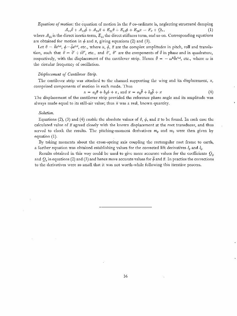
Equations of motion: the equation of motion in the 0 co-ordinate is, neglecting structural damping
&lO + + + EI O + + = Fo + Qo, (1) where A~I is the direct inertia term, Ell the direct stiffness term, and so on. Corresponding equations
are obtained for motion in ¢ and z, giving equations (2) and (3). Let 0 = Oe i~t, ~ = ~e i~t, etc., where ~, ¢, 2 are the complex amplitudes in pitch, roll and transla-
tion, such that 0 = 0' + iO", etc., and 0', 0" are the components of 0 in phase and in quadrature,
respectively, with the displacement of the cantilever strip. Hence 0 = - co~0e i~t, etc., where co is
the circular frequency of oscillation.
Displacement of Cantilever Strip.
The cantilever strip was attached to the channel supporting the wing and its displacement, x, comprised components of motion in each mode. Thus
x = a 2 0 + b ~ ¢ + z , a n d ~ = a z O + b ~ ¢ + 2 (4) The displacement of the cantilever strip provided the reference phase angle and its amplitude was always made equal to its still-air value; thus 2 was a real, known quantity.
Solution.
Equations (2), (3) and (4) enable the absolute values of 0, ¢, and 2 to be found. In each case the calculated value of 2 agreed closely with the known displacement at the root transducer, and thus served to check the results. The pitching-moment derivatives m o and m o were then given by equation (1).
By taking moments about the cross-spring axis coupling the rectangular root frame to earth, a further equation was obtained establishing values for the corrected lift derivatives 1 o and l 0.
Results obtained in this way could be used to give more accurate values for the coefficients Q¢ and Q~ in equations (2) and (3) and hence more accurate values for ¢ and 2. In practice the corrections to the derivatives were so small that it was not worth-while following this iterative process.
16
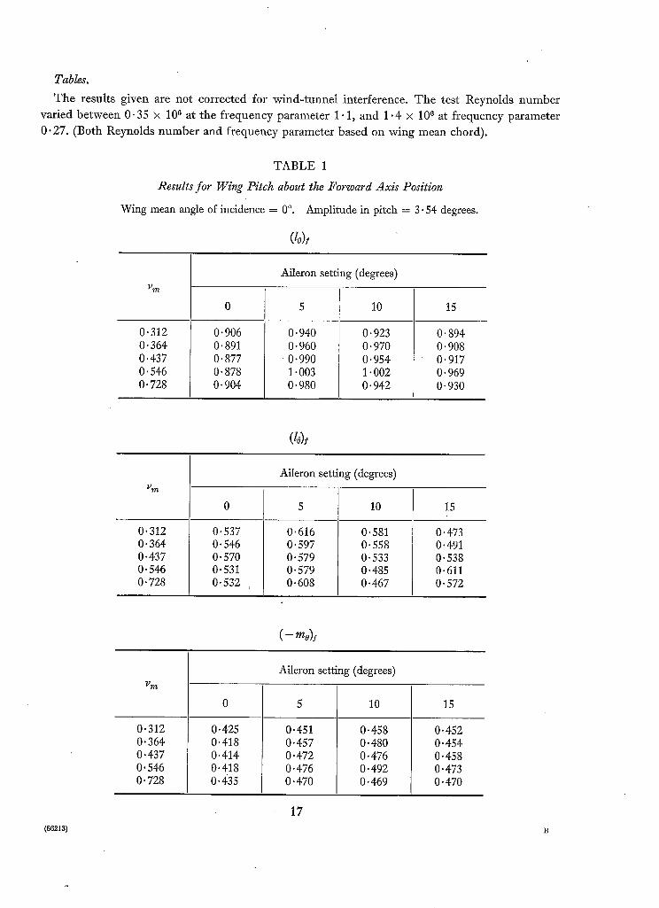
Tables.
T h e results given are not corrected for wind-tunnel interference. Th e test Reynolds number
varied between 0.35 ~× 106 at the f requency parameter 1.1, and 1 "4 × 10⁶ at f requency parameter
0.27. (Both Reynolds number and frequency parameter based on wing mean chord).
T A B L E 1
Results for Wing Pitch about the Forward Axis Position
Wing mean angle of incidence = 0 °. Amplitude in pitch = 3- 54 degrees.
(lo)l
Aileron setting (degrees) v ~
0 5 10 15
0.312 0.364 0.437 0.546 0.728
0.906 0.891 0.877 0.878 0-904
0-940 0.960
0 . 9 9 0 1.003 0.980
0.923 0.970 0.954 1.002 0.942
0.894 0.908 0.917 0.969 0.930
Aileron setting (degrees) vgF/,
0 5 10 15
0.312 0.364 0.437 0. 546 0.728
0.537 0. 546 0.570 0.531 0.532
0.616 0.597 0.579 0.579 0.608
0.581 0.558 0.533 O. 485 0.467 )
( -
Aileron setting (degrees) v~t .
0 5 10 15
O. 473 0.491 0.538 0.611 O- 572
( 86218 )
0.312 0"364 0.437 0" 546 0" 728
0.425 0.418 0.414 0"418 0.435
0.451 0.457 0.472 0.476 0.470
0.458 0.480 0.476 0.492 0.469
0"452 0"454 0"458 O" 473 0.470
17

T A B L E 1--continued
(-m6)i
Aileron setting (degrees)
0 5 10 15
0.312 0. 364 0.437 0. 546 0.728
0"339 0. 344 0.354 0.335 0.339
0. 377 0" 366 0-354 0- 362 0. 362
0.356 0. 348 0.339 0" 321 0. 308
0.314 0. 322 0-335 0. 363 0.352
T A B L E 2
Results for Wing Pitch about the Rear Axis Position
Amplitude in pitch = 2- 78 degrees. Wing mean angle of incidence = 0 °.
(G
Aileron setting (degrees) Vy(~
0 5 10 15
0.312 0.364 0.437 0" 546 0-728
O- 886 O. 892 0.888 O. 893 O. 887
0.945 0.942 0- 921 0.900 0.911
0.986 O. 949 O. 943 O. 922 O. 940
0-919 0.916 0.896 0. 891 0.902
(G
Aileron setting (degrees) P~
0 5 10 15
0-312 0-364 0.437 0.546 0.728
0.241 0.251 0- 249 0.263 0.286
0.230 0.244 0.243 0.247 0.260
0.167 0.186 0.216 0.260 0.319
0.131 0.151 0.167 0-198 0.245
18

T A B L E 2--continued
( - mo)
Vm
0.312 0.364 O. 437 O. 546 O. 728
Aileron setting (degrees)
0.413 0-415 0-414 0.413 0-413
0.440 0.438 O. 429 0.418 O. 426
10
0.468 0.451 O. 448 0.439 O- 447
15
0.430 O. 429 0.417 0-414 0.421
( - - mO) r
Aileron setting (degrees)
vm 0 5 10 15
0.312 O. 364 0.437 O- 546 0-728
O. 201 O. 208 0.210 O. 222 0.236
O. 196 O. 204 O. 203 O. 204 0.213
0.158 0. 169 0. 184 0-210 0-246
, O. 133 O- 145 0-154 O. 175 O. 205
19
(88213) B*

T A B L E 3
Results for Control-Surface Oscillations with Wing Fixed
Wing angle of incidence = 0 °.
Mean aileron angle (degrees)
0 without
transition wires
0 with
transition wires
5 with
transition wires
10 with
transition wires
degrees 4.24 8.65 4'30 8.74 4.30 8.42 4.18 8.42
v m lg
0.273 0.312 0.364 0.437 0.546 0.728 1.092
0.273 0.312 0'364 0.437 0.546 0.728 1-092
0.273 0.312 0.364 0.437 0.546 0.728 1.092
0.273 0.312 0.364 0.437 0.546 0-728 1.092
0.902 0.891 0-898 0.897
m
0.919 0-926 0.933 0.925 0.909
0.850 0.865 0-861 0.856
0-889 0.895 0.887 0.891 0.910 0.903
0.983 0-969 0.932 0.902
m
0.880 0-889 0.881 0.872 0.865 0.839
0.987 1.001 0-989 1.004
m - - - - m
0-983 0.993 0.990 0.992 0.946 0.952
0.227 0.222 0.211 0.167
0.137 0.154 0.184 0-165 0.161
0.122 0.197 0.201 0-225
0.160 0.188 0.175 0.194 0.180 0.178
0.164 0.183 0.200 0-199
m
0.176 0.173 0-167 0-196 0.195 0.155
0.140 0.193 0.241 0-232
- (0.5115m - 0-1674l/~)
0.145 0.181 0-197 0-204 0.247 0.238
0.431 0.427 0.430 0.431
0.440 0.443 0-448 0-442 0.437
0.407 0.415 0-413 0-413
0.426 0-431 0-428 0"428 0"439 0"437
0"473 0"467 0"447 0-432
0"420 0"425 0-423 0-418 0"414 0"405
0'473 0.482 0"476 0"485
_ _ m
- (0" 4088~t~ i - 0' 10271~)
m
0.473 0.479 0.477 0-479 0-456 0-462
0.1012 0.0996 0.0936 0-0786
0.0674 0.0748 0.0879 0-0779 0.0787
0.0696 0.0888 0.0903 0.0996
0.0772 0.0906 0.0860 0-0901 0.0863 0.0841
0.0822 0.0868 0.0947 0.0943
m
0.0822 0.0798 0.0809 0.0898 0.0888 0.0738
0.0740 0.1103 0.1175 0.1098
0.0759 0.0867 0.0923 0.0930 0.1095 0.1035
20

T A B L E 3--continued
Wing angle of incidence = 0 °.
Mean aileron angle (degrees)
0 without
transition wires
0 with
transition wires
5 with
transition wires
10 with
transition wires
i
/5 degrees 4.24 8.65 4.30 8"74 4-30 8.42 4.18 8.42
0-273 0-312 0-364 0-437 0.546 0.728 1.092
0-273 0-312 0.364 0.437 0-546 0.728 1.092
0.0076 0.0071 0.0070 0.0070
0"0088 0.0083 0.0081 0.0076 0.0065
0.0077 0.0076 0.0079 0.0080
0.0087 0.0087 0.0087 0.0090 0.0089 0.0091
0-0092 0-0089 0.0094 0.0091
0-0086 0-0085 0.0077 0-0082 0-0077 0.0072
0.0098 0.0092 0.0096 0.0091
(-h D
0.0093 0.0092 0.0091 0.0099 0.0089 0.0096
0.0112 0.0115 0.0119 0.0116
0.0117 0.0116 0.0109 0.0114 0.0109
0.0124 0.0117 0.0119 0.0122
0.0120 0.0115 0.0113 0.0109 0.0113 0.0109
0.0131 0.0133 0.0137 0.0140
m
0.0125 0-0121 0-0120 0-0124 0.0120 0.0118
0.0152 0-0147 0-0149 0-0134
0.0136 0.0131 0.0137 0.0140 0.0143 0.0159
21

bO I'O
15.00"
o 6
PITCHING ~ /
_ A = REFLECTOR / J - - ~-I I~
PLATE \ 1 z*.~7" - \
L
CONTROl.. ~ I
TYr~ICAL 5E.CTI0 N 5HOWING
Fie,. 1.
::::;::1
C 0 N T ~ 0 1 - - $URFACE N I N a E - - L I N E GAP
Wing and control-surface dimensions.
1 INIERTIA ~ A / A N E I N I ~
5PRINC T /
EXCITER / FI LTEBIN~, 5PRIN~
INERTI I
- WI /I I:k ..:#~gg~E~-- "x 1 .[:
Y I I',1 ' ' , ~ I A L ' ~ u ~ " \ \ \ \ \ \ X , \ \ \ \ X ' \ \ \ \ \ \ \ \ \ \ \ \ \ \ \ \ . \ \
FIG. 2. Diagrammatic arrangement of wing and equipment in wind-tunnel working section.

I
n ~
- / : !
FIQ. 3. Wing and root support frame.
23
(882n3) C

WE B CUTAWAY
\ \ \
\
CUT OUT IN F L A N G E TO A L L O W ENDS OF" STEEL 6-rRIP.S TO E~E CLAMPEE)
STRAIN ~ A U ~ E PIOUNTEE) ON BERYLIUM COPPER 5TRIP,S
('0' 00~1-" X O-S " )
"# " i 4" r
LOAI~
: / \ -0
\ / , x
\ / i i
BODY OF U N I T P I A C N I N E D FROM 4 " % I~"-- I - B E A M
FIG. 4. Force-measuring transducer.
I N S U L A T I O N
L INE ON WHICH ~ PAIRS / OF BRUSHES BEAR (SECTION ~ ELOW)
SINGLE BRUSHES ~ " B E A ~ I N ~ ON OUTER
S L I P RING, A N D CONNECTED TO
AS SHOWN
m
A~.IS OF R O T A T I O N 90 °
IN SULATIONI B E T W E E N • ~ SE~MENT,S OF C O M M U T A T O R A ~ B
S E C T I O N A C R O S S C E N T R E O F
FIG. 5.
WH EATSTONE BRII:~GiE OUTPUT SUPF~DIED TO EITHER BRUSHES A - A o R B - B
C O M M U T A T O R
The commutator and brush arrangement.
24-

e ~ ~'~' S'NITEI'4INCT POINTS
((::1) SINE-WAVE SIGNAL AND SWITCHING POINTS
b) SIGNAL SWITCHED AT A -A
i pd~A" N E~C. LEVEL
(c) s,O.~L SW,TCHEO AT ~-~
MEAN D.C. LEVEL
Flos. 6a to c. Gauge output signal and switching.
WIN~
\ .
l~-.p,,cH,N~ AN.,,
~ ' ~ " ~'RA PI E AN.IS
FIG. 7. Wing displacements: forward axis position.
25

11 4
2
FIG. 8. Cine camera pictures of wing oscillation.
26

I ,o "--I
I -0
0"~
0 ' 6
o.~
0 '~
0 "8
0"~
0 " 4
0 ' Z
TEST WINC~
L E I - I R I A ~ WIN~ "---e--" 0~ l J AILF.RON - - . ~ - - io" / ANGU ¢ .... ~ - - f5 °
I - MULTHQPFL CTARNE~ "THEORY
PITCHIN~.__._- -~I E" CALEULAT£D FOR AM, I.~ I LEHRIAN W I N C T
IFIG. 9.
0.2 O.z~ 0.6 0.8 I-0 l)rr.
,,:, i iiilln-~ ii
O'Z 0.4- 0'6 0'8 i.O O r m
Variat ion of (lo) I and (lo) / w i th ~,~.
0 '5
C- ~'O)f O.A
O':
0.~
0 . I
0-3
0.2
TEST WIN~:
LEHRIAN ~
REF'ERENCE-,~ i ~ PJTr'HINCT AXI,.~ I A~IS
0 "~ 0 ' 4
-e----- O° l a---- 5 ° AILERON
• ~, - - - - I0" ] ANGLE -7-----~5 ° J
O- MULTHOPP" ~ARNER THEORY ~" CALEULATEiD FOR LEHIWI A IN WIN~
0.6 O.S bO ~)r~
0"1
ItPll,~l(
o-z 0.4 0.(~ 0.8 J.O "L) FrL
FIG. 10. Var ia t ion of (--too) / and (-m6) ! with v m.

b a ~ o
I.O
0.8
0.6
)
0,z
o,z
0.3
I r
' , ! / ! ! ~ ' , l l i + ~ L ~ l "
TEST WINCT !
LEHRIAM W I N # ~
PlTEHIN .--~-~' AXl.~ q I
0"~ 0 t'~
= o" l - - B - - 5" AILERON 1
& . - - l o ] ANGLE . . . . V - - 1 9 ° e--NULTHOPP'~ARNER
TNEORY CALEULATED FOR LEH~IA~WIN~
,0 '6 0'6 I'0 "0r~,
O'l
0.2
S _ _ _ _ ] - - i
0"4- 0"6 o.e po 0~.
FIG. 11. Variation of (lo) r and (/6)r with v m.
0-5
0.4
0 ' i
O.Z
0.1
0'3
0.2
0'1
J q J
i
TEST WIN~ I
LENRIAN WINCT ~ 0 °
- - D - - 5 ° AILERON -~,~.. ~ . , L E
:T~,PITCHIN~ I~" P]ULTHOPP- GARNE~
REFERENCE A.~IS ~e CALCULATED ~OR FOR MOMEr~/'TS [ LEHRIAN I WING.
0.2. 0.4- 0"6 0"~
F3~
o O.Z 0.~ 0 .6 0 ,8 I-O ~ r ~
FIG. 12. Variation of ( - t o o ) r and ( - t o O ) ~. with u.~.

v
b O
0"~
- 0 ' ? - - -
i! , ~ r r l .rTI~I! ÷H~,, L
i i i l r t
IIU!!
~IIIUIIL_J !~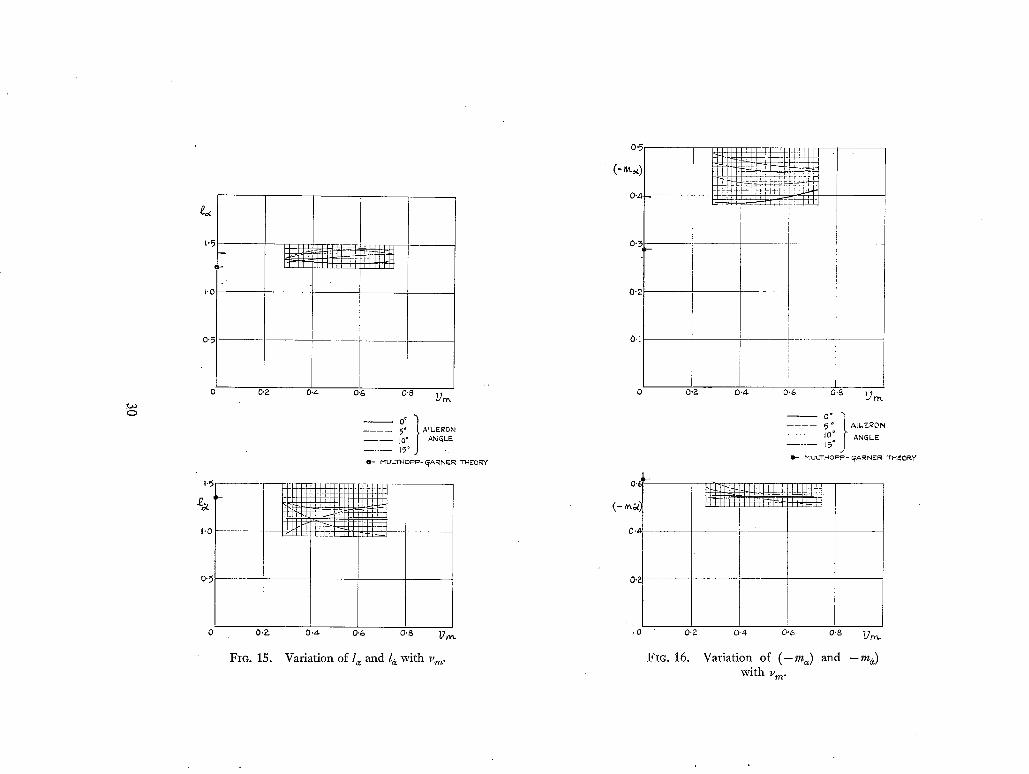
1.5
I'0
0 " 5 ~
i i i i i i
&.Ud~T, ~r-rT LU~IJ I I I l ~ l l l h l lP l l ~ lT [
F
0 0"2 0 . 4 0 ' 6
~'0
0'5
IIIIJ
0 O,?-
FIG. 15.
0-8 Z/,-,,.
o" t . . . . 5" A - - . - - ]o ° . . . . . L~ ~ ,
0 " - MULTHOF~P - ~ARNER THEORY
lllili,,,i:,,,i
0 . 4 . 0.6 " O.S U~
Variation of l= and la with v~n.
O'5
0 " ,
O ' 7 - -
0"2
0,1
0'~
0.4
0'2
.0
0"?-
0'2
FIG. 16.
0.4. 0.6 o.s Q m
~ °° t
. . . . ~ o ALL, E~O N
- - ' - - 10 ° ANGLE . . . . . 15 °
Q - MULT~4OPP- ~A~NER THEORY
L L L Z A I I , ~1 !
0.4 0.6 o.8 ?..Tr,.L
Variation of ( - m~) and - ma) with v m.

I '0
I
e~ ,--
O . ~
0.6
0 .4
0.2
O'3
0 '2
O'
1 ' ~ - J ' ,~ I ] : b l l ~J.:!'_L, !'!~ J~.HI H+I-
r -iiiJ-[ Fli i:,ili ii i-ll :t-
]
i ! I
-T-, ~°"7"° I (~ = 4 . 3 0 o TRANS~"flON WIRE. FITTED i
- - a - - I~= 8 -65 ° } + ~3 = 4-240 WiNG BARE !
0- P1ULTNQPP- ~AI~NE.R THEORY
/
0.2 0"4 0"6 0 '8 I-0 ~
1
0 - 2 -
k •
0 . 4 0 . g o.B t.O k)rrL
FIG. 17. Variation of 1B and l# with vm: mean aileron angle 0 °.
0"5
Oq
~ 0"2 . . . . . . . .
I
E u~ O,I m
I
. . . . . . . . t - -
~ / 3 = B.74 ° 2 X /3 4 ~0 ° ITRANSITION WIRES FITTED"
- - a - - / 3 = 8 . 6 s ° ~ + 63 = 4" 24 ° ) WING BARE
O- MULTHOF~F ~ l ~ARNEIR "THEORY
. . . . . . ! i [ - - - - /
i i 1 I
0 . ~ 0 -~ 0 .6 0 .8 I-.0 ~
Oq ~,
La o
O'lC
I
E
o -~- o.0
I
4
i
I
I 0 ,'::' 0.4- 0 . 6 0 ,8 I'O ' ~
Fzc 18. Variation of - ( 0 " 5 1 1 5 m ~ - 0 - 1 6 7 4 / ) and - ( 0 . 4 0 8 8 m ~ - 0 - 1 0 2 7 l ~ ) with vm: B
mean aileron angle 0 °.
0'00~
0.0t58 O'OIZ
bO
0.01 (3
0-00
0.00~
0'00,4 , - -
0.4 0.6 0.8 FO 3}to.
I r l l l l l ~ ' i ' ' 1 ' ' 1 ' ' ' ' !
l l l l ~ E 3 1 1 ' l l , ' l l l , i l i l ~[ ~llll
r P !!! l [hi: ~;!~t / ~ l l i l l I I ~ 1 1 1 ~ 1
/3= 8 ' " 'o~TRANSmON?4°3 W~RE5 v r r w E o x /3 =4.350 )
- - - e - - / 3 = 8 . 6 g ° ~ • /3 = 4 " 2 4 ° 1 WING {~A~E-
O- MULTHOPP- ~A}RNER THEORY
O.Z. o - 4 0.6 0.8 I-0 -L2r,~.
0"8
0 O-Z
@-
O'OIS - - - - - -
O'OIO
0 " 0 0 5
O.~-
FIG. 19.
i E~E
I !
i
. . . . . ~ - I l l l II-H4 , , , , ~ i I I I 1 : EI-N
0-4- 0.(~ 0"8 k 0 "l)~e,.
Variation of I~ a and ( - h a ) with v m: mean aileron angle 0 °.
0 '~
0'1
0.~.
FIG. 20.
F r
I t ! r
0 . 4 0"6 0 .8 I-O
Variation of lp and 1~ with v~: mean aileron angle 5 ° .
V~

0-5
0 . 4
o '3
' • 0"~
6
E m 0"1 m
,5, I
r ~ N
o O'IQ o
I
o o.o~
I
i . . . . .
0 . ~
- - - 3 - - /3 8 .,4-2° l TRAN51TION ~VIR55 FITTED x /5 4. b0 ° }
! I I
0 ' 4 0 ' 6 0 "8 I 'O ~D;~.
0.2_ o-,* C>C~ 0.~ I -o " ~ r . -
FIa. 21. Variation of - ( 0 - 5 1 1 5 m ~ - 0 . 1 6 7 4 1 p ) and - (0-4088m/~- 0.1027/~) with Vra :
mean aileron angle 5 ° .
0"010
~0
0.00~
0.00
0"00,
0002
0.015
O.OIC
0 . 0 0 5
I I I _LJJ. I L
0.,p
f~ = 4. 30 ° } TRANSITION WIRE F ITTED.
i
I
i I I 0'4 0-6 0-8 1.0 ~ "I ]ro "
I i I I I l l
Itr;191 I~till~';l'll";l:l.kl,, I I l ' I t l l I , , , ltJL,I
o.~: o.4. o.6 0"8 PO "I) ,.,,~
FIG. 22. Variat ion o f h d and (-h/~) wi th v m: m e a n aileron angle 5 ° .

C,O
I*O
0'~
0'~
0"~
0'2-
0"~
0"~
0"l
Lil l l l l i
11111 l l ' ~ I~ I~ ' I '~J I i
----o-- ~= f l . 42 ~ } ~ = 41 ~ 0 ~ TRAN.SLTI0N W'[RES FITTED
O,E. 0-4- 0 . 6 0.~, bO ~)r~.
0"2-
iil
El l
l;ill
FIG. 23. Va r i a t i on of lfl a n d l~ w i th Vm: m e a n a i l e ron ang le 10 °.
O'5
0-,~-
0 ' 3
N o.a
1
E ----- 0'1
I
-] I
o O, 8.42~ x ~ - 4 - 5 0 ° 1 TRP~NSLTLON WIRES FITTED
i i o.a o.4 0-6 0.8 I.o ~n-~
0-15
o 0;10 o
E
0'2
. . . . . . . . . ,,LI I ' ' IIIII"',,, 1111111 .......... MH
0"~ O'~ 0"8 l '0 v ~
FIG. 24. Variation of - ( 0 - 5 1 1 5 m d - 0 " 1 6 7 4 / p ) and - ( 0 . 4 0 8 8 m ~ - 0 .1027/~) w i t h v m:
m e a n aileron angle 10 ° .
0.00: . . . . . . . . 7[- . . . . . .
/ O.OOI
0.004
0-002
. . . . . . . . . . . . . . . . . . t2o\L S . . . . . . . . .
X /3-4"50°~ TRANSITION WIRES FITTED . . . . . . - . . . . ]
/ 0'~ 0-4 O-G O'B l-O
. . . . . . . 7 . . . . . . . . .
I
~9~.
C-K~}
O'OI5 - -
O-OlO
0"005
' ~ T I I
0"?.
FIC. 25.
iiiii:iii
0-~ 0 .6 0 .8 I.O -p,,,
Variation of h# and ( -h#) with v m:
mean aileron angle 10 °.
0'~
(-,~)
0"~
( -~ )
0'1
0 . 2
÷ ~ @-i-I-P~PP-I--H-I H
0 0.~
Fm. 26.
0.4 . 0-6 0-8 Po ])m.
~t. 50 ° FITTED
--z--- 13 = B'B5 ° + (3 4" 24* ~ WING BARE.
0- I~ULTHOPP- ~ARN~R THEORY
0.4 O.G O.B t.O "Dot
Variation of ( -m#) and (--m#) with v m: mean aileron angle 0 °,

GO
0"6
( - " ,~)
0.4
0.~
0-:5
(- ~/~)
0"Z
0.[
0.2
q l l i i i i ~ I1~11 ~ibi li in ~,
0 - 4 o -6 o.8 t.o q]r~.
- - ' - ~ (3= 8"426 t TRAN~ITION WII~F..S " (3= 4"50 ° FITTED
L-}-[ .... IJ ...... ,., ....... ,~ ,~- ~, ,~-~I I I I I I 1 .4444- ,- ...... 1 IIII II ill IPl II~
0 0 . ~ 0"4 0 , 6 0-5
Fig. 27.
, , " l l i l l ' " l l r l l , , , JLLLLIII'"IIII',,, H_q4q=rq:t,+4~-~
I
I L I '0
Variation of ( - m ~ ) and ( -m#) with v,,,: m e a n a i l e r o n a n g l e 5 ° .
( - ~
O.~
0"4
0.2
o ' 3
(-,,,,~)
0-'2
0.1
0 0-2.
Fro. 28.
~ , , 7, ,'~'" r", Iii ' 11ii
I
0 '~ 0 .4 0'G 0"6
I!/bl
~= 8.42°~ TRAN~ITION WIRK$
]~ = 4.30 ° ) ~'ITTF-..D
i01 i"LI , . . . . . • ' I . . . . . I I I I I L
o-~. o,6 o-S i.o -l)r~_
Variation of ( -rap) and ( -m~) with v~: mean aileron angle 10 ° .

....1
0,~
0,,I
O'P- o 4 O,G
0 '2
- 0 ~
- 0 4
Fio. 29.
f
02 /
/
.i- /
/ /
/ /
/ /
/ /
/ /
I ,o ",~-m.
MEASURED: M E A N A I L E R O N A N G L E O ~
i .... T H E O R Y 3 - D FORCES i Q N I N B O A R D W I N C T
THEC3RY ~_-I:~ F O R C E S O N I N B O A R D W I N ~ ,
I - MULTHOPP- ~ A R N E R THEORY
I I
Comparison of calculated and measured values for ld and l B.
0 ' 6
1
0 " 4
0 ' ~
0 3
0'~-
t
O,I
O R 0 ' 4 0 ' 6 0 -~ I O @m.
- - M E A S U R E D : M E A N A I L E R O N ANCTLE 0 °
. . . . . T H E O R Y 3 -D FORCE5 O N I N B O A R D W I N ~ ,
. . . . . "THEORY ~-D FORCES O N I N B O A R D W I N ~
M U L T H O P P - CTARNER T H E O R Y
f / /
/ /
/ /
/ /
/ /
/
0"~- 0 " 4
Fro . 30.
~_ "I~
Comparison of calculated and measured values for (-rap) and (-roB).

k./3
o o 12
0 . 0 o 8
0 0 0 4
0';: ' 0'~- O'G 0 ' 8 hO ~ . ~
0 . 0 ~ 0
o . o 1 0
- - M E A S U R E E ) : M E A N AtL.EROiM A N I ~ L E 0 ~
T R A N S I T I O N W I R E S F I T T E E ) "
. . . . . . T H E O R y • P-- b FORCES O N I N N E R W I N E T
. . . . . . . T H E O R Y : F A C T O R E D P--E) F O R C E S O N
INNER WIIM~
0"- M U L T H O P F ~ - ~ A R N E F ~ T H E O R Y
0 - 2 0.4- 0 . 6 O,P- 1.0 "b~-.m.
FIC. 31. Comparison of calculated and measured values for h# and (-h#).
(86213) Wt . 64/1857 K.5 2/63 I-Iw.
38
Publications of the Aeronautical Research Council
ANNUAL TECHNICAL REPORTS OF THE AERONAUTICAL RESEARCH COUNCIL (BOUND VOLUMES)
*942 Vol. I. Aero and Hydrodynamics, Aerofoils, Airscrews, Engines. 75s. (post 2s. 9d.) Vol. II. Noise, Parachutes, Stability and Control, Structures, Vibration, Wind Tunnels. 47s. 6d. (post 2s. 3d.)
I943 Vol. I. Aerodynamics, Aerofoils, Airscrews. 8os. (post 2s. 6d.) Vol. II. Engines, Flutter, Materials, Parachutes, Performance, Stability and Control, Structures.
9os. (post 2s. 9d.) 1944 Vol. i. Aero and Hydrodynamics, Aerofoils, Aircraft, Airscrews, Controls. 843. (post 3s.)
Vol. II. Flutter and Vibration, Materials, Miscellaneous, Navigation, Parachutes, Performance, Plates and Panels, Stability, Structures, Test Equipment, Wind Tunnels. 843. (post 3s.)
I945 Vol. I. Aero and Hydrodynamics, Aerofoils. I3OS. (post 3s. 6d.) Vol. II. Aircraft, Airscrews, Controls. x3os. (post 3s. 6d.) Vol. III. Flutter and Vibration, Instruments, Miscellaneous, Parachutes, Plates and Panels, Propulsion.
x30s. (post 3s. 3d.) Vol. IV. Stability, Structures, Wind Tunnels, Wind Tunnel Technique.*: 130s. (post 3s. 3d.)
1946 Vol. I. Accidents, Aerodyna~fies, Aerofoils and Hydrofoils. z68s. (post 3s. 9d.) Vol. II. Airscrews, Cabin Cooling, Chemical Hazards, Controls, Flames, Flutter, Helicopters, Instruments and
Instrumentation, Interference, Jets, Miscellaneous, Parachutes. i68s. (post 3s. 3d.) Vol. III. Performance, Propulsion, Seaplanes, Stability, Structures, Wind Tunnels. x68s. (post 3s. 6d.)
1947 Vol. I. Aerodynamics, Aerofoils, Aircraft. I68S. (post 3s. 9d.) Vol. II. Airscrews and Rotors, Controls, Flutter, Materials, 1Vfiscellaneous, Parachutes, Propulsion, Seaplanes,
Stability, Structures, Take-off and Landing. i68s. (post 3s. 9d.)
1948 Vol. I. Aerodynamics, Aerofoils, Aircraft, Airscrews, Controls, Flutter and Vibration, Helicopters, Instruments, Propulsion, Seaplane, Stability, Structures, Wind Tunnels. 13os. (post 3s. 3d.)
Vol. II. Aerodynamics, Aerofoils, Aircraft, Airscrews, Controls, Flutter and Vibration, Helicopters, Instruments, Propulsion, Seaplane, Stability, Structures, Wind Tunnels. I lOS. (post 3s. 3d.)
Special Volumes Vol. I. Aero and Hydrodynamics, Aerofoils, Controls, Flutter, Kites, Parachutes, Performance, Propulsion,
Stability. i26s. (post 3s.) Vol. II. Aero and Hydrodynamics, Aerofoils, Airscrews, Controls, Flutter, Materials, Miscellaneous, Parachutes,
Propulsion, Stability, Structures. I47S. (post 3s.) Vol. III. Aero and Hydrodynamics, Aerofoils, Airscrews, Controls, Flutter, Kites, Miscellaneous, Parachutes,
Propulsion, Seaplanes, Stability, Structures, Test Equipment. 189s. (post 3s. 9d.)
Reviews of the Aeronautical Research Council 1939-48 3s. (post 6d.) I949-54 5s. (post 5d-)
Index to all Reports and Memoranda published in the Annual Technical Reports 19o9-1947 R. & M. 2600 (out of print)
Indexes to the Reports and Memoranda of the Aeronautical Research Council Between Nos. 2351-2449 R. & M. No. 245o 2s. (post 3d.) Between Nos. 2451-2549 Between Nos. 2551-2649 Between Nos. 2651-2749 Between Nos. 2751-2849 Between Nos. 2851-2949 Between Nos. 295 x-3o49 Between Nos. 3o5 I-3149
R. & M. No. 2550 2s. 6d. (post 3d.) R. & M. No. 2650 2s. 6d. (post 3d.) R. & M. No. 275o 2s. 6d. (post 3d.) R. & M. No. 285o 2s. 6d. (post 3d.) R. & M. No. 2950 3s. (post 3d.) R. & M. No. 3o5o 3s. 6d. (post 3d.) R. & M. No. 315o 3s. 6d. (post 3d.)
HER MAJESTY'S STATIONERY OFFICE f rom the addresses overleaf

-i
R. & Mo No. 3307
© Crown copyright 1963
Printed and published by HER ~/~AJESTY'S STATIONERY OFFICE
To be pro-chased from York House, Kingsway, London w.c.z
423 Oxford Street, London w.I IBA Castle Street, Edinburgh 2
Io9 St. Mary Street, Cardiff 39 King Street, Manchester 2
50 Fairfax Street, Bristol i 35 Smallbrook, Ringway, Birmingham 5
8o Chichester Street, Belfast I or through any bookseller
Printed in England
~o & Mo NOo 3307
S.O. Code No. z3-33o7