aes standard for audio applications of networks - high … · 2018-02-14 · aes67-xxxx revision of...
TRANSCRIPT

AES STANDARDS: DRAFT FOR COMMENT ONLY
DRAFT REVISED AES67-xxxx
AES STANDARDS: DRAFT FOR COMMENT ONLY
STANDARDS AND
INFORMATION DOCUMENTS
Call for comment on DRAFT REVISED AES standard for
audio applications of networks - High-performance streaming audio-over-IP interoperability
This document was developed by a writing group of the Audio Engineering Society Standards Committee (AESSC) and has been prepared for comment according to AES policies and procedures. It has been brought to the attention of International Electrotechnical Commission Technical Committee 100. Existing international standards relating to the subject of this document were used and referenced throughout its development. Address comments by E-mail to [email protected], or by mail to the AESSC Secretariat, Audio Engineering Society, PO Box 731, Lake Oswego OR 97034. Only comments so addressed will be considered. E-mail is preferred. Comments that suggest changes must include proposed wording. Comments shall be restricted to this document only. Send comments to other documents separately. Recipients of this document are invited to submit, with their comments, notification of any relevant patent rights of which they are aware and to provide supporting documentation. This document will be approved by the AES after any adverse comment received within six weeks of the publication of this call on http://www.aes.org/standards/comments/, 2018-02-14 has been resolved. Any person receiving this call first through the JAES distribution may inform the Secretariat immediately of an intention to comment within a month of this distribution. Because this document is a draft and is subject to change, no portion of it shall be quoted in any publication without the written permission of the AES, and all published references to it must include a prominent warning that the draft will be changed and must not be used as a standard.

The AES Standards Committee is the organization responsible for the standards program of the Audio Engineering Society. It publishes technical standards, information documents and technical reports. Working groups and task groups with a fully international membership are engaged in writing standards covering fields that include topics of specific relevance to professional audio. Membership of any AES standards working group is open to all individuals who are materially and directly affected by the documents that may be issued under the scope of that working group.
Complete information, including working group scopes and project status is available at http://www.aes.org/standards. Enquiries may be addressed to [email protected]
The AES Standards Committee is supported in part by those listed below who, as Standards Sustainers, make significant financial contribution to its operation.
This list is current as of 2017/7/25
STANDARDS

AES67-xxxx Revision of AES67-2015
aes67-r-171107-draft-rev-cfc-rc4.doc
Page 1 of 70
AES STANDARDS: DRAFT FOR COMMENT ONLY
DRAFT REVISED AES standard for
audio applications of networks - High-performance streaming audio-over-IP interoperability
Published by Audio Engineering Society, Inc. Copyright ©2013, 2015, 2017, 2018 by the Audio Engineering Society
Abstract
High-performance media networks support professional quality audio (16 bit, 44,1 kHz and higher) with low latencies (less than 10 milliseconds) compatible with live sound reinforcement. The level of network performance required to meet these requirements is available on local-area networks and is achievable on enterprise-scale networks. A number of networked audio systems have been developed to support high-performance media networking but until now there were no recommendations for operating these systems in an interoperable manner. This standard provides comprehensive interoperability recommendations in the areas of synchronization, media clock identification, network transport, encoding and streaming, session description and connection management.
An AES standard implies a consensus of those directly and materially affected by its scope and provisions and is intended as a guide to aid the manufacturer, the consumer, and the general public. The existence of an AES standard does not in any respect preclude anyone, whether or not he or she has approved the document, from manufacturing, marketing, purchasing, or using products, processes, or procedures not in agreement with the standard. Prior to approval, all parties were provided opportunities to comment or object to any provision. Attention is drawn to the possibility that some of the elements of this AES standard or information document may be the subject of patent rights. AES shall not be held responsible for identifying any or all such patents. Approval does not assume any liability to any patent owner, nor does it assume any obligation whatever to parties adopting the standards document. This document is subject to periodic review and users are cautioned to obtain the latest edition. Recipients of this document are invited to submit, with their comments, notification of any relevant patent rights of which they are aware and to provide supporting documentation.
Audio Engineering Society Inc. 551 Fifth Avenue, New York, NY 10176, US. www.aes.org/standards [email protected]

AES STANDARDS: DRAFT FOR COMMENT ONLY
aes67-r-171107-draft-rev-cfc-rc4.doc
Page 2 of 70
AES STANDARDS: DRAFT FOR COMMENT ONLY
Contents
0 Introduction..........................................................................................................................................6 0.1 General............................................................................................................................................6 0.2 Patents.............................................................................................................................................6
1 Scope ....................................................................................................................................................7 2 Normative references ............................................................................................................................7 3 Definitions and abbreviations................................................................................................................8 4 Synchronization ..................................................................................................................................13
4.0 General..........................................................................................................................................13 4.1 IP network synchronization .............................................................................................................13 4.2 IEEE 1588 network synchronization ................................................................................................13 4.3 AVB network synchronization.........................................................................................................13
5 Media clocks .......................................................................................................................................13 6 Transport ...........................................................................................................................................14
6.0 General..........................................................................................................................................14 6.1 Network layer ................................................................................................................................14 6.2 Quality of service ...........................................................................................................................15 6.3 Transport layer...............................................................................................................................16
7 Encoding and streaming .....................................................................................................................17 7.0 Introduction ...................................................................................................................................17 7.1 Payload format and sampling rate ....................................................................................................17 7.2 Packet time ....................................................................................................................................17
7.2.0 General ...................................................................................................................................17 7.2.1 Required packet time................................................................................................................18 7.2.2 Recommended packet times......................................................................................................18
7.3 Stream channel count......................................................................................................................19 7.4 Link offset .....................................................................................................................................19 7.5 Sender timing and receiver buffering ...............................................................................................20 7.6 Multicasting...................................................................................................................................21
8 Session description..............................................................................................................................21 8.0 General..........................................................................................................................................21 8.1 Packet time ....................................................................................................................................21 8.2 Clock source ..................................................................................................................................22 8.3 RTP and media clock......................................................................................................................23 8.4 Payload types.................................................................................................................................23 8.5 Example descriptions......................................................................................................................23
8.5.0 Errata......................................................................................................................................23 8.5.1 Multicast session description example .......................................................................................23 8.5.2 Unicast session description example ..........................................................................................24
9 Discovery ............................................................................................................................................24 10 Connection management ...................................................................................................................24
10.0 General........................................................................................................................................24 10.1 Unicast connections ......................................................................................................................24
10.1.1 SIP URI ................................................................................................................................24 10.1.2 Server and serverless modes....................................................................................................25 10.1.3 User-Agent ............................................................................................................................25 10.1.4 Format negotiation .................................................................................................................25 10.1.5 Packet time negotiation...........................................................................................................25
10.2 Multicast connections ...................................................................................................................25

AES STANDARDS: DRAFT FOR COMMENT ONLY
aes67-r-171107-draft-rev-cfc-rc4.doc
Page 3 of 70
AES STANDARDS: DRAFT FOR COMMENT ONLY
Annex A (Normative) - Media profile.....................................................................................................26 A.0 General.........................................................................................................................................26 A.1 Media profile description ...............................................................................................................26 A.2 Media profile ................................................................................................................................26
A.2.1 Identification ..........................................................................................................................26 A.2.2 PTP attribute values ................................................................................................................26 A.2.3 PTP options ............................................................................................................................28 A.2.4 Clock physical requirements ....................................................................................................29
Annex B (Informative) - Network QoS configuration recommendations ................................................30 B.0 General .........................................................................................................................................30 B.1 DiffServ network configuration.......................................................................................................30
B.1.1 Clock .....................................................................................................................................30 B.1.2 Media.....................................................................................................................................31 B.1.3 Best effort...............................................................................................................................31
Annex C (Informative) – AVB network transport ..................................................................................33 C.0 General .........................................................................................................................................33 C.1 AVB network transport ..................................................................................................................33
C.1.1 Interoperable media as AVB time-sensitive streams ...................................................................33 C.1.2 Interoperable media as other traffic ...........................................................................................34
Annex D (Informative) - Interfacing to IEEE 802.1AS clock domains ....................................................36 D.0 General.........................................................................................................................................36 D.1 Boundary clock interface................................................................................................................36 D.2 Ordinary clock interface.................................................................................................................36 D.3 Traceable reference........................................................................................................................36 D.4 AVB network as a boundary clock ..................................................................................................37
Annex E (Informative) – Discovery systems ...........................................................................................38 E.0 General .........................................................................................................................................38 E.1 Bonjour.........................................................................................................................................38 E.2 SAP ..............................................................................................................................................38 E.3 Axia Discovery Protocol.................................................................................................................38 E.4 Wheatstone WheatnetIP Discovery Protocol.....................................................................................38 E.5 AMWA NMOS Discovery and Registration Specification (IS-04) .....................................................39
Annex F (Informative) - Glossary ..........................................................................................................40 Annex G (Normative) - Protocol implementation conformance criteria..................................................42
G.1 Introduction ..................................................................................................................................42 G.2 Instructions for completing the PICS proforma ................................................................................42 G.3 PICS proforma ..............................................................................................................................43
G.3.1 Identification ..........................................................................................................................43 G.3.2 Synchronization ......................................................................................................................44 G.3.3 Media clocks .........................................................................................................................45 G.3.4 Transport................................................................................................................................46 G.3.5 Encoding and streaming...........................................................................................................49 G.3.6 Session description..................................................................................................................56 G.3.7 Clock source...........................................................................................................................58 G.3.8 Discovery ...............................................................................................................................60 G.3.9 Connection management..........................................................................................................60 G.3.10 Media profile (Normative) .....................................................................................................61 G.3.11 Media profile ........................................................................................................................61
G.4 – Qualification criteria for encoding and streaming capabilities .........................................................69 Annex H Bibliography ...........................................................................................................................70

AES STANDARDS: DRAFT FOR COMMENT ONLY
aes67-r-171107-draft-rev-cfc-rc4.doc
Page 4 of 70
AES STANDARDS: DRAFT FOR COMMENT ONLY
Foreword This foreword is not part of the AES67-2013 AES standard for audio applications of networks - High-performance streaming audio-over-IP interoperability
This document was developed in project AES-X192, in the SC-02-12-H task group on high-performance streaming audio-over-IP interoperability, under the leadership of Kevin Gross.
Members of the writing group that contributed to this document in draft are: R. Abraham, J. Amate, M. Barbour, C. Becker-Foss, J. Berryman, M. Bishop, H. Blum, J. Boqvist, T. Borland, N. Borthwick, L. Bradshaw, P. Briscoe, L. Brito, J. Britton, C. Broad, N. Brunsgaard, D. Brutzman, E. Bukont Jr., A. Calvanese, R. Camprodon, M. Carter, A. Cedronius, A. Clark, H. Clarke, M. Coinchon, P. Cyrta, S. de Jaham, P. Demuytere, J. Dibley, A. Dickens, P. Dietrich, C. Dodds, S. Dove, A. Eales, E. Echols, R. Economaki, T. Edwards, A. Elder, L. Ellison, K. Fitzke, J. Fletcher, S. Flock, R. Foss, P. Foulkes, F. Gierlinger, R. Goforth, J. Grant, M. Graubner, D. Gravereaux, S. Gray, H. Hansen, B. Harshbarger, S. Heinzmann, A. Hildebrand, D. Hoch, M. Holtmann, Os. Igumbor, H. Jahne, T. Johansson, M. J. Teener, S. Johnson, L. Jonsson, A. Karamustafaoglu, K. Kearney, P. Keller, J. Koftinoff, P. Koftinoff, D. Koss, S. Langhans, M. Lave, D. Lazecko, S. Ledergerber, C. Lefebvre, J. Lindsay, G. Linis, S. Loehberg, A. Louko, A. Makivirta, J. A. Martinez, A. Mayo, W. McQuay, C. Merienne, A. Metz, J. Meunier, J. Meyer, R. Michl, S. Millan, D. O'Gwynn, N. O'Neill, H. Okai-Tettey, K. Parker, J. Passaniti, J. Peavey, J. Perez, W. Peters, S. Price, S. Pro, M. Quaix, F. Ragenard, R. Rayburn, D. Rice, T. Rohwedder, G. Rosenboom, M. Saito, M. S. Carreres, J. Sauter, R. Schoonbroodt, V. Schueppel, P. Schwizer, S. Scott, G. Shay, T. Shuttleworth, D. Silver, J. Simpson, M. Sims, A. Smimite, J. Snow, T. Staros, P. Stevens, J. M. Strawn, N. Sturmel, M. Szlapka, T. Thompson, P. Treleaven, A. Trevena, S. Turner, R. van der Zalm, B. van Kempen, I. Vysick, J. P. Waddell, Y. Wang, P. Warrington, H. Weibel, A. Williams, M. Willsher, A. Witham, J. Wood, J. A. Yeary, J. Yoshio, P. Yurt, U. Zanghieri, D. Zimmermann, R. Zwiebel.
This document was edited by Kevin Gross.
Richard Foss Chair, working group SC-02-12, 2013-07-18
Foreword to second edition, 2015
This revision includes minor changes identified during 'plugfest' testing in October 2014 and was developed in task group SC-02-12-M. It includes updated references to RFC 7273, and clarifications in 6.3, 8.1, and 8.5.
Members of the task group that contributed to this revision in draft are: R. Abraham, J. Amate, L. Andrieu, R. Barbieri-Carrera, M. Barbour, C. Becker-Foss, F. Bergholtz, J.A. Berryman, J. Boqvist, J. Breitlow, D. Brulhart, B.J. Buchalter, A. Calvanese, C. Cellier, K. Cleary, M. Danielson, I. Dennis, C. Diehl, S. Dove, T. Duffy, J. Dunn, J. Evanson, J. Fletcher, S. Flock, R. Foss, J. Freyberger, G. Gebler, J. Grant, K. Gross, S. Heinzmann, E. Heurtel, A. Hildebrand, F. Hoyer, T. Johansson, L. Jonsson, B. Klinkradt, J. Koftinoff, S. Langhans, S. Ledergerber, C. Lefebvre, S. Leschka, Jo. Lindsay, G. Linis, A. Lucas, A. Makivirta, A. Metz, J. Meyer, R. Michl, G. Passador, J. Peavey, M. Quaix, C.R. Reed, T. Rohwedder, M. Schuchert, V. Schueppel, G. Shay, P. Stevens, N. Sturmel, M. Szlapka, P. Treleaven, A. van den Broek, B. van Kempen, J.P. Waddell, A. Williams, K. Wu, N. Yamaguchi, R. Zwiebel.
The task group was led by Kevin Gross.
Richard Foss Chair, working group SC-02-12, 2015-07-27

AES STANDARDS: DRAFT FOR COMMENT ONLY
aes67-r-171107-draft-rev-cfc-rc4.doc
Page 5 of 70
AES STANDARDS: DRAFT FOR COMMENT ONLY
Foreword to third edition, 2017
This revision contains clarifications and minor corrections and adds a Protocol Implementation Conformance Statement (PICS) as Annex G. A new sender keep-alive recommendation, has been added to clause 6.3. Minor clarifications and corrections include a specification of MTU requirements in the presence of allowed (but not recommended) additional information in the RTP header and correcting SDP examples in clause 8.5 to match an erratum issued by the IETF on RFC 7273. These revisions were developed in task group SC-02-12-M.
Members of the task group that contributed to this revision in draft are: R. Abraham, J. Amate, N. Amaya, L. Andrieu, R. Barbieri-Carrera, M. Barbour, C. Becker-Foss, R. Bell, F. Bergholtz, J. A. Berryman, M. Blackburn, A. Boenninghoff, J. Boqvist, L. Bradshaw, D. Breithaupt, J. Breitlow, D. Brulhart, B. J. Buchalter, R. Bugg, R. Cabot, A. Caceres, A. Calvanese, C. Cellier, R. Charlesworth, K. Cleary, B. Cochran, A. Cooper, M. Danielson, T. deBrouwer, I. Dennis, C. Diehl, G. Diehl, S. Dove, T. Duffy, J. Dunn, J. Evanson, J. Fletcher, S. Flock, R. Foss, J. Freyberger, G. Gauthier, G. Gebler, J. Grant, E. Grossman, S. Heinzmann, M. Henke, M. Henry, E. Heurtel, A. Hildebrand, T. Holton, A. Holzinger, F. Hoyer, L. Huapaya, H. Jesuiter, T. Johansson, L. Jonsson, N. Keroe, A. Kitagawa, B. Klinkradt, J. Koftinoff, S. Langhans, J. Laundon, S. Ledergerber, C. Lefebvre, S. Leschka, E. Lestage, J. Lindsay, G. Linis, K. Lyver, A. Makivirta, C. Mannett, S. Mertens, A. Metz, J. Meyer, R. Michl, E. Miehs, T. Neuhaus, C. Nighman, N. Nzoyem, B. Olson, M. Overton, O. Palm, K. Parker, G. Passador, J. Peavey, J. Pruitt, M. Quaix, C. R. Reed, T. Rohwedder, A. Santos, G. Scherling, M. Schettke, M. Schuchert, V. Schueppel, S. Scott, A. Sharifan, G. Shay, M. Smaak, K. Soma, P. Stevens, N. Sturmel, M. Szlapka, J. Tikkanen, P. Treleaven, A. van den Broek, B. van Kempen, S. van Tienen, J. P. Waddell, P. Walker, D. Walters, C. Ware, P. Warrington, E. Wetzell, L. Whitcomb, A. Williams, K. Wu, N. Yamaguchi, M. Yonge, R. Zwiebel.
The task group was led by Kevin Gross.
The PICS (annex H) was edited by Gints Linis
Morten Lave Chair, working group SC-02-12, 2017-12-11
Note on normative language
In AES standards documents, sentences containing the word “shall” are requirements for compliance with the document. Sentences containing the verb “should” are strong suggestions (recommendations). Sentences giving permission use the verb “may”. Sentences expressing a possibility use the verb “can”.
AES STANDARDS: DRAFT FOR COMMENT ONLY
aes67-r-171107-draft-rev-cfc-rc4.doc
Page 6 of 70
AES STANDARDS: DRAFT FOR COMMENT ONLY
DRAFT REVISED AES standard for
audio applications of networks - High-performance streaming audio-over-IP interoperability
0 Introduction
0.1 General High-performance media networks support professional quality audio (16 bit, 44,1 kHz and higher) with low latencies (less than 10 ms) compatible with live sound reinforcement. The level of network performance required to meet these requirements is available on local-area networks and is achievable on enterprise-scale networks but is generally not available on wide-area networks or the public internet.
The most recent generation of these media networks use a diversity of proprietary and standard protocols. Despite a common basis in Internet Protocol, the systems do not interoperate.
This standard provides specific recommendations for interoperability. The standard focuses on defining how existing protocols are used to create an interoperable system. No new protocols have been developed to achieve this.
The standard is expected to be useful for commercial audio applications including fixed and touring live sound reinforcement. It is also expected to be useful for distribution within broadcast, music production and post-production facilities.
This standard depends on established network protocols (see clause 2). These protocols may include additional options that are not required by this standard. Implementations of AES67 should tolerate these additional options.
0.2 Patents The Audio Engineering Society draws attention to the fact that it is claimed that compliance with this AES standard or information document may involve the use of a patent.
The AES holds no position concerning the evidence, validity and scope of this patent right.
The holder of this patent right has assured the AES that it is willing to negotiate licenses under reasonable and non-discriminatory terms and conditions with applicants throughout the world. In this respect, the statement of the holder of this patent right is archived with the AES and listed on the public AES web site.
Information may be obtained from.
Audinate Pty Ltd. PO Box 855 Ultimo, NSW 2007 Australia
Attention is drawn to the possibility that some of the elements of this AES standard or information document may be the subject of patent rights other than those identified above. AES shall not be held responsible for identifying any or all such patent rights.

AES STANDARDS: DRAFT FOR COMMENT ONLY
aes67-r-171107-draft-rev-cfc-rc4.doc
Page 7 of 70
AES STANDARDS: DRAFT FOR COMMENT ONLY
1 Scope This standard defines an interoperability mode for transport of high-performance audio over networks based on the Internet Protocol. For the purposes of the standard, high-performance audio refers to audio with full bandwidth and low noise. These requirements imply linear PCM coding with a sampling frequency of 44,1 kHz and higher and resolution of 16 bits and higher. High performance also implies a low-latency capability compatible with live sound applications. The standard considers latency performance of 10 milliseconds or less.
2 Normative references The following referenced documents are indispensable for the application of this document. For dated references, only the edition cited applies. For undated references, the latest edition of the referenced document (including any amendments) applies.
AES11 - AES recommended practice for digital audio engineering - Synchronization of digital audio equipment in studio operations; Audio Engineering Society, New York, NY., US.
IEEE 1588-2008 - IEEE Standard for a Precision Clock Synchronization Protocol for Networked Measurement and Control Systems, July 2008, Institute of Electrical and Electronics Engineers (IEEE), US.
RFC 768 – User Datagram Protocol”, Internet Engineering Task Force
RFC 791 – Internet Protocol, Internet Engineering Task Force
RFC 1112 – Host Extensions for IP Multicasting, Internet Engineering Task Force
RFC 2236 - Internet Group Management Protocol, Version 2, Internet Engineering Task Force
RFC 2474 – Definition of the Differentiated Services Field (DS Field) in the IPv4 and IPv6 Headers, Internet Engineering Task Force
RFC 2616 - Hypertext Transfer Protocol - HTTP/1.1, Internet Engineering Task Force
RFC 2974 – Session Announcement Protocol, Internet Engineering Task Force
RFC 3190 – RTP Payload Format for 12-bit DAT Audio and 20- and 24-bit Linear Sampled Audio, Internet Engineering Task Force
RFC 3261 - SIP: Session Initiation Protocol, Internet Engineering Task Force
RFC 3264 - An Offer/Answer Model with the Session Description Protocol (SDP), Internet Engineering Task Force
RFC 3376 - Internet Group Management Protocol, Version 3, Internet Engineering Task Force
RFC 3550 – RTP: A Transport Protocol for Real-Time Applications, Internet Engineering Task Force
RFC 3551 - RTP Profile for Audio and Video Conferences with Minimal Control, Internet Engineering Task Force
RFC 4566 – Session Description Protocol, Internet Engineering Task Force
RFC 5939 – Session Description Protocol (SDP) Capability Negotiation, Internet Engineering Task Force
RFC 7273 – RTP Clock Source Signalling, Internet Engineering Task Force

AES STANDARDS: DRAFT FOR COMMENT ONLY
aes67-r-171107-draft-rev-cfc-rc4.doc
Page 8 of 70
AES STANDARDS: DRAFT FOR COMMENT ONLY
3 Definitions and abbreviations For the purposes of this document, the following terms, definitions, and abbreviations apply.
3.1 Audio stream See RTP stream.
3.2 Audio Video Bridging AVB describes enhanced Ethernet networks specified in IEEE 802.1BA, IEEE 802.1Q-2011 and IEEE 802.1AS.
3.3 Boundary Clock A clock that has multiple Precision Time Protocol (PTP) ports in a domain and maintains the timescale used in the domain. It may serve as the source of time, that is, be a master clock; and may synchronize to another clock, that is, be a slave clock. See IEEE 1588-2008.
3.4 Byte A unit comprising 8 bits of data. Over IP networks, data is transported in units of bytes.
3.5 Digital Audio Reference Signal DARS an audio clock signal defined in AES11.
3.6 CSRC The contributing source (CSRC) is the source of a stream of RTP packets that has contributed to the combined stream produced by an RTP mixer
3.7 DiffServ Differentiated services (DiffServ) is a system for classifying traffic and providing quality of service (QoS) on an IP network.
3.8 DSCP The differentiated services code point (DSCP) is a 6-bit field in the IP packet header that is used for classification purposes. DSCP is part of the differentiated services architecture.
3.9 End-to-end Transparent Clock A transparent clock that supports the use of the end-to-end delay measurement mechanism between slave clocks and the master clock. See IEEE 1588-2008.
3.10 Ethernet Ethernet is a physical and data link layer family of computer networking technologies for local area networks (LANs). Ethernet uses a bus or star topology and supports data transfer rates from 10 Mbps, through 100 Mbps (Fast Ethernet) and onto Gigabit Ethernet, supporting data rates of 1 gigabit (1,000 megabits) per second.
3.11 EUI-64 A 64-bit globally unique identifier formed by combining a registered 24 or 36-bit company identifier and a company unique device identifier. The EUI-64 is similar to the EUI-48 which is used to assign Ethernet media access control (MAC) addresses.

AES STANDARDS: DRAFT FOR COMMENT ONLY
aes67-r-171107-draft-rev-cfc-rc4.doc
Page 9 of 70
AES STANDARDS: DRAFT FOR COMMENT ONLY
3.12 Grandmaster identifier GMID an EUI-64 used in IEEE 1588 and IEEE 802.1AS synchronization standards to uniquely identify the grandmaster serving a synchronization domain.
3.13 Grandmaster The master source of synchronization for clock distribution via PTP. The grandmaster is a network device and is identified by an EUI-64.
3.14 IEEE Institute of Electrical and Electronics Engineers is a professional association dedicated to advancing technological innovation and excellence. The IEEE publishes a wide range of communications standards.
3.15 IETF Internet Engineering Task Force is the volunteer standards-developing organization responsible for the Internet Protocol suite.
3.16 IGMP Internet Group Management Protocol (IGMP) is a communications protocol used by hosts to report their multicast group memberships to IPv4 routers.
3.17 Internet Protocol IP the network layer protocol commonly used to transport data on networks built through interconnection of one or more local-area networks.
3.18 IPv4 Internet Protocol version 4 is the most widely deployed version of the protocol and is widely used on the Internet and on local area networks (LANs).
3.19 IPv6 Internet Protocol version 6 is the most recent revision of the Internet Protocol and is intended to replace IPv4 eventually.
3.20 Link offset Link offset specifies the amount of time media spends on the network and in buffers at the sender and receiver as illustrated in figure 1. Link offset is also known as network latency or playout delay.
3.21 Media clock The clock used by senders to sample and receivers to play digital media streams. The media clock for audio streams reads in units of samples. The relationship between media clock and network clock is defined in 5.
3.22 Media packet One of the data packets carrying media data as part of a media stream. A media packet contains one or more samples for one or more audio channels.

AES STANDARDS: DRAFT FOR COMMENT ONLY
aes67-r-171107-draft-rev-cfc-rc4.doc
Page 10 of 70
AES STANDARDS: DRAFT FOR COMMENT ONLY
3.23 Media stream See RTP stream.
3.24 Maximum transmission unit MTU The size of the IP packet, measured in bytes, that can be transferred using a specific data link connection. The MTU for an Ethernet data link is 1500 bytes.
3.25 Network clock The time delivered by the network synchronization mechanism defined in 4. The network clock reads in units of seconds.
3.26 Network layer The network layer is layer 3 of the OSI model and is responsible for packet forwarding and routing of variable-length data sequences from a source to a destination.
3.27 OSI model The Open Systems Interconnect Model characterizes and standardizes the functions of a communications system in terms of abstraction layers.
3.28 Packet time The real-time duration of the media data contained in a media packet. For example, a packet containing 12 samples of 48 kHz audio has a packet time of 12 ÷ 48 kHz = 250 microseconds.
3.29 Peer-to-peer Transparent Clock A transparent clock that, in addition to providing Precision Time Protocol (PTP) event transit time information, also provides corrections for the propagation delay of the link connected to the port receiving the PTP event message. In the presence of peer-to-peer transparent clocks, delay measurements between slave clocks and the master clock are performed using the peer-to-peer delay measurement mechanism. Source: IEEE 1588-2008.
3.30 Precision time protocol PTP The general class clock distribution protocol standardized in IEEE 1588-2002, IEEE 1588-2008 and IEEE 802.1AS-2011.
3.31 Quality of service QoS describes a system for classifying, marking and delivering traffic across a network in accordance with its performance requirements.
3.32 Receiver A network device with ability to receive at least one media stream from the network.
3.33 Request for Comment RFC Request for Comments are memorandums published by the IETF relevant for the working of the Internet and Internet-connected systems. RFCs are referenced by number. RFC 791, for example, defines the Internet Protocol version 4 (IPv4).

AES STANDARDS: DRAFT FOR COMMENT ONLY
aes67-r-171107-draft-rev-cfc-rc4.doc
Page 11 of 70
AES STANDARDS: DRAFT FOR COMMENT ONLY
3.34 RTCP A companion protocol of the Real-time Transport Protocol (RTP), providing statistics and control information for RTP media packets.
3.35 Real-time Transport Protocol RTP is defined in RFC 3550 and provides a means for applications to organize, mark and transport their media packets using UDP/IP networking.
3.36 RTP clock Timestamps are carried in RTP packets containing stream data. Each stream has its own RTP clock. There is a constant offset between the media clock and the RTP clock (see 8.2).
3.37 RTP session An RTP session is a media connection between sender and receiver. RTP sessions may be unicast or multicast. In teleconferencing RTP applications, multicast sessions may have multiple senders and receivers. However, under this standard, a session is allowed only one sender (see 7.6).
3.38 RTP stream An RTP stream is a sequence of RTP packets with media data sent at regular interval. A stream may contain multiple channels. There may be multiple media streams per RTP session.
3.39 Session Description Protocol SDP a format for describing RTP sessions and their operating parameters including network addressing, encoding format and other metadata. SDP is defined in RFC 4566.
3.40 Sender A network device with ability to source at least one media stream onto the network.
3.41 Session See RTP session.
3.42 Session Initiation Protocol SIP a telecommunications connection management protocol defined in RFC 3261.
3.43 SIP URI A SIP URI is a URI used by SIP to identify user agents. SIP URI take the form sip:<user>@<domain> or sips:<user>@<domain>. See 10.1.1.
3.44 Slave Clock A clock that is synchronized to a master clock (the provider of time) within an environment that uses the Precision Time Protocol (PTP). A slave may, in turn, be a master to another clock and may simultaneously be a boundary clock.

AES STANDARDS: DRAFT FOR COMMENT ONLY
aes67-r-171107-draft-rev-cfc-rc4.doc
Page 12 of 70
AES STANDARDS: DRAFT FOR COMMENT ONLY
3.45 Stream See RTP stream.
3.46 Transport Layer Security TLS a cryptographic protocol for secure communication over IP networks.
3.47 Transparent clock A device that measures the time taken for a Precision Time Protocol (PTP) event message to transit the device and provides this information to clocks receiving this PTP event message. See IEEE 1588-2008. See also: end-to-end transparent clock; peer-to-peer transparent clock.
3.48 Transport layer The network layer is layer 4 of the OSI model and provides end-to-end communication services for network applications.
3.49 User datagram protocol UDP constitutes a simple transport layer for the IP network layer. Defined in RFC 768.
3.50 Uniform resource identifier URI an identifier for a network resource. An identification URI enables interaction with the resource over a network.
3.51 User agent A SIP endpoint device such as a VoIP telephone.
3.52 Virtual LAN VLAN A single layer-2 network may be partitioned to create multiple distinct broadcast domains, which are mutually isolated so that packets can only pass between them via one or more routers; such a domain is referred to as a Virtual Local Area Network.

AES STANDARDS: DRAFT FOR COMMENT ONLY
aes67-r-171107-draft-rev-cfc-rc4.doc
Page 13 of 70
AES STANDARDS: DRAFT FOR COMMENT ONLY
4 Synchronization
4.0 General The ability for network participants to share an accurate common clock distinguishes high-performance media streaming from its lower-performance brethren such as Internet radio and IP telephony. Using a common clock, receivers anywhere on the network can synchronize their playback with one another. A common clock allows for a fixed and determinable latency between sender and receiver. A common clock assures that all streams are sampled and presented at exactly the same rate. Streams running at the same rate may be readily combined in receivers. This property is critical for efficient implementation of networked audio devices such as digital mixing consoles.
Synchronization of a common clock shall be achieved using IEEE 1588-2008 Precision Time Protocol (PTP).
IEEE 1588-2008 is profiled for use in different synchronization applications. A profile describes protocol attributes, available options and required device performance. IEEE 1588-2008 specifies default profiles for delay request-response (IEEE 1588-2008 annex J.3) and peer-to-peer (IEEE 1588-2008 annex J.4) mechanisms.
Devices, with the exception of certain AVB devices (see below), shall support the IEEE 1588-2008 default profiles. Devices supporting the default profiles shall use IPv4 encapsulation as described in IEEE 1588-2008 annex D.
As a single exception, devices that use the AVB synchronization mechanism described in 4.3, and that need to be connected to an AVB network in order to accomplish media streaming, are not required to implement the IEEE 1588-2008 default profiles.
4.1 IP network synchronization Devices on standard IP networks should use the media profile defined in annex A to assure adequate performance for all applications. Devices may use the default profiles on IP networks but should recognize that lock time and accuracy will be degraded.
4.2 IEEE 1588 network synchronization On networks built using switches with IEEE 1588-2008 capabilities (boundary clocks or transparent clocks), adequate performance for audio transport is achieved using the appropriate default profile.
NOTE Due to performance constraints, some IEEE 1588 network equipment may be unable to support the media profile.
4.3 AVB network synchronization Enhanced Ethernet networks, as specified in IEEE 802.1Q-2011, commonly known as Audio Video Bridging (AVB), deliver synchronization using IEEE 802.1AS. IEEE 802.1AS defines an IEEE 1588-2008 profile. AVB networks may use their native IEEE 802.1AS synchronization profile in preference to the default profiles or media profile. Methods for building heterogeneous synchronization networks using IEEE 1588-2008 and IEEE 802.1AS-2011 are described in annex D.
5 Media clocks The media clock is used by senders to sample and by receivers to play digital media streams. The media clock has a fixed relationship to the network clock. The media clock and the network clock shall share the IEEE 1588 epoch of 1 January 1970 00:00:00 TAI, as defined in IEEE 1588-2008 clause 7.2.2. Digital audio to be carried on the network shall be sampled according to the media clock, or sampling-frequency converted to conform to the media clock.
NOTE With the introduction of leap seconds at the beginning of 1972, the offset between TAI and UTC became an integer number of seconds. This integer relationship exists for timestamps in 1972 and thereafter. The relationship is non-integral for timestamps in 1971 and prior. This leads to the alternate IEEE 1588 epoch definition given in IEEE 1588-2008 clause

AES STANDARDS: DRAFT FOR COMMENT ONLY
aes67-r-171107-draft-rev-cfc-rc4.doc
Page 14 of 70
AES STANDARDS: DRAFT FOR COMMENT ONLY
7.2.2 of 31 December 1969 23:59:51.999918 UTC. Again, this non-integral UTC offset exists only for network clock time prior to 1972.
The media clock shall advance at an exact rate with respect to the network clock. The rate of the media clock shall be the same as the audio sampling frequency.
This standard supports three sampling frequencies: 44,1 kHz, 48 kHz and 96 kHz (see 7.1). The media clock for an audio stream sampled at 48 kHz advances exactly 48 000 samples for each elapsed second on the network clock, for example. The value of the media clock shall be 0 at the IEEE 1588 epoch and change to 1 exactly one sample period after the epoch.
RTP clocks operate with a constant offset with respect to the media clock. The offset shall be conveyed through session description (see 8.3) on a per-stream basis.
In network protocols and management interfaces, RTP and media clocks are typically represented as 32-bit integers. The media clock for a 48 kHz stream will overflow its 32-bit representation approximately every 24,86 hours. To assure proper phasing with respect to the network clock, a media clock using 32-bit representation shall accurately take into account all such overflows (rollovers) between the epoch and the current time.
6 Transport
6.0 General Transport aspects describe how media data, once encoded and packetized, is transported across the network. In terms of the OSI model, this clause defines operation on layer 3 (network layer) and layer 4 (transport layer). The standard does not specify how interoperability is achieved at lower layers in the model. It is assumed that best practices in transport of IP over the network technologies in question are employed.
NOTE Carriage of IP over Ethernet is described in RFC 894 - A Standard for the Transmission of IP Datagrams over Ethernet Networks.
6.1 Network layer Media packets shall be transported using IP version 4 as defined in RFC 791.
NOTE 1 Although care has been taken in design of this standard to facilitate future support for IPv6, support for IPv6 is outside the scope of this revision of the standard.
Despite a requirement in RFC 791, receivers are not required under this standard to support reassembly of fragmented packets. A receiver that does not support reassembly shall ignore IP packet fragments.
Senders may set the Don’t Fragment flag (DF) bit in the IP header of outgoing media packets. In the event that a packet marked DF needs to be fragmented by the network, it will instead be dropped and an ICMP “Too Big” message will be sent back to the sender. Senders should terminate transmission of the offending stream in response to receipt of an ICMP “Too Big” message.
Multicast messaging, such as that used for synchronization, shall be accomplished using IP multicasting as described in RFC 1112.
NOTE 2 Additional tutorial information on IP multicasting is available in RFC 3170.
To ensure that desired multicasts are received and to allow the network to filter undesired multicasts, all devices shall support IGMPv2 as defined in RFC 2236 and may support IGMPv3 as defined in RFC 3376.
NOTE 3 IGMPv2 support is required because IGMPv3 devices operating on an IGMPv2 network experience a two minute startup delay looking for IGMPv3 services on the network.
NOTE 4 RFC 2236 and RFC 3376 include backwards-compatibility requirements. A device supporting IGMPv2 is able to correctly operate on a network supporting IGMPv1 or IGMPv2. A device supporting IGMPv3 is able to correctly operate on a network supporting IGMPv1, IGMPv2 or IGMPv3.

AES STANDARDS: DRAFT FOR COMMENT ONLY
aes67-r-171107-draft-rev-cfc-rc4.doc
Page 15 of 70
AES STANDARDS: DRAFT FOR COMMENT ONLY
Devices shall use IGMP to request reception of any multicasts required. These include receipt of IEEE 1588 synchronization messages (see IEEE 1588-2008 clause D.3), media streams using multicast addressing (see 7.6) and also messages of other application protocols that may be used on the device, such as discovery (clause 9), that use multicast messaging.
NOTE 5 IGMP registration data can be purged by the network in some routing reconfiguration scenarios. Such a purge may result in an interruption of streamed data. An effective method of expediting restoration of service is to retransmit IGMP membership reports. This can be achieved by closing and immediately reopening any affected multicast network sockets.
Senders shall use IGMP to request receipt of any multicast media packets they are going to send before starting to send such packets.
NOTE 6 By making this request, senders will not actually receive the packets they are sending, Rather, the purpose of this requirement is to prevent unnecessary flooding of multicast media data. Some IGMP snooping implementations flood any multicast which has no registered group members.
NOTE 7 This requirement is normally covered by a sender’s desire to receive RTCP messages. However, under RFC 3550, devices are strongly encouraged but not absolutely required to send or receive RTCP packets.
6.2 Quality of service On a network shared with unregulated non-real-time traffic, time-critical media traffic generally requires prioritized handling known as QoS. In order to facilitate the implementation of suitable QoS in the network, devices shall implement the DiffServ method as described in RFC 2474. DiffServ uses the DSCP field in each IP packet header to mark packets according to their traffic class so that the network can easily recognize packets that need to be treated preferentially.
Minimally the three traffic classes described in table 1 shall be supported. Devices shall tag outgoing traffic with an appropriate DSCP value. Devices should use the default values for the DSCP field as given in table 1, but traffic may be marked with alternate DSCP values as provided by a network administrator or user through a management interface. Senders may be configured to use the same DSCP values for multiple classes - this has the effect of combining classes. Devices are not required to implement a management interface and may use default values exclusively.
Media streams that require very low delivery latency may not traverse a network reliably when transported in the same QoS class with media streams using longer packet times. In order to differentiate media streams with different requirements, senders may be configured to use classes in addition to those shown in table 1.
Table 1 - QoS classes and DiffServ associations
Class name
Traffic type Default DiffServ class (DSCP decimal value)
Clock IEEE 1588-2008 Announce, Sync, Follow_Up, Delay_Req, Delay_Resp, Pdelay_Req, Pdelay_Resp and Pdelay_Resp_Follow_Up packets
EF (46)
Media RTP and RTCP media stream data AF41 (34) Best effort
IEEE 1588-2008 signaling and management messages. Discovery and connection management messages.
DF (0)
NOTE 1 The DSCP markings on packets do not define any particular behavior of network devices or imply particular policies the network must implement. As a security measure, a network may even ignore incoming DSCP markings in which case it may distinguish and prioritize the traffic through other means (for example, UDP port number, IP addressing). Such network issues are outside the scope of this standard, although annex B provides some informative guidelines for network administrators.

AES STANDARDS: DRAFT FOR COMMENT ONLY
aes67-r-171107-draft-rev-cfc-rc4.doc
Page 16 of 70
AES STANDARDS: DRAFT FOR COMMENT ONLY
NOTE 2 This standard makes no specific recommendation as to DSCP marking of traffic outside the scope of this standard. Traffic generated by other applications is marked as DF (0) by most systems, a situation compatible with this standard.
Senders should mark outgoing RTCP packets with the same DSCP value as the respective RTP stream packets. Receivers should mark outgoing RTCP packets with the same DSCP value they would use on RTP packets if transmitting a similar stream.
Receivers shall make no assumptions about class associations from DSCP markings on received packets.
NOTE 3 DSCP markings may be changed in route by the network or assignments may be reconfigured at the sender without the receiver’s knowledge.
6.3 Transport layer The transport layer provides end-to-end communications between devices on a network. The layer handles issues of packet loss and reordering and implements multiplexing so that a single network connection can serve multiple applications on the end station.
Devices shall use Real-time Transport Protocol as defined in RFC 3550. Devices shall operate in accordance with RTP Profile for Audio and Video Conferences with Minimal Control as defined in RFC 3551. Devices should use the default ports allocated for RTP: 5004 for RTP and 5005 for RTCP (see RFC 3551, section 8). Senders may use other or additional ports. Receivers shall support use of other or additional ports by corresponding senders.
Devices shall use UDP as defined in RFC 768 for transport of RTP.
Fragmentation is undesirable and, under this standard, receivers are not required to perform reassembly (6.1). The standard 1500-byte Ethernet MTU is assumed. To prevent fragmentation through a standard Ethernet infrastructure when using IPv4, and to assure future compatibility with IPv6, the maximum allowed RTP payload size shall be 1440 bytes.
NOTE 1 On connections offering lower MTU than Ethernet’s 1500 bytes, senders may wish to use a smaller maximum payload than specified here.
Encrypted streaming using TLS, while supported in the RTP protocol suite, is not supported as part of this interoperability standard.
Senders should not include contributing source (CSRC) identifiers in the RTP header. Senders should not add RTP header extensions (RFC 3550 clause 5.1). However, as per RFC 3551, receivers shall tolerate the presence of CSRC identifiers and header extensions.
If senders do include header extensions or CSRCs, the 1440 byte maximum allowed payload shall be adjusted downwards by the size of the added header material so as to avoid fragmentation through a standard Ethernet infrastructure.
Both senders and receivers should transmit RTCP messages as specified in RFC 3550 clause 6. Senders and receivers should allocate RTCP bandwidth as recommended in RFC 3551 clause 2 (RTCP report interval).
Unicast senders should monitor connectivity to their respective receivers in such a way as to detect failure of the receiver, and stop transmission, within 60 seconds.
NOTE 2 Senders that continue their unicast transmissions to a missing receiver unnecessarily consume network resources, and can generate excessive ARP traffic and potentially have their transmissions flooded to all devices on the network segment.
If a receiver implements RTCP as recommended by RFC 3550, RTCP receiver reports are generally sufficient to achieve the recommended monitoring. For monitoring of receivers that do not implement RTCP, senders may use any other monitoring means available to them including any of the following techniques.
• SIP session timers as described in RFC 4028
• SIP OPTION ping (see IETF draft-jones-sip-options-ping)

AES STANDARDS: DRAFT FOR COMMENT ONLY
aes67-r-171107-draft-rev-cfc-rc4.doc
Page 17 of 70
AES STANDARDS: DRAFT FOR COMMENT ONLY
• ICMP Echo request (ping, see RFC 792)
7 Encoding and streaming
7.0 Introduction Encoding describes the means in which audio is digitized and formatted into the sequence of packets that constitutes a stream.
7.1 Payload format and sampling rate Payload format defines audio sample encodings. The following payload formats are supported:
L16 16-bit linear format defined in RFC 3551 clause 4.5.11 L24 24-bit linear format defined in RFC 3190 clause 4
All devices shall support 48 kHz sampling rate. Devices should support 96 and 44,1 kHz sampling rates. See also AES5.
When operating at 48 kHz sampling rate:
1. Receivers shall support both L16 and L24 encodings
2. Senders shall support either L16, or L24, or both encodings
When operating at 96 kHz sampling rate:
1. Both senders and receivers shall support L24 encoding
When operating at 44,1 kHz sampling rate:
2. Both senders and receivers shall support L16 encoding
While all devices shall be able to support 48 kHz sampling frequency, they are not required to accept 48 kHz connections at all times. They may, for instance, have a global sample frequency configuration and only accept 48 kHz connections when the user selects global 48 kHz mode. Although not required, devices may support multiple sampling frequencies simultaneously.
Devices may support L16 at 96 kHz and other audio format combinations defined in RFC 3551 and RFC 3190. However, sampling rate and payload combinations beyond those defined above are outside the scope of this standard.
NOTE 1 The indication of the format and sampling rate in use for a given stream is given by a combination of the payload type field in the RTP header (RFC 3550 clause 5.1) and description information associated with the stream (see 8).
NOTE 2 While RFC 3190 mentions an “emphasis” signaling parameter, emphasis is generally considered to be a legacy issue dating back to the early 1980s. Emphasis is no longer generally used in digital audio signals and it is not expected to be used in these inter-operable networked streams.
7.2 Packet time
7.2.0 General Packet time is the real-time duration of the media data contained in a media packet. Given the sampling rate and packet time, the number of samples per packet can be calculated.

AES STANDARDS: DRAFT FOR COMMENT ONLY
aes67-r-171107-draft-rev-cfc-rc4.doc
Page 18 of 70
AES STANDARDS: DRAFT FOR COMMENT ONLY
Short packet times allow for lower latency but introduce overhead and high packet rates that may overtax some devices or networks. Long packet times imply higher latency and require additional buffering which may not be available on memory-constrained devices.
Packet time is determined by the sender, is specified in the session description (see 8.1) and negotiated through connection management (see 10). Senders shall not change packet time for the duration of a session. Although not required, receivers may adapt to packet time changes during a session. To enable interoperation with standard RTP implementations, receivers should not rely on the presence or accuracy of any packet time description. Receivers should be able to determine packet time based on the timestamps in received packets.
Interoperability is addressed by the requirement that devices implement the 1-millisecond packet time defined in 7.2.1. Further interoperability is encouraged through additional packet time recommendations in 7.2.2.
Product documentation for a device shall indicate which packet times are supported in send and receive directions.
7.2.1 Required packet time A packet time of 1 millisecond offers the widest possible interoperability and compatibility with audio and network equipment.
Senders shall be able to load each audio packet with 48 samples of audio data when operating at a sampling frequency of 48 kHz or 44,1 kHz and 96 samples when operating at a sampling frequency of 96 kHz. Receivers shall be able to receive and decode 48-sample packets when operating at a sampling frequency of 48 kHz or 44,1 kHz, and 96-sample packets when operating at a sampling frequency of 96 kHz.
While all devices shall support the packet time requirements specified above, they are not required to accept these connections at all times. They may, for instance, have a global packet time configuration and only accept these connections when so configured. Although not required, devices may support multiple packet times simultaneously.
7.2.2 Recommended packet times For enhanced interoperability over a range of applications, senders and receivers should support one or more of the other packet times listed in table 2.
Senders and receivers may support additional packet times. Maximum packet time is limited by network MTU as described in 6.3.
Table 2 - Required and recommended packet times
Packet time Packet samples (48 kHz)
Packet samples (96 kHz)
Packet samples
(44,1 kHz)
Notes
“125 microseconds” 6 12 6 Compatible with class A AVB transport
“250 microseconds” 12 24 12 High-performance, low-latency operation. Interoperable with class A and compatible with class B AVB transport.
“333 microseconds” 16 32 16 Efficient low-latency operation “1 millisecond” 48 96 48 Required common packet time for all
devices adhering to this standard (see 7.2.1)

AES STANDARDS: DRAFT FOR COMMENT ONLY
aes67-r-171107-draft-rev-cfc-rc4.doc
Page 19 of 70
AES STANDARDS: DRAFT FOR COMMENT ONLY
“4 milliseconds” 192 n.a. 192 For applications desiring interoperability with EBU Tech 3326 or transport over wider areas or on networks with limited QoS capability
NOTE 96 kHz is not discussed in EBU Tech 3326. MTU restrictions of clause 6.3 limit a 96 kHz audio stream using 4-ms packet time to a single channel.
7.3 Stream channel count The maximum number of channels per stream is limited by the packet time, encoding format and network MTU as described in 6.3.
Receivers shall support reception of streams with 1 to 8 audio channels. Receivers may support streams with more than 8 channels. Senders shall be able to offer at least one stream with 8 channels or fewer. Senders may support streams with more than 8 channels.
Table 3 - Examples: maximum channel capacities per stream
Format, sampling rate Packet time Maximum channels per stream
L24, 48 kHz 125 microseconds 80
L16, 48 kHz 250 microseconds 60
L24, 48 kHz 250 microseconds 40
L24, 48 kHz 333-1/3 microseconds 30
L24, 96 kHz 250 microseconds 20
L24, 48 kHz 1 millisecond 10
L24, 48 kHz 4 milliseconds 2
NOTE- Although bundling multiple channels in a stream can improve network and processing efficiency, it is recommended that bundling be used primarily in service of the application. Channels of related material (for example, stereo or surround sound) are good candidates for bundling. Bundling of unrelated channels destined for different receivers in an effort to reduce network overhead is discouraged as this complicates media routing configuration.
7.4 Link offset Link offset describes the latency through a media network. It is defined as the difference in time between when audio enters the sender (ingress time) and when it leaves the receiver (egress time).
Ingress time is referenced at ingress to the sender network system. RTP packets are marked with origination timestamps in the timestamp field (RFC 3550 clause 5.1) based on this reference point. Egress time is referenced at egress from the receiver network system. Link offset is therefore the time difference between ingress at the sender and egress at the receiver. Link offset and ingress and egress reference points are illustrated in figure 1.

AES STANDARDS: DRAFT FOR COMMENT ONLY
aes67-r-171107-draft-rev-cfc-rc4.doc
Page 20 of 70
AES STANDARDS: DRAFT FOR COMMENT ONLY
Figure 1 - Example network illustrating link offset and ingress and egress reference points
Link offset is determined at the receiver and is dependent on multiple factors, including packet time, propagation and queuing delays through the network, packet handling in the devices and buffering at the receiver. A receiver should attempt to maintain a constant link offset. At the same time it is recognized that unexpected changes to network conditions may require changing the buffering at the receiver resulting in a change of the link offset. The link offset and any changes in link offset should be communicated to the management entity within the receiver, if present.
NOTE 1 Minimum possible link offset is packet time (see 7.2) plus network forwarding time. Forwarding time for a minimum-sized packet on a point-to-point gigabit Ethernet connection can be as low as 0,5 microseconds. Minimum link offsets in an actual implementation under realistic network conditions will approach twice the packet time and beyond.
NOTE 2 Future work may specify a link offset management mechanism which is expected to require additional buffering and reporting of link offset to a central latency management server on the network and means for receivers to adjust link offset based on commands from the latency management server. See RFC 7272 for details.
7.5 Sender timing and receiver buffering Buffering at the receiver is required to absorb jitter generated by packetization, network delivery and in the sender or receiver’s network stacks and controllers. The receiver’s buffer must accommodate media for the duration of the link offset minus the minimum delivery time between sender and receiver. The sender’s packet buffer must accommodate packet time plus any variation introduced by the sender’s network stack and controller. If buffering is too short, data may not arrive in time to be played, resulting in audio dropouts. Longer buffering improves robustness but introduces additional latency.
Receivers shall have a buffer capacity at least 3 times the packet time. Receivers should have a buffer capacity at least 20 times the packet time or 20 ms whichever is smaller.
Senders nominally send packets associated with a stream at packet time intervals. Senders should transmit at the nominal transmission time with a variation of 1 packet time or less. Senders shall transmit data at the nominal transmission time with a variation of no more than 17 packet times or 17 ms whichever is smaller.
The above requirements are designed to allow a range of implementations from hardware to applications running on desktop operating systems. Additional buffering and more accurate transmission timing are encouraged and will produce improved robustness and interoperability.
AES STANDARDS: DRAFT FOR COMMENT ONLY
aes67-r-171107-draft-rev-cfc-rc4.doc
Page 21 of 70
AES STANDARDS: DRAFT FOR COMMENT ONLY
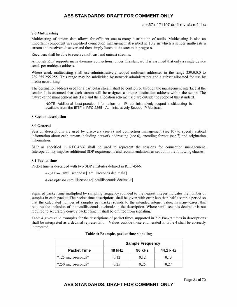
7.6 Multicasting Multicasting of stream data allows for efficient one-to-many distribution of audio. Multicasting is also an important component in simplified connection management described in 10.2 in which a sender multicasts a stream and receivers discover and then simply listen to the stream in progress.
Receivers shall be able to receive multicast and unicast streams.
Although RTP supports many-to-many connections, under this standard it is assumed that only a single device sends per multicast address.
Where used, multicasting shall use administratively scoped multicast addresses in the range 239.0.0.0 to 239.255.255.255. This range may be subdivided by network administrators and a subset allocated for use by media networking.
The destination address used for a particular stream shall be configured through the management interface at the sender. It is assumed that each stream will be assigned a unique destination address within the scope. The nature of the management interface and the allocation scheme used are outside the scope of this standard.
NOTE Additional best-practice information on IP administratively-scoped multicasting is available from the IETF in RFC 2365 - Administratively Scoped IP Multicast.
8 Session description
8.0 General Session descriptions are used by discovery (see 9) and connection management (see 10) to specify critical information about each stream including network addressing (see 6), encoding format (see 7) and origination information.
SDP as specified in RFC 4566 shall be used to represent the sessions for connection management. Interoperability imposes additional SDP requirements and recommendations as set out in the following clauses.
8.1 Packet time Packet time is described with two SDP attributes defined in RFC 4566.
a=ptime:<milliseconds>[.<milliseconds decimal>]
a=maxptime:<milliseconds>[.<milliseconds decimal>]
Signaled packet time multiplied by sampling frequency rounded to the nearest integer indicates the number of samples in each packet. The packet time descriptions shall be given with error less than half a sample period so that the calculated number of samples per packet rounds to the intended integer value. In many cases, this requires the inclusion of the <milliseconds decimal> in the description. Where <milliseconds decimal> is not required to accurately convey packet time, it shall be omitted from signaling.
Table 4 gives valid examples for the descriptions of packet times supported in 7.2. Packet times in descriptions shall be interpreted as a decimal representation. Values outside those enumerated in table 4 shall be correctly interpreted.
Table 4: Example, packet time signaling
Sample Frequency
Packet Time 48 kHz 96 kHz 44,1 kHz
“125 microseconds” 0,12 0,12 0,13
“250 microseconds” 0,25 0,25 0,27

AES STANDARDS: DRAFT FOR COMMENT ONLY
aes67-r-171107-draft-rev-cfc-rc4.doc
Page 22 of 70
AES STANDARDS: DRAFT FOR COMMENT ONLY
“333 microseconds” 0,33 0,33 0,36
“1 millisecond” 1 1 1,09
“4 milliseconds” 4 4 4,35
Descriptions shall include a ptime attribute indicating the desired packet time. If more than one packet time is supported, a maxptime indicating the maximum packet time permitted shall be provided. The interoperable values for the <milliseconds> parameter for both ptime and maxptime are indicated in table 2.
The requirements of this description imply that the shorter packet time is always the preferred packet time. To override the implied assumption that a shorter packet time is always the preferred packet time, the capability negotiation attributes of RFC 5939 may be used to enumerate the supported packet times and order of preference.
If the range of packet times supported includes more than two of the standard packet times (table 2), the description should use the capability negotiation attributes of RFC 5939 to enumerate the supported packet times and order of preference.
NOTE The non-integral-millisecond descriptions may not be correctly understood by connection management partners not in compliance with this standard. The description may need to be confined to integer <millisecond> values when attempting connection to such partners.
8.2 Clock source The ts-refclk attribute specifies the network clock reference used by the stream. ts-refclk supports specification of three versions of PTP in addition to other clock sources. The network clock source for each stream described shall be specified with one or more ts-refclk attributes as specified in RFC 7273.
The following examples illustrate use of the attribute within the scope of synchronization options available in this standard.
EXAMPLE 1 using IEEE 1588-2008 network clock as discussed in 4.1 or 4.2. The GMID in this example is 39-A7-94-FF-FE-07-CB-D0 and the domain is 0:
a=ts-refclk:ptp=IEEE1588-2008:39-A7-94-FF-FE-07-CB-D0:0
EXAMPLE 2 using an IEEE 802.1AS network clock as discussed in 4.3. The GMID in this example is 39-A7-94-FF-FE-07-CB-D0:
a=ts-refclk:ptp=IEEE802.1AS-2011:39-A7-94-FF-FE-07-CB-D0
Although, as discussed in RFC 7273, the PTP domain specification is optional, under this standard, signaling for RTP streams referenced to IEEE 1588-2008 shall indicate both GMID and PTP domain.
IEEE 802.1AS always uses domain 0 so no domain indication is supported or necessary. Two devices synchronized to IEEE 802.1AS shall be assumed to be using the same domain.
Receivers should attempt to connect to senders if they are using the same PTP domain and the same GMID clock reference as the sender. Receivers should not attempt to connect to senders if they are using a different PTP domain for their clock reference than the sender.
The case of a PTP domain match and mismatched GMID may indicate either a transition state of the network or lack of a common clock reference between sender and receiver or different grandmasters referenced to the same traceable clock source (for example, GPS). Receivers may attempt to make a connection in this case but should be prepared for possible synchronization failure.
Under RFC 7273, senders may specify multiple equivalent clock sources. Receivers should evaluate all clock sources specified and should attempt to connect based on the recommendations in this clause.

AES STANDARDS: DRAFT FOR COMMENT ONLY
aes67-r-171107-draft-rev-cfc-rc4.doc
Page 23 of 70
AES STANDARDS: DRAFT FOR COMMENT ONLY
Senders and receivers should monitor for changes in their synchronization status during transmission. Senders should update their clock source description when a change is detected.
When their synchronization status changes or an updated description is received from the sender, receivers should reevaluate their ability to continue receiving according to the recommendations in this clause. Receivers are not required to terminate reception on detection of synchronization signaling mismatch in an ongoing stream but they should be prepared for possible synchronization failure.
8.3 RTP and media clock The relationship of media clock to RTP clock shall be described for each stream with an a=mediaclk:direct=<offset> attribute as specified in RFC 7273 clause 5.2. The offset specification shall be included in the description. A mediaclk attribute shall be provided for each stream described.
NOTE 1 RFC 7273 allows mediaclk to be specified at session, media or source levels. As described in section 5.4 of that document, a declaration at a higher layer satisfies the above requirement for all lower level streams.
NOTE 2 The relationship of media clock to network clock is fixed and specified in 5.
The mediaclk attribute supports numerous media clock scenarios. The following example illustrates use of the attribute within the scope of this standard.
EXAMPLE media clock description - the RTP timestamp has a value of 1810024580 at the media clock epoch:
a=mediaclk:direct=1810024580
8.4 Payload types Allocation of a dynamic payload type and associated rtpmap attribute is required to specify the interoperable encoding formats (table 2) as none of these formats are called out as static payload types in RFC 3551 (clause 6, table 4 of that document). The receiver shall determine the payload type using the rtpmap attribute; it shall not assume any fixed relationship between payload type value and payload type. The relationship is defined on a stream-by-stream basis by senders using the rtpmap attribute.
8.5 Example descriptions
8.5.0 Errata SDP errors in both this standard and in RFC 7273 have been corrected in standard revisions and published errata. It is possible to implement an SDP interpreter to tolerate the resulting errors in earlier implementations. Errors have included invalid t= specification, incorrect a=sendonly specification for multicast stream description, mis-ordered lines and specification of PTP domain with domain-nmbr= syntax.
8.5.1 Multicast session description example Example simple SDP description for 8 channels of 24-bit, 48 kHz audio transmitted as a multicast stream with 1-millisecond packet time.
v=0 o=- 1311738121 1311738121 IN IP4 192.168.1.1 s=Stage left I/O c=IN IP4 239.0.0.1/32 t=0 0 m=audio 5004 RTP/AVP 96 i=Channels 1-8 a=rtpmap:96 L24/48000/8 a=recvonly a=ptime:1 a=ts-refclk:ptp=IEEE1588-2008:39-A7-94-FF-FE-07-CB-D0:0 a=mediaclk:direct=963214424

AES STANDARDS: DRAFT FOR COMMENT ONLY
aes67-r-171107-draft-rev-cfc-rc4.doc
Page 24 of 70
AES STANDARDS: DRAFT FOR COMMENT ONLY
8.5.2 Unicast session description example Example simple SDP description for 8 channels of 24-bit, 48 kHz audio transmitted as a unicast stream with 250-microsecond packet time.
v=0 o=audio 1311738121 1311738121 IN IP4 192.168.1.1 s=Stage left I/O c=IN IP4 192.168.1.1 t=0 0 m=audio 5004 RTP/AVP 96 i=Channels 1-8 a=rtpmap:96 L24/48000/8 a=sendonly a=ptime:0.250 a=ts-refclk:ptp=IEEE1588-2008:39-A7-94-FF-FE-07-CB-D0:0 a=mediaclk:direct=2216659908
9 Discovery Discovery is the network service which allows participants to build a list of the other participants or sessions available on the network. Such a list can be presented to users to assist with connection management. Connection management requires a SIP URI (see 10.1) or SDP description (see 8). These may be delivered through Bonjour, SAP, static configuration or other means.
Devices are not required to implement discovery services. Devices may implement one or more discovery services including Bonjour, SAP and others.
A survey of discovery systems is included in annex E.
10 Connection management
10.0 General Connection management is the procedure and protocols used to establish one or more media streams between a sender and one or more receivers.
10.1 Unicast connections Connection management for unicast streams shall be accomplished using the Session Initiation Protocol (SIP) as defined in RFC 3261. SIP is widely used in IP telephony and is the connection management protocol used by EBU Tech 3326.
As per 7.6, all receivers shall support unicast (and multicast) streaming. It follows from the requirements of this clause that all receivers shall support SIP.
10.1.1 SIP URI Under SIP, audio devices are SIP user agents with an associated SIP URI. SIP allows user agents to locate and make connections to other user agents by referencing the other’s SIP URI. A SIP URI for a potential connection may be learned through discovery (see 9) or through other means (for example: static configuration, proprietary directory service).
The sip: URI form shall be used by this standard. The sips: URI form indicates that connection management should be conducted securely using TLS. Secure connection management does not necessarily imply that stream transmission is done securely. Stream transmission security is negotiated as part of the connection management process. RFC 3261 recommends that user agents implement TLS. However, because this standard does not provide a recommendation for interoperability of secure media streaming (see 6.3), devices may support TLS and sips:, but they are not required for interoperability.

AES STANDARDS: DRAFT FOR COMMENT ONLY
aes67-r-171107-draft-rev-cfc-rc4.doc
Page 25 of 70
AES STANDARDS: DRAFT FOR COMMENT ONLY
10.1.2 Server and serverless modes SIP is conventionally used with the assistance and participation of SIP servers. Different types of servers perform different tasks for a SIP network. Servers may be located anywhere on the network where they are reachable by end stations. The use of servers creates a flexible and scalable connection management system.
Serverless mode is used to perform connection management between user agents in direct peer-to-peer fashion without the intervention of servers. The serverless mode is appropriate for modest installations where, due to limited scale, servers produce minimal benefit and the overhead of installing and configuring SIP servers introduces unnecessary complication.
In order to perform peer-to-peer connection management, the caller must have some means of determining network contact information (that is, host name or IP address) of the callee. This may be obtained through discovery (see 9), manual configuration, or higher-layer protocols. In peer-to-peer connection management, all SIP messages are directed to the target device instead of the server. A device in compliance with this standard shall respond to such requests.
Support for serverless mode does not release devices from requirements to operate in a normal SIP environment featuring servers. Specifically, devices will still need to attempt to discover, and register with, SIP registration servers and respond to messages originating from servers.
10.1.3 User-Agent The User-Agent header field in the SIP protocols is useful for conveying information about the end station that managers can use to expedite connection management and work around implementation-specific issues. The format of User-Agent data is defined in RFC 2616 clause 14.43. Devices should include a User-Agent header field in REGISTER and INVITE messages.
NOTE Security considerations for User-Agent in the context of SIP are discussed in RFC 3261 clause 20.41.
10.1.4 Format negotiation The standard offer/answer model as described in RFC 3264 shall be used to negotiate the encoding format for a connection. Supported encoding formats are described in 7.1.
10.1.5 Packet time negotiation The offer/answer model does not address negotiation of attributes such as packet time. As per 8.1 an offer supporting multiple packet times specifies a range with the ptime and maxptime attributes. An answer shall assume that ptime and maxptime packet times are supported. To increase flexibility and reliability, devices may wish to implement the capability negotiation provisions of RFC 5939.
10.2 Multicast connections Multicast connection management may be accomplished without use of a connection management protocol. In this simple connection management scenario, the receiver is not required to make direct contact with the sender.
A receiver obtains a session description of the desired connection using discovery (see 9) or other means. When a receiver learns of a stream to which it would like to make a connection, it can use IGMP to inform the network of desire to receive and begin receiving the stream.

AES STANDARDS: DRAFT FOR COMMENT ONLY
aes67-r-171107-draft-rev-cfc-rc4.doc
Page 26 of 70
AES STANDARDS: DRAFT FOR COMMENT ONLY
Annex A (Normative) - Media profile
A.0 General The IEEE 1588-2008 precision time protocol was designed to accommodate a range of synchronization applications. The differing requirements of different applications are accommodated through the definition and use of profiles. A profile is a set of operating parameter values and list of protocol components used in service of the application.
The media profile defined in this annex serves the requirements of media networking. Specifically, the profile enables short start-up time, high accuracy and compatibility with standard IP networking equipment.
It is anticipated that additional profiles will be published as the IEEE 1588 ecosystem grows and that some of these will be applicable to media networking. In response to these anticipated advances, devices may choose to implement profiles in addition to or instead of the media profile defined in this annex.
A.1 Media profile description The Media profile specifies attributes and options required and allowed in use of IEEE 1588-2008 in synchronization for media transport under this standard. The basic structure and some of the text in this definition is taken from IEEE 1588-2008 annex J.
The Media profile differs from the Delay Request-Response Default PTP profile given in IEEE 1588-2008 clause J.3 in the following aspects:
• Identification information indicating AES origin of the profile. • portDS.logSyncInterval and portDS.logMinDelayReqInterval are reduced to improve
startup time and improve accuracy when using standard (as opposed to IEEE 1588 enabled) network equipment.
• The only supported message encapsulation is UDP/IPv4 • Clock physical requirements compatible with AES11 • Additional clockClass values to signal AES11 DARS Grade • A recommendation to implement the peer delay mechanism in addition to request-response
A.2 Media profile
A.2.1 Identification The identification values for this PTP profile (see IEEE 1588-2008 clause 19.3.3) are as follows:
PTP Profile: PTP profile for media applications. Version 1.0 Profile identifier: 00-0B-5E-00-01-00 This profile is specified by the AES Standards Committee. A copy may be obtained by ordering AES67-2013 from the AES Standards Store at:
www.aes.org/publications/standards/
A.2.2 PTP attribute values Nodes shall implement all requirements in this PTP profile that specify default values or choices such that these default values or choices apply without requiring user configuration; that is, as delivered from the manufacturer.

AES STANDARDS: DRAFT FOR COMMENT ONLY
aes67-r-171107-draft-rev-cfc-rc4.doc
Page 27 of 70
AES STANDARDS: DRAFT FOR COMMENT ONLY
Table A.1 – attribute values for use with Media profile
Attribute Values defaultDS.domainNumber The default initialization value shall be 0.
All other values (0 to 255) are allowed. portDS.logAnnounceInterval The default initialization value shall be 1.
The configurable range shall be 0 to 4. portDS.logSyncInterval The default initialization value shall be -3.
The configurable range shall be −4 to +1. portDS.logMinDelayReqInterval The default initialization value shall be 0.
The configurable range shall be -3 to 5 or portDS.logSyncInterval to portDS.logSyncInterval+5, whichever is more restrictive.
portDS.logMinPdelayReqInterval The default initialization value shall be 0. The configurable range shall be 0 to 5.
portDS.announceReceiptTimeout The default initialization value shall be 3. The configurable range shall be in the range 2 to 10.
defaultDS.priority1 The default initialization value shall be 128. defaultDS.clockClass Table A.2 specifies additional values beyond those
specified in IEEE 1588-2008 table 5 in support of AES11 physical clock specifications (see A.2.4).
defaultDS.priority2 The default initialization value shall be 128. defaultDS.slaveOnly If this parameter is configurable, the default value shall
be FALSE. transparentClockdefaultDS.primaryDomain The default initialization value shall be 0.
τ (see IEEE 1588-2008 clause 7.6.3.2) The default initialization value shall be 1,0 s.
For each defined range, manufacturers may allow wider ranges.
Table A.2 - clockClass values for use with Media profile
clockClass (decimal)
Specification Time scale
Slave capable
Specific to Media profile
6 A clock that is synchronized to a primary reference time source (for example, GPS)
PTP No No
7 A clock that has previously been designated as clockClass 6 but that has lost the ability to synchronize to a primary reference time source and is in holdover mode and within holdover specifications
PTP No No
13 A clock that is synchronized to an external media clock source
ARB No No

AES STANDARDS: DRAFT FOR COMMENT ONLY
aes67-r-171107-draft-rev-cfc-rc4.doc
Page 28 of 70
AES STANDARDS: DRAFT FOR COMMENT ONLY
14 A clock that has previously been designated as clockClass 13 but that has lost the ability to synchronize to an external media clock source and is in holdover mode and within holdover specifications
ARB No No
52 Degradation alternative A for a clock of clockClass 7 that is not within holdover specification
PTP No No
58 Degradation alternative A for a clock of clockClass 14 that is not within holdover specification
ARB No No
150 A clock whose frequency is synchronized to a reference with ± 1 ppm frequency accuracy (for example, a Grade-1 DARS according to AES11-2009) and whose time has been previously synchronized to a primary reference time source
PTP Yes Yes
158 A clock whose frequency is synchronized to a reference with ± 10 ppm frequency accuracy (for example, a Grade-2 DARS according to AES11-2009) and whose time has been previously synchronized to a primary reference time source
PTP Yes Yes
166 A clock of unspecified tolerance that has been previously synchronized to a primary reference time source
PTP Yes Yes
187 Degradation alternative B for a clock of clockClass 7 that is not within holdover specification
PTP Yes No
193 Degradation alternative B for a clock of clockClass 14 that is not within holdover specification
ARB Yes No
220 A clock whose frequency is synchronized to a reference with ± 1 ppm frequency accuracy (for example, a Grade-1 DARS according to AES11-2009) and whose time has not been previously synchronized to a primary reference time source
ARB Yes Yes
228 A clock whose frequency is synchronized to a reference with ± 10 ppm frequency accuracy (for example, a Grade-2 DARS according to AES11-2009) and whose time has not been previously synchronized to a primary reference time source
ARB Yes Yes
248 Default. This clockClass shall be used if none of the other clockClass definitions apply; for example, a clock of unspecified tolerance that has not been previously synchronized to a primary reference time source.
ARB Yes No
255 A slave-only clock n.a. Yes No
Holdover specification for all clockClass specifications are +/- 5 % of a 96 kHz word-clock period.
A.2.3 PTP options Devices may implement any options of IEEE 1588-2008 clause 17. Devices may implement unicast negotiation as defined in clause 16.1 of IEEE 1588-2008. All of these options shall be inactive unless specifically activated by a management procedure.

AES STANDARDS: DRAFT FOR COMMENT ONLY
aes67-r-171107-draft-rev-cfc-rc4.doc
Page 29 of 70
AES STANDARDS: DRAFT FOR COMMENT ONLY
Node management shall implement the management message mechanism of IEEE 1588-2008.
The best master clock algorithm shall be the algorithm specified by IEEE 1588-2008 clause 9.3.2.
The default path-delay measurement mechanism shall be the delay request-response mechanism specified by IEEE 1588. The peer delay mechanism should also be implemented.
NOTE Only a single mechanism is allowed per link. Boundary clocks should be used between links that use different path delay mechanisms.
A.2.4 Clock physical requirements Clocks shall meet requirements of Grade 2 DARS set forth in AES11 clause 5.2. Clocks may conform to the Grade 1 requirements but in so doing shall indicate this to other network participants as described in A.2.2 defaultDS.clockClass.
NOTE 1 Support for the default IEEE 1588 profile is required; the physical requirements associated with the default must be met when the default profile is in use. Of specific interest in this context is the default profile requirement for a +/- 100 ppm adjustability with a recommendation for +/- 250 ppm adjustability.
NOTE 2 The fact that individual clocks meet AES11 requirements does not guarantee the whole clock distribution system meets AES11 specifications as network performance also contributes to the quality of the distributed clock.

AES STANDARDS: DRAFT FOR COMMENT ONLY
aes67-r-171107-draft-rev-cfc-rc4.doc
Page 30 of 70
AES STANDARDS: DRAFT FOR COMMENT ONLY
Annex B (Informative) - Network QoS configuration recommendations
B.0 General Networks supporting high-performance media streaming must provide the QoS required by these services. This standard recognizes the need for QoS and, in 6.2, specifies how traffic is to be marked for the network. Although network behavior is outside the scope of the standard, this annex gives general configuration guidelines for an IP network with QoS implemented in accordance with IETF DiffServ recommendations.
B.1 DiffServ network configuration DiffServ is a framework for classification and differentiated treatment of network traffic. DiffServ is considered a course-grained QoS architecture as it operates on classes of traffic in aggregate rather than on individual traffic flows.
Per-hop behavior (PHB) is fundamental to DiffServ operation. At each router or switch, traffic is classified and retransmitted according to that classification. In the presence of congestion, higher priority traffic is retransmitted promptly while lower priority traffic waits in buffers inside network equipment and may be discarded altogether. The use of PHBs on classes of traffic, as opposed to individual traffic flows (for example, a media stream) produces a simple and scalable QoS solution.
Ethernet equipment typically supports PHB though use of multiple egress queues per port. Different classes of traffic are queued separately. When an egress port is available to transmit a packet, a selection algorithm selects a packet from one of the queues. There are several selection algorithms in use in network equipment. Arguably the simplest selection algorithm is strict priority. Under this scheme the oldest packet from the highest-priority non-empty queue is selected for transmission. This results in the lowest possible latency for high-priority traffic but can result in lower priority traffic being held off for long periods possibly resulting in lost data, a condition known as starvation. More sophisticated selection algorithms such as weighted round robin and guaranteed minimum bandwidth, address starvation by adding more balance to the process. Under these algorithms, no one is starved for bandwidth but latency for highest priority traffic is higher.
Within a network supporting DiffServ, traffic classes are identified by a 6-bit differentiated services code point (DSCP) value in every IP header. These values are assigned by the end stations generating the traffic as defined in 6.2.
Media streaming under this standard presents three traffic classes to the network. The recommended DSCP values specified in 6.2 for each class are suitable for use on networks configured in accordance with the recommendations in DiffServ RFCs.
NOTE Not all networks are configured in accordance with the DiffServ recommendations. The RFCs allow considerable latitude and consequently, there is considerable variation in how DiffServ is configured and deployed on networks.
B.1.1 Clock Clock traffic consists of relatively low-frequency transmissions (less than 100 packets/second) of small UDP packets (on the order of 100 bytes each) and low bandwidth (less than 100 kbits/second). Although clock traffic is not highly sensitive to packet loss, it is sensitive to latency and specifically to latency variation which is also known among network engineers as delay variation (DV). High levels of DV for clock traffic degrades the accuracy of clock delivery across the network.
It is recommended that IEEE 1588-2008 clock traffic be assigned highest priority for application traffic on the network recognizing that on some networks, network management and routing control traffic are assigned priority higher than any application traffic. On most DiffServ networks, this is achieved by assigning clock traffic to the Expedited Forwarding (EF) class. EF is typically implemented as a strict priority queue that is given transmission preference ahead of other queues.
NOTE EF is often also used for VoIP traffic on the assumption that, compared to previous network applications (file transfers, e-mail deliver, web browsing), VoIP is the most performance-critical network application. However, VoIP typically operates using a 20 ms
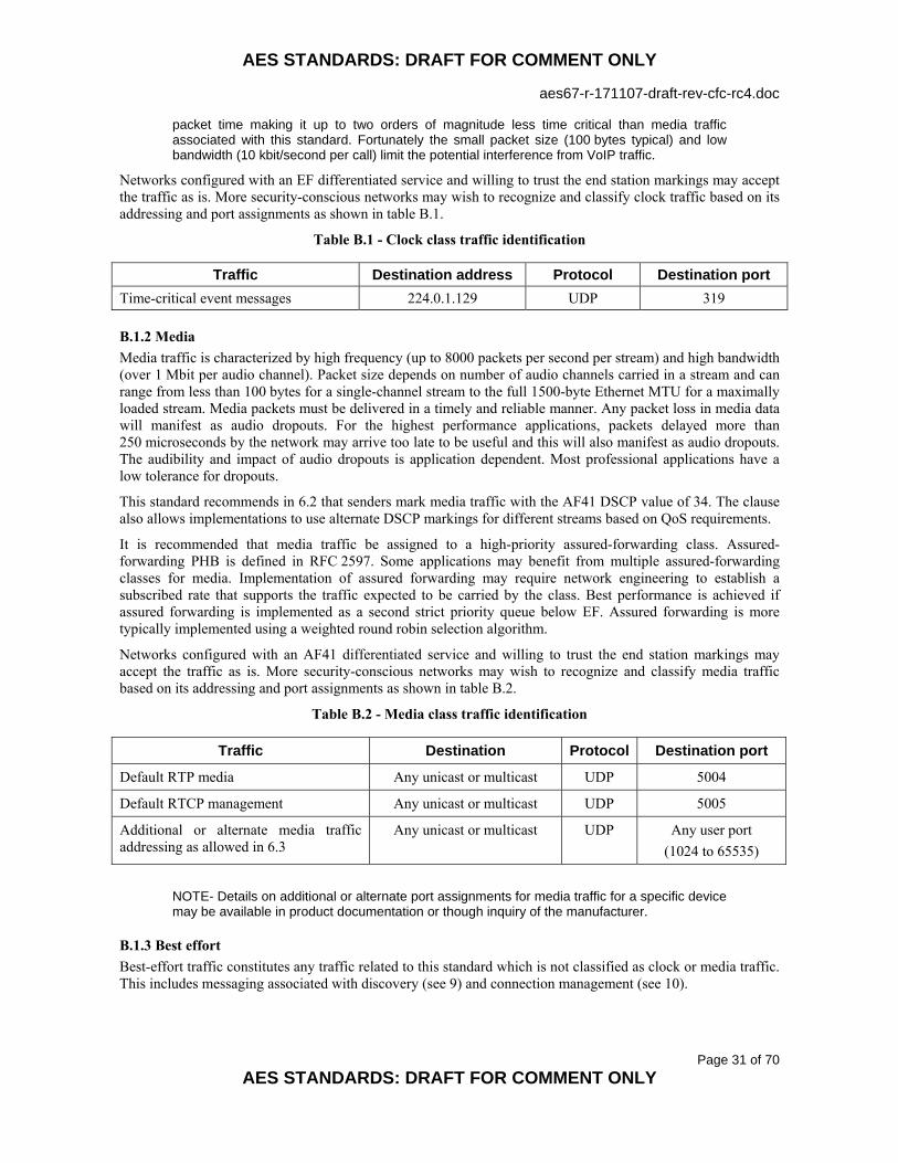
AES STANDARDS: DRAFT FOR COMMENT ONLY
aes67-r-171107-draft-rev-cfc-rc4.doc
Page 31 of 70
AES STANDARDS: DRAFT FOR COMMENT ONLY
packet time making it up to two orders of magnitude less time critical than media traffic associated with this standard. Fortunately the small packet size (100 bytes typical) and low bandwidth (10 kbit/second per call) limit the potential interference from VoIP traffic.
Networks configured with an EF differentiated service and willing to trust the end station markings may accept the traffic as is. More security-conscious networks may wish to recognize and classify clock traffic based on its addressing and port assignments as shown in table B.1.
Table B.1 - Clock class traffic identification
Traffic Destination address Protocol Destination port Time-critical event messages 224.0.1.129 UDP 319
B.1.2 Media Media traffic is characterized by high frequency (up to 8000 packets per second per stream) and high bandwidth (over 1 Mbit per audio channel). Packet size depends on number of audio channels carried in a stream and can range from less than 100 bytes for a single-channel stream to the full 1500-byte Ethernet MTU for a maximally loaded stream. Media packets must be delivered in a timely and reliable manner. Any packet loss in media data will manifest as audio dropouts. For the highest performance applications, packets delayed more than 250 microseconds by the network may arrive too late to be useful and this will also manifest as audio dropouts. The audibility and impact of audio dropouts is application dependent. Most professional applications have a low tolerance for dropouts.
This standard recommends in 6.2 that senders mark media traffic with the AF41 DSCP value of 34. The clause also allows implementations to use alternate DSCP markings for different streams based on QoS requirements.
It is recommended that media traffic be assigned to a high-priority assured-forwarding class. Assured-forwarding PHB is defined in RFC 2597. Some applications may benefit from multiple assured-forwarding classes for media. Implementation of assured forwarding may require network engineering to establish a subscribed rate that supports the traffic expected to be carried by the class. Best performance is achieved if assured forwarding is implemented as a second strict priority queue below EF. Assured forwarding is more typically implemented using a weighted round robin selection algorithm.
Networks configured with an AF41 differentiated service and willing to trust the end station markings may accept the traffic as is. More security-conscious networks may wish to recognize and classify media traffic based on its addressing and port assignments as shown in table B.2.
Table B.2 - Media class traffic identification
Traffic Destination Protocol Destination port
Default RTP media Any unicast or multicast UDP 5004
Default RTCP management Any unicast or multicast UDP 5005
Additional or alternate media traffic addressing as allowed in 6.3
Any unicast or multicast UDP Any user port (1024 to 65535)
NOTE- Details on additional or alternate port assignments for media traffic for a specific device may be available in product documentation or though inquiry of the manufacturer.
B.1.3 Best effort Best-effort traffic constitutes any traffic related to this standard which is not classified as clock or media traffic. This includes messaging associated with discovery (see 9) and connection management (see 10).

AES STANDARDS: DRAFT FOR COMMENT ONLY
aes67-r-171107-draft-rev-cfc-rc4.doc
Page 32 of 70
AES STANDARDS: DRAFT FOR COMMENT ONLY
End stations normally mark best-effort (BE) traffic with the BE DSCP value of 0. Because all networks implement a best effort traffic class and any traffic not otherwise classified is assumed to be best effort, no special configuration is typically required to accommodate BE traffic.

AES STANDARDS: DRAFT FOR COMMENT ONLY
aes67-r-171107-draft-rev-cfc-rc4.doc
Page 33 of 70
AES STANDARDS: DRAFT FOR COMMENT ONLY
Annex C (Informative) – AVB network transport
C.0 General This standard defines how to use an IP transport to carry media data. Ethernet is a common network used to support IP transport. AVB can be viewed as an improved Ethernet. The AVB network is described in a suite of IEEE standards. The standards relevant to network transport are:
• IEEE 802.1AB - Audio Video Bridging (AVB) Systems
• IEEE 802.1Q Clause 34 - Forwarding and queuing for time-sensitive streams
• IEEE 802.1Q Clause 35 - Stream Registration Protocol (SRP)
The AVB improvements can be used to improve performance of media transport. AVB improvements can also be used to improve clock distribution, a topic which is discussed separately in annex D.
C.1 AVB network transport Two basic methods for transmission of interoperable media streams across an AVB network are available.
Transporting interoperable media as an AVB time-sensitive stream makes use of AVB improvements with the restriction that this method of transport must be confined to an AVB network domain and cannot exit to legacy portions of a network that do not support the AVB improvements and thus cannot connect to non-AVB devices.
Transporting interoperable media as “other traffic” allows the flexibility to connect to and through AVB and non-AVB portions of the network and to non-AVB devices. This mode of transport does not make use of AVB’s QoS and registration services and is confined to the proportion of network bandwidth not allocated to time-sensitive streams, typically 25%.
C.1.1 Interoperable media as AVB time-sensitive streams Devices in compliance with this standard that also have AVB capabilities may choose to use AVB bandwidth reservation and QoS provisions for transport of media streams. The advantages of this approach include:
• Reserved bandwidth assures successful media transmission across the network
• Potential compatibility with other AVB devices using IP transport
• Premium bandwidth and latency performance
Devices using this method must be directly connected to an Ethernet switch supporting the AVB standards and protocols. Under AVB, there are two classes of media streams. Class A streams are highest priority and achieve a 2-ms latency guarantee on IEEE 802.1BA compliant networks. Class B streams are lower priority but still higher priority than any other non-stream data on the network. Class B streams achieve a 50-ms latency guarantee on IEEE 802.1BA compliant networks. Either class may be used for interoperable media transport.
Before a device can transmit interoperable media as AVB media traffic, bandwidth must be reserved for the traffic. This is accomplished using the Stream Reservation Protocol described in clause 35 of IEEE 802.1Q. In the reservation, the sender specifies the class of traffic (A or B) and the maximum amount of traffic generated in the measurement interval for that class. The measurement interval is 125 microseconds for class A and 250 microseconds for class B.
Because the AVB network identifies streams by their Ethernet destination addresses, multicast destination addressing is generally used for AVB streams. Interoperable media transmitted should use multicast IP addressing as described in 7.6. Furthermore since, as per RFC 1112, multiple IP multicast addresses are mapped to a single Ethernet multicast address, additional care beyond what is described in 7.6 must be taken when selecting multicast destination addresses for use with AVB time-sensitive streams.

AES STANDARDS: DRAFT FOR COMMENT ONLY
aes67-r-171107-draft-rev-cfc-rc4.doc
Page 34 of 70
AES STANDARDS: DRAFT FOR COMMENT ONLY
C.1.1.1 Sender behavior A sender (talker in AVB terminology) uses SRP to provide the following information to the AVB network in a Talker Advertise message:
StreamID A 64-bit globally-unique identifier comprised of the 48-bit Ethernet MAC address of the sender and 16-bits unique to the device generated by the sender.
Destination address The Ethernet multicast destination address used for stream transmission. VLAN identifier All AVB media packets include an IEEE 802.1Q VLAN tag. The VLAN tag contains
a 12-bit VLAN identifier. The default VLAN identifier for AVB streams is 2. MaxFrameSize The maximum size of the media stream packets created as defined in 7.
MaxFrameSize includes the IP header but excludes any Ethernet overhead. MaxIntervalFrames Maximum number of frames a sender may transmit in one measurement interval.
Since packet times allowed by 7.2 are greater than or equal to AVB measurement intervals, this is always 1.
Data Frame Priority 3 for class A, 2 for class B Rank 1 for normal traffic, 0 for emergency traffic
SRP allocates a fixed amount of bandwidth equal to MaxFrameSize × MaxIntervalFrames per measurement interval. Note that because packet times for interoperable streams are equal to or longer than AVB measurement intervals, actual bandwidth consumed may be significantly less than bandwidth reserved. This should be taken into account in AVB network design.
Senders must receive positive acknowledgement in the form of Listener Ready or Listener Ready Failed from SRP before transmitting stream data packets. Senders transmit stream data packets formatted as IP packets as described in 7. AVB networks use multicast filtering to enforce bandwidth allocation and thus support only multicast destination addressing for stream data (see IEEE 802.1Q clause 35.2.2.8.3). Stream packets transported in this way across an AVB network must therefore use multicast IP destination addressing. The IP multicast destination address is mapped to an Ethernet multicast destination address in the range 01:00:5e:00:00:00 to 01:00:5e:7f:ff:ff according to the procedures of RFC 1112 clause 6.4.
The IP packets are framed into Ethernet packets. The Ethernet framing must include an IEEE 802.1Q VLAN tag with VLAN identifier and priority code point matching the corresponding SRP parameters: VLAN Identifier and Data Frame Priority. Transmission timing of stream data packets within a class by the sender must be in accordance with the credit-based shaper described in IEEE 802.1Q clause 8.6.82.
C.1.1.2 Receiver behavior A receiver (listener in AVB terminology) uses SRP to provide a desired StreamID to the network in a Listener Declaration. If the stream is available, the receiver receives a Talker Advertise and must then send an MVRP membership request to join the VLAN specified in the Talker Advertise. At this point, stream data packets begin to arrive and the receiver should process them in the same manner they are processed on non-AVB networks.
C.1.2 Interoperable media as other traffic Although, an AVB network reserves up to 75% of available bandwidth on each link for media traffic, this allocation is configurable. A larger percentage of bandwidth can be reserved for other traffic. The AVB QoS algorithm known as the credit-based shaper is considerate of other traffic giving it an opportunity to traverse the network each measurement interval. Measurement intervals are 125 microseconds for AVB networks carrying only class A streams and 250 microseconds for networks carrying class B streams or both class A and class B streams. Although other traffic is prioritized below AVB media traffic, the other traffic may be prioritized with

AES STANDARDS: DRAFT FOR COMMENT ONLY
aes67-r-171107-draft-rev-cfc-rc4.doc
Page 35 of 70
AES STANDARDS: DRAFT FOR COMMENT ONLY
respect to itself. All of this creates an acceptable environment for interoperable media to be carried on or through an AVB network as other traffic. The advantages of this approach include:
• No requirement to implement SRP • No requirement to implement credit-based shaper • Ability to transmit media data across the AVB network boundary including bridging media between
separate AVB network domains • Works with or without AVB network equipment • No wasted bandwidth due to mismatch between measurement interval and packet time • No special sender or receiver behavior is required
C.1.2.1 Sender behavior No special sender behavior is required. On some AVB networks, senders may wish to use an IEEE 802.1Q VLAN tag to convey QoS class. AVB networks are generally geared to Ethernet protocols and may not inspect the DSCP value supplied in the IP header.
The VLAN identifier value depends on the VLANs configured on the network. A value of 0 may be used here to indicate default VLAN membership though this use of a 0 VLAN identifier is not supported on all network equipment. Recommended values for the priority field in the VLAN tag are given in table B.3.
Table C.3 - Recommended PCP values for 802.1Q tagged media as “other traffic” through an AVB network
Traffic PCP Clock 6 Media 5
Best effort 0
NOTE PCP values 2 and 3 are used for AVB media traffic and will be remapped to 0 at the AVB domain boundary by the switch as per IEEE 802.1Q Clause 6.9.4.
C.1.2.2 Receiver behavior No special receiver behavior is required. Receivers may wish to be prepared to receive media packets with IEEE 802.1Q tags.

AES STANDARDS: DRAFT FOR COMMENT ONLY
aes67-r-171107-draft-rev-cfc-rc4.doc
Page 36 of 70
AES STANDARDS: DRAFT FOR COMMENT ONLY
Annex D (Informative) - Interfacing to IEEE 802.1AS clock domains
D.0 General IEEE 802.1AS defines a profile for use of IEEE 1588-2008 on enhanced Ethernet networks, as specified in IEEE 802.1BA-2011. This type of networking is commonly known as Audio Video Bridging (AVB). As outlined in clause 4.3, AVB networks may use their native IEEE 802.1AS synchronization profile in place of the profiles otherwise required in clause 4 (the IEEE 1588 default profiles and the Media profile specified in annex A). In many cases it may be desirable to interface the two profiles to build heterogeneous networks using both techniques.
Under both IEEE 1588-2008 and IEEE 802.1AS, a PTP clock is designated as an ordinary clock (OC), boundary clock (BC) or transparent clock (TC) though 802.1AS transparent clocks also have some boundary clock capabilities. A device may implement one or more of these capabilities. PTP clocks have one or more ports. OCs may have as few as one port. TCs and BCs must have two or more ports. Ports on BCs and OCs have an associated operating state, master or slave. An IEEE 1588 profile is associated with each port of a clock. Due to its transparent nature, a TC is able to simultaneously associate itself with multiple clock domains and profiles.
D.1 Boundary clock interface Typically the same profile is used on all ports of a BC but it is also possible to associate different profiles with different ports. A boundary clock running different profiles on different ports creates an interface between portions of an IEEE 1588 network operating with different profiles. The different profiles that may be used for media networking include the default profiles required by this standard and defined in IEEE 1588-2008 annex J, the Media profile recommended by this standard and defined in annex A and the profile used by IEEE 802.1AS on AVB networks.
When a BC is used to communicate synchronization to different network segments in this way, all network segments participate in the Best Master Clock Algorithm (BMCA) and all segments must use the same version of IEEE 1588 protocol and all must use the same domain identifier. Use of BCs in this manner may be appropriate for connecting a segment running the default profile with a segment running the Media profile. Because IEEE 802.1AS uses an Ethernet-specific BMCA this approach is not appropriate for connecting an IEEE 1588 segment to an IEEE 802.1AS segment.
There are no clock source signaling issues when interconnecting clocks in this manner. The interface through the BC simply creates a larger PTP domain. Synchronization identification (see 8) is the same on both sides of the BC interface.
D.2 Ordinary clock interface A multiport OC can run different profiles on different ports. With the following restrictions, a multiport OC can be used to synchronize multiple segments. An OC can have at most one port in slave mode. Clock distribution must be engineered to assure that an OC is not asked to slave to multiple segments and that the desired overall source for synchronization is selected for all networks.
A multiport OC can therefore be used simultaneously as a grandmaster for multiple PTP networks of different types versions and profiles. The utility of this capability is limited by the requirement to collocate grandmasters and by the fact that there is no clock source signaling defined for this type of interconnection.
D.3 Traceable reference Any of the clock sources supported by RFC 7273 can be designated “traceable”. Doing so indicates that the clock is synchronized to the TAI global time reference. In theory, this allows any traceable clock to be used in place of any other traceable source. In practice, there is no means provided for signaling the accuracy of this synchronization. While accuracy of synchronization over a PTP network may be controllable, the accuracy between two traceable references is not specified and generally unknown. An important exception is when both references are GPS. GPS is typically accurate to about 100 nanoseconds, an accuracy comparable to that achieved with PTP. PTP networks with a GPS grandmaster can safely be considered to be operating as identical

AES STANDARDS: DRAFT FOR COMMENT ONLY
aes67-r-171107-draft-rev-cfc-rc4.doc
Page 37 of 70
AES STANDARDS: DRAFT FOR COMMENT ONLY
clocks. The clockClass information broadcast in Announce messages by the grandmaster or available through management messaging gives additional information about the synchronization quality beyond what is available in RFC 7273 signaling.
D.4 AVB network as a boundary clock Because of the high fidelity clock distribution within an IEEE 802.1AS clock domain, it is possible to use the entire IEEE 802.1AS domain as a distributed boundary clock for any other PTP domain. Implementation and the theory behind this capability is discussed in detail in a paper by Geoffrey M. Garner, Michel Ouellette and Michael Johas Teener. Although this technique doesn’t necessarily synchronize the IEEE 802.1AS domain to any of the PTP domains passing through it, it does demonstrate another technique for integrating AVB technology and thus improving interoperability.

AES STANDARDS: DRAFT FOR COMMENT ONLY
aes67-r-171107-draft-rev-cfc-rc4.doc
Page 38 of 70
AES STANDARDS: DRAFT FOR COMMENT ONLY
Annex E (Informative) – Discovery systems E.0 General Although no discovery service is mandated by this standard, clause 9 specifies that potential connections are identified with a SIP URI which can be learned through a discovery system or other means such as a printed directory or link sent via e-mail.
Developers of this standard are aware of the following discovery systems whose application to this standard is discussed below.
E.1 Bonjour Bonjour is a collection of zero-configuration networking techniques developed by Apple Inc. and published as open documents. In the context of discovery, the relevant Bonjour techniques are multicast DNS (mDNS) described in an RFC 6762 and DNS service discovery (DNS-SD) described in an RFC 6763.
If these techniques are used for discovery, RTP sessions should be advertised by their SIP URI as described in IETF draft-lee-sip-dns-sd-uri.
E.2 SAP Use of SAP, or a similar mechanism to distribute SDP descriptions to potential receivers, enables a simplified connection management for multicast streaming (see 10.2).
When SAP is used, SAP version 2 as defined in RFC 2974 should be used. SDP descriptions as defined in 8 should be carried in the payload of SAP messages. Multicast sessions should be announced using destination address as specified in RFC 2974 clause 3; globally scoped multicast sessions are announced using 224.2.127.254 destination address and administratively scoped multicast sessions are announced using the highest address in their scope.
E.3 Axia Discovery Protocol The Axia discovery protocol operates over a system-wide dedicated multicast channel. Every device within the delivery scope for these multicasts and having subscribed to the multicast group, can hear the announcements of all other devices.
All devices periodically generate short presence announcements, and at longer interval, description advertisements. The description advertisements include attributes of the device, as well as a list and attributes of the streams they are able to transmit. When description data is updated, a new advertisement is transmitted without waiting for the next scheduled periodic message. Announcement data allows each participant to build a list of the other participants and streams available on the network, to assist with connection management (10).
E.4 Wheatstone WheatnetIP Discovery Protocol The WheatnetIP discovery protocol operates over a system-wide dedicated IP multicast channel (“announce channel”). Every device within the delivery scope for these multicasts, having subscribed to the multicast group, can hear the announcements of all other devices.
The WheatnetIP protocol uses a Route Master elected from within the nodes in the system. Upon entering a WheatnetIP system, a new device issues an entry announcement (Howdy) on the announce channel. The Route Master acknowledges this message and initiates a roll call, whereby it asks each device in the system, in turn, to multicast its sources and destinations. The Route Master also assigns each device a range of multicast addresses to use for its output streams. Once the device has collected all of the source and destination information, it becomes active within the system. The Route Master periodically polls each device to ensure that all units listed are still in the system.
Since any device can be a Route Master, and every device contains all of the pertinent information to be a Route Master, loss of the Route Master is seamlessly transitioned to a new Route Master.

AES STANDARDS: DRAFT FOR COMMENT ONLY
aes67-r-171107-draft-rev-cfc-rc4.doc
Page 39 of 70
AES STANDARDS: DRAFT FOR COMMENT ONLY
E.5 AMWA NMOS Discovery and Registration Specification (IS-04) The Advanced Media Workflow Association (AMWA) has published a set of Networked Media Open Specifications (NMOS). These include a Discovery and Registration Specification known as AMWA Interface Specification 04 (IS-04).
In IS-04, logical hosts (known as Nodes) register their resources with a Registry. Clients can obtain this information from the Registry through querying or subscription. Clients then access the resources on the Node. For small numbers of Nodes, where a Registry is not available, IS-04 also provides a Peer-to-Peer Discovery mechanism in which each Node directly announces its resources.
The IS-04 specifications (Registration API, Query API, Node API) use protocols aimed at the web, including HTTP(S), WebSockets and JSON. DNS-SD is used for the discovery of the API endpoint. The specifications can be found at: https://github.com/AMWA-TV/nmos-discovery-registration

AES STANDARDS: DRAFT FOR COMMENT ONLY
aes67-r-171107-draft-rev-cfc-rc4.doc
Page 40 of 70
AES STANDARDS: DRAFT FOR COMMENT ONLY
Annex F (Informative) - Glossary F.1 Bonjour Bonjour is Apple's implementation of Zero configuration networking (Zeroconf), a group of technologies that includes service discovery, address assignment, and hostname resolution.
F.2 Domain Name System DNS a hierarchical distributed naming system for computers, services, or any resource connected to the Internet or a private network. See RFC 2474
F.3 DNS Service Discovery DNS-SD a way of using standard DNS programming interfaces, servers, and packet formats to browse the network for services. It is one of the mechanisms used by Bonjour. Source: http://www.dns-sd.org/
F.4 Expedited Forwarding One of the classifications used by DiffServ with the characteristics of low delay, low loss and low jitter. These characteristics are suitable for voice, video and other real-time services. EF traffic is often given strict priority queuing above all other traffic classes.
F.5 Local-area network LAN a computer network that interconnects computers in a limited area such as a home, school, computer laboratory, or office building.
F.6 Multicast DNS mDNS a way of using the Domain Name System (DNS) programming interfaces and packet formats, without configuring a conventional DNS server. It is one of the mechanisms used by Bonjour.
F.7 Ordinary Clock A clock that has a single Precision Time Protocol (PTP) port in a domain and maintains the timescale used in the domain. It may serve as a source of time, that is, be a master clock; or may synchronize to another clock, that is, be a slave clock. Source: IEEE 1588-2008.
F.8 Session Announcement Protocol SAP an experimental protocol for announcing RTP sessions. SAP is defined in RFC 2974.
F.9 Stream reservation protocol SRP the AVB admission control protocol defined in IEEE 802.1Q-2011 clause 35.

AES STANDARDS: DRAFT FOR COMMENT ONLY
aes67-r-171107-draft-rev-cfc-rc4.doc
Page 41 of 70
AES STANDARDS: DRAFT FOR COMMENT ONLY
F.10 UTF-8 A popular variable-length character encoding scheme that supports international character sets but is also backwards compatible with ASCII. UTF-8 is defined in RFC 3629.
F.11 Voice over IP VoIP the communication protocols, technologies, methodologies, and transmission techniques involved in the delivery of voice communications and multimedia sessions over Internet Protocol (IP) networks, such as the Internet.

AES67-xxxx Revision of AES67-2015
aes67-r-171107-draft-rev-cfc-rc4.doc
Page 42 of 70
AES STANDARDS: DRAFT FOR COMMENT ONLY
Annex G (Normative) - Protocol implementation conformance criteria
G.1 Introduction The supplier of an implementation of AES67 that is claimed to conform to the standard shall complete the following PICS proforma.
A completed PICS proforma is the PICS for the implementation in question. The PICS is a statement of which capabilities and options of the protocol have been implemented. The PICS can be used for a variety of purposes by various parties, including the following:
a) As a checklist by the protocol implementer, to reduce the risk of failure to conform to the standard through oversight;
b) As a detailed indication of the capabilities of the implementation, stated relative to the common basis for understanding provided by the standard PICS proforma, by the supplier and acquirer, or potential acquirer, of the implementation;
c) As a basis for initially checking the possibility of interworking with another implementation by the user, or potential user, of the implementation (note that, while interworking can never be guaranteed, failure to interwork can often be predicted from incompatible PICS);
d) As the basis for selecting appropriate tests against which to assess the claim for conformance of the implementation, by a protocol tester.
G.2 Instructions for completing the PICS proforma The first part of the PICS proforma, Implementation Identification and Protocol Summary, is to be completed as indicated with the information necessary to identify fully both the supplier and the implementation.
The main part of the PICS proforma is a fixed-format questionnaire divided into subclauses, each containing one or more items. Answers to the questionnaire items are to be provided in the right-most column, either by simply marking an answer to indicate a restricted choice (usually Yes, No, or Not Applicable), or by entering a value or a set or range of values. (Note that there are some items where two or more choices from a set of possible answers can apply; all relevant choices are to be marked.). As noted in the PICS, some items do not require responses for certain compliant implementations. If no "n/a" response option is given in these cases, the requirement may be removed.
Each item is identified by a statement number reference in the first column that refers directly to a clause number in the standard; the second column describes the feature; the third column contains the level of the requirement (see table G.1); the fourth column indicates the question to be answered. The fifth column is used to record the answer to these questions.
Table G.1 - Requirement levels
Requirement level
Requirement language
1 Shall (requirement)
2 Should (strong suggestion)
3 May (permission)
0 Informative

AES STANDARDS: COMMITTEE USE ONLY - NOT FOR PUBLICATION
aes67-r-171107-draft-rev-cfc-rc4.doc
Page 43 of 70
AES STANDARDS: COMMITTEE USE ONLY - NOT FOR PUBLICATION
43
G.3 PICS proforma
G.3.1 Identification
G.3.1.1 Implementation identification
Supplier (Note 1)
Contact point for queries about the PICS (Note 1)
Implementation Name(s) and Version(s) (Notes 1 and 3)
Other information necessary for full identification - for example, name(s) and version(s) of machines and/or operating system names (Note 2)
NOTE 1 Required for all implementations.
NOTE 2 May be completed as appropriate in meeting the requirements for the identification.
NOTE 3 The terms Name and Version should be interpreted appropriately to correspond with a supplier’s terminology (for example, Type, Series, Model).
G.3.1.2 Protocol summary
Identification of protocol specification AES67-xxxx, AES standard for audio applications of networks - High-performance streaming audio-over-IP interoperability
Identification of amendments and corrigenda to the PICS proforma that have been completed as part of the PICS

AES STANDARDS: COMMITTEE USE ONLY - NOT FOR PUBLICATION
aes67-r-171107-draft-rev-cfc-rc4.doc
Page 44 of 70
AES STANDARDS: COMMITTEE USE ONLY - NOT FOR PUBLICATION
44
G.3.2 Synchronization
G.3.2.1 General
Statement Number
Feature Requirement level
Notes Supported
4.0-1 Synchronization of a common clock shall be achieved using IEEE 1588-2008 Precision Time Protocol (PTP)
1
Mark as supported if the device supports IEEE 1588-2008 Precision Time Protocol (PTP)
Indicate support per operation mode:
• Slave: Yes/No
• Master: Yes/No
Yes [ ] No [ ]
Yes [ ] No [ ]
4.0-2 Devices, except for devices using AVB synchronization (clause 4.3), shall support the IEEE 1588-2008 default profiles as described in annex J.
1 Applicable to non-AVB devices
Mark as supported if the device supports IEEE 1588-2008 default profiles as described in annex J Yes[ ] No [ ] n/a [ ]
4.0-3 Devices using the default profiles shall use IPv4 encapsulation as described in IEEE 1588-2008 annex D. 1 Mark as supported if the device uses IPv4 encapsulation for the default
profiles, as described in IEEE 1588-2008 annex D Yes [ ] No [ ]
G.3.2.2 IP network synchronization
Statement Number
Feature Requirement level
Notes Supported
4.1-1 Devices should support the media profile defined in annex A, to assure adequate performance for all applications on standard IP networks. 2
Mark as supported if the device supports the media profile defined in AES67 annex A.
Note: Marking the media profile as supported neither requires nor implies support for the optional peer delay mechanism. Yes [ ] No [ ]
4.1-2 Devices may use the default profiles on IP networks
0
Device capability information:
Indicate what profile is used on IP networks
Indicate the selection method: permanent / manual / automatic
If automatic, indicate the condition used
[ ]
[ ]
[ ]

AES STANDARDS: COMMITTEE USE ONLY - NOT FOR PUBLICATION
aes67-r-171107-draft-rev-cfc-rc4.doc
Page 45 of 70
AES STANDARDS: COMMITTEE USE ONLY - NOT FOR PUBLICATION
45
G.3.2.3 AVB network synchronization
Statement Number
Feature Requirement level
Notes Supported
4.3-1 AVB networks may use their native IEEE 802.1AS synchronization profile in preference to the default profiles or media profile.
3
Applicable to AVB devices
Mark as supported if the device is capable of using the IEEE 802.1AS synchronization profile.
Indicate the selection method: permanent / manual / automatic
If automatic, indicate the condition used
Yes[ ] No [ ] n/a [ ]
[ ]
[ ]
G.3.3 Media clocks Statement Number
Feature Requirement level
Notes Supported
5-1 The media clock and the network clock shall share the epoch of 1 January 1970 00:00:00 TAI, as defined in IEEE 1588-2008 clause 7.2.2.
1 Mark as supported if the media clock and the network clock share the epoch of 1 January 1970 00:00:00 TAI, as defined in IEEE 1588-2008 clause 7.2.2. Yes [ ] No [ ]
5-2 Digital audio to be carried on the network shall be sampled according to the media clock, or sampling-frequency converted to conform to the media clock.
1 Mark as supported if digital audio is sampled according to the media clock, or sampling-frequency converted to conform to the media clock.
Yes [ ] No [ ]
5-3 The media clock shall advance at an exact rate with respect to the network clock. 1 Mark as supported if the media clock advances at an exact rate with respect
to the network clock. Yes [ ] No [ ]
5-5 The value of the media clock shall be 0 at the IEEE 1588 epoch and change to 1 exactly one sample period after the epoch.
1 Mark as supported if the value of the media clock is 0 at the IEEE 1588 epoch and changes to 1 exactly one sample period after the epoch.
Yes [ ] No [ ]
5-6 The RTP offset shall be conveyed through session description (see 8.3) on a per-stream basis. 1 Mark as supported if RTP offset is conveyed through session description
on a per-stream basis. Yes [ ] No [ ]
5-7 A media clock using 32-bit representation shall accurately take into account all overflows (rollovers) between the epoch and the current time.
1 Mark as supported if the media clock using 32-bit representation accurately takes into account all overflows (rollovers) between the epoch and the current time. Yes [ ] No [ ]

AES STANDARDS: COMMITTEE USE ONLY - NOT FOR PUBLICATION
aes67-r-171107-draft-rev-cfc-rc4.doc
Page 46 of 70
AES STANDARDS: COMMITTEE USE ONLY - NOT FOR PUBLICATION
46
G.3.4 Transport
G.3.4.1 Network layer
Statement Number
Feature Requirement level
Notes Supported
6.1-1 Media packets shall be transported using IP version 4 as defined in RFC 791. 1 Mark as supported if media packets are transported using IP version 4 as
defined in RFC 791. Yes [ ] No [ ]
6.1-2 A receiver that does not support reassembly shall ignore IP packet fragments. 1
Applicable if the receiver does not support IP packet reassembly
Mark as supported if the receiver can safely ignore IP packet fragments Yes[ ] No [ ] n/a [ ]
6.1-3 Senders may set the Don’t Fragment flag (DF) bit in the IP header of outgoing media packets. 3 Mark as supported if the sender sets the Don’t Fragment flag (DF) bit in
the IP header of outgoing media packets. Yes [ ] No [ ]
6.1-4 Senders should terminate transmission of the offending stream in response to receipt of an ICMP “Too Big” message. 2 Mark as supported if the sender terminates transmission of the offending
stream in response to receipt of an ICMP “Too Big” message. Yes [ ] No [ ]
6.1-5 Multicast messaging shall be accomplished using IP multicasting as described in RFC 1112. 1 Mark as supported if multicast messaging is accomplished using IP
multicasting as described in RFC 1112. Yes [ ] No [ ]
6.1-6 All devices shall support IGMPv2 as defined in RFC 2236 1 Mark as supported if the device supports IGMPv2 as defined in RFC 2236. Yes [ ] No [ ]
6.1-7 Devices may support IGMPv3 as defined in RFC 3376. 3 Mark as supported if the device supports IGMPv3 as defined in RFC 3376 Yes [ ] No [ ]
6.1-8 Devices shall use IGMP to request reception of any multicasts required. 1 Mark as supported if the device uses IGMP to request reception of any
multicasts required. Yes [ ] No [ ]
6.1-9 Senders shall use IGMP to request receipt of any multicast media packets they are going to send, before starting to send such packets.
1 Mark as supported if the sender uses IGMP to request receipt of any multicast media packets it is going to send, before starting to send such packets. Yes [ ] No [ ]
G.3.4.2 Quality of service
Statement Number
Feature Requirement level
Notes Supported
6.2-1 Devices shall implement the DiffServ method as described in RFC 2474. 1 Mark as supported if the device implements the DiffServ method as
described in RFC 2474. Yes [ ] No [ ]
6.2-2 The traffic classes given in table 1 shall be supported. 1 Mark as supported if all traffic classes given in table 1 are supported. Yes [ ] No [ ]
6.2-3 Devices shall tag outgoing traffic with an appropriate DSCP value 1 Mark as supported if the device tags outgoing traffic with an appropriate
DSCP value Yes [ ] No [ ]

AES STANDARDS: COMMITTEE USE ONLY - NOT FOR PUBLICATION
aes67-r-171107-draft-rev-cfc-rc4.doc
Page 47 of 70
AES STANDARDS: COMMITTEE USE ONLY - NOT FOR PUBLICATION
47
6.2-4 Devices should use the default values for the DSCP field as given in table 1. 2 Mark as supported if the device uses the default values without requiring
user configuration. Yes [ ] No [ ]
6.2-5 Although not required, devices may implement a management interface for DSCP configuration, allowing traffic to be marked with alternative DSCP values.
3 Mark as supported if DSCP field can be configured for one or more traffic classes defined in Table 1 through any means.
Indicate what configuration means are provided
Yes [ ] No [ ]
[ ]
6.2-6 Devices not implementing a management interface shall use the default values exclusively. 1
Applicable if the device does not implement a management interface for DSCP configuration
Mark as supported if the device uses the default values exclusively. Yes[ ] No [ ] n/a [ ]
6.2-7 Senders may be configured to use the same DSCP values for multiple classes. 3
Test applicable if DSCP values are configurable
Mark as supported if the device implements a method to configure the same DSCP values for multiple classes. Yes[ ] No [ ] n/a [ ]
6.2-8 Senders may be configured to use classes in addition to those shown in table 1. 3 Mark as supported if the device implements a method to configure
additional traffic classes Yes [ ] No [ ]
6.2-9 Senders should mark outgoing RTCP packets with the same DSCP value as the respective RTP stream packets. 2
Mark as supported if the sender marks outgoing RTCP packets with the same DSCP value as the respective RTP stream packets.
Note: Senders are not required to implement RTCP Yes [ ] No [ ] n/a [ ]
6.2-10 Receivers should mark outgoing RTCP packets with the same DSCP value they would use on RTP packets if transmitting a similar stream. 2
Mark as supported if the receiver marks outgoing RTCP packets with the same DSCP value it would use on RTP packets if transmitting a similar stream.
Note: Receivers are not required to implement RTCP Yes [ ] No [ ] n/a [ ]
6.2-11 Receivers shall make no assumptions about class associations from DSCP markings on received packets. 1 Mark as supported if DSCP markings on received packets do not have an
impact on performance of the device. Yes [ ] No [ ]
G.3.4.3 Transport layer
Statement Number
Feature Requirement level
Notes Supported
6.3-1 Devices shall use Real-time Transport Protocol as defined in RFC 3550. 1 Mark as supported if the device uses Real-time Transport Protocol as
defined in RFC 3550. Yes [ ] No [ ]
6.3-2 Devices shall operate in accordance with RTP Profile for Audio and Video Conferences with Minimal Control as defined in RFC 3551.
1 Mark as supported if the device operates in accordance with RTP Profile for Audio and Video Conferences with Minimal Control as defined in RFC 3551. Yes [ ] No [ ]

AES STANDARDS: COMMITTEE USE ONLY - NOT FOR PUBLICATION
aes67-r-171107-draft-rev-cfc-rc4.doc
Page 48 of 70
AES STANDARDS: COMMITTEE USE ONLY - NOT FOR PUBLICATION
48
6.3-3 Devices should use the default port allocated for RTP: 5004 2 Mark as supported if the device uses the default port allocated for RTP: 5004 Yes [ ] No [ ]
6.3-4 Devices should use the default port allocated for RTCP: 5005 2
Mark as supported if the device uses the default port allocated for RTCP: 5005
Note: Devices are not required to implement RTCP Yes [ ] No [ ] n/a [ ]
6.3-5a Senders may use other or additional ports.
3
Mark as supported if the sender is capable to use for RTP or RTCP any other port different from the default ports, either fixed or configurable through the management interface or another method
If different ports are used, indicate which
Yes [ ] No [ ]
[ ]
6.3-5b Receivers shall support use of other or additional ports by corresponding senders. 1
Mark as supported if the receiver supports use of other or additional ports by the corresponding sender, different from the default ports, configurable through the management interface or another method. Yes [ ] No [ ]
6.3-6 Devices shall use UDP as defined in RFC 768 for transport of RTP. 1 Mark as supported if the device uses UDP as defined in RFC 768 for
transport of RTP. Yes [ ] No [ ]
6.3-7 The maximum allowed RTP payload size shall be 1440 bytes, when no contributing source (CSRC) identifiers or header extensions are included.
1 Mark as supported if the RTP payload size does not exceed 1440 bytes, when no contributing source (CSRC) identifiers or header extensions are included. Yes [ ] No [ ]
6.3-8 Senders should not include contributing source (CSRC) identifiers in the RTP header. 2 Mark as supported if the sender does not include contributing source
(CSRC) identifier in the RTP header. Yes [ ] No [ ]
6.3-9 Senders should not add RTP header extensions. 2 Mark as supported if the sender does not add RTP header extensions. Yes [ ] No [ ]
6.3-10 Receivers shall tolerate the presence of CSRC identifiers and header extensions.
1
Mark as supported if in presence of CSRC and/or header extensions in an audio stream:
• receiver continues normal operation, and no adverse effect on any of its functions is observed, and
• no adverse effect on audio received with the same stream is observed Yes [ ] No [ ]
6.3-10a If senders include header extensions or CSRCs, the 1440 maximum allowed payload shall be adjusted downwards by the size of the added header material.
1 Mark as supported if the RTP payload size does not exceed 1440 bytes adjusted downwards by the size of the added header material, when contributing source (CSRC) identifiers or header extensions are included. Yes [ ] No [ ] n/a [ ]
6.3-11 Both senders and receivers should transmit RTCP messages as specified in RFC 3550 clause 6. 2 Mark as supported if the device transmits RTCP messages as specified in
RFC 3550 clause 6. Yes [ ] No [ ]

AES STANDARDS: COMMITTEE USE ONLY - NOT FOR PUBLICATION
aes67-r-171107-draft-rev-cfc-rc4.doc
Page 49 of 70
AES STANDARDS: COMMITTEE USE ONLY - NOT FOR PUBLICATION
49
6.3-12 Senders and receivers should allocate RTCP bandwidth as recommended in RFC 3551 clause 2 (RTCP report interval). 2 Mark as supported if the device allocates RTCP bandwidth as
recommended in RFC 3551 clause 2 (RTCP report interval). Yes [ ] No [ ] n/a [ ]
6.3-13 Unicast senders should monitor connectivity to their respective receivers in such a way as to detect failure of the receiver and stop transmission within 60 seconds.
2 Mark as supported if the unicast sender stops transmission to a missing receiver within 60 seconds.
Yes [ ] No [ ]
6.3-14 For monitoring of receivers that do not implement RTCP, senders may use any other monitoring means available to them including any of the following techniques.
SIP session timers as described in RFC 4028
SIP OPTION ping (see IETF draft-jones-sip-options-ping)
ICMP Echo request (ping)
0
Sender capability information: Indicate what monitoring means are used.
[ ]
G.3.5 Encoding and streaming Statement Number
Feature Requirement level
Notes Supported
7 Encoding and streaming Indicate support per operation mode:
• Device supports receiving:
• Device supports sending: Note: Devices are allowed to implement only receiving or only sending. When testing such devices, remove the unimplemented sending or receiving requirements from the qualification criteria described throughout this section.
See G.4 for explanation of qualification criteria.
Yes [ ] No [ ]
Yes [ ] No [ ]

AES STANDARDS: COMMITTEE USE ONLY - NOT FOR PUBLICATION
aes67-r-171107-draft-rev-cfc-rc4.doc
Page 50 of 70
AES STANDARDS: COMMITTEE USE ONLY - NOT FOR PUBLICATION
50
G.3.5.1 Payload format and sampling rate
Statement Number
Feature Requirement level
Notes Supported
7.1-1 All devices shall support 48 kHz sampling rate.
1
Mark as supported if the device supports all the following capabilities as defined in Table G.2:
• T1.1 or T1.2
• R1.1
• R1.2 Yes [ ] No [ ]
7.1-2 Devices should support 96 kHz sampling rate.
2
Mark as supported if the device supports all the following capabilities as defined in Table G.2:
• T1.3
• R1.3 Yes [ ] No [ ]
7.1-3 Devices should support 44,1 kHz sampling rate.
2
Mark as supported if the device supports all the following capabilities as defined in Table G.2:
• T1.4
• R1.4 Yes [ ] No [ ]
7.1-4 At 48 kHz sampling rate: Receivers shall support both L16 and L24 encodings
1
Mark as supported if the device supports all the following capabilities as defined in Table G.2:
• R1.1
• R1.2
Note: This test verifies the “Receive” subset of stream modes verified in clause 7.1-1. Yes [ ] No [ ]
7.1-5 At 48 kHz sampling rate: Senders shall support either L16, or L24, or both encodings
1
Mark as supported if the device supports all the following capabilities as defined in Table G.2:
• T1.1 or T1.2
Indicate if L16 (T1.2), or L24 (T1.1), or both are supported
Note: This test verifies the “Transmit” subset of stream modes verified in clause 7.1-1. [ ]
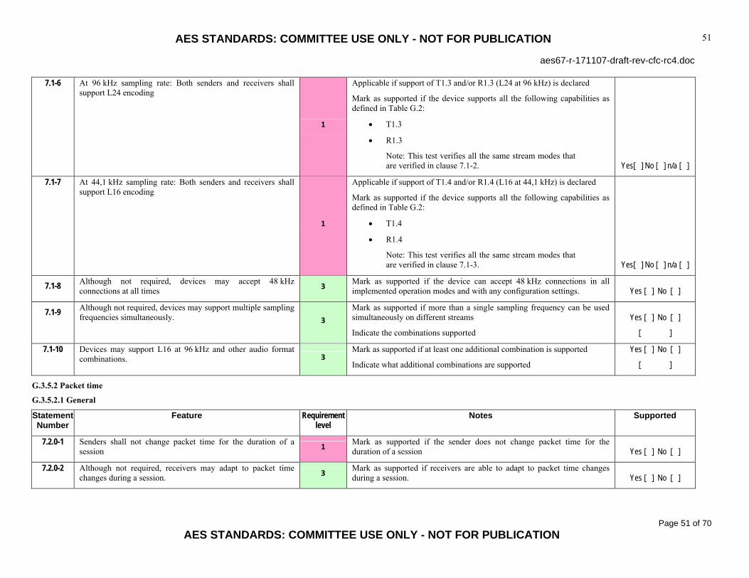
AES STANDARDS: COMMITTEE USE ONLY - NOT FOR PUBLICATION
aes67-r-171107-draft-rev-cfc-rc4.doc
Page 51 of 70
AES STANDARDS: COMMITTEE USE ONLY - NOT FOR PUBLICATION
51
7.1-6 At 96 kHz sampling rate: Both senders and receivers shall support L24 encoding
1
Applicable if support of T1.3 and/or R1.3 (L24 at 96 kHz) is declared
Mark as supported if the device supports all the following capabilities as defined in Table G.2:
• T1.3
• R1.3
Note: This test verifies all the same stream modes that are verified in clause 7.1-2. Yes[ ] No [ ] n/a [ ]
7.1-7 At 44,1 kHz sampling rate: Both senders and receivers shall support L16 encoding
1
Applicable if support of T1.4 and/or R1.4 (L16 at 44,1 kHz) is declared
Mark as supported if the device supports all the following capabilities as defined in Table G.2:
• T1.4
• R1.4
Note: This test verifies all the same stream modes that are verified in clause 7.1-3. Yes[ ] No [ ] n/a [ ]
7.1-8 Although not required, devices may accept 48 kHz connections at all times 3 Mark as supported if the device can accept 48 kHz connections in all
implemented operation modes and with any configuration settings. Yes [ ] No [ ]
7.1-9 Although not required, devices may support multiple sampling frequencies simultaneously. 3
Mark as supported if more than a single sampling frequency can be used simultaneously on different streams
Indicate the combinations supported
Yes [ ] No [ ]
[ ]
7.1-10 Devices may support L16 at 96 kHz and other audio format combinations. 3
Mark as supported if at least one additional combination is supported
Indicate what additional combinations are supported
Yes [ ] No [ ]
[ ]
G.3.5.2 Packet time
G.3.5.2.1 General
Statement Number
Feature Requirement level
Notes Supported
7.2.0-1 Senders shall not change packet time for the duration of a session 1 Mark as supported if the sender does not change packet time for the
duration of a session Yes [ ] No [ ]
7.2.0-2 Although not required, receivers may adapt to packet time changes during a session. 3 Mark as supported if receivers are able to adapt to packet time changes
during a session. Yes [ ] No [ ]

AES STANDARDS: COMMITTEE USE ONLY - NOT FOR PUBLICATION
aes67-r-171107-draft-rev-cfc-rc4.doc
Page 52 of 70
AES STANDARDS: COMMITTEE USE ONLY - NOT FOR PUBLICATION
52
7.2.0-3 Receivers should not rely on the presence or accuracy of any packet time description. Receivers should be able to determine packet time based on the timestamps in received packets.
2 Mark as supported if streams are correctly received when no or incorrect packet time description is provided
Yes [ ] No [ ]
7.2.0-5 Product documentation for a device shall indicate which packet times are supported in send and receive directions. 1 Mark as supported if product documentation indicates which packet times
are supported in send and receive directions. Yes [ ] No [ ]
G.3.5.2.2 Required packet time
Statement Number
Feature Requirement level
Notes Supported
7.2.1-1 Senders shall be able to load each audio packet with 48 samples of audio data when operating at a sampling frequency of 48 kHz.
1 Mark as supported if the device supports all the following capabilities as defined in Table G.3:
• T2.1; applied to 48-kHz stream modes only Yes [ ] No [ ]
7.2.1-2 Senders shall be able to load each audio packet with 48 samples of audio data when operating at a sampling frequency of 44,1 kHz. 1
Applicable if support of T1.4 (L16 at 44,1 kHz) is declared
Mark as supported if the device supports all the following capabilities as defined in Table G.3:
• T2.1; applied to 44,1-kHz stream modes only Yes[ ] No [ ] n/a [ ]
7.2.1-3 Senders shall be able to load each audio packet with 96 samples when operating at a sampling frequency of 96 kHz.
1
Applicable if support of T1.3 (L24 at 96 kHz) is declared
Mark as supported if the device supports all the following capabilities as defined in Table G.3:
• T2.1; applied to 96 kHz stream modes only Yes[ ] No [ ] n/a [ ]
7.2.1-4 Receivers shall be able to receive and decode 48-sample packets when operating at a sampling frequency of 48 kHz. 1
Mark as supported if the device supports all the following capabilities as defined in Table G.3:
• R2.1; applied to 48 kHz stream modes only Yes[ ] No [ ]
7.2.1-5 Receivers shall be able to receive and decode 48-sample packets when operating at a sampling frequency of 44,1 kHz.
1
Applicable if support of R1.4 (L16 at 44,1 kHz) is declared
Mark as supported if the device supports all the following capabilities as defined in Table G.3:
• R2.1; applied to 44,1 kHz stream modes only Yes[ ] No [ ] n/a [ ]
7.2.1-6 Receivers shall be able to receive and decode 96-sample packets when operating at a sampling frequency of 96 kHz.
1
Applicable if support of R1.3 (L24 at 96 kHz) is declared
Mark as supported if the device supports all the following capabilities as defined in Table G.3:
• R2.1; applied to 96-kHz stream modes only Yes[ ] No [ ] n/a [ ]

AES STANDARDS: COMMITTEE USE ONLY - NOT FOR PUBLICATION
aes67-r-171107-draft-rev-cfc-rc4.doc
Page 53 of 70
AES STANDARDS: COMMITTEE USE ONLY - NOT FOR PUBLICATION
53
7.2.1-7 Although not required, devices may accept “1 millisecond” (48-sample at 48 kHz or 44,1 kHz, or 96-sample at 96 kHz) connections at all times.
3 Mark as supported if the device can accept “1 millisecond” connections in all implemented operation modes and with any configuration settings.
Yes [ ] No [ ]
7.2.1-8 Although not required, devices may support multiple packet times simultaneously. 3
Mark as supported if multiple packet times can be used simultaneously
Indicate which packet times are simultaneously supported in which mode
Yes [ ] No [ ]
[ ]
G.3.5.2.3 Recommended packet times
Statement Number
Feature Requirement level
Notes Supported
7.2.2-1 Senders and receivers should support one or more of the other packet times listed in Table 2.
2
Applicable if support of any non-1ms packet times listed in Table 2 is declared
Mark as supported if the device supports at least one of the following capability sets as defined in Table G.3:
• T2.2 and R2.2
• T2.3 and R2.3
• T2.4 and R2.4
• T2.5 and R2.5
Indicate which of the recommended packet times is/are supported
Yes[ ] No [ ] n/a [ ]
[ ]
7.2.2-2 Senders and receivers may support additional packet times.
3
Applicable if support of any packet times not listed in Table G.3 is declared
Mark as supported if the device supports the following capability set:
• T2.6 and R2.6, at least one packet time common for the sender and the receiver
Indicate what additional packet time(s) is/are supported
Yes[ ] No [ ] n/a [ ]
[ ]
G.3.5.3 Stream channel count
Statement Number
Feature Requirement level
Notes Supported
7.3-1 Receivers shall support reception of streams with 1 to 8 audio channels 1
Mark as supported if the device supports all the following capabilities as defined in Table G.4:
• All R3.1 to R3.8 Yes [ ] No [ ]

AES STANDARDS: COMMITTEE USE ONLY - NOT FOR PUBLICATION
aes67-r-171107-draft-rev-cfc-rc4.doc
Page 54 of 70
AES STANDARDS: COMMITTEE USE ONLY - NOT FOR PUBLICATION
54
7.3-2 Receivers may support streams with more than 8 channels.
3
Mark as supported if the device supports all the following capabilities as defined in Table G.4:
• R3.9
Indicate what additional stream channel counts (greater than 8) are supported
Yes [ ] No [ ]
[ ]
7.3-3 Senders shall be able to offer at least one stream with 8 channels or fewer.
1
Mark as supported if the device supports all the following capabilities as defined in Table G.4:
• At least one of T3.1 to T3.8
Indicate what stream channel count(s) (8 or smaller) is/are supported
Yes [ ] No [ ]
[ ]
7.3-4 Senders may support streams with more than 8 channels.
3
Mark as supported if the device supports all the following capabilities as defined in Table G.4:
• T3.9
Indicate what additional stream channel counts (greater than 8) are supported
Yes [ ] No [ ]
[ ]
G.3.5.4 Link offset
Statement Number
Feature Requirement level
Notes Supported
7.4-1 RTP packets are marked with origination timestamps in the timestamp field (RFC 3550 clause 5.1), referenced at ingress to the sender network system.
1
Mark as supported if the origination timestamps in RTP packets appear between:
• time when audio producing the first sample in the packet enters the sender, and
• time when the network packet carrying it leaves the sender, minus one packet time.
Note: Accuracy of conformance verification is limited by the inability to observe events inside the device. Yes [ ] No [ ]

AES STANDARDS: COMMITTEE USE ONLY - NOT FOR PUBLICATION
aes67-r-171107-draft-rev-cfc-rc4.doc
Page 55 of 70
AES STANDARDS: COMMITTEE USE ONLY - NOT FOR PUBLICATION
55
7.4-2 A receiver should attempt to maintain a constant link offset.
2
Mark as supported if the receiver:
• maintains a constant link offset during stable reception
• recovers to the previous link offset when resuming reception after occasional stream interruptions
Note: The receiver may change the link offset as a reaction to changes in network conditions, for example, changed propagation delay or jitter. Such reaction is not a reason to disqualify the device in this test. Yes [ ] No [ ]
7.4-3 The link offset and any changes in link offset should be communicated to the management entity within the receiver, if present.
2 Applicable if there is a management entity in the device.
Mark as supported if the link offset and any changes in link offset are communicated to the management entity within the receiver. Yes [ ] No [ ] n/a [ ]
G.3.5.5 Sender timing and receiver buffering
Statement Number
Feature Requirement level
Notes Supported
7.5-1 Receivers shall have a buffer capacity at least 3 times the packet time. 1 Mark as supported if verified for all supported packet times
Yes [ ] No [ ]
7.5-2 Receivers should have a buffer capacity at least 20 times the packet time or 20 ms whichever is smaller. 2 Mark as supported if verified for all supported packet times
Yes [ ] No [ ]
7.5-3 Receiver capability information 0 Indicate the maximum supported size of the receive buffer in milliseconds [ ]
7.5-4 Senders should transmit at the nominal transmission time with a variation of 1 packet time or less. 2 Mark as supported if verified for all supported packet times
Yes [ ] No [ ]
7.5-5 Senders shall transmit data at the nominal transmission time with a variation of no more than 17 packet times or 17 ms whichever is smaller.
1 Mark as supported if verified for all supported packet times
Yes [ ] No [ ]
7.5-6 Sender capability information 0 Indicate the transmission timing tolerance in milliseconds [ ]

AES STANDARDS: COMMITTEE USE ONLY - NOT FOR PUBLICATION
aes67-r-171107-draft-rev-cfc-rc4.doc
Page 56 of 70
AES STANDARDS: COMMITTEE USE ONLY - NOT FOR PUBLICATION
56
G.3.5.6 Multicasting
Statement Number
Feature Requirement level
Notes Supported
7.6-1 Receivers shall be able to receive multicast and unicast streams.
NOTE This requirement is reiterated in clause 10.1 of the standard.
1
Mark as supported if the device can be configured to receive, concurrently or non- concurrently, both:
• multicast streams in at least one mode within the scope of AES67
• and unicast streams in at least one mode within the scope of AES67 Yes [ ] No [ ]
7.6-2 Where used, multicasting shall use administratively scoped multicast addresses in the range 239.0.0.0 to 239.255.255.255
1
Mark as supported if verified ability:
• to receive streams marked with any multicast destination addresses in the entire range 239.0.0.0 to 239.255.255.255, and
• to mark output packets with any multicast destination addresses in the entire range 239.0.0.0 to 239.255.255.255, when sending Yes [ ] No [ ]
7.6-3 The destination address used for a particular stream shall be configured through the management interface at the sender. 1 Mark as supported if the destination address used for a particular stream
can be configured through the management interface at the sender. Yes [ ] No [ ]
G.3.6 Session description
G.3.6.1 General
Statement Number
Feature Requirement level
Notes Supported
8.0-1 SDP as specified in RFC 4566 shall be used to represent the sessions for connection management 1
Mark as supported when verified for both SDP output generation and SDP input interpretation with at least one connection management mechanism, which may be different for unicast connections and multicast connections. Yes [ ] No [ ]
G.3.6.2 Packet time
Statement Number
Feature Requirement level
Notes Supported
8.1-1 The packet time descriptions shall be given with error less than half a sample period. 1 Mark as supported if verified for all supported packet times
Yes [ ] No [ ]

AES STANDARDS: COMMITTEE USE ONLY - NOT FOR PUBLICATION
aes67-r-171107-draft-rev-cfc-rc4.doc
Page 57 of 70
AES STANDARDS: COMMITTEE USE ONLY - NOT FOR PUBLICATION
57
8.1-2 Where decimal representation is not required to accurately convey packet time, it shall be omitted from signaling 1 Mark as supported if verified for all supported packet times
Yes [ ] No [ ]
8.1-3 Packet times in descriptions shall be interpreted as a decimal representation. 1 Mark as supported if verified for all supported packet times
Yes [ ] No [ ]
8.1-4 Values outside those enumerated in table 4 shall be correctly interpreted.
1
Mark as supported if the device correctly interprets the following alternative decimal representations of packet times listed in Table 4, as long as they do not produce an incorrect calculated integer sample count:
• containing unnecessary decimal point
• containing unnecessary precision digits, whether they are correct or incorrect with respect to the exact fractional value Yes [ ] No [ ]
8.1-5 Descriptions shall include a ptime attribute indicating the desired packet time. 1
Test applicable both to multicast signaling and to SIP negotiation
Mark as supported if ptime is given in generated SDP in all relevant tests Yes [ ] No [ ]
8.1-6 If more than one packet time is supported, a maxptime indicating the maximum packet time permitted shall be provided. 1
Test applicable to SIP negotiation
Test applicable to devices that support more than one packet time
Mark as supported if maxptime is given in generated SDP in all relevant tests Yes [ ] No [ ] n/a [ ]
8.1-7 To override the implied assumption that a shorter packet time is always the preferred packet time, the capability negotiation attributes of RFC 5939 may be used to enumerate the supported packet times and order of preference. 3
Test applicable to SIP negotiation
Test applicable to devices that support more than one packet time
Mark as supported if the capability negotiation attributes of RFC 5939 are used to enumerate the supported packet times and order of preference in at least one test scenario. Yes [ ] No [ ] n/a [ ]
8.1-8 If the range of packet times supported includes more than two of the standard packet times (table 2), the description should use the capability negotiation attributes of RFC 5939 to enumerate the supported packet times and order of preference. 2
Test applicable to SIP negotiation
Test applicable to devices that support more than two of the standard packet times
Mark as supported if the capability negotiation attributes of RFC 5939 are used to enumerate the supported packet times and order of preference in all relevant tests. Yes [ ] No [ ] n/a [ ]

AES STANDARDS: COMMITTEE USE ONLY - NOT FOR PUBLICATION
aes67-r-171107-draft-rev-cfc-rc4.doc
Page 58 of 70
AES STANDARDS: COMMITTEE USE ONLY - NOT FOR PUBLICATION
58
G.3.7 Clock source Statement Number
Feature Requirement level
Notes Supported
8.2-1 The network clock source for each stream described shall be specified with one or more ts-refclk attributes as specified in RFC 7273.
1 Test applicable both to multicast signaling and to SIP negotiation
Mark as supported if included in output SDP and correctly interpreted on input Yes [ ] No [ ]
8.2-2 Signaling for RTP streams referenced to IEEE 1588-2008 shall indicate both GMID and PTP domain. 1
Test applicable both to multicast signaling and to SIP negotiation
Mark as supported if included in output SDP and correctly interpreted on input Yes [ ] No [ ]
8.2-3 Receivers should attempt to connect to senders if they are using the same PTP domain and the same GMID clock reference as the sender.
2 Mark as supported if receiver connects to a sender, which uses the same PTP domain and GMID clock reference.
Yes [ ] No [ ]
8.2-4 Receivers should not attempt to connect to senders if they are using a different PTP domain for their clock reference than the sender.
2 Mark as supported if receiver does not attempt connection to a sender which uses different PTP domain.
Yes [ ] No [ ]
8.2-5 Receivers may attempt to make a connection in case of PTP domain match and mismatched GMID 3 Mark as supported if receiver connects to a sender which uses the same
PTP domain and different GMID Yes [ ] No [ ]
8.2-6 Receivers attempting to make a connection in case of PTP domain match and mismatched GMID should be prepared for possible synchronization failure. 2
Mark as supported if a receiver connecting to a sender, which uses the same PTP domain and different GMID, is capable of detecting and reacting to the possible synchronization failure by invoking a signaling mechanism and/or disconnecting the faulty connection. Yes [ ] No [ ]
8.2-8 Senders should monitor for changes in their synchronization status during transmission and update their clock source description when a change is detected
2 Mark as supported if clock source description is updated in the SDP generated by Sender
Yes [ ] No [ ]
8.2-9 Receivers should monitor for changes in their synchronization status during reception. When their synchronization status changes, receivers should reevaluate their ability to continue receiving according to the recommendations in this clause
2
Test applicable to receivers that refuse connections in case of PTP domain or GMID mismatch (clauses 8.2-4 and 8.2-5)
Mark as supported if the following is verified, when the receiver synchronization status changes:
• receiver disconnects from a previously connected sender when the PTP domain or when GMID becomes different, following behavior equivalent to that observed on this device, when setting up new connections (clauses 8.2-4 and 8.2-5) Yes[ ] No [ ] n/a [ ]

AES STANDARDS: COMMITTEE USE ONLY - NOT FOR PUBLICATION
aes67-r-171107-draft-rev-cfc-rc4.doc
Page 59 of 70
AES STANDARDS: COMMITTEE USE ONLY - NOT FOR PUBLICATION
59
8.2-10 Receivers should monitor for changes in their synchronization status during reception. When an updated description is received from the sender, receivers should reevaluate their ability to continue receiving according to the recommendations in this clause 2
Test applicable to receivers that refuse connections in case of PTP domain or GMID mismatch (8.2-4 to 8.2-5)
Mark as supported if the following is verified, when an updated description is received from the sender:
• receiver disconnects from a previously connected sender when the PTP domain or when GMID becomes different, following behavior equivalent to that observed on this device, when setting up new connections (clauses 8.2-4 and 8.2-5) Yes[ ] No [ ] n/a [ ]
8.2-11 Receivers are not required to terminate reception on detection of synchronization signaling mismatch in an ongoing stream. 0 Receiver capability information: Indicate what behavior is implemented [ ]
8.2-12 Receivers continuing reception on detection of synchronization signaling mismatch in an ongoing stream should be prepared for possible synchronization failure.
2
Test applicable to receivers that would attempt to continue reception under the given conditions.
Mark as supported if the receiver, which is continuing receiving under these conditions, is capable of detecting and reacting to the possible synchronization failure by invoking a signaling mechanism and/or disconnecting the faulty connection. Yes[ ] No [ ] n/a [ ]
G.3.7.1 RTP and media clock
Statement Number
Feature Requirement level
Notes Supported
8.3-1 The relationship of media clock to RTP clock shall be described for each stream with an a=mediaclk:direct=<offset> attribute as specified in RFC 7273 clause 5.2.
1
Mark as supported when verified for both SDP output generation and SDP input interpretation.
Yes [ ] No [ ]
G.3.7.2 Payload types
Statement Number
Feature Requirement level
Notes Supported
8.4-1 The receiver shall determine the payload type using the rtpmap attribute; it shall not assume any fixed relationship between payload type value and payload type.
1 Mark as supported when verified for SDP input interpretation.
Yes [ ] No [ ]

AES STANDARDS: COMMITTEE USE ONLY - NOT FOR PUBLICATION
aes67-r-171107-draft-rev-cfc-rc4.doc
Page 60 of 70
AES STANDARDS: COMMITTEE USE ONLY - NOT FOR PUBLICATION
60
G.3.8 Discovery Statement Number
Feature Requirement level
Notes Supported
9-1 Devices may implement one or more discovery services including Bonjour, SAP and others. 3
Mark as supported if at least one discovery service is implemented
Indicate what discovery services are implemented
Yes [ ] No [ ]
[ ]
G.3.9 Connection management
G.3.9.1 Unicast connections
Statement Number
Feature Requirement level
Notes Supported
10.1-1 Connection management for unicast streams shall be accomplished using the Session Initiation Protocol (SIP) as defined in RFC 3261.
1 Mark as supported if SIP can be used to set up a connection. Verification of completeness of the SIP implementation is outside the scope of this PICS. Yes [ ] No [ ]
G.3.9.1.1 SIP URI
Statement Number
Feature Requirement level
Notes Supported
10.1.1-1 The “sip: ” URI form shall be used as defined in RFC 3261 1 Mark as supported if the “sip: ” URI form is used as defined in RFC 3261 Yes [ ] No [ ]
10.1.1-2 Devices may support TLS and “sips: ”, but they are not required for interoperability. 0 Device capability information: Indicate support of TLS and “sips:”
Yes [ ] No [ ]
G.3.9.1.2 Server and serverless modes
Statement Number
Feature Requirement level
Notes Supported
10.1.2-1 In addition to serverless mode, devices shall be able to operate in a normal SIP environment featuring servers – attempt to discover, and register with, SIP registration servers, and respond to messages originating from servers.
1
Mark as supported if devices can operate in a normal SIP environment featuring servers attempt to discover, and register with, SIP registration servers, and respond to messages originating from servers.
Yes [ ] No [ ]
10.1.2-2 A device in conformance with this standard shall respond to SIP messages sent directly from other user agents. 1
Mark as supported if the device responds to SIP messages sent directly from other user agents.
Note: Serverless mode Yes [ ] No [ ]

AES STANDARDS: COMMITTEE USE ONLY - NOT FOR PUBLICATION
aes67-r-171107-draft-rev-cfc-rc4.doc
Page 61 of 70
AES STANDARDS: COMMITTEE USE ONLY - NOT FOR PUBLICATION
61
G.3.9.1.3 User-Agent
Statement Number
Feature Requirement level
Notes Supported
10.1.3-1 Devices should include a User-Agent header field in REGISTER and INVITE messages. 2 Mark as supported if the device includes a User-Agent header field in
REGISTER and INVITE messages. Yes [ ] No [ ]
G.3.9.1.4 Format negotiation
Statement Number
Feature Requirement level
Notes Supported
10.1.4-1 The standard offer/answer model as described in RFC 3264 shall be used to negotiate the encoding format for a connection.
1 Mark as supported if the standard offer/answer model as described in RFC 3264 is used to negotiate the encoding format for a connection.
Yes [ ] No [ ]
G.3.9.1.5 Packet time negotiation
Note: No new requirements are specified in this clause. The relevant functionality is covered by tests in clauses 8.1-7 and 8.1-8
G.3.9.2 Multicast connections
Statement Number
Feature Requirement level
Notes Supported
10.2-1 Multicast connection management may be accomplished without use of a connection management protocol. 3
Mark as supported if a connection can be set up without a connection management protocol
Indicate what connection management method is implemented
Yes [ ] No [ ]
[ ]
G.3.10 Media profile (Normative) G.3.10.1 General
Statement Number
Feature Requirement level
Notes Supported
A.0-1 Devices may choose to implement profiles in addition to or instead of the media profile defined in this annex.
3
Mark as supported if the device implements any other than the default and media profiles
Indicate all profiles that are implemented in addition to the mandatory default profile
Yes [ ] No [ ]
[ ]
G.3.11 Media profile All tests in this section are applicable only if the media profile is supported (test item 4.1-1)

AES STANDARDS: COMMITTEE USE ONLY - NOT FOR PUBLICATION
aes67-r-171107-draft-rev-cfc-rc4.doc
Page 62 of 70
AES STANDARDS: COMMITTEE USE ONLY - NOT FOR PUBLICATION
62
G.3.11.1.1 Identification
Statement Number
Feature Requirement level
Notes Supported
A.2.1-1 Profile identification: PTP profile for media applications. Version 1.0. Profile identifier: 00-0B-5E-00-01-00.
1
Applicable to devices using the AES67 media profile
Mark as supported if profile identifier is indicated in profileIdentity field of management messages (IEEE 1588 15.5.3.1.2.10) as “00-0B-5E-00-01-00” Yes[ ] No [ ] n/a [ ]
G.3.11.1.2 Table A.1 - PTP attribute values
Statement Number
Feature Requirement level
Notes Supported
A.2.2-1 Nodes shall implement all requirements in this PTP profile that specify default values or choices such that these default values or choices apply without requiring user configuration, as delivered from the manufacturer.
1
Mark as supported if the device implements all requirements in this PTP profile that specify default values or choices such that these default values or choices apply without requiring user configuration, as delivered from the manufacturer. Yes [ ] No [ ]
A.2.2-2 For each defined range, manufacturers may allow wider ranges. 3 Mark as supported if a wider range is allowed for at least one of the PTP
attributes Yes [ ] No [ ]
A.2.2-3 defaultDS.domainNumber default 0 1 Mark as supported if the default initialization value of defaultDS.domainNumber is 0 Yes [ ] No [ ]
A.2.2-4 defaultDS.domainNumber range 0-255 1 Mark as supported if all other values (0 to 255) are allowed Yes [ ] No [ ]
A.2.2-5 portDS.logAnnounceInterval default 1 1 Mark as supported if the default initialization value of portDS.logAnnounceInterval is 1 Yes [ ] No [ ]
A.2.2-6 portDS.logAnnounceInterval range 0 to 4 1
Mark as supported if the required range is supported
Indicate the wider range, if allowed by the implementation
Yes [ ] No [ ]
[ ]
A.2.2-7 portDS.logSyncInterval default –3 1 Mark as supported if the default initialization value of portDS.logSyncInterval is –3 Yes [ ] No [ ]
A.2.2-8 portDS.logSyncInterval range -4 to +1 1
Mark as supported if the required range is supported
Indicate the wider range, if allowed by the implementation
Yes [ ] No [ ]
[ ]

AES STANDARDS: COMMITTEE USE ONLY - NOT FOR PUBLICATION
aes67-r-171107-draft-rev-cfc-rc4.doc
Page 63 of 70
AES STANDARDS: COMMITTEE USE ONLY - NOT FOR PUBLICATION
63
A.2.2-9 portDS.logMinDelayReqInterval default 0 1 Mark as supported if the default initialization value of portDS.logMinDelayReqInterval is 0 Yes [ ] No [ ]
A.2.2-10 portDS.logMinDelayReqInterval range -3 to 5
-- OR --
<portDS.logSyncInterval> to <portDS.logSyncInterval>+5
whichever is more restrictive
1
Mark as supported if the required range is supported
Indicate the wider range, if allowed by the implementation
Yes [ ] No [ ]
[ ]
A.2.2-11 portDS.logMinPdelayReqInterval default 0 1 Mark as supported if the default initialization value of portDS.logMinPdelayReqInterval is 0
A.2.2-12 portDS.logMinPdelayReqInterval range 0 to 5 1
Mark as supported if the required range is supported
Indicate the wider range, if allowed by the implementation
Yes [ ] No [ ]
[ ]
A.2.2-11 portDS.announceReceiptTimeout default 3 1 Mark as supported if the default initialization value of portDS.announceReceiptTimeout is 3 Yes [ ] No [ ]
A.2.2-14 portDS.announceReceiptTimeout range 2 to 10 1
Mark as supported if the required range is supported
Indicate the wider range, if allowed by the implementation
Yes [ ] No [ ]
[ ]
A.2.2-15 defaultDS.priority1 default 128 1 Mark as supported if the default initialization value of defaultDS.priority1 is 128 Yes [ ] No [ ]
A.2.2-16 defaultDS.priority2 default 128 1 Mark as supported if the default initialization value of defaultDS.priority2 is 128 Yes [ ] No [ ]
A.2.2-17 defaultDS.slaveOnly default FALSE 1
Test applicable to devices that support slave/master mode configuration
Mark as supported if the default initialization value of defaultDS.slaveOnly is FALSE
Yes [ ] No [ ]
[ ]
A.2.2-18 transparentClockdefaultDS.primaryDomain default 0 1 Mark as supported if the default initialization value of
transparentClockdefaultDS.primaryDomain is 0 Yes [ ] No [ ]
A.2.2-19 τ default 1,0 s 1 Mark as supported if the default initialization value of τ (see IEEE 1588-2008 clause 7.6.3.2) is 1,0 s Yes [ ] No [ ]

AES STANDARDS: COMMITTEE USE ONLY - NOT FOR PUBLICATION
aes67-r-171107-draft-rev-cfc-rc4.doc
Page 64 of 70
AES STANDARDS: COMMITTEE USE ONLY - NOT FOR PUBLICATION
64
G.3.11.1.3 Table A.2 values
Statement Number
Feature Requirement level
Notes Supported
A.2.2-20 Holdover specification for all clockClass specifications are +/- 5 % of a 96 kHz word-clock period. 0 Applies to all tests referring to the holdover mode
A.2.2-21 defaultDS.clockClass 6 - synchronized to a primary reference time source (for example, GPS)
0
Applicable to devices supporting primary reference time source (for example, GPS)
Mark as supported if the device supports clockClass 6 according to IEEE 1588-2008 clause 7.6.2.4 and table 5 Yes[ ] No [ ] n/a [ ]
A.2.2-22 defaultDS.clockClass 7 ‐ defaultDS.clockClass 6 in holdover
0
Applicable to devices supporting primary reference time source (for example, GPS)
Mark as supported if the device supports clockClass 7 according to IEEE 1588-2008 clause 7.6.2.4 and table 5, and the holdover specification given in AES67-2015 clause A.2.2 (PICS clause A.2.2-20). Yes[ ] No [ ] n/a [ ]
A.2.2-23 defaultDS.clockClass 13 - synchronized to an external media clock source 0
Applicable to devices supporting external media clock sources
Mark as supported if the device supports clockClass 13 according to IEEE 1588-2008 clause 7.6.2.4 and table 5. Yes[ ] No [ ] n/a [ ]
A.2.2-24 defaultDS.clockClass 14 ‐ defaultDS.clockClass 13 in holdover
0
Applicable to devices supporting external media clock sources
Mark as supported if the device supports clockClass 14 according to IEEE 1588-2008 clause 7.6.2.4 and table 5, and the holdover specification given in AES67-2015 clause A.2.2 (PICS clause A.2.2-20). Yes[ ] No [ ] n/a [ ]
A.2.2-25 defaultDS.clockClass 52 - degradation alternative A for a clock of clockClass 7 that is not within holdover specification 0
Applicable to devices supporting primary reference time source (for example, GPS)
Mark as supported if the device supports clockClass 52 according to IEEE 1588-2008 clause 7.6.2.4 and table 5, and the holdover specification given in AES67-2015 clause A.2.2 (PICS clause A.2.2-20). Yes[ ] No [ ] n/a [ ]
A.2.2-26 defaultDS.clockClass 58 - degradation alternative A for a clock of clockClass 14 that is not within holdover specification 0
Applicable to devices supporting external media clock sources
Mark as supported if the device supports clockClass 58 according to IEEE 1588-2008 clause 7.6.2.4 and table 5, and the holdover specification given in AES67-2015 clause A.2.2 (PICS clause A.2.2-20). Yes[ ] No [ ] n/a [ ]

AES STANDARDS: COMMITTEE USE ONLY - NOT FOR PUBLICATION
aes67-r-171107-draft-rev-cfc-rc4.doc
Page 65 of 70
AES STANDARDS: COMMITTEE USE ONLY - NOT FOR PUBLICATION
65
A.2.2-27 defaultDS.clockClass 150 - A clock whose frequency is synchronized to a reference with ± 1 ppm frequency accuracy (for example, a Grade-1 DARS according to AES11-2009) and whose time has been previously synchronized to a primary reference time source
0
Applicable to devices which support a frequency reference and are capable of synchronizing to a primary reference time source either directly or indirectly as a PTP slave.
Mark as supported if the device:
• in absence of the intended primary reference time source, can synchronize (fall back) to a frequency reference source
• indicates defaultDS.clockClass value 150, when, being previously synchronized to a primary reference time source, is now synchronized to a reference with ± 1 ppm frequency accuracy (for example, a Grade-1 DARS according to AES11-2009)
• conforms to the relevant requirements of IEEE 1588-2008 clause 7.6.2.4 and table 5 Yes[ ] No [ ] n/a [ ]
A.2.2-28 defaultDS.clockClass 158 - A clock whose frequency is synchronized to a reference with ± 10 ppm frequency accuracy (for example, a Grade-2 DARS according to AES11-2009) and whose time has been previously synchronized to a primary reference time source
0
Applicable to devices which support a frequency reference and are capable of synchronizing to a primary reference time source either directly or indirectly as a PTP slave.
Mark as supported if the device:
• in absence of the intended primary reference time source, can synchronize to a frequency source (fall back to syntonized operation)
• indicates defaultDS.clockClass value 158, when, being previously synchronized to a primary reference time source, is now synchronized to a reference with ± 10 ppm frequency accuracy (for example, a Grade-2 DARS according to AES11-2009)
• conforms to the relevant requirements of IEEE 1588-2008 clause 7.6.2.4 and table 5 Yes[ ] No [ ] n/a [ ]

AES STANDARDS: COMMITTEE USE ONLY - NOT FOR PUBLICATION
aes67-r-171107-draft-rev-cfc-rc4.doc
Page 66 of 70
AES STANDARDS: COMMITTEE USE ONLY - NOT FOR PUBLICATION
66
A.2.2-29 defaultDS.clockClass 166 - A clock of unspecified tolerance that has been previously synchronized to a primary reference time source
0
Applicable to devices which are capable of synchronizing to a primary reference time source either directly or indirectly as a PTP slave.
Mark as supported if the device:
• indicates defaultDS.clockClass value 166, when, being previously synchronized to a primary reference time source, is now of unspecified tolerance
• conforms to the relevant requirements of IEEE 1588-2008 clause 7.6.2.4 and table 5 Yes[ ] No [ ] n/a [ ]
A.2.2-30 defaultDS.clockClass 187 - degradation alternative B for a clock of clockClass 7 that is not within holdover specification 0
Applicable to devices supporting primary reference time source (for example, GPS)
Mark as supported if the device supports clockClass 187 according to IEEE 1588-2008 clause 7.6.2.4 and table 5, and the holdover specification given in AES67-2015 clause A.2.2 (PICS clause A.2.2-20). Yes[ ] No [ ] n/a [ ]
A.2.2-31 defaultDS.clockClass 193 - degradation alternative B for a clock of clockClass 14 that is not within holdover specification 0
Applicable to devices supporting external media clock sources
Mark as supported if the device supports clockClass 193 according to IEEE 1588-2008 clause 7.6.2.4 and table 5, and the holdover specification given in AES67-2015 clause A.2.2 (PICS clause A.2.2-20). Yes[ ] No [ ] n/a [ ]
A.2.2-32 defaultDS.clockClass 220 ‐ A clock whose frequency is synchronized to a reference with ± 1 ppm frequency accuracy (for example, a Grade-1 DARS according to AES11-2009) and whose time has not been previously synchronized to a primary reference time source
0
Applicable to devices supporting frequency reference source
Mark as supported if the device:
• indicates defaultDS.clockClass value 220, when, not being previously synchronized to a primary reference time source, is synchronized to a reference with ± 1 ppm frequency accuracy (for example, a Grade-1 DARS according to AES11-2009)
• conforms to the relevant requirements of IEEE 1588-2008 clause 7.6.2.4 and table 5
• Yes[ ] No [ ] n/a [ ]

AES STANDARDS: COMMITTEE USE ONLY - NOT FOR PUBLICATION
aes67-r-171107-draft-rev-cfc-rc4.doc
Page 67 of 70
AES STANDARDS: COMMITTEE USE ONLY - NOT FOR PUBLICATION
67
A.2.2-33 defaultDS.clockClass 228 ‐ A clock whose frequency is synchronized to a reference with ± 10 ppm frequency accuracy (for example, a Grade- 2 DARS according to AES11-2009) and whose time has not been previously synchronized to a primary reference time source
0
Applicable to devices supporting frequency reference source
Mark as supported if the device:
• indicates defaultDS.clockClass value 228, when, not being previously synchronized to a primary reference time source, is synchronized to a reference with ± 10 ppm frequency accuracy (for example, a Grade-2 DARS according to AES11-2009)
• conforms to the relevant requirements of IEEE 1588-2008 clause 7.6.2.4 and table 5
• Yes[ ] No [ ] n/a [ ]
A.2.2-34 defaultDS.clockClass 248 – default
0
Applicable to devices supporting master operation, if none of the other clockClass definitions apply
Mark as supported if the device supports clockClass 248 according to IEEE 1588-2008 clause 7.6.2.4 and table 5. Yes[ ] No [ ] n/a [ ]
A.2.2-35 defaultDS.clockClass 255 - a slave only clock 0
Applicable to slave-only clocks (defaultDS.slaveOnly is TRUE)
Mark as supported if the device supports clockClass 255 according to IEEE 1588-2008 clause 7.6.2.4 and table 5. Yes[ ] No [ ] n/a [ ]
G.3.11.1.4 PTP options
Statement Number
Feature Requirement level
Notes Supported
A.2.3-1 Devices may implement any options of IEEE 1588-2008 clause 17. 3
Mark as supported if at least one option is implemented
Indicate the implemented options
Yes [ ] No [ ]
[ ]
A.2.3-2 Devices may implement unicast negotiation as defined in clause 16.1 of IEEE 1588-2008. 3 Mark as supported if the device implements unicast negotiation as defined
in clause 16.1 of IEEE 1588-2008. Yes [ ] No [ ]
A.2.3-3 IEEE 1588 clause 16.1 and 17 options shall be inactive unless specifically activated by a management procedure. 1 Mark as supported if IEEE 1588 clause 16.1 and 17 options are inactive
unless specifically activated by a management procedure. Yes [ ] No [ ]
A.2.3-4 Node management shall implement the management message mechanism of IEEE 1588-2008. 1 Mark as supported if node management implements the management
message mechanism of IEEE 1588-2008. Yes [ ] No [ ]
A.2.3-5 The best master clock algorithm shall be the algorithm specified by IEEE 1588-2008 clause 9.3.2. 1 Mark as supported if the best master clock algorithm is the algorithm
specified by IEEE 1588-2008 clause 9.3.2. Yes [ ] No [ ]

AES STANDARDS: COMMITTEE USE ONLY - NOT FOR PUBLICATION
aes67-r-171107-draft-rev-cfc-rc4.doc
Page 68 of 70
AES STANDARDS: COMMITTEE USE ONLY - NOT FOR PUBLICATION
68
A.2.3-6 The default path-delay measurement mechanism shall be the delay request-response mechanism specified by IEEE 1588. 1 Mark as supported if the default path-delay measurement mechanism is the
delay request-response mechanism specified by IEEE 1588. Yes [ ] No [ ]
A.2.3-7 The peer delay mechanism should also be implemented. 2 Mark as supported if the peer delay mechanism is also implemented. Yes [ ] No [ ]
G.3.11.1.5 Clock physical requirements
Statement Number
Feature Requirement level
Notes Supported
A.2.4-1 Clocks shall meet requirements of Grade 2 DARS set forth in AES11 clause 5.2. 1 Mark as supported if the clock meets requirements of Grade 2 DARS set
forth in AES11 clause 5.2. Yes [ ] No [ ]
A.2.4-2 Clocks may conform to the Grade 1 requirements. 3 Mark as supported if the clock conforms to the Grade 1 requirements. Yes [ ] No [ ]

AES67-xxxx Revision of AES67-2015
aes67-r-171107-draft-rev-cfc-rc4.doc
Page 69 of 70
AES STANDARDS: DRAFT FOR COMMENT ONLY
G.4 – Qualification criteria for encoding and streaming capabilities Stream modes are described by a number of attributes, namely:
• a combination of encoding and sampling rate • packet time • channel count
Devices may, or may not implement specific attribute values, which determines their level of conformance. All attribute values as used for conformance testing purposes are listed in Tables G.2 to G.3 and enumerated as “Tx.x” for stream transmit and “Rx.x” for stream receive capabilities.
The manufacturer of the device under test declares attribute values that are to be included in conformance testing. Attribute values that are not declared are considered not implemented and ignored during conformance testing.
A specific attribute value (capability) is considered supported if it is verified in combination with all declared values of all other attributes. An exception must be made for modes that would exceed the maximal allowed RTP payload size 1440 bytes. Each of the enumerated capabilities needs to be tested only once, while allowing references to it from multiple clauses.
Table G.2 - Encoding and sampling rate attributes
Transmit Receive T1.1 L24 at 48 kHz R1.1 L24 at 48 kHz T1.2 L16 at 48 kHz R1.2 L16 at 48 kHz T1.3 L24 at 96 kHz R1.3 L24 at 96 kHz T1.4 L16 at 44,1 kHz R1.4 L16 at 44,1 kHz
Table G.3 - Packet time attributes
Transmit Receive T2.1 1 ms R2.1 1 ms T2.2 0,125 ms R2.2 0,125 ms T2.3 0,250 ms R2.3 0,250 ms T2.4 0,333 ms R2.4 0,333 ms T2.5 4 ms R2.5 4 ms T2.6 one or more other R2.6 one or more other
Table G.4 - Channel count attributes
Transmit Receive T3.1 1 R3.1 1 T3.2 2 R3.2 2 T3.3 3 R3.3 3 T3.4 4 R3.4 4 T3.5 5 R3.5 5 T3.6 6 R3.6 6 T3.7 7 R3.7 7 T3.8 8 R3.8 8 T3.9 one or more higher than 8 R3.9 one or more higher than 8

AES STANDARDS: COMMITTEE USE ONLY - NOT FOR PUBLICATION
aes67-r-171107-draft-rev-cfc-rc4.doc
Page 70 of 70
AES STANDARDS: COMMITTEE USE ONLY - NOT FOR PUBLICATION
70
Annex H Bibliography
AES5-2008, AES recommended practice for professional digital audio - Preferred sampling frequencies for applications employing pulse-code modulation. Audio Engineering Society, New York, NY., US.
IEEE 802.1BA, Audio Video Bridging (AVB) Systems, Institute of Electrical and Electronics Engineers (IEEE), US.
IEEE 802.1Q-2011, Media Access Control (MAC) Bridges and Virtual Bridged Local Area Networks, Institute of Electrical and Electronics Engineers (IEEE), US.
IEEE 802.1AS, Timing and Synchronization for Time-Sensitive Applications in Bridged Local Area Networks, Institute of Electrical and Electronics Engineers (IEEE), US.
RFC 792 - Internet Control Message Protocol, Internet Engineering Task Force
RFC 894 - A Standard for the Transmission of IP Datagrams over Ethernet Networks, Internet Engineering Task Force
RFC 2597, Assured Forwarding PHB Group, Internet Engineering Task Force
RFC 3170, IP Multicast Applications: Challenges and Solutions, Internet Engineering Task Force
RFC 4028 – Session Timers in the Session Initiation Protocol (SIP), Internet Engineering Task Force
EBU Tech 3326, Audio contribution over IP - Requirements for Interoperability, European Broadcasting Union, Geneva, Switzerland
RFC 6762, Multicast DNS, Internet Engineering Task Force
RFC 6763, DNS-Based Service Discovery, Internet Engineering Task Force
RFC 7272, Inter-Destination Media Synchronization (IDMS) Using the RTP Control Protocol (RTCP), Internet Engineering Task Force
draft-lee-sip-dns-sd-uri, SIP URI Service Discovery using DNS-SD, Internet Engineering Task Force. http://datatracker.ietf.org/doc/draft-lee-sip-dns-sd-uri/
draft-jones-sip-options-ping, Using OPTIONS to Query for Operational Status in the Session Initiation Protocol (SIP), Internet Engineering Task Force. http://datatracker.ietf.org/doc/draft-jones-sip-options-ping/
Geoffrey M. Garner, Michel Ouellette and Michael Johas Teener (2012-09-27). "Using an IEEE 802.1AS Network as a Distributed IEEE 1588 Boundary, Ordinary, or Transparent Clock". 2010 International IEEE Symposium on Precision Clock Synchronization for Measurement Control and Communication (ISPCS) (IEEE).
IS-04 NMOS Discovery & Registration, Advanced Media Workflow Association (AMWA), http://www.amwa.tv/projects/IS-04.shtml