Äspö hard rock laboratory - skb · Äspö hard rock laboratory prototype repository project...
TRANSCRIPT

Svensk Kärnbränslehantering ABSwedish Nuclear Fueland Waste Management CoBox 5864SE-102 40 Stockholm SwedenTel +46 8 459 84 00Fax +46 8 661 57 19
Äspö Hard Rock Laboratory
Prototype Repository
Project description
FIKW-CT-2000-00055
Christer Svemar
Svensk Kärnbränslehantering AB
Roland Pusch
Geodevelopment AB
November 2000
InternationalProgress Report
IPR-00-30
Report no. No.
IPR-00-30 F63KAuthor Date
R Pusch, C Svemar 2000-11-15Checked by Date
Steering CommitteeApproved Date
Christer Svemar 2001-03-14
Keywords: Backfill, buffer, canister, chemistry, expansive clay, groundwater, heater,hydration, instrumentation, KBS-3, monitoring, piezometry, pressures, repository, rock,SKB, temperature
This report concerns a study which was conducted for SKB. The conclusionsand viewpoints presented in the report are those of the author(s) and do notnecessarily coincide with those of the client.
Äspö Hard Rock Laboratory
Prototype Repository
Project description
FIKW-CT-2000-00055
Christer Svemar
Svensk Kärnbränslehantering AB
Roland Pusch
Geodevelopment AB
November 2000
2 (59)
ABSTRACT
The Prototype Repository Project is an international, EC-supported activity with the objective to investigate, on a full scale, the integrated performance of engineered barriers and near-field rock of a simulated deep repository in crystalline rock with respect to heat evolution, mechanics, water permeation, water chemistry, gas evolution and microbial processes under natural and realistic conditions at approximately 450 m depth below the ground surface. The test site is a 65 m long TBM-bored drift from which six 1.75 m diameter deposition holes extend downwards to about 8 m depth in accordance with the KBS-3 concept. The outer 25 m long part has two holes and is separated from the inner 40 m long one, which has 4 holes, and from the rest of the underground laboratory by stiff and tight plugs. The deposition holes will contain genuine copper/steel canisters with heaters for simulating the warming caused by the radioactive decay. The canisters will be embedded in dense buffer clay consisting of blocks of compacted bentonite powder, and the drift will be backfilled with clayey soil. The instrumentation makes it possible to record major processes in the rock, buffer and backfill, like piezometric and porewater pressures, wetting/drying of the buffer and backfill, temperature evolution in the buffer and backfill and surrounding rock, effective and total pressures and displacements in the buffer and backfill and surrounding rock, gas accumulation in the buffer, and chemical and biological processes in the system.
3 (59)
SAMMANFATTNING
Prototype Repository Project är ett internationellt, EC-stött projekt med syfte att i full skala undersöka den integrerade funktionen hos ingenjörsbarriärer och närfältberg i ett simulerat slutförvar i kristallint berg med hänsyn till värmeutveckling, mekanik, vattengenomströmning, vattenkemi, gasbildning och mikrobiologi under naturliga och realistiska förhållanden på ca 450 m djup. Försöksplatsen är en 65 m lång TBM-borrad ort från vilken sex vertikala deponeringshål med 1.75 m diameter och 8 m djup borrats i enlighet med KBS3-konceptet. Den yttre 25 m långa delen har två hål och åtskiljs från den inre 40 m långa delen, som har fyra hål, och från resten av Äspölaboratoriet genom stela och täta pluggar. Deponeringshålen kommer att rymma verkliga koppar/stålkapslar med värmare för att simulera värmealstringen då radioaktiviteten avklingar. Kapslarna kommer att vara omgivna av tät buffertlera bestående av block av kompakterat bentonitpulver och orten skall återfyllas med lerhaltigt material. Instrumentering gör det möjligt att mäta processer i berget, bufferten och återfyllningen, såsom piezometriskt tryck och porvattentryck, bevätning/torkning av bufferten och återfyllningen, temperaturutveckling i buffert och återfyllning och omgivande berg, effektiv- och totaltryck och förskjutningar i buffert, återfyllning och omgivande berg, gasansamling i bufferten, samt kemiska och biologiska processer i systemet.
4 (59)
LIST OF CONTENTS Page
ABSTRACT .......................................................................................................................................................... 2 SAMMANFATTNING ....................................................................................................................................... 3 LIST OF CONTENTS ....................................................................................................................................... 4 LIST OF FIGURES ............................................................................................................................................. 6 LIST OF TABLES ............................................................................................................................................... 7 1 BACKGROUND ............................................................................................................................................ 8 2 OBJECTIVES ................................................................................................................................................. 9 3 RATIONALE................................................................................................................................................ 10
3.1 Relevance to repository performance.................................................................................................... 10 3.2 Current state of knowledge ................................................................................................................... 10
3.2.1 General .......................................................................................................................................... 10 3.2.2 Construction and rock characterisation ......................................................................................... 11 3.2.3 Rock mass conditions.................................................................................................................... 12 3.2.4 Modelling ...................................................................................................................................... 13
3.3 Justification of the experimental work .................................................................................................. 13 3.3.1 Time aspects.................................................................................................................................. 13 3.3.2 Comparison with international work ............................................................................................. 14 3.3.3 Realistic conditions ....................................................................................................................... 14
4 EXPERIMENTAL CONCEPT..................................................................................................................... 15 4.1 Configuration ........................................................................................................................................ 15
4.1.1 General features............................................................................................................................. 15 4.1.2 Test tunnel (“Deposition tunnel”) ................................................................................................. 16 4.1.3 Test sections .................................................................................................................................. 18
4.2 Buffer and backfill materials................................................................................................................. 18 4.2.1 Backfill .......................................................................................................................................... 18 4.2.2 Buffer ............................................................................................................................................ 19
4.3 Canisters................................................................................................................................................ 20 4.4 Plugs...................................................................................................................................................... 21 4.5 Instrumentation ..................................................................................................................................... 22
4.5.1 General .......................................................................................................................................... 22 4.5.2 T measurements on copper surface ............................................................................................... 23 4.5.3 THM and AE measurements in rock............................................................................................. 24 4.5.4 THM in buffer ............................................................................................................................... 27 4.5.5 THM in backfill............................................................................................................................. 30 4.5.6 Settlement of canisters .................................................................................................................. 30 4.5.7 Sampling of gas and water for chemical analysis.......................................................................... 31 4.5.8 Hydration of the buffer, backfill and rock..................................................................................... 32
4.6 Emplacement techniques and sequence................................................................................................. 32 4.7 Expected outcome ................................................................................................................................. 34 4.8 Problem areas ....................................................................................................................................... 35
5 SCOPE .......................................................................................................................................................... 37 5.1 Main project tasks ................................................................................................................................. 37 5.2 Preparation of test arrangement and performance of tests..................................................................... 37 5.3 Modelling plan ...................................................................................................................................... 37
5.3.1 General .......................................................................................................................................... 37 5.3.2 Rock structure modelling .............................................................................................................. 37 5.3.3 Modelling of EBS evolution.......................................................................................................... 38
5.4 Scoping calculations.............................................................................................................................. 38 5.5 Data collection ...................................................................................................................................... 38
5.5.1 Measurements ............................................................................................................................... 39 5.5.2 Data ............................................................................................................................................... 39 5.5.3 Data base ....................................................................................................................................... 42
5 (59)
5.6 Predictive calculations........................................................................................................................... 42 5.7 Evaluation of data and validation of models ......................................................................................... 43 5.8 Safety issues .......................................................................................................................................... 44 5.9 Supporting project tasks ....................................................................................................................... 46
5.9.1 General .......................................................................................................................................... 46 5.9.2 Specific studies.............................................................................................................................. 46
5.10 Time schedule ....................................................................................................................................... 47 6 PROJECT ORGANISATION....................................................................................................................... 48
6.1 General .................................................................................................................................................. 48 6.2 Organisation .......................................................................................................................................... 49
6.2.1 General .......................................................................................................................................... 49 6.2.2 Organisation of work..................................................................................................................... 49 6.2.3 Steering Comittee and Work Package Group................................................................................ 50 6.2.4 On-Site Staff.................................................................................................................................. 51
6.3 Data management.................................................................................................................................. 51 6.4 Reporting............................................................................................................................................... 52
7 REFERENCES.............................................................................................................................................. 56
6 (59)
LIST OF FIGURES
Figure 4-1. Schematic view of the layout of the Prototype Repository and deposition hole (not to scale).
Figure 4-2. CAD-visualisation of different order discontinuities that intersect the test drift. Figure 4-3. Arrangement of optical fibre cable for temperature measurement on canister surface Figure 4-4. Location of thermocouples in Section I Figure 4-5. Location of rock mechanics and AE instruments in Section II
Figure 4-6. Principle location and packer arrangements in bore holes in rock
Figure 4-7. Sensors and gauges for recording THM processes in the buffer.
Figure 4-8. Sensors and gauges for recording THM processes in the backfill. Figure 4-9. Configuration of sensors for registration of canister displacement Figure 4-10. Geoelectrical sensors for resistivity measurements Figure 4-11. Lead-throughs for cables and pipes from the tunnel to the adjacent G-tunnel Figure 6-1. Prototype Repository organisation chart

7 (59)
LIST OF TABLES
Table 4-1. Recorded inflow in tunnel and deposition holes Table 4-2. Types of gauges for THM recordings in the buffer and backfill.
Table 5-1. General time table
Table 6-1. Deliverables
8 (59)
1 BACKGROUND
The project is expected to show the technical feasibility of geological disposal of highly radioactive waste and to provide an improved scientific basis for the safety assessment of such disposal. It involves key experts from several EU countries that make use of nuclear energy, including also Japan, which will optimise scientific networking and improve modelling results. In addition to the scientific merits it has a great practical value by demonstrating, on a full scale, the construction of a repository at depth and simulating the handling of radioactive waste packages. SKB has selected the so called KBS-3 system as reference concept for deep disposal of spent nuclear fuel, on which comprehensive research, development and demonstration work have been performed. Conceptual and mathematical models have been developed that describe the function of the system.
In the AEspoe Hard Rock Laboratory (AEHRL) SKB has initiated several full-scale demonstration projects in the underground laboratory comprising full-scale canister deposition and retrieval techniques, backfill and plug construction, and long-term physico/chemical testing of buffer, backfills and plugs. The Prototype Repository is an application of several of the techniques and activities that have been investigated individually in these tests and constitutes as complete as possible a test of the main repository issues.
• Design and excavation of deposition holes and drifts. • Characterisation of near-field rock (geologic structure, heat transport
potential, hydraulic regime, state of stress, strain and flow in the near-field rock including the excavation-disturbed zone (EDZ).
• Design of engineered barrier systems (EBS). • Preparation and application of clay-based buffer and backfill
(selection and preparation of materials, quality designation, compaction, transport and storage).
• Handling and deposition of canisters. • Performance of buffer and backfill (determination and modelling of
thermal and wetting/drying processes, gas evolution and migration, stress and strain, and chemical processes including microbial activities, and longevity).

9 (59)
2 OBJECTIVES
The main objectives of the Prototype Repository Project are to simulate part of a future KBS-3 deep repository to the extent possible with respect to geometry, design, materials, construction and rock environment except that radioactive waste is simulated by electrical heaters, and to test and demonstrate the integrated function of the repository components. Additional objectives of the prototype repository, which will be operated for up to 20 years, is to develop, test and demonstrate appropriate engineering standards and quality assurance methods, and to accomplish confidence building as to the capability of modelling EBS performance. The latter is effected by providing data for predicting the performance of the system by use of models that are available or will be developed.
10 (59)
3 RATIONALE 3.1 Relevance to repository performance
The engineered barriers and representative rock of a future KBS-3 repository have been tested individually on various laboratory scales and in the field but the Prototype Repository will make it possible to record and evaluate their performance as a whole. Models have been derived for predicting and describing the thermal-hydro-mechanical-chemical-biological (THMCB) functions of the near-field rock and engineered barriers and they will be applied and evaluated by use of very comprehensive experimental data. Further major purposes of the project are to define how practical characterisation and modelling of the rock shall be made at various planning and construction stages, and to apply and evaluate a number of construction and transportation issues. The project is hence of assistance in safety assessment of a KBS-3 repository and for proper design and rational construction of it.
3.2 Current state of knowledge 3.2.1 General
Understanding, conceptualisation and mathematical modelling of the important processes that determine the performance of the engineered barriers, i.e. the canister, buffer and backfill, in KBS3-type repositories have been addressed by SKB in a number of laboratory tests and in field experiments in the Stripa Mine and in the AEHRL. Similar tests have also been conducted by organisations that have the responsibility for handling and disposal of high level radioactive waste in other countries. The various domestic projects have covered a number of major topics but coupled processes have only been investigated and modelled to a small extent due to limited access to suitable field test sites and budget restrictions. Close international co-operation is therefore believed to offer a possibility for effective development of numerical tools for predicting and evaluating the integrated performance of the engineered barriers and the confining rock. This concerns modelling of the structure and hydraulic conditions in the rock, water saturation of the buffer under actual thermal gradients considering also associated chemical processes, and also consolidation and expansion of the buffer and backfill (THMC). Many of the coupled processes are known to be very complex and it will be required to make additional conceptual modelling and upgrading of
11 (59)
already developed codes. For some processes it may be necessary to develop models both for simple practical use as well as for scientific purposes. The ultimate evaluation of the validity of the various conceptual and numerical models describing several major processes will be made by comparing predictions and measured results of the planned full scale experiments.
A number of practical issues like preparation and handling of buffer blocks, application of backfills, and construction of tight plugs, have been studied in separate large scale experiments but the understanding of their function is incomplete and the construction experience limited. The project will give opportunities to improve the practicality of several activities and to give training in planning and logistics. Quality assurance will be in focus of all parts of the project.
3.2.2 Construction and rock characterisation
The test drift was prepared by TBM-boring in 1994 and the rock characterised with respect to petrology, structure and stress conditions as well as to the piezometric conditions. Six deposition holes with 8 m depth and 1.75 m diameter have been bored using TBM technique in 1999 and the holes have been characterised with respect to straightness, orientation, wall surface topography, petrology, intersection of fractures, and water inflow. Great care was taken in the boring of the deposition holes to record the performance of the boring machine. Also, rock reactions during boring were monitored by use of acoustic emission technique and strain measurements in holes close to and extending from the deposition holes. Further stress-related processes caused by heating and buffer expansion will be recorded using these methods.
The following descriptive models are available at the start of the experiments:
• General and detailed rock structure models of the Prototype Repository • Geological model of the test site and detailed petrological data of the
near-field rock • Hydraulic model (H) of the test site taking fracture pattern into
consideration (piezometric conditions, inflow into the test drift and deposition holes)
• Mechanical stress/strain (M) model of the test site (stress conditions, shear and normal strain of major fractures)
• Thermal model (T) of the test site • Preliminary THM model of the test site
12 (59)
• Chemical model (redox conditions and distribution of dissolved species) of the test site
• Conceptual microbial model • Outline of forthcoming coupled THMCB models • Prediction of the integrated time-related hydraulic and stress/strain
performance of the near-field rock and the buffer and backfill, as well as of the plugs.
Further characterisation of the rock, buffer, backfill and plugs will be made in the course of the construction work and data recording, and the models are planned to be gradually updated in several respects.
3.2.3 Rock mass conditions
Rock type The dominant rock type identified at the Prototype Repository site is AEspoe diorite with inclusions of greenstone and fine-grained granite [1].
Stress conditions The major principal stress is about 30 MPa, the intermediate principal stress is about 20 MPa, and the minor principal stress is about 10 MPa, [1]. The rock stress measurement results in the Prototype Repository tunnel as reported in [2] are presently being reviewed and re-evaluated with respect to direction of major and minor principal stresses, which in reality do not divert from the general direction observed in other parts of the laboratory, i e with a NNW direction of the major principal stress. The rock´s mechanical properties have been characterised in the form of Young’s modulus, which is 40-60 MPa, and the uniaxial compressive strength, which is 170-195 MPa. The rock structure is characterised by 4 major fracture sets (2 steep, striking NW and NS, 1 dipping 58o striking ENE, and 1 horizontal), [1].
Hydraulic conditions The average bulk hydraulic conductivity of the rock mass is 10-9 to 10-8 m/s. The piezometric pressure at the test level off the test drift is about 4.5 MPa. The groundwater is brackish with a content of Total Dissolved Solids (TDS) ranging between 0.6 – 1.2 % at the test site, Ca being the dominant cation [1].
13 (59)
3.2.4 Modelling
Discrete fracture network modelling
Rock structure models of different types will be derived for getting a basis for calculation of flow and rock mechanical effects. A basic model will consist of hydraulically and mechanically important discontinuities in the repository area and be developed on the basis of already made mappings of the test drift and deposition holes. Additional models are being considered for visualisation and calculation of water and gas flow through channels formed by intersecting fractures. Special structure models may be worked out for computing hydraulic and stress/strain processes on detailed scales, like in the Excavated Disturbed Zone (EDZ).
Models for the performance of buffer, backfill and near-field rock
Models for predicting and describing THM processes in the EBS have been worked out and tested in SKB’s current R&D work and found sufficiently accurate for application to large scale tests. A basic THM model based on the 3D finite element code ABAQUS has been derived and refined such that it is possible to calculate certain coupled processes in the buffer and backfill under the boundary conditions that are assumed to be provided by the near-field rock [3,4]. Chemical processes will be modelled using several codes including programs that consider dissolution/precipitation and mineral alteration. For microbial processes only conceptual models are at hand.
3.3 Justification of the experimental work 3.3.1 Time aspects
The major reason for carrying out the project is that an integrated full-scale test of all the steps in the preparation and operation of a KBS3 repository, i.e. design, construction, waste handling, and coupled modelling, needs to be made for reaching confidence in the concept. The time-table is in phase with the general Swedish plan of disposal of spent nuclear fuel since the results from the test is planned to be at hand and fully evaluated in about 20 years from now, forming a basis for the decision on regular operation of a deep repository that is capable of hosting all spent fuel from the Swedish reactors.
14 (59)
3.3.2 Comparison with international work
The Prototype Repository has several similarities with other full-scale tests in URLs, but is also in many respects unique, which justifies the test. Similarities exist in comparison with the FEBEX test, the Kamaishi experiment and the Buffer Container experiment in the URL at Pinawa, which all involve testing of canisters in bentonite buffer in rock at repository depth, the dimensions being about the same. However, the FEBEX test simulates horisontal deposition of the canister and has a guiding casing in the centre for the canister, and the other two make use of other buffers and have no backfill in the tunnels. FEBEX makes use of a Spanish Ca-rich clay, the Kamaishi test a Japanese Na-clay, while a Na-based clay mixed with quartz sand was used in the Pinawa facility. Hence, the Prototype Repository is the only URL activity that represents KBS3 features and conditions and thereby offers relevant testing of the concept.
3.3.3 Realistic conditions
While earlier laboratory and large-scale field tests have contributed to the present understanding of the performance of a repository, the testing time has usually been limited to one or a few years, which means that they represent only the very first part of the evolution of the engineered barrier system. The Prototype Repository test will make it possible to investigate a number of processes over much longer periods of time and focus will be on particularly important issues like:
• Application on site of buffer and backfill under real conditions with
handling of drainage problems • Construction of plugs • Emplacement of full-scale canisters • Long-term evolution of the wetting/drying of the buffer and backfill
in differently structured and water-bearing rock • Mechanical response of near-field rock to heating • Chemical processes in both the water saturation phase and after
saturation of the buffer and backfill, comprising salt accumulation, cementation, and mineralogical changes
• Microbial processes over longer periods of time
15 (59)
4 EXPERIMENTAL CONCEPT 4.1 Configuration
A full-scale replica of the deep repository planned for disposal of spent nuclear fuel in Sweden will be constructed and tested at about 450 m depth in the AEspoe HRL. This KBS3-type “Prototype Repository” consists of a 5 m diameter TBM-drilled drift with about 65 m length with six vertical deposition holes, 8 m deep and 1.75 m in diameter, in which electrically heated canisters surrounded by compacted bentonite will be placed. The drift from which the holes extend downwards will be backfilled with clayey soil.
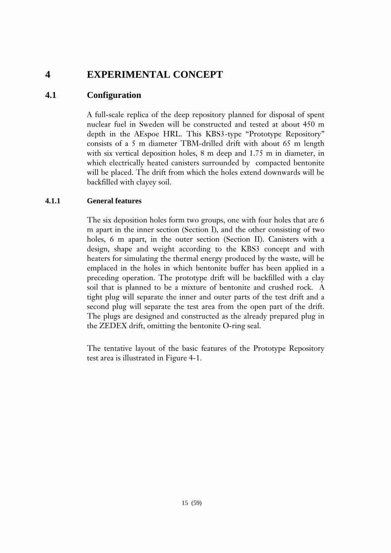
4.1.1 General features
The six deposition holes form two groups, one with four holes that are 6 m apart in the inner section (Section I), and the other consisting of two holes, 6 m apart, in the outer section (Section II). Canisters with a design, shape and weight according to the KBS3 concept and with heaters for simulating the thermal energy produced by the waste, will be emplaced in the holes in which bentonite buffer has been applied in a preceding operation. The prototype drift will be backfilled with a clay soil that is planned to be a mixture of bentonite and crushed rock. A tight plug will separate the inner and outer parts of the test drift and a second plug will separate the test area from the open part of the drift. The plugs are designed and constructed as the already prepared plug in the ZEDEX drift, omitting the bentonite O-ring seal.
The tentative layout of the basic features of the Prototype Repository test area is illustrated in Figure 4-1.
16 (59)
Figure 4-1. Schematic view of the layout of the Prototype Repository and deposition hole (not to scale).
4.1.2 Test tunnel (“Deposition tunnel”)
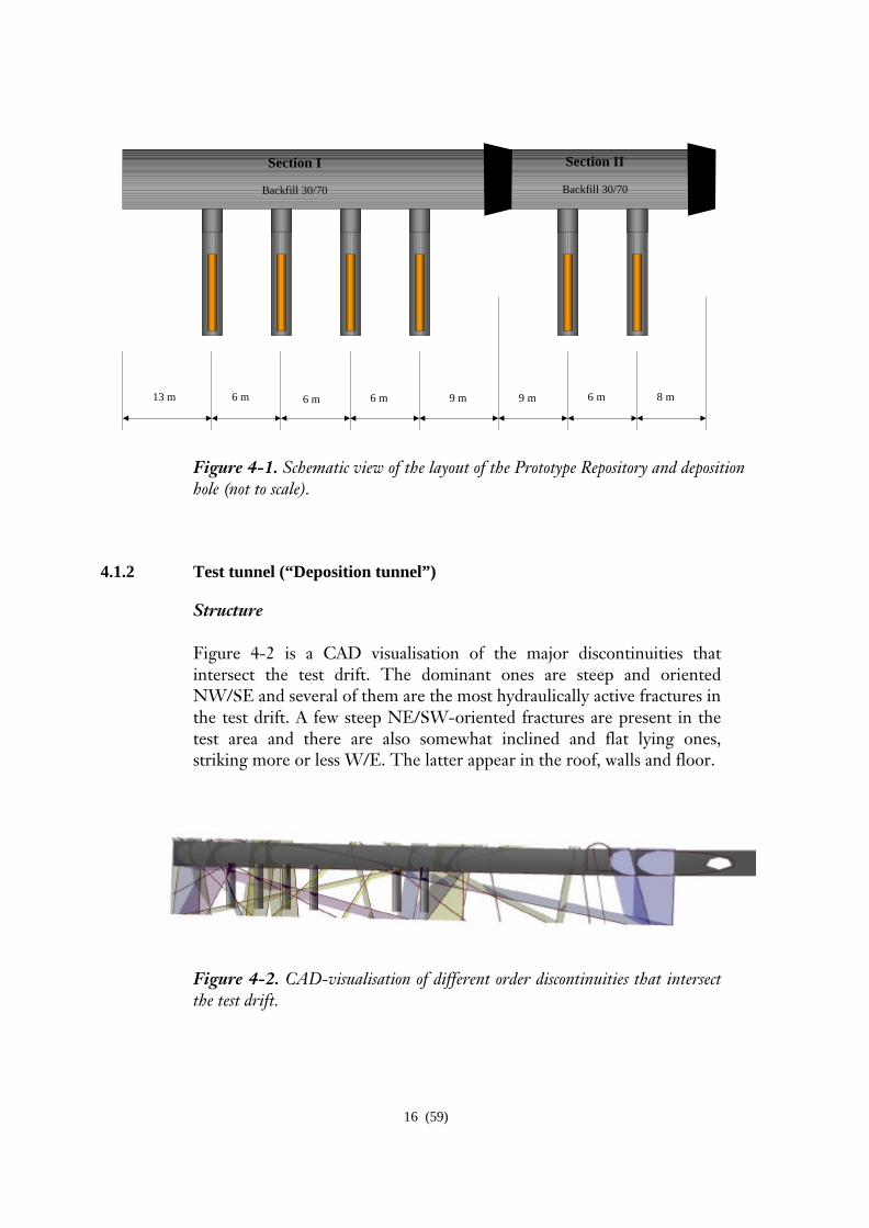
Structure Figure 4-2 is a CAD visualisation of the major discontinuities that intersect the test drift. The dominant ones are steep and oriented NW/SE and several of them are the most hydraulically active fractures in the test drift. A few steep NE/SW-oriented fractures are present in the test area and there are also somewhat inclined and flat lying ones, striking more or less W/E. The latter appear in the roof, walls and floor.
Figure 4-2. CAD-visualisation of different order discontinuities that intersect the test drift.
8 m 6 m 9 m 9 m 6 m 13 m 6 m 6 m
Section I
Backfill 30/70
Section II
Backfill 30/70
17 (59)
Rock stress conditions The drift is oriented E-W, i.e. almost perpendicular to the major principal stress. Since the hoop stress at the junction of the tunnel and the deposition holes are predicted to be on the order of 150-180 MPa [5], i.e. slightly lower than the unconfined compressive strength, the holes are expected to be stable in principle but local stress concentrations and creep may induce delayed failure. Local breakage at the upper end of the holes is in fact expected due to overloading and spalling during the heating period when the hoop stresses are expected to exceed the unconfined compressive strength [5]. At the drilling of the holes some block fall took place lower down in the holes and correlation of these spots with the rock structure models and stress calculations will be made for examination of the stability conditions and for preparation of the buffer application phase.
Hydraulic conditions
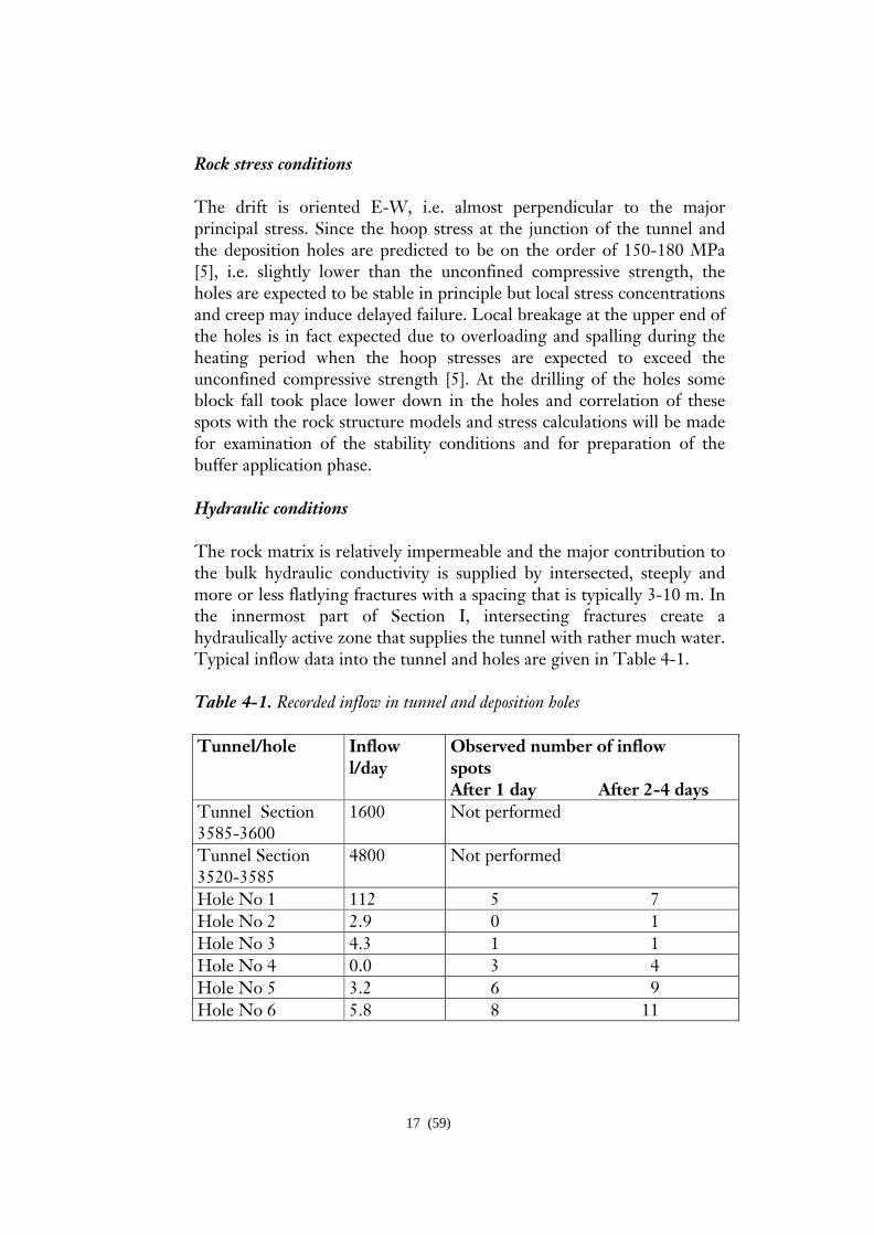
The rock matrix is relatively impermeable and the major contribution to the bulk hydraulic conductivity is supplied by intersected, steeply and more or less flatlying fractures with a spacing that is typically 3-10 m. In the innermost part of Section I, intersecting fractures create a hydraulically active zone that supplies the tunnel with rather much water. Typical inflow data into the tunnel and holes are given in Table 4-1.
Table 4-1. Recorded inflow in tunnel and deposition holes
Tunnel/hole Inflow l/day
Observed number of inflow spots After 1 day After 2-4 days
Tunnel Section 3585-3600
1600 Not performed
Tunnel Section 3520-3585
4800 Not performed
Hole No 1 112 5 7 Hole No 2 2.9 0 1 Hole No 3 4.3 1 1 Hole No 4 0.0 3 4 Hole No 5 3.2 6 9 Hole No 6 5.8 8 11
18 (59)
4.1.3 Test sections
Section I will be used for experiments under confined conditions for up to 20 years. Hence, this part of the test area will be decommissioned very late, which puts a strong demand on the selection of reliable power supply systems and long-lasting instrumentation. The latter will be less comprehensive than in the outer section.
Section II, which is separated from the inner Section I and from the rest of the drift by plugs, has two deposition holes. The rock mechanical instrumentation is concentrated to this section while the buffer and backfill instrumentation is planned to similar to the instrumentation in Section I. Decommissioning of Section II is planned to take place about 5 years after completion of the installation. At that time the buffer is expected to have been saturated, while the backfill is still believed to be incompletely saturated.
The selection of two separate sections of the test drift means that focus can be both on the early stages of the evolution of the buffer and backfill, allowing sampling rather shortly after the test start (Section II), and on processes representing later evolution stages (Section I). The exact time at which decommissioning of the innermost part will take place will be decided on the basis of the results obtained from the testing of the outer part and when data are needed for taking major decisions regarding construction of a final deep repository for high-level radioactive waste.
4.2 Buffer and backfill materials 4.2.1 Backfill
The backfill of the drift will consist of clayey soil with considerable expandability, for which a mixture of 20-30 % Na-bentonite and 70-80 % crushed rock, preferably TBM muck, is considered to be suitable [6]. The bentonite brand may be selected among natural Na-rich types or soda activated materials. According to the present plans the backfill will be applied in 0.3 m thick layers with about 35° inclination using compaction tools that were developed and tested in a separate field test. For applying the backfill, which is in granular form, the major tool is a tractor that pushes the fill to form a slope and that carries specially designed blades and vibrating plates for compacting it. This reduces the layer thickness to about 0.2 m and should give the backfill a density after water saturation of about 2000 kg/m3. The corresponding swelling
19 (59)
pressure will be at least 100 kPa when the backfill becomes fully water saturated. Where water inflow takes place at a rate that can cause piping (>0.1 l/min,m drift or even less), special measures have to be taken to avoid deterioration of the backfill, like grouting, local increase in bentonite content, or temporary discharge by use of drained permeable mats.
Chemical and mineralogical changes of the backfill will be negligible in a 20 years long test under the prevailing conditions in the AEHRL, primarily because the temperature will not be critical [7].
The study of the backfill performance will comprise determination of the density and variations in density, which control the hydraulic and compressive properties and hence water flow and hydration of the entire EBS system and thereby the upward expansion of the buffer. The time-dependent hydration and flow in the backfill will be predicted by theoretical models, the validity of which will be checked by use of test data.
4.2.2 Buffer
Before the buffer is applied in the deposition holes, the bottom of the holes will be levelled by casting a cement pad. Its hydraulic properties, which are important since it sets the hydraulic boundary conditions, will be known.
The canister-embedding clay buffer will consist of dense bentonite blocks prepared by compacting MX-80 Na-bentonite powder under 50-100 MPa pressure [8], and a filling of bentonite pellets in the 50 mm wide slot formed between the blocks and the rock. The blocks contain at least 70 % smectite and have a water content of about 17 %. The average dry density of the blocks will be 1660 kg/m3 and 1780 kg/m3 in different parts of the block pile in order to yield one and the same density after hydration and homogenisation. The initial degree of water saturation will be about 80 % for the blocks, which is achieved by wetting the air-dry powder before compaction. The annular slot between the rock and the buffer blocks will be filled with bentonite pellets (water content =10%, dry density =1900 kg/m3), while the 10 mm space between the blocks and the canisters will be left unfilled. The desired final average density of the buffer in the deposition holes after water saturation is 2000 kg/m3, yielding an average theoretical swelling pressure of about 5 MPa.
The compacted blocks have a diameter of 1.65 m and a height of about 0.5 m. A certain number of them will be solid cylinders (cheese-shape)
20 (59)
while the rest will have annular shape. The blocks will be manufactured and put on site as monoliths. Methods for quality assurance (geometry, density, strength) that have been developed in earlier projects will be applied.
The canister will rest on a cheese-shaped bentonite block and be surrounded by 10 annular ones reaching up to the top of the canister, which is covered by small brick-size blocks on which cheese-shaped blocks are applied, leaving a 1.5 m space between the uppermost block and the floor of the drift. This space will be filled with the same material as used for backfilling of the drift.
Mineralogical changes are expected to be very small in a 20 years perspective according to the current degradation model [9]. However, chemical changes in the form of exchange of adsorbed cations, slight cementation due to dissolution and precipitation of silica, and accumulation of chlorides and sulphates close to the canisters may take place.
The buffer study is of key importance to the entire experiment and is focused on practical as well as theoretical issues. The first-mentioned deal with handling and application of large buffer blocks and bentonite pellets under repository conditions, while the latter concern water saturation, expansion and heating, as well as chemical changes and gas and microbial processes. They have all been modelled and the test results will give a unique opportunity of checking the validity of models and predictions.
4.3 Canisters
The canisters, which are of BWR type, are manufactured in the Encapsulation Project undertaken by SKB in Oskarshamn [10]. They have a steel insert and an outer 30 or 50 mm thick copper liner, both alternatives are tested in the Prototype Repository. The length and diameter are 4830 and 1050 mm, respectively. The operative weight of the empty canister is approximately 21.4 tonnes for the 50 mm copper liner type. A full load of 12 BWR fuel assemblies would add about 3.6 tonnes to this weight.
The heat production of the waste – about 1800 W per canister - is simulated by use of electrical heaters in each of the channels in the steel core. They have a power of 300 W and form individual units consisting of three elements with 900 W power. All twelve channels are equipped
21 (59)
with heaters, which provides a major redundancy powerwise. Heater elements from different manufacturers are used in each canister in order to provide redundancy also with respect to technical liability. Power is supplied by three cables extending horizontally from the side of the lid of each canister.
The power is 230 V three-phase alternating current that is thyristor-controlled for automatic maintaining of the selected power level, which can be changed if desired. The system will be designed to simulate the decay process of an average canister in the Swedish program.
The heat propagation in and around a KBS-3 repository has been predicted for the constraint of not exceeding 100oC on the surface of the canister. In [11] the proposed safety margins added up to 20oC, which gave a total ceiling value of 80oC on the canister’s surface in the calculations. Each canister was defined to have a thermal initial load of 1620 W corresponding to 25 years of operation of each of the remaining Swedish nuclear power reactors. The result was three different patterns of deposition holes for the three different rock types studied in the safety project SR97. A 40-year operation time for the reactors would rather yield an average of 1700-1800 W per canister, and a calculation with 1800 W in the Prototype Repository rock and 6 m center distance between the canisters has resulted in a temperature of 85oC and 90oC respectively on the surface of the hottest canister – number three from the front – when the bentonite is assumed to saturate fairly quickly and fairly slowly respectively [12, 13]. Thermal properties of the rock have been applied in accordance with the results from the field measurements in the prototype tunnel [14]. The use of true canisters gives an opportunity to test their performance with respect to heat dissipation, and also to check their behaviour at all stages in transporting, handling and application under repository conditions although the device for emplacing the canisters in the buffer columns will be somewhat simpler than the one intended for use in a real repository. The study will give detailed information on the most important phases of the canister handling with respect to the integrity of the buffer and serve as a basis for possibly required later improvement of the emplacement tools.
4.4 Plugs
The specification of plugs in a KBS-3 repository [15] is primarily that they have to resist 4.5 MPa water pressure and an effective pressure of 100 kPa exerted by the backfill, for which a concrete plug of earlier
22 (59)
design will be used, excepting the bentonite O-ring seal. They will extend into shallow recesses extending into the surrounding rock by 1.5 m and cement grouting may be made for sealing the plug/rock contact in order to minimize leakage and drop in piezometric head in the backfilled parts. The distance between the centre of the plugs and the closest deposition hole will be about 8 m. All cables from the deposition holes will be placed in sealed boreholes that extend to a separate, parallel drift, named the “G tunnel”, where they are connected to the various recording units. Only a few tubes for gas and water sampling from the buffer and backfill are planned to be taken through the outer plug.
4.5 Instrumentation 4.5.1 General
The rock, backfill and buffer will be instrumented for recording important processes in the buffer, backfill and surrounding near-field rock. The canisters will be equipped with fibre optical cables on their surfaces for a close-pattern measurement of the temperature (T) in the copper shield. The rock around one hole in Section I will be instrumented with thermocouples (T). Some additional thermocouples are distributed along the tunnel. In section II the majority of the rock stress gauges (M), which were installed prior to boring of the deposition holes, will remain in operation also during the test, and the acoustic emission (AE) system (used in Section II) will be re-installed. A number of holes into the near-field rock will be furnished with packers for isolating different hydraulic features, where hydraulic characteristics can be measured as well as tested on-line (H). Some of the sections will also have connecting pipes for on-line water sampling (C, B). A few are planned to be furnished with combined piezometric and strain gauges for observation of combined mechanical/hydraulic processes (HM). The buffer in the two deposition holes in Section II and two of the holes in Section I (one being the same as the one surrounded by thermocouples), including the backfill overlying them, will be instrumented, while the remaining holes will be equipped with buffer and canisters but without or with sparse instrumentation. The instruments cover thermal, hydraulic and mechanical (T, H, M) sensors as well as gas and water samplers (C, B), and parcels with concrete and cellulose packages (C)
23 (59)
Gauges and sensors, some of which will be manufactured and installed by co-operating international organisations, will be used for recording the following properties and processes:
• Temperature evolution in canister, buffer, backfill and rock • Hydraulic conductivity and hydraulic head of the nearfield rock • Stresses and displacement in the nearfield rock • Coupled hydraulic and stress regimes • Wetting of buffer and backfill • Evolution of pore pressure in buffer, backfill and rock • Evolution of swelling pressure and displacement in buffer and backfill • Deformation and settlement of canisters • Gas accumulation and composition in the buffer • Chemical composition of the buffer and backfill pore waters and of
the water in the near-field rock • Salt accumulation in the buffer • Mineral alteration in the buffer • Bacterial growth and migration in the buffer. • Cellulose alteration in high pH environment
The instrumentation has been selected on the basis of comprehensive experience from previous field tests, like preceding tests in the AEHRL, the Stripa BMT experiment, and the FEBEX test, but the high-salt conditions in the AEHRL require use of low-corrosion metals like titanium in certain gauges. The data acquisition system is designed so as to provide large number of data at flexible regularity and has proved to be suitable and reliable in the various field tests preceding the Prototype Repository Project. All recorded data will be used for comparison with predicted values obtained in the various modelling activities. Hence, the measurements will yield data for setting boundaries and be used for evaluation of the performance of the buffer, backfill and near-field rock, which is the essence of the whole project.
4.5.2 T measurements on copper surface
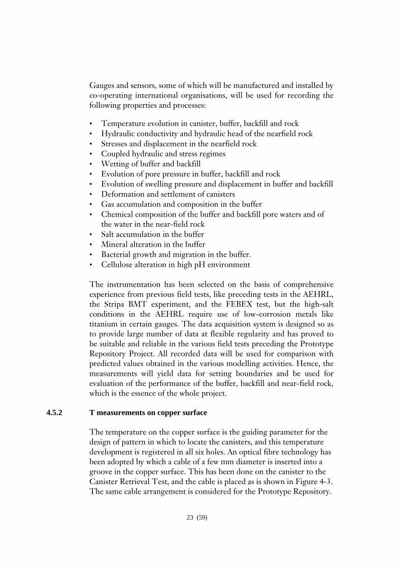
The temperature on the copper surface is the guiding parameter for the design of pattern in which to locate the canisters, and this temperature development is registered in all six holes. An optical fibre technology has been adopted by which a cable of a few mm diameter is inserted into a groove in the copper surface. This has been done on the canister to the Canister Retrieval Test, and the cable is placed as is shown in Figure 4-3. The same cable arrangement is considered for the Prototype Repository.
24 (59)
Figure 4-3. Arrangement of optical fibre cable for temperature measurement on canister surface in the Canister Retrieval Test, which will be copied in the Prototype Repository
4.5.3 THM and AE measurements in rock
Short and long holes are or have been drilled for measurement of the temperature evolution using thermocouples, and for determining rock stress changes and displacements using strain gauges. New holes for thermocouples are distributed along Section I with a concentration around deposition hole number 3. Certain holes are used for measuring the hydraulic connectivity and hydraulic conductivity of the rock. These
25 (59)
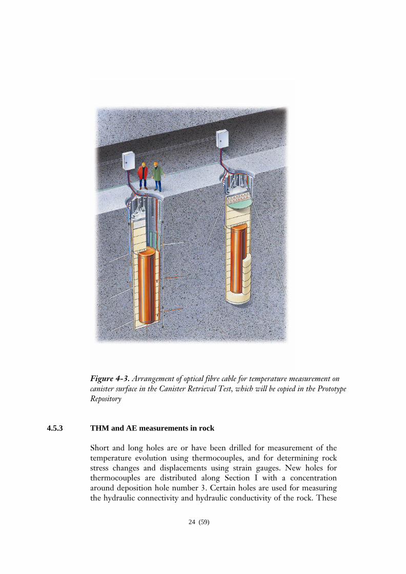
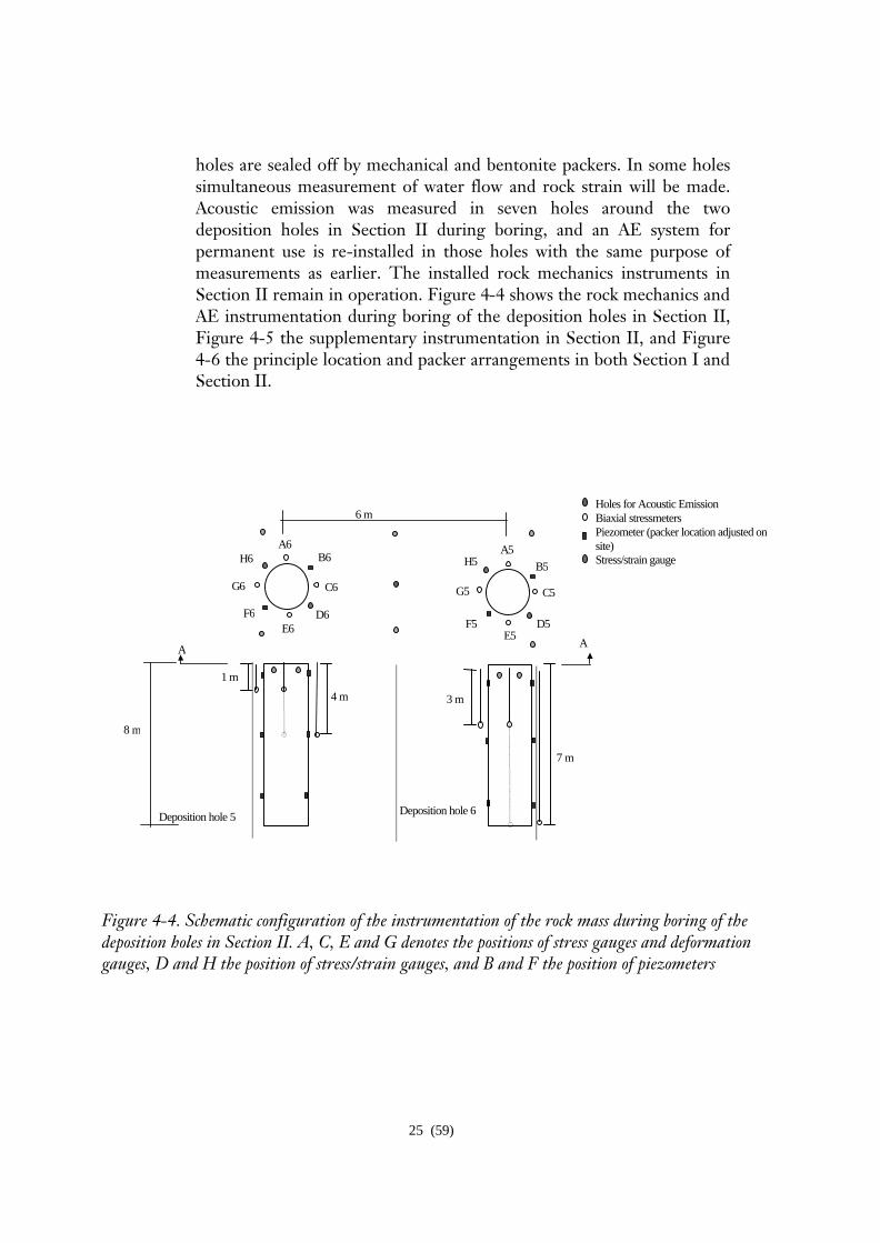
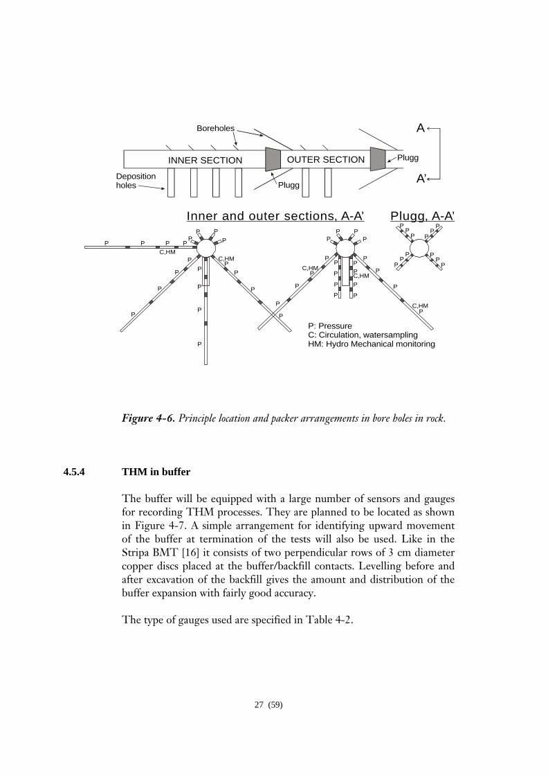
holes are sealed off by mechanical and bentonite packers. In some holes simultaneous measurement of water flow and rock strain will be made. Acoustic emission was measured in seven holes around the two deposition holes in Section II during boring, and an AE system for permanent use is re-installed in those holes with the same purpose of measurements as earlier. The installed rock mechanics instruments in Section II remain in operation. Figure 4-4 shows the rock mechanics and AE instrumentation during boring of the deposition holes in Section II, Figure 4-5 the supplementary instrumentation in Section II, and Figure 4-6 the principle location and packer arrangements in both Section I and Section II.
Figure 4-4. Schematic configuration of the instrumentation of the rock mass during boring of the deposition holes in Section II. A, C, E and G denotes the positions of stress gauges and deformation gauges, D and H the position of stress/strain gauges, and B and F the position of piezometers
Holes for Acoustic EmissionBiaxial stressmetersPiezometer (packer location adjusted onsite)Stress/strain gauge
6 m
Deposition hole 6
A
3 m
7 m
A5B5
C5
E5F5 D5
G5
H5
Deposition hole 5
A
1 m
4 m
8 m
A6B6
C6
D6E6
F6
G6
H6
26 (59)
2.20 m
2.20 m
Figure 4-5. Principle layout of boreholes for radial displacement instrumentation in Section II. Both thermocouples and deformation gauges are installed in the horizontal holes. Strain and temperature will be measured in the bottom of the deposition holes.
27 (59)
Figure 4-6. Principle location and packer arrangements in bore holes in rock.
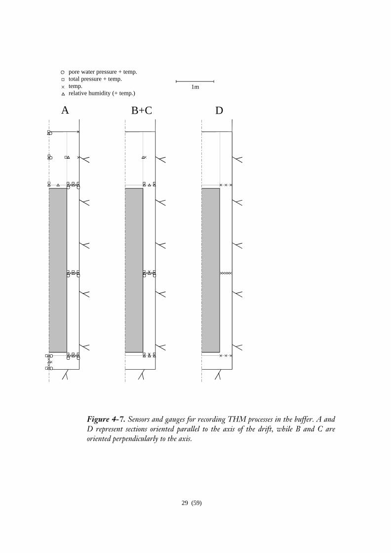
4.5.4 THM in buffer
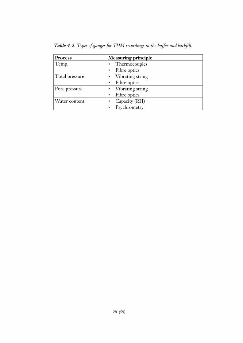
The buffer will be equipped with a large number of sensors and gauges for recording THM processes. They are planned to be located as shown in Figure 4-7. A simple arrangement for identifying upward movement of the buffer at termination of the tests will also be used. Like in the Stripa BMT [16] it consists of two perpendicular rows of 3 cm diameter copper discs placed at the buffer/backfill contacts. Levelling before and after excavation of the backfill gives the amount and distribution of the buffer expansion with fairly good accuracy. The type of gauges used are specified in Table 4-2.
INNER SECTION OUTER SECTION Plugg
Boreholes
Depositionholes Plugg
Inner and outer sections, A-A’ Plugg, A-A’
P: PressureC: Circulation, watersamplingHM: Hydro Mechanical monitoring
P
PP
P
PP P
P
P
P
P
P
C,HM
C,HM
PPP
PPPP
A’
A
C,HM
PP
P
P
P
P
P
P
C,HM
P
P
P
P
PP
PPP
P
PP
PC,HM
PP
P
P
P
P
P
P
P
P
P
P
28 (59)
Table 4-2. Types of gauges for THM recordings in the buffer and backfill. Process Measuring principle Temp. • Thermocouples
• Fibre optics Total pressure • Vibrating string
• Fibre optics Pore pressure • Vibrating string
• Fibre optics Water content • Capacity (RH)
• Psychrometry
29 (59)
pore water pressure + temp.total pressure + temp.temp.relative humidity (+ temp.)
A B+C D
1m
Figure 4-7. Sensors and gauges for recording THM processes in the buffer. A and D represent sections oriented parallel to the axis of the drift, while B and C are oriented perpendicularly to the axis.
30 (59)
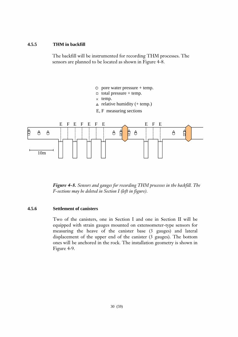
4.5.5 THM in backfill The backfill will be instrumented for recording THM processes. The sensors are planned to be located as shown in Figure 4-8.
10m
pore water pressure + temp.total pressure + temp.temp.relative humidity (+ temp.)
E F E EF F E E F E
E, F measuring sections
Figure 4-8. Sensors and gauges for recording THM processes in the backfill. The F-sections may be deleted in Section I (left in figure).
4.5.6 Settlement of canisters
Two of the canisters, one in Section I and one in Section II will be equipped with strain gauges mounted on extensometer-type sensors for measuring the heave of the canister base (3 gauges) and lateral displacement of the upper end of the canister (3 gauges). The bottom ones will be anchored in the rock. The installation geometry is shown in Figure 4-9.
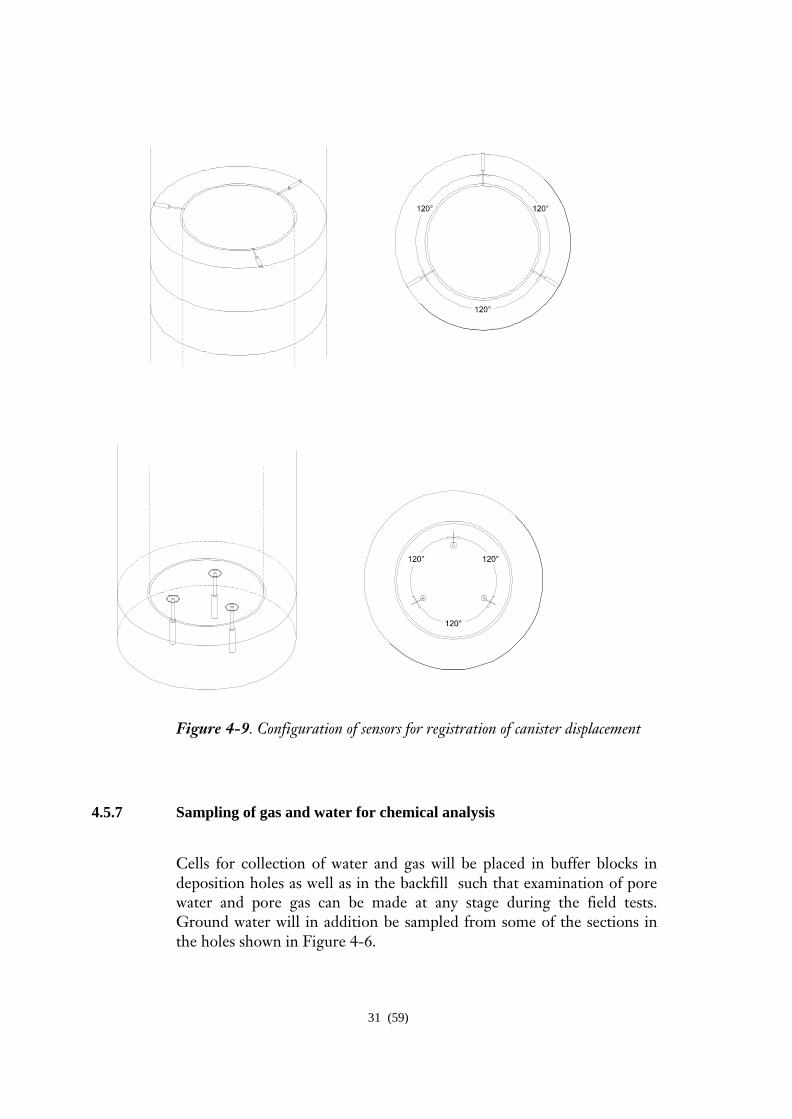
31 (59)
Figure 4-9. Configuration of sensors for registration of canister displacement 4.5.7 Sampling of gas and water for chemical analysis
Cells for collection of water and gas will be placed in buffer blocks in deposition holes as well as in the backfill such that examination of pore water and pore gas can be made at any stage during the field tests. Ground water will in addition be sampled from some of the sections in the holes shown in Figure 4-6.
32 (59)
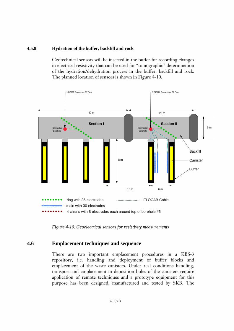
4.5.8 Hydration of the buffer, backfill and rock
Geotechnical sensors will be inserted in the buffer for recording changes in electrical resistivity that can be used for “tomographic” determination of the hydration/dehydration process in the buffer, backfill and rock. The planned location of sensors is shown in Figure 4-10.
18 m 6 m
40 m 25 m
5 m
ring with 36 electrodes
chain with 30 electrodes
4 chains with 8 electrodes each around top of borehole #5
8 m
Backfill
Canister
Buffer
Section I Section IIConnection Borehole
Connection Borehole
1 GISMA Connector, 37 Pins 5 GISMA Connectors, 37 Pins
ELOCAB Cable
Figure 4-10. Geoelectrical sensors for resistivity measurements
4.6 Emplacement techniques and sequence
There are two important emplacement procedures in a KBS-3 repository, i.e. handling and deployment of buffer blocks and emplacement of the waste canisters. Under real conditions handling, transport and emplacement in deposition holes of the canisters require application of remote techniques and a prototype equipment for this purpose has been designed, manufactured and tested by SKB. The
33 (59)
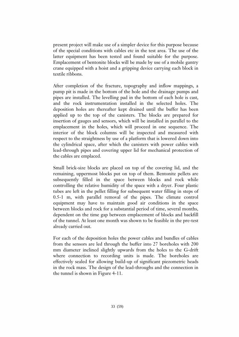
present project will make use of a simpler device for this purpose because of the special conditions with cables etc in the test area. The use of the latter equipment has been tested and found suitable for the purpose. Emplacement of bentonite blocks will be made by use of a mobile gantry crane equipped with a hoist and a gripping device carrying each block in textile ribbons. After completion of the fracture, topography and inflow mappings, a pump pit is made in the bottom of the hole and the drainage pumps and pipes are installed. The levelling pad in the bottom of each hole is cast, and the rock instrumentation installed in the selected holes. The deposition holes are thereafter kept drained until the buffer has been applied up to the top of the canisters. The blocks are prepared for insertion of gauges and sensors, which will be installed in parallel to the emplacement in the holes, which will proceed in one sequence. The interior of the block columns will be inspected and measured with respect to the straightness by use of a platform that is lowered down into the cylindrical space, after which the canisters with power cables with lead-through pipes and covering upper lid for mechanical protection of the cables are emplaced.
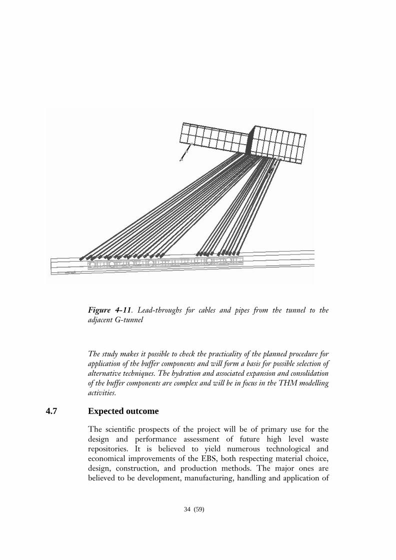
Small brick-size blocks are placed on top of the covering lid, and the remaining, uppermost blocks put on top of them. Bentonite pellets are subsequently filled in the space between blocks and rock while controlling the relative humidity of the space with a dryer. Four plastic tubes are left in the pellet filling for subsequent water filling in steps of 0.5-1 m, with parallel removal of the pipes. The climate control equipment may have to maintain good air conditions in the space between blocks and rock for a substantial period of time, several months, dependent on the time gap between emplacement of blocks and backfill of the tunnel. At least one month was shown to be feasible in the pre-test already carried out. For each of the deposition holes the power cables and bundles of cables from the sensors are led through the buffer into 27 boreholes with 200 mm diameter inclined slightly upwards from the holes to the G-drift where connection to recording units is made. The boreholes are effectively sealed for allowing build-up of significant piezometric heads in the rock mass. The design of the lead-throughs and the connection in the tunnel is shown in Figure 4-11.
34 (59)
Figure 4-11. Lead-throughs for cables and pipes from the tunnel to the adjacent G-tunnel
The study makes it possible to check the practicality of the planned procedure for application of the buffer components and will form a basis for possible selection of alternative techniques. The hydration and associated expansion and consolidation of the buffer components are complex and will be in focus in the THM modelling activities.
4.7 Expected outcome
The scientific prospects of the project will be of primary use for the design and performance assessment of future high level waste repositories. It is believed to yield numerous technological and economical improvements of the EBS, both respecting material choice, design, construction, and production methods. The major ones are believed to be development, manufacturing, handling and application of
35 (59)
clay materials for embedding waste containers and backfilling of tunnels, and development of equipments and techniques for homogeneous backfilling of tunnels.
Major expectations are firstly that the technical feasibility and practicality of geological disposal will be demonstrated, and secondly that an improved basis for safety assessment will be achieved by the deepened understanding of the integrated engineered barrier systems/rock performance. A third expectation is that the project will provide information and assistance to researchers involved in an international cluster of organisations engaged in developing safe repositories.
4.8 Problem areas
The most essential components of the test arrangement are the heaters since breakdown or malfunctioning, or loss of electric power over longer periods of time will ruin major parts of the project. Redundance and back-up of the heating units and the instruments have been secured in the design and manufacturing but there is no guarantee that these parts of the engineered system will perform problem-free throughout tests that are pursued beyond 5-10 years.
Difficulties may arise in the practical construction and instrumentation activities and in the development and application of theoretical models. Problems may appear in the handling and application of buffer components in the deposition holes, like difficulties in accurate positioning of the heavy buffer blocks and uniform filling of bentonite pellets, but they are not expected to jeopardise the entire application procedure. Some delay must be expected, however, and this may cause problems by in-flowing water in certain phases. For minimising such problems and for offering training opportunities the first deposition hole to be filled should be one with very little water inflow. However, special reasons may lead to other successions.
Backfilling of the drift has been trained in a separate field test and is not believed to cause problems, except for the very important case when there is strong water inflow. This may make it impossible to pursue the operation and underlines the necessity of significantly reducing the present inflow by grouting or other means. Since several other conditions make the Prototype Repository test drift deviate from those of a true repository, like the fact that no effective pre-grouting could be made, a safe way of avoiding water-related problems with the backfill application is to apply drains over local areas where much water flows
36 (59)
from the rock and connect them to a pipe that extends to the outer end of the respective test section. The pipe can be sealed with cement or clay grout after closing the test area.
As to difficulties in describing the performance of the EBS, already available coupled THM models are believed to be sufficiently useful for predicting and evaluating thermally induced water saturation/de-saturation processes and mechanical strain. However, the setting of hydraulic boundary conditions and establishing the hydraulic interaction between buffer and rock are still problematic issues although information from earlier studies, like the Stripa BMT experiment [17] and ongoing as well as forthcoming supplementary studies are expected to be helpful in this task. Chemical and biological modelling is believed to be much more difficult and a primary aim is to develop conceptual models that can later be put in mathematical form, at least as concerns chemical processes (THMC).
37 (59)
5 SCOPE
5.1 Main project tasks
The major tasks are
• Application and instrumentation of EBS components and construction of a representative part of a KBS-3 repository including plugs
• Performance of heating tests under controlled thermal conditions • Modelling plan • Scoping calculations • Data collection • Predictive calculation of coupled and uncoupled processes using
theoretical models • Evaluation of data from recordings • Comparison of predictions and actual data • Evaluation of the project
5.2 Preparation of test arrangement and performance of tests
These activities have been described in detail under Chapter 4 “Experimental concept”.
5.3 Modelling plan
5.3.1 General
A number of the rock features and processes and the evolution of the buffer and backfill will be modelled. A major distinction can be made between on the one hand modelling of the structural constitution of the rock including changes in structure due to stress alterations caused by excavation and thermal effects, and on the other hand modelling of the evolution of the buffer and backfill, i.e. the two EBS components of primary interest in the project.
5.3.2 Rock structure modelling
The regional rock in the AEHRL area has been described and modelled with respect to structure, petrology and groundwater conditions and the near field rock of the test drift is being characterised in detail with
38 (59)
respect to the rock structure constitution. This work will yield numerical 3D models consisting of discontinuities of different orders [15] and channels formed by their intersections. These models will be used for flow calculation and coupled and uncoupled rock mechanical analyses.
5.3.3 Modelling of EBS evolution
Modelling of important processes will be performed in two steps; 1) by use of simple models for scoping calculations, which have partly been made, and 2) by use or development of complete coupled thermo-hydro-mechanical (THMC) models of the near-field rock and buffer and backfill for predicting heat and water transport with due respect to changes in mechanical stresses and transient chemical processes. Since the aim is to adjust the temperature evolution to fit the radioactive decay in a true repository, the electric power must be controlled, for which a model is being developed. Modelling of long-term chemical changes in the buffer, backfill and contacting rock will be made in separate studies, which will also comprise modelling of microbiological processes.
The EBS modelling is of particular interest to several of the international groups that are involved in the project. Thus, the representatives of ENRESA, GRS, BGR, UWC will co-operate in development of conceptual and theoretical modelling of a number of processes in the buffer and rock, primarily THM including hydration, swelling/consolidation, and gas penetration. The various attempts are indicated later in this chapter and in the Work Package specifications in Chapter 6.
5.4 Scoping calculations
Scoping calculations have been made by SKB for preliminary prediction of the thermal evolution and for selection of the required density and initial degree of water saturation of the buffer and backfill, as well as for selecting suitable positions of the instruments in the EBS and near-field rock. These estimates have indicated the approximate rate of water saturation of the clay materials under assumed boundary conditions and will be used for deciding the time for decommissioning. More refined predictions are under way, using rock structure models that are presently being developed.
5.5 Data collection
39 (59)
5.5.1 Measurements
Measurements will be made by use of the various gauges installed in the rock, buffer and backfill. Recording will be made by use of data acquisition systems with a regularity that will be adapted to predicted and recorded rates of the respective processes. The very comprehensive number of raw data makes it difficult to overview the experiments and identify trends, and great effort is therefore made in developing or improving numerical codes for visualisation of individual and coupled processes. Major processes will be plotted with short time intervals so that the responsible scientific staff can currently overview and evaluate them.
5.5.2 Data
The most important information that is required for modelling the performance of the EBS and near field rock concerns heat and water transport in the buffer and near-field rock, which depend on the piezometric conditions in the rock. The evolution of these processes will be manifested by numerous data provided by the various acquisition systems. Also, data from the stress and strain instrumentation in the buffer and backfill as well as in the near-field rock will be of significant importance and form a considerable part of the recordings. Sampling and analysis of gas and electrolytes in the buffer are essential but the tests will probably only yield few data. The investigation of microbes can not be made until decommissioning has taken place and separate recording methods will be applied for this purpose.
Water uptake, degree of water saturation
The rate of water uptake of the initially incompletely saturated buffer and backfill is essential since it controls the temperature evolution and the internal strain generated in the course of moistening, as well as chemical processes like salt accumulation. Direct measurement of the hydration/dehydration processes will be made by use of RH-sensors installed in the buffer. The principle is that suction is produced in the buffer and backfill until complete water saturation is reached, the change in water content being measured by use of psychrometers. Resistivity measurements have the same purpose (cf. Table 2, Section 4.5.4).
Temperature
40 (59)
Temperature is the driving force of a number of physical and chemical processes in the buffer, backfill and near-field rock. Comprehensive monitoring and recording is therefore required and a large number of thermal gauges will be installed. The canisters will on the surface be equipped with a fibre optic cable for temperature measurements.
Water pressure
The water pressure in the rock, buffer and backfill will increase gradually and the natural piezometric pressure conditions will be re-established after a long time. This state will not be reached in the testing period due to the draining function of a number of major water-bearing fractures at various distances from the drift but high pressures are expected rather soon in Section I. They affect the rate of water saturation of the rock, backfill and buffer and need to be known for prediction and evaluation of this rate and for controlling that the design of the plugs is appropriate. A considerable number of piezometers will therefore be installed in buffer, backfill and rock.
Gas accumulation and composition
Pore gas, primarily produced by the decreasing air volume in the voids during saturation and by thermally aided processes, will be sampled in the buffer and backfill (cf. Section 4.5.7). Gas migration is planned to be identified in buffer samples extracted after termination of the tests by use of techniques for microstructural analysis. Total pressure
The total pressure, i.e. the sum of the effective or swelling pressure and the pore water pressure in the buffer and backfill and at the contact between the rock and the buffer, and also at the contact between the walls of the drift and the backfill, will be measured by use of earth pressure cells. Since the water pressure is recorded separately using the piezometers, the swelling pressure can be evaluated.
Displacements and strain measurements
In the operation phase, wetting and heating of the buffer will produce strain. The increase in temperature will exert thermo-mechanical loading of the host rock, buffer and canisters and thereby yield strain. Swelling pressure in the buffer, particularly uneven build-up of pressures, may displace the canisters and produce mechanical loading of the walls of the
41 (59)
deposition holes. Pressures and strain will be recorded by use of the instrumentation described earlier in this document.
Shear displacement may take place along certain major fractures that intersect the deposition holes. Attempts are made to record such displacements by use of strain gauges installed in series in radially oriented boreholes extending from the deposition holes.
Vertical displacement (uplift or settlement) of the canisters will be measured (cf. Section 4.5.6).
Groundwater chemistry
Sampling of groundwater for chemical analysis has been made in the rock characterisation phase and will continue in the operation phase. The analyses will be performed by use of mass spectrometry and X-ray fluorescence according to AEHRL classes 2, 3 and 4, with reference to AEHRL standard [1].
Mineral alteration
Very small changes in the smectite content are expected in the up to 20 years long test period according to current geochemical models. However, certain accessory minerals in the buffer, like carbonates, feldspars, sulphides and sulphates will undergo substantial changes, affecting the porewater chemistry and some of them causing precipitation in the hot part of the buffers. The mineral changes will be identified by X-ray diffraction and transmission electron microscopy as well as by determining the cation exchange capacity of specimens sampled after extraction of the buffers.
Microbiology
Microbiological processes in the form of survival, multiplication and migration of bacteria, primarily sulphate-reducing species, will be investigated using methods applied in comprehensive preceding laboratory tests. Analyses will be performed in the operation and excavation phases.
Sampling
Many physical, chemical and biological processes can not be recorded by instruments and gauges but require analysis of extracted samples.
42 (59)
However, sampling in the operation phase affects the integrity of the buffer, backfill and rock and makes it necessary to restore these media by replacing the material removed. Certain sampling operations, like extraction of small amounts of water and gas for subsequent laboratory analysis can be made without disturbance and such operations are planned (cf. Section 4.5.7). Through this, ion migration paths and rates can be evaluated by using tracer techniques. Micro- and macro-structural changes and precipitation of dissolved and migrated inorganic matter may also be detected in the operation phase but most of the processes have to be determined by examining samples after termination of the tests.
5.5.3 Data base
The large amount of information on material and instrument data obtained in conjunction with planning, operation and evaluation of the field test will make it possible to establish a comprehensive EBS data base that will be of use in future studies of repository performance and monitoring of a forthcoming KBS-3 repository. It is included in the AEHRL site data base (SICADA).
5.6 Predictive calculations
1. Calculation of the required transient heater powering will be made by use of the FEM-code ANSYS
2. Rock mechanical calculations for predicting strain in the nearfield
rock and identifying possibly existing unstable rock (overstressing) will be made. Several programs including 3D finite element code and boundary element code will be considered for this purpose
3. Prediction of hydraulic conditions in the test site area as well as
around the deposition drift and holes will be made by use of DFN modelling
4. Attempts will be made to predict the behaviour of the complete
Prototype Repository system, i.e. the integrated function of the near-field rock, buffer and backfill, by coupled THM analyses using several different codes. Examples of such calculations with ABAQUS have been published [3] and they demonstrate the necessity of using accurate hydraulic boundary conditions for wetting of the buffer. Thus, the calculations imply that complete hydration will take 5 years for unlimited access to water at the rock/buffer interface, while it will
43 (59)
take considerably more than 30 years if the water pressure is low and water is given off only from a few fractures.
The theoretical predictions will be currently compared with results evolving from the Prototype Repository tests during operation. Successive upgrading of the models will be made.
5.7 Evaluation of data and validation of models
The data provided by the acquisition systems or obtained by using separate recording units will be plotted with suitable time intervals and currently compared with the predictions. There will be up-to-date diagrams plotted on all major processes with current comparison with the predictions. This is particularly important for making sure that the heater system works properly and yields canister temperatures corresponding to those caused by the radioactive decay of the waste in a true repository.
The data manifesting the evolution of temperature and pressure are very accurate and current interpretation is a straight forward matter as concluded from preceding field experiments, primarily the Stripa BMT project, while evaluation of other processes like canister motion and displacements in the rock, buffer and backfill is expected to be more difficult. This is also the case for physico/chemical processes in the rock, buffer and backfill and for all of them the time required for evaluation and assessment may be considerable. In some cases upgrading of the theoretical models may have to be made in parallel to the experiments and it is foreseen that the accuracy in describing many of the processes may be fairly low. Relevant modelling of the physical processes in the buffer close to the canisters can not be made until supporting laboratory tests have been performed in order to define and describe the macro- and micro-structural evolution in the drying part of the buffer. Hence, application of coupled THM models must be made with care and due respect to the structural constitution. The same is valid for chemical and microbial processes and complete THMCB models probably have to be relatively simple.
Once complete sets of data from the monitoring become available they will be compared with the predicted ones and the validity of the respective models evaluated. These activities, which will include upgrading of the models, are expected to be largely completed at the termination of the experiments.
44 (59)
5.8 Safety issues
Safety is related to risks for human beings, i.e. the staff on site and intermittently present scientists and technicians, and for possible mishaps in the preparative work on site, or for malfunctioning of test components and power and monitoring systems. The first-mentioned issue is of general character and considered by the SKB organisation, which has the overall responsibility of the AEHRL. For the test and monitoring systems the following matters.
Despite the careful planning of the Prototype Repository field experiments some of the tests may not be possible or will yield quite different and unexpected results that affect the testing procedure or time schedule. The experience from earlier successful large-scale field tests like the Stripa BMT project gives very good confidence in the present project but the conditions are somewhat different from these experiments and may cause problems:
• The inflow of water into the test drift may be substantially higher
than what can be accepted in a real repository and may require drainage during the application of the buffer and backfill. This arrangement must be designed so that the piezometric conditions can develop in a natural fashion after completing the plug constructions.
• The pore water pressure in the backfill will be high and may cause
difficulties with electrical systems and leakage into the buffer along cable bundles, by which the boundary conditions set for calculation of water uptake of the buffer may not be valid.
• The high salt content of the groundwater will cause corrosion of
ordinary gauges and sensors and titanium has therefore been selected as a suitable lasting metal for the manufacturing. It is necessary to make sure that there are no iron objects in the buffer and backfill because they will produce hydrogen gas that can have an effect on the water saturation and generate electric potentials. Great care must also be taken to avoid damage yielding exposure of reinforcement bars in the plugs.
• Breakdown of the data acquisition system with loss of all or large
parts of stored data might take place. Regular, frequent saving and storage of data at AEspoe will minimise the risk of loosing information.
45 (59)
• The heater elements in the canisters may break down requiring rearrangement of the power connections, which is possible because of the sufficient number of elements. Different types of heaters will be installed so that a systematic error in one type will not affect the overall performance of the heater system. Moisture migration into the canisters is prevented by using the most efficient and proven connections for lead-throughs in the lid.
While these problems are foreseen and countermeasures already taken, there are others that may be more problematic and have to be considered:
• Short-circuit of the power system in the test arrangements behind the
concrete plugs will largely damage the project. This problem can be partly avoided by careful testing of the various power transmission components before closure but unexpected large strain in the buffer due to its expansion upwards in the deposition holes may cause breakage of cables for power supply and for transfer of output signals from the gauges. The design of the system must therefore include estimation of possible extreme buffer strain, which has been made preliminarily.
• Large instantaneous rock deformations shortly after backfilling and
plugging due to heat-generated stress accumulation in the rock can affect the buffer and canisters. It may cause changes in rock/buffer interaction and difficulties in interpreting the tests, and also power breakdown by cable damage. Predictive rock mechanical calculations will be of some assistance in determining whether critical conditions should be expected. This is still to be done.
• Early breakdown of gauges and sensors due to failing cable
connections or malfunctioning. Back-up by installing parallel systems of different types of gauges (cf. Table 2, Section 4.5.4) can reduce this problem but it can still not be guaranteed that the majority of the recording instruments survive the long-term experiment in Section I. This would mean that information on the physical and chemical states of the buffer and backfill can only be obtained by examining samples after at the termination of the test, while transient processes will not be known.
If any of the last mentioned events takes place one has to consider terminating the project prior to the planned dates. However, detailed
46 (59)
plans will be worked out for avoiding mishaps of the types mentioned and for saving maximum information in case of breakdown of gauges and power.
5.9 Supporting project tasks 5.9.1 General
A number of supporting investigations on laboratory and bench scales will be performed. They are integrated in the field experiments but require more defined boundary conditions for relevant evaluation. Such tests will concern:
• Hydrochemistry of granitic groundwaters • Removal of oxygen from HLW by bacteria and through rock-water
reactions • Hydraulic conductivity of the disturbed zone caused by TBM boring • Changes in porewater chemistry of the buffer • Structural changes in the buffer, particularly in the canister-near part
where temporary desiccation will make the clay fracture, which affects subsequent hydration and homogenisation. Also, the interaction of buffer blocks and pellets will be investigated with respect to structure and physical behaviour to find out whether heterogeneities remain after hydration
• Structural changes in the buffer close to the rock in the maturation phase comprising gel formation and consolidation may yield anisotropic constitution
• The chemical composition of the water initially adsorbed by the buffer is different from that of water given off by the near-field rock, which may cause changes in clay microstructure and thereby altered swelling and conductivity properties
• Colloid migration in buffer material and rock fractures • Gas migration in buffer material and rock fractures
5.9.2 Specific studies
Hydraulic conductivity of the boring-disturbed zone A number of samples with a diameter of around 100 mm have been cored from different parts of the rock wall in some of the deposition holes. These samples will be examined by methods using He-gas and 14CPMMA (carbon 14 polymethylemethaneacrylate) for identification of
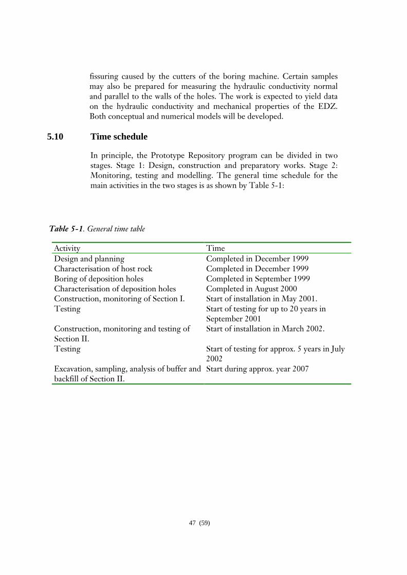
47 (59)
fissuring caused by the cutters of the boring machine. Certain samples may also be prepared for measuring the hydraulic conductivity normal and parallel to the walls of the holes. The work is expected to yield data on the hydraulic conductivity and mechanical properties of the EDZ. Both conceptual and numerical models will be developed.
5.10 Time schedule
In principle, the Prototype Repository program can be divided in two stages. Stage 1: Design, construction and preparatory works. Stage 2: Monitoring, testing and modelling. The general time schedule for the main activities in the two stages is as shown by Table 5-1:
Table 5-1. General time table
Activity Time Design and planning Completed in December 1999 Characterisation of host rock Completed in December 1999 Boring of deposition holes Completed in September 1999 Characterisation of deposition holes Completed in August 2000 Construction, monitoring of Section I. Start of installation in May 2001. Testing Start of testing for up to 20 years in
September 2001 Construction, monitoring and testing of Section II.
Start of installation in March 2002.
Testing Start of testing for approx. 5 years in July 2002
Excavation, sampling, analysis of buffer and backfill of Section II.
Start during approx. year 2007

48 (59)
6 PROJECT ORGANISATION
6.1 General
The Prototype Repository Project will be performed and reported following the guidelines given in the Project Plan, which is the project´s quality document [18]. This implies application of scientific principles and regular reporting at meetings on several levels and current documentation in various report series.
Participants in the international co-operation are:
Name of organisation Acronym Country
Swedish Nuclear Fuel and Waste SKB Sweden
Management Co Posiva OY Posiva Finland Empresa Nacional de Residuous ENRESA Spain radioactivos S.A.
Gesellschaft fuer Anlagen- und GRS Germany
Reaktorsicherheit Bundesanstaly fuer Geowissenschaften BGR Germany Und Rohstoffe Geoenvironmental Research Center UWC UK University of Cardiff Japan Nuclear Cycle Development JNC Japan Institute
Assistant contractors Asociacion para la Investigacion AITEMIN Spain y Desarollo Industrial de la Recurcos Naturales Centre Internacionale de Metode CIMNE Spain Numerics en Enginyeria Clay Technology AB CLAY Sweden VBB/VIAK AB VBB Sweden Geodevelopment AB GEO Sweden VTT Communities and Infrastructure VTT Finland

49 (59)
6.2 Organisation 6.2.1 General
A Project Manager is in charge of the project and is assisted by the project staff. A Steering Committee and a Work Package Group is established for governing the EC project work, which will be headed and co-ordinated by SKB. The Parties will have to review their own work in the respective work packages and put together and report relevant material in the prescribed way. The Steering Committee summons meetings and seminars and reviews draft reports.
6.2.2 Organisation of work
All activities will be grouped into Work Packages. WP0 below is no part of the EC project as this work has started and is in an advanced state of progress. The outcome of the work, however, is a prerequisite for conducting the subsequent WPs in the EC project :
WP0. Design and construction of canister with heaters, bentonite blocks, backfilling and plugs (engineered barrier systems, EBS).
WP1. Design of instrumentation and manufacturing of sensors.
WP2. Emplacement of bentonite buffer, disposal of canisters with heaters, backfilling of tunnel and construction of plugs.
WP3. Conceptual modelling of the function of EBS and application and development of mathematical models for describing important EBS processes and integrated EBS performance.
Each work package specifies activities that are merged into larger groups in several steps. The main structure of this hierarchy appears in Appendix A. .
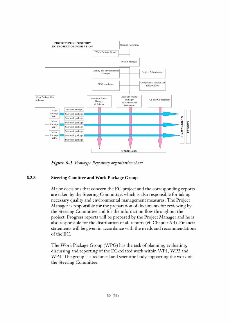
50 (59)
Project Manager
Occupational Health and Safety Officer
Assistant Project Manager
of Science
On Site Co-ordinator
EC Co-ordinator
Work Package Group
Work Package
WP1
Work Package
WP2
Work Package
WP3 DE
LIV
ER
AB
LE
S
SITEWORKS
Steering CommitteePROTOTYPE REPOSITORY
EC PROJECT ORGANISATION
RE
PO
RT
S
Assistant Project Manager
of Methods and Techniques
Project AdministratorQuality and Environmental
Manager
Sub work package
Sub work package
Sub work package
Sub work package
Sub work package
Sub work package
Sub work package
Sub work package
Work Package Co-ordinator
Figure 6-1. Prototype Repository organisation chart
6.2.3 Steering Comittee and Work Package Group
Major decisions that concern the EC project and the corresponding reports are taken by the Steering Committee, which is also responsible for taking necessary quality and environmental management measures. The Project Manager is responsible for the preparation of documents for reviewing by the Steering Committee and for the information flow throughout the project. Progress reports will be prepared by the Project Manager and he is also responsible for the distribution of all reports (cf. Chapter 6.4). Financial statements will be given in accordance with the needs and recommendations of the EC. The Work Package Group (WPG) has the task of planning, evaluating, discussing and reporting of the EC-related work within WP1, WP2 and WP3. The group is a technical and scientific body supporting the work of the Steering Committee.

51 (59)
6.2.4 On-Site Staff
The project will be organised in accordance with the guidelines given in the Project Plan, see the organisation chart in Figure 6-1. The Project Manager for the Prototype Repository is Christer Svemar, SKB, who also will responsible for EC co-ordination. He will be assisted by Lars-Olof Dahlström, NCC Teknik, who will act as Assistant Project Manager for Science in the project and Gunnar Ramqvist, SKB, who will act as Assistant Project Manager for Methods and Techniques. Activities in the Prototype Project will mainly be co-ordinated and organised by personnel at AEHRL and by participants with responsibilities within projects related to engineered barriers at AEHRL. The On-site Co-ordinator for the project is Christer Andersson, SKB. Roland Pusch will serve as secretary of the Steering Committee, and supervise the interaction of theoretical technical issues in the EC project as well as manage technical reporting. Christer Svemar will act as Chair of the Steering Committee and Peder Thorsager will act as Chair of the Work Package Group.
6.3 Data management
Data collected during characterisation and preparation will be filed in the AEHRL site data base (SICADA). The data will be accompanied with a description of how it is collected and formatted. Task leaders are responsible for handling and quality assurance of all data. The responsibility of filing and storing data rests with the Data Manager at AEHRL, Ebbe Eriksson.
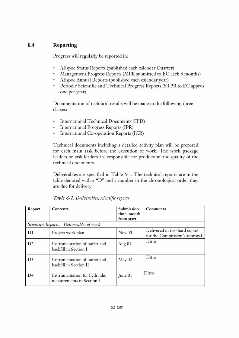
52 (59)
6.4 Reporting
Progress will regularly be reported in: • AEspoe Status Reports (published each calendar Quarter) • Management Progress Reports (MPR submitted to EC each 6 months) • AEspoe Annual Reports (published each calendar year) • Periodic Scientific and Technical Progress Reports (STPR to EC approx
one per year)
Documentation of technical results will be made in the following three classes:
• International Technical Documents (ITD) • International Progress Reports (IPR) • International Co-operation Reports (ICR)
Technical documents including a detailed activity plan will be prepared for each main task before the execution of work. The work package leaders or task leaders are responsible for production and quality of the technical documents.
Deliverables are specified in Table 6-1. The technical reports are in the table denoted with a “D” and a number in the chronological order they are due for delivery. Table 6-1. Deliverables, scientific reports
Report Contents Submission
time, month from start
Comments
Scientific Reports – Deliverables of work
D1 Project work plan Nov 00 Delivered in two hard copies for the Commission´s approval
D2 Instrumentation of buffer and backfill in Section I
Aug 01 Ditto
D3 Instrumentation of buffer and backfill in Section II
May 02 Ditto
D4 Instrumentation for hydraulic measurements in Section I
June 01 Ditto Ditto
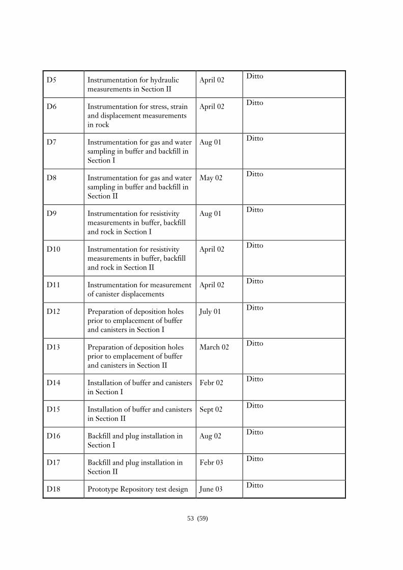
53 (59)
D5 Instrumentation for hydraulic measurements in Section II
April 02 Ditto
D6 Instrumentation for stress, strain and displacement measurements in rock
April 02 Ditto
D7 Instrumentation for gas and water sampling in buffer and backfill in Section I
Aug 01 Ditto
D8 Instrumentation for gas and water sampling in buffer and backfill in Section II
May 02 Ditto
D9 Instrumentation for resistivity measurements in buffer, backfill and rock in Section I
Aug 01 Ditto
D10 Instrumentation for resistivity measurements in buffer, backfill and rock in Section II
April 02 Ditto
D11 Instrumentation for measurement of canister displacements
April 02 Ditto
D12 Preparation of deposition holes prior to emplacement of buffer and canisters in Section I
July 01 Ditto
D13 Preparation of deposition holes prior to emplacement of buffer and canisters in Section II
March 02 Ditto
D14 Installation of buffer and canisters in Section I
Febr 02 Ditto
D15 Installation of buffer and canisters in Section II
Sept 02 Ditto
D16 Backfill and plug installation in Section I
Aug 02 Ditto
D17 Backfill and plug installation in Section II
Febr 03 Ditto
D18 Prototype Repository test design June 03 Ditto
54 (59)
and installation
D19 Sensor data report #1 March 02 Ditto
D20 Sensor data report #2 Sept 02 Ditto
D21 Sensor data report #3 March 03 Ditto
D22 Sensor data report #4 Sept 03 Ditto
D23 Sensor data report #5 Febr 04 Ditto
D24 Water and gas analysis report #1 Dec 02 Ditto
D25 Water and gas analysis report #2 Sept 03 Ditto
D26 Water and gas analysis report #3 Febr 04 Ditto
D27 Hydraulic test results Aug 01 Ditto
D28 THM laboratory tests on buffer and backfill – progress report #1
Jan 03 Ditto
D29 THM laboratory tests on buffer and backfill – progress report #2
Febr 04 Ditto
D30 THM laboratory tests on rock– progress report #1
March 03 Ditto
D31 THM laboratory tests on rock– progress report #2
Febr 04 Ditto
D32 Determination of porosity in EDZ
Aug 02 Ditto
D33 Selection of THMCB models May 01 Ditto
D34 Predictive THMCB modelling of buffer, backfill and rock
June 02 Ditto
D35 Comparison of results from THMCB modelling of buffer, backfill and rock, with measured data from Prototype Repository
Aug 03 Ditto
D36 Final Report on EC Project Febr 04 Ditto

55 (59)
The final report will be prepared in close co-operation of the Work Package Leaders, the Project Manager and the secretary of the Steering Commitee.
The final report will preliminarily be organised as follows:
1. General, description of test site 2. Description of Project Plan
3. Description of construction, instrumentation, test procedure, experience
gained and conclusions on practical results
4. Predictions of THMCB processes, description of models
5. Results of measurements concerning THMCB
6. Evaluation of results. Relevance, validity and accuracy of conceptual and theoretical models
7. Discussion and conclusions. Practical value of the project.
8. Recommendations for further work
9. Summary
56 (59)
7 REFERENCES
1. Dahlstroem L-O, 1998. Test Plan for the Prototype Repository. SKB AEHRL Progress Report HRL-98-24, Stockholm.
2. Ljunggren C, Bergsten Rock stress measurements in KA3579G. SKB
AEHRL Progress Report HRL-98-09, Stockholm.
3. Boergesson L, Hernelind J, 1999. Coupled thermo-hydro-mechanical calculations of the water saturation phase of a KBS-3 deposition hole. SKB Technical Report TR-99-41, Stockholm.
4. Boergesson L, Hernelind J, 2000. Preliminary modelling of the water
saturation phase of the buffer and backfill materials. SKB AEHRL International Progress Report IPR-00-11, SKB, Stockholm
5. Zeng L, Dahlstroem L-O, 1999. Finite Element Analyses of
mechanical consequences due to the rock excavation and thermal load. SKB AEHRL International Progress Report IPR 99-16, Stockholm.
6. Pusch R 1995. Consequences of using crushed crystalline rock as
ballast in KBS-3 tunnels instead of rounded quartz particles.SKB Technical Report TR 95-14, Stockholm.
7. Pusch R, Takase H, 1998. Chemical processes causing cementation
in heat-affected smectite – the Kinnekulle case. SKB Technical Report TR-98-25, Stockholm.
8. Johannesson L-E, 1999-66. Compaction of full size blocks of
bentonite for the KBS-3 concept. SKB Report R-99-66, Stockholm.
9. Pusch R, 1993. Evolution of models for conversion of smectite to non-expandable minerals. SKB Technical Report TR 93-33, Stockholm.
10. Werme L, 1998. Design premises for canister for spent nuclear fuel.
SKB Technical Report TR 98-08, Stockholm.
11. Ageskog L, Jansson P, 1999. Heat propagation in and around the deep repository. SKB Technical Report TR-99-02, SKB, Stockholm.
57 (59)
12. Ageskog L, Jansson P, 1998. Prototype Repository – Finite element analyses of heat transfer and temperature distribution in buffer and rock, general part & Case No. 1. SKB AEHRL Progress Report HRL-98-20, Stockholm.
13. Jansson P, Koukkanen M, 1999. Prototype Repository – Finite
element analyses of heat transfer and temperature distribution in buffer and rock, Case No. 2. SKB AEHRL International Progress Report IPR-01-07, Stockholm
14. Sundberg J, Gabrielsson Field measurements of thermal properties of
the rocks in the prototype repository at AEHRL. SKB AEHRL International Progress Report IPR-99-17, Stockholm.
15. SKB, 1999. SR 97, Waste, repository design and sites, SKB
Technical Report TR-99-08, Stockholm.
16. Pusch R, Nilsson J, Ramqvist G, 1985. Final Report of the Buffer Mass Test – Volume I: scope, preparative field work, and test arrangement. Stripa Project Technical Report 85-11, Stockholm.
17. Pusch R, Boergesson L, Ramqvist G, 1985. Final Report of the
Buffer Mass Test – Volume II:test results. Stripa Project Technical Report 85-12, Stockholm.
18. Persson G, Broman O, 2000. Prototype Repository. Project Plan
version 1.01 – EC Contract FIKW-CT-2000-00055. SKB AEHRL International Progress Report IPR-00-31, Stockholm.
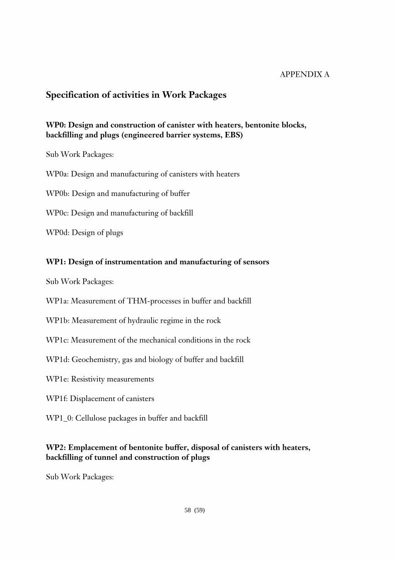
58 (59)
APPENDIX A
Specification of activities in Work Packages WP0: Design and construction of canister with heaters, bentonite blocks, backfilling and plugs (engineered barrier systems, EBS) Sub Work Packages: WP0a: Design and manufacturing of canisters with heaters WP0b: Design and manufacturing of buffer WP0c: Design and manufacturing of backfill WP0d: Design of plugs WP1: Design of instrumentation and manufacturing of sensors Sub Work Packages: WP1a: Measurement of THM-processes in buffer and backfill WP1b: Measurement of hydraulic regime in the rock WP1c: Measurement of the mechanical conditions in the rock WP1d: Geochemistry, gas and biology of buffer and backfill WP1e: Resistivity measurements WP1f: Displacement of canisters WP1_0: Cellulose packages in buffer and backfill WP2: Emplacement of bentonite buffer, disposal of canisters with heaters, backfilling of tunnel and construction of plugs Sub Work Packages:
59 (59)
WP2_0: Lead-throughs to the G-tunnel WP2a:Preparation of holes and installation of sensors WP2b: Emplacement of buffer and disposal of canisters WP2c: Emplacement of backfill WP2_00: Construction of plugs WP3: Conceptual modelling of the function of EBS and application and development of mathematical models for describing important EBS processes and integrated EBS performance Sub Work Packages: WP3_0: Supervision and data management WP3a: Water and gas sampling and analysis WP3b: Hydraulic tests in rock WP3c: THM laboratory tests on buffer and backfill properties: WP3d: Laboratory tests on mechanical properties of rock and THM processes in rock WP3e: Laboratory determination of cracks in EDZ WP3f: T and TM modelling WP3g: HM and THM modelling of the rock mass WP3h: THM modelling of buffer, backfill and interaction with near-field rock WP3i: C modelling of buffer, backfill and groundwater Each Sub Work Package consists of different Tasks that details the work of each Sub Work Package. Each Task consists of Activities, for which Activity Plans are compiled in accordance to the quality system as described in the Project Plan /18/