afb manual as rs s7 a003
TRANSCRIPT

AFB Manual
Station AS/RS

2 © Festo Didactic GmbH & CoKG. • AFB
This document consists of 4 parts, divided into:
• Part A contains the manual of the system or station. • Part B, as far as present, contains a collection of exercises together with relevant
solutions or additional information. • Part C contains the circuit diagram of the system or station. • Part D contains the data sheets of the system or station.
Order no.:
Name: Manual AS/RS
Designation: AFB_Manual_AS_RS_S7_A003
Date: 11.12.2007
Author: Schober
Graphics: Schober
Layout: Schober
© Festo Didactic GmbH & Co., D-73770 Denkendorf, 2007
Internet: www.festo.com/didactic
e-mail: [email protected]
This manual, all text and illustrations included, is protected by copyright. Any utilization outside the
limits of the copyright law and other than training purposes are not permissible without our definite
approval. This applies in particular to reproductions, operations, translations, micro filming and the
storing and processing into electronic systems. Parts of this manual may be copied by the authorized
user, exclusively for teaching purposes. Distribution of this documentation, as well as reproduction,
use and spread of its contents is prohibited, insofar not permitted explicitly. Offences are liable to
compensation. All rights reserved, especially the right to execute registrations concerning patents,
designs for use and patterns.

Intended use
© Festo Didactic GmbH & Co.KG. • AFB 3
Intended use
This installation was developed and manufactured for use in basic and further training in the fields of automation and communications. The training company and/or the training staff must ensure that the trainees observe the safety precautions described in the accompanying manuals. Furthermore this manual describes setup and possible uses of the singular stations. It contains all information and data required for commissioning, maintenance and operation.
Festo Didactic accepts no liability for injury or harm to trainees, the training company and/or any third parties occurring when the installation is used for any purpose apart from training, except Festo Didactic has caused such injury or harm intentionally or by grossly negligence.

Intended use
4 © Festo Didactic GmbH & CoKG. • AFB

Content
© Festo Didactic GmbH & Co.KG. • AFB 5
Content
1 Introduction ______________________________________________________ 9
1.1 General Information AFB ________________________________________ 9
1.2 AS/RS station _______________________________________________ 10
1.2.1 Topics for project work ____________________________________ 12
1.3 Duty of the operating authority _________________________________ 13
1.4 Duty of trainees ______________________________________________ 13
1.5 Warranty and liability _________________________________________ 14
1.6 Intended use ________________________________________________ 15
1.7 Important notes ______________________________________________ 15
2 General safety instructions _________________________________________ 17
2.1 Handling the system __________________________________________ 17
2.1.1 Dangers in handling the machine ____________________________ 17
2.1.2 Safety precautions in standard operation _____________________ 18
2.1.3 Dangers due to electric current _____________________________ 18
2.1.4 Dangers due to pneumatic energy ___________________________ 19
2.1.5 Maintenance – Servicing – Malfunction removal ________________ 19
2.1.6 Organizational measures __________________________________ 19
2.2 Personnel ___________________________________________________ 20
2.2.1 Notes on personnel _______________________________________ 20
2.2.2 Training operations _______________________________________ 20

Content
6 © Festo Didactic GmbH & CoKG. • AFB
2.2.3 Outside training operations ________________________________ 20
2.3 Emergency stop system _______________________________________ 20
2.3.1 Safety symbols __________________________________________ 21
3 Commissioning __________________________________________________ 23
3.1 Transport ___________________________________________________ 23
3.1.1 Unpacking ______________________________________________ 23
3.1.2 Scope of delivery _________________________________________ 23
3.2 Set up ______________________________________________________ 24
3.2.1 General information ______________________________________ 24
3.3 Commissioning ______________________________________________ 27
3.3.1 Pneumatical commissioning ________________________________ 27
3.3.2 Electrical commissioning __________________________________ 27
3.3.3 Communication cables ____________________________________ 28
3.3.4 EMERGENCY-STOP system _________________________________ 29
3.4 Start-up process _____________________________________________ 33
4 Operation _______________________________________________________ 35
4.1 General notes on operation ____________________________________ 35
4.1.1 Handling regulations ______________________________________ 35
4.1.2 Operating regulations _____________________________________ 35
4.2 Touch panel AS/RS station _____________________________________ 36
4.2.1 Menu Touch Panel ________________________________________ 37
4.3 Reset ______________________________________________________ 43

Content
© Festo Didactic GmbH & Co.KG. • AFB 7
4.3.1 Requirements ___________________________________________ 43
4.3.2 Adjustment process_______________________________________ 43
4.4 Automatic mode _____________________________________________ 43
4.4.1 Requirements and start automatic mode ______________________ 43
4.4.2 Stop automatic __________________________________________ 43
4.5 Process description ___________________________________________ 44
4.6 Material flow ________________________________________________ 45
5 Technology _____________________________________________________ 47
5.1 drawings ___________________________________________________ 47
5.2 Technical datas ______________________________________________ 48
6 Pneumatic ______________________________________________________ 49
6.1 The valve ___________________________________________________ 49
6.2 Pneumatic cylinder ___________________________________________ 50
6.3 Pneumatic supply ____________________________________________ 51
7 Electrical system _________________________________________________ 53
7.1 Power supply ________________________________________________ 53
7.2 Controller ___________________________________________________ 54
7.2.1 Controller design S7 ______________________________________ 54
7.3 Wiring ______________________________________________________ 55
7.3.1 I/O-Components _________________________________________ 55
7.4 Axis with CAN-BUS ___________________________________________ 57
7.4.1 Function CAN-BUS ________________________________________ 58

Content
8 © Festo Didactic GmbH & CoKG. • AFB

© Festo Didactic GmbH & Co.KG. • AFB 9
The Festo Didactic Learning System for Automation and Technology is designed to meet a number of different training and vocational requirements. The systems and stations of the AFB facilitate industry-orientated vocational and further training. The hardware consists of didactically suitable industrial components.
The stations provides an appropriate system for practice-orientated tuition of the following key qualifications
• Social competence, • Technical competence and • Methodological competence
Moreover, training can be provided to instill team spirit, willingness to cooperate and organizational skills.
Actual project phases can be taught by means of training projects, such as:
• Planning, • Assembly, • Programming, • Commissioning, • Operation, • Maintenance and • Fault finding.
This manual describes the handling of the AFB system. It contains explanations and descriptions of all the processes required for operation. Facts are partly described with the help of graphics or images sub serving an easier understanding.
Complete operating instructions which explain the processes of the system are available for working with the system. Additionally to technical and social competence, the comprehension of the process and the interaction of the respective components appear in clear presentation. Festo Didactic succeeded in using the most updated industrial hard- and software for this model production.
The AFB system is a successively expandable system consisting of individual stations. However, the central unit is always the transport system. For this reason, this manual is not only a general manual, but also a station manual for the transport system. Each one of the other stations has its own manual.
Operation is not dependant on the operating position the material flow is being started from. Still, the sequential order of the stations requires adherence, as it is pre-defined in the PLC-program.
1 Introduction
1.1 General Information AFB

Introduction
10 © Festo Didactic GmbH & CoKG. • AFB
The AFB system is designed in such a way, that the amount and kind of attached stations guaranteed is not important. A complete processing cycle of the work-piece is always warranted. Only the transport system is required under any circumstances.
If the automatic mode is started, the filling station is starting to work. Bottles are filled with liquid and a cover is placed and turned on the bottle to close it. The filled bottles are transported to the packing station. Here 6 bottles are grouped. As soon as these are 6 bottles, an empty six pack is ordered and equipped with the waiting bottles. First one line with 3 bottles and then the second line with 3 bottles.
The filled tray is transported to the In/Out station for handing out of the system. If the handing out slide at the In/Out station is occupied, the trays are carried into the AS/RS station for intern storage. As soon as the handing out slide at In/Out station is free, the six packs are restored from the AS/RS and are carried on the slides of the In/Out station.
In case the In/Out station is not available or not active all filled six packs are stored in the AS/RS.
The AS/RS is responsible to store and restore the trays.
The carrier arriving on the transport system, stops in front of the AS/RS station. The tray on the carrier is gripped from the AS/RS handling and moved to one of the free shelve. The status of the tray (full or empty) is transmitted to the controller. Afterwards the carrier is released.
If an empty tray is requested from another station, a carrier is ordered to the AS/RS. If the carrier is ready, an empty tray is picked out from one of the shelve and is placed on the waiting carrier. Afterwards the carrier is released and transported to the waiting station.
1.2 AS/RS station

Introduction
© Festo Didactic GmbH & Co.KG. • AFB 11
Overview In/Out station
Position Description Position Description
1 CAN-Motor x-axis 6 Reception for workpiece trays
2 Axis for x-motion 7 Tray to pick up 6 workpieces
3 CAN-Motor z-axis 8 Touch panel for operation
4 Axis for z-motion 9 Shelf to pick up one tray
5 Pneumatic axis for y-motion

Introduction
12 © Festo Didactic GmbH & CoKG. • AFB
Training contents covering the following subjects can be taught:
• Mechanics – Mechanical construction of a station
• Pneumatics – Piping connections of pneumatic components – Pneumatic linear drives
• Electrical – Correct wiring of electrical components – Use of electric axes
• Sensors – Correct use of limit switches
• PLC – Programming and use of a PLC – Structure of a PLC program
• Commissioning – Commissioning of a production system
• Fault finding – Systematic fault finding on a production system
• CAN-Bus technology – Programming and use of CAN-Bus
1.2.1 Topics for project work
• Replacing a relay control system with a PLC • Selecting pneumatic components
– Linear drives • PLC programming
– Programming of an operational section – Programming of a RESET sequence – Programming of an EMERGENCY-STOP function
• Optimising cycle time

Introduction
© Festo Didactic GmbH & Co.KG. • AFB 13
The operating authority undertakes to ensure that the AFB is used only by persons who:
• are familiar with the basic regulations regarding operational safety and accident prevention and who have received instructions in the handling of the AFB,
• have read and understood the chapter on safety and the cautionary notes in this manual.
• Safety-conscious working of the persons should be regularly vetted.
Prior to commencing work, all persons assigned to working on the MPS® have a duty to:
• read the chapter on safety and the cautionary notes in this manual and, • observe the basic regulations regarding operational safety and the prevention of
accidents.
1.3 Duty of the operating authority
1.4 Duty of trainees

Introduction
14 © Festo Didactic GmbH & CoKG. • AFB
In principle all our „Terms and Conditions of Sale“ apply. These are available to the operating authority upon conclusion of the contract at the latest. Warranty and liability claims for persons or material damage are excluded if these can be traced back to one or several of the following causes:
• Use of the AFB not in accordance with its intended purpose • Incorrect assembly, commissioning, operation and maintenance of the AFB • Operation of the AFB using faulty safety equipment or incorrectly fitted or non
operational safety or protective devices
• Non observance of notes in the manual regarding transport, storage, assembly, commissioning, operation, maintenance and setting up of the AFB
• Unlawful constructional modifications on the AFB • Inadequate monitoring of components subject to wear • Incorrectly carried out repairs • Catastrophes as a result of foreign bodies and vis major.
Festo Didactic herewith rules out any liability for damage or injury to trainees, the training company and/or other third parties which may occur during the use/operation of the system other than purely in a training situation, unless such damage has been caused intentionally or due to gross negligence by Festo Didactic.
1.5 Warranty and liability

Introduction
© Festo Didactic GmbH & Co.KG. • AFB 15
This installation was developed and manufactured only for use in basic and further training in the fields of automation and communications. The training company and/or the training staff must ensure that the trainees observe the safety precautions described in the accompanying manuals. Furthermore this manual describes setup and possible uses of the singular stations. It contains all information and data required for commissioning, maintenance and operation.
Festo Didactic accepts no liability for injury or harm to trainees, the training company and/or any third parties occurring when the installation is used for any purpose apart from training, except Festo Didactic has caused such injury or harm intentionally or by grossly negligence.
The use of the system for its intended purpose also includes:
• Following all advice in the manual and • Carrying out inspection and maintenance work.
The basic requirement for safe use and trouble-free operation of the AFB is to observe the fundamental safety recommendations and regulations.
This manual contains important notes concerning the safe operation of the AFB.
The safety recommendations in particular must be observed by anyone working on the AFB.
Furthermore, the rules and regulations for the prevention of accidents applicable to the place of use must be observed.
1.6 Intended use
1.7 Important notes

Introduction
16 © Festo Didactic GmbH & CoKG. • AFB
© Festo Didactic GmbH & Co.KG. • AFB 17
2.1.1 Dangers in handling the machine
The installation has been constructed technologically up to date and in conformance with the recognized rules of safety engineering. Nevertheless, during operation it is possible that harm might be caused to the user or third parties or that the installation or other property might get damaged. Therefore, the installation has to be handled according to specified operational use in perfect technical condition only.
Safety endangering malfunctions cannot be tolerated during training and have to be removed immediately.
The AFB is to be used only:
• for its intended purpose and • in absolutely safe conditions.
Faults impairing safety must be rectified immediately!
2 General safety instructions
2.1 Handling the system

General safety instructions
18 © Festo Didactic GmbH & CoKG. • AFB
2.1.2 Safety precautions in standard operation
Put the installation into operation only, once all of the protection settings are completely functional.
At least, before starting operation, check the installation for externally visible damages and for the reliability of the safety devices.
Do not grip into the installation while in operation.
Before circuit construction, circuit disassembly and circuit modification: switch off air pressure and power supply.
General safety regulations are to be observed: DIN 58126 and VDE 0100.
2.1.3 Dangers due to electric current
As soon as maintenance is completed, check the function reliability of the safety devices.
Only trained experts in electric or electronic engineering are permitted to carry out work on the electric supply system.
The terminal boxes are to be kept closed at all times. Access must be permitted only under supervision of a member of the training staff.
Do not activate electric limit switches manually during fault search. Tools are to be used.
Only low voltage 24VDC is to be used.

General safety instructions
© Festo Didactic GmbH & Co.KG. • AFB 19
2.1.4 Dangers due to pneumatic energy
Accidents might occur due to bouncing off tubes, caused by air pressure. Interrupt air pressure supply immediately.
Caution! When the air pressure supply is activated, cylinders may move in or out.
Do not uncouple any tubes under air pressure supply. Exception: Fault finding. In this case, keep on holding the end of the tube.
Do not exceed the permitted operating pressure. See data sheets.
2.1.5 Maintenance – Servicing – Malfunction removal
Carry out adjustments and inspections as instructed, in accordance with the specified intervals.
Secure the compressed air and electricity supplies to prevent unintentional start-up.
During inspections, maintenance and repair work, the machine must be de-energized, de-pressurized and secured against unexpected restart.
All screw connections released during maintenance, inspection or repair work must be checked to ensure correct re-tightening.
2.1.6 Organizational measures
All existing safety devices must be checked at regular intervals.

General safety instructions
20 © Festo Didactic GmbH & CoKG. • AFB
2.2.1 Notes on personnel
Basically two situations have to be considered, concerning matters on personnel.
• Activities during training operations • Activities outside training operations
2.2.2 Training operations
Trainees are permitted to work with the machine only under strict supervision of an experienced person or an instructor.
Activities of trouble-shooting and fault correction are to be checked by the instructor. Special care should be taken regarding safety aspects.
2.2.3 Outside training operations
Activities in the areas of maintenance, service and repair are to be carried out by only persons with appropriate technical qualifications.
The emergency stop system is controlled by a higher safety control unit. The description is noted in the manual of the transport system.
2.2 Personnel
2.3 Emergency stop system

General safety instructions
© Festo Didactic GmbH & Co.KG. • AFB 21
2.3.1 Safety symbols
In this manual the following danger designations and signs are being used:
This symbol indicates an immediate threat to a person’s health or life.
DANGER !
Failure to pay attention to this symbol may result in serious health damage, which may even lead to life-threatening injuries.
This symbol emphasizes important information for correct machine handling.
IMPORTANT
Failure to pay attention to this symbol may result in damages to the machine or to its surroundings.
This symbol indicates operational tips and especially useful directions. i
INFORMATION
This symbol assists you to make optimal use of all of your machine’s functions.

General safety instructions
22 © Festo Didactic GmbH & CoKG. • AFB

© Festo Didactic GmbH & Co.KG. • AFB 23
Care is to be taken that the transport of the stations is to be executed only by a suitable transport vehicle. The weight amounts up to 500 kg, depending on the station.
The route of transport is to be cleared in advance, to be accessible to the transport vehicle. Installation of warning signs or barriers may be required.
The transport boxes are to be opened with care, as additional components, such as computers may be contained in the delivery, which are to be protected from falling out.
Once the transport box has been opened and the possibly contained additional components removed, the station can be taken out to be transported to its destination by means of two fork-lifts or one fork-lift truck.
Please check the stability of all of the profile connectors by means of an Allen key size 6. The connectors may have come loose during transport, due to inevitable vibration.
Pay special attention to all overhanging components. Sensors and similar small parts are very easily damaged in case of improper transport.
The stations are not to be picked up by or even under the mounted feet – increased risk of becoming trapped or contused.
Check the station for any possible damaged once unpacked. The carrier and Festo Didactic are to be notified immediately of any damage.
3.1.1 Unpacking
Carefully remove the padding material in the container box when unpacking the station. When unpacking the station, make sure that none of the station assemblies have been damaged.
Check the station for any possible damaged once unpacked. The carrier and Festo Didactic are to be notified immediately of any damage.
3.1.2 Scope of delivery
Check the scope of delivery against the delivery note and the order. Festo Didactic must be notified immediately of any discrepancies.
3 Commissioning
3.1 Transport
i

Commissioning
24 © Festo Didactic GmbH & CoKG. • AFB
3.2.1 General information
The installation is to be set up in a frost-free room with maximum relative air humidity of 70%.
In countries with an atmospheric humidity over 70% and temperatures above 25 degrees Celsius are the premises to provide an air-conditioning system for constant surroundings conditions.
To comply with the regulatory guidelines, sources of electrical interference such as welding plants, large motors and contactors are to be checked for electromagnetic compatibility in advance and screened where necessary.
To ensure fault-free operation a load-bearing floor is required to avoid settling.
Allow sufficient distance between the installation and the wall of the room.
Any dust originating from construction work has to be kept off the installation (by covering).
First, the room has to be measured, if not done so previously. The measures of all stations have to be marked roughly onto the floor space (i.e. with adhesive tape) to avoid shifting at a later stage.
3.2 Set up

Commissioning
© Festo Didactic GmbH & Co.KG. • AFB 25
The following picture shows a complete set-up situation adapted to a more basic area design. The stations are to be adjusted as shown, to ensure faultless work-piece transfer flow.
Set-up situation AFB system – the MPS-PA-Stations serves as an example

Commissioning
26 © Festo Didactic GmbH & CoKG. • AFB
Dimensional drawing of set-up AFB system

Commissioning
© Festo Didactic GmbH & Co.KG. • AFB 27
Commissioning of the system can ensue only, once all of the stations are connected to their definite position.
The AS/RS station has to be mounted at the transport system, utilising the included profiles. Align the station by means of a spirit-level and tighten the connector profiles afterwards.
3.3.1 Pneumatical commissioning
The mechanical construction must be finished. At the beginning the stations have to be attached to the pneumatic system of the room. In most cases the maintenance unit is on the profile plate of the station. The coupling has a 5 mm nominal diameter. If the available system is equipped with 7.9 mm nominal diameter, it is possible to change the coupling of the maintenance unit with a greater one. (reducer 1/8 on 1/4 necessary). If this has been carried out, the stations can be provided with 6 bar and the pneumatic commissioning is realized.
3.3.2 Electrical commissioning
First place the electrical board and the 24V powers supply unit into the station.
The station must be provided with electrical voltage now. The basic rack is provided with a power supply unit, provided with a voltage of 110/230 V. The delivered cable has a completely protected norm plug, this must be plugged into an electrical socket protected sufficiently. Distribution strips are, enclosed to this also for the connection of other stations. If an extension for the cable is necessary for the distribution strip, this can to be executed only by a trained expert. The electrical socket must be protected, corresponding to the customer.
The power supply (24 VDC) of the sensoric and the actuators of the station is provided in each case by means of a 2-pin cable. The voltage supply is a 24 V power supply unit, contained in the control cabinet or somewhere in the station.
To avoid problems during the operational process, individual protection (16A) of the installation is recommended.
3.3 Commissioning
Commissioning
28 © Festo Didactic GmbH & CoKG. • AFB
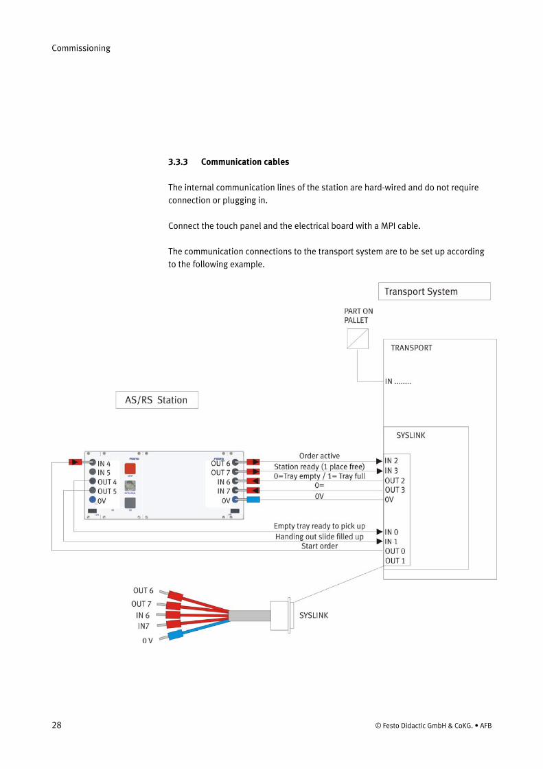
3.3.3 Communication cables
The internal communication lines of the station are hard-wired and do not require connection or plugging in.
Connect the touch panel and the electrical board with a MPI cable.
The communication connections to the transport system are to be set up according to the following example.

Commissioning
© Festo Didactic GmbH & Co.KG. • AFB 29
3.3.4 EMERGENCY-STOP system
The emergency-stop system is to be de-activated for transport. The connector possibilities are listed below and are to be re-activated during start-up. The complete emergency-stop system is described in the chapter “EMERGENCY-STOP”.
EMERGENCY-STOP connectors in control cabinet / conveyor belt
Example EMERGENCY-STOP connector on board

Commissioning
30 © Festo Didactic GmbH & CoKG. • AFB
All of the required EMERGENCY-STOP connectors can be established according to this example.
Plugs with links are to be inserted into the unoccupied operating positions, as shown in the picture above.
Plug Type Device Example
XNA11
2-pin Phönix
2 Contacts for
EMERGENCY-
STOP switch
External
EMERGENCY-STOP
switch
from XNA11 to external EMERGENGY-STOP
XNA01
4-pin Phönix
2 Contacts for
EMERGENCY-
STOP,
2 Contacts for
feedback
e.g. Testing station
from XNA01 at the conveyor belt to SPS-board
See also chapter EMERGENCY-STOP.
i

Commissioning
© Festo Didactic GmbH & Co.KG. • AFB 31
The EMERGENCY-STOP system is controlled centrally by the transport system station. In the control cabinet of the station an EMERGENCY-STOP switch device is located, which is connected to all of the operating positions and all external EMERGENCY-STOP devices.
Example: external EMERGENCY-STOP Transport system
The external EMERGENCY-STOP devices are controlled by a 2-pin cable. The devices are connected to the 2-pin Phönix plug-in contact. In case no device is plugged in, the contact is to be established with a strapped plug.
The PLC-boards are connected to the 4-pin plug-in contacts. In this case 2 lines are for the feedback (station available) and 2 lines for the EMERGENCY-STOP of the PLC-board.
EMERGENCY-STOP at the PLC-board

Commissioning
32 © Festo Didactic GmbH & CoKG. • AFB
S11 S12 S12 S21 S22
A1 B1 13 23 33 43
S33 S34 Y1 Y2 S52
53 63 73 81 91
S11 13 23 33
A1 Y1 Y2
14 24 34 44 54 64 74 82 /B2 A2 43 55 A2
Y30 Y31 Y32 Y35 Y1 14 24 34S37
PowerCH. 1 IN
START
CH. 2 IN
CH. 1 OUTCH. 2 OUT
PilzPNOZ X9
14
13
24
23
34
33
44
43
54
53
64
63
74
73
82
81
92
91
CH. 2
CH. 1
14 24 34 44
13 23 33 43
-XNA11 1
-XN111
2
2-XNA12 1
-XN121
2
2
Phönix plug -in2pin
Phönix plug-in2pin
XNA13 ==> XNA18 Other external emergency-stop devices
Emergency-Stop push button
e.G. Testing station e.G. Transportsystem
-XNA1
1
-XN1
1
22
33
44
Phönix plug-in4 pin
-XNA2
1
-XN2
1
22
33
44
Phönix plug-in4 pin
-XNA3
1
-XN3
1
22
33
44
Phönix plug-in4 pin
XNA4 =
=> XN
A10other stations
External Emergency-Stop
Emer
genc
y-st
op s
witc
h de
vice
Tr
ansp
orts
yste
m
SimaticS7-300
RUN-PRUN
STOPMRES
STOPRUNFRCEDC 5VBAFSFCPU 314
SIEMENS
12
34
5
67
89
X1MPI
43210
765
43210
765
SM323DI8/DO8 xDC24V
X 23 4
CP 342-2Asi Master
X 23 4
AUPCERAPFRUNSF
20+30+
CM
43210
765
10+
SET
Operatingposition 1
Operatingposition 2
Operatingposition 3
SimaticS7-300
RUN-PRUN
STOPMRES
STOPRUNFRCEDC 5VBAFSFCPU 314
SIEMENS
12
34
5
67
89
X1MPI
43210
765
43210
765
SM323DI8/DO8 xDC24V
X 23 4
CP 342-2Asi Master
X 23 4
AUPCERAPFRUNSF
20+30+
CM
43210
765
10+
SET
If no station exists in an operating position,a plug with a strap is to be inserted
for the feedback.
Line for external Emergency-stop
Line for SPS emergency-stop
Line for feedback
Other operating positions
Emergency-Stop push button

Commissioning
© Festo Didactic GmbH & Co.KG. • AFB 33
For the AFB installation the first start-up has been executed in the factory already.
For the installation to be ready for operation execute the following directions:
1. Mains supply 230 V AC for power supply unit, connect control cabinet of transport system.
2. Power supply unit 24V DC with connections +24V/0V/earth are connected correctly to the stations and activated.
3. Each station is supplied with ca. 6 bar compressed air. 4. I/O-communication connectors (laboratory plugs) are connected according to
communication plan. 5. All of the PLC-programs are loaded into the respective controls. The controls are
switched to RUN and the red error indicators of the controls are not on. 6. All of the EMERGENCY-STOP signal generators (push-buttons, door contact, light
barriers, a.s.o.) are not to be switched on, i.e. activated. 7. Activate the main switch of the transport system station. 8. Acknowledge the EMERGENCY-STOP of the control cabinet of the transport
system. 9. Remove all of the work-pieces from the installation, i.e. stations:
- Remove work-pieces from the palettes on the transport system - Clear the storage shelves of the AS/RS station - Clear the slides of the In/Out station. - Fill up conveyor at In/Out station - clear conveyor at buffer station - PCS System – see manual PCS
10. The magazines of all of the stations are to be stocked up: - Fill magazine of the distribution station with covers
11. Now adjust the stations and the transport system (see chapter – Operation).
3.4 Start-up process

Commissioning
34 © Festo Didactic GmbH & CoKG. • AFB

© Festo Didactic GmbH & Co.KG. • AFB 35
The chapter Operation describes the control units required for the operation, as well as start-up and close-down of the system.
The stations demand strict adherence to certain rules of operation. Negligence in observing these rules may cause errors in the stations’ processes. Also, damage to physical health can not be excluded.
Strict observance of the following rules is demanded.
4.1.1 Handling regulations
• Manual interference during the stations’ operation is prohibited. • In case of larger audience, a mechanical barrier of the station is required. • It is prohibited to pull off any cables while voltage supply is not deactivated. • Any kind of liquid is to be kept from the installation, at all times.
4.1.2 Operating regulations
• The stations are to be operated only from trained personnel. • Operation is to ensue according to operating instructions. • Uncontrolled pressing of the various switches/push-buttons of the control units
is to be omitted/prevented. • No work-piece carriers should to be removed from the system.
4 Operation
4.1 General notes on operation

Operation
36 © Festo Didactic GmbH & CoKG. • AFB
To provide the station with 24V and to start the station, the power supply must be switched on. If the control is ready with booting, the station can be controlled with the touch panel.
Touch panel example
Name Element Function
Quit emergency
Stop
H5 flashing Request to quit emergency stop
Lights up Emergency stop is active
S5 Quit emergency stop
Emergency stop S6 Switch off controller / emergency stop function
The table assists in operating the station. All of the push-buttons and lamps are described within.
4.2 Touch panel AS/RS station

Operation
© Festo Didactic GmbH & Co.KG. • AFB 37
4.2.1 Menu Touch Panel
The menus of the touch panel are explained in the following.
Screen 1 Main menu automatic off
Screen 2 Main menu automatic on

Operation
38 © Festo Didactic GmbH & CoKG. • AFB
Screen 3 inventory of stock
Screen 4 system adjustments

Operation
© Festo Didactic GmbH & Co.KG. • AFB 39
Screen 5 In/Outputs
This screen is just for visualization
Screen 6 manual mode screen 1
Here you can the axes from one position to the other.

Operation
40 © Festo Didactic GmbH & CoKG. • AFB
Screen 7 manual mode screen 2
Screen 8 manual mode screen 3

Operation
© Festo Didactic GmbH & Co.KG. • AFB 41
Screen 9 teach mode
Screen 10 teach mode screen 2

Operation
42 © Festo Didactic GmbH & CoKG. • AFB
Screen 11 teach mode screen 3
How to store a position:
1. Teach the position you want to store by moving the axis manually (screen9) 2. If the position is okay, click on “store position” 3. Choose the shelve number in the following screen 4. The position is stored automatically
Screen 12 diagnostic
Here you can see the actual status of the x/z axis.

Operation
© Festo Didactic GmbH & Co.KG. • AFB 43
4.3.1 Requirements
The adjustment process (is also to be executed after STOP- or EMERGENCY-STOP activation) is independent from the switch position of the key actuator AUTO/MANU.
4.3.2 Adjustment process
1. Press button referencing axis at teach panel. 2. Station moves to basic position 3. The START-automatic button indicates the arrival in basic position. 4. Station is ready for Automatic mode 4.4.1 Requirements and start automatic mode
1. After adjustment process the station is ready for automatic mode. 2. Press START- button → the button changes his color and the station is in
automatic mode
The automatic discharge of empty trays is starting if there are 6 bottles at the packaging station available. Only when this situation is reached, an empty tray is coming to the transport system.
4.4.2 Stop automatic
If the Stop button is pressed, the automatic mode is stopped at interval end.
If the packaging station is stopped, all trays on the conveyor system are stored into the AS/RS if available.
4.3 Reset
4.4 Automatic mode

Operation
44 © Festo Didactic GmbH & CoKG. • AFB
The following process description is just for the AS/RS station.
1. The carrier, coming on the transport system, stops in front of the AS/RS station. 2. The tray on the carrier is gripped from the AS/RS handling and moved to one of
the free shelfs. 3. The status of the tray (full or empty) is transmitted to the controller. 4. Afterwards the carrier is released. 5. If an empty tray is ordered from another station, a carrier is ordered to the
AS/RS. 6. If the carrier is ready, a empty tray is picked out from one of the shelve and
handed over to the waiting carrier. 7. Afterwards the carrier is released and transported to the waiting station.
4.5 Process description

Operation
© Festo Didactic GmbH & Co.KG. • AFB 45
The AFB installation reacts flexible to the changes during the production process and controls the material flow according to circumstances.
Example: Layout of material flow of the AFB System
4.6 Material flow

Operation
46 © Festo Didactic GmbH & CoKG. • AFB

© Festo Didactic GmbH & Co.KG. • AFB 47
This chapter refers to the technology of the AS/RS station.
For better construction understanding of the station, the technical drawings should be a very helpful data.
The rooms must be checked for their technical datas before built up the station/system. The size of the door openings and the entrance must be big enough for the measurements of the system. Even the load-capacity of the floor must be high enough for the system.
Technical drawing AS/RS station
5 Technology
5.1 drawings

Technology
48 © Festo Didactic GmbH & CoKG. • AFB
Pos. Designation / Criterion Measurements / Feature
1 Width: 700 mm
2 Max. width with touch panel 776 mm
3 Length 1 100 mm
4 Max. length with handling 1 234 mm
5 height 1 787 mm
6 Max. height 1 790 mm
7 Weight approx. 200 kg
8 Max. trays in handling 1 piece
9 Max. trays in store 20 pieces
5.2 Technical datas

© Festo Didactic GmbH & Co.KG. • AFB 49
With the help of a pneumatic cylinders the handling extracts into the shelfs. This valve is necessary for the control. The valve is described in the following.
Example CPE 10 valve
Pos. Name
1 Order number 161 868
2 Order name CPE10-M1H-5L-Mt
3 Order number cable MZB9-2E..AZ
6 Pneumatic
6.1 The valve

Pneumatic
50 © Festo Didactic GmbH & CoKG. • AFB
Cylinder for y-motion of handling
Pos. Name
1 Order number 171133
2 Order name DGPL 18-190-PPV-A-B-KF-GK-SH
6.2 Pneumatic cylinder

Pneumatic
© Festo Didactic GmbH & Co.KG. • AFB 51
The pressure in the supply line must not exceed 10 bar.
A fine filter has to be installed, to prevent contamination by rust or similar.
A stop cock is required for the supply of the installation.
The pressure regulators should be set in between 5 and 6 bar. The filter and water separators require maintenance according to the instructions of the documentation of these components.
The exact allocation of the valve terminal can be found in the pneumatic plan.
Service unit
6.3 Pneumatic supply

Pneumatic
52 © Festo Didactic GmbH & CoKG. • AFB

© Festo Didactic GmbH & Co.KG. • AFB 53
To operate the station it is required to connect all of the supply cables and communication lines included. The cables used to program the system are explained additionally.
To give you a better survey of the being lines used in the plant, these are explained in the following.
The devices are delivered together with the respective power supply plugs, protectively contact covered, in case they require power supply.
The customer must ensure that the power supply is earthed correctly and is equipped with a fault current monitor.
If it is required for several devices to be in operation at the same time, it is possible to connect these to a switchboard containing distribution board, provided that the permissible maximum rating is not exceeded.
7 Electrical system
7.1 Power supply

Electrical system
54 © Festo Didactic GmbH & CoKG. • AFB
7.2.1 Controller design S7
Card location Module Name Comment
2 Controller CPU-313C
3 Analog card For analog In/Outputs of station
4 Digital Card For digital In/Outputs of station
5 Can Bus card CAN 300 For can bus motors
6 Ethernet Card CP 343-1 IT (Option) For Ethernet communication
S7 controller AS/RS station
Two possibilities are available to program the Siemens controls. A MPI cable is sufficient for programming, if a special programming unit is available. If a common PC is used for programming, a MPI card needs to be installed into the PC. If such a card containing PC is available, a common MPI cable may be used. A MPI cable inclusive adapter box is required, if a PC without MPI card is used for programming. The interface for programming is on the CPU–Card.
7.2 Controller

Electrical system
© Festo Didactic GmbH & Co.KG. • AFB 55
The wiring within the station and the wiring to the other stations are explained in the following.
7.3.1 I/O-Components
The operation panel, the modules from station are pluggable connected via I/O-terminals to the I/O-cards from the control.
So that a perfect communication can be ensured, the I/O interface is standardised. The I/O terminal is at all work positions at the disposal.
I/O-Terminal
Technical data
Plug type IEEE 488 24 pins
Inputs 8
Outputs 8
Current consumption Max. 1A/PIN
Power supply 24 VDC
7.3 Wiring

Electrical system
56 © Festo Didactic GmbH & CoKG. • AFB
123456789101112
222324
131415161718192021
OUT BIT 0OUT BIT 1OUT BIT 2OUT BIT 3OUT BIT 4OUT BIT 5OUT BIT 6OUT BIT 7POWER 24 VDCPOWER 24 VDCPOWER 0 VDCPOWER 0 VDC
IN BIT 0IN BIT 1IN BIT 2IN BIT 3IN BIT 4IN BIT 5IN BIT 6IN BIT 7POWER 24 VDCPOWER 24 VDCPOWER 0 VDCPOWER 0 VDC
syslink pin assignment01 Bit 0 Output word white02 Bit 1 Output word brown03 Bit 2 Output word green04 Bit 3 Output word yellow05 Bit 4 Output word grey06 Bit 5 Output word pink07 Bit 6 Output word blue08 Bit 7 Output word red09 24 V Power supply black1011 0 V Power supply pink-brown12 0 V Power supply purple
13 Bit 0 Input word grey-pink14 Bit 1 Input word red-blue15 Bit 2 Input word white-green16 Bit 3 Input word brown-green17 Bit 4 Input word white-yellow18 Bit 5 Input word yellow-brown19 Bit 6 Input word white-grey20 Bit 7 Input word grey-brown21 24 V Power supply white-pink2223 0 V Power supply white-blue24
Allocation I/O- Terminal
Clamp Bit Function Color Clamp Bit Function Colour
01 0 Output White 13 0 Input Grey-pink
02 1 Output Brown 14 1 Input Red-blue
03 2 Output Green 15 2 Input White-green
04 3 Output Yellow 16 3 Input Brown-green
05 4 Output Grey 17 4 Input White-yellow
06 5 Output Pink 18 5 Input Yellow-brown
07 6 Output Blue 19 6 Input White-grey
08 7 Output Red 20 7 Input Grey-brown
09 24V Power supply Black 21 24V
Power
supply White-pink
10 22
11 0V Power supply Pink-brown 23 0V
Power
supply White-blue
12 0V Power supply purple 24

Electrical system
© Festo Didactic GmbH & Co.KG. • AFB 57
Example axis for handling x-motion
For x-motion
Pos. Name
1 Order number 534391
2 Order name DGE 25-750-ZR-RF-LK-RB-KG
For z-motion
Pos. Name
1 Order number 534391
2 Order name DGE 25-400-ZR-RF-LK-RB-KG
7.4 Axis with CAN-BUS

Electrical system
58 © Festo Didactic GmbH & CoKG. • AFB
7.4.1 Function CAN-BUS
Overview CAN-BUS

Electrical system
© Festo Didactic GmbH & Co.KG. • AFB 59
The device profile for drives and motion control (CiA DSP 402) defines the functional behavior of controllers for servo drives, frequency inverters and stepper motors. The specification includes a state machine description of the drive. A single state represents a special internal or external behavior. The state of the drive also determines which commands are accepted. E.g. it is only possible to start a point-to-point move if the drive is in the state ‘Operation Enabled’. States may be changed using the control-word and/or according to internal events. The current state can be read using the status-word.
The device profile describes several modes of operation functions such as:
Homing Mode, which describes the various methods to find a home position, reference point, datum, or zero point.
Profile Position Mode, which defines the positioning of the drive. Speed, position and acceleration can be limited, and profiled moves using a trajectory generator are also possible.
Interpolated Position Mode, which describes the time interpolation of single axles and the spatial interpolation of coordinated axles. Synchronization mechanisms and interpolation data buffers are covered as well
Profile Velocity Mode is used to control velocity of the drive with no special regard of the position. It supplies limit functions and trajectory generation.
Profile Torque Mode, which defines the torque control with all related parameter.
Velocity Mode is a simple mode used by many frequency converters. It provides limit and ramp functions.
CiA 402: CANopen device profile for drives and motion control

Electrical system
60 © Festo Didactic GmbH & CoKG. • AFB
With the exception of the Homing Mode, these listed modes of operation can all be put under the heading of „set point setting“. In parallel to this, manufacturer-specific modes of operation may also be implemented. These are not limited to set point settings. It is possible to implement different device modes. It is not possible to operate the modes in parallel. An example of exclusive functions is position and torque control, which can only control one variable at any one time. The variables can perform at most a limited function. Such hybrids are regarded as the particular characteristics of a mode of operation. Position control operation and encoder profile support can be active at the very same time, for example. Consequently encoder profile support is not regarded as a mode of operation (see CANopen device profile for encoders). The user can switch between various modes of operation as long this is supported by the device. It is possible for the manufacturer to allow dynamic switching from different modes of operation at any time to the state „local control“; which is not possible via the CAN network.
The device profile specifies the default mapping of the used Process Data Objects. All Receive-PDOs contain the „control-word“ and, depending on the device functionalities, so do the parameters for the supported modes of operation. The described PDO distribution should be used for every axle of a multi-device module with an offset of 64, e.g. the first PDO of the second axle gets the number 65. In this way a system with a maximum of eight axles is supported. It is up to the manufacturer to specify additional entries in the mapping table or define absolutely new PDO mappings and it is also up to a user to change these default settings by changing the mapping structure, if the module supports variable PDO mapping. The Transmit-PDOs, which contain the status-word, and different actual values, which depend on the mode of operation, monitor the drives behavior. Transmit-PDO 1, 2 and 7 are event-driven; the others can be implemented as synchronous or remotely requested (RTR) Process Data Objects.