affordable 3d printed microwave antennas · pdf fileaffordable 3d printed microwave antennas...
TRANSCRIPT
Affordable 3D Printed Microwave Antennas
Mohd Ifwat Mohd Ghazali, Eleazar Gutierrez, Joshua C. Myers, Amanpreet Kaur, Brian Wright, Premjeet Chahal
Department Electrical and Computer Engineering, Michgan State University
Abstract
In this paper, a variety of 3D printed microwave antennas
are presented including wide band, narrow band, multiband
and reconfigurable designs. In particular, single layer patch,
folded E-patch, a bilateral Vivaldi, Spartan logo and Lego-like
assembled antennas are demonstrated. 3D printing provides
significant flexibility in the design of antennas that combine
the assembly of both dielectric and metal layers to achieve
desired performance characteristics such as resonant
frequency and radiation pattern. Also, small Lego-like blocks
can be printed that allows in the design and assembly of novel
antennas structures using a combination of dielectric and
metal coated blocks.
I. Introduction
Three dimensional (3D) printing (additive process)
technologies have gained significant interest over the past
decade. It is attractive in research and development settings as
prototypes can readily be produced with ease and at low cost
[1]. This technology has been well studied for the design and
fabrication of mechanical structures [2, 3]. The ability to print
high resolution 3-dimensional geometries using a range of
materials makes it ideal for the fabrication of complex
microwave passive components, especially antenna elements.
This is attractive as there is a significant demand for compact
wireless systems which in turn require components that fit in
small lattice space. Although traditional micromachining
approaches can be used to fabricate such structures, however,
these techniques require large capital investment and overall
chemical and labor cost is high. Thus, 3D printing technology
forms a cost effective and easy alternative to micromachining.
Recently, many microwave components including
waveguides, horn antennas, and directional couplers have
been demonstrated using 3D printing [4, 5]. Printing of
microwave components is attractive as the dimensions of
antennas, waveguides and other components is significantly
large and existing technologies with printing resolution below
25m can be used. With further development in materials and
print head technologies, novel structures having interwoven
metallic and dielectric regions (e.g., dielectric loaded
antennas) can be readily manufactured using 3D printing.
Also, cavities for chip integration within the antenna elements
can be formed to design compact RF front-ends with improved
performance.
This paper demonstrates several types of 3D printed
microwave antennas which include a rectangular patch, logo
based patch, folded E-patch and a wide band bilateral Vivaldi
antenna. In the final section of this paper, a Lego-like
reconfigurable antenna design is discussed based on the
rearrangement of the physical structure. Unlike changing the
resonance frequency by loading the antenna with electronic
tuning elements (e.g., varactor diodes, MEMS) here small 3D
Lego-like granules are used that can be rearranged to form
complex 3D antennas of desirable geometrical shapes
(interchangeable antenna) [6, 7]. As an example, a simple
monopole antenna can be transformed into a folded antenna
just by rearranging the granules. Thus, a new design is quickly
obtained while avoiding the difficult remanufacturing process.
This approach allows antennas to be designed and tested prior
to mass production.
II. Design and Fabrication
The simulation and optimization of the antenna elements
was carried out using a commercial FEM solver HFSS. After
evaluating the simulation results and obtaining the desirable
performance characteristic, the design file is converted and
exported to Stratasys Object Connex350 3D printer using
SolidWorks for fabrication. The printer uses multi-jetting
technology and has the capability of 16 µm print resolution. It
also has the ability to use variety of polymer-based material
that allows flexibility in designing antennas on different
substrates. Upon curing “Vero White” resin is a rigid opaque
photopolymer that is used here to print the antennas. This
material is chosen based on its durability and strength and
relatively low loss dielectric characteristics compared to other
available materials. In the simulations, the following dielectric
properties εr = 2.4-2.6 and a tan δ = 0.02 are used. These
material parameters were determined through measurements.
The dielectric constant value was found to be strongly
dependent on the porosity of the material. The base material
used in the fabrication for all the antennas is a light weight
plastic. The fabricated 3D structure were metal coated to form
conductive regions where needed. They were coated with
titanium (Ti, 250nm) and copper (Cu, 1 µm) layers using
Denton Vacuum Desktop Pro sputtering system. In place of
vacuum deposition, electroless plating can also be used to
deposit copper on the plastic parts.
III. Design and Simulation of Patch Antennas
First narrow band and multi-band patch antennas were
designed and fabricated, and these results are presented in this
section.
a. Rectangular Patch Antenna
Microstrip patch antennas are one of the most widely used
antennas because of their simplicity of design, lightweight and
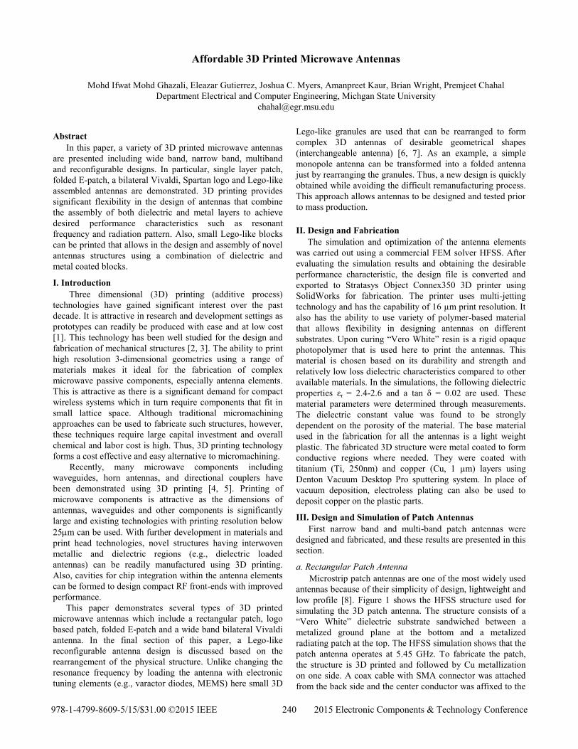
low profile [8]. Figure 1 shows the HFSS structure used for
simulating the 3D patch antenna. The structure consists of a
“Vero White” dielectric substrate sandwiched between a
metalized ground plane at the bottom and a metalized
radiating patch at the top. The HFSS simulation shows that the
patch antenna operates at 5.45 GHz. To fabricate the patch,
the structure is 3D printed and followed by Cu metallization
on one side. A coax cable with SMA connector was attached
from the back side and the center conductor was affixed to the
978-1-4799-8609-5/15/$31.00 ©2015 IEEE 240 2015 Electronic Components & Technology Conference
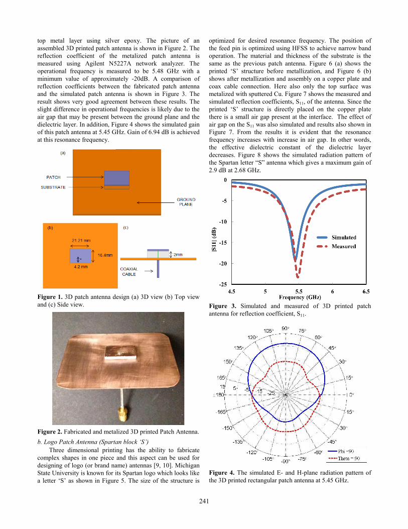
top metal layer using silver epoxy. The picture of an
assembled 3D printed patch antenna is shown in Figure 2. The
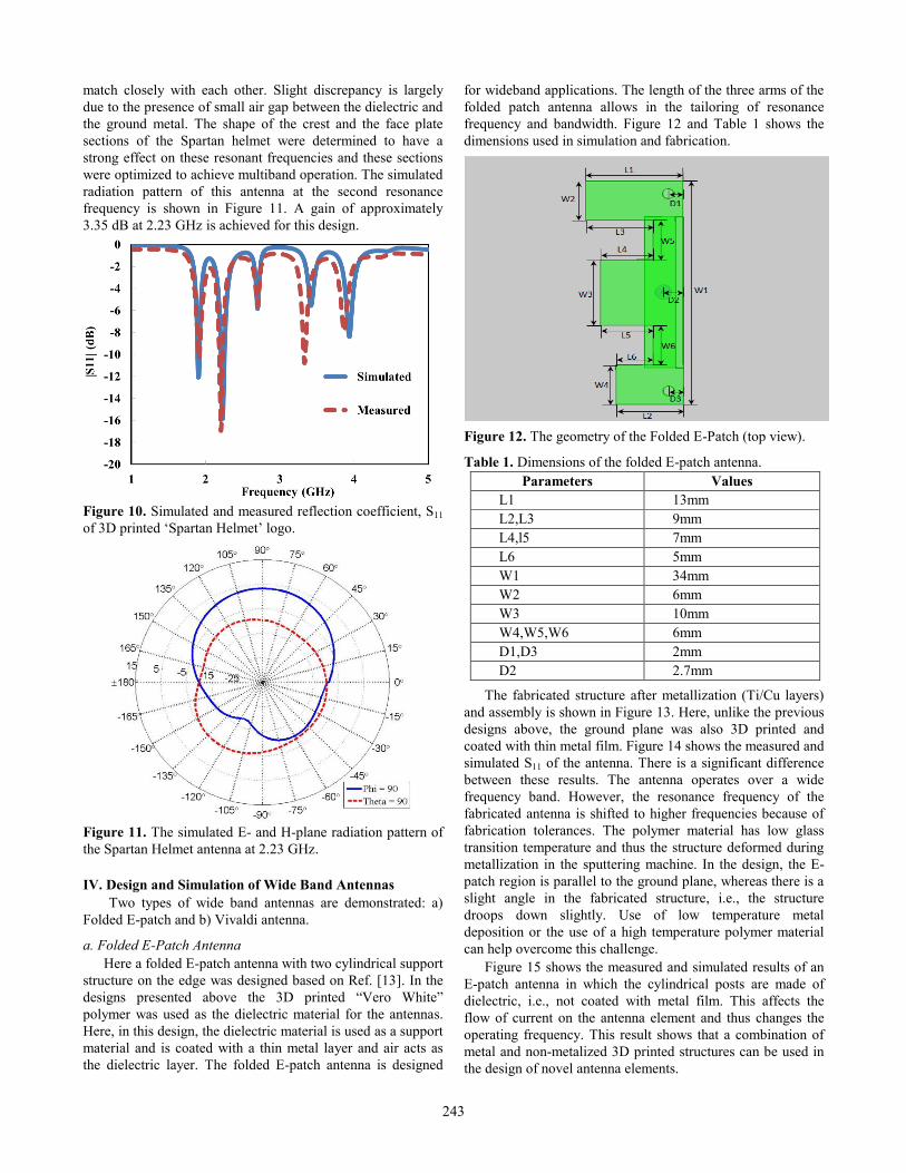
reflection coefficient of the metalized patch antenna is
measured using Agilent N5227A network analyzer. The
operational frequency is measured to be 5.48 GHz with a
minimum value of approximately -20dB. A comparison of
reflection coefficients between the fabricated patch antenna
and the simulated patch antenna is shown in Figure 3. The
result shows very good agreement between these results. The
slight difference in operational frequencies is likely due to the
air gap that may be present between the ground plane and the
dielectric layer. In addition, Figure 4 shows the simulated gain
of this patch antenna at 5.45 GHz. Gain of 6.94 dB is achieved
at this resonance frequency.
Figure 1. 3D patch antenna design (a) 3D view (b) Top view
and (c) Side view.
Figure 2. Fabricated and metalized 3D printed Patch Antenna.
b. Logo Patch Antenna (Spartan block ‘S’)
Three dimensional printing has the ability to fabricate
complex shapes in one piece and this aspect can be used for
designing of logo (or brand name) antennas [9, 10]. Michigan
State University is known for its Spartan logo which looks like
a letter ‘S’ as shown in Figure 5. The size of the structure is
optimized for desired resonance frequency. The position of
the feed pin is optimized using HFSS to achieve narrow band
operation. The material and thickness of the substrate is the
same as the previous patch antenna. Figure 6 (a) shows the
printed ‘S’ structure before metallization, and Figure 6 (b)
shows after metallization and assembly on a copper plate and
coax cable connection. Here also only the top surface was
metalized with sputtered Cu. Figure 7 shows the measured and
simulated reflection coefficients, S11, of the antenna. Since the
printed ‘S’ structure is directly placed on the copper plate
there is a small air gap present at the interface. The effect of
air gap on the S11 was also simulated and results also shown in
Figure 7. From the results it is evident that the resonance
frequency increases with increase in air gap. In other words,
the effective dielectric constant of the dielectric layer
decreases. Figure 8 shows the simulated radiation pattern of
the Spartan letter “S” antenna which gives a maximum gain of
2.9 dB at 2.68 GHz.
Figure 3. Simulated and measured of 3D printed patch
antenna for reflection coefficient, S11.
Figure 4. The simulated E- and H-plane radiation pattern of
the 3D printed rectangular patch antenna at 5.45 GHz.
241

Figure 5. 3D Spartan ‘S’ logo patch antenna design.
Figure 6. 3D printed Spartan ‘S’ logo (a) unmetalized
(b) metalized with copper platting as the ground.
Figure 7. Simulated and measured reflection coefficient, S11
of 3D printed Spartan ‘S’ logo with simulation for air gap.
Figure 8. The simulated radiation pattern on the E- and H-
plane of the Spartan ‘S’ logo patch antenna at 2.68GHz.
c. Logo Patch Antenna (Spartan helmet)
Due to limited space in electronic devices, having a single
functional narrowband antenna will limit its capability. To
overcome this limitation, a multiband antenna is desirable
[11]. Many designs have been studied in order to improve the
performance of multiband antennas such as multilayer patch
antennas, [12], as an example. Such antenna structures can
readily be fabricated using 3D printing. In a multiband design
antenna multiple current paths are necessary. This can be
achieved by using notch structures that can readily be 3D
printed. Another one of Michigan State University logos, ‘The
Spartan Helmet’ can be used to design a multiband antenna
element. Figure 9 shows a fabricated Spartan Helmet logo
antenna after metallization and assembly.
Figure 9. 3D printed Spartan Helmet logo (a) before
metallization and (b) after metallization and assembly.
Figure 10 shows the simulated and measured multiband
operational frequencies (S11) of this structure. The results
(b)
29.65 mm
(a)
(a)
(b)
242
match closely with each other. Slight discrepancy is largely
due to the presence of small air gap between the dielectric and
the ground metal. The shape of the crest and the face plate
sections of the Spartan helmet were determined to have a
strong effect on these resonant frequencies and these sections
were optimized to achieve multiband operation. The simulated
radiation pattern of this antenna at the second resonance
frequency is shown in Figure 11. A gain of approximately
3.35 dB at 2.23 GHz is achieved for this design.
Figure 10. Simulated and measured reflection coefficient, S11
of 3D printed ‘Spartan Helmet’ logo.
Figure 11. The simulated E- and H-plane radiation pattern of
the Spartan Helmet antenna at 2.23 GHz.
IV. Design and Simulation of Wide Band Antennas
Two types of wide band antennas are demonstrated: a)
Folded E-patch and b) Vivaldi antenna.
a. Folded E-Patch Antenna
Here a folded E-patch antenna with two cylindrical support
structure on the edge was designed based on Ref. [13]. In the
designs presented above the 3D printed “Vero White”
polymer was used as the dielectric material for the antennas.
Here, in this design, the dielectric material is used as a support
material and is coated with a thin metal layer and air acts as
the dielectric layer. The folded E-patch antenna is designed
for wideband applications. The length of the three arms of the
folded patch antenna allows in the tailoring of resonance
frequency and bandwidth. Figure 12 and Table 1 shows the
dimensions used in simulation and fabrication.
Figure 12. The geometry of the Folded E-Patch (top view).
Table 1. Dimensions of the folded E-patch antenna.
Parameters Values
L1 13mm
L2,L3 9mm
L4,l5 7mm
L6 5mm
W1 34mm
W2 6mm
W3 10mm
W4,W5,W6 6mm
D1,D3 2mm
D2 2.7mm
The fabricated structure after metallization (Ti/Cu layers)
and assembly is shown in Figure 13. Here, unlike the previous
designs above, the ground plane was also 3D printed and
coated with thin metal film. Figure 14 shows the measured and
simulated S11 of the antenna. There is a significant difference
between these results. The antenna operates over a wide
frequency band. However, the resonance frequency of the
fabricated antenna is shifted to higher frequencies because of
fabrication tolerances. The polymer material has low glass
transition temperature and thus the structure deformed during
metallization in the sputtering machine. In the design, the E-
patch region is parallel to the ground plane, whereas there is a
slight angle in the fabricated structure, i.e., the structure
droops down slightly. Use of low temperature metal
deposition or the use of a high temperature polymer material
can help overcome this challenge.
Figure 15 shows the measured and simulated results of an
E-patch antenna in which the cylindrical posts are made of
dielectric, i.e., not coated with metal film. This affects the
flow of current on the antenna element and thus changes the
operating frequency. This result shows that a combination of
metal and non-metalized 3D printed structures can be used in
the design of novel antenna elements.
243
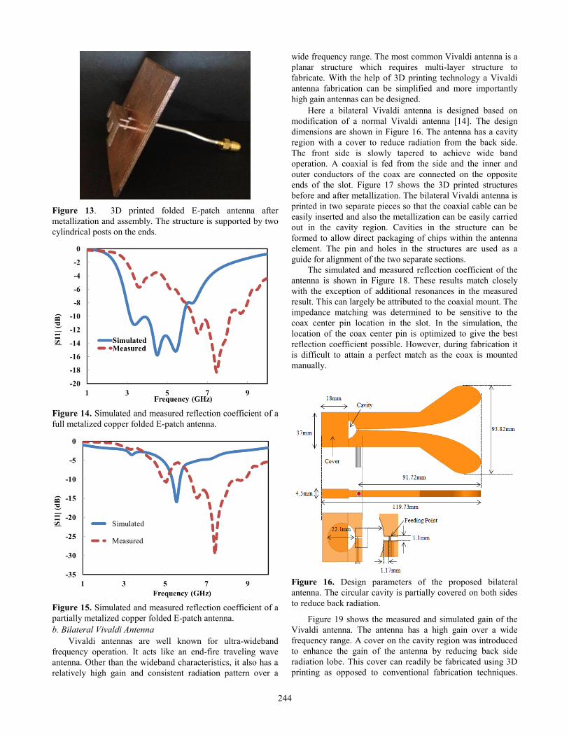
Figure 13. 3D printed folded E-patch antenna after
metallization and assembly. The structure is supported by two
cylindrical posts on the ends.
Figure 14. Simulated and measured reflection coefficient of a
full metalized copper folded E-patch antenna.
Figure 15. Simulated and measured reflection coefficient of a
partially metalized copper folded E-patch antenna.
b. Bilateral Vivaldi Antenna
Vivaldi antennas are well known for ultra-wideband
frequency operation. It acts like an end-fire traveling wave
antenna. Other than the wideband characteristics, it also has a
relatively high gain and consistent radiation pattern over a
wide frequency range. The most common Vivaldi antenna is a
planar structure which requires multi-layer structure to
fabricate. With the help of 3D printing technology a Vivaldi
antenna fabrication can be simplified and more importantly
high gain antennas can be designed.
Here a bilateral Vivaldi antenna is designed based on
modification of a normal Vivaldi antenna [14]. The design
dimensions are shown in Figure 16. The antenna has a cavity
region with a cover to reduce radiation from the back side.
The front side is slowly tapered to achieve wide band
operation. A coaxial is fed from the side and the inner and
outer conductors of the coax are connected on the opposite
ends of the slot. Figure 17 shows the 3D printed structures
before and after metallization. The bilateral Vivaldi antenna is
printed in two separate pieces so that the coaxial cable can be
easily inserted and also the metallization can be easily carried
out in the cavity region. Cavities in the structure can be
formed to allow direct packaging of chips within the antenna
element. The pin and holes in the structures are used as a
guide for alignment of the two separate sections.
The simulated and measured reflection coefficient of the
antenna is shown in Figure 18. These results match closely
with the exception of additional resonances in the measured
result. This can largely be attributed to the coaxial mount. The
impedance matching was determined to be sensitive to the
coax center pin location in the slot. In the simulation, the
location of the coax center pin is optimized to give the best
reflection coefficient possible. However, during fabrication it
is difficult to attain a perfect match as the coax is mounted
manually.
Figure 16. Design parameters of the proposed bilateral
antenna. The circular cavity is partially covered on both sides
to reduce back radiation.
Figure 19 shows the measured and simulated gain of the
Vivaldi antenna. The antenna has a high gain over a wide
frequency range. A cover on the cavity region was introduced
to enhance the gain of the antenna by reducing back side
radiation lobe. This cover can readily be fabricated using 3D
printing as opposed to conventional fabrication techniques.
244
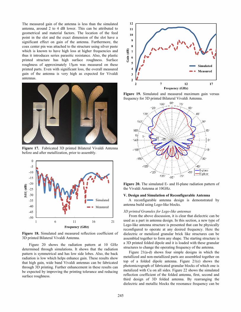
The measured gain of the antenna is less than the simulated
antenna, around 2 to 4 dB lower. This can be attributed to
geometrical and material factors. The location of the feed
point in the slot and the exact dimension of the slot have a
significant effect on gain of the antenna. Furthermore, the
coax center pin was attached to the structure using silver paste
which is known to have high loss at higher frequencies and
thus it introduces series parasitic resistance. Also, the plastic
printed structure has high surface roughness. Surface
roughness of approximately 15m was measured on these
printed parts. Even with significant loss, the overall measured
gain of the antenna is very high as expected for Vivaldi
antennas.
Figure 17. Fabricated 3D printed Bilateral Vivaldi Antenna
before and after metallization, prior to assembly.
Figure 18. Simulated and measured reflection coefficient of
3D printed Bilateral Vivaldi Antenna.
Figure 20 shows the radiation pattern at 10 GHz
determined through simulations. It shows that the radiation
pattern is symmetrical and has low side lobes. Also, the back
radiation is low which helps enhance gain. These results show
that high gain, wide band Vivaldi antennas can be fabricated
through 3D printing. Further enhancement in these results can
be expected by improving the printing tolerance and reducing
surface roughness.
Figure 19. Simulated and measured maximum gain versus
frequency for 3D printed Bilateral Vivaldi Antenna.
Figure 20. The simulated E- and H-plane radiation pattern of
the Vivaldi Antenna at 10GHz.
V. Design and Simulation of Reconfigurable Antenna
A reconfigurable antenna design is demonstrated by
antenna build using Lego-like blocks.
3D printed Granules for Lego-like antennas
From the above discussion, it is clear that dielectric can be
used as a part in antenna design. In this section, a new type of
Lego-like antenna structure is presented that can be physically
reconfigured to operate at any desired frequency. Here the
dielectric or metalized granular brick like structures can be
assembled together to form any shape. The starting structure is
a 3D printed folded dipole and it is loaded with these granular
structures to change the operating frequency of the antenna.
Figure 21(a-d) shows four simple designs in which the
metallized and non-metallized parts are assembled together on
top of a folded dipole antenna. Figure 21(e) shows the
photomicrograph of fabricated granular blocks of which one is
metalized with Cu on all sides. Figure 22 shows the simulated
reflection coefficient of the folded antenna, first, second and
third design of 3D folded antenna. By rearranging the
dielectric and metallic blocks the resonance frequency can be
245
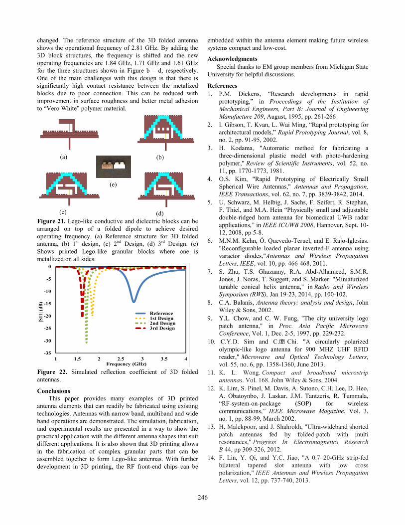
changed. The reference structure of the 3D folded antenna
shows the operational frequency of 2.81 GHz. By adding the
3D block structures, the frequency is shifted and the new
operating frequencies are 1.84 GHz, 1.71 GHz and 1.61 GHz
for the three structures shown in Figure b – d, respectively.
One of the main challenges with this design is that there is
significantly high contact resistance between the metalized
blocks due to poor connection. This can be reduced with
improvement in surface roughness and better metal adhesion
to “Vero White” polymer material.
Figure 21. Lego-like conductive and dielectric blocks can be
arranged on top of a folded dipole to achieve desired
operating frequency. (a) Reference structure for 3D folded
antenna, (b) 1st design, (c) 2
nd Design, (d) 3
rd Design. (e)
Shows printed Lego-like granular blocks where one is
metallized on all sides.
Figure 22. Simulated reflection coefficient of 3D folded
antennas.
Conclusions
This paper provides many examples of 3D printed
antenna elements that can readily be fabricated using existing
technologies. Antennas with narrow band, multiband and wide
band operations are demonstrated. The simulation, fabrication,
and experimental results are presented in a way to show the
practical application with the different antenna shapes that suit
different applications. It is also shown that 3D printing allows
in the fabrication of complex granular parts that can be
assembled together to form Lego-like antennas. With further
development in 3D printing, the RF front-end chips can be
embedded within the antenna element making future wireless
systems compact and low-cost.
Acknowledgments
Special thanks to EM group members from Michigan State
University for helpful discussions.
References
1. P.M. Dickens, “Research developments in rapid
prototyping,” in Proceedings of the Institution of
Mechanical Engineers, Part B: Journal of Engineering
Manufacture 209, August, 1995, pp. 261-266
2. I. Gibson, T. Kvan, L. Wai Ming, “Rapid prototyping for
architectural models,” Rapid Prototyping Journal, vol. 8,
no. 2, pp. 91-95, 2002.
3. H. Kodama, "Automatic method for fabricating a
three‐dimensional plastic model with photo‐hardening
polymer," Review of Scientific Instruments, vol. 52, no.
11, pp. 1770-1773, 1981.
4. O.S. Kim, "Rapid Prototyping of Electrically Small
Spherical Wire Antennas," Antennas and Propagation,
IEEE Transactions, vol. 62, no. 7, pp. 3839-3842, 2014.
5. U. Schwarz, M. Helbig, J. Sachs, F. Seifert, R. Stephan,
F. Thiel, and M.A. Hein “Physically small and adjustable
double-ridged horn antenna for biomedical UWB radar
applications,” in IEEE ICUWB 2008, Hannover, Sept. 10-
12, 2008, pp 5-8.
6. M.N.M. Kehn, Ó. Quevedo-Teruel, and E. Rajo-Iglesias.
"Reconfigurable loaded planar inverted-F antenna using
varactor diodes,"Antennas and Wireless Propagation
Letters, IEEE, vol. 10, pp. 466-468, 2011.
7. S. Zhu, T.S. Ghazaany, R.A. Abd-Alhameed, S.M.R.
Jones, J. Noras, T. Suggett, and S. Marker. "Miniaturized
tunable conical helix antenna," in Radio and Wireless
Symposium (RWS), Jan 19-23, 2014, pp. 100-102.
8. C.A. Balanis, Antenna theory: analysis and design, John
Wiley & Sons, 2002.
9. Y.L. Chow, and C. W. Fung, "The city university logo
patch antenna," in Proc. Asia Pacific Microwave
Conference, Vol. 1, Dec. 2-5, 1997, pp. 229-232.
10. C.Y.D. Sim and C.J. Chi. "A circularly polarized
olympic‐like logo antenna for 900 MHZ UHF RFID
reader," Microwave and Optical Technology Letters,
vol. 55, no. 6, pp. 1358-1360, June 2013.
11. K. L. Wong. Compact and broadband microstrip
antennas. Vol. 168. John Wiley & Sons, 2004.
12. K. Lim, S. Pinel, M. Davis, A. Sutono, C.H. Lee, D. Heo,
A. Obatoynbo, J. Laskar. J.M. Tantzeris, R. Tummala,
“RF-system-on-package (SOP) for wireless
communications,” IEEE Microwave Magazine, Vol. 3,
no. 1, pp. 88-99, March 2002.
13. H. Malekpoor, and J. Shahrokh, "Ultra-wideband shorted
patch antennas fed by folded-patch with multi
resonances," Progress In Electromagnetics Research
B 44, pp 309-326, 2012.
14. F. Lin, Y. Qi, and Y.C. Jiao, "A 0.7–20-GHz strip-fed
bilateral tapered slot antenna with low cross
polarization," IEEE Antennas and Wireless Propagation
Letters, vol. 12, pp. 737-740, 2013.
(a) (b)
(c) (d)
(e)
246