afml-tr-79-4122 evell
TRANSCRIPT
AFML-TR-79-4122
~kL EVELLý,) LIQUID AND SOLID PARTICLE IMPACT EROSION
George F. Schmitt, Jr.
Coatings and Thermal Protection Materials BranchNonmetallic Materials Division
>J November 1979
C TECHNICAL REPORT AFML-TR-79-4122
SmFinal Report for Period March 1979 - June 1979
cma
Approved for public release; distribution unlimited.
1'wnnri I
T- E13 141AIR FORCE MATERIALS LABORATORY ~~~l,AIR FORCE WRIGHT AERONAUTICAL LABORATORIESAIR FORCE SYSTEMS COMMAND
WRIGHT-PATTERSON AIR FORCE BASE, OHIO 45433
~O 2 11 fl2 [I'
N(O!ZCN
When Government drawings, specifications, or other data are used for any pur-pose other than in connection with a definitely related 0overnment proculrentOperation, the United States Government thereby incurs no responsibility nor anyobligation whatsoever, and the fact that the goverrnment ma have formulated,furnished, or in any way supplied the said drawings, specieications, or otherdata, is nct to be regarded by implication or otherwise as in any manner licen-sing the holder or any ohahr person or corporation, or conveying any rights orpermission to manufacture, use, or sell any patented invention that my in anyway be related thereto,
This technical report has been reviewed and is approved for publication.
GEORGE F. SCHMITT, JR.Project Engineer
FOR 2W1 COMMANDBER:
M. KELBLE, ChiefNonmetallic Materials DivisionAir Force Materials Laboratory
"2f your address has changed, if you wish to be removed from our miling list,or 1I Lne addressee is no longer employed by your organization please notifyAFLj ,w-P APB, OH 45433 to help us maintain a current maillng list",
Copies of this report should not be returned unless return is required by se.curity considerations, contractual obligations, or notice on a specific doiumant,Al POt ORIL/56710/21 January, 1950 -1330
UNCLARSTIIrflnSEC.RITt' CLASS-FIrATION OF rHIF 04,13 'Ie~t I~fta iXroted) ____________________
S REPORT DCMNAINPAGE BEORE~r COMPLETING FORM
AFML-TR-79-4l22 ----LA -TfLE (and Suhtt lle)I 9_6z&&" ORE
.... .... ...... -. . -- / Finala Spt Mard~17
( (:.' LIQUID AND SOCLID PARTICLE IMPACT EROIN -Jn 7
7. AU THOR(A) AT04GATNME(&
( O George F/cmt
2. PERII-ORMING ORGANIZATION NAME AND ADDRESS IF pr r 7F'A ;I~ET, -PROJCT, SPAir Force Materials Laboratory (MBE) Ip.E'.OR UNITF NPUroject242
Air Force Systems Command PE,612,Poet22
Wright-Patterson AFB, OH 45433 Task242201, okUiii. CONTROLLINO OFFIICE NAME AND ADDIRISSS
Same as block 9 Nvuw*
14. MONITORING AOIENCY NAME &AODDRESS(il different fromt Controlling OffiIIe) is. EEcLJRiTy CLASS. (at lthi report)
~< j3~ -"--~*Unclassified
". '.'&~ Ti. DKCJASSIPICATlON/DOWNO0RADINO
II. DISTRINUTION STATEEMENT (of thisl Report)
Approved for public release; distribution unlimited,
III. DISTRINUTION STATEMENT (of th. abstrant entered In Block 20, )1 differenItfrom" Report)
Same as block 16
IS. SUPPLEMENTARY NOTES
I9. KRY WORDS (Continue ort reverse aide it nveesary and Identify by block number)Liquid Impact Erosion ResistanceSolid Particle Impact Erosion Design TechniquesErosion Erosion MechanismsRain Erosion,Ero~iou Theory
20. ~U~~ACT (Continue on ree, ai1& It necessary' and identify by block number)2 The state-ofe-thae#-art in liquid drop Impact and solid particle impact
erosion is reviewed with emphasis on erosion mechanisms, prediction tech-niques, and materials properties effects. Erosion data sources, materialsused to resist erosion, and design techniques are described. A bibliographyof key references in the erosion literature in also presented.
FOR 43 EDTION OF I NOV 46 It 0U50LRTIK UNCLASSIFIED
SECURITY CLASSIFICATION OF THIS PAGE (II'ien Data 1ntered)
AFML-TR-79-4122
FOREWORD
This report was prepared by George F. Schmitt, Jr. of the Coatings
and Thermal Protection Materials Branch, Nonmetallic Materials Division,
Air Force Materials Laboratory (MBE), Wright-Patterson Air Force Base,
Ohio. The work was initiated under Project No. 2422, "Protective Coatings
and Materials," Task No. 242201, "Coatings for Aircraft and Spacecraft."
The report covers research conducted during the period March 1979 to
June 1979. The report was submitted in July 1979.
This report was commissluned by the ASME Wear Control Handbook, a
centennial project of the American Society of Mechanical Engineers, New
York, N.Y. and is contributed by the author and the Air Force to that
publication.
J 't
, L "Q
?ii
AFML-TR-79-4122
TABLE OF CONTENTS
SECTION PAGE
I GENERAL DESCRIPTION OF EROSION PHENOMENA I
II MECHANISMS OF EROSION DAMAGE 3
1. Liquid Impact 3
2. Modes of Liquid Impact Damage 4
3. Solid Impact on Ductile Metals 8
4. Solid Impact on Brittle Metals 11
III EROSION PREDICTION TECHNIQUES 15
1. Thiruvengadam's Theory of Liquid Impact Erosion 15
2. Springer's Theory of Liquid Impact Erosion 18
3. Brittle Material - Liquid Impact Theories 20
4. Hertzlan Impact Theories 21
5. Brittle Material Models 23
6. Empirical Models 24
IV EROSION DATA SOURCES 26
1. Liquid Impact 26
2. Solid Impact 27
V MATERIALS PROPERTIES EFFECTS 29
1. Metals 29
2. Polymers 30
3. Ceramics 31
VI MATERIALS TO RESIST EROSION 33
1. Metals 33
2. Ceramics 34
3. Elastomers 36
4. Plastics 37
VII DESIGN TECHNIQUES TO AVOID EROSION 38
1. Reduction in Velocity 38
2. Reduction in Impact Angle 38
3. Reduction in Droplet Size or Particle Diameter 39
4. Particle Concentration Reduction 39
AFML-TR-79-4122
TABLE OF CONTENTS (Cont)
SECTION PAGE
5. Leading Edge Radius Effects 406. Flush Mounting/Gradual Bends 40
7. Geometry and Scale-up 41
VIII CONCLUSIONS 43
REFERENCES 44
BIBLIOGRAPHY 52
vi
AFML...TR-79-4122
LIST OF ILLUSTRATIONS
FIGURE PAGE
1 Damage Modes Due to Liquid Drop Impingement 54
2 Erosion Rate/Cumulative Erosion 55
3 Dependence of Erosion Rate on Attack Angle isShown Schematically for Ductile and Brittle Materials 56
4 Impact of Rectangular Plate Showing Definitions of
Impact Angle and Rake Angle 56
5 Sections Through Impact Craters Showing Typical Shapes 57
6 Thiruvengadam's Erosion Strength Estimator 57
la Schematic of the Experimental Results 58
7b The Solution Model 58
8 Incubation Period Versus S/P 59
9 Comparison of Springer Model with Experimental Results 60
10 Pressure Distribution Under Impacting Water Drop 61
11 Comparison of Rain Erosion Behavior of the DifferentMaterial Classes 62
12 Rain Erosion of Some Glasses, Ceramics, and a SpecialSapphire 62
13 Relative Erosion Performance of Commercially AvailableMetal s 63
14 Ceramics (90-Deg Impingement) 64
15 Kennametal Cemented Carbides (90-Deg Impingement) 64
16 AFML Rotating Arm Apparatus 65
vii
AFML-TR-7g-4122
LIST OF TABLES
TABLE PAGE
1 Impact Conditions for Water Drops 66
2 Descripticn of Data and Symbols Used in Figures 8And 9 67
3 Rain Erosion Equation Constants, Nose Tip Materials 70
4 Room Temperature Erosion Test Results 71
5 700 Degrees Centigrade Erosion Test Results 72
6 Room Temperature Erosion Test Results on CoatedMaterials 73
7 700 Degrees Centigrade Erosion Test Results onCoated Materials 73
8 Abbreviations Used in Tables 4 and 7 74
viii
AFML-TR-79-4122
SECTION I
GENERAL DESCRIPTION OF EROSION PHENOMENA
Erosion of materials and components caused by the impact of liquiddrops or solid particles can be a life-limiting phenomenon for the operation
of systems in erosive environments.
Rain erosion or material damage due to flight through natural rainstormshas been a concern for aircraft and missiles since World War II. The
impact of liquid drops which are condensed steam entrained in the airflow
has been a major concern in the operation of large hydroelectric plant
steam turbines for many years. Other systems in which liquid droplets of
substantial size may impact material surfaces causing damage are also
subject to erosive attack, An example would be a fuel injection device.
Solid particle Impact erosion has been receiving Increasing attention
in recent years because of the research and development of coal conversion
plants with their need for movement and flow of solid particles into
various equipment in these plants. The impact of these particles on movingblades, valve constrictions, pipe joints and bends, and other surfaces
has resulted in severe erosion. Solid particle erosion has been a concern
for aerospace systems for many years including sand erosion on leading
edges of helicopter blades, ingestion and erosion of leading and trailing
edges of jet engine blades and vanes, and solid particle impacts on glassdomes of captively carried, optically guided missiles or laminated plastic
transparent windshields and canopies.
Coupled effects are a significant factor in the erosion of materials.Although they will not be treated in this section, they should be mentioned.
An example is -the combined corrosion/impact erosion experienced in coal
conversion where most systems operate at elevated temperatures in environ-
ments which are quite corrosive and erosive. The sulfidation/oxidation/
material removal due to impact mechanisms is extremely complex and not
well understood.
1F
* .I~
AFML-TR-79-4122
Another example of coupled effects is the combined ablation-erosion
for reentry vehicle nosetips and heat shields of high velocity missiles
as they reenter the atmosphere and pass through high cirrus ice clouds
or precipitating snow or rain. The erosion impact material removal and
the ablative heat transfer/vaporization/thermomechanical removal occur
essentially simultaneously and each influences the other by its effects
on the material involved.
Beneficial uses of erosive processes are few but significant. Most
people are aware of the use of sand blasting for cleaning purposes.
However, the extent to which liquid Jet cutting (an impact process using
jets of liquid rather than discrete drops) has been adopted for mining,
tunneling, cutting rock, cutting lumber, and advanced graphite-epoxy
composite materials is not generally known. The use of liquid jets for
digging pole holes or trenching for power utilities has been explored
and found to be feasible and potentially cost effective.
This section will deal with the detrimental effects of liquid and
solid particle impact erosion and ways of combatting this phenomenon,
2
2U~t2'~I
AFML-TR-79-4122
SECTION II
MECHANISMS OF EROSION DAMAGE
The response of engineering materials to the impingement of liquid
drops or solid particles varies greatly depending on the class of materials,
the state to which those materials have been exposed (i.e., thermal
history, previous stresses in the material, surface treatments) and the
environmental parameters associated with the erosion process such as
impact velocity, impact angle, particle type and size, and coupled effects
like ablation or corrosion.
1. LIQUID IMPACT
Categorization of the types of response of materials to liquid
impact is shown in Table 1 as adapted from Adler (Reference 1). The free
fall category refers to falling rain, impacting porous soil and causing
ground erosion. The subsonic, supersonic, and hypersonic velocity regimes
refer to impact below the velocity of sound in air (up to approximately
342 m/s), between 342 m/s and the dilatational wave speed In the material,
and velocities greater than the dilatational wave speed respectively.
Accordingly, most materials being impacted are rigid and analyses have
been developed. The brittle response is an elastic-brittle response and
is representative of the erosion of ceramics, glasses, uncoated composite
materials, and thermosetting plastics. Non-brittle refers to the response
of ductile materials such as mo.t metals and thermoplastic polymers. The
layered designation is included because protective coatings of elastomeric
polymers, thin ceramics and metals over plastics and composites, and metal
facings over other, metal substrates have been successful in combatting
erosion on aircraft radome and composite structures, composite missile
radomes, and for steam turbine blade protection. The response of these
layered materials is a function of the impedance match between coating
and substrate, the degree of adhesion of the coating, and the impact
conditions.
3
AFML-TR-79-4122
The composite material response is designated separately, although
relatively little exists in the ability to analyze and design reinforced
composites for improved erosion performance, because these materials are
becoming more widely used for structural application when erosion is a
major concern. Principal attempts to construct composite materials have
concentrated on the design of carbon-carbon graphitic materials forre-entry vehicle thermal protection (Reference 2).
2. MODES OF LIQUID IMPACT DAMAGE
The response of nominally brittle materials to liquid impact iscracking of the surface due to the direct deformation impact loading on
the surface. This cracking is typically in the form of disconnectedannular ring segments which eventually intersect under continued impinge-ment and result in chips of material being removed. Eventually large
scale surface roughening and total original surface removal will occur,
If the impact velocity is great enough, individual drops will causemassive fracture. A schematic of the damage modes In brittle materials
due to liquid drop impact is shown in Figure l'(Reference 3).
In porous ceramic materials such as reaction-sintered silicon nitride,
the porosity provides a means of reducing crack propagation to prevent
catastrophic fracture which can occur in denser ceramics,
The annular cracking which occurs in chalcogenide infrared windows
such as zinc sulfide and zinc seleni-de can result in a loss of transmission
through the window due to diffraction and absorption of the energy.However, this loss of transmission can occur when the material surface is
not severely damaged or when material weight loss has not begun; it is
caused by the in-depth propagation and intersection of droplet impact-
caused ring fractures (Reference 4).
The erosion of thermosetting polymers in bulk form or as matrix
resins in laminated or chopped fiber-reinforced composites takes the form
of chunking on the surface. This breakage of the resin causes fibers
(individually or as cloth in a laminate) to be partially exposed; subse-
quent impacts of droplets and the lateral outflow from these droplets
4
$I
AFML-TR-79-4122
interact with these fibers causing column buckling or bending with frac-
ture and removal
The erosion of ductile materials such as metals and thermoplastic
polyme's assumes the form of initial surface depressions with upraised
edges. These edges are susceptible to the lateral outflow jetting from
the impacting drop leading to erosion pit nucleation. The depressions
themselves are sites of local stress concentration but do not contribute
to material removal (Reference 1).
By contrast, erosion pit nucleation exhibits a different sequence
in Haynes alloy Stellite 6-B, which has been widely used as a remedy and,
in fact, is the state-of-the-art for steam turbine blade erosion protection
(Reference 5). In the wrought condition, this alloy contains 10 volume
percent dispersion of coarse iron carbide in an alloyed cobalt matrix.
Carbide/matrix cracking along with cracking of slip lines in the matrix
is the initial damage followed by subsequent metal removal due to carbide
particle ejection caused by lateral outflow. These carbide removal sites
then act as erosion pit nucleation sites.
A major contribution to the material removal process is the repeated
loadings of the surface during multiple impacts. At least three
explanations have evolved to explain the removal sequence. One expla-
nation finds a correspondence between erosion and fetigue in metals;
some experimental evidence exists in the appearance of eroded samples
(Reference 6). A fatigue theory has been developed by Springer (Reference
7) which will be discussed in a later section.
In experiments on titanium-6AI-4V alloy, Adler and Vyhnal (Reference
8) found that the material removal was caused by a tunneling phenomenon
due to hydraulit penetration and surface upheaval of regions which had
been undermined by joining of cracks which originated at erosion pits.
These tests were for water drop impacts with an imposed pressure of one
half the yield strength of the alloy.
5
AFML-TR-79-41 22
By contrast, Rieger (Reference 9) attributes the material removal
to plastic deformation resulting in intense local concentrations of
crystalline dislocations such that the internal stresses in these con-
centrated dislocation areas exceed the fracture strength forming a crack.
The extension and joining of these cracks results in mass loss.
As described in the preceding paragraphs, the mechanisms of material
removal even in nominally ductile metals are numerous and depend upon the
microstructure of the alloy. The general form of the erosion and erosion
rate as a function of exposure is shown in Figr 2 (Reference l). The
periods as labeled in this figure reflect the common terminology used to
describe different portions of the process (Reference 10). The incubation
period in which no mass loss occurs, although the damage may be accumulating
in the form of surface deformation, cracking, or fatigue is perhaps a
characteristic of individual materials and is often used as a measure of
erosion performance. The slope of the erosion vs time curve is also an
important characteristic of materials. Theories have been developed which
attempt to incorporate these features (References 7, 11, 12) and will be
discussed in Section III.
Obviously, at very high impact velocities where each drop impact may
cause material removal, the existence of incubation periods and changing
erosion rates is not descriptive of the phenomena which occur.
The deformation modes and erosion mechanisms for polymeric materials
caused by liquid impact have been identified by Adler and Hooker (Reference
12) and Schmitt (Reference 13). At subsonic velocities, most polymeric
materials such as polycarbonate, polysulfone, and polymethylmethacrylate
exhibit ring crack formation after drop impact but maintain a central
region of undamaged material within this ring crack. The damage was
concentrated in an annular zone associated with the region of maximum
pressure from the drop impact.
The response of polymeric materials has been found to be different
for thermoplastics such as polyethylene, nylon, polyphenylene oxide, and
thermosets such as polyimides and epoxies, In these materials, the
____ ____ ____ ____ I
AFML-TR-79-41 22
addition of reinforcement to thermoplastics is detrimental to erosion
performance because the fibers tend to break out under repeated impinge-
ment enhancing the mass loss, The thermosetting polymers benefit byreinforcement because the fibers reduce massive breakage and chunking of
the brittle resin (Reference 14).
Recent studies by Gorham, Matthewson and Field (Reference 15) on
reinforced and non-reinforced thermosetting and thermoplastic polymers
have confirmed the above conclusions and determined that absorption of the
impact energy by ductile failure in composites is desirable and the thermo-
plastics provide this.
The liquid impact erosion of elastomeric coatings has been extensively
studied (References 16, 17, 18) and much development of polyurethane andfluorocarbon coatings has been conducted for protection of aircraft radomes
and composite surfaces. The polyurethane coatings developed in 1966-6greplaced neoprene coatings which has been in use since the early 1950's.
The fluorocarbons have been developed since 1972 for higher temperature
applications. Development has been empirically based through extensivescreening on rotating arm rain erosion simulation apparatus (Reference 19).
The neoprene coatings erode under liquid impact by a gradual rough-
ening of the surface and eventual adhesion loss as the coating is loosenedfrom the surface and torn by subsequent impact. The polyurethane coating
fails by an isolated hole typically the size of a pencil point which fails
to the substrate while the surrounding area of the coating remains intact,looking as though it has not been exposed. The fluorocarbon coating erodes
by chunking of pieces from its surface and gradual wearing away until the
substrate is exposed.
Other brittle polymeric coatings such as epoxies, silicones, polyesters,acrylics, and nonelastomeric polyurethanes fail by brittle rupture and/or
spall of the coating very rapidly upon impact, All of the above behaviorapplies to low velocity impact conditions.
7
AFML-TR-79-4122
3. SOLID IMPACTS ON DUCTILE METALS
Removal of material by solid particle impact is perhaps the mostpervasive of the erosion processes due to growing utilization of coal in
fine particulate form in energy conversion plants, other combustion product
particulates in flue gases in these plants, solid impact in Jet engines
and on helicopter rotor blades, and even in large scale turbines due to
spall and subsequent impact of oxide particles on downstream blades and
surfaces. A major National Materials Advisory Board study (Reference 20)
has addressed the erosion question of the energy conversion processes
and the reader is referred to it.
As is the case with liquid impact, several mechanisms are recognized
as occurring depending upon the ductility or brittleness of the material
being impacted,
A schematic of the features of erosion on ductile and brittle
materials as a function of angle is shown in Figure 3 (Reference 21),
The understanding of the mechanisms has been discussed in three recent
papers and will be summarized here (References 22, 23, 24).
The elements of ductile metal erosion by solid particles at low to
moderate velocities parallel those of liquid impact in that surface
deformation without mass loss initially occurs followed by a removal
process which has been the subject of much controversy and theory
development.
For ductile metals, the maximum erosion occurs at an impingement
angle of approximately 20 degrees (normal impact being 90 degrees).
This behavior was originally modeled by Finnie and co-workers (Reference
22) by considering the abrasive cutting by a rigid angular particle in
the surface of a ductile metal. A constant ratio of normal to tangential
force is assumed with a force vector of constant direction. In this
theory, the volume of material removed is a function of the mass impacting,
velocity-of-impact squared, the impact angle, and inversely proportional
to the horizontal component of flow pressure which is related to the
8
S.... .... _ . ..... .
AFML-TR-79-41 22
hardness between the particle and the material. This approach does not
describe the erosion of ductile materials at high impingement angles
(greater than 45 degrees) adequately.
A classic analysis by Bitter (Reference 25) described the erosion
process as consisting of two simultaneous processes: cutting wear which
dominates at low angles, and deformation wear which dominates at high
angles. This work is often referenced in erosion literature.
Tilly and co-workers (Reference 26) described a two-stage process
whereby particles, instead of being rigid, produce erosion by impact and
then fragment to produce additional erosion. The fragmentation and
outward flow of particle fragments cause the erosion at 90 degrees,
according to Tilly et al, and can be used to explain the velocity
dependence of erosion as greater than two as observed experimentally.
Numerous investigations (Reference 24), for example, have shown velocity
exponents of 2.3 and greater and increased fragmentation at higher
velocities was used to explain this. This fragmentation included the
particle size effect which had been observed experimentally since larger
particles would be more prone to fragment and produce additional damage
than small ones.
Smeltzer, Gulden and Compton (Reference 27) attribute the erosion
mechanism to localized meltinq during impact with attachment of surface
material to impacting particles. Although experimental evidence provides
some basis for these conclusions, the theory has not been widely ac-
cepted.
An energy balance between the kinetic energy of the particle and
the work expended during indentation forms the basis for the model of
Sheldon and Kanhere (Reference 28) which relates the erosion resistance
of the material (at 90 degrees impact) to the Vickers' hardness to the
2/3 power.
9
AFML-TR-79-4122
Experiments by Hutchings using idealized rectangular plates and
spherical particles have identified three mechanisms which are operative
in ductile metal erosion (Reference 22). These are: (1) Plowing
deformation resulting in a raised lip on the trailing edge of the crater
which was original material pushed up by the rounded surface of a particle;
(2) Type I cutting which results in a triangular indentation which Is
pushed up into a large lip at the exit end of the crater; and (3) Type II
cutting in which the plate rotates backward upon impact resulting in a
smooth shallow crater from which all material is removed. Type I cutting
is observed on plates with a negative rake angle which rotate forward in
impact (Figure 4). A plate with rake angles between 0 and -17 degrees
exhibits Type II cutting behavior. Examples of these three craters are
shown in Figures 5a, 5b, and 5c.
Analyses of the above craters show crater volumes proportional to
the energy lost by the projectile in both plowing an-i Type I cutting;
however, velocity exponents are 2.4 for plowing and 2,0 for Type I
cutting. The assumption which contrasts Hutching's analysis with that
of Finnie Is a constant yield pressure acting over the area of the
particle which is plastically deforming the substrate, leading to a
continually changing direction of the force vector during impact
(Reference 23).
Normal (90-degree) impact erosion of ductile metals is attributed
to a wide variety of mechanisms including work hardening and embrittle-
ment, fracture of solid particles on impact with subsequent outward flow
of fragments, extrusion of surface, delamination of subsurface material,
melting, and low cycle fatigue. Finnie (Reference 22) describes the
condition of the surface as an extrusion of material as a result of
continuous pounding of the surface until ductile fracture occurs. This
removed material is flake-like in nature. Microscopic examinations
eliminate embrittlement, fragmentation of particles, and melting asmechanisms with extrusion, low cycle fatigue, and delamination wear
remaining as possible explanations.
10
AFML-TR-79-4122
The role of particle embedment on the steady state erosion of ductilematerials is beginning to be explored, Ives and Ruff (Reference 21)
have found the embedded particles to be much smaller than the incident
particles resulting from fragmentation upon collision. The resultingmixed layer of deformed metal and embedded fragments is what is impacted
and removed by subsequent impacts.
The role of temperature in the ductile erosion process Is not well
understood because much of the past research has concentrated on room
temperature testing. However, considerable emphasis is now being placedon elevated temperature erosive processes (Reference 20),
Correlations between thermal properties of materials and erosion
rates have been developed by Ascarelli (Reference 29) for pure metalswith the product of the linear thermal expansion co-efficient, which isthe temperature rise required for melting and the bulk modulus of themetal. Other correlations also exist with the following properties:
(1) product of density, specific heat and temperature rise required for
melting, (2) melting point, and (3) the cube root of the mean molecularweight divided by the thermal conductivity, the enthalpy of melting, themelting temperature, and the cube root of the material density. It is
not clear that thermal properties really have significant influence on
erosion resistance of metals.
Strain rate properties appear to have very significant influence
on the erosion resistance of materials since the strain rates are typically
106 (Sec" 1 ) or greater. Conventional materials properties are measured
at low strain rates and hence poor correlation between erosion rates and
conventional properties is found.
4. SOLID IMPACT ON BRITTLE MATERIALS
In contrast to the erosion of ductile materials where erosion Ismaximum at an impingement angle of 20 to 30 degrees, the erosion of
brittle materials is a maximum at 90 degrees (normal impact). Figure 2gives a schematic representation of typical brittle material erosion as
a function of angle,
hI
AFML-TR-79-4122
The erosion of ceramics, glasses, and thermosetting polymer matrices
in composite materials by solid Impact is receiving increased emphasis
because ceramics and composites are being employed for engine applications
where dust ingestion is a concern and ceramics are being employed as
refractory liners in energy conversion equipment. Glasses and ceramics
are utilized as optical domes and radomes of tactical missiles where solid
particle impact during captive carry on the aircraft is a concern. The
use of fiber-reinforced composites on helicopter rotor blades which are
operated in sandy or dusty environments has not only caused study of the
erosion behavior of these materials but has resulted in the development
of state-of-the-art protective coatings schemes including electroplated
nickel and polyurethane for erosion protection. A similar situation
exists for composite jet engine blades and vanes which must also be
protected.
The impact of solid particles on brittle materials has been analyzed
using the Hertzian theory of impact for the collision of elastic bodies
in an elastic half-space (References 1, 23, 30, 31). Although the quasi-
static stress distributions from this analysis are not accurate at moderate
impact velocities, considerably wider applicability of the estimates for
sizes of contact zones and durations of impact has been found than would
be expected based on the assumptions in the theory,
The cone and ring cracks which form in a Hertzian impact are presumed
to intersect, and with a sufficient number of them, mass loss will occur-
by breakout of chunks of material. Radial cracking occurs and results in
strength degradation, This process has been studied and confirmed ex-
perimentally by Adler (Reference 30) who also expanded the analysis.
However, the complexity of the process has prevented complete definition.
An alternative theory to the Hertzian analysis is based upon dynamic
plastic indentation which has the features of plastic deformation of the
contact area between the particle and the target material, radial cracks
propagating outward from the contact zone, and lateral cracks that initiate
beneath the contact zone and propagate between the radial cracks on planes
nearly parallel to the surface (Reference 32).
12
AFML-TR-79-4122
The model predicts an erosion volume loss dependence of velocity tothe 2.5 power and particle radius to the fourth power, Experimental data
agreement was reasonable for silicon carbide particles impacting hot
pressed silicon nitride and for quartz on hot pressed magnesium fluoride
but other particle/target combinations did not agree as well (Reference 33).
It is evident that the fracture t•:,'e°ihold dependb on target parameters
such as the surface flaw size distribution, fracture toughness and elastic ,
wave speed (Reference 34), However, the equivalent parameters involved
in the erosion process have not yet been seriously explored. Intuitively,
it would be anticipated that the toughness is very important, but the roles
of microstructure (grain, pore size, and morphology) and the elastic
properties cannot be meaningfully presupposed (Reference 20),
Although ceramic materials will normally be used for high temperature
applications either as primary structures, rotating components, or pro-
tective liners, very little solid particle, erosion, or impact data at
elevated temperatures exist in the literature for materials of interest,
Changes in the plastic deformation behavior of these materials at elevated
temperatures, due to increasing dislocation mobilities, would change their
erosion characteristics.
Research that has been done (Reference 35) has identified plasticmaterial removal processes in ceramics at elevated temperatures. These
processes exhibit a maximum erosion rate at incidence angles of 15 to 20
degrees and a functional dependence on the inverse of the target hardness,
Localized fracture is a more common erosion mechanism with a dependence
to some extent on the inverse of the fracture toughness and the hardness.
Recent work on predictions of crack formation and growth (as a func-
tion of critical flaw size), strength degradation, crack size,and lateral
crack depths is reviewed by Ruff and Wiederhorn (Reference 35) for single
particle impacts.
13 7 " I"
AFML-TR-79-4122
Solid particle erosion of bulk polymeric materials has receivedvirtually no emphasis because no applications are extant where solidimpact is a problem.
1
I --I I I •-
AFML-TR-79-41 22
SECTION III
EROSION PREDICTION TECHNIQUES
Predictive techniques for estimating the life of components subject
to erosive environments are in a preliminary stage of development because
of the complexity of the processes which have been described in the
preceding sections. These predictive techniques are required to gauge
the expected performance of components and systems during single andmultiple flights in the case of aircraft, during operation of large steam
turbines for thousands of hours, and for the prediction of erosion on
scale-up to operating size in energy conversion plants. Most laboratory
erosion tests are conducted under accelerated conditions and methods for
translating those results to real life equipment prediction are required-
particularly in coupled environments where one or more, or perhaps all,
environmental effects are accelerated. Accurate prediction techniques
depend upon a better understanding of. the individual phenomenological
effects and the ways to couple them.
In view of the inadequate understanding that exists for translatingsingle particle impacts to multiple particle erosion, it should be no
surprise that predictive techniques are in an early stage of developmenteven without various additional effects coupled in. Two theories for
liquid impact erosion will be described and their inadequacies are to
be expected considering the state-of-the-art. Similarly, the solid
particle erosion theories which have already been discussed In connection
with the modes of materials damage will be summarized.
1. THIRUVENGADAM'S THEORY OF LIQUID IMPACT EROSION
Thiruvengadam (References 11, 36) developed the concept of erosion
strength Se, which was defined as the energy-absorbing capacity of thematerial per unit volume under the action of erosive forces. In his
model, the erosion process is controlled by two opposing phenomena, the
time-dependent efficiency of absorption of impact energy by the target
material, and the attenuation of the impact pressure due to changing
surface topography as the target material erodes.
15
AFML-TR-79-4122
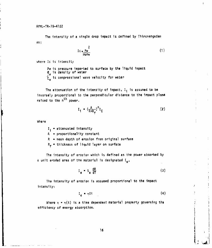
The intensity of a single drop impact is defined by Thiruvengadam
as:2
Ic. Pw (I)
where Ic is intensity
Pw is pressure imparted to surface by the liquid impacte is density of water
Cw is compresslonal wave velocity for water
The attenuation of the intensity of impact, 1i is assumed to be
inversely proportional to the perpendicular distance to the impact plane
raised to the nth power.
I Ic (2)
Where
Ii a attenuated intensity
A - proportionality constant
R - mean depth of erosion from original surface
Rf a thickness of liquid layer on surface
The Intensity of erosion which is defined as the power absorbed by
a unit eroded area of the material is designated Ie
SdR(3le a SeV (3)
The intensity of erosion is assumed proportional to the impactintensity:
Ie a n1 i (4)
Where n a n(t) is a time dependent material property governing theefficiency of energy absorption.
16
L1 1.~
AFML-TR-79-4122
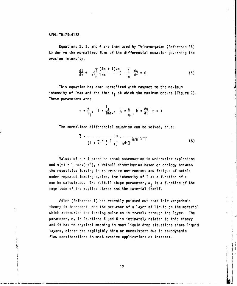
Equations 2, 3, and 4 are then used by Thiruvengadam (Reference 36)
to derive the normalized form of the differential equation governing the
erosion intensity.
dl + (2m + l)/m I d (5)S~n
This equation has been normalized with respect to the maximum
intensity of Imax and the time T, at which the maximum occurs (Figure 2).
These parameters are:
tI'C N t T . e! I ý -n F d kInil
The normalized differential equation can be solved, thus:
+ndT n/n +T (6)
n
Values of n * 2 based on shock attenuation in underwater explosions
and n(t) - 1 -exp(-t=), a Weibull distribution based on analogy between
the repetitive loading in an erosive environment and fatigue of metals
under repeated loading cycles, the intensity of I as a function of T
can be calculated. The Weibull shape parameter, a is a function of themagnitude of the applied stress and the material itself.
Adler (Reference 1) has recently pointed out that Thiruvengadam's
theory is dependent upon the presence of a layer of liquid on the materialwhich attenuates the loading pulse as it travels through the layer. The
parameter, n, in Equations 5 and 6 is intimately related to this theory
and it has no physical meaning in most liquid drop situations since liquid
layers, either are negligibly thin or nonexistent due to aerodynamicflow considerations in most erosive applications of interest.
17
AFML-TR-79-4122
Thiruvengadam's model has been generalized to cover all liquid dropimpact cases and a nomograph was generated based on cavitation data which
enabled one to estimate erosion strength and life of materials as a
function of the erosion intensity in a particular application (Figure 6).
However, it would appear that extension of the theory to liquid dropimpact requires assumptions which are removed from reality.
2. SPRINGER'S THEORY OF LIQUID IMPACT EROSION
Springer, et al (References 7, 37, 38, 39, 40), organized erosiondata from the literature and developed a theory of erosion based upon
fatigue concepts. This theory which was developed under Air Force
sponsorship was extended from monolithic materials (Reference 37), to
analyze erosion of composite materials (Reference 38), coated materials(Reference 39) and electromagnetic transmission losses in transparentmaterials (Reference 40).
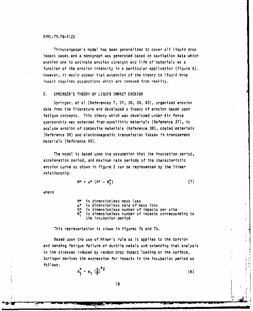
The model is based upon the assumption that the incubation period,acceleration period, and maximum rate periods of the characteristic
erosion curve as shown in Figure 2 can be represented by the linear
relationship:
M* - (N* - N*) (7)
where
M* is dimensionless mass lossa* is dimsnsionless rate of mass lossN* is dimensionless number of impacts per siteNi is dimensionless number of impacts corresponding to
the Incubation period
This representation is shown in Figures 7a and 7b.
Based upon the use of Miner's rule as it applies to the torsion
and bending fatigue failure of ductile metals and extending that analysisto the stresses induced by random drop impact loading on the surface,
Springer derives the expression for impacts in the incubation period as
follows:
NI a ()a2 (8)
18
MAL
AFML-TR-79-4122
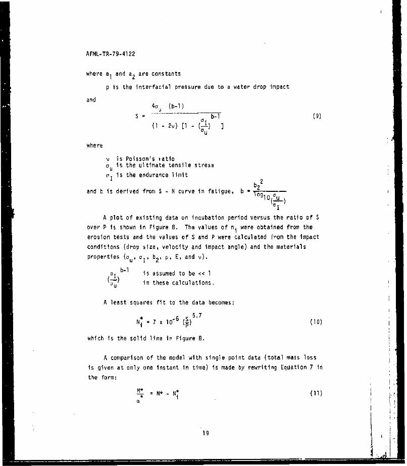
where aI and a 2 are constants
p is the interfacial pressure due to a water drop impact
and4a (b-i)
S b- (9)1I 2v ) [1 - (--)
where
i Is Poisson's ratiois the ultimate tensile stress
yI is the endurance limit
and b is derived from S - N curve in fatigue, b 2
A plot of existing data on incubation period versus the ratio of S
over P is shown in Figure 8. The values of ni were obtained from the
erosion tests and the values of S and P were calculated from the impact
conditions (drop size, velocity and impact angle) and the materials
properties (au, aI, b2 , p, E, and v).b-I1
aI b- is assumed to be << 1-(O in these calculations.
A least squares fit to the data becomes:• S 5.7
Ni= 7 x I6 (5) (10)
which is the solid line in Figure 8.
A comparison of the model with single point data (total mass loss
is given at only one instant in time) is made by rewriting Equation 7 in
the form:
M* _N I )•, - N (
1919I
AFML..TR-79-4122
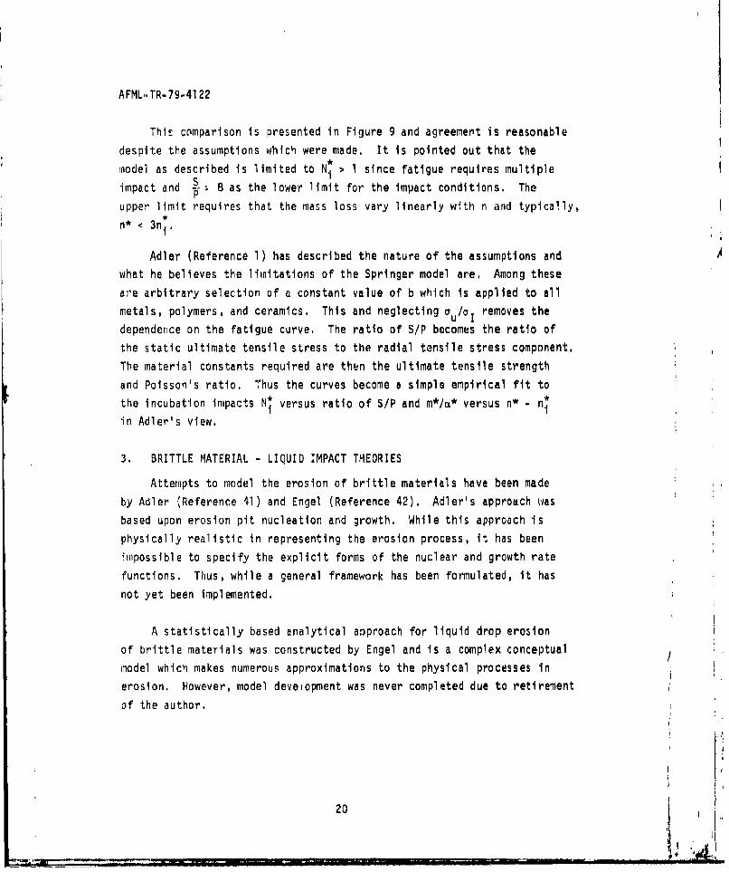
This comparison is presented in Figure 9 and agreement is reasonable
despite the assumptions which were made. It is pointed out that the
model as described is limited to Ni > I since fatigue requires multiple
impact and S , 8 as the lower limit for the impact conditions. Thep
upper limit requires that the mass loss vary linearly with n and typically,n* < 3n1 .
Adler (Reference 1) has described the nature of the assumptions and
what he believes the limitations of the Springer model are, Among these
are arbitrary selection of a constant value of b which is applied to all
metals, polymers, and ceramics, This and neglecting au/hI removes the
dependence on the fatigue curve. The ratio of S/P becomes the ratio of
the static ultimate tensile stress to the radial tensile stress component,
The material constants required are then the ultimate tensile strength
and Poisson's ratio. Thus the curves become a simple empirical fit to
the incubation impacts Ni versus ratio of S/P and m*/t* versus n* - niin Adler's view.
3. BRITTLE MATERIAL - LIQUID IMPACT THEORIES
Attempts to model the erosion of brittle materials have been made
by Adler (Reference 41) and Engel (Reference 42), Adler's approach was
based upon erosion pit nucleation and growth, While this approach is
physically realistic in representing the erosion process, it has been
impossible to specify the explicit forms of the nuclear and growth rate
functions, Thus, while a general framework has been formulated, it has
not yet been Implemented.
A statistically based analytical approach for liquid drop erosion
of brittle materials was constructed by Engel and is a complex conceptual
model which makes numerous approximations to the physical processes in
erosion. However, model deveiopment was never completed due to retirement
of the author.
20
AFML-TR-79-4122
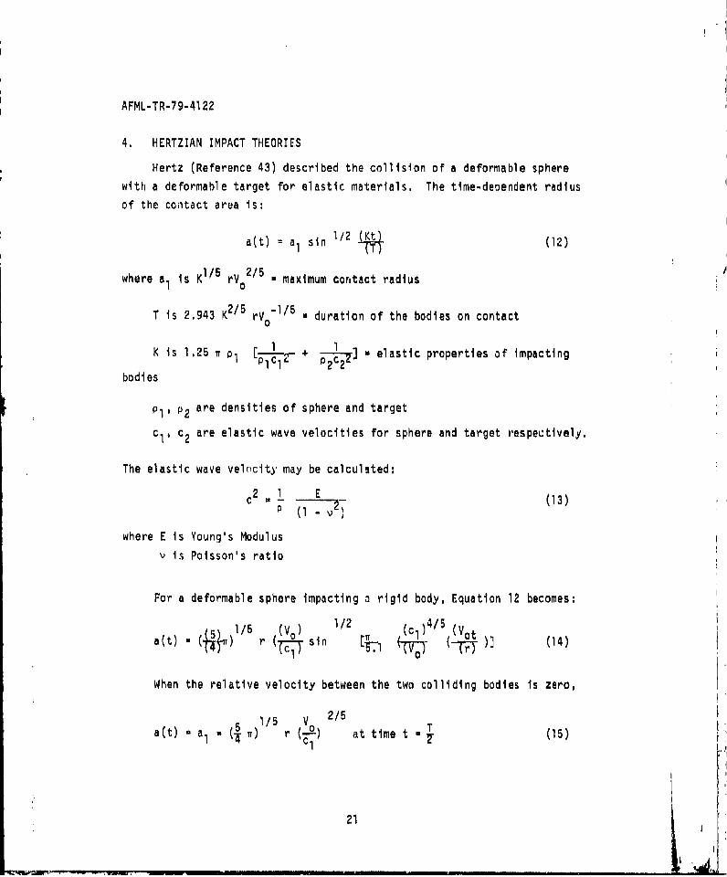
4, HERTZIAN IMPACT THEORIES
Hertz (Reference 43) described the collision of a deformable sphere
with a deformable target for elastic materials. The time-dependent radius
of the contact area is:
a(t) = a sin 1/2 (12)
where a. is K1/ 5 rVo2/ 5 . maximum contact radius
T is 2,943 K2 / 5 rV0 "1/5 . duration of the bodies on contact
is 1.25 7 1p + elastic properties of impacting
bodies
p1 , P2 are densities of sphere and target
cI, c2 are elastic wave velocities for sphere and target respectively.
The elastic wave velocity may be calculated:
C2 *1 E (13)
where E is Young's Modulus
v is Poisson's ratio
For a deformable sphere impacting a rigid body, Equation 12 becomes:
/5 ) i1/2 N c )4/5 (Vota(t) ( ) 1 ( sin 3-.1 -- (1
When the relative velocity between the two colliding bodies is zero,
1/5 Vo 2/5
a(t) - a1 1 r at time t - (15)
21
AFML-TR-79-41 22
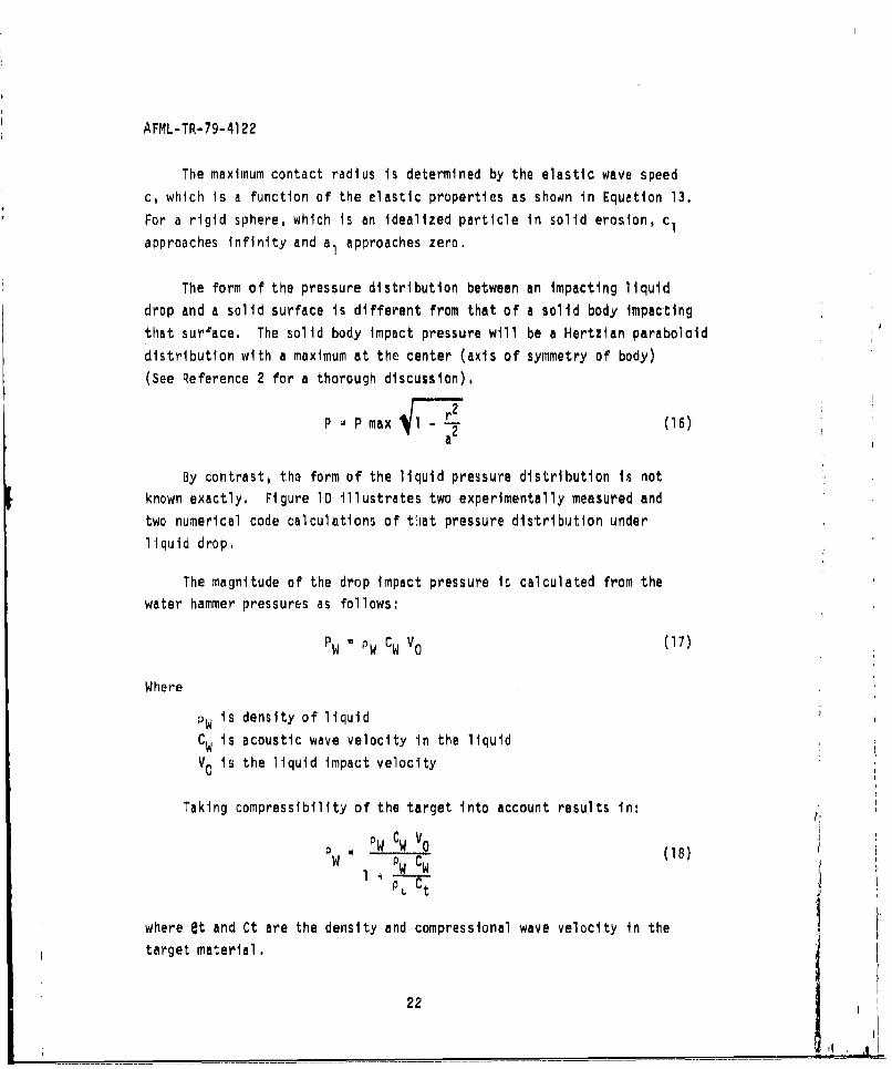
The maximum contact radius is determined by the elastic wave speedc, which is a function of the elastic properties as show~n in Equation 13.
For a rigid sphere, which is an idealized particle in solid erosion, c1approaches infinity and a I approaches zero.
The form of the pressure distribution between an impacting liquiddrop and a solid surface is different from that of a solid body impactingthat surface. The solid body impact pressure will be a Hertzian paraboloiddistribution with a maximum at the center (axis of symmetry of body)(See Reference 2 for a thorough discussion).
P AP max (16)a
By contrast, the form of the liquid pressure distribution Is notknown exactly. Figure 10 illustrates two experimentally measured andtwo numerical code calculations of that pressure distribution underliquid drop.
The magnitude of the drop impact pressure is calculated fromi thewater hammer pressures as follows:
P W 0 W CWo (17)
Where
PWis density of liquidCWis acoustic wave velocity in the liquid
V 0 is the liquid impact velocity
Taking compressibility of the target into account results in:PW. C. V
PW I P WCW (18)
where et and Ct are the density and compressional wave velocity in thetarget material.
22
AFML-TR-79-4122
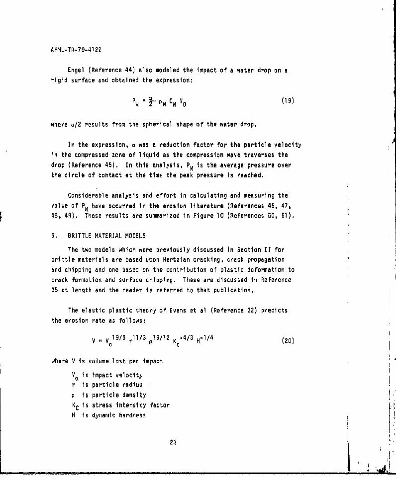
Engel (Reference 44) also modeled the impact of a water drop on a
rigid surface and obtained the expression:
P a P C Vo (19)
where a/2 results from the spherical shape of the water drop.
In the expression, a was a reduction factor for the particle velocity
In the compressed zene of liquid as the compression wave traverses the
drop (Reference 45). In this analysis, PW is the average pressure over
the circle of contact at the time the peak pressure is reached.
Considerable analysis and effort in calculating and measuring the
value of PW have occurred in the erosion literature (References 46, 47,
4B, 49). These results are summarized in Figure 10 (References 5O, 51).
5. BRITTLE MATERIAL MODELS
The two models which were previously discussed in Section II for
brittle materials are based upon Hertzian cracking, crack propagation
and chipping and one based on the contribution of plastic deformation to
crack formation and surface chipping. These are discussed in Reference
35 at length and the reader is referred to that publication.
The elastic plastic theory of Evans et al (Reference 32) predicts
the erosion rate as follows:
V - vo0l/ 6 rl/ plg/l 2 Kc- 4 / 3 H-' 4 (20)
where V Is volume lost per impact
V0 in impact velocity
r is particle radius
p is particle density
Kc is stress intensity factor
H is dynamic hardness
" !
AFML-TR-79-4122
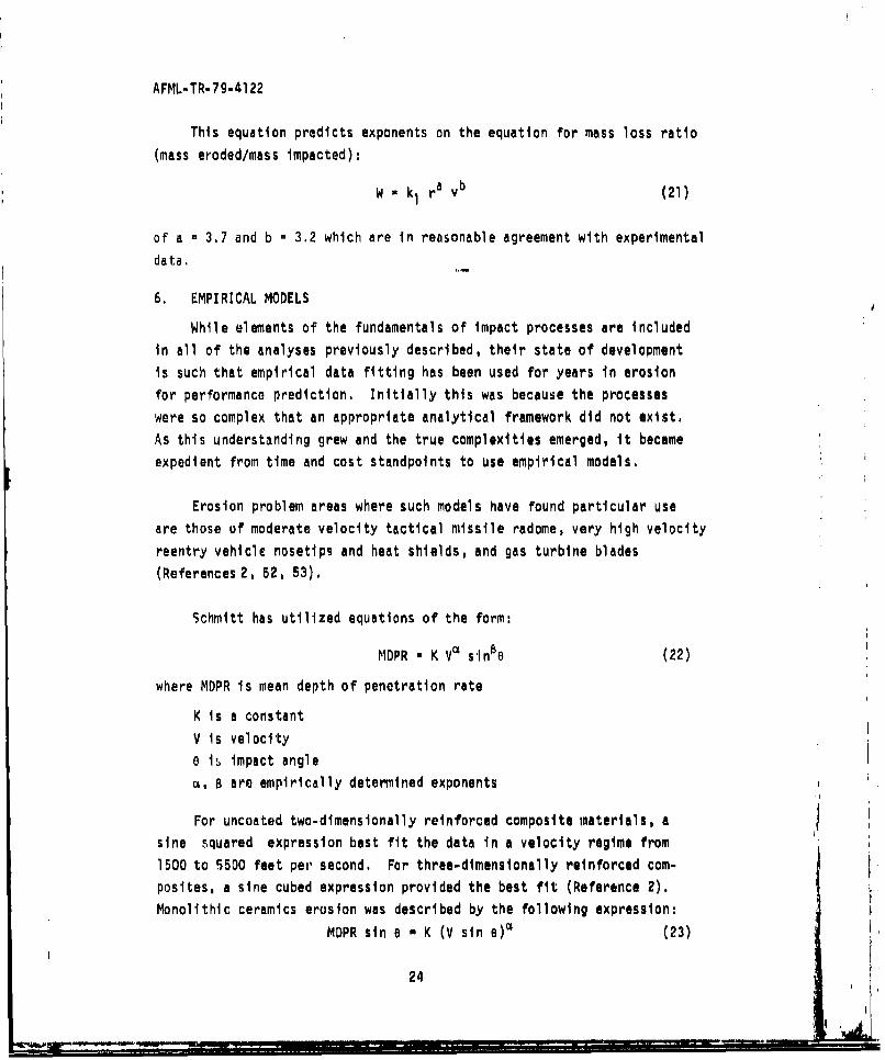
This equation predicts exponents on the equation for mass loss ratio
(mass eroded/mass impacted):
W - k1 ra vb (21)
of a - 3.7 and b - 3.2 which are in reasonable agreement with experimental
data,
6. EMPIRICAL MODELS
While elements of the fundamentals of impact processes are includedin all of the analyses previously described, their state of development
is such that empirical data fitting has been used for years in erosion
for performance prediction. Initially this was because the processes
were so complex that an appropriate analytical framework did not exist.
As this understanding grew and the true complexities emerged, it becameexpedient from time and cost standpoints to use empirical models.
Erosion problem areas where such models have found particular use
are those of moderate velocity tactical missile radome, very high velocityreentry vehicle nosetips and heat shields, and gas turbine blades
(References 2, 52, 53).
Schmitt has utilized equations of the form:
MDPR - K V• sinBe (22)
where MDPR is mean depth of penetration rate
K Is a constant
V is velocitye is impact angle
B, B are empirically determined exponents
For uncoated two-dimensionally reinforced composite materials, asine squared expression best fit the data in a velocity regime from1500 to 5500 feet per second. For three-dimensionally reinforced com-
posites, a sine cubed expression provided the best fit (Reference 2).Monolithic ceramics erosion was described by the following expression:
MDPR sin e - K (V sin e)4 (23)
24
AFML-TR-79-4122
In the expressions for ceramics, laminates and bulk plastics, the
velocity was typically the fifth to seventh power. This very high
dependence upon impact velocity for liquid impact erosion in a moderate
velocity regime has been confirmed by numerous experiments (References
54, 55).
For the carbon-carbon composites and graphites, Equation 22 with
B * 3, provided the best fit for the data in the speed regime 4000 to
5500 feet per second. Table 3 summarizes these data (Reference 2).
Extrapolation of rain erosion data from subsonic to supersonic to
hypersonic velocities has been difficult because of the changes in response
of the materials in the various velocity/temperature coupled environments.
Thus the correlations of data such as those of Schmitt have found only
limited application (Reference 56) and only then in the velocity regime
in which they were obtained.
25 H
AFML-TR-79-4122
SECTION IV
EROSION DATA SOURCES
1, LIQUID IMPACT
The rain erosion data are concentrated in the proceedings of the
four International Erosion Conferences (References 6, 8, 9, 13) and the
Special Technical Publications from symposia sponsored by ASTM Committee
G-2 on Erosion and Wear (References 2, 5, 37, 52), An excellent compilation
of multiple liquid impact erosion data may be found in Tables D-1 and D-2
of Reference 7 along with specific references to the original reports in
which these data may be found. Included are many technical reports which
are otherwise seldom cited.
The liquid impact erosion data are often presented in the form ofcurves of weight loss or erosion depth as a function of time of exposure,
Examples are shown in Figures 11 and 12 for materials exposed at 410 m/s
and a rain concentration of 10" g/m3 in the Dornier Systems GmbH rotating
arm multiple impact fac 4lity (Reference 54).
The comparative behavior of nonmetallic materials which have been
exposed to identical velocity/impact angle/erosive conditions in the AFML
rotating arm rain erosion simulation apparatus At 223 m/c is described in
References 14, 57, and 58 and at speeds of 1600 m/s from the Holloman
rocket sled rain simulation in References 2, 52, 59 and 60.
Erosion data on metallic materials may be found in the Erosion
Conference proceedings and in the Special Technical Publications previously
referenced. An important reference report on turbine blade materials
liquid impact erosion which summarized much of the existing understandinq
and data on these miterials may be found in Reference 61. Other especially
important sources of data on turbine materials are References 62 and 63.
The comparative behavior of brittle materials is described for
rotating arm tests In References 4, 64, 61,, and 66, In general, the
velocity exponents for glasses and ceramics are considerably higher
26
AFML-TR-79-41 22
(up to 13) than for metals or plastics (typically 6 to 7), Most brittle
materials have criteria for damage other than weight loss- for example,reduction in transmission through optical materials or catastrophic
fracture in supersonic radome ceramics.
2. SOLID IMPACT
The accessible data base for solid particle impact erosion of
materials is quite limited because much of the early work on metals was
considered proprietary to jet engine manufacturers and there has not
been extensive research on ceramics. It is only with the current emphasis
on erosion in energy conversion systems that widely available data are
becoming disseminated.
A recent comprehensive screening program was undertaken by Hansen
(Reference 67) using an S. S. White Abrasive Unit for impacting over
200 materials with 27 micron alumina particles at velocities of 170 m/sat room temperature (20 0C) and elevated (700 0C) temperatures. Impingement
angle was 90 degrees. Figures 13 and 14, which are taken from Reference
67, show the relative ranking of metals and ceramics normalized to the
resistance of Haynes Stellite 6B, which is a widely used erosion resistant
alloy. Similar rankings are shown inTables 4 and 5 which identify the
materials,
Conclusions from these data are that imprcvement over Stellite 6B
was at best 30 percent for any of the metals either at room temperatureor 7000C. Furthermore, similar rankings were obtained with increased
erosion volumes at a 20 degree Impingement angle where the erosion wouldbe maximized in ductile materials. Molydenum and tungsten were exceptions
with improved resistance of a factor of two or more under all conditions,
The ceramic materials (Figure 14) and some cermets (Figure 15)
exhibited reldtive performance which varied from several times as erosion
prone as Stellite 6B: to a factor of three to five better at room tempera-
ture. This relative 'improvement was somewhat greater at 700 0 C, as might
be expected. Several materials such as cubic boron nitride and diamond
27
AFML-TR-79-4122
exhibited no weight loss at all at either temperature. More practicalceramics such as silicon nitride, silicon carbide, zirconium diboride-tungsten carbide-alumina mixtures and boron carbide, which were hot pressedor pressed and sintered, gave improved erosion resistance compared to theStellite 6B. The ceramic results were very dependent on density and
porosity.
Excellent results were also obtained with coatings of chemical vapordeposited silicon carbide, diffused tungsten carbide and especially
electrodeposited titanium diboride. Results are summarized in Tables 6and 7 for these coatings. Thicknesses of 50 to 80 microns were requiredto achieve erosion resistance and the 700 0 C tests demonstrated the need
for thermal expansion match between the coating and substrate.
Data on metallic engine alloys including 2024 aluminum, titanium-6A1-4V, 410 stainless steel and 17-7PH steel may be found in References27 and 68. A variety of dust types (including alumina, silica-rich
Arizona Road Dust, and laetrite particles) was employed.
Tilly and Sage (Reference 69) obtained data on metal, plastics andceramics as a function of impacting velocity, particle size and type andimpingement angle. Similar data were obtained by Sheldon (Reference 70)on ceramics and metals.
The recent work of Tabakoff and co-workers (References 71, 72) haveincluded the effects of aerodynamic flow and temperature with solid
particle erosion of gas turbine materials. They have determined a velocitydependence of 3,8 for the exponent which is considerably greater thanearlier research had indicated,
28
AFML-TR-79-4122
SECTION V
MATERIALS PROPERTIES EFFECTS
Materials developers concerned with combatting erosion by developing
materials with improved liquid and solid particle erosion resistance havelong been searching for appropriate materials properties with which to
correlate erosion resistance. The hope is to discover a simple materials
property or group of properties to maximize to provide this improvement,
To date, no satisfactory simple correlation has been found because most
materials hardness or strength properties are measured at loading rates
which are not representative of those in impact situations and hence are
not indicative of the controlling behavior of the material.
1. METALS
Attempts to provide correlations with material hardness (References22, 28, for example) have been at best moderately successful. Changes inthe condition of the surface under repeated impact have the effect of
work hardening or deforming the surface so that the original surfacehardness has little controlling effect on the erosion process. See
Reference 73 for a discussion,
Numerous correlations have been attempted with strain energy pro-
perties and some success has been achieved by Thiruvengadam (Reference 74),Hobbs (Reference 75) and others. However, there are exceptions to this,
particularly with Stellite 6B, which has exceptional erosion resistance
but only moderate strain energy based on tensile tests,
Gould (Reference 76) demonstrated that the exceptional erosion
resistance of Stellite 6B cobalt-chromium alloy was due to the ability
of its cobalt base matrix to absorb energy in undergoing a strain-induced
phase transformation fiun face centered cubic to hexagonal close packedstructure. The erosion resistance was also shown to be independent of
hardness or grain size. Therefore, it appears that the strain energy
properties provide at least one clue to developing improved materials,
29
AFML-TR-79-4122
Other correlations (Reference 29) with thermal properties such as
thermal expansion coefficients, specific heat, temperature rise required
for melting, melting point, etc. have been developed, but a clear cut
correlation is not evident,
2. POLYMERS
Development of polymeric coatings, romposites and bulk plastics with
erosion resistance has concentrated on elastomeric coatings for rain
erosion resistance and assessment of plastics behavior, Correlations with
properties have been minimal because the rotating arm apparatus (Figure 6)
provides a direct simulation of the actual rain encounter (except for
centrifugal force effects) and success has been achi,4ved in improved
polyurethane and fluorocarbon coatings by doing ranking and development
with the rotating arm. Correlations between rotating arm ranking and
actual flight exposures have been obtained (Reference 77) and the performance
of improved materials in actual service has further confirmed the use of
this apparatus (Reference 78).
Conn and Thiruvengadam (Reference 79) utilized a split Hopkinson
pressure bar apparatus to study the dynamic stress-strain characteristics
of elastomeric rain erosion resistant coatings. This apparatus provided
strain rates of lO4 sec-i which approached the loading rate in an actual
drop impact. Considerable controversy ensued over utilization of the
apparatus because of the assumptions associated with uniaxial stress for
a drop impact on which 'Its use was predicated (Reference 13), No direct
correlation between strain rate properties and' erosion resistance was de-termined in these studies,
Oberst (Reference 80) described the erosion of bulk nolymers asrelated to their notch impact strength and found a general correlation
between the two. However, scatter in values of notch impact strength
and other complications in the experiments (performed at Durnier) such
as temperature rises prevented a definitive correlation.
30
AFML-TR-79-4122
3. CERAMICS
The plastic deformation observed in ceramics at elevated temperatures
and/or low impact angles is particularly important and results in residual
stresses which can cause crack formation and chipping (Reference 35).
This behavior is governed by the dynamic hardness (hardnesses measured
under impulse loading) and the critical stress intensity factor of the
material. The ductile-to-brittle transition of ceramics is determined
by the behavior of these variables as a function of temperature but tests
have indicated the critical stress intensity factor of ceramics is not
dependent on temperature. There is also indication that dynamic hardness
may beindependentat least for short times (less than 10-4 sec). The
ability of the elastic-plastic theories to predict ceramics erosion
indicates that the dynamic toughness which governs those elastic-plastic
processes is a critical property for these materials,
The influence of density and porosity on the liquid impact erosion
of reaction sintered silicon nitrides has been described by Schmitt
(Reference 81). He determined that a tradeoff could be made between
maximizing density/minimizing porosity (which resulted in minimum surface
erosion and increased in-depth cracking) and intermediate density/porosity,
where strength properties were sufficient for structural purposes and
surface erosion was acceptably moderate while cracking was eliminated.
It appears that for certain ceramics the porosity can be tailored to
cause crack arrest in severe erosive exposures (in these tests, which
were Mach 4 velocity rain impacts).
Other experiments by Schmitt (Reference 82) on most state-of-the-art
ceramics showed that some monolithic materials (alumina, boryllia, hot
pressed silicon nitride) which had extremely high strength properties
would survive a 1600 m/s multiple impact exposure with no damage, Still
others (Pyroceram, cordierite, slip cast fused silica) exhibited massive
fracture, particularly at higher impact angles.
31
AFML-TR-79-4122
Thus, it can be concluded that for the above classes of materials,no simple set of materials properties can be optimized for erosion re-sistance. Dynamic properties at strain rates comparable to impactloading are the keys to erosion performance. For these rtasons empiri-
cal determination of erosion resistance and extensive screening and
relative ranking of materials have proven to be cost-effective ways ofdeveloping materials, particul&rly for multiple impact erosion environ-ments. Studies of other properties which would be expected to influence
erosion resistance such as grain orientation, size and toughness, havenot been conducted as yet.
32
AFML-TR-79-4122
SECTION VI
MATERIALS TO RESIST EROSION
The resistance of materials to liquid drop and solid particle impact
erosion has been determined experimentally with ranking of materials asa major output of these determinations, Due to the complexity of the
erosive processes, particularly in multiple impingement, this approach
has proven cost effective because actual field experience has confirmed
the improved performance of these materials.
1. METALS
Liquid drop impact in large steam turbines led the manufacturers ofsuch equipment to screen and rank metals for erosion resistance. Thin
coatings were avoided because of very long life continuous operating
conditions which dictated reliance on inherent materials characteristics
rather than on a thin protective layer.
These screening tests led to the selection of Stellite 6B alloy
applied as protective leading edge shields or as bulk material, Service
experience proved that the Stellite 6B combatted the problem so effectivelythat the steam turbine manufacturers were able to de-emphasize research
for new erosion resistant blade materials. A case history of thismaterial development may be found in Reference 20.
For helicopter main rotor blades operating in dusty or sandy un-improved areas, the solid particle impact damage was sufficiently severe
that dynamic operation of the blade became unstable due to pitting androughness on the leading edge perturbing the aerodynamics. After con-siderable development, the use of electroplated nickel, which had been
pioneered for liquid impact erosion protection by Weaver (Reference 83),was adopted for rotor blade protection. The nickel was applied either
as an electroformed nickel sheath adhesively bonded, or fastcned to thealuminum rotor blade, or plated onto a stainless steel sheath which was Kthen fastened to the rotor leading edge.
3333I
-it
AFML-TR-79-4122
This system or some variation of it is still the state-of-the-art
for rotor blade erosion protection including that for advanced composite
graphite epoxy or Kevlar-epoxy constructions. Because of weight require-
ments, the metal is used only on the high impact angle and severe exposure
areas, while the remainder of the blade is coated with elastomeric
polyurethane.
The polyurethane alone as a protective coating was investigated but
did not provide sufficient long term resistance to severe particle impact
environmentsl hence, it has only been used in low impact angle surfaces.
The selection of metals and metal alloys for gas turbine vanes and
blades has traditionally been based on mechanical strength properties,
fatigue resistance, and creep resistance in rotating dynamic environments.
Tolerances are typically extremely tight and allowances for erosion
protective measures are minimal. As a result, thin chemical vapor deposited
or sputtered coatings have been investigated. Titanium carbon-nitride,
titanium diborido, ferric boride, and other coatings have been attempted
with limited success because of thickness limitations, deposition parameters
which adversely affected fatigue life, corrosion resistance reduction due
to galvanic action between coating and substrate, or application cost.
Sputtering (Reference 84) offers one methnd for application which does
not adversely affect the substrate; silicon carbide and tungsten carbide
sputtered coatings have demonstreted some promise.
Titanium diboride (Reference 67) hab exhibited excellent resistance
to solid particle impact although it has not been optimized for Jet engine
applications.
2. CERAMICS
Impact erosion or ceramic materials has concentrated on rain erosion
effects on tactical missile radome materials at high velocities until
recently when solid particle erosion on refractory liners, runway debris
on optical missile domes, and the desire to use ceramics in turbine
engines to increase performance has led to consideration of such effects.
34 I
AFML-TR-79-4122
A summary of recent efforts to understand mechanisms of solid particleimpact and analytically model those effects may be found In Reference 35.
As discussed in Section V, the use of reramics with resistance toliquid impact has been limited because additional requirements for thermal
shock resistance, fabricability, and lower cost have dictated the use of
slip cast fused silica and pyroceram for missile radomes,
Recent research and development has explored reaction sintered andhot pressed silicon nitride for such applications, but the apparentsensitivity of these materials to surface flaw distribution has rendered
their utility somewhat suspect. Fiber reinforced ceramic constructionssuch as silica with colloidal silica matrix, silica with ethyl silicate
matrix, and alumina fabric with alumina matrix have also been evaluatedbut severe surface erosion was experienced even though catastrophic
fracture did not occur (Reference 60).
Th,. .'eamlc coatings have been utilized for composite radome con-
struction proticction with limited success (Reference 19), The key toutilization was maximizing the fnrgiveability of the coating to theimpact so that it did not spall or fracture off due to coating-substrate
impedance mismatch. A slip cast alumina shell adhesively bonded to glass-polyimide laminate withstood a Mach 3 multiple rain exposure whileoptimized plasma-sprayed coatings did not survive the test. Surfaceerosion was observed on the slip cast alumina but it did survive.
Solid particle erosion resistance of numerous refractory materials,ceramics, and cermets has been determined by Hansen (Reference 67).
Materials such as boron carbide, tungsten carbide, silicon carbide,silicon nitride, and titanium diboride were found to have more than four
times the erosion resistance of metals such as Stellite 6B and 304 and316 stainless steel. Cubic boron nitride and Industrial diamonds werefound to not erode at all.
35
AFML-TR-79-4122
The use of ceramics for many large scale applications is of course
dictated by economies of manufacture, installation, and maintenance.
Discussion of these implications can be found in Reference 20.
3. ELASTOMERS
One of the most effective ways of combatting li'quid impact erosion
effects on reinforced plastic composites In aircraft has been the use of
elastomeric coatings of thicknesses 0.2 mm to 0.3 mm (0,008 to 0.012
inches) (References 19, 77). These materials have been developed for
aircraft radome protection to have combinations of rain erosion resistance,
antistatic properties for reduction of precipitation static buildup on
plastic surfaces, dielectric transmission for radar and other electro-
magnetic radiation, thermal flash resistance for protection from ther-
monuclear burst thermal pulse and room temperature curing, and spray
application characteristics.
Coatings based upon neoprene rubber, which were developed in the
early 1950's, have been superseded as the state-of-the-art by moisture
curing and two component polyurethane continii. The polyurethane coatings
have proven to have greater erosion resistance,improved weathering
characteristics, and much longer life in service than the neoprenes.
In addition, a class of coatings based upon fluorocarbon elastomers
has also been developed which possesses long-term high temperature (2600C)
capability and extremely good weatherability while maintaining the com-
binations of properties previously mentioned.
Solid particle erosion tests of these polyurethane and fluorocarbon
coatings have demonstrated limited capability; however, the fluorocarbnn
coatings have shown sand erosion resistance at temperatures of 5008F in
short duration exposures.
36
AFML-TR-79-4122
Tests on other elastomeric materials such as silicones have demon.
strated no liquid impact erosicn resistance due to the lack of tearresistance and inability to withstand the repeated deformations underdrop impingement. By contrast, the polyurethane and fluorocarbon elasto-
meric coatings have high 01ongation, low modulus and moderate tensilestrengths, and withstand impact for protracted periods.
The development of these coatings has been empirically based becausethe rotating arm simulation apparatus on which they have been testedprovides a very close simulatio, of the subsonic rain impact conditions
to which they are exposed and correlations have bean developed between
the modes of failure and relative rankings of materials in this apparatus
and the actual performance in flight exposures.
4. PLASTICS
The erosion resistance of monolithic and reinforced plastics hasbeen determined as a baseline substrate material which must be protectedfrom liquid and solid impact. Only in a few isolated instances, i.e.,protective covers for certain electrnmagnetic antennas, have these
plastics been considered as erosion protective materials themselves
(Reference 14).
Thermoplastic polymers such as nylon, acetal, polyethylene, and
polyphenylene oxide have provided resistance to rain drop impact;although their application has been limited because of thermal andstrength inadequacies.
Tests of reinforced composites have shown that chopped fiber rein-
forcement provides less erosion resistance than cloth reinforcement andthat only by resorting to unusual construction, such as all fibersoriented end-on to the surface being impacted, could any significanterosion resistance be achieved. These unusual constructions are typically
impractical because of lack of structural properties.
37
IhI
AFML-TR-79-4122
SECTION VII
DESIGN TECHNIQIIES TO AVOID EROSION
The design methodology for avoiding erosion in impact situations is
not well developed because, with the exception of some aerospace systems
or components, erosion has typically been an after-the-fact occurrence
or other requirements have dictated the configuration, choice of materials,
or constraints on erosion prevention measures.
1. REDUCTION IN VELOCITY
As p.reviously discussed, the velocity of impact is the most Important
variable in governing the severity of erosion and the most important
influence on erosion rate. However, increased velocity is almost always
desired whether It is aircraft and missile flight capability, turbine
engine fan speed for efficiency, movement of coal particles in energy
conversion processes or velocity of steam turbine generator blades.
Redesign of equipment to reduce the speed at which Impacting drops
or particles strike eroding surfaces should be accomplished whenever
possible to reduce the velocity below the erosion threshold velocity.
2. REDUCTION IN IMPACT ANGLE
The variation of erosion rate in liquid impact depends upon the
sine squared of the angle for composite laminates (Reference 52) and the
sine cubed of the angle for 3-dimensionally reinforced carbon composites
(Reference 2). Since most of the erosion processes are governed by the
pressure loading as developed from the normal component of the velocity
vector (V sin 0), reduction in the impdct angle is perhaps the most
effective design method for mitigating erosion effects in liquid impact.
The erosion rate varies with the angle for solid pdrticle impact
with ductile materials showing a maximum rate at 20-30 degrees and brittle
materials showing a maximum for 90-degree impact. Therefore, depending
upon the types of materials being protected, an impact angle selection
and design must be based accordingly.
Angles of 15 degrees or less will usually minimize erosion.
38
AFML-TR-79-4122
3. REDUCTION IN DROPLET SIZE OR PARTICLE DIAMETER
The influence of droplet or particle size on erosion is a minor butimportant one. The smaller the drops or solid particles are, the less
damage will be experienced.
One technique which Is most appropriate is utilization of shock layer
shattering and breaking up of rain drops to mitigate tho impact damage
by fragmenting the drops into very small pieces which do not damage aft
surfaces at supersonic speeds. This phenomenon has been the subject ofnumerous papers and sessions at international erosion conferences and
the knowledge on the subject is summarized in References 86 and 86..
The shock layer protection has been extended to optical domes andeven to certain cone shapes by use of tapered cylindrical covers over
the optical domes or wide annular rings at the base of the cones, The
shock layer attached to these fixtures provides sufficient distance
from the shock to the surface to enable shattering to occur, Obviously
these techniques apply primarily to liquid impact supersonically, as the
shock layer will have no effect on solid particles and even deflectionwill be minimized (References 87, 88).
4. PARTICLE CONCENTRATION REDUCTION
Since the erosion is directly proportional to the number of particles
being struck, the elimination or reduction of significant numbers of
particles is desired for protection of surfaces and components.
Liquid impact has caused speculation for debris layer shielding of
materials due to impacted water layer and/or target debris on the surface,
This would reduce erosion since that layer would absorb considerable
energy of impact and reduce the loads delivered to the material surface.
However, some evidence exists for little or no effects of this layer
(Reference 89) and others for some measurable shielding provided by this
layer.
39 , t
AFML-TR-79-4122
Solid particle centrifugal separators have been used on helicopter
engines for reducing the concentration of particles ingested into the
inlet, Although these separators result in performance penalties, they
are successful in prolonging the life of engine blades operating industy environments. Similar techniques may likely be required for direct
gasification in coal energy systems,
5. LEADING EDGE RADIUS EFFECTS
lThe sharpness of the leading edge in turbine blades, aircraft air-
foils, or other forward facing surfaces has an interesting effect onliquid impact erosion, Although no quantitative studies have been done,
many investigators have observed that erosion is aggravated when the
leading edge radius is reduced so that the dimensions of the edge are A
similar to or less than the impacting drops. The concentration of
stresses under the impact loading aggravates damage while in a blunter
shape, these stresses are dissipated with correspondingly less damage,
The only method known to reduce these effects 'Is to make saw teethin the knife edge. Experiments at the Air Force Materials Laboratory on
composite knife edge specimens showed that sizting of the tooth point-to-point spacing versus depth could be optimized to cause significant
reduction in erosion (Reference 90), No such effects of leading edgeradius are known in solid particle erosion.
6. FLUSH MOUNTING/GRADUAL BENDSThe impact of liquid drops on surfaces shows that preferential
attack will occur at any discontinuity in the surface, even though the
two sides of the seam are flush mounted. This occurs In high speed 1liquid impact but has also been observed in low speed rotating arm tests.
The design of radomes with very slender ogival or conical shapes
(for drag purposes) has typically employed a sharp pointed metal cone
for erosion protection in the 90-degree impact area. However, it has Hbeen essential to include a conical base diameter of the metal which
slightly extends beyond the outer radius of the ceramic tip to prevent
40
AFML-TR-79-4122
attack of the ceramic at that edge with fracture and potential loss ofthe tip,
Flush mounting is desired since major discontinuities will beimmediately attacked. However, any holes (for example, the back edge ofa Phillips head slot in a bolt) which are oriented perpendicular to theflowing drop can be attacked.
Similar results have been experienced for misaligned pipe carryingflowing solid particles either entrained In a gas or in a liquid slurry,The preferential attack has caused failures as the edges are eroded andwidened. Extremely careful alignment and mtnimizatioh of discrepanciesat weld joints are the guidelines to be followed,
Another aspect of this problem is the desirability of large radiusbends In pipe or ducting carrying solid particles to avoid erosion atelbows, Since the impact velocity of the particles against the surfacegoverns the erosion, reduction of that velocity by a gradual curvaturewhich minimizes normal impact can provide change In particle directionwithout the serious erosion otherwise experienced,
Another technique is a dead tee where the particles build up in theblocked end of a tee and then conform to flow streamlines so that particleschanging directions Impact other particles rather than the walls of thetube or pipe.
7. GEOMETRY AND SCALE-UP
The methodology for assessing full size geometry and scale-up effectsfor erosion has not been developed. Typically, small simple specimenshapes ore used for erosion testing and estimates are then made of effectsto be anticipated on a large scale.
41
AFML-TR-79-4122
In the case of ceramics for tactical missile radomes, the proof ofthe erosion resistance of a particular material can only be proven by
fabrication of a piece of prototype hardware which has realistic attach-ment fixtures and testing it in a simulated rain environment (such as
a prototype radome propelled through the rainfield on a rocket sled atHolloman AFB).
d
Similar cunsiderations apply to ceramics for large scale equipment
in coal conversion plants, metals in combined corrosive erosive
environments, and numerous other situations. Attempts to describe and
predict effects in large scale equipment are becoming more available inliterature (References 20, 53).
42
AFML-TR-7g-41 22
SECTION VIII
CONCLUSIONS
The science of liquid and solid impact erosion is growing rapidly,
The vast quantities of empirical and screening data which have providedrankings of performance of materials and the basis for selection of
erosion resistant materials are now being supplemented with analyticalmodels and mechanistic understanding for Improved analysis of erosion
processes.
The guidelines for improved erosion resistance inmaterials which
have been obtained through experimental testing havn been successful In
developing better materials. However, the methodology for predicting
In-service performane and the lifetime of materials in erosive environ-ments is still In tIs infancy. Careful review of past experience with
materials approaches, design techniques, and practical protective methodscan enable selection and design of erosion resistant cnmponents and
structures.
43
AFML-TrR- 79-4122
REFERENCES
1. W. F. Adler, "The Mechanics of Liquid Impact", Treitisn onMaterials Science and Technology, Vol. 16, Academic Pre-sTg -
2. G. F. Schmitt, "Influence of Materials Construction Var 4-,bles (,nthe Rain Erosion Performance of Carbon-Carbon Composites,'" Erosion;Prevention and Useful Applications, ASTM-STP-664, W. F. Adler, ed.American Society for Tstingand aterials, 1979, pp. 374'-405.
3. W. F. Adler and S, V. Hooker, "Rain Erosion Mechanisms in BrittleMaterials," Wear, 60 1978, pp 11-38.
4. T. L. Peterson, "Multi le Water Drop Impact Damage in LayeredInfrared Transparent Materials", Erosion: Prevention and UsefulApplications, ASTM-STP-664, W, F, Adler Ed,, American Society for"Testing and Materials, 1979, pp. 279-297.
5, D, J. Beckwith and J, B. Marriott, "Water Jet Impact Damage in aCobalt-Chromium-Tungsten Alloy", Erosion .b Cavitationor Impingement,ASTM-STP-408, American Society for Testing and Materials, 1967, pp. 111-124,
6. F. J. Heymann, "A Survey of Clues to the Relationship betweenErosion Rate and Impact Parameters", Proceedings of the Second MeersburgConference on Rain Erosion and Allied Phenomena, A, A. Fyall andW B King, Eds., Royal Aircraft EsHtfblsm•e•ntFarnborough, England,1967, pp. 264.
7. G. S. Springer, Erosion by Liquidj Ipact, Scripta PublishingCompany, John Wiley & SonsWnagstoi, DC, 76, pp. 264.
8. W. F. Adler and R. F. Vyhnal, "Rain Erosion of Ti-A1-4,"Proceedings of the Fourth International Conference on Rain Erosion andA-ssoctePhenomena, A. A. Fyall and R, B., kingT 's.,'RoTyal AircraftEstablishment, Far'nborough, England, 1974, pp. 539-569.
9, H. Rieger, "The Damage to Metals on High Speed Impact with WaterDrops," Proceedings of the Rain Erosion Conference Held at Meersburg,West, Germany, A. A. Fyall and R, B. King, Eds., Royal AircraftEstablishment, Farnborough, England, 1965, pp. 107-113,
10, "Standard Terminology Relating to Erosion and Wear, ASTM StandardG40-77, American Society for Testing and Materials 197B Annual Book ofStandards, Philadelphia, PA Part 10, pp. 827-833.
11. A. Thiruvengadam, "The Concept of Erosion Strength," Erosion byCavitation or Impingement, ASTM-STP-4D8, American Society for Test"and Materials, 6', pp'. 22.35b.
12. W. F. Adler and S. V. Hooker, Characterization of TransparentMaterials for Erosion Resistance, AFMF-TR-76-16, Ai7r Force Ma TrTTsLaBoratory, Wright-Patterson Air Force Base, Ohio, 1976.
44
AFML-TR-79-41 22
REFERENCES (Cont'd)
13. G. F, Schmitt, "The Erosion Behavior of Polymeric Coatings andComposites at Subsonic Velocities," Proceedlpks of Third InternationalConference on Rain Erosion and Associaid;WenMomena, A. A. Fyall andR. B3. King; Ed s7T1Xo~y~a1r r1Era-tTF-stiS~is hment, Farnborough, EnglIand,1970, pp. 107-128.
14, G. F, Schmitt, "Materials Parameters that Govern the ErosionBehavior of Polymeric Composites In Rain Environments," SCorn ositeMaterials: Testing and Oppign (Third Conference), AS TM-S1P54Aime-rican Society for Testing and Materials, 1974, pp. 303-323.
15, 0. A, Gorhamn, M. J, Matthewson~and J. E. Field, "Damage Mechanismsin Polymers and Composites Under High-Velocity Liquid Impact," Erosion-,Prevention and UsflADOlications, ASTM-STP-664, American Society -7-'Testing aM MRatesf-1079, pp. 320-342.
16. G. F. Schmitt, "Polyurethane Coatings for Rain Erosion Protection,"Pr~eedngsof the Second Meersburg Conference on Rain Erosion and
Allied P1enomenk, ATT,7 i and R. B. Kig a. oylArcFEi~shmoii-nYt-arnborough, England, 1967, pp. 329-357.
17. H. Rieger and H. Boche, "Erosion Behavior of Surface Coatings,"Proceedinfgs of the Fourth ____ntin Conference on Rain Erosion and_WOO&i ed Phenomena, *A. . ya1 1 an .. King, Eds,, Royal ARcrfE~stabl ishmnt arnborough, England, 1974, pp. 637-675.
18. G. F. Schmitt, "Elevated Temperature Resistant, Subsonic RainErosion Resistant Fluoroelastorner Radome Coatings," ____ dngsof theThird International Conference on Electromagnetic Windows, Paris, France,§75, p,211 2
19. G. F. Schmitt, "Advanced Rain Erosion Resistant Coating Materials,"Science of Advanced Materials and Process Engineering Series, Vol. 18,
20. Er'osion Control in Energy Systems, NMAB-334, National MaterialsAdvisory Board, National Academy of Science, Nov. 1977, pp. 228.
21. L, K. Ives and A. W. Ruff, "Electron Microscopy Study of ErosionDamage in Copper," Erosion: Prvninand Useful AR lications, ASTMSTP-664, W. F. AlTEdAeiaSoetfor Testing an&1ai erials,1979, pp. 5-35.
22, 1. Finnie, A. Levy,and D. H. McFadden, "Fundamental Mechanisms ofthe Erosive Wear of Ductile Metals b~y Solid Particles," Erosion: Pre-vention and Useful Applications, ASTM-STP-664, W. -.Ale, -dAm-TE-anSociety for Testing and Mraterials, 1979, pp. 36-58.
23, 1. Hutchings, "Mechanisms of the Erosion of Metals by Solid Pnrtirles,"Ibid. pp 59-76.
46
AFML-TR-79-4'122
REFERENCES (Cont'd)
24. J. Mail and 0. L. Sheldon, "Mechanisms of Erosion of a DuctileMaterial by Solid Particles," Ibid, pp. 136-147.
25. J. G. A. Bitter, Wear, Vol. 6, 1963, pp. 5-21 and pp. 169-190.
26. G. P. Tilly, Wear, Vol. 14, 1969, pp. 63-79 and pp. 241-248; Vol. 16,1970, pp 447-465 an-'"ol. 23, 1973, pp. 87-96.
27, C. C. Smeltzer, M, F., Gulden,and W. A. Compton, Tran3actions ofASME, Vol. 92, 1970, pp. 639-654.
28, G. L. Sheldon and A. Kanhere, Wear, Vol, 21, 1972, pp. 195-209,
29. P, Ascarelli, Relations Between the Erosion by Solid Particles andthe Physical Properties of Metals, AMMRC-TR-71-47, Army Materials and
anics Researc center, Wat-Fetown, MA, 1971.
30. W. F. Adler, Analysis of Multiple Particle Impacts on BrittleMaterials, AFML-TR-74-170, Air Force Materials Laboratory, Wright-Fat-ter-so'' Air Force Base, Ohio, 1974.
31. P, A. Engle, Impact Wear of Materials, Elsevier Scientific PublishingCompany, Amsterdam, 1076, ppCh333 -apters 4 and 5).
32. A. G. Evans, M. E. Gulden, G. E. Eggum,and M. Rosenblatt, actDamage in Brittle Materials in the Platc Response Regime. Contract No.OO014-75-.-oo6g, Report No. C5023.R, Rockwel EIn aiTonal ScienceCenter, Thousand Oaks, CA, 1976.
33. M. E. Gulden, "Solid Particle Erosion of High Technology Ceramics(Si3 N4 , Glass-Bonded A12 03, and MgF 2 ),1 Erosion: Prevention and Useful
Applications, ASTM-STP-664, W. F. Adler, Ed., American Society for Testingand Materials, 1979, pp. 101-122,
34. A. G. Evans and T. R. Wilshaw, "Dynamic Solid Particle Damage inBrittle Materials: An Appraisal," J, Materials Science, 12, 1977, p. 97,
35. A. W. Ruff and S, M. Wiederhorn, Erosion by Solid Partic1i-Iact,NBSIR 78-1575. National Bureau of Standard Interim Report, Januar7TT79,AD No. A066-525.
36. A. Thiruvengadam, "Theory of Erosion," Proceedings of SecondMeersburg Conference on Rain Erosion and Allie.dPhenomena, A. A. ryall,and R. .King, Eds., Royal Aircraft tstab's''ent, Farnborough, England,1967, pp. 605-649.
37. C. S. Springer and C. B. Baxi, "A Model for Rain Erosion of Homo-geneous Materials," Erosion Wear and Interfaces with Corrosion, ASTM-STP-567, American Society for Te3ting and Materials, 1974, pp. 1o6-127,
46
AFML-TR-79-4122
REFERENCES (Cont'd)
38. G. S. Springer and C. I. Yang, "A Model for the Rain Erosion ofFiber Reinforced Composites," AIAA Journal, 13, 1975, pp. 887-883.
39. G. S. Springer, C. I. Yanqand P. S. Larsen, "Rain Erosion ofCoated Composites," Journal of Composite Materials, 8, 1974, pp. 229-250.
40. G. S. Springer and C. I. Yang, "Optical Transmission Losses ofMaterials due to Repeated Impacts of Liquid Droplets," AIAA Journal,1975, pp. 1483-1487.
41. W. F. Adler, Wear, 37, 1976; pp. 345-352.
42. 0. G. Engel, A Model for Multiple Drop Impact Erosion of BrittleMaterials, General Electric Report GESP-610, 1971.
43. H. Hertz, Miscellaneous Papers, MacMillan and Company, London, 1886,
44. 0. G. Enqel, Mechanisms of Rain Erosion Part I. Impact Pressurein Solid-Liquid Sphere Collisions, WADC-TR-53-192, Part I, Wright AirDevelopment Center, Wright-Patterson Air Force Base, Ohio, 1953.
45. 0. G. Engel, J. Research NBS, 64A, 1960, pp. 49/-498.
46. F. J. Heymann, Erosion by Cavitation, Liquid Impingement and SolidImpingement - A Review, Westinghouse E-lectri Corp. Eng Report E-1460,
47. Y. Huang, Numerical Studies of Unsteady Two Dimensional LiquidImpact Phenomena,1W Thesis, University of Mfc-Tigan, Ann Arbor, 1971.
48. J. B. Hwang, The Impact Between a Liquid Drop and an Elastic HalfSpace," PHD Thesis, University of Michigan, Ann Arbor, 1975.
49. 1.1. Rosenblatt, L. A. DeAngelo, F. E. Eggum,and K. N. Krevenhagen,Numerical Investigtions of Water Drop Erosion Me-hanisms in InfraredTransparent Materials, AFML-TR-76-193, Air Force Naterials Laboratory,W t-Patterson Air Force Base, Ohio, 1976.
50. M. C. Rochester and J. H. Brunton, "Surface Pressure DistributionDuring Drop Impingement," Proceedings of the Fourth InternationalConference on Rain Erosion and Associated Phen'6mena', A.'A. Fyall "ardR. B. King, Eds., Royal AircrafTtaIs-h•mFent, Farnborough, England,1974, pp. 371-393.
51. W. Johnson and G. W. Vickers, J. Mechanical Engineering Science,15, 1973, pp. 302-310.
52. G. F. Schmitt, "Erosion Rate-Velocity Dependence for Materials atSupersonic Speeds," Characterization and Determination of Erosion Re-"sistance, ASTM-STP-47 ,4T-merican Society fo-r T"esting and-F1aterials, 1970,pp. 323-352.
47
AFML-TR-79-4122
REFERENCES (Cont'd)
53. M. Mengeturk and E. F. Sverdrup "Calculated Tolerance of a LargeElectric Utility Gas Turbine to Erosion Damage by Coal Gas Ash Particles,"Erosion: Prevention and Useful Applications, ASTM-STP-664, W. F. Adler,rd 7•.-mr-Tcat ScIetfrt7f6 n' a'n' Mt -Tais, 1979, pp. 193-224.
54. G. Hoff, G. Langbein,and H. Rieger, "Material Destruction due toLiquid Impact," Erosion by Cavitation or Impingement, ASTM-STP-408,American Society for Testing andmateri-als, T1j, ppj. 42-69.
55. A. Thiruvengadam and S. L. Rudy, Experimental and AnalyticalInvestigations of Multiple Liquid Impact Erosion, Technical Report 719/1,TAWTntract NASW-ibUB, June 1968.
56. L. B. Weckesser, "An Approximate Procedure for Defining Pyroceram9606 Failure in Rain," Proceedings of the Thirte Symosium onElectromagnetic Windows, Georgia Institute of Tec nology, Atlanta, Ga.,1976, pp. 65-66,
57. G. F. Schmitt and C. J. Hurley, Development and Calibration of aMach 1.2 Rain Erosion Test Apparatus, AFML-TRh70-240, Air Force MaterialsLaboratory, Wright-Patterson AFB, Ohio, 1 970.
58. G. F. Schmitt, "Rain Droplet Erosion Effects on Transparent PlasticMaterials," SAMPE Journal-, Vol. 10, No. 2, March/April 1974, pp. 16-.4,
59. G. F. Schmitt, "Erosion Behavior of Materials in Rain at HighVelocities," High Temperatures-High Presures, Vol. 6, 1974, pp. 171-188.
60. G. F. Schmitt, "Influence of Antenna Window Materials ConstructionParameters on Erosion Behavior at Hypersonic Velocities," Proceedingsof the Twelfth Symposium on Electromagnetic Windows, Georgl I'nstFituteof Technology, Atlanta, GA, 19"7T, -pp.-T2"i- __T
61. Basic Investigation of Turbine Erosion Phenomena, WestinghouseAstronucle.ar Laboratory, ReporFt WANL-TK.-Tg77 Revision I, NASA ContractNAS 7-390, January 1971.
62. D. W. C. Baker, 0. E. Elliott, D. G. ,Jones,and D. Pearson, "TheErosion Resistance of Steam Turbine Blade and Shield Materials," Pro-ceedings of the Second Meersburg Conference on Rain Erosion and AT1iHPhenomena, A. A. ry-aITi -T-RY .BK _is., Royal Airc-raT"'•abi ment,Farnborough, England, 1967, pp. 449-513.
63. D. E. Elliott, J. B. Mariott,and A. Smith, "Comparison of ErosionResistance of Standard Steam Turbine Blade and Shield Materials on FourTest Rigs," Characterization and Determination of Erosion Resistance,ASTM-STP-474, Amercan Society for Testing anrd Materials 170, pp.727-161.
48
-A I
AFML-TR-79-4122
REFERENCES (Cont'd)
64. J. V. Hackworth, L. H. Kocher, and I. C. Snell, "Response ofInfrared Transmitting Materials to High Velocity Impact by Water Drops,"Erosion: Prevention and Useful Applications, ASTM-STP-664, W. F. Adler,E.T- American Society for Testing and Mater-als, 1979, pp. 255-278.
65, G. Hoff, "Rain Erosion of Glass and Ceramics," Proceedings of theRain Erosion Conference Held at Meersburg, West Germany. A. A'IFalland R. T Ki!ng, Eas., Royal Aircraft mStabl -hment, arnborough, ngland,1965, pl' 90-94.
66. G. Hoff and H. Rieger, "Rain Erosion of Inframed TransmittingMaterials," Proceedings of the Eleventh Symos'lum on ElectromagneticWindows, Georgia institute of Technology, Atlanta, GAT l 7pp.•, M- 97,
67. J. S. Hansen, "Relative Erosion Resistance of Several Materials,"Erosion: Prevention and Useful Applications, ASTM-STP-664, W. F, Adler,
iT7. American Society for Tii"1`Fg and materials, 1979, pp. 148-162,
68. C. E. Smeltzer, M. E. Gulden, S. S. McElmury, and W. A. Compton,Mechanisms of Sand and Dust Erosion in Eas Turbine En ines, US ArmyT'floaetnibd1T f-e Laboratories""echnRicai Report 70--3, T'Ft Eustis, VA,1970.
69. G, P. Tilly and W. Sage, National Gas Turbine Establishment,ASME Paper No. 69-WA/Met-6, Winter AnnUal Fe'tng-,u"Ls AngelesT; C,Nov. '1969,
70. G. T. Sheldon, Similarities and Differences in the Erosion Behaviorof Material.., ASME Paper No. WA-Met-7, Winter AnnuaT-een-g, Los).nyeles. A Nov. 1969.
71. G. Grant and W. Tabakoff, "Erosion Prediction in lurbomachineryResulting from Eivlronmpntal Solid Particles," Journal of Aircraft.,Vol. 12, No. 5, May 1975, pp. 471-478.
72. W. Tabakoff and 1'. Wakeman, "Test Facility for Material Erosionat High Temperature," Erosion: Prevention and Useful Applications,ASTM-STP-664, W. F. Adler, Ed., American Society foi, Testing andMaterials, 1979, pp. 123-135.
73. G. C. Gould, "Some Observations on Erosion by Cavitation andImpingement," Characterization and Determination of Erosion ResistanceASTM-STP-474, American SocietV for T3ti ng and1•'itTa •s - p 1-211.
74. A. Thiruvengadam, S. L. Rudyand M. Gunasekaran, "Experimental andAnalytical Investigations on Liquid Impact Erosion," Characterizationand Determination of Erosion Resistance, ASTM-STP-474, American M-cTeTy7 Testing and 'iterfals, 1976, pF-N'9-287.
49
AFML-TR-79-41 22
REFERENCES (Cont'd)
75. J. M. Hobbs, "Experience with a 20 kc Cavitation Test," Erosionby. Cavitation and Impingement, ASTM-STP-408, American Society for Testingan TFterals, 1967, pp. .-185.
76, G. C. Gould, "Cavitotion Erosion of Stellite and Other MetallicMaterials," Prceedings _f the Third International Conference on RainErosion and Assoc eie, A. A. Fyall and R. 8 King, Eds.,o-ya!--Arcra-t-Tstblishment, rnborough, England, 1970, pp. 881-906,
77, G. F, Schmitt, Impact Erosion - A Serious Environmental Threat toAircraft and Missos",'ASME Paper No. 75-ENAs-45, IntersocletIYConfe'renceon Environmental Sys--ems, Sari Francisco, CA, July 1976,
78, G. F. Schmitt, "In Service Performance of Polyurethane and Fluoro-carbon Rain Erosion Resistant Radome Coatings," Materials & Processes-In Service Performancej Science of Advanced Materials and Process Engneerin T', 1977, pp. 377-391.
79. A. F. Conn and A. Thiruvengadam, "Dynamic Response and AdhesionFailures of Rain Erosion Resistant Coatings," Journal of Materials,JMLSA, Vol. 5 No. 3, Sept. 1970, pp, 698-718.'
80. H. Oberst, R-in Erosion and Molecular Properties of SynthetlcMaterials, Royal7Tircraf1 sta blshmen b•ary Translation No. 1335,Farb'rough, England, Dec. 1968.
81. G. F. Schmitt, "Influence of Porosity and Density on the SupersonicRain Eros'Ion Behavior of Silicon Nitride Radome Materials," Proceedingsof the Thirteenth Symposium on Electromagnetic Windows, Georgia Instituteo- 0echnology, Atlanta, GA, 1976, pp. 37-44,
82. G. F. Schmitt, "On the Dependence of Materials Erosion on Environ- ,mental Parameters at Supersonic Velocitie3," Journal of Aircraft, Vol. 10No. 2, Dec 1973, pp, 706-709.
83. J. H. Weaver, "Electroplated Nickel Rain Erosion Re!-istant Coatings,"Proceedings of the Second Meersburg Conference on Rain Erosion and Allied
_____ena, A.A 1 and RA. iKing, Eds., rcraft Esta¶l'TmTniet.,Prrn-b-or0Ugh, England, 1967, pp. 401-426.
84, K. Gentner, "Thin Erosion Resistant Coatings, Applied by Means ofSputtering Techniques," Proceedings of the Fourth International Con-ference on Rain Erosion and Associated Phenom'T'na, AA.7FyTalandIT.-.King, Eds., Royal Aircraft Estabilshment, Farnborough, England,1974, pp. 701-714.
85. W. G. Reinecke, G. D. Waldman,and W. L. McKay, "A General Corre-lation of Flow-induced Drop Acceleration, Deformation and Shattering,"Proceedings of the Fifth International Conference on Erosion by Liquida n d S olM75-pact', Cambr'Idge, EngT -a-n K,71 -6"September 1979,
50
AFML-TR-79-4122
REFERENCES (Cont'd)
86. W. G. Reinecke and G. D. Waldman, "Shock Leyer Shattering of CloudDrops in Reentry Flight," AIAA Paper 75-152, tPAA Thirteenth AerospaceSciences Meeting, Pasadena, CA 1975.
87. R. H. Adams and M, R. Smith, "Design and Development of RECAP, anAerodynamic Device for Rain Erosion Protection of Optical Domes onMissiles," Proceedinqs of the Third International Conference an .RgiEvosion and Associlted Phenomena, A, A. Fyall and R. B. King, Eds,,Royal •ircraft Esiab'ltishment, Farnborough, England, 1970, pp. 935-968,
88. R, B. King, "Protection o0 Missile Domes from Rain Erosion Damageby Means of Aerodynamic Breakup of Oroos," Proceedings of Eourth Inter-national Conference on Rain Erouion and As t A-, a, 11and R, B. King, Eds., Royal Aircraft E stablishment, Farnborough, England,1974, pp. 63-95.
89, G. F. Schmitt, "Inf'luence of Rainfall Intensity on Erosion ofMaterials at Supersonic Velocities," J, Aircraft, Vol. 12, No. 10,Oct. 1975, pp. 761-762.
90. G. F. Schmitt, IJnpublished results,
51
AFML-TR-79-4122
BIBLIOGRAPHY
The following bibliography comprises major documents in the erosion
area which should be consulted by anyone interested in becoming familiar
with the erosion literature,
PERIODICAL
Wear magazine published monthly by Elsevier Sequoia, Lausanne, Switzerland
Peter A, Engel, Impact Wear of Materials, Elsevier Scientific PublishingCompany, Amsterdam, 1976, pp. 339,
George S, Springer, Frosion by Liguid Impact,, Scripta Publishing Co.,John Wiley & Sons, New York, 1976, pp. 264.
C. M. Preece, Ed. Treatise.on Materials Science and Technology, Vol. 16,Academic Press, New York, 1978,
Erosion: Prevention and Useful Applications, ASTM-STP-664, W. F. Adler,MItFr, American society fr7 Testing and Materials, Philadelphia, 1979,pp. 643.
Erosion, Wear, and Interfaces with Corrosion, ASTM-STP-567, 1974, pp. 336.
Characterization and Determination of Erosion Resistance, ASTM-STP-474,1970, pp. 434.Erosion by Cavitation or Impingement, ASTM-STP-408, 1967, pp. 283.
Symposium on Erosion and Cavitation, ASTM-STP-307, 1961, pp. 98.
CONFERENCE PROCEEDINGS
Proceedings of the Rain Erosion Conference Held at Meersburg, WestReriiny, A. A.T FaTT and R. B. King, Editors, Royal raft Establish-ment, Farnborough, England, 1965, pp. 214.
P ocendings of the Second Meersburg Conference on Rain Erosion and AlliedPhenomena, A. A. Fyall and R. B. King, Editors, Ro76i Aircraft Establish-ment, Farnborough, England, 1967, pp. 826,
Proceedings of the Third International Conference on Rain Erosion andAssociated Phenomena, A. A. Fyall and R. B. King, Editors, Royal AircraftEstablishment, Farnborough, England, 1974, pp. 925.
52
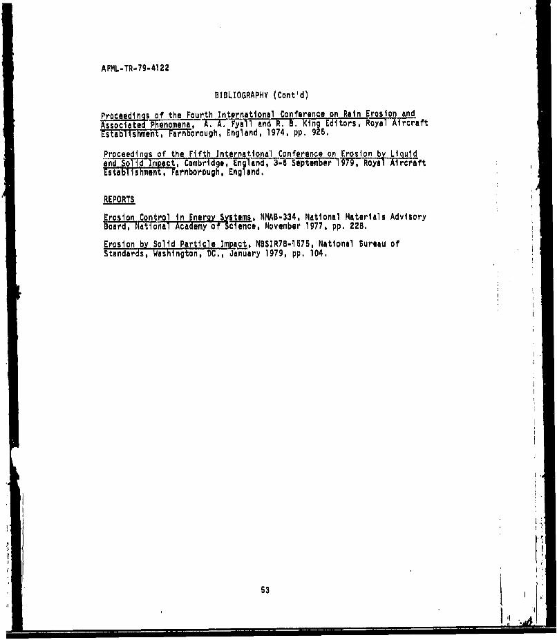
AFML-TR-79-4122
BIBLIOGRAPHY (Cont'd)
Proceedings of the Fourth International Conference on Rain Erosion andAssociated Phenomena, A. A. Fyall and R. B. King Editors, Royal Ar-aftEstablishment, Farnborough, England, 1974, pp. I25.
Proceedings of the Fifth International Conference on Erosion b- Liquidand Solid Impact, CambrtdgeEngland, 3--September I979 Royal AirciftEstablishment, Farnborough, England.
REPORTS
Erosion Contr.l inergy Systems., NMAB-334, National Materials AdvisoryBoard, National Academy of Science, November 1977, pp. 228.
Erosion by Solid Particle Impcjt, NBSIR78-l575, National Bureau ofStandards, Washington, DC,, January 1979, pp. 104.
53
- i m
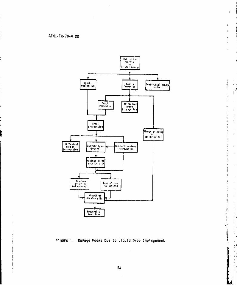
AFML-TR-79-41 22
C ro r.
~~igurec 1 . AmageModsDet iudD Impinementud Itkide54 tý hl t tU
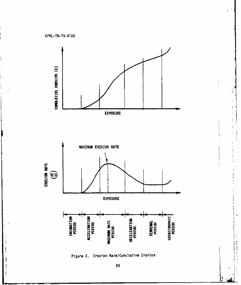
AFML-TR-79-4122
U.'
EXPOSURE
MAXIMUM EROSION RATE
N÷
EXPOSURE
IL.,
Figure 2. Erosion Rate/Cumulative Erosion
552
__________ I ,
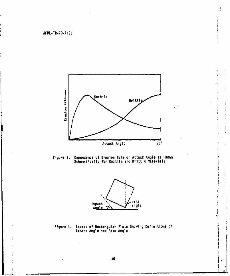
AFML-TR-79-41 22
Attack Anglo 900
Figure 3. Dependence of Erosion Rate on Attack Angle Is ShownSchematically for Ductile and Brittlo, Materials
a I@
Figure 4. Impact of Rectangular Plate Showing Definitions of
Impact Angle and Rake Angle
56
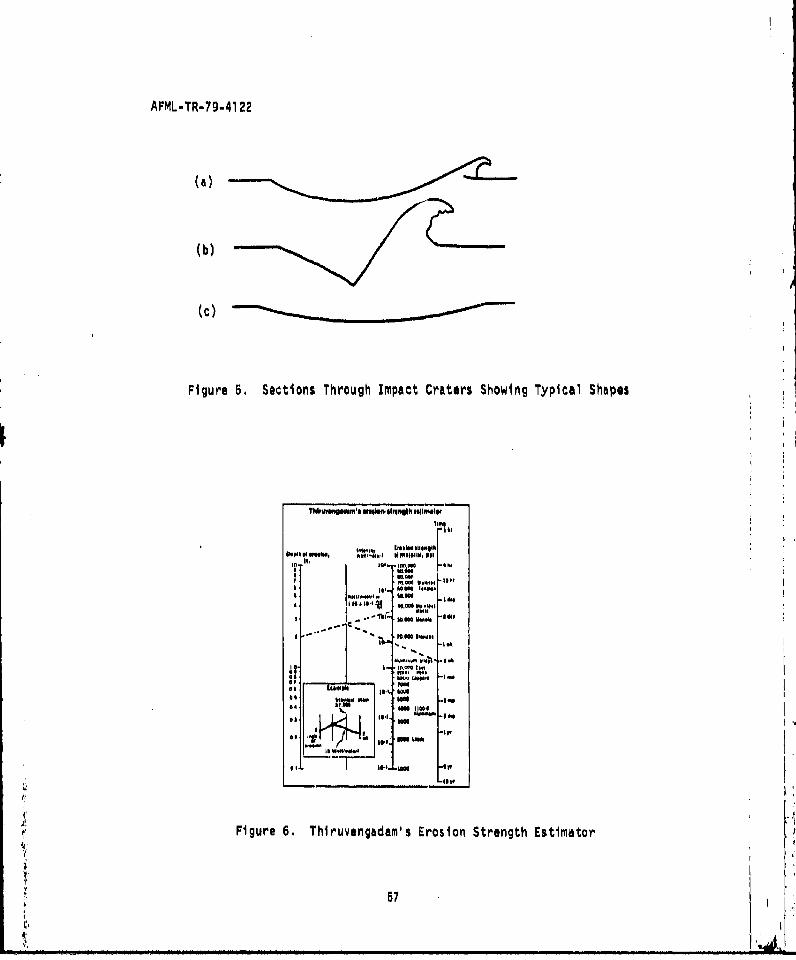
AFML-TR-79-41 22
(a)
(b)
(c)
Figure 5. Sections Through Impact Craters Showing Typical Shapes
POPIOOMN. MP111,41111. oi~elh
1. -1 MOM 0.
60~ SM~ e 14.0w
I el e e.
ING
raw 1440 W el t
M.t I M- -ey
Figure 6. Thlruvengadam's Erosion Strength Estimator
57
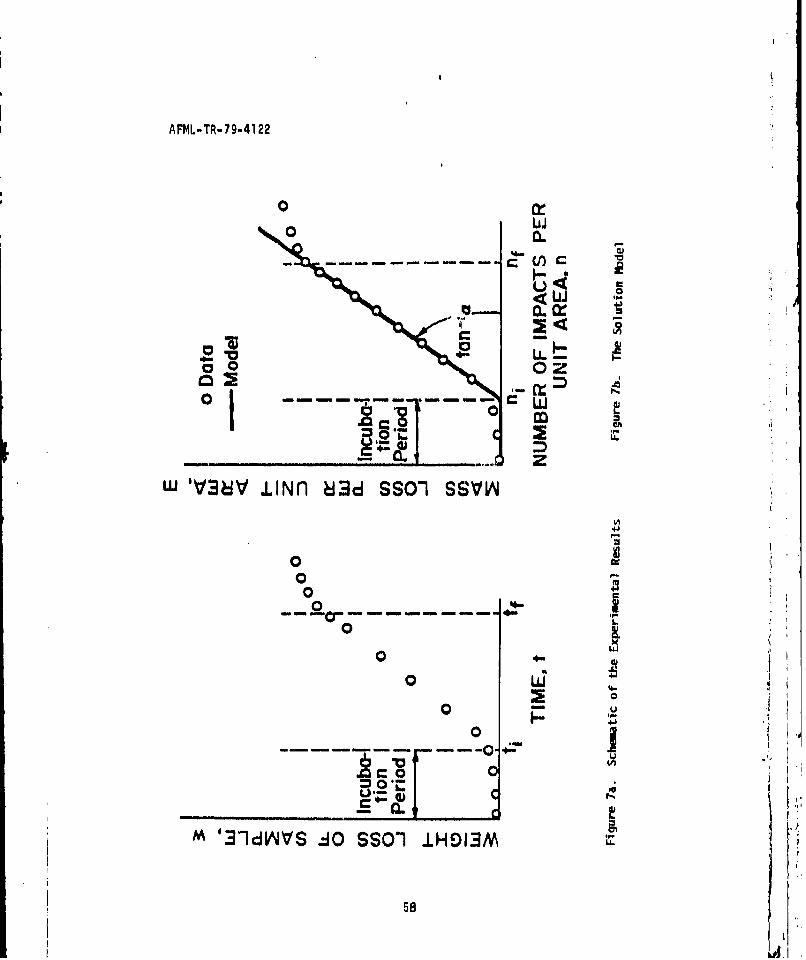
AFML-TR-79-41 22
00
-4-
0 -- -- LL0
-- zW ýi .LINnl ý3d SSO-1 SS~VV4
0
0 L
000
0 Kd
4-A
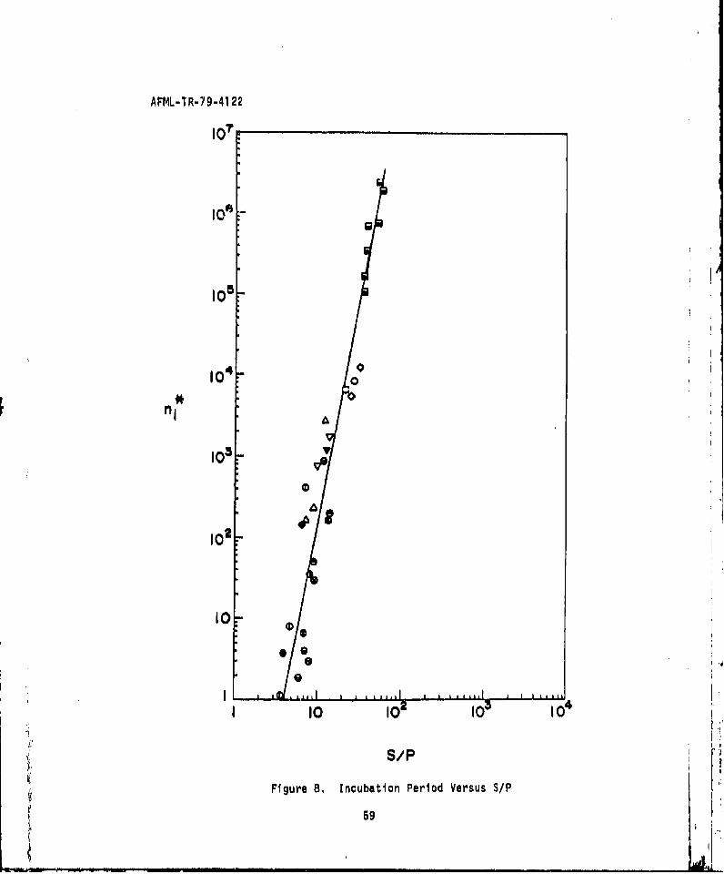
AFML-TR-79-41 22
107
I0-
108 54U
100F "*
nI
10 3-
0
-I 10 10 10 104
S/P
Figure 8, Incubation Period Versus S/P
59
ILAI
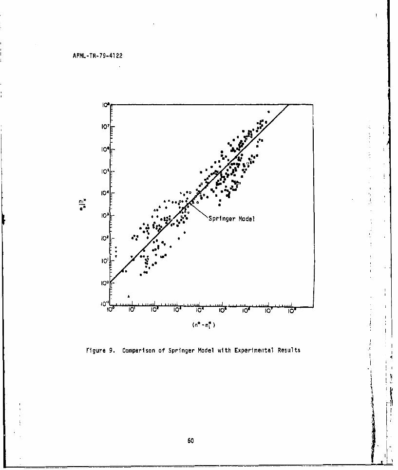
AFML-TR-79-4122
%' Ut
10, log A
lMS
0 0 v
' ',1t:'•,,•" Springer Model
,, ..,.,,, ,"u,rU
I0110. 5
i00
109' I0, 109 I08 104 1011 I0W -o lowI0
6~ 5 I
Figure 9. Comparison of Springer Model with Experimental Results
60
* ! 5
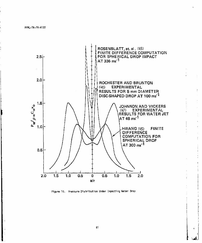
AFML-TR-79-4122
ROSENBLATT, et. al. (45)FINITE DIFFERENCE COMPUTATION
2.5 1 FOR SPHERICAL DROP IMPACTAT 336 ms" 1
I I I:~ I
2.0-I II ROCHESTER AND BRUNTON
(46) EXPERIMENTALI RESULTS FOR 5 mm DIAMETERDISC.SHAPED DROP AT 100 ms"1
1.5> JOHNSON AND VICKERS
(47) EXPERIMENTALRESULTS FOR WATER JET
Q HAT 46 ms"1
~-1.0-HWANG (45) FINITEDIFFERENCECOMPUTATION FORSPHERICAL DROPAT 300 ms"1
0.5 J
2.0 1.5 1.0 0.5 0 0.5 1.0 1'.5 2.0a/r
Figure 10. Pressure Distribution Under Impacting Water Drop
61
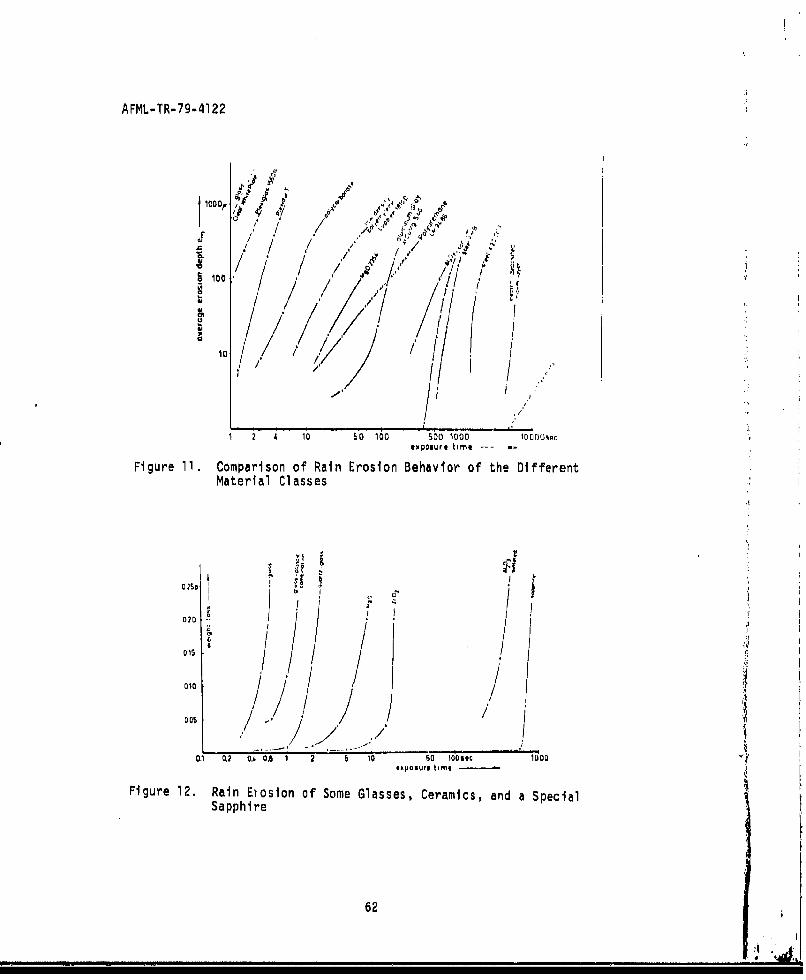
AFML-TR-79-4122
1000 ./ ..
,, /! / " /. U o , / / •# ,, / ,
. o • / i,.!
Al.
/ /x/osure tim ,../
III- t , I'
IoI.ur. tlm.l --- m
Figure 11. Comparison of Rain Erosion Behavior of the DifferentMaterial Classes
D I
o10.10 ,1/ I0°5 / -/
,' / / ,
0.1 0.2 0.4 0.6 1 2 6 10 60 i0os.c 1000Ixiosure time
Figure 12. Rain Etosion of Some Glasses, Ceramics, and a SpecialSapphire
62
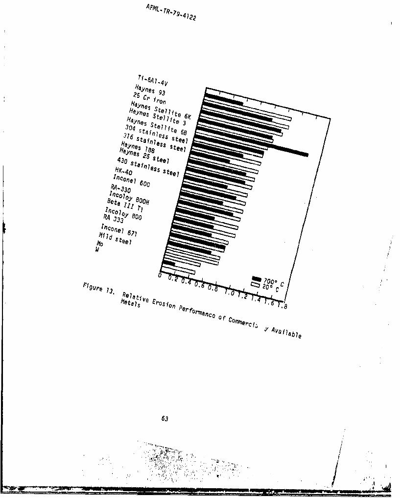
C'Y ne 93RYl5 sr
Haynes St0~t3C4 eltte 68"dynes~
J16 stain, V. 5 teel
Lio stee l
'flcone 1 600
RA-3 301flcolo 80Bete 1 2 r~z7~/
PA33y800
Mild ste
or'm~~~~n700 C1 ~l~~~
Met r' .j 6als roio PrfomacL.
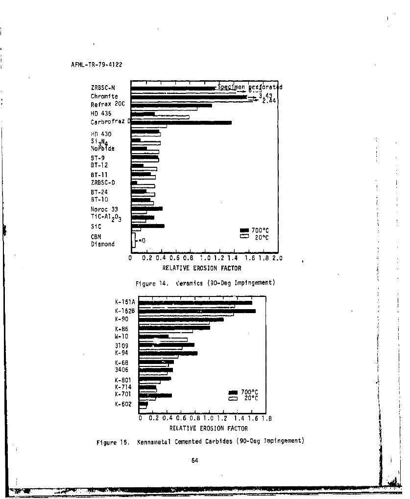
AFML-TR-79-4122
ZRBSC-M i I I en =g1frati d
Chromite 3,43.Refrax 20C I1_II _III _ __I
HD 435Carbrofraz
HD 430
Nor'btde
BT-9 •
BT-12BT-11ZRBSC-D
BT-24BT-10Noroc 33TiC-A1203
SiCm 700 0C
CBN no = 200CDiamond 0
0 0.2 0.4 0.6 0.8 1.0 1.2 1.4 1.6 1.8 2.0RELATIVE EROSION FACTOR
Figure 14. Ceramics (90-Deg Impingement)
K-151A I
K-162B ,,,,, -II__ _ _ _ _ _ _
K-90 m I
K-86W-10
3109K-94 -
K-683406K-801K-714K-701 700 0 C
200CK-602
I . I I I • 1 I I
0 0.2 0.4 0.6 0.8 1.0 1.2 1.4 1.6 1.8RELATIVE EROSION FACTOR
Figure 15, Kennametal Cemented Carbides (90-Deg Impingement)
64
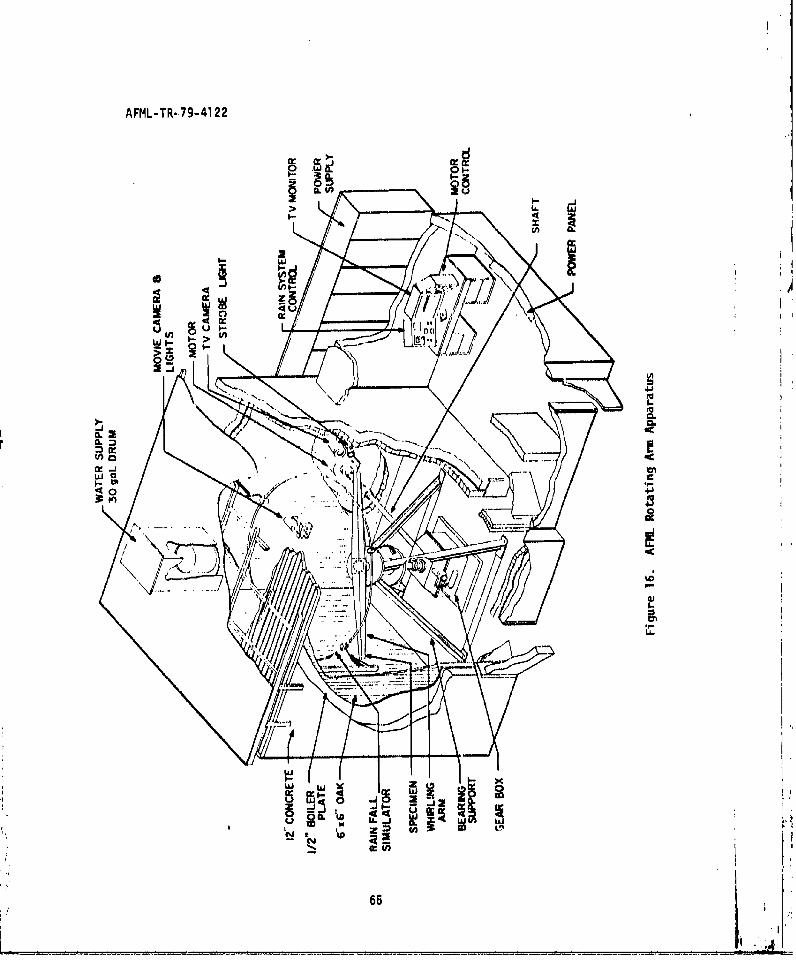
AFML-TR. 79-4122
WI-W
CLu
4 u.
CCOI m
p. 'K
CL z0I0
u65
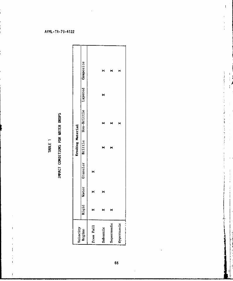
AFML-TR-79-4122
aJ
"P-4
co
00
o N
ap
CAd
w
44 t
o66
w
U ,
. ' ,H.S' 0 N IN
0 w
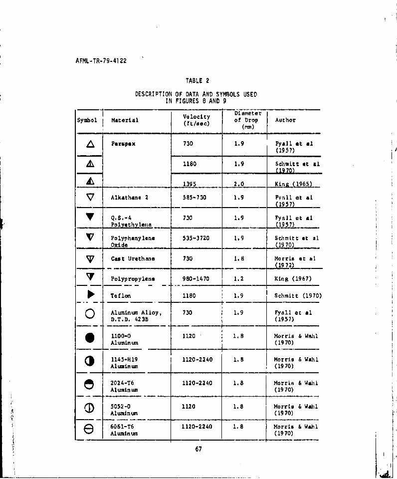
AFML-TR-79-41 22
TABLE 2
DESCRIPTION OF DATA AND SYMBOLS USEDIN FIGURES 8 AND 9
Velocity DiameterSymbol Material (ft/sec) of Drop Author
(mm)
/ Perspex 730 1.9 pyall et al(1957)
1180 1.9 Schmitt at Al, ~~( 19 70) ...
-r __1395 2.0 Kinp&(L96,5)
V Alkathane 2 585-730 1.9 pynll at al(1957)
V Q.S,-4 730 1.9 Fynll et al_ Polyethyle (1957)
[7 Polyphenylene 535-3720 1.9 Sdimitt et alOxide (19 70)
Cast Urethane 730 1.8 Morris at hl_ _-- (19 72)
Polypropylene 980-1470 1.2 Kin8 (1967)
Teflon 1180 1.9 Schmitt (1970)
O Aluminum Alloy, 730 1.9 Fyall et alD.T.D. 423B (1957)
O 1100-0 1120 1.8 Morris & WahlAlumin um (1970)
(J 1145-H19 1120-2240 1.8 Morris & WahlAluminum (19 70)
e 2024-T6 1120-2240 1.8 Morris & WahlAlumin um (1970)
(I 5052-0 1120 1.8 Morris & WahlAluminum (1970)
e 6061-T6 1120-2240 1.8 Morris & WahlAluminum (1970)
67
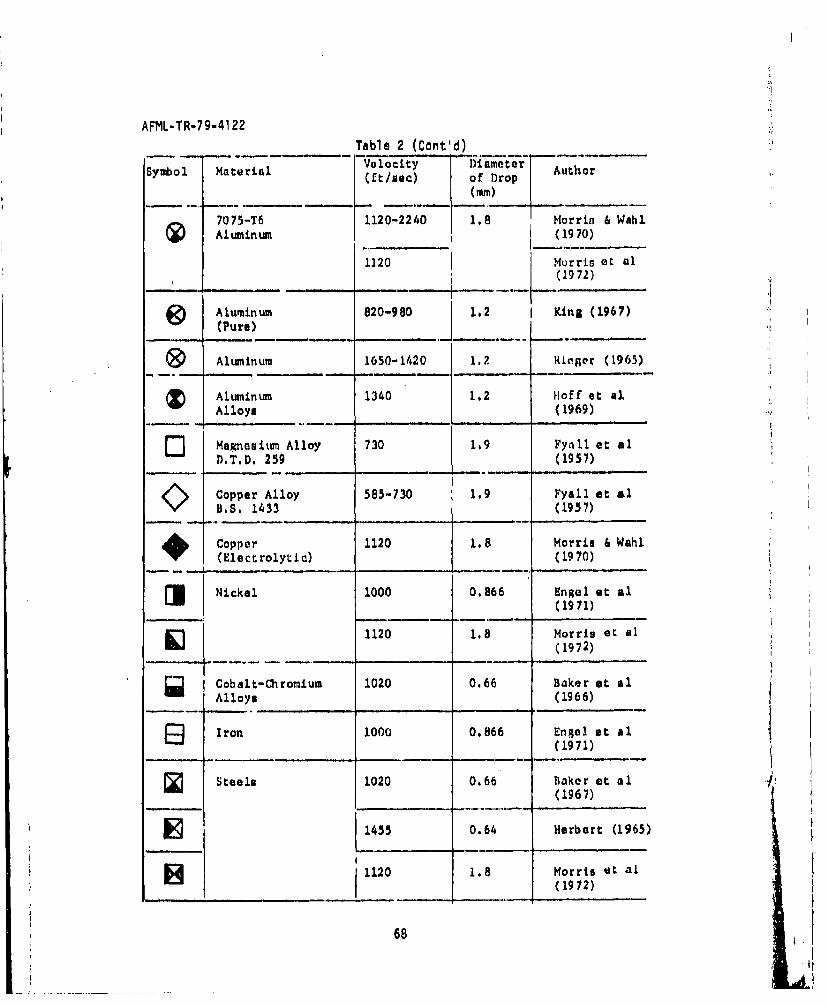
AFML-TR-79-4122Table 2 (Cont'd)
Symbol Material Velocity Diameter Author(ft/sec) of Drop
(Mm)
7075-T6 1120-2240 1.8 Morrin s WahlAluminum (1970)
1120 Morris et al(1972)
•) Aluminum 820-980 1.2 I King (1967)(Pure) ,
SAluminum 1650-1420 1.2 Risgor (1965)
SAluminum 1340 1.2 H~off et alAlloys (1969)
E Magnesitm Alloy 730 1.9 Fyall et alD.T.D. 259 (1957)
SCopper Alloy 585-730 1.9 Fyall at alB.S. 1433 (1957)
, Copper 1120 1.8 Morris & Wahl(Electrolytic) (19 70)
Nickel 1000 0.866 Engel at al(1971)
1120 1.8 Morris et al(1972)
Cobalt-Chromium 1020 0.66 Baker at alAlloys (1966)
9 Iron 1000 0.866 Engel at al(1971)
Steels 1020 0.66 Baker at al(1967)
S1455 0.64 Herbert (1965)
1120 1.8 Morris dt al
(1972)
68
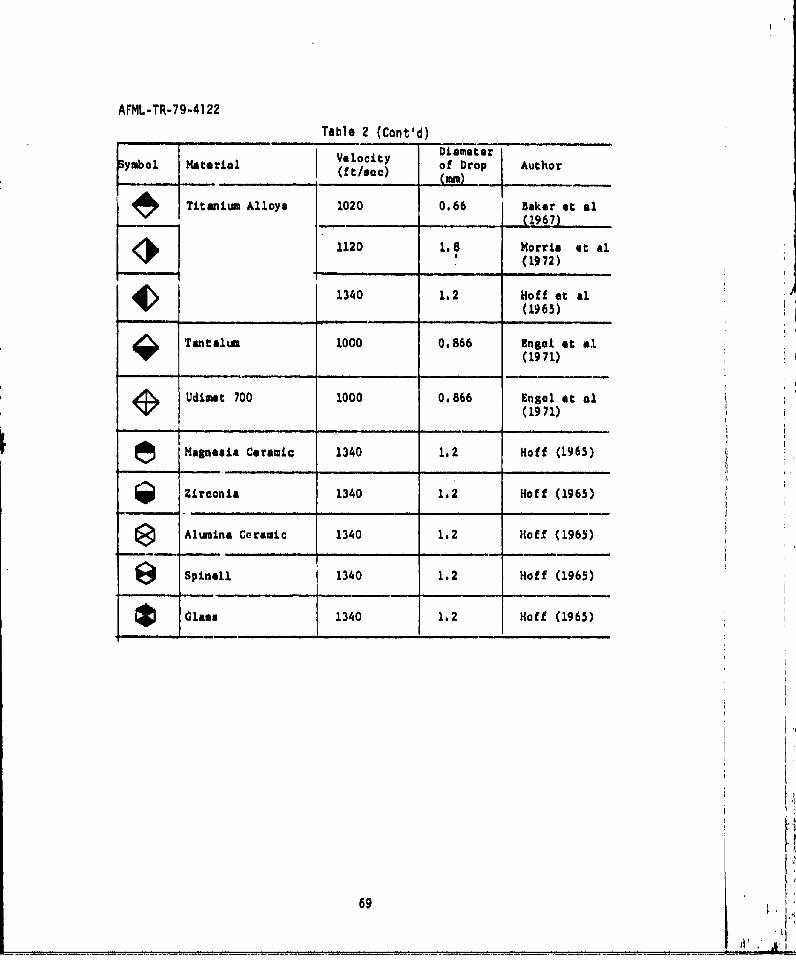
AFML-TR-79-4122Table 2 (Cont'd)
Velocity DiameterSymbol mterial (ft/Vec) of Drop Author
(___/___)_ _ (196)
itanium Alloys 1020 0.66 Baker et al(1967)1120 1.8 Morris at al.
12 (1972)
4 1340 1.2 Hoff at aL(1965)
Tantalum 1000 0.866 Engel et &1(1971)
2 Udimet 700 1000 0.866 Engol at al(1971)
Magnesia Ceramic 1340 1.2 Hoff (1965)
SZirconia 1340 1.2 Hoff (1965)
SAlumina Ceramic 1340 1.2 H1off (1965)
e Spinell 1340 1.2 Hoff (1965)
Glasu 1340 1.2 Hoff (1965)
69
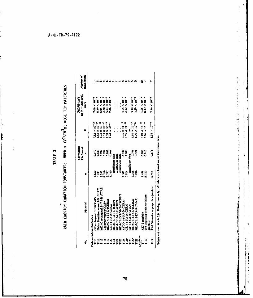
AFML-TR-79-4122
cease a- .
; -! x x x x x x x x x
l l l l ti
"x -".
I.A
I- I
70
IA ~ @~ dO
SIm m mm m 1 [ •m l l I ' i4 l l
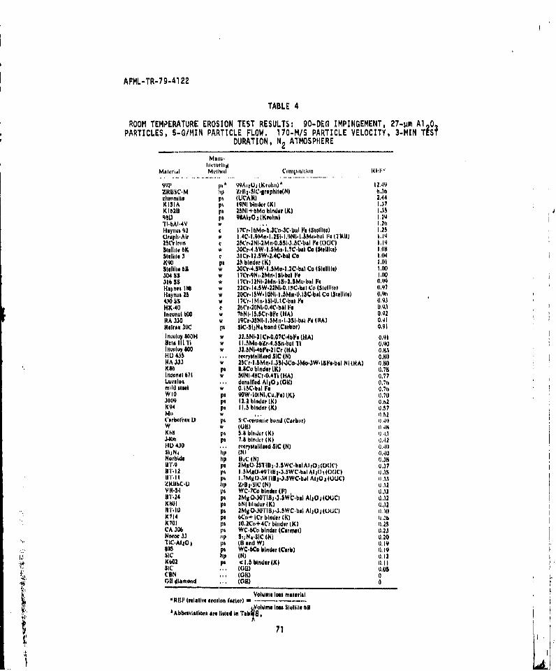
AFML-TR-79-41 22
TABLE 4
ROOM TEMPERATURE EROSION TEST RESULTS: 90-DEG IMPINGEMENT, 27-)4m Al 0PARTICLES, 5-G/MIN PARTICLE FLOW. 17O-M/S PARTICLE VELOCITY, 3-MIN TIP~
DURATION, N2 ATMOSPHERE
1z9KDS C - uli ZrB,.SSIC~mraphile(N) UhMclavnnuhle PI (UCAI4I 2.44KISIApa qNb K(.)KID pa P' NI+6Mo bimdor(K) I.11%5
98D p, 98AI,0, (Krohu) 1.2111'I-bAI*4V IN . .2tiHsynoh 93 9 Ir.bib3i.Culpe (Stillile) 1.25CriapI-Air F ,CI9nI2II'N~.MuI 4 0111 K) 1.1J
SuII1he 6K w 3OCr*4.3W-.5I.~o-I.7C-bAl Cc (31,111t.) Hill1$141i1143 .ll10.12,3W'21AC-Ibul Co 1,04K90 ps 26 binder WK Lill1S1eII1te bB w 30cr.-4,5W- Lsmo-l,2C-ba Cc (SIeIIHIQe I.M3Do4 SS w lCr.9N1.2Mn-l~i-bAl Poe HK)311155 w I7Cr-I2Ni-2Mh-ISi-2.SMu~bNI Fk 0.441Hoynes 1861 w 22Cr-I4,SW'22NI-0,ISC-bmI Cti(Se0111l 0.117
li2t II w 20Cr.I&W-lONi. I .51vin-0L.130Cbal Cc (Slitihliv 0,4114. 5w M7r.i1NI". I Si.o.I C-bal li 0.4.3
HK-40 C Wlir-20N1.O,4C-bal lie01lIttnedl bo00 w UINII5,SCr-S~lr (HA) 0.92KA 330 w I9C05JNI-Il,~n'l.JSI-bal Fe WiA) 0.41Hencex 20C III SIC-Slii~ bond MCariam) 0.91Ilelouil 800H w 32,SNI-2I Cr-007C4b~iu (HA) 0.41Bel& I I TI I LIsmo-bzr-.4,S1n-bal TI 0.4)0Ie"Coley 600 w 313,NI-40I~e-21Cr (HA) ((.N11HI) 435 .. ret ryste~li~ed SIC (N) OX1))HA 333 w MSr. L,&MI.l,31.311CO.3Nlo,3 lS~ie- bi N I IRA) ().go0KS11 pa 8.11Cu binder WK 0(.7111Intcomie 1171 w 50Nl-411Cr.O,4T1 (HA) (0.77Luvmloc ... deamifled A11Oj (OU) (1.7 himild steel w 0. 15C-bal Fe 0.74aW10 pa 90w-I~lNi.CwO) (K) 11.703109 ps 12. 1 binder (K.) ((h2K94 pa I L5 binder (K) (157mo w , 1(.52Carbo'iree ID ps SIC-cueramic( buind (Carbor) 0.44
Khh1 Im 5.1 bliidur WK 0(.4.1341011, p 7.11 biner~ WK 0,.12HI) 430 ... mryiytallmaed SIC (N)) 0(.40$01 4 hp (N) 0(.40)Norbide hp II4C (IN ((38HT.9 ps 2mxO-131Ill p..SWC-bsIAl tO.i (CVWI ((.3BT- 12 ps 1. .MMO-4911 111.3.-SWC. be I At20 14i00 1(.15U I'd I pk I-700MMU.311Ilili.-3,3WC-bial A1j(Ou UCK) 1(.,13lZROS~C.I.U lip ZrO .I-si (N) 0.32VR11.4 In WC-1Co binedr (F) u0.1281T241 pa M1 O.3I0-'iID,-.,SkbbaI A110jlOUCl 0.12K1101 pa tiNI lihditlr WK 1.13)
W 10ps 2M11O30'IIBpJ.5WC-bsI A110j(UUC) 11.11)K 714 111 bCo+ I Cr binder (K) 01.26,K701 pa I10 -We+ 4Crblitn dorIK) 0Z.3CA 30b pi WC-bCo binder (Curmaui 0.23Norrie 33 lip S(1N4*S(C (N) 0,20TIC.AI1 Oj III (B And W) 0.19-i895 pa WC.6Co binder (Curb) 0.191
Ilk si p IN) 0.12K602 pa1 4 1.5 binder (K) (1.11SIC' ... (OR) 0,05CON ,. (OR)0
14On iliamond . (C)0
Volume (los eMate,(a(
:,etvainsatlisted In Ta (ecbiigt 6
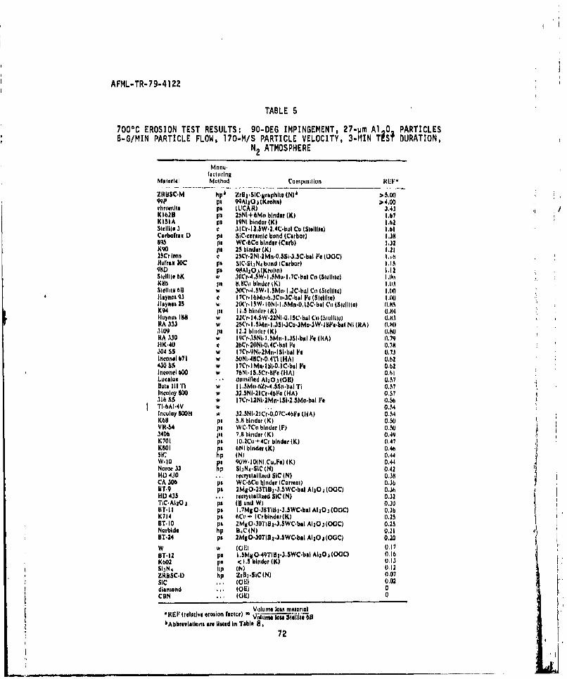
AFML-TR-79-41 22
TABLE 5
7008C EROSION TEST RESULTS: 90-DEG IMPINGEMENT, 27-urn Al 0 PARTICLES5-G/MIN PARTICLE FLOW, 170-M/S PARTICLE VELOCITY, 3-MIN TiSR DURATION,
N2 ATMOSPHERE
Material Method CompositionRE
ZI4ISC'M hiss zrliuCj eps~oN ~ ~ ~ )"IsP pa 90Ai0j jIrohn) > 4.00Ouhwmlle pa ILCARt) 3.43 'K1620 ps 2ZsNi+bMo binder (K) 1.67KISIA ps OqN binder (K) 1.62Stelil~l 3 C 3ICr.12.5W2.,41C-bi, Co lSmIville) 1.611Carboftim D) pa SiC-cetamici bond (Carbor) Las5
85Pm WC.bCo bindar (Caub) 1.32K90 pa 23 binder (K) 1.2125Cr Iron C 25Cr.2Ni,2Mn-0.SSi.Jl.SC-b&l Pa (i)GC) I.f i Iml4~raa 20c pm SIC-SihN4 bund (Carbor) 1.1698Di pa 9tiA11O. hlJiuln) 1.12SigIIitt bK w" 3~.,WI 1M~7~a Co (Swulilemo I .tttKuh Its 8.8Co biogidr (K) 1.11.18t16liw 06" w 3OCr'.i,5W I .SMe I .2C-baI Co (SwIllitul I 0t"Iaytic. 93 t I ?Cr- 6l)b-oCo.3C-b&I Fit (Stallilte) 1.001lInyimam 21 %, 20(r.ISW-iONi-.5iS -0, 13C~bAl 0i (Stiolitoi ().NX94 I 1.5 bhitder (K) .(Iloynua 188 w 22CHO4,W-22N1-.150b~lul Cit (hiuliito) I.tM)RA .133 w 25Cr. 1.5MwI. SI ,SJCoJ1Mo.3 W. lSPm-bal N I (R(A) (Ci.R11109 PI 12.2 bitnder (K) ().NO0RA 330 w lKr3 i.,Mni5.b Pe 1(RA) 0.79HK.40 9 2e6r.20NI.0.4C0bal Pit 0.79304 £5 w 17Cr.9INi.21k~t.ISI-bal Fa 0. 73lnconeI 671 w 50N`1-48Cr.0A1I (HA) 0.h243055 w Mlr.IWnISI.0,IC-bal Pa 011)2Incomol 600 IN 76NI-I.l5,0.S111 (HA) 0.61Lucalue . dunmilid AlS10.1 (01) 0.51nowa iirri w I I .SMontfZr-4.SSn.bAI TI 0.47Incohny SOC w 32.5NI'2ir.45I~a (HA) (1.57316 S5 w 17Cr-I2NI-1Mr%-ISi-3,5Mo-bal Pa (1.5oTI6A164V w ,... 0.34Incitlay S0Oh w 32-SNi.21Cr-0.07C-4bjF* (HA) 0.54K68 p. 5.8 hinder (K) 0.50VR-54 ps WC.7Cu binder (F) 0.503406 pm1 7.8 binder (K) 0t.49,K701 pa I0-2Cu+ 4Cr binder (K) 0,47K801 ps 6141 binder tK) 0.46SIC hip (N) 0.,44W-1O pa QOW.10(Ni,CuPe) (K) 0.44Noroo 33 hp SbjN4-SiC (N) 0.42HI) 4J0 ... reserystailimad SIC (N) 0.311CA 306 pa WC.6C7u Iiinder (Carnmai) 0.3bBTr.9 pa 2MS0.2s'riB1.3.swc.bal AI~j0 0C)C 0.36Hi) 435 ,.., rogryslalliald SIC (N) 0.32TIC.Alia~ pa In and W) 0.30111T.11 pa I -71V .3III0311T 3,JISWC-bal AIj~j (QO1C) 0. 11K714 pa 6Co+ ICrbinder(K) 01.25ell-i0 pa 2MXO.30Ti8z.3.SWC-bal Alizj(OGC) 0.25 iNorbide lip 04C (N) 0.21DT-24 pa 2MgO.3OTiD 1.J.SWC-bai Aia j (OGCI 0.20W w ((1W 1)011sT. 12 pa I .5IM~gO49Ti1a*3,SWC-bal Al~j j(0C) 0.16K601 Ina < 1 . binder (K) (113SiJNa lip (N) (1.12ZRBSC-D hip ZrB2'SIC (N) 0.07sic.. (013) 0.02diamond . (GE) 0CBN WE)(13 0
VUlume 1oan MaterialRtEP (relative erosion NaOWr '~I0 i~ a.5eiI 1
bAbb~myialoris are lised in Table 872
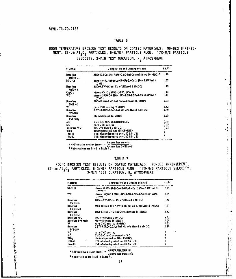
AFML-TR-79-4122
TABLE 6
ROOM TEMPERATURE EROSION TEST RESULTS ON COATED MATERIALS: 90-DEG IMPINGE-MENT, 27-rim Al 20 3 PARTICLES, 5-G/MIN PARTICLE FLOW. 170.MIS PARIICLE
VELOCITY, 3-MIN TEST DURATION, N2 ATMOSPHERE
Material Compostilon and Coating Method
80ororue MSr.lO.SCo-ZP..7.SW.OSC-bal Co w/dlrfumed H (MD0~ 1,40Slallite 31
Ni-Cr.U plwmna 0,SC.4SiIb~.t6 4B.4F,.2,4Cu.2,4Mo2.24W.bAI NI 1.32(CWS)
sororuac 29Cr.4,W.IC-batl Co w/diffusod 8 (MDC) 2Sleilite a1
CrICI pluaa Cr 10 3.55IOj.3TIO I (CWS) 1.23WC plasma 3.4(WC+ 8111)1 ICr.2I.502S5F.23S~i-0.5C-baI NI 1.1I
(CW5)Bororulut J1Cr-I2.SW.2.4C'bal Co w/ditruaed 8 (MDC) 0.92
SW41lite 3IN pure CVI) coatling (KMKtC) 0.53Bofofuae 0.5TI-0,0Br.0.03C~bal Mo w/dIffusild B (MDC) 0.10
MT-104Bororluaw Mo w/dlffused B (MDC) 0.25
PM molysic CVI) SIC on C converted to SIC (11.06sic pure CVL1 calting 0.115Ilortfulf WC WC w/dIffuted 0 (MUCI 0.02Til03 electrtidepoalled over NI (CPMRC) 0190-311 'till 2liclcrodeposIted over J310 SS (UT) 019A-13 TIR 2 eleclt odopoalled over 3105SS (U 1) 0
'RPF (relative 4rosinn ractor) - Vol t -Inte loss malerialVIlu me loss Shallte 69~Abbreviations are listed In Table 8.
TABLE 7
7000C EROSION TEST RESULTS ON COATED MATERIALS: 90-DEG IMPINGEMENT,27-tim Al 20 3 PARTICLES, 5-G/MIN PARTICLE FLOW. 170-M/S PARTICLE VELOCITY,
3-MIN TEST DURATION, N 2 ATMOSPHERE
malarial Compotllott Atnd Coaling Method R lp,
?4i.Cr.Bl plaisva 0.SC"4SI-i6Cr.48.4Pe.2.4Cu.2.4Mo2.,4W~bal NI 2.79fCWSIA
WC pln~ma 351 WC+SNjI. I ICr.2.SB2.2SFe-2.5SI-0.SC~bAINI 2.06(CWS?
Hooruifue 29Cr-4.5W I C-bal Co w/dlffused B (MDCI 1.40Stll,. 6
Doorrius, 2SCr*I0.5Co*2Fr*7.SW'0.5C-baI Co w/dilfluaed B (MDC) 1.37Stil~le 31
Bororuse 3lCH'2.5W.2.41C.bal Co w/dllfuaed B (MDC) 0.113skulll 3
Borofus. WC WC wi/dilrused 0 IMDC) 0.72Borofust PM moly Mo w/dllfused B IML)CI 0.2m1W pure CVI) coatinii iIMRC) 05.2.5ilorfuse 0.STI'0,QB-r.0O3Cr.bal Mo wycliffused 11 (MDC) 0.19
sic pure CVD coaling 0sic CVI) SIC on C contvortad cij SIC 0niu v~uiridepsson%ituu cia NI ((P'M 140 1
AcI18111.11 'rI j eleI rhodelpccield on .10 o i Uan 919A.13 11BO I lect rode pu% ied oil 310 SS (UTI 0
REF (relative erosion factor) Vlu.It tallVoclume loas Slelilit 68
bAbbrsvlatlona are hlsed In Tobie 3.
73
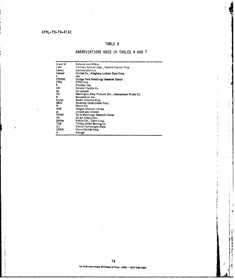
AFML-TR-79-4122
TABLE 8
ABBREVIATIONS USED IN TABLES 4 AND 7
IH and W lBLabcock nmd WikloxC'arti (arlmloy System, Dqlp., Geimer.'I Elec.tri Carp,Carbur Ca rliorundu C'o,Carmel Carmel Co.. Allegheny Ludlum Steul Corp,
CPMRC College Park Metallurgy HReurch CenterCWS CWS Corp,F a slall.hI [, Inc.UiJ Hetmerul Fllectl'l Co.hp hct prLisudHA HunilnAgIon Alloy I'rducLs Dlv.. International Nickel Co,K Kemianeiatl, It.,Kruhn Krohnm Ceraimics Corp.MDC Malerlalk I)uvoloprntimt Corp.N Nurltmmi Co.OCC Orevltli (Il'adumlll LCentar
rnasked and %interedVMClolla Metallurgy lHI~oserch Canlter,RA Iile1d Alloys Corp.
Sleillte Stallil LAYv,, Cabot Corp.TI8 Tilmikeo oi lir lHtrrii1 Cu.UT Litiled 'I'velihol•1g•e Corp.UCAH Union Carbide Corp.w wrougltl
(
I
''
74 ..ci90,.0/4"wU,.3Grvernment Printing offl its 1980l -- 657.044/424 ; '