after college varify today
DESCRIPTION
after collegeTRANSCRIPT
Advanced Electrical Energy Prepaid Metering System
CHAPTER-1
INTRODUCTION
1.1 Introduction of AEEPM:
The technology for the electrical measuring instrument has become improved from what it was from last few years. From the large size of meters with highly magnets and coils, there have been many innovations that have resulted in size & weight reduction in addition to improvise the specifications and features. In the last few year there are an improvements have been seen in the accuracy & determination. Introduction of the digital meter in the later part of last century hasfully altered the way Electrical parameters are measured. Starting with Voltmeters & Ammeters, the digital meter has conquered the whole spectrum of analysing instruments due to their advantages like ease of reading, better determination and rugged construction. Of particular significance is the introduction of the Electronic Energy Meter in the mid eighties. Now a days, Expenditure and distribution of energy has become a big object for discussion because of huge difference in energy production and consumption. In this regard, the frequent power cut is the big reason for the energy consumer; another important reason for power failure is due to the un-limited use of energy by rich people. In this aspect, there should be some restriction to distribute the power in all areas to minimize the power cuts and according to that the Government should implement a policy, by introducing advanced Electrical Energy Prepaid Metering(AEEPM) System everywhere in domestic division. Hence, the need has come to think on this line and a solution has to be come out.
1.2 Electrical Metering Instrument Technology
Today the measuring instrument technology improved up significantly, so that the Consumed energy can be calculated mathematically, displayed, data can be Processed, data can be stored, etc. Presently the microcontrollers are playing major role in metering instrument technology.
Page 1

Advanced Electrical Energy Prepaid Metering System
1.3 About Electronic Energy Meter
The following are the advantages of electronic energy meter:
1.3.1 Accuracy
While electromechanical measuring instruments are generally available with accuracy of Class2, Electronic measuring instruments of Class 1 accuracy are very common.
1.3.2 Low Current Performance
After a few years most of the electromechanical meters tend to slower performance and stop recording at. This problem arises due to increase in friction at their bearings. This results in large losses in revenue since most of the residential consumers will be running at very low loads for almost 20 hours in a day. Electronic meters record consistently and accurately even Also they are guaranteed to start recording energy at0.4% of their basic current.
1.3.3 Low Voltage Performance
Below75% of rated voltage the accuracy of mechanical meter becomes poor whereas accuracy electronic meters record good even at 50% of rated voltage. This become a major advantage where low voltage problem is very common.
1.3.4 Installation
The position in which the mechanical meter is installed is very sensitive. If it is not mounted vertically, it will not perform well and resulting in revenue loss whereas electronic meter is not sensitive to position.
1.3.5 Tamper
The mechanical meters can be tampered easily by use of magnet externally or by inserting an thin film into the meter to touch the rotating disc without disturbing the Wiring. In addition to these methods, in the case of a single-phase meter, there are more than 20 conditions of external wiring that can make the meter record less. In the case of 3 Phase meter, external wiring can be manipulated in 4
Page 2
Advanced Electrical Energy Prepaid Metering System
ways to make it slow. Hence, any of these methods cannot tamper electronic meters. Further they can detect the tampering of meter by using LED.
1.4 New Features in AEEPM System
Electronic meters provide many new features like prepaid metering that can improve the efficiency of the utility. Shows the Block Diagram of Advanced Electrical Energy Prepaid Metering System in Fig. 1 . The Central controlling unit in AEEPM System is PIC16F877A Microcontroller . It controls all the activity related to the presented System . It is responsible for alert the consumer while recharging and exhausting the recharge amount.
1. Block Diagram of AEEPM System
Fig. 1 Block Diagram of AEEPM System
Page 3

Advanced Electrical Energy Prepaid Metering System
2. Schematic Diagram
Fig 2. Schematic Diagram of AEEPM System
3. PCB Layout
Fig. 3. PCB Layout Of AEEPM System
Page 4

Advanced Electrical Energy Prepaid Metering System
Steps Followed , while preparing Printing Circuit Board .
The Main Point of Printed Circuit is that , routing of electric current and signals through a thin copper layer ,among Electronic components. PCB is also provide mechanical support to all component . There are following important steps followed during PCB Designing .
1. Design of Circuit – Design of circuit prepare with manually and software both . There are many PCB Designing software available in Market such as Eagle , protel and Tina Pro etc.
2. Printing of Circuit on PCB – Taking print out of circuit and print this on PCB using Suitable means of printing.
3. Etching Process – In Etching process , whole PCB dip into the required chemical such as Ferric Chloride or Ammonium per-sulphate and remove all unprinted surface of PCB.
4. Route Checking and Drilling - In this Process firstly ,we have to check route or track , then after drilling is done.
5. Component Assembling and Soldering – After Drilling Process component assembling on PCB through holes and Soldering them.
1.4.1 Prepaid Energy Metering
In the last decade there are many advancements are done in energy meter which is only direct revenue interface between serviceability and consumers. The conventional electro-mechanical meters are being replaced with electronic meters to improve accuracy in meter reading. Asian countries are currently making plans to present prepaid electricity meters across their whole network in which they distribute energy, beyond up by the success of this novel methodology in South Africa. In Asia the major driving factor for energy market are the privatization of
Page 5

Advanced Electrical Energy Prepaid Metering System
state held power distribution companies and the main existing problems with the post-paid system.
Over 40 countries have implemented prepaid meters in their markets In United Kingdom the system, has been in use for well over 70 years with about3.5 million consumers. The prepaid program in South Africa was started in 1992 since then they have installed over 6 million meters. Other African counties such as Sudan, Madagascar are following the South African success. The concept has found ground in Argentina and New Zealand with few thousands of installations. The prepaid meters in the market today
1.4.2 PREPAYMENT METERING
Yet another advantage of the electronic meter is the possibility of introducing Prepaid metering system. In prepaid metering system the consumer pays money in advance for the service and then feed this information into his/her meter. The meter then updates the credit available to the consumer and starts deducting his consumption from available credit. Once the credit reaches a minimum specified value, meter for users. If the credit is completely exhausted, the meter switches off the loads of the consumer.
Main advantage of this system is that the utility can eliminate meter readers. Another benefit is that they get paid in advance. The consumer benefits due to elimination of penalty for late payment. Also it enables him to plan his electricity bill expenses in a better manner. Due to the intelligence built in into the electronic meters, introduction of prepaid metering becomes much easier than in the case of electromechanical meters.
1.4.3 Security concept in AEEPM – The present system , is more secure than currently used electrical energy meter because it has no. of security element such as vibration sensing element , pulse measuring element , overload detector and fault detector. Vibration sensing element is able to alert the electricity office if vibration related action found. As same as fault detector and overload detector element is alert the user if suitable event occurs for this.
Page 6

Advanced Electrical Energy Prepaid Metering System
CHAPTER-2
2 . LITERATURE REVIEW OF “AEEPM” SYSTEM
Mr. Nazir Bin Abdullah [1], developed an automatic meter reading system (Automation of Residential Electricity Cut off Using Embedded Controller) In 2012 for domastic user.In this project he used GSM modem for transmitting and receiving information, both sides means user side and energy provider side. The heart of this project is a embedded device (microcontroller unit) which control the main power switch and update the data in data base .with help of this project user shows their energy consumption and billing information. Mr. Hung Cheng Chen[2] proposed a wireless automatic meter reading system in 2012. In this project he used zigbee modul on both sides. This technology is chip and low cost. Mr. Alauddin Al –Omary[3] develop an automatic meter reading system using GPRS technology In 2011 .This paper the design of secure low cost AMR system that calculate and transmit the total electrical energy consumption to main server using GSM technology .The AMR system perform the main three function such as taking meter reading ,transmission facility and billing information. MR.LI Quan Xi[4] design a automatic meter system based on ZigBee and GPRS system In 2010 . Mr. H.G..Rodney Tan[5] Develop an automatic power meter reading system using GSM network.in 2007.In this system GSM digital power meter installed in every consumer unite and electricity ebilling system at the energy provider side. Mr. Mejbaui Haque[6] develop a microcontroller based single phase digital prepaid energy meter for improved meter and billing system .In this paper he present a single phase energy meter IC.This digital prepaid meter does not have any rotating part .The energy is calculated using the output pulse of energy meter and the counter of microcontroller. Amit jain [7],proposed a prepaid meter using mobile communication in2011.In this system he used controller unite,prepaid card and communication module .The prepaid card is the most important addition to the design .The power utility sets the amount in the prepaid card to a measure that the consumer recharges the cards ,called fixed amount.The tariff rates are already programmed and fed into the card. Fawzi Al-Naina and Bahaa Jalil[8],Built a prototyping prepaid electricity meter system based on RFID .This system is divided into two part such as client and server .The client consist of a digital meter based on a microcontroller and an RFID reader and the server consist of a PC with
Page 7

Advanced Electrical Energy Prepaid Metering System
MySQL database server.The client installed in each house and the server installed in local sub station.
Page 8

Advanced Electrical Energy Prepaid Metering System
CHAPTER-3
3. DESIGN PRINCIPAL OF THE SYSTEM - In the design of AEEPM System is Completed with Hardware and Software Tool Both.
3.1 DESCRIPTION OF COMPONENT
The Present system prepared with combination of hardware and software .
3.1.1 Hardware Description
3.1.1(a) MICROCONTROLLER UNITE
PIC 16 SERIES-PIC16F73
Fig. 4. Pin Diagram of Microcontroller Unit
Page 9

Advanced Electrical Energy Prepaid Metering System
PIC microcontrollers made by Microchip Technology and derived from the PIC1640 which actuallly developed by General Instrument's Microelectronics . The name PIC referred to "Peripheral Interface Controller".
It is available in different configurations such as 8bit,16 bit,32 bit package with instructions set as given below :
8 bit pakage -PIC10 xxxx, PIC12 xxxx, PIC16 xxxx, PIC18 xxxx.(12 bit instruction set)
16 bit pakage -PIC24H,DSPIC30,DSPIC33. (14 bit instruction set)
32 bit pakage -PIC32xxxx. (16 bit instruction set)
PICs are famous with developers and hobbyists like due to their low cost, large availability, large user base, large collection of application notes, availability of low cost or free development tools, and serial programming facility.
Special Microcontroller Features:• High performance CPU.• Only thirty five single word instructions to learn.• All single cycle instructions except for program branches which are two-cycle.• Operating speed: DC - 20 MHz clock input DC - 200 ns instruction cycle.• Up to 8K x 14 words of FLASH Program Memory, Up to 368 x 8 bytes of Data Memory (RAM).• Interrupt Facility .• 5 level deep hardware stack.• Direct Addressing, Indirect Addressing and Relative Addressing modes.• Power-on Reset Facility.• Power-up Timer Facility and Oscillator Start-up Timer Facility.• Watchdog Timer Facility with its own on-chip RC oscillator for reliable operation.• Programmable code protection Facility.• Facility of Power saving SLEEP mode.• In-Circuit Serial Programming Facility.
Peripheral Features:
Page 10

Advanced Electrical Energy Prepaid Metering System
There are three types of timer provided by PIC Family such as Timer0, Timer1 and Timer2.
• Timer0 is a 8-bit timer/counter with 8-bit prescaler.• Timer1 is a 16-bit timer/counter with prescaler, can be incremented during SLEEP via external crystal/clock.• Timer2 is a 8-bit timer/counter with 8-bit period register, prescaler and postscaler.• 2 Capture, Compare and PWM modules-- Capture is 16-bit, max. resolution is 12.5 ns- Compare is 16-bit, max. resolution is 200 ns- PWM max. resolution is 10-bit.• 8-bit and 8-channel A/Digital converter.• Synchronous Serial Port (SSP) with SPI (Master mode) and I2C(Slave).• Universal Synchronous Asynchronous Receiver Transmitter (USART/SCI).• Parallel Slave Port (PSP), 8-bits wide with external RD, WR and CS controls (40/44-pin only).• Brown-out detection circuitry for Brown-out Reset (BOR).
CMOS Technology:• It consume Low power as compare to others .• It has Fully static design .• It has Wide operating voltage range i.e. 2.0V to 5.5V.• High Sink/Source Current.•Wide Industrial temperature range.• Low power consumption.PIN Diagram
Page 11

Advanced Electrical Energy Prepaid Metering System
Page 12

Advanced Electrical Energy Prepaid Metering System
Page 13

Advanced Electrical Energy Prepaid Metering System
Table. 1. Pin Description of Microcontroller Unit
ELECTRICAL CHARACTERISTICS
Absolute Maximum Ratings †Ambient temperature under bias...................................... .-55 to +125°C
Storage temperature.................................................... -65°C to +150°C
Page 14

Advanced Electrical Energy Prepaid Metering System
Voltage on any pin with respect to VSS (except VDD, MCLR. and RA4) ......................................... -0.3V to (VDD + 0.3V)
Voltage on VDD with respect to VSS............................. -0.3 to +6.5V
Voltage on MCLR with respect to VSS (Note2)..........................0 to +13.5V
Voltage on RA4 with respect to Vss ..................................0 to +12V
Total power dissipation (Note 1)................................................1.0W
Maximum current out of VSS pin................................................300 mA
Maximum current into VDD pin .....................................................250 mA
Input clamp current, IIK (VI < 0 or VI > VDD)............................ ± 20 mA
Output clamp current, IOK (VO < 0 or VO > VDD) ...................... ± 20 mA
Maximum output current sunk by any I/O pin..................................25 mA
Maximum output current sourced by any I/O pin ............................25 mA
Maximum current sunk by PORTA, PORTB, and PORTE (combined) (Note 3).....................................200 mA
Maximum current sourced by PORTA, PORTB, and PORTE (combined) (Note 3) ..............................................200 mAMaximum current sunk by PORTC and PORTD (combined) (Note 3) ..................................................................200 mAMaximum current sourced by PORTC and PORTD (combined) (Note 3).............................................................200 mA
Note 1: Power dissipation is calculated as follows: Pdis = VDD x {IDD - Σ IOH}
Page 15

Advanced Electrical Energy Prepaid Metering System
+ Σ {(VDD - VOH) x IOH} + Σ(VOl x IOL)
2: Voltage spikes below VSS at the MCLR pin, inducing currents greater than 80 mA, may cause latch-up. Thus,
a series resistor of 50-100Ω should be used when applying a “low” level to the MCLR pin, rather than pullingthis pin directly to VSS.
3.1.1.(b) DISPLAY UNITE
Introduction:
Fig. 5. Display Unit
A liquid crystal display (LCD) is a thin, flat display device made up of any number of color or monochrome pixels arrayed in front of a light source or reflector. Each pixel consists of a column of liquid crystal molecules suspended between two transparent electrodes, and two polarizing filters, the axes of polarity of which are perpendicular to each other. Without the liquid crystals between them, light passing through one would be blocked by the other. The liquid crystal twists the polarization of light entering one filter to allow it to pass through the other.
Page 16

Advanced Electrical Energy Prepaid Metering System
A program must interact with the outside world using input and output devices that communicate directly with a human being. One of the most common devices attached to an controller is an LCD display. Some of the most common LCDs connected to the controllers are 16X1, 16x2 and 20x2 displays. This means 16 characters per line by 1 line 16 characters per line by 2 lines and 20 characters per line by 2 lines, respectively.
Many microcontroller devices use 'smart LCD' displays to output visual information. LCD displays designed around LCD NT-C1611 module, are inexpensive, easy to use, and it is even possible to produce a readout using the 5X7 dots plus cursor of the display. They have a standard ASCII set of characters and mathematical symbols. For an 8-bit data bus, the display requires a +5V supply plus 10 I/O lines (RS RW D7 D6 D5 D4 D3 D2 D1 D0). For a 4-bit data bus it only requires the supply lines plus 6 extra lines(RS RW D7 D6 D5 D4). When the LCD display is not enabled, data lines are tri-state and they do not interfere with the operation of the microcontroller.
Features:
(1) Interface with either 4-bit or 8-bit microprocessor.
(2) Display data RAM
(3) 80x8 bits (80 characters).
(4) Character generator ROM
(5). 160 different 57 dot-matrix character patterns.
(6). Character generator RAM
(7) 8 different user programmed 5 7 dot-matrix patterns.
(8).Display data RAM and character generator RAM may be
Accessed by the microprocessor.
(9) Numerous instructions
(10) .Clear Display, Cursor Home, Display ON/OFF, Cursor ON/OFF,
Page 17
available. Line lengths of 8, 16, 20, 24, 32 and 40 characters are all standard, in one, two

Advanced Electrical Energy Prepaid Metering System
Blink Character, Cursor Shift, Display Shift.
(11). Built-in reset circuit is triggered at power ON.
(12). Built-in oscillator.
Data can be placed at any location on the LCD. For 16×1 LCD, the address locations are:
Table 2. Address locations for a 1x16 line LCD
Shapes and sizes:
Fig. 6. Various Shapes of Display Unit
Page 18

Advanced Electrical Energy Prepaid Metering System
Even limited to character based modules, there is still a wide variety of shapes and sizes available. Line lengths of 8,16,20,24,32 and 40 characters are all standard, in one, two and four line versions.
Several different LC technologies exists. “supertwist” types, for example, offer Improved contrast and viewing angle over the older “twisted nematic” types. Some modules are available with back lighting, so so that they can be viewed in dimly-lit conditions. The back lighting may be either “electro-luminescent”, requiring a high voltage inverter circuit, or simple LED illumination.
ELECTRICAL BLOCK DIAGRAM:
Page 19

Advanced Electrical Energy Prepaid Metering System
Fig. 7. Block Diagram of Display Unit
Power supply for lcd driving:
PIN DESCRIPTION:
Most LCDs with 1 controller has 14 Pins and LCDs with 2 controller has 16 Pins (two pins are extra in both for back-light LED connections).
Page 20

Advanced Electrical Energy Prepaid Metering System
Fig 8. Pin Diagram of 1x16 lines lcd
Table. 3. Pin Details of Display Unit
CONTROL LINES:
EN:
Line is called "Enable." This control line is used to tell the LCD that you are sending it data. To send data to the LCD, your program should make sure this line is low (0)
Page 21

Advanced Electrical Energy Prepaid Metering System
and then set the other two control lines and/or put data on the data bus. When the other lines are completely ready, bring EN high (1) and wait for the minimum amount of time required by the LCD datasheet (this varies from LCD to LCD), and end by bringing it low (0) again.
RS:
Line is the "Register Select" line. When RS is low (0), the data is to be treated as a command or special instruction (such as clear screen, position cursor, etc.). When RS is high (1), the data being sent is text data which sould be displayed on the screen. For example, to display the letter "T" on the screen you would set RS high.
RW:
Line is the "Read/Write" control line. When RW is low (0), the information on the data bus is being written to the LCD. When RW is high (1), the program is effectively querying (or reading) the LCD. Only one instruction ("Get LCD status") is a read command. All others are write commands, so RW will almost always be low.
Finally, the data bus consists of 4 or 8 lines (depending on the mode of operation selected by the user). In the case of an 8-bit data bus, the lines are referred to as DB0, DB1, DB2, DB3, DB4, DB5, DB6, and DB7.
Logic status on control lines:
• E - 0 Access to LCD disabled
- 1 Access to LCD enabled
• R/W - 0 Writing data to LCD
- 1 Reading data from LCD
• RS - 0 Instructions
- 1 Character
Page 22

Advanced Electrical Energy Prepaid Metering System
Writing data to the LCD:
1) Set R/W bit to low
2) Set RS bit to logic 0 or 1 (instruction or character)
3) Set data to data lines (if it is writing)
4) Set E line to high
5) Set E line to low
Read data from data lines (if it is reading)on LCD:
1) Set R/W bit to high
2) Set RS bit to logic 0 or 1 (instruction or character)
3) Set data to data lines (if it is writing)
4) Set E line to high
5) Set E line to low
Entering Text:
First, a little tip: it is manually a lot easier to enter characters and commands in hexadecimal rather than binary (although, of course, you will need to translate commands from binary couple of sub-miniature hexadecimal rotary switches is a simple matter, although a little bit into hex so that you know which bits you are setting). Replacing the d.i.l. switch pack with a of re-wiring is necessary.
The switches must be the type where On = 0, so that when they are turned to the zero position, all four outputs are shorted to the common pin, and in position “F”, all four outputs are open circuit.
All the available characters that are built into the module are shown in Table 3. Studying the table, you will see that codes associated with the characters are quoted in binary and hexadecimal, most significant bits (“left-hand” four bits) across the top, and least significant bits (“right-hand” four bits) down the left.
Most of the characters conform to the ASCII standard, although the Japanese
Page 23

Advanced Electrical Energy Prepaid Metering System
and Greek characters (and a few other things) are obvious exceptions. Since these intelligent modules were designed in the “Land of the Rising Sun,” it seems only fair that their Katakana phonetic symbols should also be incorporated. The more extensive Kanji character set, which the Japanese share with the Chinese, consisting of several thousand different characters, is not included!
Using the switches, of whatever type, and referring to Table 3, enter a few characters onto the display, both letters and numbers. The RS switch (S10) must be “up” (logic 1) when sending the characters, and switch E (S9) must be pressed for each of them. Thus the operational order is: set RS high, enter character, trigger E, leave RS high, enter another character, trigger E, and so on.
The first 16 codes in Table 3, 00000000 to 00001111, ($00 to $0F) refer to the CGRAM. This is the Character Generator RAM (random access memory), which can be used to hold user-defined graphics characters. This is where these modules really start to show their potential, offering such capabilities as bar graphs, flashing symbols, even animated characters. Before the user-defined characters are set up, these codes will just bring up strange looking symbols.
Page 24

Advanced Electrical Energy Prepaid Metering System
Page 25

Advanced Electrical Energy Prepaid Metering System
Initialization by Instructions:
Fig. 8. Process Diagram of Display Unit
Page 26

Advanced Electrical Energy Prepaid Metering System
3.1.1(c) ENERGY METER
Electromechanical meters
The most common type of electricity meter is the Thomson or electromechanical induction watt-hour meter, invented by Elihu Thomson in1888.
Technology
The electromechanical induction meter operates by counting the revolutions of an aluminum disc which is made to rotate at a speed proportional to the power. The number of revolutions is thus proportional to the energy usage. It consumes a small amount of power, typically around 2 watts. The metallic disc is acted upon by two coils. One coil is connected in such a way that it produces a magnetic flux in proportion to the voltage and the other produces a magnetic flux in proportion to the current. The field of the voltage coil is delayed by 90 degrees using a lag coil. [1]This produces eddy currents in the disc and the effect is such that a force is exerted on the disc in proportion to the product of the instantaneous current and voltage. A permanent magnet exerts an opposing force proportional to the speed of rotation of the disc - this acts as a brake which causes the disc to stop spinning when power stops being drawn rather than allowing it to spin faster and faster. This causes the disc to rotate at a speed proportional to the power being used. The type of meter described above is used on a single-phase AC supply. Different phase configurations use additional voltage and current coils.
Reading
The aluminum disc is supported by a spindle which has a worm gear which drives the register. The register is a series of dials which record the amount of energy used. The dials may be of the cyclometer type, an odometer-like display that is easy to read where for each dial a single digit is shown through a window in the face of the meter, or of the pointer type where a pointer indicates each digit. It should be noted that with the dial pointer type, adjacent pointers generally rotate in opposite directions due to the gearing mechanism. The amount of energy represented by one revolution of the disc is denoted by the symbol ‘Kh’ which is given in units of watt-hours per revolution.
Page 27

Advanced Electrical Energy Prepaid Metering System
Fig. 9. Single phase energy meter
The value 7.2 is commonly seen. Using the value of Kh, one can determine their power consumption at any given time by timing the disc with a stopwatch. If the time in seconds taken by the disc to complete one revolution ist , then the power in watts is. For example, if Kh = 7.2, as above, and one revolution took place in 14.4 seconds, the power is 1800 watts. This method can be used to determine the power value 7.2 is commonly seen. Using the value of Kh, one can determine their power consumption at any given time by timing the disc with a stopwatch. If the time in seconds taken by the disc to complete one revolution is’t , then the power in watts is. For example, if Kh= 7.2, as above, and one revolution took place in 14.4 seconds, the power is 1800 watts. This method can be used to determine the power consumption of household devices by switching them on one by one.
Most domestic electricity meters must be read manually, whether by are presentative of the power company or by the customer. Where the customer reads the meter, the reading may be supplied to the power company by telephone, post or over the internet. The electricity company will normally require a visit by a company representative at least annually in order to verify customer-supplied readings and to make a basic safety check of the meter.
Accuracy
Page 28

Advanced Electrical Energy Prepaid Metering System
In an induction type meter, creep is a phenomenon that can adversely affect accuracy, that occurs when the meter disc rotates continuously with potential applied and the load terminals open circuited. A test for error due to creep is called a creep test.
3.1.1(d) COMMUNICATION MODULE
Introduction:
GSM (Global System for Mobile communications) is a cellular network, which means that mobile phones connect to it by searching for cells in the immediate vicinity. GSM networks operate in four different frequency ranges. Most GSM networks operate in the 900 MHz or 1800 MHz bands. Some countries in the Americas use the 850 MHz and 1900 MHz bands because the 900 and 1800 MHz frequency bands were already allocated.
The rarer 400 and 450 MHz frequency bands are assigned in some countries, where these frequencies were previously used for first-generation systems.
GSM-900 uses 890–915 MHz to send information from the mobile station to the base station (uplink) and 935–960 MHz for the other direction (downlink), providing 124 RF channels (channel numbers 1 to 124) spaced at 200 kHz. Duplex spacing of 45 MHz is used. In some countries the GSM-900 band has been extended to cover a larger frequency range. This 'extended GSM', E-GSM, uses 880–915 MHz (uplink) and 925–960 MHz (downlink), adding 50 channels (channel numbers 975 to 1023 and 0) to the original GSM-900 band. Time division multiplexing is used to allow eight full-rate or sixteen half-rate speech channels per radio frequency channel. There are eight radio timeslots (giving eight burst periods) grouped into what is called a TDMA frame. Half rate channels use alternate frames in the same timeslot. The channel data rate is 270.833 kbit/s, and the frame duration is 4.615 ms.
GSM Advantages:
GSM also pioneered a low-cost, to the network carrier, alternative to voice calls, the Short t message service (SMS, also called "text messaging"), which is now supported on other mobile standards as well. Another advantage is that the standard includes one worldwide Emergency telephone number, 112. This makes it easier for
Page 29

Advanced Electrical Energy Prepaid Metering System
international travelers to connect to emergency services without knowing the local emergency number.
The GSM Network:
GSM provides recommendations, not requirements. The GSM specifications define the functions and interface requirements in detail but do not address the hardware. The GSM network is divided into three major systems: the switching system (SS), the base station system (BSS), and the operation and support system (OSS).
Fig. 10 The Switching System
Page 30

Advanced Electrical Energy Prepaid Metering System
The Switching System:
The switching system (SS) is responsible for performing call processing and subscriber-related functions. The switching system includes the following functional units.
Home location register (HLR): The HLR is a database used for storage and management of subscriptions. The HLR is considered the most important database, as it stores permanent data about subscribers, including a subscriber's service profile, location information, and activity status. When an individual buys a subscription from one of the PCS operators, he or she is registered in the HLR of that operator.
Mobile services switching center (MSC): The MSC performs the telephony switching functions of the system. It controls calls to and from other telephone and data systems. It also performs such functions as toll ticketing, network interfacing, common channel signaling, and others.
Visitor location register (VLR): The VLR is a database that contains temporary information about subscribers that is needed by the MSC in order to service visiting subscribers. The VLR is always integrated with the MSC. When a mobile station roams into a new MSC area, the VLR connected to that MSC will request data about the mobile station from the HLR. Later, if the mobile station makes a call, the VLR will have the information needed for call setup without having to interrogate the HLR each time.
Authentication center (AUC): A unit called the AUC provides authentication and encryption parameters that verify the user's identity and ensure the confidentiality of each call. The AUC protects network operators from different types of fraud found in today's cellular world.
Equipment identity register (EIR): The EIR is a database that contains information about the identity of mobile equipment that prevents calls from stolen, unauthorized, or defective mobile stations. The AUC and EIR are implemented as stand-alone nodes or as a combined AUC/EIR node.
The Base Station System (BSS):
Page 31

Advanced Electrical Energy Prepaid Metering System
All radio-related functions are performed in the BSS, which consists of base station controllers (BSCs) and the base transceiver stations (BTSs).
BSC: The BSC provides all the control functions and physical links between the MSC and BTS. It is a high-capacity switch that provides functions such as handover, cell configuration data, and control of radio frequency (RF) power levels in base transceiver stations. A number of BSCs are served by an MSC.
BTS: The BTS handles the radio interface to the mobile station. The BTS is the radio equipment (transceivers and antennas) needed to service each cell in the network. A group of BTSs are controlled by a BSC.
The Operation and Support System
The operations and maintenance center (OMC) is connected to all equipment in the switching system and to the BSC. The implementation of OMC is called the operation and support system (OSS). The OSS is the functional entity from which the network operator monitors and controls the system. The purpose of OSS is to offer the customer cost-effective support for centralized, regional and local operational and maintenance activities that are required for a GSM network. An important function of OSS is to provide a network overview and support the maintenance activities of different operation and maintenance organizations. GSM Network Areas:
The GSM network is made up of geographic areas. As shown in bellow figure, these areas include cells, location areas (LAs), MSC/VLR service areas, and public land mobile network (PLMN) areas.
Fig. 11 Area of GSM Network
Page 32

Advanced Electrical Energy Prepaid Metering System
Location Areas:
The cell is the area given radio coverage by one base transceiver station. The GSM network identifies each cell via the cell global identity (CGI) number assigned to each cell. The location area is a group of cells. It is the area in which the subscriber is paged. Each LA is served by one or more base station controllers, yet only by a single MSC Each LA is assigned a location area identity (LAI) number.
MSC/VLR service areas:
An MSC/VLR service area represents the part of the GSM network that is covered by one MSC and which is reachable, as it is registered in the VLR of the MSC.
PLMN service areas:
The PLMN service area is an area served by one network operator.
GSM Specifications:
Specifications for different personal communication services (PCS) systems vary among the different PCS networks. Listed below is a description of the specifications and characteristics for GSM.
Frequency band: The frequency range specified for GSM is 1,850 to 1,990 MHz (mobile station to base station).
Duplex distance: The duplex distance is 80 MHz. Duplex distance is the distance between the uplink and downlink frequencies. A channel has two frequencies, 80 MHz apart.
Channel separation: The separation between adjacent carrier frequencies. In GSM, this is 200 kHz.
Modulation: Modulation is the process of sending a signal by changing the characteristics of a carrier frequency. This is done in GSM via Gaussian minimum shift keying (GMSK).
Page 33

Advanced Electrical Energy Prepaid Metering System
Transmission rate: GSM is a digital system with an over-the-air bit rate of 270 kbps.
Access method: GSM utilizes the time division multiple access (TDMA) concept. TDMA is a technique in which several different calls may share the same carrier. Each call is assigned a particular time slot.
Speech coder: GSM uses linear predictive coding (LPC). The purpose of LPC is to reduce the bit rate. The LPC provides parameters for a filter that mimics the vocal tract. The signal passes through this filter, leaving behind a residual signal. Speech is encoded at 13 kbps. .
Main AT commands:
"AT command set for GSM Mobile Equipment” describes the Main AT commands to communicate via a serial interface with the GSM subsystem of the phone.
AT commands are instructions used to control a modem. AT is the abbreviation of Attention. Every command line starts with "AT" or "at". That's why modem commands are called AT commands. Many of the commands that are used to control wired dial-up modems, such as ATD (Dial), ATA (Answer), ATH (Hook control) and ATO (Return to online data state), are also supported by GSM/GPRS modems and mobile phones. Besides this common AT command set, GSM/GPRS modems and mobile phones support an AT command set that is specific to the GSM technology, which includes SMS-related commands like AT+CMGS (Send SMS message), AT+CMSS (Send SMS message from storage), AT+CMGL (List SMS messages) and AT+CMGR (Read SMS messages).
Note that the starting "AT" is the prefix that informs the modem about the start of a command line. It is not part of the AT command name. For example, D is the actual AT command name in ATD and +CMGS is the actual AT command name in AT+CMGS. However, some books and web sites use them interchangeably as the name of an AT command.
Here are some of the tasks that can be done using AT commands with a GSM/GPRS modem or mobile phone:
Page 34

Advanced Electrical Energy Prepaid Metering System
Get basic information about the mobile phone or GSM/GPRS modem. For example, name of manufacturer (AT+CGMI), model number (AT+CGMM), IMEI number (International Mobile Equipment Identity) (AT+CGSN) and software version (AT+CGMR).
Get basic information about the subscriber. For example, MSISDN (AT+CNUM) and IMSI number (International Mobile Subscriber Identity) (AT+CIMI).
Get the current status of the mobile phone or GSM/GPRS modem. For example, mobile phone activity status (AT+CPAS), mobile network registration status (AT+CREG), radio signal strength (AT+CSQ), battery charge level and battery charging status (AT+CBC).
Establish a data connection or voice connection to a remote modem (ATD, ATA, etc).
Send and receive fax (ATD, ATA, AT+F*).
Send (AT+CMGS, AT+CMSS), read (AT+CMGR, AT+CMGL), write (AT+CMGW) or delete (AT+CMGD) SMS messages and obtain notifications of newly received SMS messages (AT+CNMI).
Read (AT+CPBR), write (AT+CPBW) or search (AT+CPBF) phonebook entries.
Perform security-related tasks, such as opening or closing facility locks (AT+CLCK), checking whether a facility is locked (AT+CLCK) and changing passwords (AT+CPWD).(Facility lock examples: SIM lock [a password must be given to the SIM card every time the mobile phone is switched on] and PH-SIM lock [a certain SIM card is associated with the mobile phone. To use other SIM cards with the mobile phone, a password must be entered.])
Control the presentation of result codes / error messages of AT commands. For example, you can control whether to enable certain error messages (AT+CMEE) and whether error messages should be displayed in numeric format or verbose format (AT+CMEE=1 or AT+CMEE=2).
Page 35

Advanced Electrical Energy Prepaid Metering System
Get or change the configurations of the mobile phone or GSM/GPRS modem. For example, change the GSM network (AT+COPS), bearer service type (AT+CBST), radio link protocol parameters (AT+CRLP), SMS center address (AT+CSCA) and storage of SMS messages (AT+CPMS).
Save and restore configurations of the mobile phone or GSM/GPRS modem. For example, save (AT+CSAS) and restore (AT+CRES) settings related to SMS messaging such as the SMS center address.
3.1.1(e) Circuit Isolation Device
Introduction:
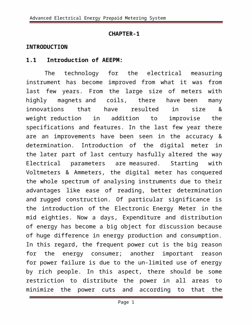
A relay is an electrical switch that opens and closes under the control of another electrical circuit. In the original form, the switch is operated by an electromagnet to open or close one or many sets of contacts. A relay is able to control an output circuit of higher power than the input circuit, it can be considered to be, in a broad sense, a form of an electrical amplifier.
Fig. 12 Circuit Isolation Device
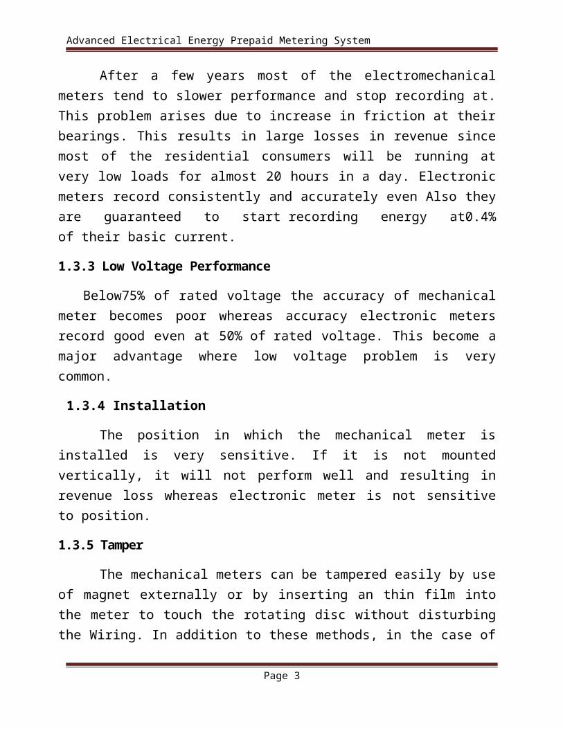
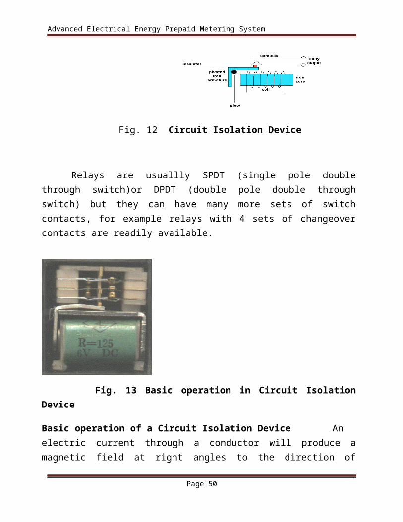
Relays are usuallly SPDT (single pole double through switch)or DPDT (double pole double through switch) but they can have many more sets of switch contacts, for example relays with 4 sets of changeover contacts are readily available.
Page 36

Advanced Electrical Energy Prepaid Metering System
Fig. 13 Basic operation in Circuit Isolation Device
Basic operation of a Circuit Isolation Device An electric current through a conductor will produce a magnetic field at right angles to the direction of electron flow. If that conductor is wrapped into a coil shape, the magnetic field produced will be oriented along the length of the coil. The greater the current, the greater the strength of the magnetic field, all other factors being equal.
Page 37

Advanced Electrical Energy Prepaid Metering System
Inductors react against changes in current because of the energy stored in this magnetic field. When we construct a transformer from two inductor coils around a common iron core, we use this field to transfer energy from one coil to the other. However, there are simpler and more direct uses for electromagnetic fields than the applications we've seen with inductors and transformers. The magnetic field produced by a coil of current-carrying wire can be used to exert a mechanical force on any magnetic object, just as we can use a permanent magnet to attract magnetic objects, except that this magnet (formed by the coil) can be turned on or off by switching the current on or off through the coil.
If we place a magnetic object near such a coil for the purpose of making that object move when we energize the coil with electric current, we have what is called a solenoid. The movable magnetic object is called an armature, and most armatures can be moved with either direct current (DC) or alternating current (AC) energizing the coil. The polarity of the magnetic field is irrelevant for the purpose of attracting an iron armature. Solenoids can be used to electrically open door latches, open or shut valves, move robotic limbs, and even actuate electric switch mechanisms and is used to actuate a set of switch contacts
Applications:
To control a high-voltage circuit with a low-voltage signal, as in some types of modems or audio amplifiers, To control a high-current circuit with a low-current signal, as in the starter solenoid of an automobile, To detect and isolate faults on transmission and distribution lines by opening and closing circuit breakers (protection relays), To isolate the controlling circuit from the controlled circuit when the two are at different potentials, for example when controlling a mains-powered device from a low-voltage switch. The latter is often applied to control office lighting as the low voltage wires are easily installed in partitions, which may be often moved as needs change. They may also be controlled by room occupancy detectors in an effort to conserve energy,
To perform logic functions. For example, the boolean AND function is realised by connecting NO relay contacts in series, the OR function by connecting NO contacts
Page 38

Advanced Electrical Energy Prepaid Metering System
in parallel. The change-over or Form C contacts perform the XOR (exclusive or) function. Similar functions for NAND and NOR are accomplished using NC contacts. The Ladder programming language is often used for designing relay logic networks. o Early computing. Before vacuum tubes and transistors, relays were used as logical elements in digital computers. See ARRA (computer), Harvard Mark II, Zuse Z2, and Zuse Z3.
3.5.1(f) Power Supply:
Power supply is a reference to a source of electrical power. A device or system that supplies electrical or other types of energy to an output load or group of loads is called a power supply unit or PSU. The term is most commonly applied to electrical energy supplies, less often to mechanical ones, and rarely to others
This power supply section is required to convert AC signal to DC signal and also to reduce the amplitude of the signal. The available voltage signal from the mains is 230V/50Hz which is an AC voltage, but the required is DC voltage(no frequency) with the amplitude of +5V and +12V for various applications.
In this section we have Transformer, Bridge rectifier, are connected serially and voltage regulators for +5V and +12V (7805 and 7812) via a capacitor (1000µF) in parallel are connected parallel as shown in the circuit diagram below. Each voltage regulator output is again is connected to the capacitors of values (100µF, 10µF, 1 µF, 0.1 µF) are connected parallel through which the corresponding output(+5V or +12V) are taken into consideration.
Page 39

Advanced Electrical Energy Prepaid Metering System
Fig. 14 Circuit Diagram of Power Supply
Circuit Explanation
(a)Transformer
A transformer is a device that transfers electrical energy from one circuit to another through inductively coupled electrical conductors. A changing current in the first circuit (the primary) creates a changing magnetic field; in turn, this magnetic field induces a changing voltage in the second circuit (the secondary). By adding a load to the secondary circuit, one can make current flow in the transformer, thus transferring energy from one circuit to the other.
The secondary induced voltage VS, of an ideal transformer, is scaled from the primary VP by a factor equal to the ratio of the number of turns of wire in their respective windings:
Basic principle
The transformer is based on two principles: firstly, that an electric current can produce a magnetic field (electromagnetism) and secondly that a changing
Page 40

Advanced Electrical Energy Prepaid Metering System
magnetic field within a coil of wire induces a voltage across the ends of the coil (electromagnetic induction). By changing the current in the primary coil, it changes the strength of its magnetic field; since the changing magnetic field extends into the secondary coil, a voltage is induced across the secondary. A simplified transformer design is shown below. A current passing through the primary coil creates a magnetic field. The primary and secondary coils are wrapped around a core of very high magnetic permeability, such as iron; this ensures that most of the magnetic field lines produced by the primary current are within the iron and pass through the secondary coil as well as the primary coil.
Fig. 15 An ideal step-down transformer showing magnetic flux in the
core
Induction law
The voltage induced across the secondary coil may be calculated from Faraday's law of induction, which states that:
Where VS is the instantaneous voltage, NS is the number of turns in the secondary coil and Φ equals the magnetic flux through one turn of the coil. If the
Page 41

Advanced Electrical Energy Prepaid Metering System
turns of the coil are oriented perpendicular to the magnetic field lines, the flux is the product of the magnetic field strength B and the area A through which it cuts. The area is constant, being equal to the cross-sectional area of the transformer core, whereas the magnetic field varies with time according to the excitation of the primary. Since the same magnetic flux passes through both the primary and secondary coils in an ideal transformer, the instantaneous voltage across the primary winding equals
Taking the ratio of the two equations for VS and VP gives the basic equation for stepping up or stepping down the voltage
Ideal power equation
If the secondary coil is attached to a load that allows current to flow, electrical power is transmitted from the primary circuit to the secondary circuit. Ideally, the transformer is perfectly efficient; all the incoming energy is transformed from the primary circuit to the magnetic field and into the secondary circuit. If this condition is met, the incoming electric power must equal the outgoing power.
Pincoming = IPVP = Poutgoing = ISVS
giving the ideal transformer equation
Page 42

Advanced Electrical Energy Prepaid Metering System
Pin-coming = IPVP = Pout-going = ISVS
giving the ideal transformer equation
If the voltage is increased (stepped up) (VS > VP), then the current is decreased (stepped down) (IS < IP) by the same factor. Transformers are efficient so this formula is a reasonable approximation.
If the voltage is increased (stepped up) (VS > VP), then the current is decreased (stepped down) (IS < IP) by the same factor. Transformers are efficient so this formula is a reasonable approximation.
The impedance in one circuit is transformed by the square of the turns ratio. For example, if an impedance ZS is attached across the terminals of the secondary coil, it appears to the primary circuit to have an impedance of
This relationship is reciprocal, so that the impedance ZP of the primary circuit appears to the secondary to be
Page 43

Advanced Electrical Energy Prepaid Metering System
Detailed operation:
The simplified description above neglects several practical factors, in particular the primary current required to establish a magnetic field in the core, and the contribution to the field due to current in the secondary circuit.
Models of an ideal transformer typically assume a core of negligible reluctance with two windings of zero resistance. When a voltage is applied to the primary winding, a small current flows, driving flux around the magnetic circuit of the core . The current required to create the flux is termed the magnetizing current; since the ideal core has been assumed to have near-zero reluctance, the magnetizing current is negligible, although still required to create the magnetic field.
The changing magnetic field induces an electromotive force (EMF) across each winding. Since the ideal windings have no impedance, they have no associated voltage drop, and so the voltages VP and VS measured at the terminals of the transformer, are equal to the corresponding EMFs. The primary EMF, acting as it does in opposition to the primary voltage, is sometimes termed the "back EMF". This is due to Lenz's law which states that the induction of EMF would always be such that it will oppose development of any such change in magnetic field.
(b)Bridge Rectifier
A diode bridge or bridge rectifier is an arrangement of four diodes in a bridge configuration that provides the same polarity of output voltage for any polarity of input voltage. When used in its most common application, for conversion of alternating current (AC) input into direct current (DC) output, it is known as a bridge rectifier. A bridge rectifier provides full-wave rectification from a two-wire AC input, resulting in lower cost and weight as compared to a center-tapped transformer design, but has two diode drops rather than one, thus exhibiting reduced efficiency over a center-tapped design for the same output voltage.
Basic Operation
When the input connected at the left corner of the diamond is positive with respect to the one connected at the right hand corner, current flows to the right along
Page 44

Advanced Electrical Energy Prepaid Metering System
the upper colored path to the output, and returns to the input supply via the lower one.
Fig. 16 Bridge Rectifier
When the right hand corner is positive relative to the left hand corner, current flows along the upper colored path and returns to the supply via the lower colored path.
In each case, the upper right output remains positive with respect to the lower right one. Since this is true whether the input is AC or DC, this circuit not only produces DC power when supplied with AC power: it also can provide what is sometimes called "reverse polarity protection". That is, it permits normal functioning when batteries are installed backwards or DC input-power supply wiring "has its wires crossed" (and protects the circuitry it powers against damage that might occur without this circuit in place).
Page 45

Advanced Electrical Energy Prepaid Metering System
Prior to availability of integrated electronics, such a bridge rectifier was always constructed from discrete components. Since about 1950, a single four-terminal component containing the four diodes connected in the bridge configuration became a standard commercial component and is now available with various voltage and current ratings.
Fig. 17 Waveforms of Rectifiers
Output smoothing (Using Capacitor):
For many applications, especially with single phase AC where the full-wave bridge serves to convert an AC input into a DC output, the addition of a capacitor may be important because the bridge alone supplies an output voltage of fixed polarity but pulsating magnitude (see diagram above).
Page 46

Advanced Electrical Energy Prepaid Metering System
Fig. 19 Output smoothing
The function of this capacitor, known as a reservoir capacitor (aka smoothing capacitor) is to lessen the variation in (or 'smooth') the rectified AC output voltage waveform from the bridge. One explanation of 'smoothing' is that the capacitor provides a low impedance path to the AC component of the output, reducing the AC voltage across, and AC current through, the resistive load. In less technical terms, any drop in the output voltage and current of the bridge tends to be cancelled by loss of charge in the capacitor.
This charge flows out as additional current through the load. Thus the change of load current and voltage is reduced relative to what would occur without the capacitor. Increases of voltage correspondingly store excess charge in the capacitor, thus moderating the change in output voltage / current. Also see rectifier output smoothing.
The simplified circuit shown has a well deserved reputation for being dangerous, because, in some applications, the capacitor can retain a lethal charge after the AC power source is removed. If supplying a dangerous voltage, a practical circuit should include a reliable way to safely discharge the capacitor. If the normal load can not be guaranteed to perform this function, perhaps because it can be disconnected, the circuit should include a bleeder resistor connected as close as practical across the capacitor. This resistor should consume a current large enough to discharge the capacitor in a reasonable time, but small enough to avoid unnecessary power waste.
Page 47

Advanced Electrical Energy Prepaid Metering System
Because a bleeder sets a minimum current drain, the regulation of the circuit, defined as percentage voltage change from minimum to maximum load, is improved. However in many cases the improvement is of insignificant magnitude.
The capacitor and the load resistance have a typical time constant τ = RC where C and R are the capacitance and load resistance respectively. As long as the load resistor is large enough so that this time constant is much longer than the time of one ripple cycle, the above configuration will produce a smoothed DC voltage across the load.
In some designs, a series resistor at the load side of the capacitor is added. The smoothing can then be improved by adding additional stages of capacitor–resistor pairs, often done only for sub-supplies to critical high-gain circuits that tend to be sensitive to supply voltage noise.
The idealized waveforms shown above are seen for both voltage and current when the load on the bridge is resistive. When the load includes a smoothing capacitor, both the voltage and the current waveforms will be greatly changed. While the voltage is smoothed, as described above, current will flow through the bridge only during the time when the input voltage is greater than the capacitor voltage. For example, if the load draws an average current of n Amps, and the diodes conduct for 10% of the time, the average diode current during conduction must be 10n Amps. This non-sinusoidal current leads to harmonic distortion and a poor power factor in the AC supply.
In a practical circuit, when a capacitor is directly connected to the output of a bridge, the bridge diodes must be sized to withstand the current surge that occurs when the power is turned on at the peak of the AC voltage and the capacitor is fully discharged. Sometimes a small series resistor is included before the capacitor to limit this current, though in most applications the power supply transformer's resistance is already sufficient.
Output can also be smoothed using a choke and second capacitor. The choke tends to keep the current (rather than the voltage) more constant. Due to the relatively high cost of an effective choke compared to a resistor and capacitor this is not employed in modern equipment.
Page 48

Advanced Electrical Energy Prepaid Metering System
Some early console radios created the speaker's constant field with the current from the high voltage ("B +") power supply, which was then routed to the consuming circuits, (permanent magnets were considered too weak for good performance) to create the speaker's constant magnetic field. The speaker field coil thus performed 2 jobs in one: it acted as a choke, filtering the power supply, and it produced the magnetic field to operate the speaker.
(c) Voltage Regulator
A voltage regulator is an electrical regulator designed to automatically maintain a constant voltage level.
The 78xx (also sometimes known as LM78xx) series of devices is a family of self-contained fixed linear voltage regulator integrated circuits. The 78xx family is a very popular choice for many electronic circuits which require a regulated power supply, due to their ease of use and relative cheapness. When specifying individual ICs within this family, the xx is replaced with a two-digit number, which indicates the output voltage the particular device is designed to provide (for example, the 7805 has a 5 volt output, while the 7812 produces 12 volts). The 78xx line is positive voltage regulators, meaning that they are designed to produce a voltage that is positive relative to a common ground. There is a related line of 79xx devices which are complementary negative voltage regulators. 78xx and 79xx ICs can be used in combination to provide both positive and negative supply voltages in the same circuit, if necessary.
78xx ICs have three terminals and are most commonly found in the TO220 form factor, although smaller surface-mount and larger TrO3 packages are also available from some manufacturers. These devices typically support an input voltage which can be anywhere from a couple of volts over the intended output voltage, up to a maximum of 35 or 40 volts, and can typically provide up to around 1 or 1.5 amps of current (though smaller or larger packages may have a lower or higher current rating).
Page 49
Advanced Electrical Energy Prepaid Metering System
3.1.1(g) SENSOR ELEMENT - Securiy concept in AEEPM system- according to view of security, In present system , we used four sensing element which is following-
3.1.1(g)-1 PULS MEASURING SENSOR - - this counting element is responsible for counting the consumed electrical pulse and on the basis of this pulse recharge amount of user is decrease.
3.1.1(g)-2 VIBRATION SENSOR - vibration sensor sense the vibration in presented system , if user take unwanted action with electrical energy meter then it is responsible for alerting electricity board office through the sms.
3.1.1(g)-3 FAULT DETECTOR - Fault detector is responsible for detect fault in system and and alert user about it.
3.1.1(g)-4 OVERLOAD DETECTOR – It is also sense the amount of electricity above the rated amount and alert the user about it.
3.2 SOFTWARE DETAIS - There are few no. of essential software Tools are used for developing the AEEPM system , namely such as Eagle PCB Designing Tool, MP Lab Software Tool for Programming and compiling And Matlab Tool for GUI Creation.
Page 50

Advanced Electrical Energy Prepaid Metering System
Chepter 4
4.1 EXPERIMENTAL SETUP - In this research, Energy meters have not been replaced which is already installed at our houses, but a small modification on the already installed meters can change the existing meters into prepaid meters, so this meters are very cheaper. The present energy meter can be upgraded to this prepaid version.
Fig. 20 (a) Experimental Set Up
In proposed system we use GSM Modem both sides. At Electricity Board a GUI installed which is preparing by MatLab Tool R2012a. By GSM Modem balance is is transfer from electricity board to user’s account and alert the user ,when recharge and balance is burn out .
Page 51

Advanced Electrical Energy Prepaid Metering System
Fig. 20 (b) Experimental Set Up
When recharge amount is transferred into user’s account ,then this balance is deduct on the basis of pulses made by energy meter and other charges deduct by electricity board. For security purpose we use vibration sensor, fault detector and overload detector. When tempering , overload and fault occurs , a message generate for Electricity Board’s resistered mobile number.
4.2 BILLING CONCEPT
4.2.1 BILLING CONCEPT- The user will go to Electricity Board Office and recharge their account with particular amount .This amount is loaded into user’s account with the help of GSM Modem . When balance is loaded into user’s account a SMS is generated for user with GSM Modem .When user consume it’s 80% balance then again a SMS is generate for user. When user consume all balance then the system is disconnect the main switch of the power supply of your home. If user again recharge their account , then again a SMS is generate for user and reconnect the power supply .
Chepter 5
Page 52

Advanced Electrical Energy Prepaid Metering System
5.1 BENIFITS OF AEEPM SYSTEM
Benefits of AEEPM
1.Improved operational efficiencies:– The most important benefits of prepaid meter is that no cost for meter reading because meter reader are not required.
2.Inconvinions – Eliminate remove ,along with it, remover inconvience related with disconnection and reconnection.
Prepaid meter would proved better than conventional meter as it could help in controlled and appropriate use of electricity
3.Reduced financial risk – Due to up front payment , it reduce the financial risk and by exceeding the cash flow and drive an improved management system .
4.Market drivers
Power sector reforms – the forthcoming competitive and customer focused deregulated market of power distribution will compel the market participants for making the metering and billing process be more competent. This is likely to create the necessing of prepaid market.
5.Increasing Non – Technical losses – The key components of non-technical losses are errors in metering , low registration because of tempering with meter and frauds related calibration .In india the non – technical losses are reported to be 10 percent . it has been reported that non- technical losses are better controlled by prepaid meter in comparison to conventional meter.
Opportunities in the emerging electrifying market- in Asia , most of the countries there no 100 percent electrification , therefore ,by increasing generating capacity , new market are going to be created . Because of this introduction of prepaid system in such markets can be done easily than the conventional and existing ones.
6. Market restraints- Though there are many inconvenience of the post-paid system but still consumer don’t have major problems with this system hence at many prove difficult to convince them for accepting the new and advanced prepaid system . the pay and use concept may not gain required appreciation from consumers because it is directly related to common main’s
Page 53

Advanced Electrical Energy Prepaid Metering System
life-style. It may be proved some inconvenient for them as it controls the use of energy. installation of post- paid meter requires huge initial investment . it includes the cost of instrumentation , marketing campaign forming distribution channel and the cost of other managements required.
7.Rapid technology change- Though the post – paid meter are very useful but it may be delayed due to rapid change taking place in the metering market .Uncertainty over the success- The success in implementation of post-paid meter is uncertain. Till now it is a proven concept only in South Africa not in all markets . Success of it depends on the benefits received by consumer after utilizing it. Then only they will be convinced to use it.
8.Recent Initiative – A local manufacturer has been awarded a contract for supplying 1080 prepaid meter by the Sabah Electricity ,sdn Bhd(SESB) , Malaysia. Many countries including Thailand , Singapore , Japan and Bangladesh have been showing great interest for adopting prepaid system.
CHAPTER-6
Page 54

Advanced Electrical Energy Prepaid Metering System
6 FUTURE SCOPE&CONCLUSION
6.1 FUTURE SCOPE:
In the present era of twenty first century we have no place for serious faults or errors either in any methodological system or in general applications. Prepaid energy meter is an advantages concept for the further. It’s facilitates the exemption from electricity bills. The meaning of prepaid means “pay prior to use”. one of the valuable feature of this concept energy prepaid meter is that to prepaid the ongoing supply of electricity, water and domestic gas (LPG) for homes etc.
6.2 CONCLUSION:
The distribution of power or electricity in metro-city or highly crowded cities in Asia is gradually becoming competitive task for distributor companies .Uniqueness in service and advanced technology is going to be the key factor to get to get higher or improved share in the market. Prepaid meter with their advantage over conventional ones are likely to help power distribution to offer value added service to consumer .It’s easy and advanced benefits will attract and encourage the consumer to put a faith and opt for prepaid meter on a voluntary basis. To implement this system we have to offer tariff or non- tariff intuitive to the consumers who will prepaid the power change. According to Design and Implementation a Advanced Electrical Energy Prepaid Metering System. The presented System is as Advanced as , currently used System . Main Advantage of this system is that consumer pay Electricity Bill prior to use Electricity.
Reference:
Page 55

Advanced Electrical Energy Prepaid Metering System
[1] Nazir Bin Abdullah,Automatoin of Residential Electricity cut off using embedded controller ,International conference on computer and Information science,2012.
[2] Hung Cheng Chen,Design and Implementation of a ZigBee based wireless Automatic Meter Reading ,PRZGLAD ELEKTROTE CHNICZNY2012.
[3] Alauddin Al Omary design and Implmentation of secure low cost AMR system using GPRS ,International conference on Telecommunication Technology and Application CSIT vol 5,2011. [4] Li Quan Xi,design of remote automatic meter reading system based on ZigBee and GPRS ,Third International symposium on computer science and computational technology ,august 2010 pp 186~185.
[5] H.G .Rodney Tan, Automatic Power Meter Reading System using GSM Network,8th
international Power Engineering Conference 2007
[6]Microcontroller Based Single Phase Digital Prepaid Energy Meter for Improved Metering and Billing System presented on International Journal of Power Electronics and Drive System (IJPEDS) Vol.1, December 2011, pp. 139~147.
[7] Ankit Jain,A Prepaid Meter Using Mobile communication,International Journal of Engineering ,science and Technology.vol 3, No.3,2011.
[8]Fawzi Al-Naina and Bahaa Jalil, Buildinga Prototype Prepaid Electricity Metering system Based on RFID,International Journal of Electronics and Electrical Engineering,vol1.issue1,ISSN-2277-7040. No., pp. 440- 443.
[9] https://en.wikipedia.org/wiki/Electronic_component
[10] https://en.wikipedia.org/wiki/Electricity_meter
[11] http://www.mikroe.com/chapters/view/1/introduction-world-of-microcontrollers/
[12] http://academic.cankaya.edu.tr/~o.gazi/PICbook.pdf
[13] http://www.faadooengineers.com/threads/10577-Microcontroller-and-embedded-systems-by-mazidi-pdf
[14] https://www.npower.com/home/help-and-support/types-of-meter/prepayment- meters /electricity -prepayment-meters/
Page 56

Advanced Electrical Energy Prepaid Metering System
[15] http://www.dummies.com/how-to/content/basic-electronic-components-and-what-they-do.html
[16] http://www.mikroe.com/old/books/keu/00.htm
Page 57